EP3772643B1 - Apparatus and method for measuring particulate matter - Google Patents
Apparatus and method for measuring particulate matter Download PDFInfo
- Publication number
- EP3772643B1 EP3772643B1 EP20174912.4A EP20174912A EP3772643B1 EP 3772643 B1 EP3772643 B1 EP 3772643B1 EP 20174912 A EP20174912 A EP 20174912A EP 3772643 B1 EP3772643 B1 EP 3772643B1
- Authority
- EP
- European Patent Office
- Prior art keywords
- particulate matter
- matter particles
- particles
- light
- image
- Prior art date
- Legal status (The legal status is an assumption and is not a legal conclusion. Google has not performed a legal analysis and makes no representation as to the accuracy of the status listed.)
- Active
Links
Images


Classifications
-
- G—PHYSICS
- G01—MEASURING; TESTING
- G01N—INVESTIGATING OR ANALYSING MATERIALS BY DETERMINING THEIR CHEMICAL OR PHYSICAL PROPERTIES
- G01N15/00—Investigating characteristics of particles; Investigating permeability, pore-volume or surface-area of porous materials
- G01N15/06—Investigating concentration of particle suspensions
- G01N15/0606—Investigating concentration of particle suspensions by collecting particles on a support
- G01N15/0618—Investigating concentration of particle suspensions by collecting particles on a support of the filter type
-
- G—PHYSICS
- G01—MEASURING; TESTING
- G01N—INVESTIGATING OR ANALYSING MATERIALS BY DETERMINING THEIR CHEMICAL OR PHYSICAL PROPERTIES
- G01N15/00—Investigating characteristics of particles; Investigating permeability, pore-volume or surface-area of porous materials
- G01N15/02—Investigating particle size or size distribution
- G01N15/0205—Investigating particle size or size distribution by optical means
- G01N15/0227—Investigating particle size or size distribution by optical means using imaging; using holography
-
- G—PHYSICS
- G01—MEASURING; TESTING
- G01J—MEASUREMENT OF INTENSITY, VELOCITY, SPECTRAL CONTENT, POLARISATION, PHASE OR PULSE CHARACTERISTICS OF INFRARED, VISIBLE OR ULTRAVIOLET LIGHT; COLORIMETRY; RADIATION PYROMETRY
- G01J3/00—Spectrometry; Spectrophotometry; Monochromators; Measuring colours
- G01J3/28—Investigating the spectrum
- G01J3/44—Raman spectrometry; Scattering spectrometry ; Fluorescence spectrometry
-
- G—PHYSICS
- G01—MEASURING; TESTING
- G01N—INVESTIGATING OR ANALYSING MATERIALS BY DETERMINING THEIR CHEMICAL OR PHYSICAL PROPERTIES
- G01N15/00—Investigating characteristics of particles; Investigating permeability, pore-volume or surface-area of porous materials
- G01N15/02—Investigating particle size or size distribution
- G01N15/0205—Investigating particle size or size distribution by optical means
- G01N15/0211—Investigating a scatter or diffraction pattern
-
- G—PHYSICS
- G01—MEASURING; TESTING
- G01N—INVESTIGATING OR ANALYSING MATERIALS BY DETERMINING THEIR CHEMICAL OR PHYSICAL PROPERTIES
- G01N15/00—Investigating characteristics of particles; Investigating permeability, pore-volume or surface-area of porous materials
- G01N15/06—Investigating concentration of particle suspensions
- G01N15/0606—Investigating concentration of particle suspensions by collecting particles on a support
-
- G—PHYSICS
- G01—MEASURING; TESTING
- G01N—INVESTIGATING OR ANALYSING MATERIALS BY DETERMINING THEIR CHEMICAL OR PHYSICAL PROPERTIES
- G01N15/00—Investigating characteristics of particles; Investigating permeability, pore-volume or surface-area of porous materials
- G01N15/06—Investigating concentration of particle suspensions
- G01N15/0656—Investigating concentration of particle suspensions using electric, e.g. electrostatic methods or magnetic methods
-
- G—PHYSICS
- G01—MEASURING; TESTING
- G01N—INVESTIGATING OR ANALYSING MATERIALS BY DETERMINING THEIR CHEMICAL OR PHYSICAL PROPERTIES
- G01N15/00—Investigating characteristics of particles; Investigating permeability, pore-volume or surface-area of porous materials
- G01N15/10—Investigating individual particles
- G01N15/14—Optical investigation techniques, e.g. flow cytometry
- G01N15/1434—Optical arrangements
-
- G—PHYSICS
- G01—MEASURING; TESTING
- G01N—INVESTIGATING OR ANALYSING MATERIALS BY DETERMINING THEIR CHEMICAL OR PHYSICAL PROPERTIES
- G01N15/00—Investigating characteristics of particles; Investigating permeability, pore-volume or surface-area of porous materials
- G01N15/06—Investigating concentration of particle suspensions
- G01N15/075—Investigating concentration of particle suspensions by optical means
-
- G—PHYSICS
- G01—MEASURING; TESTING
- G01N—INVESTIGATING OR ANALYSING MATERIALS BY DETERMINING THEIR CHEMICAL OR PHYSICAL PROPERTIES
- G01N15/00—Investigating characteristics of particles; Investigating permeability, pore-volume or surface-area of porous materials
- G01N2015/0023—Investigating dispersion of liquids
- G01N2015/0026—Investigating dispersion of liquids in gas, e.g. fog
-
- G—PHYSICS
- G01—MEASURING; TESTING
- G01N—INVESTIGATING OR ANALYSING MATERIALS BY DETERMINING THEIR CHEMICAL OR PHYSICAL PROPERTIES
- G01N15/00—Investigating characteristics of particles; Investigating permeability, pore-volume or surface-area of porous materials
- G01N2015/0042—Investigating dispersion of solids
- G01N2015/0046—Investigating dispersion of solids in gas, e.g. smoke
-
- G—PHYSICS
- G01—MEASURING; TESTING
- G01N—INVESTIGATING OR ANALYSING MATERIALS BY DETERMINING THEIR CHEMICAL OR PHYSICAL PROPERTIES
- G01N15/00—Investigating characteristics of particles; Investigating permeability, pore-volume or surface-area of porous materials
- G01N15/10—Investigating individual particles
- G01N15/14—Optical investigation techniques, e.g. flow cytometry
- G01N15/1434—Optical arrangements
- G01N2015/144—Imaging characterised by its optical setup
-
- G—PHYSICS
- G01—MEASURING; TESTING
- G01N—INVESTIGATING OR ANALYSING MATERIALS BY DETERMINING THEIR CHEMICAL OR PHYSICAL PROPERTIES
- G01N21/00—Investigating or analysing materials by the use of optical means, i.e. using sub-millimetre waves, infrared, visible or ultraviolet light
- G01N21/01—Arrangements or apparatus for facilitating the optical investigation
- G01N21/03—Cuvette constructions
- G01N21/031—Multipass arrangements
-
- G—PHYSICS
- G01—MEASURING; TESTING
- G01N—INVESTIGATING OR ANALYSING MATERIALS BY DETERMINING THEIR CHEMICAL OR PHYSICAL PROPERTIES
- G01N21/00—Investigating or analysing materials by the use of optical means, i.e. using sub-millimetre waves, infrared, visible or ultraviolet light
- G01N21/62—Systems in which the material investigated is excited whereby it emits light or causes a change in wavelength of the incident light
- G01N21/63—Systems in which the material investigated is excited whereby it emits light or causes a change in wavelength of the incident light optically excited
- G01N21/65—Raman scattering
-
- G—PHYSICS
- G01—MEASURING; TESTING
- G01N—INVESTIGATING OR ANALYSING MATERIALS BY DETERMINING THEIR CHEMICAL OR PHYSICAL PROPERTIES
- G01N2201/00—Features of devices classified in G01N21/00
- G01N2201/06—Illumination; Optics
- G01N2201/061—Sources
- G01N2201/06113—Coherent sources; lasers
- G01N2201/0612—Laser diodes
-
- G—PHYSICS
- G01—MEASURING; TESTING
- G01N—INVESTIGATING OR ANALYSING MATERIALS BY DETERMINING THEIR CHEMICAL OR PHYSICAL PROPERTIES
- G01N2201/00—Features of devices classified in G01N21/00
- G01N2201/06—Illumination; Optics
- G01N2201/062—LED's
-
- G—PHYSICS
- G01—MEASURING; TESTING
- G01N—INVESTIGATING OR ANALYSING MATERIALS BY DETERMINING THEIR CHEMICAL OR PHYSICAL PROPERTIES
- G01N2201/00—Features of devices classified in G01N21/00
- G01N2201/08—Optical fibres; light guides
Definitions
- Example embodiments of the present disclosure relate to technology for measuring particulate matter.
- Particulate matter may include very small particles and liquid droplets suspended in the air, which are so small such that they are not visible to the eye, including particles having a diameter of 10 ⁇ m or less.
- Such particulate matter may be emitted from combustion of fossil fuels, such as coal, oil, and the like, or exhaust gases from cars, factories, and the like.
- particulate matter has become a serious threat to both human health and the environment.
- Long-time exposure to particulate matter can lead to a significant decrease in the level of immunity, causing various health problems including respiratory diseases, such as cold, asthma, bronchitis, and the like, as well as cardiovascular diseases, skin diseases, eye problems, and the like.
- respiratory diseases such as cold, asthma, bronchitis, and the like
- cardiovascular diseases such as skin diseases, eye problems, and the like.
- fine particulate matter having a diameter of 2.5 ⁇ m or less tends to penetrate deep into the lungs and the bronchial tubes in the body, and sticks to the lungs and the bronchial tubes which may cause various diseases.
- HDI holographic deflection imaging
- patent document WO 2018/118934 A1 is related to systems and methods for monitoring air particulate matter, and more specifically to capturing particles, reading the captured particles and performing analytics based on information collected from the captured particles.
- One or more example embodiments provide an apparatus and method for measuring the size, concentration, and components of particulate matter particles at the same time.
- an apparatus for measuring particulate matter according to claim 1. Further embodiments are defined in the dependent claims.
- Process steps described herein may be performed differently from a specified order, unless a specified order is clearly stated in the context of the disclosure. That is, each step may be performed in a specified order, at substantially the same time, or in a reverse order.
- the expression, "at least one of a, b, and c,” should be understood as including only a, only b, only c, both a and b, both a and c, both b and c, or all of a, b, and c.
- components that will be described in the specification are discriminated merely according to functions mainly performed by the components. That is, two or more components which will be described later can be integrated into a single component. Furthermore, a single component which will be explained later can be separated into two or more components. Moreover, each component can additionally perform some or all of a function executed by another component in addition to the main function thereof. Some or all of the main function of each component can be carried out by another component. Each component may be implemented as hardware, software, or a combination of both.
- FIG. 1 is a block diagram illustrating an apparatus for measuring particulate matter according to an example embodiment
- FIG. 2 is a diagram illustrating a structure of an image obtaining device according to an example embodiment
- FIG. 3 is a diagram illustrating a structure of a spectrum obtainer according to an example embodiment.
- the apparatus 100 for measuring particulate matter includes an image obtaining device 110, a spectrum obtaining device 120, and a processor 130.
- the image obtaining device 110 may obtain an image of particulate matter particles, contained in the introduced air, using lens-free imaging. For example, the image obtaining device 110 may charge the particulate matter particles contained in the introduced air, and may adsorb the charged particulate matter particles contained in the introduced air. Further, the image obtaining device 110 may emit light to the adsorbed particulate matter particles, and may generate an image of the particulate matter particles by receiving light having passed through the particulate matter particles or light reflected or scattered from the particulate matter particles.
- the image obtaining device 110 includes a particulate matter adsorbing device 210, a light source 220, and an image generating device 230.
- the particulate matter adsorbing device 210 may charge the particulate matter particles, and may adsorb the charged particulate matter particles.
- the particulate matter adsorbing device 210 may include a first electrode 211, to which either one of a positive polarity or a negative polarity is applied to charge the particulate matter particles, and a second electrode 212, to which the other one of the positive polarity and the negative polarity is applied to adsorb the charged particulate matter particles.
- an electric field may be generated between the first electrode 211 and the second electrode 212.
- the particulate matter particles may be electrically charged while passing through the first electrode 211.
- the polarity, applied to the first electrode 211 is a positive polarity
- the particulate matter particles are positively (+) charged
- the polarity, applied to the first electrode 211 is a negative polarity
- the particulate matter particles are negatively (-) charged.
- the charged particulate matter particles may be adsorbed on the second electrode 212.
- a polarity, applied to the second electrode 212, is opposite to a polarity applied to the first electrode 211, such that the second electrode 212 may have electrical properties which are opposite to those of the charged particulate matter particles. Accordingly, the particulate matter particles, which are electrically charged while passing through the first electrode 211, may be adsorbed automatically on the second electrode 212.
- the first electrode 211 may have a bar shape as illustrated in FIG. 2 .
- the first electrode 211 is not limited thereto, and may have various shapes, such as a plate shape having holes such that air containing particulate matter particles may pass therethrough, a grid shape, and the like.
- the second electrode 212 may have a plate shape, such that the charged particulate matter particles may be adsorbed thereon.
- the first electrode 211 and the second electrode 212 may be formed as a transparent electrode, to not obstruct the passage of light.
- the first electrode 211 and the second electrode 212 may be made of indium tin oxide (ITO), indium zinc oxide (IZO), stannic oxide (SnO 2 ), zinc oxide (ZnO), graphene, silver nanowire, conductive polymer (e.g., PEDOT:PSS), carbon nanotube, and the like.
- FIG. 2 illustrates two electrodes 211 and 212, this is merely an example, and the number of electrodes is not limited thereto.
- the light source 220 may emit light to the particulate matter particles adsorbed on the second electrode 212.
- the light source 220 may include one or more light sources.
- each light source may emit light of a predetermined wavelength, for example, visible light, near-infrared light, mid-infrared light, and the like, to the particulate matter particles adsorbed on the second electrode 212.
- wavelengths of light emitted by each light source may vary depending on the measurement purpose or types of analytes.
- each light source is not necessarily formed of a single light-emitting body, and may be formed of an array of a plurality of light-emitting bodies.
- each light source is formed of a plurality of light-emitting bodies
- the plurality of light-emitting bodies may emit light of the same wavelength or light of different wavelengths.
- some of the plurality of light-emitting bodies may emit light of the same wavelength, and others may emit light of different wavelengths.
- each light source may include a light emitting diode (LED), a laser diode, a phosphor, and the like, but this is merely an example, and the light source is not limited thereto.
- the light source 220 may further include a filter, for example, a clean-up filter, a bandpass filter, and the like, for selecting light of a specific wavelength, and/or an optical element, for example, reflecting mirror, and the like, for directing the emitted light toward a desired position.
- a filter for example, a clean-up filter, a bandpass filter, and the like, for selecting light of a specific wavelength
- an optical element for example, reflecting mirror, and the like, for directing the emitted light toward a desired position.
- the image generating device 230 may generate an image of the particulate matter particles by receiving light, having passed through the particulate matter particles adsorbed on the second electrode 212, or light reflected or scattered from the particulate matter particles adsorbed on the second electrode 212.
- the image generating device 230 may generate a hologram image of the particulate matter particles by receiving light having passed through, or reflected or scattered from, the particulate matter particles adsorbed on the second electrode 212, and may reconstruct the hologram image based on scattering characteristics of the particulate matter particles.
- the image generating device 230 may improve the resolution of the image by using a machine learning algorithm such as deep learning, and the like.
- the image generating device 230 may be disposed below the second electrode 212.
- the image generating device 230 may be disposed adjacent to a bottom portion of the second electrode 212.
- the image generating device 230 may include at least one of a charge-coupled device (CCD) and a complementary metal oxide semiconductor (CMOS).
- CCD charge-coupled device
- CMOS complementary metal oxide semiconductor
- the spectrum obtaining device 120 may obtain a Raman spectrum of the particulate matter particles contained in the introduced air.
- the spectrum obtaining device 120 may emit light to the particulate matter particles contained in the introduced air, and may generate a Raman spectrum of the particulate matter particles by receiving Raman scattered light of the particulate matter particles.
- the spectrum obtaining device 120 may include a waveguide 310, a light source 230, and a spectrum generating device 330.
- the particulate matter particles are introduced into the waveguide 310, and the waveguide 310 may transmit Raman scattered light of the particulate matter particles, which is produced by light emitted by the light source 320, to the spectrum generating device 330.
- the waveguide 310 may be formed as a hollow conduit having a relatively high conductivity.
- the particulate matter particles may flow from an inlet of the waveguide 310 to an outlet thereof, and may be discharged to the outside from the outlet of the waveguide 310.
- the light source 320 may emit light to the particulate matter particles introduced into the waveguide 310.
- the light source 320 may include one or more light sources.
- each light source may emit light of a predetermined wavelength, for example, visible light, near-infrared light, mid-infrared light, and the like, to the particulate matter particles introduced into the waveguide 310.
- wavelengths of light emitted by each light source may vary depending on the measurement purpose or types of analytes.
- each light source is not necessarily formed of a single light-emitting body, and may be formed of an array of a plurality of light-emitting bodies.
- each light source is formed of a plurality of light-emitting bodies
- the plurality of light-emitting bodies may emit light of the same wavelength or light of different wavelengths.
- some of the plurality of light-emitting bodies may emit light of the same wavelength, and others may emit light of different wavelengths.
- each light source may include a light emitting diode (LED), a laser diode, a phosphor, and the like, but this is merely an example, and the light source is not limited thereto.
- the light source 320 may further include a filter, for example, a clean-up filter, a bandpass filter, and the like, for selecting light of a specific wavelength, and/or an optical element, for example, reflecting mirror, and the like, for directing the emitted light toward a desired position.
- a filter for example, a clean-up filter, a bandpass filter, and the like, for selecting light of a specific wavelength
- an optical element for example, reflecting mirror, and the like, for directing the emitted light toward a desired position.
- the spectrum generating device 330 may generate a Raman spectrum of the particulate matter particles by receiving the Raman scattered light of the particulate matter particles introduced into the waveguide 310. To this end, the spectrum generating device 330 may include a spectrometer 331 and a generating device 332.
- the spectrometer 331 may receive the Raman scattered light of the particulate matter particles introduced into the waveguide 310, and may separate the Raman scattered light into wavelengths.
- the spectrometer 331 may include at least one of a prism, a grating, a filter, and the like, but is not limited thereto.
- the generating device 332 may generate a Raman spectrum by receiving the Raman scattered light which is separated into wavelengths.
- the generating device 332 may include at least one a charge-coupled device (CCD) and a complementary metal oxide semiconductor (CMOS), but is not limited thereto.
- CCD charge-coupled device
- CMOS complementary metal oxide semiconductor
- the processor 130 may control the overall operation of the apparatus 100 for measuring particulate matter.
- the processor 130 may control the image obtaining device 110 to obtain an image of the particulate matter particles, and may control the spectrum obtaining device 120 to obtain a Raman spectrum of the particulate matter particles.
- the processor 130 may obtain information on the particulate matter particles by analyzing the obtained image and the obtained Raman spectrum of the particulate matter particles.
- the information on the particulate matter particles may include the size, concentration, components, and the like of the particulate matter particles.
- the processor 130 may determine the size and concentration of the particulate matter particles by analyzing the image of the particulate matter particles. For example, by determining the size and number of the particulate matter particles in the image of the particulate matter particles, the processor 130 may determine the size and concentration of the particulate matter particles contained in the introduced air.
- the processor 130 may determine the components of the particulate matter particles by analyzing the Raman spectrum of the particulate matter particles.
- a frequency, at which a Raman spectrum peak appears may vary depending on the components of the particles. Accordingly, by referring to information on the frequency, at which the Raman spectrum peak appears, for each component of the particles, the processor 130 may determine the components of the particulate matter particles. In this case, information on the frequency, at which the Raman spectrum peak appears, for each component of the particles may be derived experimentally, and may be stored in an internal or external memory of the processor 130.
- the processor 130 may remove noise from the Raman spectrum.
- the Raman spectrum of the particulate matter particles includes much noise, and the noise included in the Raman spectrum may be divided into simple additive noise derived from an external environment, and background noise derived from autofluorescence.
- the processor 130 may remove the simple additive noise from the Raman spectrum by using a low-pass filter, for example, moving average filter, and the like.
- the processor 130 may estimate a baseline of the Raman spectrum, and may remove the background noise by subtracting the estimated baseline from the Raman spectrum. In this case, the baseline may be estimated using a first-order differential method, a rolling-ball method, and the like.
- the first-order differential method uses characteristics of background noise exhibiting a gradual change over the entire range.
- a baseline is estimated by differentiating a spectrum, finding a significant peak, cutting out the corresponding peak area, and performing interpolation.
- a trace of a highest point of a hypothetical ball that rolls underneath a spectrum is considered as a baseline.
- FIG. 4 is a diagram illustrating a structure of an apparatus for measuring particulate matter according to an example embodiment.
- the apparatus for measuring particulate matter of FIG. 4 may be an example of the structure of the apparatus 100 for measuring particulate matter of FIG. 1 .
- a first electrode 211 is disposed near an inlet of a structure 410, into which air is introduced, and the second electrode 212 may be disposed below the structure 410.
- the particulate matter particles, contained in the introduced air may be electrically charged while passing through the first electrode 211.
- the charge particulate matter may flow downwards along the generated electric field and a passage of the structure 410, to be adsorbed on the second electrode 212.
- the light source 220 may be disposed near the inlet of the structure 410 to emit light to the particulate matter particles, which are adsorbed on the second electrode 212 disposed below the structure 410, and the image generating device 230 is dispose below the second electrode 212, and generates an image of the particulate matter particles by receiving light having passed through the second electrode 212.
- the waveguide 310 is disposed below the structure 410 in a direction parallel to the second electrode 212. Once the image of the particulate matter particles is obtained, and the electric field generated between the first electrode 211 and the second electrode 212 is removed, the particulate matter particles adsorbed on the second electrode 212 are desorbed to be introduced into the waveguide 310, and then may flow along the waveguide 310 to be discharged to the outside. That is, the waveguide 310 may function as a discharge port for the particulate matter particles.
- the light source 320 may be disposed near the inlet of the waveguide 310 to emit light to the particulate matter particles introduced into the waveguide 310, and the spectrum generating device 330 is disposed near an outlet of the waveguide 310 to receive Raman scattered light of the particulate matter particles, and may generate a Raman spectrum of the particulate matter particles.
- the apparatus 100 for measuring particulate matter may include a blocking part 420 for blocking holes except for the inlet of the waveguide 310.
- the blocking part 420 may be made of a transparent material so as not to affect the passage of light, or may be formed as a filter for passing light of a predetermined wavelength.
- FIG. 5 is a block diagram illustrating an apparatus for measuring particulate matter according to another embodiment of the present disclosure.
- the apparatus 500 for measuring particulate matter includes the image obtaining device 110, the spectrum obtaining device 120, the processor 130, an input interface 510, a storage 520, a communication interface 530, and an output interface 540.
- the image obtaining device 110, the spectrum obtaining device 120, and the processor 130 are described above with reference to FIGS. 1 to 4 , such that detailed description thereof will be omitted.
- the input interface 510 may receive input of various operation signals from a user.
- the input interface 510 may include a keypad, a dome switch, a static pressure or capacitance touch pad, a jog wheel, a jog switch, a hardware (H/W) button, and the like.
- the touch pad which forms a layer structure with a display, may be a touch screen.
- the storage 520 may store programs or commands for operation of the apparatus 500 for measuring particulate matter, and may store data input to and processed by the apparatus 500 for measuring particulate matter. Further, the storage 520 may store image data obtained by the image obtaining device 110, Raman spectrum data obtained by the spectrum obtaining device 120, information on particulate matter particles determined by the processor 130, data required for the processor 130 to determine the information on particulate matter particles, for example, information on a frequency, at which a Raman spectrum peak appears, for each component of the particles, and the like.
- the storage 520 may include at least one storage medium of a flash memory type memory, a hard disk type memory, a multimedia card micro type memory, a card type memory (e.g., an SD memory, an XD memory, etc.), a random access memory (RAM), a static random access memory (SRAM), a read only memory (ROM), an electrically erasable programmable read only memory (EEPROM), a programmable read only memory (PROM), a magnetic memory, a magnetic disk, and an optical disk, and the like.
- the apparatus 500 for measuring particulate matter may operate an external storage medium, such as web storage and the like, which performs a storage function of the storage 520 on the Internet.
- the communication interface 530 may communicate with an external device.
- the communication interface 530 may transmit, to the external device, data input from a user through the input interface 510, the image data obtained by the image obtaining device 110, the Raman spectrum data obtained by the spectrum obtaining device 120, the information on particulate matter particles determined by the processor 130, the data required for the processor 130 to determine the information on particulate matter particles, for example, information on a frequency, at which a Raman spectrum peak appears, for each component of the particles, and the like; or may receive, from the external device, various data useful for determining the information on particulate matter particles.
- the external device may be equipment using the image data obtained by the image obtaining device 110, the Raman spectrum data obtained by the spectrum obtaining device 120, the information on particulate matter particles determined by the processor 130, the data required for the processor 130 to determine the information on particulate matter particles, for example, information on a frequency, at which a Raman spectrum peak appears, for each component of the particles, and the like, a printer to print out results, or a display to display the results.
- the external device may be a digital television (TV), a desktop computer, a cellular phone, a smartphone, a tablet personal computer (PC), a laptop computer, a personal digital assistant (PDA), a portable multimedia player (PMP), a navigation device, an MP3 player, a digital camera, a wearable device, and the like, but is not limited thereto.
- TV digital television
- PC tablet personal computer
- PDA personal digital assistant
- PMP portable multimedia player
- navigation device an MP3 player
- digital camera a wearable device
- the communication interface 530 may communicate with an external device by using Bluetooth communication, Bluetooth Low Energy (BLE) communication, near field communication (NFC), WLAN communication, Zigbee communication, infrared data association (IrDA) communication, Wi-Fi Direct (WFD) communication, ultra-wideband (UWB) communication, Ant+ communication, WIFI communication, radio frequency identification (RFID) communication, 3G communication, 4G communication, 5G communication, and the like.
- BLE Bluetooth Low Energy
- NFC near field communication
- WLAN Zigbee communication
- IrDA infrared data association
- Wi-Fi Direct Wi-Fi Direct
- UWB ultra-wideband
- Ant+ communication Ant+ communication
- WIFI radio frequency identification
- the output interface 540 may output the image data obtained by the image obtaining device 110, the Raman spectrum data obtained by the spectrum obtaining device 120, the information on particulate matter particles determined by the processor 130, the data required for the processor 130 to determine the information on particulate matter particles, for example, information on a frequency, at which a Raman spectrum peak appears, for each component of the particles, and the like.
- the output interface 540 may output the image data obtained by the image obtaining device 110, the Raman spectrum data obtained by the spectrum obtaining device 120, the information on particulate matter particles determined by the processor 130, the data required for the processor 130 to determine the information on particulate matter particles, for example, information on a frequency, at which a Raman spectrum peak appears, for each component of the particles, and the like by using at least one of an acoustic method, a visual method, and a tactile method.
- the output interface 540 may include a display, a speaker, a vibrator, and the like.
- FIG. 6 is a flowchart illustrating a method of measuring particulate matter according to an example embodiment.
- the method of measuring particulate matter of FIG. 6 may be performed by the apparatus 100 or 500 for measuring particulate matter of FIG. 1 or FIG. 5 .
- the apparatus for measuring particulate matter may obtain an image of particulate matter particles, contained in the introduced air, using lens-free imaging (610).
- the apparatus for measuring particulate matter may charge the particulate matter particles contained in the introduced air, and may adsorb the charged particulate matter particles.
- the apparatus for measuring particulate matter may emit light to the adsorbed particulate matter particles, and may generate an image of the particulate matter particles by receiving light having passed through, or reflected or scattered from, the particulate matter particles.
- the apparatus for measuring particulate matter may generate an electric field between the first electrode and the second electrode.
- the particulate matter particles may be electrically charged while passing through the first electrode, and the charged particulate matter particles may be adsorbed on the second electrode.
- the apparatus for measuring particulate matter may emit light to the particulate matter particles adsorbed on the second electrode, and may generate an image of the particulate matter particles by receiving light having passed through the particulate matter particles or light reflected or scattered from the particulate matter particles.
- the apparatus for measuring particulate matter may generate a hologram image of the particulate matter particles by receiving light having passed through, or reflected or scattered from, the particulate matter particles, and may reconstruct the hologram image based on scattering characteristics of the particulate matter particles.
- the apparatus for measuring particulate matter may obtain a Raman spectrum of the particulate matter particles contained in the introduced air (620).
- the apparatus for measuring particulate matter may emit light to the particulate matter particles, and may generate a Raman spectrum of the particulate matter particles by receiving Raman scattered light of the particulate matter particles.
- the waveguide may function as a discharge port for the particulate matter particles.
- the apparatus for measuring particulate matter may obtain information on the particulate matter particles by analyzing the obtained image and Raman spectrum of the particulate matter particles (630).
- the information on the particulate matter particles may include the size, concentration, components, and the like of the particulate matter particles.
- the apparatus for measuring particulate matter may determine the size and concentration of the particulate matter particles by analyzing the image of the particulate matter particles. For example, by determining the size and number of the particulate matter particles in the image of the particulate matter particles, the apparatus for measuring particulate matter may determine the size and concentration of the particulate matter particles contained in the introduced air.
- the apparatus for measuring particulate matter may determine the components of the particulate matter particles by analyzing the Raman spectrum of the particulate matter particles.
- a frequency, at which a Raman spectrum peak appears may vary depending on the components of the particles. Accordingly, by referring to information on the frequency, at which the Raman spectrum peak appears, for each component of the particles, the apparatus for measuring particulate matter may determine the components of the particulate matter particles. In this case, information on the frequency, at which the Raman spectrum peak appears, for each component of the particles may be derived experimentally, and may be stored in an internal or external memory.
- the present disclosure can be realized as a computer-readable code written on a computer-readable recording medium. Codes and code segments needed for realizing the present disclosure can be easily deduced by computer programmers of ordinary skill in the art.
- the computer-readable recording medium may be any type of recording device in which data is stored in a computer-readable manner. Examples of the computer-readable recording medium include a ROM, a RAM, a CD-ROM, a magnetic tape, a floppy disc, an optical disk, and the like. Further, the computer-readable recording medium can be distributed over a plurality of computer systems connected to a network so that a computer-readable recording medium is written thereto and executed therefrom in a decentralized manner.
Landscapes
- Chemical & Material Sciences (AREA)
- Health & Medical Sciences (AREA)
- Physics & Mathematics (AREA)
- General Physics & Mathematics (AREA)
- Biochemistry (AREA)
- Analytical Chemistry (AREA)
- Life Sciences & Earth Sciences (AREA)
- General Health & Medical Sciences (AREA)
- Immunology (AREA)
- Pathology (AREA)
- Dispersion Chemistry (AREA)
- Nuclear Medicine, Radiotherapy & Molecular Imaging (AREA)
- Spectroscopy & Molecular Physics (AREA)
- Investigating, Analyzing Materials By Fluorescence Or Luminescence (AREA)
Description
- Example embodiments of the present disclosure relate to technology for measuring particulate matter.
- Particulate matter may include very small particles and liquid droplets suspended in the air, which are so small such that they are not visible to the eye, including particles having a diameter of 10 µm or less. Such particulate matter may be emitted from combustion of fossil fuels, such as coal, oil, and the like, or exhaust gases from cars, factories, and the like.
- Recently, particulate matter has become a serious threat to both human health and the environment. Long-time exposure to particulate matter can lead to a significant decrease in the level of immunity, causing various health problems including respiratory diseases, such as cold, asthma, bronchitis, and the like, as well as cardiovascular diseases, skin diseases, eye problems, and the like. Particularly, fine particulate matter having a diameter of 2.5 µm or less tends to penetrate deep into the lungs and the bronchial tubes in the body, and sticks to the lungs and the bronchial tubes which may cause various diseases.
- Accordingly, there is a need to develop techniques for users to easily measure the quality of ambient air.
- The document "Holographic deflection imaging measurement of electric charge on aerosol particles", ADAM HAMMOND ET AL, EXPERIMENTS IN FLUIDS., vol. 60, no. 6, discloses a simple non-invasive technique called holographic deflection imaging (HDI) to measure electric charge on individual aerosol particles. A charged particle sample is introduced into a vertical channel airflow and a horizontal electric field. For each particle, inline digital holography is used to simultaneously track particle positions over successive holograms and decode size information from hologram interference fringes. To take the charge measurements, a simple HDI setup without a lens and a Faraday cup and electrometer setup were constructed.
- The document "Raman Spectral Imaging for the Detection of Inhalable Microplastics in Ambient Particulate Matter Samples", STEPHANIE L. WRIGHT ET AL, ENVIRONMENTAL SCIENCE & TECHNOLOGY, vol. 53, no. 15, pages 8947 - 8956, relates to a Raman spectral imaging system for the detection of microplastics in air. A spectrum obtaining device is disclosed for determining components of the particulate matter particles.
- Another prior art relevant to the invention is patent document
WO 2018/118934 A1 , which is related to systems and methods for monitoring air particulate matter, and more specifically to capturing particles, reading the captured particles and performing analytics based on information collected from the captured particles. - One or more example embodiments provide an apparatus and method for measuring the size, concentration, and components of particulate matter particles at the same time.
- According to an aspect of an example embodiment, there is provided an apparatus for measuring particulate matter according to
claim 1. Further embodiments are defined in the dependent claims. - According to another aspect of an example embodiment, there is provided a method of measuring particulate matter according to claim 9.
- The above and/or other aspects, features, and advantages of certain example embodiments will be more apparent from the following description taken in conjunction with the accompanying drawings, in which:
-
FIG. 1 is a block diagram illustrating an apparatus for measuring particulate matter according to an example embodiment; -
FIG. 2 is a diagram illustrating a structure of an image obtaining device according to an example embodiment; -
FIG. 3 is a diagram illustrating a structure of a spectrum obtainer according to an example embodiment; -
FIG. 4 is a diagram illustrating a structure of an apparatus for measuring particulate matter according to an example embodiment; -
FIG. 5 is a block diagram illustrating an apparatus for measuring particulate matter according to another example embodiment; and -
FIG. 6 is a flowchart illustrating a method of measuring particulate matter according to an example embodiment. - Hereinafter, example embodiments of the present disclosure will be described in detail with reference to the accompanying drawings. Throughout the drawings and the detailed description, unless otherwise described, the same drawing reference numerals will be understood to refer to the same elements, features, and structures. The relative size and depiction of these elements may be exaggerated for clarity, illustration, and convenience. It should be noted that wherever possible, the same reference symbols refer to same parts even in different drawings. In the following description, a detailed description of known functions and configurations incorporated herein will be omitted when it may obscure the subject matter of the present invention.
- Process steps described herein may be performed differently from a specified order, unless a specified order is clearly stated in the context of the disclosure. That is, each step may be performed in a specified order, at substantially the same time, or in a reverse order.
- Further, the terms used throughout this specification are defined in consideration of the functions according to example embodiments, and can be varied according to a purpose of a user or manager, or precedent and so on. Therefore, definitions of the terms should be made on the basis of the overall context.
- It will be understood that, although the terms first, second, etc. may be used herein to describe various elements, these elements should not be limited by these terms. These terms are only used to distinguish one element from another. Any references to singular may include plural unless expressly stated otherwise. It should be understood that the terms, such as 'including' or 'having,' etc., are intended to indicate the existence of the features, numbers, steps, actions, components, parts, or combinations thereof disclosed in the specification, and are not intended to preclude the possibility that one or more other features, numbers, steps, actions, components, parts, or combinations thereof may exist or may be added. As used herein, the term "and/or" includes any and all combinations of one or more of the associated listed items. Expressions such as "at least one of," when preceding a list of elements, modify the entire list of elements and do not modify the individual elements of the list. For example, the expression, "at least one of a, b, and c," should be understood as including only a, only b, only c, both a and b, both a and c, both b and c, or all of a, b, and c.
- Further, components that will be described in the specification are discriminated merely according to functions mainly performed by the components. That is, two or more components which will be described later can be integrated into a single component. Furthermore, a single component which will be explained later can be separated into two or more components. Moreover, each component can additionally perform some or all of a function executed by another component in addition to the main function thereof. Some or all of the main function of each component can be carried out by another component. Each component may be implemented as hardware, software, or a combination of both.
-
FIG. 1 is a block diagram illustrating an apparatus for measuring particulate matter according to an example embodiment,FIG. 2 is a diagram illustrating a structure of an image obtaining device according to an example embodiment, andFIG. 3 is a diagram illustrating a structure of a spectrum obtainer according to an example embodiment. - Referring to
FIGS. 1 to 3 , theapparatus 100 for measuring particulate matter includes animage obtaining device 110, aspectrum obtaining device 120, and aprocessor 130. - When air containing particulate matter is introduced into the
apparatus 100 for measuring particulate matter, theimage obtaining device 110 may obtain an image of particulate matter particles, contained in the introduced air, using lens-free imaging. For example, theimage obtaining device 110 may charge the particulate matter particles contained in the introduced air, and may adsorb the charged particulate matter particles contained in the introduced air. Further, theimage obtaining device 110 may emit light to the adsorbed particulate matter particles, and may generate an image of the particulate matter particles by receiving light having passed through the particulate matter particles or light reflected or scattered from the particulate matter particles. - As illustrated in
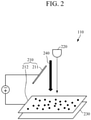
FIG. 2 , theimage obtaining device 110 includes a particulate matter adsorbingdevice 210, alight source 220, and animage generating device 230. - The particulate matter adsorbing
device 210 may charge the particulate matter particles, and may adsorb the charged particulate matter particles. The particulate matter adsorbingdevice 210 may include afirst electrode 211, to which either one of a positive polarity or a negative polarity is applied to charge the particulate matter particles, and asecond electrode 212, to which the other one of the positive polarity and the negative polarity is applied to adsorb the charged particulate matter particles. - Once power is applied to the
first electrode 211 and thesecond electrode 212, an electric field may be generated between thefirst electrode 211 and thesecond electrode 212. If the particulate matter particles flow in adirection 240 from thefirst electrode 211 to thesecond electrode 212, the particulate matter particles may be electrically charged while passing through thefirst electrode 211. In this case, when the polarity, applied to thefirst electrode 211, is a positive polarity, the particulate matter particles are positively (+) charged, and when the polarity, applied to thefirst electrode 211, is a negative polarity, the particulate matter particles are negatively (-) charged. The charged particulate matter particles may be adsorbed on thesecond electrode 212. A polarity, applied to thesecond electrode 212, is opposite to a polarity applied to thefirst electrode 211, such that thesecond electrode 212 may have electrical properties which are opposite to those of the charged particulate matter particles. Accordingly, the particulate matter particles, which are electrically charged while passing through thefirst electrode 211, may be adsorbed automatically on thesecond electrode 212. - In an example embodiment, the
first electrode 211 may have a bar shape as illustrated inFIG. 2 . However, thefirst electrode 211 is not limited thereto, and may have various shapes, such as a plate shape having holes such that air containing particulate matter particles may pass therethrough, a grid shape, and the like. Further, as illustrated inFIG. 2 , thesecond electrode 212 may have a plate shape, such that the charged particulate matter particles may be adsorbed thereon. - In an example embodiment, the
first electrode 211 and thesecond electrode 212 may be formed as a transparent electrode, to not obstruct the passage of light. For example, thefirst electrode 211 and thesecond electrode 212 may be made of indium tin oxide (ITO), indium zinc oxide (IZO), stannic oxide (SnO2), zinc oxide (ZnO), graphene, silver nanowire, conductive polymer (e.g., PEDOT:PSS), carbon nanotube, and the like. - While
FIG. 2 illustrates twoelectrodes - The
light source 220 may emit light to the particulate matter particles adsorbed on thesecond electrode 212. To this end, thelight source 220 may include one or more light sources. For example, each light source may emit light of a predetermined wavelength, for example, visible light, near-infrared light, mid-infrared light, and the like, to the particulate matter particles adsorbed on thesecond electrode 212. However, wavelengths of light emitted by each light source may vary depending on the measurement purpose or types of analytes. Further, each light source is not necessarily formed of a single light-emitting body, and may be formed of an array of a plurality of light-emitting bodies. If each light source is formed of a plurality of light-emitting bodies, the plurality of light-emitting bodies may emit light of the same wavelength or light of different wavelengths. In addition, some of the plurality of light-emitting bodies may emit light of the same wavelength, and others may emit light of different wavelengths. In an example embodiment, each light source may include a light emitting diode (LED), a laser diode, a phosphor, and the like, but this is merely an example, and the light source is not limited thereto. - In an example embodiment, the
light source 220 may further include a filter, for example, a clean-up filter, a bandpass filter, and the like, for selecting light of a specific wavelength, and/or an optical element, for example, reflecting mirror, and the like, for directing the emitted light toward a desired position. - The
image generating device 230 may generate an image of the particulate matter particles by receiving light, having passed through the particulate matter particles adsorbed on thesecond electrode 212, or light reflected or scattered from the particulate matter particles adsorbed on thesecond electrode 212. In an example embodiment, theimage generating device 230 may generate a hologram image of the particulate matter particles by receiving light having passed through, or reflected or scattered from, the particulate matter particles adsorbed on thesecond electrode 212, and may reconstruct the hologram image based on scattering characteristics of the particulate matter particles. In this case, theimage generating device 230 may improve the resolution of the image by using a machine learning algorithm such as deep learning, and the like. - The
image generating device 230 may be disposed below thesecond electrode 212. For example, theimage generating device 230 may be disposed adjacent to a bottom portion of thesecond electrode 212. Theimage generating device 230 may include at least one of a charge-coupled device (CCD) and a complementary metal oxide semiconductor (CMOS). - The
spectrum obtaining device 120 may obtain a Raman spectrum of the particulate matter particles contained in the introduced air. For example, thespectrum obtaining device 120 may emit light to the particulate matter particles contained in the introduced air, and may generate a Raman spectrum of the particulate matter particles by receiving Raman scattered light of the particulate matter particles. - As illustrated in
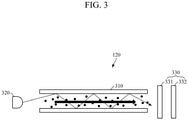
FIG. 3 , thespectrum obtaining device 120 may include awaveguide 310, alight source 230, and aspectrum generating device 330. - The particulate matter particles are introduced into the
waveguide 310, and thewaveguide 310 may transmit Raman scattered light of the particulate matter particles, which is produced by light emitted by thelight source 320, to thespectrum generating device 330. Thewaveguide 310 may be formed as a hollow conduit having a relatively high conductivity. - In addition, the particulate matter particles may flow from an inlet of the
waveguide 310 to an outlet thereof, and may be discharged to the outside from the outlet of thewaveguide 310. - Once the particulate matter particles are introduced into the
waveguide 310, thelight source 320 may emit light to the particulate matter particles introduced into thewaveguide 310. To this end, thelight source 320 may include one or more light sources. For example, each light source may emit light of a predetermined wavelength, for example, visible light, near-infrared light, mid-infrared light, and the like, to the particulate matter particles introduced into thewaveguide 310. However, wavelengths of light emitted by each light source may vary depending on the measurement purpose or types of analytes. Further, each light source is not necessarily formed of a single light-emitting body, and may be formed of an array of a plurality of light-emitting bodies. If each light source is formed of a plurality of light-emitting bodies, the plurality of light-emitting bodies may emit light of the same wavelength or light of different wavelengths. In addition, some of the plurality of light-emitting bodies may emit light of the same wavelength, and others may emit light of different wavelengths. In an example embodiment, each light source may include a light emitting diode (LED), a laser diode, a phosphor, and the like, but this is merely an example, and the light source is not limited thereto. - In an example embodiment, the
light source 320 may further include a filter, for example, a clean-up filter, a bandpass filter, and the like, for selecting light of a specific wavelength, and/or an optical element, for example, reflecting mirror, and the like, for directing the emitted light toward a desired position. - The
spectrum generating device 330 may generate a Raman spectrum of the particulate matter particles by receiving the Raman scattered light of the particulate matter particles introduced into thewaveguide 310. To this end, thespectrum generating device 330 may include a spectrometer 331 and a generating device 332. - The spectrometer 331 may receive the Raman scattered light of the particulate matter particles introduced into the
waveguide 310, and may separate the Raman scattered light into wavelengths. In an example embodiment, the spectrometer 331 may include at least one of a prism, a grating, a filter, and the like, but is not limited thereto. - The generating device 332 may generate a Raman spectrum by receiving the Raman scattered light which is separated into wavelengths. In an example embodiment, the generating device 332 may include at least one a charge-coupled device (CCD) and a complementary metal oxide semiconductor (CMOS), but is not limited thereto.
- The
processor 130 may control the overall operation of theapparatus 100 for measuring particulate matter. - Once air containing particulate matter particles is introduced, the
processor 130 may control theimage obtaining device 110 to obtain an image of the particulate matter particles, and may control thespectrum obtaining device 120 to obtain a Raman spectrum of the particulate matter particles. - The
processor 130 may obtain information on the particulate matter particles by analyzing the obtained image and the obtained Raman spectrum of the particulate matter particles. In this case, the information on the particulate matter particles may include the size, concentration, components, and the like of the particulate matter particles. - In an example embodiment, the
processor 130 may determine the size and concentration of the particulate matter particles by analyzing the image of the particulate matter particles. For example, by determining the size and number of the particulate matter particles in the image of the particulate matter particles, theprocessor 130 may determine the size and concentration of the particulate matter particles contained in the introduced air. - In an example embodiment, the
processor 130 may determine the components of the particulate matter particles by analyzing the Raman spectrum of the particulate matter particles. A frequency, at which a Raman spectrum peak appears, may vary depending on the components of the particles. Accordingly, by referring to information on the frequency, at which the Raman spectrum peak appears, for each component of the particles, theprocessor 130 may determine the components of the particulate matter particles. In this case, information on the frequency, at which the Raman spectrum peak appears, for each component of the particles may be derived experimentally, and may be stored in an internal or external memory of theprocessor 130. - In addition, before determining the components of the particulate matter particles by analyzing the Raman spectrum thereof, the
processor 130 may remove noise from the Raman spectrum. The Raman spectrum of the particulate matter particles includes much noise, and the noise included in the Raman spectrum may be divided into simple additive noise derived from an external environment, and background noise derived from autofluorescence. Theprocessor 130 may remove the simple additive noise from the Raman spectrum by using a low-pass filter, for example, moving average filter, and the like. Further, theprocessor 130 may estimate a baseline of the Raman spectrum, and may remove the background noise by subtracting the estimated baseline from the Raman spectrum. In this case, the baseline may be estimated using a first-order differential method, a rolling-ball method, and the like. Here, the first-order differential method uses characteristics of background noise exhibiting a gradual change over the entire range. In the first-order differential method, a baseline is estimated by differentiating a spectrum, finding a significant peak, cutting out the corresponding peak area, and performing interpolation. Further, in the rolling-ball method, a trace of a highest point of a hypothetical ball that rolls underneath a spectrum is considered as a baseline. -
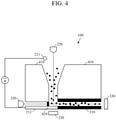
FIG. 4 is a diagram illustrating a structure of an apparatus for measuring particulate matter according to an example embodiment. The apparatus for measuring particulate matter ofFIG. 4 may be an example of the structure of theapparatus 100 for measuring particulate matter ofFIG. 1 . - Referring to
FIG. 4 , afirst electrode 211 is disposed near an inlet of astructure 410, into which air is introduced, and thesecond electrode 212 may be disposed below thestructure 410. When power is applied to thefirst electrode 211 and thesecond electrode 212 and an electric field is generated therebetween, the particulate matter particles, contained in the introduced air, may be electrically charged while passing through thefirst electrode 211. The charge particulate matter may flow downwards along the generated electric field and a passage of thestructure 410, to be adsorbed on thesecond electrode 212. - The
light source 220 may be disposed near the inlet of thestructure 410 to emit light to the particulate matter particles, which are adsorbed on thesecond electrode 212 disposed below thestructure 410, and theimage generating device 230 is dispose below thesecond electrode 212, and generates an image of the particulate matter particles by receiving light having passed through thesecond electrode 212. - The
waveguide 310 is disposed below thestructure 410 in a direction parallel to thesecond electrode 212. Once the image of the particulate matter particles is obtained, and the electric field generated between thefirst electrode 211 and thesecond electrode 212 is removed, the particulate matter particles adsorbed on thesecond electrode 212 are desorbed to be introduced into thewaveguide 310, and then may flow along thewaveguide 310 to be discharged to the outside. That is, thewaveguide 310 may function as a discharge port for the particulate matter particles. - The
light source 320 may be disposed near the inlet of thewaveguide 310 to emit light to the particulate matter particles introduced into thewaveguide 310, and thespectrum generating device 330 is disposed near an outlet of thewaveguide 310 to receive Raman scattered light of the particulate matter particles, and may generate a Raman spectrum of the particulate matter particles. - In addition, in order to prevent or reduce the particulate matter particles, desorbed from the
second electrode 212, from flowing in a direction other than thewaveguide 330, theapparatus 100 for measuring particulate matter may include a blockingpart 420 for blocking holes except for the inlet of thewaveguide 310. The blockingpart 420 may be made of a transparent material so as not to affect the passage of light, or may be formed as a filter for passing light of a predetermined wavelength. -
FIG. 5 is a block diagram illustrating an apparatus for measuring particulate matter according to another embodiment of the present disclosure. - Referring to
FIG. 5 , theapparatus 500 for measuring particulate matter according to another embodiment of the present disclosure includes theimage obtaining device 110, thespectrum obtaining device 120, theprocessor 130, aninput interface 510, astorage 520, acommunication interface 530, and anoutput interface 540. Here, theimage obtaining device 110, thespectrum obtaining device 120, and theprocessor 130 are described above with reference toFIGS. 1 to 4 , such that detailed description thereof will be omitted. - The
input interface 510 may receive input of various operation signals from a user. In an example embodiment, theinput interface 510 may include a keypad, a dome switch, a static pressure or capacitance touch pad, a jog wheel, a jog switch, a hardware (H/W) button, and the like. The touch pad, which forms a layer structure with a display, may be a touch screen. - The
storage 520 may store programs or commands for operation of theapparatus 500 for measuring particulate matter, and may store data input to and processed by theapparatus 500 for measuring particulate matter. Further, thestorage 520 may store image data obtained by theimage obtaining device 110, Raman spectrum data obtained by thespectrum obtaining device 120, information on particulate matter particles determined by theprocessor 130, data required for theprocessor 130 to determine the information on particulate matter particles, for example, information on a frequency, at which a Raman spectrum peak appears, for each component of the particles, and the like. - The
storage 520 may include at least one storage medium of a flash memory type memory, a hard disk type memory, a multimedia card micro type memory, a card type memory (e.g., an SD memory, an XD memory, etc.), a random access memory (RAM), a static random access memory (SRAM), a read only memory (ROM), an electrically erasable programmable read only memory (EEPROM), a programmable read only memory (PROM), a magnetic memory, a magnetic disk, and an optical disk, and the like. Further, theapparatus 500 for measuring particulate matter may operate an external storage medium, such as web storage and the like, which performs a storage function of thestorage 520 on the Internet. - The
communication interface 530 may communicate with an external device. For example, thecommunication interface 530 may transmit, to the external device, data input from a user through theinput interface 510, the image data obtained by theimage obtaining device 110, the Raman spectrum data obtained by thespectrum obtaining device 120, the information on particulate matter particles determined by theprocessor 130, the data required for theprocessor 130 to determine the information on particulate matter particles, for example, information on a frequency, at which a Raman spectrum peak appears, for each component of the particles, and the like; or may receive, from the external device, various data useful for determining the information on particulate matter particles. - In this case, the external device may be equipment using the image data obtained by the
image obtaining device 110, the Raman spectrum data obtained by thespectrum obtaining device 120, the information on particulate matter particles determined by theprocessor 130, the data required for theprocessor 130 to determine the information on particulate matter particles, for example, information on a frequency, at which a Raman spectrum peak appears, for each component of the particles, and the like, a printer to print out results, or a display to display the results. In addition, the external device may be a digital television (TV), a desktop computer, a cellular phone, a smartphone, a tablet personal computer (PC), a laptop computer, a personal digital assistant (PDA), a portable multimedia player (PMP), a navigation device, an MP3 player, a digital camera, a wearable device, and the like, but is not limited thereto. - The
communication interface 530 may communicate with an external device by using Bluetooth communication, Bluetooth Low Energy (BLE) communication, near field communication (NFC), WLAN communication, Zigbee communication, infrared data association (IrDA) communication, Wi-Fi Direct (WFD) communication, ultra-wideband (UWB) communication, Ant+ communication, WIFI communication, radio frequency identification (RFID) communication, 3G communication, 4G communication, 5G communication, and the like. However, embodiments are not limited thereto. - The
output interface 540 may output the image data obtained by theimage obtaining device 110, the Raman spectrum data obtained by thespectrum obtaining device 120, the information on particulate matter particles determined by theprocessor 130, the data required for theprocessor 130 to determine the information on particulate matter particles, for example, information on a frequency, at which a Raman spectrum peak appears, for each component of the particles, and the like. In an example embodiment, theoutput interface 540 may output the image data obtained by theimage obtaining device 110, the Raman spectrum data obtained by thespectrum obtaining device 120, the information on particulate matter particles determined by theprocessor 130, the data required for theprocessor 130 to determine the information on particulate matter particles, for example, information on a frequency, at which a Raman spectrum peak appears, for each component of the particles, and the like by using at least one of an acoustic method, a visual method, and a tactile method. To this end, theoutput interface 540 may include a display, a speaker, a vibrator, and the like. -
FIG. 6 is a flowchart illustrating a method of measuring particulate matter according to an example embodiment. The method of measuring particulate matter ofFIG. 6 may be performed by theapparatus FIG. 1 orFIG. 5 . - Referring to
FIG. 6 , the apparatus for measuring particulate matter may obtain an image of particulate matter particles, contained in the introduced air, using lens-free imaging (610). For example, the apparatus for measuring particulate matter may charge the particulate matter particles contained in the introduced air, and may adsorb the charged particulate matter particles. Further, the apparatus for measuring particulate matter may emit light to the adsorbed particulate matter particles, and may generate an image of the particulate matter particles by receiving light having passed through, or reflected or scattered from, the particulate matter particles. - By applying power to the first electrode and the second electrode, the apparatus for measuring particulate matter may generate an electric field between the first electrode and the second electrode. The particulate matter particles may be electrically charged while passing through the first electrode, and the charged particulate matter particles may be adsorbed on the second electrode. The apparatus for measuring particulate matter may emit light to the particulate matter particles adsorbed on the second electrode, and may generate an image of the particulate matter particles by receiving light having passed through the particulate matter particles or light reflected or scattered from the particulate matter particles. For example, the apparatus for measuring particulate matter may generate a hologram image of the particulate matter particles by receiving light having passed through, or reflected or scattered from, the particulate matter particles, and may reconstruct the hologram image based on scattering characteristics of the particulate matter particles.
- The apparatus for measuring particulate matter may obtain a Raman spectrum of the particulate matter particles contained in the introduced air (620). For example, when the particulate matter particles are desorbed from the second electrode to be introduced into the waveguide, the apparatus for measuring particulate matter may emit light to the particulate matter particles, and may generate a Raman spectrum of the particulate matter particles by receiving Raman scattered light of the particulate matter particles. In this case, the waveguide may function as a discharge port for the particulate matter particles.
- The apparatus for measuring particulate matter may obtain information on the particulate matter particles by analyzing the obtained image and Raman spectrum of the particulate matter particles (630). In this case, the information on the particulate matter particles may include the size, concentration, components, and the like of the particulate matter particles.
- In an example embodiment, the apparatus for measuring particulate matter may determine the size and concentration of the particulate matter particles by analyzing the image of the particulate matter particles. For example, by determining the size and number of the particulate matter particles in the image of the particulate matter particles, the apparatus for measuring particulate matter may determine the size and concentration of the particulate matter particles contained in the introduced air.
- In an example embodiment, the apparatus for measuring particulate matter may determine the components of the particulate matter particles by analyzing the Raman spectrum of the particulate matter particles. A frequency, at which a Raman spectrum peak appears, may vary depending on the components of the particles. Accordingly, by referring to information on the frequency, at which the Raman spectrum peak appears, for each component of the particles, the apparatus for measuring particulate matter may determine the components of the particulate matter particles. In this case, information on the frequency, at which the Raman spectrum peak appears, for each component of the particles may be derived experimentally, and may be stored in an internal or external memory.
- The present disclosure can be realized as a computer-readable code written on a computer-readable recording medium. Codes and code segments needed for realizing the present disclosure can be easily deduced by computer programmers of ordinary skill in the art. The computer-readable recording medium may be any type of recording device in which data is stored in a computer-readable manner. Examples of the computer-readable recording medium include a ROM, a RAM, a CD-ROM, a magnetic tape, a floppy disc, an optical disk, and the like. Further, the computer-readable recording medium can be distributed over a plurality of computer systems connected to a network so that a computer-readable recording medium is written thereto and executed therefrom in a decentralized manner.
- While example embodiments have been described with reference to the figures, it will be understood by those of ordinary skill in the art that various changes in form and details may be made therein without departing from the scope of the present disclosure as defined by the following claims.
Claims (9)
- An apparatus (100) for measuring particulate matter, the apparatus comprising:an image obtaining device (110) configured to charge particulate matter particles included in air that is introduced to the image obtaining device, and to obtain an image of the charged particulate matter particles, preferably based on lens-free imaging;wherein the image obtaining device (110) comprises:a particulate matter adsorbing device (210) configured to charge the particulate matter particles and to adsorb the charged particulate matter particles;a light source (220) configured to emit light to the adsorbed particulate matter particles; andan image generating device (230) configured to generate an image of the particulate matter particles by receiving light having passed through the adsorbed particulate matter particles, light reflected from the adsorbed particulate matter particles, or light scattered from the adsorbed particulate matter particles;wherein the particulate matter adsorbing device (210) comprises:a first electrode (211) to which one of a positive polarity or a negative polarity is applied and configured to charge the particulate matter particles; anda second electrode (212) to which the other one of the positive polarity and the negative polarity is applied and configured to adsorb the charged particulate matter particles; andwherein the apparatus (100) further comprises:a processor (130) configured to determine a size of the particulate matter particles and a concentration of the particulate matter particles based on the obtained image;characterized bya spectrum obtaining device (120) configured to obtain a Raman spectrum of the charged particulate matter particles; andthe processor (130) being further configured to determine components of the particulate matter particles based on the obtained Raman spectrum;wherein the spectrum obtaining device (120) comprises:a waveguide (310) into which the charged particulate matter particles are introduced; anda spectrum generating device (330) configured to generate the Raman spectrum of the charged particulate matter particles by receiving Raman scattered light of the charged particulate matter particles introduced into the waveguide; andwherein the second electrode (212) is configured to desorb the particulate matter particles, once the image of the particulate matter particles is obtained, to be introduced into the waveguide (310).
- The apparatus of claim 1, wherein the second electrode has a plate shape.
- The apparatus of claim 1 or 2, wherein the second electrode is formed of one of indium tin oxide (ITO), indium zinc oxide (IZO), stannic oxide (SnO2), zinc oxide (ZnO), graphene, silver nanowire, conductive polymer (e.g., PEDOT:PSS), and carbon nanotube.
- The apparatus of any one of claims 1 to 3, wherein the image generating device comprises at least one of a charge-coupled device (CCD) and a complementary metal oxide semiconductor (CMOS).
- The apparatus of any one of claims 1 to 4, comprising:
a light source (230) configured to emit light to the charged particulate matter particles introduced into the waveguide. - The apparatus of any one of claim1 1 to 5, wherein the waveguide is configured to discharge the charged particulate matter particles to an outside of the apparatus for measuring particulate matter.
- The apparatus of claim 5 or 6, wherein:the light source is disposed proximate to an inlet of the waveguide; andthe spectrum generating device is disposed proximate to an outlet of the waveguide.
- The apparatus of any one of claims 1 to 7, wherein the spectrum generating device comprises:a spectrometer (331) configured to separate the Raman scattered light into light of different wavelengths, in particular, wherein the spectrometer comprises at least one of a prism, a grating, and a filter; anda generating device (332) configured to obtain the Raman spectrum by receiving the Raman scattered light which is separated into the light of different wavelengths, in particular, wherein the generating device comprises at least one of a charge-coupled device (CCD) and a complementary metal oxide semiconductor (CMOS).
- A method of measuring particulate matter, the method comprising:charging particulate matter particles included in air;obtaining an image of the charged particulate matter particles, preferably based on lens-free imaging; anddetermining a size of the particulate matter particles and a concentration of the particulate matter particles based on the obtained image;wherein the obtaining of the image comprises:adsorbing the charged particulate matter particles;emitting light to the adsorbed particulate matter particles; andgenerating an image of the particulate matter particles by receiving light having passed through the adsorbed particulate matter particles, light reflected from the adsorbed particulate matter particles, or light scattered from the adsorbed particulate matter particles;characterized byobtaining a Raman spectrum of the charged particulate matter particles; anddetermining components of the particulate matter particles based on the obtained Raman spectrum;
wherein the obtaining of the Raman spectrum comprises:desorbing the particulate matter particles, once the image of the particulate matter particles is obtained, and introducing the particulate matter particles into the waveguide;emitting light to the charged particulate matter particles introduced into the waveguide; andgenerating a Raman spectrum of the charged particulate matter particles by receiving Raman scattered light of the charged particulate matter particles introduced into the waveguide.
Applications Claiming Priority (1)
| Application Number | Priority Date | Filing Date | Title |
|---|---|---|---|
| KR1020190094822A KR102739071B1 (en) | 2019-08-05 | 2019-08-05 | Particulate matter measurement apparatus and method |
Publications (2)
| Publication Number | Publication Date |
|---|---|
| EP3772643A1 EP3772643A1 (en) | 2021-02-10 |
| EP3772643B1 true EP3772643B1 (en) | 2022-03-09 |
Family
ID=70738346
Family Applications (1)
| Application Number | Title | Priority Date | Filing Date |
|---|---|---|---|
| EP20174912.4A Active EP3772643B1 (en) | 2019-08-05 | 2020-05-15 | Apparatus and method for measuring particulate matter |
Country Status (4)
| Country | Link |
|---|---|
| US (1) | US11112363B2 (en) |
| EP (1) | EP3772643B1 (en) |
| KR (1) | KR102739071B1 (en) |
| CN (1) | CN112326515B (en) |
Families Citing this family (3)
| Publication number | Priority date | Publication date | Assignee | Title |
|---|---|---|---|---|
| KR102735781B1 (en) * | 2022-07-20 | 2024-11-28 | 주식회사 사이버네틱스이미징시스템즈 | Pathological sample image scanning and raman signal simultaneous acquisition system and method therefor |
| KR102744510B1 (en) * | 2022-11-15 | 2024-12-18 | 허목 | Energy-saving IoT fine dust measuring device |
| KR102858909B1 (en) | 2025-03-13 | 2025-09-12 | 서울특별시 | Method for analyzing microplastics contained in fine dust |
Family Cites Families (38)
| Publication number | Priority date | Publication date | Assignee | Title |
|---|---|---|---|---|
| US4786472A (en) | 1986-08-21 | 1988-11-22 | R. J. Reynolds Tobacco Company | Air sampling device |
| DE4339834A1 (en) | 1993-11-23 | 1995-05-24 | Rheinische Werkzeug & Maschf | Method and device for grain size analysis in the fine and fine grain range |
| US5510611A (en) | 1994-02-25 | 1996-04-23 | Yokogawa Electric Corporation | Particle component analyzing apparatus, and equivalent particle diameter measuring method using same |
| JP2001066266A (en) * | 1999-08-27 | 2001-03-16 | Shimadzu Corp | Suspended particulate matter measurement device |
| EP1273901A1 (en) * | 2001-07-02 | 2003-01-08 | Université de Liège | Method and apparatus for automatic measurement of particle size and form |
| JP4085941B2 (en) | 2003-09-17 | 2008-05-14 | 株式会社日立製作所 | Analysis equipment |
| KR100532287B1 (en) * | 2003-09-17 | 2005-11-29 | 삼성전자주식회사 | Partcle removing apparatus for camera module and method thereof |
| KR20060105755A (en) * | 2003-11-21 | 2006-10-11 | 코닌클리케 필립스 일렉트로닉스 엔.브이. | Method and apparatus for reducing edge image retention in electrophoretic display devices |
| KR100567788B1 (en) * | 2004-02-13 | 2006-04-05 | 주식회사 현대교정인증기술원 | Particle Measuring Machine and Particle Measuring Method |
| DE102004012105A1 (en) | 2004-03-12 | 2005-09-22 | Führer, Gerhard, Dr. | Sampling method and analysis kit for conducting indoor pollution analysis |
| CN101326276A (en) * | 2005-12-12 | 2008-12-17 | 美利肯公司 | cleaning device |
| CN100555031C (en) * | 2006-05-23 | 2009-10-28 | 宸鸿光电科技股份有限公司 | Processing method for making transparent electrode on transparent substrate invisible |
| JP4859626B2 (en) | 2006-10-31 | 2012-01-25 | 三菱重工業株式会社 | Fine particle component analyzer |
| CN101715550B (en) | 2007-05-12 | 2012-03-14 | 罗杰·L.·昂格尔 | Compact, low cost particle sensor |
| WO2009037701A2 (en) * | 2007-09-20 | 2009-03-26 | Novatrans Group Sa | Color image sensor device using a photocathode and method of its use |
| JP2009145414A (en) * | 2007-12-11 | 2009-07-02 | Bridgestone Corp | Method of manufacturing information display panel and filling apparatus for particulate display medium used for the same |
| WO2012016159A2 (en) | 2010-07-30 | 2012-02-02 | Buglab Llc | Optical sensor for rapid determination of particulate concentration |
| JP5509163B2 (en) * | 2011-08-11 | 2014-06-04 | 京セラドキュメントソリューションズ株式会社 | Positively chargeable toner |
| JP6284294B2 (en) * | 2012-05-31 | 2018-02-28 | イー インク コーポレイション | Image display medium drive device, image display device, and drive program |
| WO2014024556A1 (en) | 2012-08-07 | 2014-02-13 | ソニー株式会社 | Laminar flow monitoring method for microparticle measurement device, microparticle analysis method, and microparticle measurement device |
| CN103855601A (en) * | 2012-12-03 | 2014-06-11 | 中国科学院大连化学物理研究所 | Method for reducing hydrogen stimulated Raman scattering threshold value |
| EP2824445B1 (en) * | 2013-07-08 | 2016-03-02 | Fei Company | Charged-particle microscopy combined with raman spectroscopy |
| CN103940799B (en) * | 2014-03-10 | 2016-08-24 | 北京理工大学 | Confocal Brillouin-the method for measuring Raman spectrum of laser twin shaft and device |
| KR101551289B1 (en) | 2014-05-22 | 2015-09-09 | 한국과학기술연구원 | Fine particulate matters measuring device and fine particulate matters measuring method using the same |
| KR102002665B1 (en) | 2015-01-23 | 2019-10-01 | 전자부품연구원 | System for measuring fine particulate and gas particulate |
| KR101678175B1 (en) | 2015-02-25 | 2016-11-21 | (주)켄텍 | Apparatus for automatically measuring particulate matter and simultaneously sampling of heavy metal |
| WO2016174523A1 (en) * | 2015-04-27 | 2016-11-03 | Illumina France Sarl | Systems and methods of identifying and/or tracking particles in a droplet, wherein the particle can be a cell |
| WO2017051327A1 (en) | 2015-09-22 | 2017-03-30 | Imageprovision Technology Pvt. Ltd. | Method and system for detection and classification of particles based on processing of microphotographic images |
| US9921144B2 (en) | 2016-06-29 | 2018-03-20 | Honeywell International Inc. | Particulate matter detector |
| CN106139145B (en) * | 2016-07-14 | 2020-03-10 | 国家纳米科学中心 | Exciton-plasmon coupling system, construction method thereof and method for enhancing photosensitizer singlet oxygen generation by coupling system |
| CN106404616B (en) | 2016-08-31 | 2018-12-25 | 孙扬 | A kind of method of airborne fine particulate matter (PM2.5) discharge source resolution positioning |
| KR101721607B1 (en) | 2016-11-10 | 2017-04-03 | 대한민국 | Apparatus for rotating-type analyzing particles in particulate matter and analyzing method using the same |
| EP3555599B1 (en) | 2016-12-19 | 2024-07-31 | Massachusetts Institute of Technology | Systems and methods for monitoring air particulate matter |
| CN108153186A (en) | 2017-12-12 | 2018-06-12 | 大连理创科技有限公司 | An air quality monitoring system |
| CN107942597A (en) * | 2018-01-02 | 2018-04-20 | 京东方科技集团股份有限公司 | Electronic Paper and its display methods, display device |
| KR101914971B1 (en) | 2018-03-23 | 2018-11-06 | 주식회사 대은계전 | Environmental monitoring and instrumentation and control unit |
| CN109211847B (en) * | 2018-09-29 | 2020-06-30 | 西北大学 | A method for analyzing the chemical composition of a single suspended particle using an analytical device |
| CN109239053B (en) * | 2018-10-29 | 2020-08-07 | 中国科学院上海技术物理研究所 | An Astronaut Urine Detection System Based on Liquid Core Waveguide Raman Spectroscopy |
-
2019
- 2019-08-05 KR KR1020190094822A patent/KR102739071B1/en active Active
-
2020
- 2020-03-16 US US16/819,618 patent/US11112363B2/en active Active
- 2020-03-30 CN CN202010240300.2A patent/CN112326515B/en active Active
- 2020-05-15 EP EP20174912.4A patent/EP3772643B1/en active Active
Also Published As
| Publication number | Publication date |
|---|---|
| KR20210016716A (en) | 2021-02-17 |
| US11112363B2 (en) | 2021-09-07 |
| KR102739071B1 (en) | 2024-12-06 |
| EP3772643A1 (en) | 2021-02-10 |
| CN112326515A (en) | 2021-02-05 |
| CN112326515B (en) | 2024-05-31 |
| US20210041365A1 (en) | 2021-02-11 |
Similar Documents
| Publication | Publication Date | Title |
|---|---|---|
| EP3772643B1 (en) | Apparatus and method for measuring particulate matter | |
| Xue et al. | Advances in miniaturized computational spectrometers | |
| Al Mamun et al. | Sensors and systems for wearable environmental monitoring toward IoT-enabled applications: A review | |
| Zhou et al. | Personal information from latent fingerprints using desorption electrospray ionization mass spectrometry and machine learning | |
| US20140228655A1 (en) | Touch-sensitive device and method | |
| Jin et al. | Nanosensor-based flexible electronic assisted with light fidelity communicating technology for volatolomics-based telemedicine | |
| US20160198129A1 (en) | Room monitoring device | |
| JP2015516714A (en) | Measuring the quality of experience associated with mobile devices | |
| Zhu et al. | Ultrasensitive online NO sensor based on a distributed parallel self-regulating neural network and ultraviolet differential optical absorption spectroscopy for exhaled breath diagnosis | |
| EP3770579B1 (en) | Apparatus and method for measuring particulate matter | |
| Komatsu et al. | THz gas sensing using terahertz time-domain spectroscopy with ceramic architecture | |
| Matthies et al. | Prototyping smart eyewear with capacitive sensing for facial and head gesture detection | |
| Zhu et al. | Detection of breath nitric oxide at ppb level based on multiperiodic spectral reconstruction neural network | |
| Güngör et al. | Investigating well potential parameters on neural spike enhancement in a stochastic-resonance pre-emphasis algorithm | |
| Lee et al. | Development of a forest fire detection system using a drone-based convolutional neural network model | |
| Wang et al. | Gas graph convolutional transformer for robust generalization in adaptive gas mixture concentration estimation | |
| Zhou et al. | TCS-Fall: Cross-individual fall detection system based on channel state information and time-continuous stack method | |
| Belal et al. | Advances In Nanogenerators Enabled Smart Mask-based Self-Powered Health Monitoring Units | |
| Bogue | Emerging applications driving innovations in gas sensing | |
| Almania et al. | Dynamic Hover Gesture Classification using Photovoltaic Sensor and Machine Learning | |
| Bansal et al. | EEG based detection of area of interest in a web page | |
| Wu et al. | Towards Real-world Application: Multi-view Sensor Unifying Framework For Biological Particle Viability Assessment | |
| Nguyen et al. | Enhanced discrimination of acetone and ethanol gases via nano-structured MOS sensors and machine learning approaches | |
| Kumar et al. | Analysis of EEG fluctuation patterns using nonlinear phase-based functional connectivity measures for emotion recognition | |
| NASRI | CHEMICAL SURFACE MODIFICATION, TEMPERATURE MODULATION, AND |
Legal Events
| Date | Code | Title | Description |
|---|---|---|---|
| PUAI | Public reference made under article 153(3) epc to a published international application that has entered the european phase |
Free format text: ORIGINAL CODE: 0009012 |
|
| STAA | Information on the status of an ep patent application or granted ep patent |
Free format text: STATUS: THE APPLICATION HAS BEEN PUBLISHED |
|
| AK | Designated contracting states |
Kind code of ref document: A1 Designated state(s): AL AT BE BG CH CY CZ DE DK EE ES FI FR GB GR HR HU IE IS IT LI LT LU LV MC MK MT NL NO PL PT RO RS SE SI SK SM TR |
|
| AX | Request for extension of the european patent |
Extension state: BA ME |
|
| STAA | Information on the status of an ep patent application or granted ep patent |
Free format text: STATUS: REQUEST FOR EXAMINATION WAS MADE |
|
| 17P | Request for examination filed |
Effective date: 20210803 |
|
| RBV | Designated contracting states (corrected) |
Designated state(s): AL AT BE BG CH CY CZ DE DK EE ES FI FR GB GR HR HU IE IS IT LI LT LU LV MC MK MT NL NO PL PT RO RS SE SI SK SM TR |
|
| GRAP | Despatch of communication of intention to grant a patent |
Free format text: ORIGINAL CODE: EPIDOSNIGR1 |
|
| STAA | Information on the status of an ep patent application or granted ep patent |
Free format text: STATUS: GRANT OF PATENT IS INTENDED |
|
| INTG | Intention to grant announced |
Effective date: 20211125 |
|
| GRAS | Grant fee paid |
Free format text: ORIGINAL CODE: EPIDOSNIGR3 |
|
| GRAA | (expected) grant |
Free format text: ORIGINAL CODE: 0009210 |
|
| STAA | Information on the status of an ep patent application or granted ep patent |
Free format text: STATUS: THE PATENT HAS BEEN GRANTED |
|
| AK | Designated contracting states |
Kind code of ref document: B1 Designated state(s): AL AT BE BG CH CY CZ DE DK EE ES FI FR GB GR HR HU IE IS IT LI LT LU LV MC MK MT NL NO PL PT RO RS SE SI SK SM TR |
|
| REG | Reference to a national code |
Ref country code: CH Ref legal event code: EP Ref country code: AT Ref legal event code: REF Ref document number: 1474557 Country of ref document: AT Kind code of ref document: T Effective date: 20220315 |
|
| REG | Reference to a national code |
Ref country code: IE Ref legal event code: FG4D |
|
| REG | Reference to a national code |
Ref country code: DE Ref legal event code: R096 Ref document number: 602020002116 Country of ref document: DE |
|
| REG | Reference to a national code |
Ref country code: LT Ref legal event code: MG9D |
|
| REG | Reference to a national code |
Ref country code: NL Ref legal event code: MP Effective date: 20220309 |
|
| PG25 | Lapsed in a contracting state [announced via postgrant information from national office to epo] |
Ref country code: SE Free format text: LAPSE BECAUSE OF FAILURE TO SUBMIT A TRANSLATION OF THE DESCRIPTION OR TO PAY THE FEE WITHIN THE PRESCRIBED TIME-LIMIT Effective date: 20220309 Ref country code: RS Free format text: LAPSE BECAUSE OF FAILURE TO SUBMIT A TRANSLATION OF THE DESCRIPTION OR TO PAY THE FEE WITHIN THE PRESCRIBED TIME-LIMIT Effective date: 20220309 Ref country code: NO Free format text: LAPSE BECAUSE OF FAILURE TO SUBMIT A TRANSLATION OF THE DESCRIPTION OR TO PAY THE FEE WITHIN THE PRESCRIBED TIME-LIMIT Effective date: 20220609 Ref country code: LT Free format text: LAPSE BECAUSE OF FAILURE TO SUBMIT A TRANSLATION OF THE DESCRIPTION OR TO PAY THE FEE WITHIN THE PRESCRIBED TIME-LIMIT Effective date: 20220309 Ref country code: HR Free format text: LAPSE BECAUSE OF FAILURE TO SUBMIT A TRANSLATION OF THE DESCRIPTION OR TO PAY THE FEE WITHIN THE PRESCRIBED TIME-LIMIT Effective date: 20220309 Ref country code: BG Free format text: LAPSE BECAUSE OF FAILURE TO SUBMIT A TRANSLATION OF THE DESCRIPTION OR TO PAY THE FEE WITHIN THE PRESCRIBED TIME-LIMIT Effective date: 20220609 |
|
| REG | Reference to a national code |
Ref country code: AT Ref legal event code: MK05 Ref document number: 1474557 Country of ref document: AT Kind code of ref document: T Effective date: 20220309 |
|
| PG25 | Lapsed in a contracting state [announced via postgrant information from national office to epo] |
Ref country code: LV Free format text: LAPSE BECAUSE OF FAILURE TO SUBMIT A TRANSLATION OF THE DESCRIPTION OR TO PAY THE FEE WITHIN THE PRESCRIBED TIME-LIMIT Effective date: 20220309 Ref country code: GR Free format text: LAPSE BECAUSE OF FAILURE TO SUBMIT A TRANSLATION OF THE DESCRIPTION OR TO PAY THE FEE WITHIN THE PRESCRIBED TIME-LIMIT Effective date: 20220610 Ref country code: FI Free format text: LAPSE BECAUSE OF FAILURE TO SUBMIT A TRANSLATION OF THE DESCRIPTION OR TO PAY THE FEE WITHIN THE PRESCRIBED TIME-LIMIT Effective date: 20220309 |
|
| PG25 | Lapsed in a contracting state [announced via postgrant information from national office to epo] |
Ref country code: NL Free format text: LAPSE BECAUSE OF FAILURE TO SUBMIT A TRANSLATION OF THE DESCRIPTION OR TO PAY THE FEE WITHIN THE PRESCRIBED TIME-LIMIT Effective date: 20220309 |
|
| PG25 | Lapsed in a contracting state [announced via postgrant information from national office to epo] |
Ref country code: SM Free format text: LAPSE BECAUSE OF FAILURE TO SUBMIT A TRANSLATION OF THE DESCRIPTION OR TO PAY THE FEE WITHIN THE PRESCRIBED TIME-LIMIT Effective date: 20220309 Ref country code: SK Free format text: LAPSE BECAUSE OF FAILURE TO SUBMIT A TRANSLATION OF THE DESCRIPTION OR TO PAY THE FEE WITHIN THE PRESCRIBED TIME-LIMIT Effective date: 20220309 Ref country code: RO Free format text: LAPSE BECAUSE OF FAILURE TO SUBMIT A TRANSLATION OF THE DESCRIPTION OR TO PAY THE FEE WITHIN THE PRESCRIBED TIME-LIMIT Effective date: 20220309 Ref country code: PT Free format text: LAPSE BECAUSE OF FAILURE TO SUBMIT A TRANSLATION OF THE DESCRIPTION OR TO PAY THE FEE WITHIN THE PRESCRIBED TIME-LIMIT Effective date: 20220711 Ref country code: ES Free format text: LAPSE BECAUSE OF FAILURE TO SUBMIT A TRANSLATION OF THE DESCRIPTION OR TO PAY THE FEE WITHIN THE PRESCRIBED TIME-LIMIT Effective date: 20220309 Ref country code: EE Free format text: LAPSE BECAUSE OF FAILURE TO SUBMIT A TRANSLATION OF THE DESCRIPTION OR TO PAY THE FEE WITHIN THE PRESCRIBED TIME-LIMIT Effective date: 20220309 Ref country code: CZ Free format text: LAPSE BECAUSE OF FAILURE TO SUBMIT A TRANSLATION OF THE DESCRIPTION OR TO PAY THE FEE WITHIN THE PRESCRIBED TIME-LIMIT Effective date: 20220309 Ref country code: AT Free format text: LAPSE BECAUSE OF FAILURE TO SUBMIT A TRANSLATION OF THE DESCRIPTION OR TO PAY THE FEE WITHIN THE PRESCRIBED TIME-LIMIT Effective date: 20220309 |
|
| PG25 | Lapsed in a contracting state [announced via postgrant information from national office to epo] |
Ref country code: PL Free format text: LAPSE BECAUSE OF FAILURE TO SUBMIT A TRANSLATION OF THE DESCRIPTION OR TO PAY THE FEE WITHIN THE PRESCRIBED TIME-LIMIT Effective date: 20220309 Ref country code: IS Free format text: LAPSE BECAUSE OF FAILURE TO SUBMIT A TRANSLATION OF THE DESCRIPTION OR TO PAY THE FEE WITHIN THE PRESCRIBED TIME-LIMIT Effective date: 20220709 Ref country code: AL Free format text: LAPSE BECAUSE OF FAILURE TO SUBMIT A TRANSLATION OF THE DESCRIPTION OR TO PAY THE FEE WITHIN THE PRESCRIBED TIME-LIMIT Effective date: 20220309 |
|
| REG | Reference to a national code |
Ref country code: DE Ref legal event code: R097 Ref document number: 602020002116 Country of ref document: DE |
|
| PLBE | No opposition filed within time limit |
Free format text: ORIGINAL CODE: 0009261 |
|
| STAA | Information on the status of an ep patent application or granted ep patent |
Free format text: STATUS: NO OPPOSITION FILED WITHIN TIME LIMIT |
|
| REG | Reference to a national code |
Ref country code: BE Ref legal event code: MM Effective date: 20220531 |
|
| PG25 | Lapsed in a contracting state [announced via postgrant information from national office to epo] |
Ref country code: MC Free format text: LAPSE BECAUSE OF FAILURE TO SUBMIT A TRANSLATION OF THE DESCRIPTION OR TO PAY THE FEE WITHIN THE PRESCRIBED TIME-LIMIT Effective date: 20220309 Ref country code: LU Free format text: LAPSE BECAUSE OF NON-PAYMENT OF DUE FEES Effective date: 20220515 Ref country code: DK Free format text: LAPSE BECAUSE OF FAILURE TO SUBMIT A TRANSLATION OF THE DESCRIPTION OR TO PAY THE FEE WITHIN THE PRESCRIBED TIME-LIMIT Effective date: 20220309 |
|
| 26N | No opposition filed |
Effective date: 20221212 |
|
| PG25 | Lapsed in a contracting state [announced via postgrant information from national office to epo] |
Ref country code: SI Free format text: LAPSE BECAUSE OF FAILURE TO SUBMIT A TRANSLATION OF THE DESCRIPTION OR TO PAY THE FEE WITHIN THE PRESCRIBED TIME-LIMIT Effective date: 20220309 |
|
| PG25 | Lapsed in a contracting state [announced via postgrant information from national office to epo] |
Ref country code: IE Free format text: LAPSE BECAUSE OF NON-PAYMENT OF DUE FEES Effective date: 20220515 |
|
| PG25 | Lapsed in a contracting state [announced via postgrant information from national office to epo] |
Ref country code: BE Free format text: LAPSE BECAUSE OF NON-PAYMENT OF DUE FEES Effective date: 20220531 |
|
| P01 | Opt-out of the competence of the unified patent court (upc) registered |
Effective date: 20230520 |
|
| PG25 | Lapsed in a contracting state [announced via postgrant information from national office to epo] |
Ref country code: IT Free format text: LAPSE BECAUSE OF FAILURE TO SUBMIT A TRANSLATION OF THE DESCRIPTION OR TO PAY THE FEE WITHIN THE PRESCRIBED TIME-LIMIT Effective date: 20220309 |
|
| REG | Reference to a national code |
Ref country code: CH Ref legal event code: PL |
|
| PG25 | Lapsed in a contracting state [announced via postgrant information from national office to epo] |
Ref country code: LI Free format text: LAPSE BECAUSE OF NON-PAYMENT OF DUE FEES Effective date: 20230531 Ref country code: CH Free format text: LAPSE BECAUSE OF NON-PAYMENT OF DUE FEES Effective date: 20230531 |
|
| PG25 | Lapsed in a contracting state [announced via postgrant information from national office to epo] |
Ref country code: MK Free format text: LAPSE BECAUSE OF FAILURE TO SUBMIT A TRANSLATION OF THE DESCRIPTION OR TO PAY THE FEE WITHIN THE PRESCRIBED TIME-LIMIT Effective date: 20220309 Ref country code: CY Free format text: LAPSE BECAUSE OF FAILURE TO SUBMIT A TRANSLATION OF THE DESCRIPTION OR TO PAY THE FEE WITHIN THE PRESCRIBED TIME-LIMIT Effective date: 20220309 |
|
| PG25 | Lapsed in a contracting state [announced via postgrant information from national office to epo] |
Ref country code: HU Free format text: LAPSE BECAUSE OF FAILURE TO SUBMIT A TRANSLATION OF THE DESCRIPTION OR TO PAY THE FEE WITHIN THE PRESCRIBED TIME-LIMIT; INVALID AB INITIO Effective date: 20200515 |
|
| PG25 | Lapsed in a contracting state [announced via postgrant information from national office to epo] |
Ref country code: TR Free format text: LAPSE BECAUSE OF FAILURE TO SUBMIT A TRANSLATION OF THE DESCRIPTION OR TO PAY THE FEE WITHIN THE PRESCRIBED TIME-LIMIT Effective date: 20220309 |
|
| PG25 | Lapsed in a contracting state [announced via postgrant information from national office to epo] |
Ref country code: MT Free format text: LAPSE BECAUSE OF FAILURE TO SUBMIT A TRANSLATION OF THE DESCRIPTION OR TO PAY THE FEE WITHIN THE PRESCRIBED TIME-LIMIT Effective date: 20220309 |
|
| PGFP | Annual fee paid to national office [announced via postgrant information from national office to epo] |
Ref country code: DE Payment date: 20250408 Year of fee payment: 6 |
|
| PGFP | Annual fee paid to national office [announced via postgrant information from national office to epo] |
Ref country code: GB Payment date: 20250410 Year of fee payment: 6 |
|
| PGFP | Annual fee paid to national office [announced via postgrant information from national office to epo] |
Ref country code: FR Payment date: 20250409 Year of fee payment: 6 |