EP3772642B1 - Caractérisation d'aérosols - Google Patents
Caractérisation d'aérosols Download PDFInfo
- Publication number
- EP3772642B1 EP3772642B1 EP19213484.9A EP19213484A EP3772642B1 EP 3772642 B1 EP3772642 B1 EP 3772642B1 EP 19213484 A EP19213484 A EP 19213484A EP 3772642 B1 EP3772642 B1 EP 3772642B1
- Authority
- EP
- European Patent Office
- Prior art keywords
- electromagnetic radiation
- aerosol
- sensor
- intensity
- source
- Prior art date
- Legal status (The legal status is an assumption and is not a legal conclusion. Google has not performed a legal analysis and makes no representation as to the accuracy of the status listed.)
- Active
Links
Images


Classifications
-
- G—PHYSICS
- G01—MEASURING; TESTING
- G01N—INVESTIGATING OR ANALYSING MATERIALS BY DETERMINING THEIR CHEMICAL OR PHYSICAL PROPERTIES
- G01N15/00—Investigating characteristics of particles; Investigating permeability, pore-volume or surface-area of porous materials
- G01N15/02—Investigating particle size or size distribution
- G01N15/0205—Investigating particle size or size distribution by optical means
- G01N15/0211—Investigating a scatter or diffraction pattern
-
- G—PHYSICS
- G08—SIGNALLING
- G08B—SIGNALLING SYSTEMS, e.g. PERSONAL CALLING SYSTEMS; ORDER TELEGRAPHS; ALARM SYSTEMS
- G08B17/00—Fire alarms; Alarms responsive to explosion
- G08B17/12—Actuation by presence of radiation or particles, e.g. of infrared radiation or of ions
-
- G—PHYSICS
- G01—MEASURING; TESTING
- G01N—INVESTIGATING OR ANALYSING MATERIALS BY DETERMINING THEIR CHEMICAL OR PHYSICAL PROPERTIES
- G01N21/00—Investigating or analysing materials by the use of optical means, i.e. using sub-millimetre waves, infrared, visible or ultraviolet light
- G01N21/17—Systems in which incident light is modified in accordance with the properties of the material investigated
- G01N21/47—Scattering, i.e. diffuse reflection
- G01N21/49—Scattering, i.e. diffuse reflection within a body or fluid
- G01N21/53—Scattering, i.e. diffuse reflection within a body or fluid within a flowing fluid, e.g. smoke
-
- G—PHYSICS
- G08—SIGNALLING
- G08B—SIGNALLING SYSTEMS, e.g. PERSONAL CALLING SYSTEMS; ORDER TELEGRAPHS; ALARM SYSTEMS
- G08B17/00—Fire alarms; Alarms responsive to explosion
- G08B17/10—Actuation by presence of smoke or gases, e.g. automatic alarm devices for analysing flowing fluid materials by the use of optical means
- G08B17/103—Actuation by presence of smoke or gases, e.g. automatic alarm devices for analysing flowing fluid materials by the use of optical means using a light emitting and receiving device
- G08B17/107—Actuation by presence of smoke or gases, e.g. automatic alarm devices for analysing flowing fluid materials by the use of optical means using a light emitting and receiving device for detecting light-scattering due to smoke
-
- G—PHYSICS
- G01—MEASURING; TESTING
- G01N—INVESTIGATING OR ANALYSING MATERIALS BY DETERMINING THEIR CHEMICAL OR PHYSICAL PROPERTIES
- G01N15/00—Investigating characteristics of particles; Investigating permeability, pore-volume or surface-area of porous materials
- G01N15/02—Investigating particle size or size distribution
- G01N2015/0277—Average size only
-
- Y—GENERAL TAGGING OF NEW TECHNOLOGICAL DEVELOPMENTS; GENERAL TAGGING OF CROSS-SECTIONAL TECHNOLOGIES SPANNING OVER SEVERAL SECTIONS OF THE IPC; TECHNICAL SUBJECTS COVERED BY FORMER USPC CROSS-REFERENCE ART COLLECTIONS [XRACs] AND DIGESTS
- Y02—TECHNOLOGIES OR APPLICATIONS FOR MITIGATION OR ADAPTATION AGAINST CLIMATE CHANGE
- Y02A—TECHNOLOGIES FOR ADAPTATION TO CLIMATE CHANGE
- Y02A90/00—Technologies having an indirect contribution to adaptation to climate change
- Y02A90/10—Information and communication technologies [ICT] supporting adaptation to climate change, e.g. for weather forecasting or climate simulation
Definitions
- This disclosure relates generally to the characterization of aerosols and aerosol particles. More particularly, this disclosure relates to the use of scattered electromagnetic radiation to characterize aerosols and aerosol particles.
- Vision systems such as those for aircraft, require testing in relevant environmental and meteorological conditions capable of affecting visibility conditions. Due to the transient nature of many aerosols, testing the impact of various aerosols, such as fog, ash, or smoke, on visibility conditions is conventionally performed by simulating those conditions in a chamber. However, in order for the simulated conditions to be relevant for testing vision systems, simulated conditions must reflect real-world visibility conditions and, thus, real-world aerosol conditions. For simulations conducted in test chambers, it is further important for the aerosol conditions to be consistent throughout the chamber and to understand variations in aerosol conditions at various positions within the chamber. Specialized equipment exists for measuring characterizing aerosols in test conditions, but this equipment is generally expensive to construct, purchase, and operate.
- Aircraft also have a need to characterize aerosols while in flight. Aerosol characterization can aid in, for example, cloud detection and systems to alert pilots to potential icing hazards. Likewise, aerosol characterization can aid in detection of other hazards, such as ash clouds.
- CN 104 392 577 A is a particle analyser with 2 sources and one detector. The signals are compared to obtain a ratio indicating particle size.
- US 2011/194111 A1 discloses an apparatus having multiple sources and detectors for different wavelengths. The signals are compared to obtain a ratio which is an indication of the particle size.
- a method of characterizing an aerosol is provided as defined by claim 1.
- the sensors may be configured to receive ambient electromagnetic radiation.
- the optical system is also configured to generate ambient intensity data corresponding to the magnitude of the received ambient radiation.
- ambient radiation measurements aid in correcting the electromagnetic intensity data and thereby allows for more accurate characterization of aerosols.
- the optical system is able to correct electromagnetic intensity data based on ambient intensity data, intensity data from one or more channels, and an algorithm.
- the algorithm may, for example, produce corrected electromagnetic intensity data by subtracting ambient intensity data received by a sensor from electromagnetic intensity data received by the same sensor.
- ambient radiation is received by a sensor before a source emits an electromagnetic pulse and the sensor receives an electromagnetic radiation return.
- the sensor receives ambient radiation immediately before a source emits an electromagnetic pulse.
- the optical system may be configured such that the sources and sensors are be disposed along a common axis.
- the optical system may be configured to have two or more sources located on a first axis and two or more sources disposed along a second axis that intersects and is perpendicular to the first axis.
- the optical system may be configured such that the first axis and second axis are parallel, do not intersect, and are spaced apart by a distance.
- the optical system may have additional sources or sensors disposed along a third axis and a fourth axis that are parallel to each other and perpendicular to the first and second axes.
- the optical system may be configured to have two or more sources and two or more sensors radially distributed on a surface around a center point.
- the sensors and sources may be distributed to be equidistant from the center point or may be disposed at various distances from the center point, depending on the measurement volumes the system is configured to characterize.
- the optical system may be configured such that the sensors and sources are disposed radially within two concentric circles. In some of these configurations, the sources and sensors can be configured to measure the same measurement volume.
- the angle between a source or sensor within the outer circle, the surface, and the electromagnetic radiation emitted or received by the source or sensor can measure between 5° and 70°
- the angle between a source or sensor within the inner circle, the surface, and the electromagnetic radiation emitted or received by the source or sensor can measure between 60° and 90°.
- the optical system may be connected to a plurality of identical optical systems to form a sensor network capable of measuring average particle diameter, particle concentration, phase, or particle type at various locations throughout a volume of aerosol particles.
- Each of the sensors that forms the sensor network can be disposed, for example, within a chamber suitable for holding aerosols.
- each of the plurality of identical optical systems may be connected a single controller or each may have individual controllers that are connected to a network controller that is capable of generating a three-dimensional map displaying average particle diameter, concentration, phase, or particle type at the various locations or volumes measured by the sensor network.
- the network controller After generating the three-dimensional map, the network controller is capable of outputting the map as coordinate data, as an image or array of pixels, or in a different format suitable for visualization or use in other applications.
- the three-dimensional map can be used to determine local variations of aerosol characteristics at each of the locations measured by the sensor network and thereby assess overall homogeneity of the volume of aerosol particles. Further, employing multiple sensors, rather than measuring multiple regions with a single sensor, allows for characterization of aerosols throughout an area without increasing the size of the measurement volume which would otherwise increase the likelihood of solid objects to be within the measurement volume.
- one or more sources of the optical system may be configured to emit electromagnetic radiation having a first range of wavelengths that can be absorbed by the aerosol particles and cause the aerosol particles to emit electromagnetic radiation through fluorescence a second range of wavelengths that is longer than the first range.
- the sensors can be configured to receive the fluoresced electromagnetic radiation and the system can be configured to determine an aerosol parameter based on the fluoresced electromagnetic radiation.
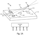
- FIG. 1A is a perspective view of an example of a system for characterizing aerosols.
- Sensor system 100 has first source 102, second source 104, first sensor 106, second sensor 108, and third sensor 110, which are depicted as located on surface 112.
- first source 102 is configured to emit first electromagnetic radiation pulse 114
- second source 104 is configured to emit second electromagnetic radiation pulse 116.
- first electromagnetic radiation pulse 114 and second electromagnetic radiation pulse 116 are aimed to illuminate and collide with aerosol particles 118, scattering first radiation pulse 114 and second electromagnetic radiation pulse 116.
- first radiation pulse 114 and second electromagnetic radiation pulse 116 are scattered by aerosol particles in all directions.
- some of the scattered electromagnetic radiation returns follow return path 122a, return path 122b, and return path 122c, and are received by first sensor 106, second sensor 108, and third sensor 110, respectively.
- First electromagnetic radiation pulse 114 has a first wavelength range and second electromagnetic radiation pulse 116 has a second wavelength range.
- the first wavelength range and second wavelength range are selected based on aerosol particle size. For example, longer wavelengths of electromagnetic radiation may be preferred for larger aerosol particles.
- first source 102 and second source 104 are configured such that first electromagnetic radiation pulse 114 or second electromagnetic wavelength pulse 116 has a wavelength range greater than or equal to 200 nm and less than or equal to 600 nm corresponding to the ultraviolet to orange visible light spectrum.
- At least one electromagnetic radiation return is received in step 308.
- the at least one electromagnetic radiation return is received by the first sensor and has the second wavelength range.
- the at least one electromagnetic radiation return is received by a second sensor that is spaced from the first sensor and is also connected to the processing device.
- the processing device is capable of determining at least one intensity based on the at least one electromagnetic radiation return.
- the algorithm is capable of using the plurality of ambient intensities and the intensities corresponding to the returns received in steps 304 and 308 to create corrected intensities.
- the algorithm is then capable of using the corrected intensities to determine the aerosol parameter.
- the algorithm may produce corrected intensities, for example, by subtracting the plurality of intensities corresponding to the ambient electromagnetic radiation received in steps 301 and 305 from the intensities corresponding to the electromagnetic radiation returns received in steps 304 and 306, respectively.
- the aerosol parameter is output in step 314.
- the aerosol parameter may be output by, for example, the processing device as a value. Where the processing device is connected to multiple sensors, the aerosol parameter may be output as, for example, an array of pixels.
- method 300 optionally includes steps of receiving a first ambient electromagnetic radiation and receiving a second ambient electromagnetic radiation.
- Method 300 can also be performed to characterize an aerosol having one or both of a known average particle diameter and a known concentration to create a training data array or training curves. For example, method 300 can be repeated to output a plurality of aerosol parameters where each aerosol parameter was determined at a known average particle size, a known concentration, and a known particle type.
- This plurality of aerosol parameters can be arranged by the processing device into, for example, an array.
- the array can be a three-dimensional array, wherein one axis is average particle size, one axis is concentration, and one axis is the aerosol parameter.
- the known aerosol parameters can be used to determine two-dimensional training curves.
- the aerosol parameter can be plotted as a function of concentration or of average diameter.
- aerosol parameters can be determined for aerosol particles having other known characteristics in addition to average particle size and concentration.
- the processing device can arrange the known characteristics and the aerosol parameters into a four-dimensional or a higher-dimensional array.
- the training data array or training curves can be used by the processing device in method 300 in conjunction with an algorithm, such as the algorithm used in step 312, to determine the average diameter or the concentration of an aerosol having an unknown average diameter, unknown concentration, or unknown particle type by comparing the aerosol parameter returned for the aerosol to the training data array or training curves.
- an algorithm such as the algorithm used in step 312
- method 300 can be performed to characterize any suitable aerosol.
- the aerosol is a water aerosol, such as a fog, a liquid water aerosol, or an ice crystal aerosol.
- the aerosol is another suitable aerosol or aerosolized particle, such as smoke, dust, bioaerosol, or ash.
- the aerosol may also be a salt aerosol, such as oil droplets surrounding NaCl particles.
- the first sensor and second sensor are configured with optical filters that filter out certain wavelengths of light.
- the sensors can be configured with filters that are selected to filter out ambient light but also transmit the wavelengths emitted by the first and second sources.
- the first sensor can be configured with an optical filter that selectively transmits the first wavelength range and the second sensor can be configured with an optical filter that selectively transmits the second wavelength range.
- step 302 and step 306 can occur simultaneously so that the aerosol particles are illuminated with the first electromagnetic radiation pulse and the second electromagnetic radiation pulse at the same time.
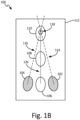
- the system used to perform method 300 has a first source, a second source, first sensor, a second sensor, and a processing device connected to each of sources and sensors.
- the sources and sensors may be disposed, for example, along a surface.
- the first source and second source may be disposed along an axis.
- the first sensor may, for example, be disposed along a medial plane that is located between the first and second sources. Generally, the medial plane is perpendicular to the axis.
- the first sensor is disposed at the intersection between the axis and the medial plane and the second sensor is disposed at another location along the medial plane.
Landscapes
- Chemical & Material Sciences (AREA)
- General Physics & Mathematics (AREA)
- Physics & Mathematics (AREA)
- Analytical Chemistry (AREA)
- Biochemistry (AREA)
- Life Sciences & Earth Sciences (AREA)
- Health & Medical Sciences (AREA)
- General Health & Medical Sciences (AREA)
- Immunology (AREA)
- Pathology (AREA)
- Business, Economics & Management (AREA)
- Emergency Management (AREA)
- Dispersion Chemistry (AREA)
- Investigating Or Analysing Materials By Optical Means (AREA)
Claims (12)
- Procédé de caractérisation d'un aérosol, le procédé comprenant :l'éclairage des particules d'aérosol (118) situées dans un volume de mesure avec une première impulsion de rayonnement électromagnétique (114) émise à partir d'une première source (102), dans lequel la première impulsion de rayonnement électromagnétique a une première plage de longueurs d'onde ;la réception d'un ou plusieurs premiers retours de rayonnement électromagnétique qui ont été diffusés par les particules d'aérosol éclairées par la première impulsion de rayonnement électromagnétique au niveau d'un ou de plusieurs capteurs ;l'éclairage des particules d'aérosol dans le volume de mesure avec une deuxième impulsion de rayonnement électromagnétique (116) émise à partir d'une deuxième source (104), dans lequel la deuxième impulsion de rayonnement électromagnétique ayant une deuxième plage de longueurs d'onde qui est différente de la première plage de longueurs d'onde ;la réception d'un ou plusieurs deuxièmes retours de rayonnement électromagnétique diffusés par les particules d'aérosol éclairées par la deuxième impulsion de rayonnement électromagnétique au niveau d'un ou de plusieurs capteurs (106, 108, 110) ; dans lequel la première source (102), la deuxième source (104) et les capteurs (106, 108, 110) sont disposés sur un extérieur d'une surface sensiblement plate (112) ou disposés dans des évidements à l'intérieur de la surface sensiblement plate (112) ; dans lequel les capteurs (106, 108, 110) comprennent un premier capteur (106), un deuxième capteur (108) et un troisième capteur (110) ; dans lequel le premier capteur (106), le deuxième capteur (108) et le troisième capteur (110) sont disposés le long d'un plan médian (126) qui se prolonge à l'opposé de la surface sensiblement plate (112) selon un angle normal à la surface sensiblement plate (112) ; et dans lequel la première source (102), la deuxième source (104) et le premier capteur (106) sont disposés le long d'un axe qui est perpendiculaire au plan médian (126) ;la détermination, à l'aide d'un dispositif de traitement (120), d'au moins une première intensité sur la base de l'un ou plusieurs retours de rayonnement électromagnétique reçus par l'un ou plusieurs capteurs ;la détermination, à l'aide du dispositif de traitement, d'au moins une deuxième intensité sur la base de l'un ou plusieurs retours de rayonnement électromagnétique reçus par l'un ou plusieurs capteurs ;la détermination, à l'aide du dispositif de traitement, d'un paramètre d'aérosol indicatif d'un diamètre moyen des particules d'aérosol, d'une concentration des particules d'aérosol, d'une phase des particules d'aérosol ou d'un type de particule des particules d'aérosol, dans lequel le paramètre d'aérosol est basé sur un algorithme avec un rapport égal à l'au moins une première intensité divisée par l'au moins une deuxième intensité, dans lequel l'algorithme compare l'au moins une première intensité, l'au moins une deuxième intensité et/ou le rapport avec des données d'apprentissage pour déterminer le paramètre d'aérosol, et dans lequel les données d'apprentissage comportent des mesures d'aérosols avec des concentrations connues, des tailles de particules moyennes connues, une phase connue et/ou un type de particule connu ; etla délivrance, par le dispositif de traitement, du paramètre d'aérosol permettant de caractériser l'aérosol.
- Procédé selon la revendication 1, dans lequel l'une ou les deux des première et deuxième plages de longueurs d'onde sont supérieures ou égales à 200 nm et inférieures ou égales à 600 nm, ou dans lequel l'une ou les deux des première et deuxième plages de longueurs d'onde sont supérieures ou égales à 600 nm et inférieures ou égales à 1200 nm, ou dans lequel l'une ou les deux des première et deuxième plages de longueurs d'onde sont supérieures ou égales à 1200 nm et inférieures ou égales à 6000 nm, ou dans lequel l'une ou les deux des première et deuxième plages de longueurs d'onde sont supérieures ou égales à 6000 nm et inférieures ou égales à 12000 nm.
- Procédé selon la revendication 1 ou 2, comprenant également :l'éclairage des particules d'aérosol situées dans le volume de mesure avec une troisième impulsion de rayonnement électromagnétique émise à partir d'une troisième source, dans lequel la troisième impulsion de rayonnement électromagnétique a une troisième plage de longueurs d'onde ;la réception, au niveau d'un ou de plusieurs capteurs, d'un ou plusieurs troisièmes retours de rayonnement électromagnétique diffusés par les particules d'aérosol illuminées par la troisième impulsion de rayonnement électromagnétique ;l'éclairage des particules d'aérosol situées dans un volume de mesure avec une quatrième impulsion de rayonnement électromagnétique émise à partir d'une quatrième source, dans lequel la quatrième impulsion de rayonnement électromagnétique a une quatrième plage de longueurs d'onde ;la réception d'un ou plusieurs capteurs, d'un ou plusieurs quatrièmes retours de rayonnement électromagnétique qui ont été diffusés par les particules d'aérosol éclairées par la quatrième impulsion de rayonnement électromagnétique ;la détermination, à l'aide du dispositif de traitement, d'au moins une troisième intensité sur la base de l'un ou plusieurs troisièmes retours de rayonnement électromagnétique reçus par l'un ou plusieurs capteurs ;la détermination, à l'aide du dispositif de traitement, d'au moins une quatrième intensité sur la base de l'un ou plusieurs quatrièmes retours de rayonnement électromagnétique reçus par l'un ou plusieurs capteurs ;la détermination, à l'aide du dispositif de traitement, d'un paramètre d'aérosol indicatif d'un diamètre moyen des particules d'aérosol ou d'une concentration des particules d'aérosol, le paramètre d'aérosol étant basé sur un algorithme qui compare l'au moins une première intensité, l'au moins une deuxième intensité, l'au moins une troisième intensité et l'au moins une quatrième intensité avec les données d'apprentissage ; etla délivrance, par le dispositif de traitement, du paramètre d'aérosol permettant de caractériser l'aérosol.
- Procédé selon une quelconque revendication précédente, et comprenant également :la répétition du procédé selon la revendication 1 pour délivrer une pluralité de paramètres d'aérosol, chaque paramètre d'aérosol de la pluralité de paramètres d'aérosol étant déterminé à un diamètre moyen connu, une concentration connue et un type de particule connu ; etla détermination, à l'aide du dispositif de traitement, d'un ensemble de données d'apprentissage indiquant les intensités respectives des retours de rayonnement électromagnétique diffusé en fonction du diamètre moyen mesuré, de la concentration mesurée, du type de particule mesuré.
- Procédé selon la revendication 4, et comprenant également :
la détermination de la taille ou de la concentration moyenne des particules en fonction de l'algorithme, de l'au moins une première intensité, de l'au moins une deuxième intensité et du tableau de données d'apprentissage. - Procédé selon une quelconque revendication précédente, et comprenant également :la réception d'une première pluralité de rayonnement électromagnétique ambiant à l'aide de l'un ou de plusieurs capteurs avant d'éclairer les particules d'aérosol avec la première impulsion de rayonnement électromagnétique ;la détermination, à l'aide du dispositif de traitement, d'une première pluralité d'intensités ambiantes sur la base de la première pluralité de rayonnements électromagnétiques ambiants ;la réception d'une seconde pluralité de rayonnement électromagnétique ambiant à l'aide de l'un ou de plusieurs capteurs avant d'éclairer les particules d'aérosol avec la deuxième impulsion de rayonnement électromagnétique ;la détermination, à l'aide du dispositif de traitement, d'une seconde pluralité d'intensités ambiantes sur la base de la seconde pluralité de rayonnements électromagnétiques ambiants ;la détermination, à l'aide du dispositif de traitement, d'un paramètre d'aérosol indicatif d'un diamètre moyen des particules d'aérosol ou d'une concentration des particules d'aérosol, le paramètre d'aérosol étant basé sur l'algorithme, l'au moins une première intensité, l'au moins une deuxième intensité, la première pluralité d'intensités ambiantes et la seconde pluralité d'intensités ambiantes ; etla délivrance, à l'aide du dispositif de traitement, du paramètre d'aérosol permettant de caractériser l'aérosol.
- Procédé selon la revendication 6, dans lequel l'éclairage des particules d'aérosol avec la première impulsion de rayonnement électromagnétique et la réception du premier retour de rayonnement électromagnétique sont effectués avant de recevoir le second rayonnement électromagnétique ambiant.
- Procédé selon une quelconque revendication précédente, dans lequel les particules d'aérosol sont des particules d'aérosol d'eau liquide, des particules d'aérosol de glace, des particules de fumée, des particules de poussière, des particules de bioaérosol, des particules de cendres ou des particules d'aérosol de sel.
- Système de caractérisation d'un aérosol, le système comprenant :une première source (102) configurée pour émettre une première impulsion de rayonnement électromagnétique (114) (118) avec la première impulsion électromagnétique, dans lequel la première impulsion de rayonnement électromagnétique a une première plage de longueurs d'onde ;une deuxième source (104) configurée pour émettre une deuxième impulsion de rayonnement électromagnétique (116) et éclairer les particules d'aérosol avec la deuxième impulsion électromagnétique, dans lequel la deuxième impulsion de rayonnement électromagnétique a une deuxième plage de longueurs d'onde qui est différente de la première plage de longueurs d'onde ;un ou plusieurs capteurs (106, 108, 110) configurés pour recevoir un ou plusieurs premiers retours de rayonnement électromagnétique, un ou plusieurs seconds retours de rayonnement électromagnétique, ou une combinaison d'un ou plusieurs premiers retours de rayonnement électromagnétique et d'un ou plusieurs seconds retours de rayonnement électromagnétique, dans lequel l'un ou plusieurs premiers retours de rayonnement électromagnétique sont diffusés par les particules d'aérosol éclairées par la première impulsion de rayonnement électromagnétique et l'un ou plusieurs seconds retours de rayonnement électromagnétique sont diffusés par les particules d'aérosol éclairées par la deuxième impulsion de rayonnement électromagnétique ; dans lequel la première source (102), la deuxième source (104) et l'un ou plusieurs capteurs (106, 108, 110) sont disposés sur un extérieur d'une surface sensiblement plate (112) ou disposés dans des évidements à l'intérieur de la surface sensiblement plate (112) ; dans lequel l'un ou plusieurs capteurs (106, 108, 110) comprennent un premier capteur (106), un deuxième capteur (108) et un troisième capteur (110) ; dans lequel le premier capteur (106), le deuxième capteur (108) et le troisième capteur (110) sont disposés le long d'un plan médian (126) qui se prolonge à l'écart de la surface sensiblement plate (112) selon un angle normal à la surface sensiblement plate (112) ; et dans lequel la première source (102), la deuxième source (104) et le premier capteur (106) sont disposés le long d'un axe qui est perpendiculaire au plan médian (126) ;au moins un processeur (120) ; etune mémoire lisible par ordinateur codée avec des instructions qui, lorsqu'elles sont exécutées par l'au moins un processeur, amènent le système à :éclairer des particules d'aérosol situées dans un volume de mesure avec la première impulsion de rayonnement électromagnétique ;recevoir l'un ou plusieurs premiers retours de rayonnement électromagnétique au niveau de l'un ou de plusieurs capteurs ;éclairer les particules d'aérosol dans le volume de mesure avec la deuxième impulsion de rayonnement électromagnétique ;recevoir l'un ou plusieurs seconds retours de rayonnement électromagnétique au niveau de l'un ou de plusieurs capteurs ;déterminer au moins une première intensité sur la base d'un ou de plusieurs premiers retours de rayonnement électromagnétique reçus par un ou plusieurs capteurs ;déterminer au moins une deuxième intensité sur la base de l'un ou plusieurs seconds retours de rayonnement électromagnétique reçus par l'un ou plusieurs capteurs ;déterminer un paramètre d'aérosol indicatif d'un diamètre moyen des particules d'aérosol ou une concentration des particules d'aérosol, dans lequel le paramètre d'aérosol est basé sur un algorithme qui compare l'au moins l'au moins une première intensité, l'au moins une deuxième intensité et/ou le rapport avec l'au moins l'au moins une première intensité et l'au moins une deuxième intensité avec des données d'apprentissage pour déterminer le paramètre d'aérosol, et dans lequel les données d'apprentissage comportent des mesures d'aérosols avec des concentrations connues, des tailles de particules moyennes connues, une phase connue et/ou un type de particule connu ; etgénérer le paramètre d'aérosol pour caractériser l'aérosol.
- Système selon la revendication 9, dans lequel le premier capteur (106) est situé entre la première source (102) et la deuxième source (104).
- Système selon la revendication 10, dans lequel le premier capteur (106) est disposé à l'intersection entre le plan médian et l'axe se prolongeant de la première source à la deuxième source.
- Système selon la revendication 9, 10 ou 11,
dans lequel le deuxième capteur (108) est espacé du premier capteur (106) d'une distance le long du plan médian (126).
Applications Claiming Priority (1)
| Application Number | Priority Date | Filing Date | Title |
|---|---|---|---|
| US16/536,970 US10950108B2 (en) | 2019-08-09 | 2019-08-09 | Characterization of aerosols |
Publications (2)
| Publication Number | Publication Date |
|---|---|
| EP3772642A1 EP3772642A1 (fr) | 2021-02-10 |
| EP3772642B1 true EP3772642B1 (fr) | 2025-04-09 |
Family
ID=68771469
Family Applications (1)
| Application Number | Title | Priority Date | Filing Date |
|---|---|---|---|
| EP19213484.9A Active EP3772642B1 (fr) | 2019-08-09 | 2019-12-04 | Caractérisation d'aérosols |
Country Status (3)
| Country | Link |
|---|---|
| US (1) | US10950108B2 (fr) |
| EP (1) | EP3772642B1 (fr) |
| CA (1) | CA3062686A1 (fr) |
Families Citing this family (1)
| Publication number | Priority date | Publication date | Assignee | Title |
|---|---|---|---|---|
| CN114354460B (zh) * | 2021-12-29 | 2023-09-22 | 中国科学院合肥物质科学研究院 | 可快速实时测量气溶胶液态水的高精度测量系统及方法 |
Citations (1)
| Publication number | Priority date | Publication date | Assignee | Title |
|---|---|---|---|---|
| US20110194111A1 (en) * | 2008-10-09 | 2011-08-11 | Hochiki Corporation | Smoke detector |
Family Cites Families (31)
| Publication number | Priority date | Publication date | Assignee | Title |
|---|---|---|---|---|
| US3914616A (en) | 1974-08-05 | 1975-10-21 | Joseph Mooibroek | Smoke detector |
| US5000566A (en) * | 1990-01-05 | 1991-03-19 | Lockheed Sanders, Inc. | Optical velocimeter |
| US5400014A (en) | 1993-07-12 | 1995-03-21 | Detection Systems, Inc. | Smoke detector with dark chamber |
| US6064430A (en) | 1995-12-11 | 2000-05-16 | Slc Technologies Inc. | Discrete surveillance camera devices |
| US6876305B2 (en) | 1999-12-08 | 2005-04-05 | Gentex Corporation | Compact particle sensor |
| DE10036860A1 (de) | 2000-07-28 | 2002-02-07 | Basf Ag | Verfahren und Vorrichtung zur Bestimmung von physikalischen Kollektivparametern von Partikeln in Gasen |
| US20030046880A1 (en) | 2001-09-10 | 2003-03-13 | Andrew Brown | Egg shaped house |
| US6841778B1 (en) | 2001-11-09 | 2005-01-11 | Environmental Systems Products Holdings Inc. | Method and apparatus for measuring particulates in vehicle emissions |
| DE10246756B4 (de) | 2002-10-07 | 2006-03-16 | Novar Gmbh | Branderkennungsverfahren und Brandmelder zu dessen Durchführung |
| JP4598766B2 (ja) * | 2003-04-29 | 2010-12-15 | エス3アイ, エル エル シィ | 生物学的微粒子及び非生物学的微粒子を検出し且つ分類するためのマルチスペクトル光学方法及びシステム |
| AU2004290246B2 (en) | 2003-11-17 | 2010-06-10 | Hochiki Corporation | Smoke sensor using scattering light |
| GB2423357A (en) | 2005-02-22 | 2006-08-23 | Thorn Security | A self-monitoring smoke detector |
| CN100554944C (zh) | 2005-04-30 | 2009-10-28 | 中国科学院安徽光学精密机械研究所 | 实验室烟(水)雾brdf测量方法 |
| US7932490B2 (en) * | 2007-08-07 | 2011-04-26 | Tsi, Inc. | Size segregated aerosol mass concentration measurement device |
| EP2331938A4 (fr) | 2008-09-05 | 2017-05-17 | Xtralis Technologies Ltd | Détection optique de caractéristiques de particules |
| FR2964743B1 (fr) | 2010-09-14 | 2015-06-26 | Finsecur | Circuit de detection de fumee, detecteur de fumee le comportant et dispositif d'alarme les comportant. |
| DE102011119431C5 (de) * | 2011-11-25 | 2018-07-19 | Apparatebau Gauting Gmbh | Streustrahlungsbrandmelder und Verfahren zur automatischen Erkennung einer Brandsituation |
| KR20130078252A (ko) | 2011-12-30 | 2013-07-10 | (주)다온씨앤티 | 광센서를 이용한 안개감지 장치 |
| RU2500998C2 (ru) | 2012-03-14 | 2013-12-10 | Государственное образовательное учреждение высшего профессионального образования "Алтайский государственный технический университет им. И.И. Ползунова" (АлтГТУ) | Способ калибровки оптической измерительной аппаратуры при оценке среднего диаметра дисперсных частиц |
| US9140646B2 (en) | 2012-04-29 | 2015-09-22 | Valor Fire Safety, Llc | Smoke detector with external sampling volume using two different wavelengths and ambient light detection for measurement correction |
| US8907802B2 (en) | 2012-04-29 | 2014-12-09 | Valor Fire Safety, Llc | Smoke detector with external sampling volume and ambient light rejection |
| EP2775465B1 (fr) | 2013-03-06 | 2017-08-16 | Siemens Schweiz AG | Alarme dotée d'un capteur de rayonnement infrarouge, destiné aussi bien à la détection du feu ouvert qu'à la détermination d'une température ambiante |
| KR20160079057A (ko) | 2013-10-30 | 2016-07-05 | 발로르 파이어 세이프티, 엘엘씨 | 외부 샘플링 볼륨 및 주변광 배제를 갖는 연기 감지기 |
| CN103558187A (zh) | 2013-11-02 | 2014-02-05 | 中国工程物理研究院流体物理研究所 | 水雾浓度测量装置及测量方法 |
| CN103994954B (zh) | 2014-05-13 | 2016-08-24 | 中国科学技术大学先进技术研究院 | 一种雾霾测量仪 |
| CN103983544B (zh) * | 2014-05-28 | 2015-12-30 | 南京大学 | 多通道气溶胶散射吸收测量仪 |
| EP3029647B1 (fr) | 2014-12-04 | 2017-05-31 | Siemens Schweiz AG | Détecteur de fumée à écran diffusant ouvert, notamment équipé d'une LED Side-looker |
| CN104392577B (zh) | 2014-12-08 | 2016-08-31 | 王殊 | 一种基于双波长散射信号的气溶胶粒径传感方法 |
| CN108291863B (zh) * | 2015-10-02 | 2020-07-03 | 国家光学研究所 | 用于使用光散射技术进行个体颗粒尺寸测量的系统和方法 |
| CN106769923B (zh) | 2016-11-28 | 2019-05-14 | 浙江大学 | 一种基于激光吸收及散射的水蒸气冷凝特性测量装置 |
| WO2019034821A1 (fr) | 2017-08-16 | 2019-02-21 | Rainbowvision | Equipement de caracterisation d'un brouillard de gouttelettes, application pour le contrôle de qualite et la detection de givrage |
-
2019
- 2019-08-09 US US16/536,970 patent/US10950108B2/en active Active
- 2019-11-25 CA CA3062686A patent/CA3062686A1/fr active Pending
- 2019-12-04 EP EP19213484.9A patent/EP3772642B1/fr active Active
Patent Citations (1)
| Publication number | Priority date | Publication date | Assignee | Title |
|---|---|---|---|---|
| US20110194111A1 (en) * | 2008-10-09 | 2011-08-11 | Hochiki Corporation | Smoke detector |
Also Published As
| Publication number | Publication date |
|---|---|
| EP3772642A1 (fr) | 2021-02-10 |
| US10950108B2 (en) | 2021-03-16 |
| CA3062686A1 (fr) | 2021-02-09 |
| US20210043056A1 (en) | 2021-02-11 |
| BR102019026652A2 (pt) | 2021-02-23 |
Similar Documents
| Publication | Publication Date | Title |
|---|---|---|
| US20170010197A1 (en) | Method and device for determining characteristic properties of a transparent particle | |
| CN101858864B (zh) | 用于干粉剂的校准系统 | |
| US10337996B2 (en) | Lidar instrument and method of operation | |
| EP3482216A1 (fr) | Systèmes et procédés de données aériennes optiques | |
| CN116679320B (zh) | 一种气溶胶和风场的同时测量方法、装置、设备及介质 | |
| EP2843394A1 (fr) | Capteur et procédé pour mesure de turbidité | |
| JPS58150867A (ja) | 遠隔の位置にある物体の3次元速度の測定装置 | |
| CN110006848A (zh) | 一种获取气溶胶消光系数的方法和装置 | |
| EP3772642B1 (fr) | Caractérisation d'aérosols | |
| JPH11287755A (ja) | 散乱吸収体の吸収成分の濃度計測方法及び装置 | |
| WO2014193899A1 (fr) | Calibreuse de gouttelettes de pulvérisation | |
| CN109164466A (zh) | 用于测量温度湿度廓线的激光雷达系统 | |
| JP4398819B2 (ja) | 表面特性を特定するための方法および装置 | |
| US8514378B2 (en) | Method of optical teledetection of compounds in a medium | |
| US3632209A (en) | System for measuring light transmittance through absorptive or diffusive media | |
| BR102019026652B1 (pt) | Método e sistema óptico para caracterizar um aerossol | |
| US11827365B2 (en) | Detection of aircraft icing conditions and discrimination between liquid droplets and ice crystals | |
| CN209044062U (zh) | 用于测量温度湿度廓线的激光雷达系统 | |
| Werner | Slant range visibility determination from lidar signatures by the two-point method | |
| CN116184436A (zh) | 阵列轨道角动量穿云透雾量子探测成像系统 | |
| Leonard et al. | A single-ended atmospheric transmissometer | |
| CN114047101A (zh) | 一种颗粒物不规则程度表征的光学模拟系统及方法 | |
| Gurvich et al. | Impact of pitch angle fluctuations on airborne lidar forward sensing along the flight direction | |
| Nicolae et al. | Benefits and drawbacks of laser remote sensing in atmospheric research | |
| CN120176852B (zh) | 一种模拟多能见度的主被动偏振传输特性测试装置及方法 |
Legal Events
| Date | Code | Title | Description |
|---|---|---|---|
| PUAI | Public reference made under article 153(3) epc to a published international application that has entered the european phase |
Free format text: ORIGINAL CODE: 0009012 |
|
| STAA | Information on the status of an ep patent application or granted ep patent |
Free format text: STATUS: THE APPLICATION HAS BEEN PUBLISHED |
|
| AK | Designated contracting states |
Kind code of ref document: A1 Designated state(s): AL AT BE BG CH CY CZ DE DK EE ES FI FR GB GR HR HU IE IS IT LI LT LU LV MC MK MT NL NO PL PT RO RS SE SI SK SM TR |
|
| AX | Request for extension of the european patent |
Extension state: BA ME |
|
| STAA | Information on the status of an ep patent application or granted ep patent |
Free format text: STATUS: REQUEST FOR EXAMINATION WAS MADE |
|
| 17P | Request for examination filed |
Effective date: 20210810 |
|
| RBV | Designated contracting states (corrected) |
Designated state(s): AL AT BE BG CH CY CZ DE DK EE ES FI FR GB GR HR HU IE IS IT LI LT LU LV MC MK MT NL NO PL PT RO RS SE SI SK SM TR |
|
| STAA | Information on the status of an ep patent application or granted ep patent |
Free format text: STATUS: EXAMINATION IS IN PROGRESS |
|
| 17Q | First examination report despatched |
Effective date: 20230105 |
|
| GRAP | Despatch of communication of intention to grant a patent |
Free format text: ORIGINAL CODE: EPIDOSNIGR1 |
|
| STAA | Information on the status of an ep patent application or granted ep patent |
Free format text: STATUS: GRANT OF PATENT IS INTENDED |
|
| INTG | Intention to grant announced |
Effective date: 20241112 |
|
| GRAS | Grant fee paid |
Free format text: ORIGINAL CODE: EPIDOSNIGR3 |
|
| GRAA | (expected) grant |
Free format text: ORIGINAL CODE: 0009210 |
|
| STAA | Information on the status of an ep patent application or granted ep patent |
Free format text: STATUS: THE PATENT HAS BEEN GRANTED |
|
| AK | Designated contracting states |
Kind code of ref document: B1 Designated state(s): AL AT BE BG CH CY CZ DE DK EE ES FI FR GB GR HR HU IE IS IT LI LT LU LV MC MK MT NL NO PL PT RO RS SE SI SK SM TR |
|
| REG | Reference to a national code |
Ref country code: GB Ref legal event code: FG4D |
|
| REG | Reference to a national code |
Ref country code: CH Ref legal event code: EP |
|
| REG | Reference to a national code |
Ref country code: DE Ref legal event code: R096 Ref document number: 602019068358 Country of ref document: DE |
|
| REG | Reference to a national code |
Ref country code: IE Ref legal event code: FG4D |
|
| REG | Reference to a national code |
Ref country code: NL Ref legal event code: MP Effective date: 20250409 |
|
| PG25 | Lapsed in a contracting state [announced via postgrant information from national office to epo] |
Ref country code: NL Free format text: LAPSE BECAUSE OF FAILURE TO SUBMIT A TRANSLATION OF THE DESCRIPTION OR TO PAY THE FEE WITHIN THE PRESCRIBED TIME-LIMIT Effective date: 20250409 |
|
| REG | Reference to a national code |
Ref country code: AT Ref legal event code: MK05 Ref document number: 1783921 Country of ref document: AT Kind code of ref document: T Effective date: 20250409 |
|
| PG25 | Lapsed in a contracting state [announced via postgrant information from national office to epo] |
Ref country code: PT Free format text: LAPSE BECAUSE OF FAILURE TO SUBMIT A TRANSLATION OF THE DESCRIPTION OR TO PAY THE FEE WITHIN THE PRESCRIBED TIME-LIMIT Effective date: 20250811 Ref country code: FI Free format text: LAPSE BECAUSE OF FAILURE TO SUBMIT A TRANSLATION OF THE DESCRIPTION OR TO PAY THE FEE WITHIN THE PRESCRIBED TIME-LIMIT Effective date: 20250409 Ref country code: ES Free format text: LAPSE BECAUSE OF FAILURE TO SUBMIT A TRANSLATION OF THE DESCRIPTION OR TO PAY THE FEE WITHIN THE PRESCRIBED TIME-LIMIT Effective date: 20250409 |
|
| REG | Reference to a national code |
Ref country code: LT Ref legal event code: MG9D |
|
| PG25 | Lapsed in a contracting state [announced via postgrant information from national office to epo] |
Ref country code: NO Free format text: LAPSE BECAUSE OF FAILURE TO SUBMIT A TRANSLATION OF THE DESCRIPTION OR TO PAY THE FEE WITHIN THE PRESCRIBED TIME-LIMIT Effective date: 20250709 Ref country code: GR Free format text: LAPSE BECAUSE OF FAILURE TO SUBMIT A TRANSLATION OF THE DESCRIPTION OR TO PAY THE FEE WITHIN THE PRESCRIBED TIME-LIMIT Effective date: 20250710 |
|
| PG25 | Lapsed in a contracting state [announced via postgrant information from national office to epo] |
Ref country code: PL Free format text: LAPSE BECAUSE OF FAILURE TO SUBMIT A TRANSLATION OF THE DESCRIPTION OR TO PAY THE FEE WITHIN THE PRESCRIBED TIME-LIMIT Effective date: 20250409 |
|
| PG25 | Lapsed in a contracting state [announced via postgrant information from national office to epo] |
Ref country code: BG Free format text: LAPSE BECAUSE OF FAILURE TO SUBMIT A TRANSLATION OF THE DESCRIPTION OR TO PAY THE FEE WITHIN THE PRESCRIBED TIME-LIMIT Effective date: 20250409 |
|
| PG25 | Lapsed in a contracting state [announced via postgrant information from national office to epo] |
Ref country code: HR Free format text: LAPSE BECAUSE OF FAILURE TO SUBMIT A TRANSLATION OF THE DESCRIPTION OR TO PAY THE FEE WITHIN THE PRESCRIBED TIME-LIMIT Effective date: 20250409 |
|
| PG25 | Lapsed in a contracting state [announced via postgrant information from national office to epo] |
Ref country code: AT Free format text: LAPSE BECAUSE OF FAILURE TO SUBMIT A TRANSLATION OF THE DESCRIPTION OR TO PAY THE FEE WITHIN THE PRESCRIBED TIME-LIMIT Effective date: 20250409 |
|
| PG25 | Lapsed in a contracting state [announced via postgrant information from national office to epo] |
Ref country code: RS Free format text: LAPSE BECAUSE OF FAILURE TO SUBMIT A TRANSLATION OF THE DESCRIPTION OR TO PAY THE FEE WITHIN THE PRESCRIBED TIME-LIMIT Effective date: 20250709 |
|
| PG25 | Lapsed in a contracting state [announced via postgrant information from national office to epo] |
Ref country code: IS Free format text: LAPSE BECAUSE OF FAILURE TO SUBMIT A TRANSLATION OF THE DESCRIPTION OR TO PAY THE FEE WITHIN THE PRESCRIBED TIME-LIMIT Effective date: 20250809 |
|
| PG25 | Lapsed in a contracting state [announced via postgrant information from national office to epo] |
Ref country code: LV Free format text: LAPSE BECAUSE OF FAILURE TO SUBMIT A TRANSLATION OF THE DESCRIPTION OR TO PAY THE FEE WITHIN THE PRESCRIBED TIME-LIMIT Effective date: 20250409 |
|
| PGFP | Annual fee paid to national office [announced via postgrant information from national office to epo] |
Ref country code: DE Payment date: 20251126 Year of fee payment: 7 |
|
| PGFP | Annual fee paid to national office [announced via postgrant information from national office to epo] |
Ref country code: GB Payment date: 20251119 Year of fee payment: 7 |
|
| REG | Reference to a national code |
Ref country code: DE Ref legal event code: R097 Ref document number: 602019068358 Country of ref document: DE |
|
| PG25 | Lapsed in a contracting state [announced via postgrant information from national office to epo] |
Ref country code: SM Free format text: LAPSE BECAUSE OF FAILURE TO SUBMIT A TRANSLATION OF THE DESCRIPTION OR TO PAY THE FEE WITHIN THE PRESCRIBED TIME-LIMIT Effective date: 20250409 Ref country code: DK Free format text: LAPSE BECAUSE OF FAILURE TO SUBMIT A TRANSLATION OF THE DESCRIPTION OR TO PAY THE FEE WITHIN THE PRESCRIBED TIME-LIMIT Effective date: 20250409 |
|
| PGFP | Annual fee paid to national office [announced via postgrant information from national office to epo] |
Ref country code: FR Payment date: 20251120 Year of fee payment: 7 |
|
| PG25 | Lapsed in a contracting state [announced via postgrant information from national office to epo] |
Ref country code: CZ Free format text: LAPSE BECAUSE OF FAILURE TO SUBMIT A TRANSLATION OF THE DESCRIPTION OR TO PAY THE FEE WITHIN THE PRESCRIBED TIME-LIMIT Effective date: 20250409 |
|
| PG25 | Lapsed in a contracting state [announced via postgrant information from national office to epo] |
Ref country code: EE Free format text: LAPSE BECAUSE OF FAILURE TO SUBMIT A TRANSLATION OF THE DESCRIPTION OR TO PAY THE FEE WITHIN THE PRESCRIBED TIME-LIMIT Effective date: 20250409 |
|
| PG25 | Lapsed in a contracting state [announced via postgrant information from national office to epo] |
Ref country code: RO Free format text: LAPSE BECAUSE OF FAILURE TO SUBMIT A TRANSLATION OF THE DESCRIPTION OR TO PAY THE FEE WITHIN THE PRESCRIBED TIME-LIMIT Effective date: 20250409 Ref country code: SK Free format text: LAPSE BECAUSE OF FAILURE TO SUBMIT A TRANSLATION OF THE DESCRIPTION OR TO PAY THE FEE WITHIN THE PRESCRIBED TIME-LIMIT Effective date: 20250409 |
|
| PG25 | Lapsed in a contracting state [announced via postgrant information from national office to epo] |
Ref country code: IT Free format text: LAPSE BECAUSE OF FAILURE TO SUBMIT A TRANSLATION OF THE DESCRIPTION OR TO PAY THE FEE WITHIN THE PRESCRIBED TIME-LIMIT Effective date: 20250409 |
|
| PLBE | No opposition filed within time limit |
Free format text: ORIGINAL CODE: 0009261 |
|
| STAA | Information on the status of an ep patent application or granted ep patent |
Free format text: STATUS: NO OPPOSITION FILED WITHIN TIME LIMIT |
|
| REG | Reference to a national code |
Ref country code: CH Ref legal event code: L10 Free format text: ST27 STATUS EVENT CODE: U-0-0-L10-L00 (AS PROVIDED BY THE NATIONAL OFFICE) Effective date: 20260218 |
|
| 26N | No opposition filed |
Effective date: 20260112 |