EP3772636A1 - Compteur et procédé de mesure du niveau d'un liquide - Google Patents
Compteur et procédé de mesure du niveau d'un liquide Download PDFInfo
- Publication number
- EP3772636A1 EP3772636A1 EP20189345.0A EP20189345A EP3772636A1 EP 3772636 A1 EP3772636 A1 EP 3772636A1 EP 20189345 A EP20189345 A EP 20189345A EP 3772636 A1 EP3772636 A1 EP 3772636A1
- Authority
- EP
- European Patent Office
- Prior art keywords
- meter
- probing
- phase shift
- liquid
- determining
- Prior art date
- Legal status (The legal status is an assumption and is not a legal conclusion. Google has not performed a legal analysis and makes no representation as to the accuracy of the status listed.)
- Granted
Links
Images


Classifications
-
- G—PHYSICS
- G01—MEASURING; TESTING
- G01F—MEASURING VOLUME, VOLUME FLOW, MASS FLOW OR LIQUID LEVEL; METERING BY VOLUME
- G01F23/00—Indicating or measuring liquid level or level of fluent solid material, e.g. indicating in terms of volume or indicating by means of an alarm
- G01F23/80—Arrangements for signal processing
- G01F23/802—Particular electronic circuits for digital processing equipment
-
- G—PHYSICS
- G01—MEASURING; TESTING
- G01F—MEASURING VOLUME, VOLUME FLOW, MASS FLOW OR LIQUID LEVEL; METERING BY VOLUME
- G01F23/00—Indicating or measuring liquid level or level of fluent solid material, e.g. indicating in terms of volume or indicating by means of an alarm
- G01F23/22—Indicating or measuring liquid level or level of fluent solid material, e.g. indicating in terms of volume or indicating by means of an alarm by measuring physical variables, other than linear dimensions, pressure or weight, dependent on the level to be measured, e.g. by difference of heat transfer of steam or water
- G01F23/26—Indicating or measuring liquid level or level of fluent solid material, e.g. indicating in terms of volume or indicating by means of an alarm by measuring physical variables, other than linear dimensions, pressure or weight, dependent on the level to be measured, e.g. by difference of heat transfer of steam or water by measuring variations of capacity or inductance of capacitors or inductors arising from the presence of liquid or fluent solid material in the electric or electromagnetic fields
- G01F23/263—Indicating or measuring liquid level or level of fluent solid material, e.g. indicating in terms of volume or indicating by means of an alarm by measuring physical variables, other than linear dimensions, pressure or weight, dependent on the level to be measured, e.g. by difference of heat transfer of steam or water by measuring variations of capacity or inductance of capacitors or inductors arising from the presence of liquid or fluent solid material in the electric or electromagnetic fields by measuring variations in capacitance of capacitors
- G01F23/266—Indicating or measuring liquid level or level of fluent solid material, e.g. indicating in terms of volume or indicating by means of an alarm by measuring physical variables, other than linear dimensions, pressure or weight, dependent on the level to be measured, e.g. by difference of heat transfer of steam or water by measuring variations of capacity or inductance of capacitors or inductors arising from the presence of liquid or fluent solid material in the electric or electromagnetic fields by measuring variations in capacitance of capacitors measuring circuits therefor
-
- G—PHYSICS
- G01—MEASURING; TESTING
- G01F—MEASURING VOLUME, VOLUME FLOW, MASS FLOW OR LIQUID LEVEL; METERING BY VOLUME
- G01F23/00—Indicating or measuring liquid level or level of fluent solid material, e.g. indicating in terms of volume or indicating by means of an alarm
- G01F23/80—Arrangements for signal processing
-
- G—PHYSICS
- G01—MEASURING; TESTING
- G01F—MEASURING VOLUME, VOLUME FLOW, MASS FLOW OR LIQUID LEVEL; METERING BY VOLUME
- G01F25/00—Testing or calibration of apparatus for measuring volume, volume flow or liquid level or for metering by volume
- G01F25/20—Testing or calibration of apparatus for measuring volume, volume flow or liquid level or for metering by volume of apparatus for measuring liquid level
Definitions
- the present invention relates to a meter and process for measuring the level of a liquid for example contained in a container.
- the meter and the related installation process, use and operation are particularly suitable for measuring the level of fuels or other flammable liquids with a high degree of safety against fires and detonations, for example for measuring the level of the fuel in the tanks of airplanes and other aircraft.
- the two plates are radially separated from one another by a cavity having annular-shaped cross sections.
- Such a cylindrical electric capacitor is arranged vertically in the tank so that as the level thereof changes the fuel rises more or less along the cavity that separates the two plates, thus changing the capacity of the capacitor.
- a purpose of the present invention is to avoid the aforementioned drawbacks and in particular to provide a meter and a process for measuring the level or the presence of a liquid in a tank or other container, which is more reliable and less dangerous than the devices and processes according to the state of the art.
- the signal generator (9) is configured to generate a substantially periodic probing signal, with a frequency preferably comprised between 5-30 Megahertz.
- such a process comprises the operation of determining the level of the liquid bath in the container based on the determinations of the time of flight and/or of the phase shift undergone by the probing signal obtained with the operation S 13.4).
- the liquid is selected from the following group: petrol, kerosene, diesel, a petroleum distillate, a mixture of hydrocarbons, water or an aqueous mixture, a fuel, liquid oxygen or hydrogen.
- Figures 1, 1A , 2 relate to a meter, indicated with overall reference numeral 1, for measuring the level of a liquid in a tank, cistern or other container S according to a first particular embodiment of the present invention.
- the liquid can for example be petrol, kerosene, diesel fuel or other fuel for airplanes, helicopters or other aircraft, missiles, automobiles, trucks or other land vehicles.
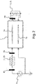
- the meter 1 comprises a logic unit 3, a signal generator 9 and a sensitive body 5; the latter comprises a power and/or transmission line 7 which in turn comprises at least two probing conductors 7 a, 7 b.
- the logic unit 3 can comprise for example a microprocessor unit.
- Each of such probing conductors 7 a, 7 b can for example be a wire or a track of an electrically conductive material; the track can for example be printed, glued, soldered or made by 3 D printing or through other additive production techniques ( additive manufacturing ) on an electrically insulating support, like for example a plate of Vetronite or other glass fibre.
- Such an electrically insulating support can also be very flexible and pliable.
- the power and/or transmission line 7 forms a downstream end 72 and an upstream end 70.
- upstream end 70 and downstream end 72 in the present description are meant to indicate the ends of the conductors 7 a, 7 b respectively closest to and furthest from the signal generator 9 described hereinafter.
- Each of the at least two probing conductors 7 a, 7 b extends between the upstream and downstream ends 70 and 72.
- the signal generator 9 can for example comprise an electric power supply.
- the signal generator 9 is configured for supplying with power the power and/or transmission line 7 with a probing signal, which is preferably a periodic signal.
- the probing signal is a sinusoidal periodic signal, having a square or triangular wave or a sum of sinusoidal fundamental frequency signals even different from one another.
- the logic unit 3 is configured for carrying out the following operations:
- the logic unit 3 is configured for determining, based on said phase shift, an electrical capacity equivalent to and/or influenced by at least one part of the meter (1) itself and/or the liquid in which the at least two probing conductors ( 7 a, 7 b) are dipped.
- phase shift of the probing signal is meant to indicate a delay that can even be equal to or greater than one or more periods of the probing signal initially generated and fed in the line 7; such a delay can be measured in the time domain even as a delay between two non-periodic signals.
- the meter 1 is provided with a first measurement electrical load 11 fed by at least one power line 7 and provided with a predetermined upstream measurement impedance ZS.
- the first measurement electrical load 11 powers at least one of the probing conductors 7 a, 7 b.
- the upstream measurement impedance ZS is comprised between about 20-300 Ohm, or between 30-200 Ohm, or between 100-120 Ohm, between 90-130 Ohm, between 90-105 Ohm or between 90-110 Ohm.
- the upstream measurement impedance ZS is preferably purely resistive, i.e. made with one or more resistors.
- the lowest frequency pole of the transfer function of the system comprising the first 11 and the possible second measurement electrical load 13 and the power line 7, or more generally the lowest frequency electrical pole of the meter 1, is advantageously comprised between 1-100 Megahertz, more preferably comprised between 1-30 megahertz, and even more preferably comprised between 10-20 megahertz or between 12-18 megahertz or roughly equal to 15 megahertz.
- the first measurement electrical load 11 sufficiently increases the impedance of the power supply 9, which is often too low if it is a commercial component, allowing the system be adapted - i.e. causing it to operate in impedance adaptation conditions or close thereto - and increasing the precision of the measurement of the level of the liquid.
- the meter 1 is provided with a# second measurement electrical load 13 powered by the at least one power line 7 and provided with a predetermined downstream measurement impedance ZL.
- the second measurement electrical load 13 is preferably powered by the downstream end of at least one of the probing conductors 7 a, 7 b.
- the downstream measurement impedance ZL has the same values as the upstream measurement impedance ZS.
- the two impedances ZS and ZL are selected so as to allow the meter to operate in impedance adaptation conditions, i.e. ensuring that the sum of the impedances ZS and of the signal generator 9, and the impedance ZL of the second measurement load 11 are substantially equal to or almost equal to the characteristic impedance of the power and/or transmission line section 7 that extends between the first 11 and the second measurement electrical load 13.
- substantially equal to or almost equal to the impedance of the power and/or transmission line section 7 is meant to indicate that the sum of the impedances ZS and of the signal generator 9, and the impedance ZL of the second measurement load 11 are substantially equal to the impedance of the aforementioned power and/or transmission line section 7 with a tolerance equal to or less than +- 20 % - and more preferably equal to or less than +- 10 % - of the modulus and of the specific impedance of the power and/or transmission line section 7 considered above.
- the impedance adaptation condition makes it possible to maximise the power of the signal detected in the measurement points PA and PB, improving the precision, the repeatability and more generally the reliability of the measurements of the signals in such points, and therefore of the measurements of the meter 1.
- the characteristic impedance of the power and/or transmission line 7 is preferably comprised between 30-200 Ohm.
- Such provisions allow the system be made easily and capable of operating well even with substantial changes with respect to the design conditions, for example if the length of the power and/or transmission line 7 changes.
- a positive or negative pole/terminal of the possible power supply of the signal generator 9 can be optionally earthed or in any case connected to a reference electric potential.
- the logic unit 3 is configured for determining, again based on the phase shift undergone by the probing signal between at least two of the predetermined measurement points PS, PA, PB, the time of flight of the probing signal in a predetermined portion of the power and/or transmission line 7.
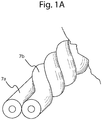
- the power and/or transmission line 7 comprises a pair of electrically conductive wires 7 a, 7 b twisted together to form substantially a twisted pair ( Figure 1, 1 A ), so as to disperse a substantial fraction of their electric field into the space outside the wires themselves, and thus increasing the changes in electrical capacity, in impedance and in time of flight due to the change of the "fringing field" due to the change in level of the liquid in which the line 7 is dipped, and consequently increasing the level measuring sensitivity.
- the twisted pair of wires twisted together does not behave like an antenna, making the measurements thereof much less polluted by external electromagnetic disturbances.
- the probing signal is a voltage signal with a rated or effective value advantageously equal to or greater than 0.1 volts (Vrms), more preferably equal to or greater than 1 volts (Vrms) and even more preferably equal to or less than 10 volt Vrms.
- the electrically conductive wires 7 a, 7 b are advantageously each enclosed in a respective insulating sheath, for example made of suitable polymeric material, so that the electrically conductive wires - or more generally the probing conductors- 7 a, 7 b are electrically insulated from one another as well as from the liquid in which they can be dipped to measure the level thereof.
- the insulating sheath that covers the wires 7 a, 7 b has a thickness preferably less than 1 millimetre, for example equal to or less than 0.5 millimetres, more preferably equal to or less than 0.1 millimetre.
- the insulating sheath can also be made as a paint or enamel that solidifies on the conductors of the wires 7 a, 7 b.
- such a twisted pair is bent substantially in a U or in any case so as to form a loop which forms the free end of the sensitive body 5 ( Figure 1 ) .
- such a loop - or more generally the sensitive body 5 - is arranged substantially vertical or at least so that it extends overall according to a top-bottom direction, even if not precisely vertical, so that it immerses to a greater or lesser extent in the liquid for which it is wished to measure the level.
- the phase shift undergone by the probing signal can be advantageously measured between a first PS and a second measuring point PA respectively upstream and downstream of the first measurement electrical load 11, for example immediately upstream and immediately downstream of the load 11.
- both the first PS and the second measuring point PA are both upstream of the section of the probing conductors 7 a, 7 b dipped in the liquid for which it is wished to measure the level ( Figure 1 ).
- the meter 1 can comprise two synchronous samplers, not shown and for example of the per se known type, and configured to measure in a mutually synchronised manner the voltages or currents in the measurement points PS and PA of the electric line upstream and downstream of the first measurement electrical load 11.
- the adoption of synchronous samplers too contributes to separating the effects, maximising the measurement sensitivity of the phase shift and of the time of flight, simplifying the circuits and the processing algorithms.
- the phase shift undergone by the probing signal can be advantageously measured between two measurement points PA, PB arranged upstream and downstream of the section of the power and/or transmission line 7 dipped in the liquid for which it is wished to measure the level.
- Such points can for example be the second PA and the third measuring point PB of the line 7.
- the meter 1 can comprise two corresponding synchronous samplers, not shown and for example of the per se known type, and configured to measure in a mutually synchronised manner the voltages or currents in the measurement points PA and PB of the power and/or transmission line 7 and more generally of the electrical circuits of the meter 1.
- both of the measurement points PA, PB can be outside of the bath of the liquid for which it is wished to measure the level; such a solution is constructively simple and particularly advantageous because it makes it possible to arrange both the signal generator 9 and the second measurement electrical load 13 outside of the liquid bath, at the limit also outside of the tank or other container S containing the liquid; the generator 9 and the load 13 can thus be subject to less stringent requirements of impermeability and flammability than if it operated constantly dipped in the fuel or other liquid to be measured.
- At least one among the second PA and third measuring point PB or both can be configured to operate constantly dipped in the liquid for which it is wished to measure the level.
- the measured phase shifts of the probing signal between two different measurement points are influenced by the length L 2 of the section of the twisted pair - and more generally of the section of the power and/or transmission line 7- dipped in the liquid to be measured.
- the logic unit 3 can be advantageously configured to calculate the change in electrical capacity associated with the fringing field based on the phase shifts measured in the first PS and in the second measuring point PA.
- the logic unit 3 can for example be configured for determining said electrical capacity, or in any case and more generally the aforementioned equivalent electrical capacity, determining, based on said phase shifts, one or more poles of the transfer function of at least part of the meter 1 and/or of the liquid in which the at least two probing conductors 7 a, 7 b are dipped.
- the logic unit 3 is programmed or in any case configured for determining such a capacity, determining the lowest frequency pole of such a transfer function, for example based on calculations and algorithms analogous to those that link the electrical capacity and the pole of a known RC filter.
- the logic unit 3 can be advantageously configured to calculate the time of flight of the probing signal in the section of the power and/or transmission line comprised between the second PA and the third measuring point PB, again based on the phase shift that the probing signal undergoes between the measurement points PA and PB, for example with per se mathematical processes and algorithms used for example in current laser telemeters.
- the logic unit 3 can be configured to calculate the time of flight between the measurement points PS and PA based on the phase shift between such points, and/or the pole of the transfer function and therefrom the equivalent electrical capacity based on the phase shift between the measurement points PA and PB, but generally with less sensitivity or greater complication of calculation with respect to the previous alternatives.
- the probing conductors 7 a, 7 b are coated with a material that is not very or not at all wettable, or their outer surface have been subjected to a suitable treatment that reduces or annulls the wettability, so as to prevent portions thereof from remaining wet even if out of the liquid, thus falsifying the measurement of the level.
- the electrical capacity depends linearly from the dielectric constant of the capacitor considered, whereas the time of flight depends on the square root of the dielectric constant of the medium considered; therefore the two determinations of the electrical capacity and of the time of flight are alternatives and independent from one another, one being able to be used to verify the other, correct possible errors or imprecisions of measurement or determine further parameters like for example the dielectric constant of the liquid for which it is wished to measure the level.
- the two measurements of the time of flight and of the pole or poles of the transfer function based on the phase shift of the probing signal can be carried out simultaneously or one after the other, a sufficiently short time after so as not to allow appreciable changes of the level of the liquid to be measured to occur.
- the two measurements of the time of flight and of the pole or poles of the transfer function based on the phase shift of the probing signal can be carried out with probing signals of different frequencies, for example with a probing signal at about 1 Megahertz for the first measurement and with a probing signal of about 10 megahertz for the second or vice-versa.
- the logic unit 3 or more generally the meter 1 is programmed or in any case configured to detect the phase shift of the signals acquired in the measurement points PS, PA, PB through suitable decimation or downsampling techniques.
- the logic unit 3 or more generally the meter 1 is programmed or in any case configured to detect the phase shift of the signals acquired in the measurement points PS, PA, PB for example through discrete Fourier transform and/or determining the phase and square component with a synchronous digital receiver, which carries out the multiplication of the sampled signal by two square signals (sine and cosine at the same frequency), to then evaluate the Fourier coefficients thereof.
- the logic unit 3 can be programmed or in any case configured to determine the phase shift between the voltages or currents detected in the measurement points PS, PA and/or PA, PB directly comparing signals having substantially the same frequency as the probing signal or in any case frequencies of the same order of magnitude, without frequency conversions, for example if the probing signal has relatively low frequencies, for example equal to or less than 10-20 Megahertz.
- the logic unit 3 or more generally the meter 1 can be provided with a frequency converter - for example a heterodyne converter - that transforms the signals measurement at the measurement points PS, PA, PB or others into lower frequency signals, making the phase shift with respect to the probing signal easier to measure.
- a frequency converter - for example a heterodyne converter - that transforms the signals measurement at the measurement points PS, PA, PB or others into lower frequency signals, making the phase shift with respect to the probing signal easier to measure.
- the frequency converter can be configured to reduce the signals measured at the measurement points PS, PA, PB or others into signals at a frequency equal to or less than 10 or 20 Megahertz.
- the frequency converter can comprise for example a mixer or sampler, for example of the per se known type.
- the logic unit 3 or more generally the meter 1 can be programmed or in any case configured to carry out a calibration procedure of the measurement of the level of the liquid through the time of flight along the power and/or transmission line 7.
- Such a calibration procedure can comprise for example the steps of detecting the time of flight along the line 7 when the sensitive body 5 is completely in air and when it is completely dipped in the liquid for which it is wished to measure the level.
- the measurement with sensitive body 5 completely dipped also provides a direct measurement of the properties of the liquid.
- the sensitive body 5 forms a prolongation that extends for a total length LCS preferably comprised between 0.1-10 metres, between 0.5-1 metre, between 0.2-0.5 metres or between 0.2-0.3 metres.
- the electrical path between the measurement points PS and PB, PA or PB, PS and PA can have a linear development the overall length of which is preferably comprised between 0.1-20 metres, between 0.1-20 metres, between 0.1-1 metres, between 0.1-0.6 metres, between 0.05-0.2 metres.
- the sensitive body 5 preferably has a substantially oblong shape.
- the meter 1 described earlier proved capable of measuring levels of liquid of a few decimetres with a resolution of the order of millimetres, using a probing signal of frequency 10 Megahertz in real time, i.e. without frequency conversions.
- measurers 1 capable of detecting the level of a liquid, such as a hydrocarbon-based fuel or water, with a resolution of one millimetre on a measurement range for example of 30-40 centimetres; such a measurement field is for example capable of covering the excursions of the level of the fuel in the tank of a helicopter.
- the logic unit 3 is programmed or in any case configured for detecting or in any case determining said phase shift based on at least 2000 voltage or current samples detected at the at least two predetermined measurement points PS, PA, PB.
- the logic unit 3 is configured to determine such a phase shift based on at least 4000 samples, more preferably based on at least 6000 samples and even more preferably based on at least 8000 samples.
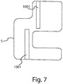
- the level of the liquid in which the sensitive body 5, 5', 5", 5 III , 5 IV is dipped is determined by measuring the phase shifts and the delays that the probing signal undergoes at different points of the power and/or transmission line 7 or other points of the electrical circuit, there are not in any way electrical charge in direct contact with the fuel or in any case with the liquid for which it is wished to measure the level; the meter 1 can therefore reach much greater intrinsic safety levels against fire with respect to known capacitive level measurers and can be used to measure the level also of non-electrically insulating liquids. Since a twisted pair or in any case electric cables can be used as sensitive body, a meter according to the invention can be installed more easily in tanks of irregular shape, like those shown for example in Figures 7 , 8 .
- Figure 7 schematically shows a tank of irregular shape in which two known capacitive level measurers 1001 are installed: such known capacitive measurers 1001, for constructive reasons and performance, must use a necessarily rectilinear cylindrical capacitor as sensitive body.
- a single known meter 1001 is not capable of describing curves, adapting to the irregular shape of tanks S like the one shown, and the level must be measured with two or more rectilinear capacitive measurers 1001 arranged vertically so as to form the required broken line.
- a single meter according to the invention is sufficient to detect the changes in level in tanks even of very irregular shape ( Figure 8 ).
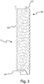
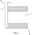
- the sensitive body 5, 5' can comprise not only a plurality of wires or electric cables twisted on themselves to form a twisted pair ( Figures 1, 1 A ) but electrical conductors also of different geometries, and comprise for example a wire or other electric conductor wound to form a helix 50' that forms a plurality of coils internally defining a cavity of substantially cylindrical or prismatic shape, and a rectilinear section 52' that from the most distal coil 54' rises inside such a cavity towards the proximal end 56' of the sensitive body 5' ( Figure 3 ).
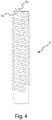
- the sensitive body 5" can comprise a wire or other electric cable bent in a U and wound on itself so as to form a double helix - as if it was a helix with two helices - internally defining a cavity for example of substantially cylindrical or prismatic shape ( Figure 4 ).
- the sensitive body can comprise a bundle comprising a plurality of wires or other cables or electrical conductors arranged side-by-side and wound on themselves to form a multiple helix internally defining a cavity for example of substantially cylindrical or prismatic shape.
- the sensitive body 5 III , 5 IV can comprise one or more wires, cables or other electrical conductors that form one or more coil sections, and possibly a rectilinear - or in any case less twisted - rising section that connects the distal ends 54 III , 54 IV and proximal ends 56 III , 56 IV of the sensitive body itself.
- the one or more coil sections can form one or more loops that extend substantially in a direction parallel or longitudinal to the free surface of the liquid for which it is wished to measure the level, where the free surface of the liquid is considered in conditions of normal operation or in suitable standard conditions.
- Such sensitive bodies 5 III , 5 IV can have a substantially planar overall shape or form one or more tubular sections, for example formed from a respective coil section that encloses a substantially cylindrical or prismatic cavity.
- the coil shape makes it possible to increase the sensitivity and the resolution of the measurements in particular sections and level ranges, or to make measurers that detect changes in level only for relatively rough and greatly discretized ranges, for example only distinguishing between a too full level, a too empty level and an intermediate level between them.
- the materials used, as well as the sizes, can be whatever according to the technical requirements.
- references to a "first, second, third, ... n-th entity" have the only purpose of distinguishing them from one another but the indication of the n-th entity does not necessarily imply the existence of the first, second ... (n- 1 )th entity.
Landscapes
- Physics & Mathematics (AREA)
- Engineering & Computer Science (AREA)
- Fluid Mechanics (AREA)
- General Physics & Mathematics (AREA)
- Power Engineering (AREA)
- Signal Processing (AREA)
- Electromagnetism (AREA)
- Thermal Sciences (AREA)
- Measurement Of Levels Of Liquids Or Fluent Solid Materials (AREA)
- Level Indicators Using A Float (AREA)
Applications Claiming Priority (1)
| Application Number | Priority Date | Filing Date | Title |
|---|---|---|---|
| IT102019000014043A IT201900014043A1 (it) | 2019-08-05 | 2019-08-05 | Misuratore e procedimento per misurare il livello di un liquido. |
Publications (3)
| Publication Number | Publication Date |
|---|---|
| EP3772636A1 true EP3772636A1 (fr) | 2021-02-10 |
| EP3772636C0 EP3772636C0 (fr) | 2025-06-25 |
| EP3772636B1 EP3772636B1 (fr) | 2025-06-25 |
Family
ID=69173140
Family Applications (1)
| Application Number | Title | Priority Date | Filing Date |
|---|---|---|---|
| EP20189345.0A Active EP3772636B1 (fr) | 2019-08-05 | 2020-08-04 | Compteur et procédé de mesure du niveau d'un liquide |
Country Status (5)
| Country | Link |
|---|---|
| US (1) | US20210041282A1 (fr) |
| EP (1) | EP3772636B1 (fr) |
| ES (1) | ES3037192T3 (fr) |
| IT (1) | IT201900014043A1 (fr) |
| PL (1) | PL3772636T3 (fr) |
Cited By (1)
| Publication number | Priority date | Publication date | Assignee | Title |
|---|---|---|---|---|
| DK202330396A1 (en) * | 2023-12-13 | 2025-07-01 | Typhon Tech Aps | Capacitive sensor |
Citations (2)
| Publication number | Priority date | Publication date | Assignee | Title |
|---|---|---|---|---|
| US20070101811A1 (en) * | 2005-11-04 | 2007-05-10 | David S. Nyce | Distributed impedance sensor |
| US20130298667A1 (en) * | 2011-01-26 | 2013-11-14 | Gerd Bechtel | Apparatus and Method for Capacitive Fill Level Measurement |
-
2019
- 2019-08-05 IT IT102019000014043A patent/IT201900014043A1/it unknown
-
2020
- 2020-08-04 ES ES20189345T patent/ES3037192T3/es active Active
- 2020-08-04 PL PL20189345.0T patent/PL3772636T3/pl unknown
- 2020-08-04 EP EP20189345.0A patent/EP3772636B1/fr active Active
- 2020-08-07 US US16/988,063 patent/US20210041282A1/en not_active Abandoned
Patent Citations (2)
| Publication number | Priority date | Publication date | Assignee | Title |
|---|---|---|---|---|
| US20070101811A1 (en) * | 2005-11-04 | 2007-05-10 | David S. Nyce | Distributed impedance sensor |
| US20130298667A1 (en) * | 2011-01-26 | 2013-11-14 | Gerd Bechtel | Apparatus and Method for Capacitive Fill Level Measurement |
Cited By (1)
| Publication number | Priority date | Publication date | Assignee | Title |
|---|---|---|---|---|
| DK202330396A1 (en) * | 2023-12-13 | 2025-07-01 | Typhon Tech Aps | Capacitive sensor |
Also Published As
| Publication number | Publication date |
|---|---|
| EP3772636C0 (fr) | 2025-06-25 |
| IT201900014043A1 (it) | 2021-02-05 |
| PL3772636T3 (pl) | 2025-09-22 |
| ES3037192T3 (en) | 2025-09-30 |
| EP3772636B1 (fr) | 2025-06-25 |
| US20210041282A1 (en) | 2021-02-11 |
Similar Documents
| Publication | Publication Date | Title |
|---|---|---|
| KR101285460B1 (ko) | 용량성 액체 레벨 센서 | |
| EP2414792B1 (fr) | Système de jaugeage de carburant utilisant une sonde numérique de jaugeage | |
| US3862571A (en) | Multielectrode capacitive liquid level sensing system | |
| US5051921A (en) | Method and apparatus for detecting liquid composition and actual liquid level | |
| US7010985B2 (en) | Gauge for measuring fuel level in a tank, and a system for measuring the weight of fuel in the tank | |
| US3901079A (en) | Two-mode capacitive liquid level sensing system | |
| US7129693B2 (en) | Modular voltage sensor | |
| US8196465B2 (en) | Apparatus for ascertaining and monitoring fill level of a medium in a container | |
| US7123032B2 (en) | Voltage sensor and dielectric material | |
| CN100439880C (zh) | 用于电容式料位测量的测量仪表的制造侧标定以及相应的测量仪表 | |
| EP3772636B1 (fr) | Compteur et procédé de mesure du niveau d'un liquide | |
| WO2010077893A1 (fr) | Capteur de niveau de liquide avec capacitance de référence | |
| US12270695B2 (en) | Capacitive fuel gaging system with resistive elements | |
| CA2672794C (fr) | Dispositif pour determiner et/ou surveiller une grandeur de traitement | |
| EP3415929B1 (fr) | Accessoire électrique comprenant un élément de détection de tension sur un câble | |
| US8434211B2 (en) | Method for manufacturing a capacitive measuring apparatus | |
| RU240591U1 (ru) | Высоковольтный измерительный преобразователь напряжения | |
| RU111680U1 (ru) | Устройство для измерения напряжения на высоковольтных линиях электропередач | |
| CN109374982A (zh) | 一种液体介电常数测量装置 | |
| RU210982U1 (ru) | Высоковольтный измерительный преобразователь напряжения | |
| US20250182926A1 (en) | Connection conductor, arrangement having a connection conductor and use of a connection conductor | |
| RU85641U1 (ru) | Емкостной измеритель уровня жидкости | |
| GB2549482A (en) | Charge measurement apparatus and method | |
| JP7071733B2 (ja) | センサ | |
| SU737843A1 (ru) | Устройство дл измерени электрической емкости кабельных жил и проводов |
Legal Events
| Date | Code | Title | Description |
|---|---|---|---|
| PUAI | Public reference made under article 153(3) epc to a published international application that has entered the european phase |
Free format text: ORIGINAL CODE: 0009012 |
|
| STAA | Information on the status of an ep patent application or granted ep patent |
Free format text: STATUS: THE APPLICATION HAS BEEN PUBLISHED |
|
| AK | Designated contracting states |
Kind code of ref document: A1 Designated state(s): AL AT BE BG CH CY CZ DE DK EE ES FI FR GB GR HR HU IE IS IT LI LT LU LV MC MK MT NL NO PL PT RO RS SE SI SK SM TR |
|
| AX | Request for extension of the european patent |
Extension state: BA ME |
|
| STAA | Information on the status of an ep patent application or granted ep patent |
Free format text: STATUS: REQUEST FOR EXAMINATION WAS MADE |
|
| 17P | Request for examination filed |
Effective date: 20210802 |
|
| RBV | Designated contracting states (corrected) |
Designated state(s): AL AT BE BG CH CY CZ DE DK EE ES FI FR GB GR HR HU IE IS IT LI LT LU LV MC MK MT NL NO PL PT RO RS SE SI SK SM TR |
|
| STAA | Information on the status of an ep patent application or granted ep patent |
Free format text: STATUS: EXAMINATION IS IN PROGRESS |
|
| 17Q | First examination report despatched |
Effective date: 20230220 |
|
| GRAP | Despatch of communication of intention to grant a patent |
Free format text: ORIGINAL CODE: EPIDOSNIGR1 |
|
| STAA | Information on the status of an ep patent application or granted ep patent |
Free format text: STATUS: GRANT OF PATENT IS INTENDED |
|
| RIC1 | Information provided on ipc code assigned before grant |
Ipc: G01F 25/00 20060101ALN20250127BHEP Ipc: G01F 23/80 20220101ALI20250127BHEP Ipc: G01F 23/263 20220101ALI20250127BHEP Ipc: G01F 23/26 20060101ALI20250127BHEP Ipc: G01F 23/00 20060101AFI20250127BHEP |
|
| INTG | Intention to grant announced |
Effective date: 20250207 |
|
| GRAS | Grant fee paid |
Free format text: ORIGINAL CODE: EPIDOSNIGR3 |
|
| RAP1 | Party data changed (applicant data changed or rights of an application transferred) |
Owner name: LOGIC S.P.A. |
|
| GRAA | (expected) grant |
Free format text: ORIGINAL CODE: 0009210 |
|
| STAA | Information on the status of an ep patent application or granted ep patent |
Free format text: STATUS: THE PATENT HAS BEEN GRANTED |
|
| AK | Designated contracting states |
Kind code of ref document: B1 Designated state(s): AL AT BE BG CH CY CZ DE DK EE ES FI FR GB GR HR HU IE IS IT LI LT LU LV MC MK MT NL NO PL PT RO RS SE SI SK SM TR |
|
| REG | Reference to a national code |
Ref country code: GB Ref legal event code: FG4D |
|
| REG | Reference to a national code |
Ref country code: CH Ref legal event code: EP |
|
| REG | Reference to a national code |
Ref country code: CH Ref legal event code: EP |
|
| REG | Reference to a national code |
Ref country code: IE Ref legal event code: FG4D |
|
| REG | Reference to a national code |
Ref country code: DE Ref legal event code: R096 Ref document number: 602020053195 Country of ref document: DE |
|
| U01 | Request for unitary effect filed |
Effective date: 20250703 |
|
| U07 | Unitary effect registered |
Designated state(s): AT BE BG DE DK EE FI FR IT LT LU LV MT NL PT RO SE SI Effective date: 20250710 |
|
| U20 | Renewal fee for the european patent with unitary effect paid |
Year of fee payment: 6 Effective date: 20250814 |
|
| REG | Reference to a national code |
Ref country code: ES Ref legal event code: FG2A Ref document number: 3037192 Country of ref document: ES Kind code of ref document: T3 Effective date: 20250930 |
|
| PGFP | Annual fee paid to national office [announced via postgrant information from national office to epo] |
Ref country code: ES Payment date: 20250905 Year of fee payment: 6 |
|
| PG25 | Lapsed in a contracting state [announced via postgrant information from national office to epo] |
Ref country code: GR Free format text: LAPSE BECAUSE OF FAILURE TO SUBMIT A TRANSLATION OF THE DESCRIPTION OR TO PAY THE FEE WITHIN THE PRESCRIBED TIME-LIMIT Effective date: 20250926 Ref country code: NO Free format text: LAPSE BECAUSE OF FAILURE TO SUBMIT A TRANSLATION OF THE DESCRIPTION OR TO PAY THE FEE WITHIN THE PRESCRIBED TIME-LIMIT Effective date: 20250925 |
|
| PGFP | Annual fee paid to national office [announced via postgrant information from national office to epo] |
Ref country code: TR Payment date: 20250730 Year of fee payment: 6 Ref country code: PL Payment date: 20250731 Year of fee payment: 6 |
|
| PGFP | Annual fee paid to national office [announced via postgrant information from national office to epo] |
Ref country code: GB Payment date: 20250731 Year of fee payment: 6 |
|
| PG25 | Lapsed in a contracting state [announced via postgrant information from national office to epo] |
Ref country code: HR Free format text: LAPSE BECAUSE OF FAILURE TO SUBMIT A TRANSLATION OF THE DESCRIPTION OR TO PAY THE FEE WITHIN THE PRESCRIBED TIME-LIMIT Effective date: 20250625 |
|
| PG25 | Lapsed in a contracting state [announced via postgrant information from national office to epo] |
Ref country code: RS Free format text: LAPSE BECAUSE OF FAILURE TO SUBMIT A TRANSLATION OF THE DESCRIPTION OR TO PAY THE FEE WITHIN THE PRESCRIBED TIME-LIMIT Effective date: 20250925 |
|
| PGFP | Annual fee paid to national office [announced via postgrant information from national office to epo] |
Ref country code: CZ Payment date: 20250818 Year of fee payment: 6 |
|
| PG25 | Lapsed in a contracting state [announced via postgrant information from national office to epo] |
Ref country code: IS Free format text: LAPSE BECAUSE OF FAILURE TO SUBMIT A TRANSLATION OF THE DESCRIPTION OR TO PAY THE FEE WITHIN THE PRESCRIBED TIME-LIMIT Effective date: 20251025 |
|
| PG25 | Lapsed in a contracting state [announced via postgrant information from national office to epo] |
Ref country code: SM Free format text: LAPSE BECAUSE OF FAILURE TO SUBMIT A TRANSLATION OF THE DESCRIPTION OR TO PAY THE FEE WITHIN THE PRESCRIBED TIME-LIMIT Effective date: 20250625 |
|
| PG25 | Lapsed in a contracting state [announced via postgrant information from national office to epo] |
Ref country code: SK Free format text: LAPSE BECAUSE OF FAILURE TO SUBMIT A TRANSLATION OF THE DESCRIPTION OR TO PAY THE FEE WITHIN THE PRESCRIBED TIME-LIMIT Effective date: 20250625 |
|
| REG | Reference to a national code |
Ref country code: CH Ref legal event code: H13 Free format text: ST27 STATUS EVENT CODE: U-0-0-H10-H13 (AS PROVIDED BY THE NATIONAL OFFICE) Effective date: 20260324 |
|
| PG25 | Lapsed in a contracting state [announced via postgrant information from national office to epo] |
Ref country code: MC Free format text: LAPSE BECAUSE OF FAILURE TO SUBMIT A TRANSLATION OF THE DESCRIPTION OR TO PAY THE FEE WITHIN THE PRESCRIBED TIME-LIMIT Effective date: 20250625 |
|
| PG25 | Lapsed in a contracting state [announced via postgrant information from national office to epo] |
Ref country code: CH Free format text: LAPSE BECAUSE OF NON-PAYMENT OF DUE FEES Effective date: 20250831 |
|
| PLBE | No opposition filed within time limit |
Free format text: ORIGINAL CODE: 0009261 |
|
| STAA | Information on the status of an ep patent application or granted ep patent |
Free format text: STATUS: NO OPPOSITION FILED WITHIN TIME LIMIT |