EP3772615B1 - Sequential combustor assembly for a gas turbine assembly and method for operating said sequential combustor assembly - Google Patents
Sequential combustor assembly for a gas turbine assembly and method for operating said sequential combustor assembly Download PDFInfo
- Publication number
- EP3772615B1 EP3772615B1 EP19190692.4A EP19190692A EP3772615B1 EP 3772615 B1 EP3772615 B1 EP 3772615B1 EP 19190692 A EP19190692 A EP 19190692A EP 3772615 B1 EP3772615 B1 EP 3772615B1
- Authority
- EP
- European Patent Office
- Prior art keywords
- combustor
- flow rate
- line
- air flow
- fuel
- Prior art date
- Legal status (The legal status is an assumption and is not a legal conclusion. Google has not performed a legal analysis and makes no representation as to the accuracy of the status listed.)
- Active
Links
Images
Classifications
-
- F—MECHANICAL ENGINEERING; LIGHTING; HEATING; WEAPONS; BLASTING
- F23—COMBUSTION APPARATUS; COMBUSTION PROCESSES
- F23R—GENERATING COMBUSTION PRODUCTS OF HIGH PRESSURE OR HIGH VELOCITY, e.g. GAS-TURBINE COMBUSTION CHAMBERS
- F23R3/00—Continuous combustion chambers using liquid or gaseous fuel
- F23R3/02—Continuous combustion chambers using liquid or gaseous fuel characterised by the air-flow or gas-flow configuration
- F23R3/26—Controlling the air flow
-
- F—MECHANICAL ENGINEERING; LIGHTING; HEATING; WEAPONS; BLASTING
- F02—COMBUSTION ENGINES; HOT-GAS OR COMBUSTION-PRODUCT ENGINE PLANTS
- F02C—GAS-TURBINE PLANTS; AIR INTAKES FOR JET-PROPULSION PLANTS; CONTROLLING FUEL SUPPLY IN AIR-BREATHING JET-PROPULSION PLANTS
- F02C9/00—Controlling gas-turbine plants; Controlling fuel supply in air- breathing jet-propulsion plants
- F02C9/16—Control of working fluid flow
- F02C9/18—Control of working fluid flow by bleeding, bypassing or acting on variable working fluid interconnections between turbines or compressors or their stages
-
- F—MECHANICAL ENGINEERING; LIGHTING; HEATING; WEAPONS; BLASTING
- F23—COMBUSTION APPARATUS; COMBUSTION PROCESSES
- F23R—GENERATING COMBUSTION PRODUCTS OF HIGH PRESSURE OR HIGH VELOCITY, e.g. GAS-TURBINE COMBUSTION CHAMBERS
- F23R3/00—Continuous combustion chambers using liquid or gaseous fuel
- F23R3/28—Continuous combustion chambers using liquid or gaseous fuel characterised by the fuel supply
- F23R3/286—Continuous combustion chambers using liquid or gaseous fuel characterised by the fuel supply having fuel-air premixing devices
-
- F—MECHANICAL ENGINEERING; LIGHTING; HEATING; WEAPONS; BLASTING
- F23—COMBUSTION APPARATUS; COMBUSTION PROCESSES
- F23R—GENERATING COMBUSTION PRODUCTS OF HIGH PRESSURE OR HIGH VELOCITY, e.g. GAS-TURBINE COMBUSTION CHAMBERS
- F23R3/00—Continuous combustion chambers using liquid or gaseous fuel
- F23R3/28—Continuous combustion chambers using liquid or gaseous fuel characterised by the fuel supply
- F23R3/34—Feeding into different combustion zones
- F23R3/346—Feeding into different combustion zones for staged combustion
-
- F—MECHANICAL ENGINEERING; LIGHTING; HEATING; WEAPONS; BLASTING
- F23—COMBUSTION APPARATUS; COMBUSTION PROCESSES
- F23R—GENERATING COMBUSTION PRODUCTS OF HIGH PRESSURE OR HIGH VELOCITY, e.g. GAS-TURBINE COMBUSTION CHAMBERS
- F23R2900/00—Special features of, or arrangements for continuous combustion chambers; Combustion processes therefor
- F23R2900/00002—Gas turbine combustors adapted for fuels having low heating value [LHV]
-
- F—MECHANICAL ENGINEERING; LIGHTING; HEATING; WEAPONS; BLASTING
- F23—COMBUSTION APPARATUS; COMBUSTION PROCESSES
- F23R—GENERATING COMBUSTION PRODUCTS OF HIGH PRESSURE OR HIGH VELOCITY, e.g. GAS-TURBINE COMBUSTION CHAMBERS
- F23R2900/00—Special features of, or arrangements for continuous combustion chambers; Combustion processes therefor
- F23R2900/03341—Sequential combustion chambers or burners
Definitions
- the present invention relates to a sequential combustor assembly for a gas turbine assembly and to a method for operating said sequential combustor assembly.
- the method for operating a sequential combustor for a gas turbine according to the invention is particularly useful when the above sequential combustor assembly is fed with a high reactive fuel, for instance a fuel comprising hydrogen.
- a gas turbine assembly for a power plant for the production of electrical energy comprises a compressor, a combustor assembly and at least one turbine.
- the compressor is supplied with air and comprises a plurality of blades compressing the supplied air.
- the compressed air leaving the compressor flows into a plenum, i.e. a closed volume delimited by an outer casing, and from there into the combustor assembly.
- a plenum i.e. a closed volume delimited by an outer casing
- the compressed air and at least one fuel are combusted.
- the resulting hot gas leaves the combustor assembly and is expanded in the turbine performing work.
- sequential combustor assemblies can be used.
- a sequential combustor assembly comprises two combustors in series: a first-stage combustor and a second-stage combustor, which is arranged downstream the first-stage combustor along the gas flow and is fed with the hot gas leaving the first-stage combustor.
- annular type Two different kinds of sequential combustor assemblies are mainly known: annular type and can type.
- the first-stage combustor and the second-stage combustor are annular shaped and are physically separated by a stage of turbine blades, called high-pressure turbine.
- the combustor assembly comprises a plurality of can-shaped casings, each of which comprises a first-stage combustor and a second-stage combustor arranged one downstream the other inside the common can-shaped casing.
- a mixer is arranged between the first-stage combustor and the second-stage combustor.
- the first-stage combustor and the second-stage combustor are supplied with fuel.
- one of the most important challenges is to use high reactive fuels, e.g. with high amounts of hydrogen (H 2 ) or higher hydrocarbons (e.g. ethane, propane).
- high reactive fuels e.g. with high amounts of hydrogen (H 2 ) or higher hydrocarbons (e.g. ethane, propane).
- composition of natural gas considered for use within gas turbines is becoming significantly more variable due to increased use of liquefied natural gas and a wider range of gas sources and extraction methods.
- a change in fuel reactivity implies a change in flame location.
- higher fuel reactivity like hydrogen based fuels
- forces the flame to move upstream increasing NOx emissions, and potentially overheating the burners
- lower fuel reactivity results in the opposite and pushes the flame downstream, increasing CO and unburned hydrocarbons emissions due to the insufficient burnout time.
- the position of the flame in the second-stage combustor can be controlled by the temperature at the inlet of the second-stage combustor (self/spontaneous ignition). By lowering/increasing the inlet temperature it is therefore possible to move the flame downstream/upstream.
- the change of the first stage flame temperature and/or the second stage inlet temperature could be limited.
- a sequential combustor assembly comprising:
- the fuel fed to the combustor assembly can be changed significantly broadening the operation window and further extending the fuel reactivity acceptable range.
- the combustor assembly comprises a control device configured to set a desired ratio between the first air flow rate and the second air flow rate on the basis of the kind of first fuel and second fuel and on the basis of the operating conditions of the sequential combustor assembly.
- the fuel composition can be changed without any risks as the control device is able to adjust the ratio even in real time.
- control device is configured to set a desired ratio between the first air flow rate and the second air flow rate so as to obtain a desired temperature of the gas at the inlet of the second-stage combustor.
- the second line supplies air into a mixer arranged between the first-stage combustor and the second-stage combustor.
- the second line supplies air into a high pressure turbine arranged between the first-stage combustor and the second-stage combustor.
- the adjusting device comprises a first regulating valve on the first line.
- the adjusting device comprises a second regulating valve on the second line.
- the adjusting device comprises a three-way valve configured to adjust the first air flow rate in the first line and the second air flow rate in the second line.
- the adjusting device comprises a by-pass line and a by-pass valve on the by-pass line; the by-pass line being arranged in parallel to the first line and/or to the second line.
- a sequential combustor assembly for a gas turbine assembly comprising:
- the method comprises setting a desired ratio between the first air flow rate and the second air flow rate on the basis of the kind of first fuel and second fuel and on the basis of the operating conditions of the sequential combustor assembly.
- the setting is made to obtain a desired temperature of the gas at the inlet of the second-stage combustor.
- the first fuel and the second fuel are highly reactive fuels.
- the first fuel and the second fuel are low reactive fuels.
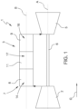
- reference numeral 1 indicates a gas turbine assembly.
- the gas turbine assembly 1 comprises a compressor 2, a sequential combustor assembly 3 and a turbine 5.
- the compressor 2 and the turbine 5 extend along a main axis A.
- an airflow compressed in the compressor 2 is mixed with fuel and is burned in the sequential combustor assembly 3.
- the burned mixture is then expanded in the turbine 5 and converted in mechanical power by a shaft 6, which is connected to an alternator (not shown).
- the sequential combustor assembly 3 is of the can-type and comprises a plurality of cans 7(only one being represented in figure 1 ).
- Each can 7 extends along a main axis B and comprises a first-stage combustor 8 and a second-stage combustor 9 sequentially arranged along the gas flow direction G.
- the second-stage combustor 9 is arranged downstream the first-stage combustor 8 along the gas flow direction G.
- a mixer 11 is arranged between the first stage combustor 8 and the second stage combustor 9 .
- the first stage combustor 8 defines a first combustion chamber 14, the second stage combustor 9 defines a second combustion chamber 16, while the mixer 11 defines a mixing chamber 17.
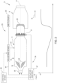
- the first combustion chamber 14, the second combustion chamber 16 and the mixing chamber 17 are in fluid-communication and are defined by a liner 18 (see figure 2 ) which extends along the longitudinal axis B.
- the first-stage combustor 8 comprises at least one first burner 20 and the second-stage combustor 9 comprises at least one second burner 21.
- the first stage combustor 8 comprises a plurality of first burners 20 (schematically represented by a box) and the second stage combustor comprises a plurality of second burners 21 (schematically represented by a box).
- first burners 20 In use the first burners 20 generate a first flame represented schematically by areas having reference 22 and the second burners 21 generate a second flame represented schematically by areas having reference 23.
- the sequential combustor assembly 3 also comprises a fuel supply circuit 24 and an air supply circuit 25 and a control device 26.
- the fuel supply circuit 24 is configured to supply at least one first fuel to the first burners 20 and at least one second fuel to the second burners 21 and comprises an actuator assembly 27 (schematically represented) configured to regulate the amount of fuel supplied to the first burners 20 and to the second burners 21 under the control of the control device 26.
- the first fuel and the second fuel are identical.
- the air supply circuit 25 is connected to an air plenum 28 (schematically represented in figure 2 ) and comprises a first line 30 configured to supply air to the at least one first burner 20 of the first stage combustor 8, a second line 31 configured to supply air downstream the at least one first flame 22 and upstream the second stage combustor 9 and an adjusting device 33 configured to adjust a first air flow rate in the first line 30 and a second air flow rate in the second line 31 under the control of the control device 26.
- an air plenum 28 (schematically represented in figure 2 ) and comprises a first line 30 configured to supply air to the at least one first burner 20 of the first stage combustor 8, a second line 31 configured to supply air downstream the at least one first flame 22 and upstream the second stage combustor 9 and an adjusting device 33 configured to adjust a first air flow rate in the first line 30 and a second air flow rate in the second line 31 under the control of the control device 26.
- the second line 31 is configured to supply air to the mixer 11.
- the second line 31 supplies air to a high pressure turbine arranged upstream the second stage combustor 9.
- control device 26 regulates the adjusting device 33 to control the air ratio between the first air flow rate and the second air flow rate.
- the air ratio is controlled so as the hot gas at the inlet of the second stage combustor 9 has a desired temperature.
- control device 26 sets a desired air ratio so as to obtain a desired temperature of the gas at the inlet of the second-stage combustor 9 and the adjusting device 33 adjusts the first air flow rate and the second air flow rate so as to obtain the desired air ratio.
- the control device 26 is configured to set the desired ratio between the first air flow rate and the second air flow rate on the basis of the kind of fuel used in the first burners 20 and in the second burners 21 and on the basis of the operating conditions of the sequential combustor assembly 3.
- the fuel supplied to the first burners 20 and to the second burners 21 is a highly-reactive fuel (for example a hydrogen based fuel).
- a highly-reactive fuel for example a hydrogen based fuel.
- the temperature at the inlet of the second stage combustor 9 should be as low as possible in order to move the second flame 23 downstream and avoid a flame flashbacks in the second burners 21.
- the temperature at the inlet of the second stage combustor 9 should be regulated so as to move the second flame 23 upstream, avoiding an increase of CO and unburned hydrocarbons emissions.
- control device 26 is configured to define, for each fuel type, a desired air ratio between the first air flow rate and the second air flow rate so as to obtain the proper temperature at the inlet of the second burner 26.
- the adjusting device 33 regulates the first air flow rate and the second air flow rate.
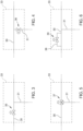
- FIG 3 a first embodiment of the adjusting device 33 is represented.
- the adjusting device 33 comprises a first regulating valve 35 arranged along the first line 30.
- the first regulating valve 35 is controlled by the control device 26.
- the amount of air coming from the air plenum 28 depends on the operating conditions of the turbine assembly 1 and is known. Therefore adjusting the first regulating valve 35 implies a regulation of the air flow rate also in the second line 31.
- a restriction can be arranged along the second line 31 to set a desired flow rate in the second line 31.
- the adjusting device 33 comprises a second regulating valve 36 arranged along the second line 30.
- the second regulating valve 36 is controlled by the control device 26.
- the amount of air coming from the air plenum 28 depends on the operating conditions of the turbine assembly 1 and is known. Therefore adjusting the second regulating valve 36 implies a regulation of the air flow rate also in the first line 30.
- a restriction can be arranged along the first line 30 to set a desired flow rate in the first line 30.
- the adjusting device 33 comprises a three-way valve 37 arranged at the connection between the first line 30 and the second line 31.
- the three-way valve 37 is controlled by the control device 26 and regulates the first air flow rate in the first line 30 and the second air flow rate in the second line 31.
- the adjusting device 33 comprises a by-pass line 38 and a by-pass valve 39 arranged along the by-pass line 38.
- the by-pass line 38 is arranged in parallel to the first line 30.
- the by-pass valve 39 is controlled by the control device 26.
- the amount of air coming from the air plenum 28 depends on the operating conditions of the turbine assembly 1 and is known. Therefore adjusting the by-pass valve 39 implies a regulation of the air flow rate also in the first line 30 and in the second line 31.
- Such an embodiment is particularly suitable for applications on already existing gas turbine assemblies.
- the addition of a by-pass line in fact, minimizes the structural changes to the already existing combustor assembly.
- the by-pass line 38 is arranged in parallel to the second line 31.
- a restriction can be arranged along the first line 30 and/or along the second line 31 to set a desired flow rate in the first line 30 and/or in the second line 31.
Landscapes
- Engineering & Computer Science (AREA)
- Chemical & Material Sciences (AREA)
- Combustion & Propulsion (AREA)
- Mechanical Engineering (AREA)
- General Engineering & Computer Science (AREA)
- Physics & Mathematics (AREA)
- Fluid Mechanics (AREA)
Description
- The present invention relates to a sequential combustor assembly for a gas turbine assembly and to a method for operating said sequential combustor assembly.
- The method for operating a sequential combustor for a gas turbine according to the invention is particularly useful when the above sequential combustor assembly is fed with a high reactive fuel, for instance a fuel comprising hydrogen.
- As known, a gas turbine assembly for a power plant for the production of electrical energy comprises a compressor, a combustor assembly and at least one turbine.
- In particular, the compressor is supplied with air and comprises a plurality of blades compressing the supplied air. The compressed air leaving the compressor flows into a plenum, i.e. a closed volume delimited by an outer casing, and from there into the combustor assembly. In the combustor assembly the compressed air and at least one fuel are combusted.
- The resulting hot gas leaves the combustor assembly and is expanded in the turbine performing work.
- In order to achieve a high efficiency, high temperatures are required during combustion. However, due to these high temperatures, high NOx emissions are generated.
- In order to reduce these emissions and to increase operational flexibility, sequential combustor assemblies can be used.
- In general, a sequential combustor assembly comprises two combustors in series: a first-stage combustor and a second-stage combustor, which is arranged downstream the first-stage combustor along the gas flow and is fed with the hot gas leaving the first-stage combustor.
- Two different kinds of sequential combustor assemblies are mainly known: annular type and can type.
- In the annular combustor assemblies, the first-stage combustor and the second-stage combustor are annular shaped and are physically separated by a stage of turbine blades, called high-pressure turbine.
- In the can type, the combustor assembly comprises a plurality of can-shaped casings, each of which comprises a first-stage combustor and a second-stage combustor arranged one downstream the other inside the common can-shaped casing. Preferably, a mixer is arranged between the first-stage combustor and the second-stage combustor.
- In both embodiments, the first-stage combustor and the second-stage combustor are supplied with fuel.
- Starting from the above mentioned structures of sequential gas turbines, today the need of improving the fuel flexibility is present. However, the change of the kind of fuel should be made considering that emissions should be kept under the limits and that the power plant should maintain high performance.
- In particular, one of the most important challenges is to use high reactive fuels, e.g. with high amounts of hydrogen (H2) or higher hydrocarbons (e.g. ethane, propane).
- At the same time, the composition of natural gas considered for use within gas turbines is becoming significantly more variable due to increased use of liquefied natural gas and a wider range of gas sources and extraction methods.
- Moreover, also fuels having very low calorific values and coming from waste processes or biomass gasification are increasingly of interest.
- Fuel flexibility is therefore of utmost importance in modern gas turbine development.
- A change in fuel reactivity implies a change in flame location. In particular, higher fuel reactivity (like hydrogen based fuels) forces the flame to move upstream, increasing NOx emissions, and potentially overheating the burners, while lower fuel reactivity results in the opposite and pushes the flame downstream, increasing CO and unburned hydrocarbons emissions due to the insufficient burnout time.
- Consequently, when burning highly reactive fuels (e.g. fuels containing large quantities of either higher hydrocarbons or hydrogen) the flame moves upstream compared to the case of natural gas, thus increasing the risk of flashback. While when burning low reactive fuels the flame moves downstream, increasing CO and unburned hydrocarbons emissions.
- The position of the flame in the second-stage combustor can be controlled by the temperature at the inlet of the second-stage combustor (self/spontaneous ignition). By lowering/increasing the inlet temperature it is therefore possible to move the flame downstream/upstream.
- With a fixed air distribution, the change of the first stage flame temperature and/or the second stage inlet temperature could be limited.
- In such case fuels with particularly high or low reactivity could not be used, because of a too narrow operating window either because of emissions or burner local temperatures.
- A sequential combustor assembly and its method of operation are described by
US2015/101341 . - It is therefore an object of the present invention to provide a sequential combustor assembly, which enables avoiding or at least mitigating the described drawbacks.
- In particular, it is an object of the present invention to provide a sequential combustor assembly configured to allow a reliable control of the temperature at the inlet of the second stage combustor.
- According to the present invention, there is provided a sequential combustor assembly comprising:
- a first-stage combustor comprising at least one first burner fed with at least one first fuel and configured to generate, in use, at least one first flame;
- a second-stage combustor arranged downstream the first-stage combustor and fed by the hot gas leaving the first-stage combustor; the second-stage combustor comprising at least one second burner fed with at least one second fuel and being configured to generate, in use, a second flame;
- an air supply circuit comprising:
- a first line configured to supply air to the at least one first burner of the first-stage combustor;
- a second line configured to supply air downstream the at least one first flame and upstream the second-stage combustor;
- an adjusting device configured to adjust a first air flow rate in the first line and a second air flow rate in the second line so as to control the ratio between the first air flow rate and the second air flow rate.
- In this way the fuel fed to the combustor assembly can be changed significantly broadening the operation window and further extending the fuel reactivity acceptable range.
- According to the present invention, the combustor assembly comprises a control device configured to set a desired ratio between the first air flow rate and the second air flow rate on the basis of the kind of first fuel and second fuel and on the basis of the operating conditions of the sequential combustor assembly.
- In this way, the fuel composition can be changed without any risks as the control device is able to adjust the ratio even in real time.
- According to the present invention, the control device is configured to set a desired ratio between the first air flow rate and the second air flow rate so as to obtain a desired temperature of the gas at the inlet of the second-stage combustor.
- In this way the flame position in the second-stage combustor is reliably controlled.
- According to an embodiment of the present invention, the second line supplies air into a mixer arranged between the first-stage combustor and the second-stage combustor.
- According to an embodiment of the present invention, the second line supplies air into a high pressure turbine arranged between the first-stage combustor and the second-stage combustor.
- According to an embodiment of the present invention, the adjusting device comprises a first regulating valve on the first line.
- According to an embodiment of the present invention, the adjusting device comprises a second regulating valve on the second line.
- According to an embodiment of the present invention, the adjusting device comprises a three-way valve configured to adjust the first air flow rate in the first line and the second air flow rate in the second line.
- According to an embodiment of the present invention, the adjusting device comprises a by-pass line and a by-pass valve on the by-pass line; the by-pass line being arranged in parallel to the first line and/or to the second line.
- It is another object of the present invention to provide a method for operating a sequential combustor assembly which allows a reliable control of the temperature at the inlet of the second stage combustor.
- According to the present invention, there is provided a method for operating a sequential combustor assembly for a gas turbine assembly comprising:
- providing a sequential combustor assembly comprising:
- a first-stage combustor comprising at least one first burner;
- a second-stage combustor arranged downstream the first-stage combustor and comprising at least one second burner; the second-stage combustor and the first-stage combustor being connected so as the second-stage combustor is fed by the hot gas leaving the first-stage combustor;
- supplying at least one first fuel to the at least one first burner so as to generate at least one first flame;
- supplying at least one second fuel to the at least one second burner so as to generate at least one second flame;
- supplying a first air flow rate to the at least one first burner;
- supplying a second air flow rate downstream the at least one first flame and upstream the second-stage combustor;
- adjusting the first air flow rate and the second air flow rate so as to control the ratio between the first air flow rate and the second air flow rate.
- According to the present invention, the method comprises setting a desired ratio between the first air flow rate and the second air flow rate on the basis of the kind of first fuel and second fuel and on the basis of the operating conditions of the sequential combustor assembly.
- According to the present invention, the setting is made to obtain a desired temperature of the gas at the inlet of the second-stage combustor.
- According to an embodiment of the present invention, the first fuel and the second fuel are highly reactive fuels.
- According to an embodiment of the present invention, the first fuel and the second fuel are low reactive fuels.
- The present invention will now be described with reference to the accompanying drawings, which illustrate some non-limiting embodiments, in which:
-
Figure 1 is a schematic representation of a gas turbine assembly; -
Figure 2 is a lateral schematic view with parts in section and parts removed for clarity, of a combustor assembly according to the present invention; -
Figure 3 is a lateral schematic view with parts in section and parts removed for clarity, of a detail of the combustor assembly according to a first embodiment of the present invention; -
Figure 4 is a lateral schematic view with parts in section and parts removed for clarity, of a detail of combustor assembly according to a second embodiment of the present invention; -
Figure 5 is a lateral schematic view with parts in section and parts removed for clarity, of a detail of a combustor assembly according to a third embodiment of the present invention; -
Figure 6 is a lateral schematic view with parts in section and parts removed for clarity, of a detail of a combustor assembly according to a fourth embodiment of the present invention. - In
figure 1 reference numeral 1 indicates a gas turbine assembly. Thegas turbine assembly 1 comprises acompressor 2, asequential combustor assembly 3 and aturbine 5. Thecompressor 2 and theturbine 5 extend along a main axis A. - In use, an airflow compressed in the
compressor 2 is mixed with fuel and is burned in thesequential combustor assembly 3. The burned mixture is then expanded in theturbine 5 and converted in mechanical power by ashaft 6, which is connected to an alternator (not shown). - In the non-limiting example here disclosed and illustrated, the
sequential combustor assembly 3 is of the can-type and comprises a plurality of cans 7(only one being represented infigure 1 ). Each can 7 extends along a main axis B and comprises a first-stage combustor 8 and a second-stage combustor 9 sequentially arranged along the gas flow direction G. In other words, the second-stage combustor 9 is arranged downstream the first-stage combustor 8 along the gas flow direction G. - Preferably, between the
first stage combustor 8 and the second stage combustor 9 amixer 11 is arranged. - The
first stage combustor 8 defines afirst combustion chamber 14, thesecond stage combustor 9 defines asecond combustion chamber 16, while themixer 11 defines a mixingchamber 17. - The
first combustion chamber 14, thesecond combustion chamber 16 and the mixingchamber 17 are in fluid-communication and are defined by a liner 18 (seefigure 2 ) which extends along the longitudinal axis B. - With reference to
figure 2 , the first-stage combustor 8 comprises at least onefirst burner 20 and the second-stage combustor 9 comprises at least onesecond burner 21. - In the non-limiting example here disclosed and illustrated, the
first stage combustor 8 comprises a plurality of first burners 20 (schematically represented by a box) and the second stage combustor comprises a plurality of second burners 21 (schematically represented by a box). - In use the
first burners 20 generate a first flame represented schematically byareas having reference 22 and thesecond burners 21 generate a second flame represented schematically byareas having reference 23. - The
sequential combustor assembly 3 also comprises afuel supply circuit 24 and anair supply circuit 25 and acontrol device 26. - The
fuel supply circuit 24 is configured to supply at least one first fuel to thefirst burners 20 and at least one second fuel to thesecond burners 21 and comprises an actuator assembly 27 (schematically represented) configured to regulate the amount of fuel supplied to thefirst burners 20 and to thesecond burners 21 under the control of thecontrol device 26. - In the non-limiting example here disclosed and illustrated the first fuel and the second fuel are identical.
- The
air supply circuit 25 is connected to an air plenum 28 (schematically represented infigure 2 ) and comprises afirst line 30 configured to supply air to the at least onefirst burner 20 of thefirst stage combustor 8, asecond line 31 configured to supply air downstream the at least onefirst flame 22 and upstream thesecond stage combustor 9 and an adjustingdevice 33 configured to adjust a first air flow rate in thefirst line 30 and a second air flow rate in thesecond line 31 under the control of thecontrol device 26. - Preferably, the
second line 31 is configured to supply air to themixer 11. - According to a variant (not illustrated), the
second line 31 supplies air to a high pressure turbine arranged upstream thesecond stage combustor 9. - In particular, the
control device 26 regulates the adjustingdevice 33 to control the air ratio between the first air flow rate and the second air flow rate. The air ratio is controlled so as the hot gas at the inlet of thesecond stage combustor 9 has a desired temperature. - In other words, the
control device 26 sets a desired air ratio so as to obtain a desired temperature of the gas at the inlet of the second-stage combustor 9 and the adjustingdevice 33 adjusts the first air flow rate and the second air flow rate so as to obtain the desired air ratio. Thecontrol device 26 is configured to set the desired ratio between the first air flow rate and the second air flow rate on the basis of the kind of fuel used in thefirst burners 20 and in thesecond burners 21 and on the basis of the operating conditions of thesequential combustor assembly 3. - In the lower part of
figure 2 is reported a diagram disclosing how the temperature of the gas flow varies along the axial direction when thesequential combustor assembly 3 is operating. - In the example illustrated in
figure 2 the fuel supplied to thefirst burners 20 and to thesecond burners 21 is a highly-reactive fuel (for example a hydrogen based fuel). In case of highly reactive fuels, the temperature at the inlet of thesecond stage combustor 9 should be as low as possible in order to move thesecond flame 23 downstream and avoid a flame flashbacks in thesecond burners 21. - In case the fuel supplied to the
first burners 20 and to thesecond burners 21 is a low reactive fuel, the temperature at the inlet of thesecond stage combustor 9 should be regulated so as to move thesecond flame 23 upstream, avoiding an increase of CO and unburned hydrocarbons emissions. - In other words, the
control device 26 is configured to define, for each fuel type, a desired air ratio between the first air flow rate and the second air flow rate so as to obtain the proper temperature at the inlet of thesecond burner 26. On the basis of the desired air ratio the adjustingdevice 33 regulates the first air flow rate and the second air flow rate. - In
figure 3 a first embodiment of the adjustingdevice 33 is represented. - The adjusting
device 33 comprises afirst regulating valve 35 arranged along thefirst line 30. - The
first regulating valve 35 is controlled by thecontrol device 26. - The amount of air coming from the
air plenum 28 depends on the operating conditions of theturbine assembly 1 and is known. Therefore adjusting thefirst regulating valve 35 implies a regulation of the air flow rate also in thesecond line 31. - According to a variant not shown, a restriction can be arranged along the
second line 31 to set a desired flow rate in thesecond line 31. - In
figure 4 a second embodiment of the adjustingdevice 33 is represented. - The adjusting
device 33 comprises asecond regulating valve 36 arranged along thesecond line 30. - The
second regulating valve 36 is controlled by thecontrol device 26. - The amount of air coming from the
air plenum 28 depends on the operating conditions of theturbine assembly 1 and is known. Therefore adjusting thesecond regulating valve 36 implies a regulation of the air flow rate also in thefirst line 30. - According to a variant not shown, a restriction can be arranged along the
first line 30 to set a desired flow rate in thefirst line 30. - In
figure 5 a third embodiment of the adjustingdevice 33 is represented. - The adjusting
device 33 comprises a three-way valve 37 arranged at the connection between thefirst line 30 and thesecond line 31. The three-way valve 37 is controlled by thecontrol device 26 and regulates the first air flow rate in thefirst line 30 and the second air flow rate in thesecond line 31. - In
figure 6 a fourth embodiment of the adjustingdevice 33 is represented. - The adjusting
device 33 comprises a by-pass line 38 and a by-pass valve 39 arranged along the by-pass line 38. The by-pass line 38 is arranged in parallel to thefirst line 30. - The by-
pass valve 39 is controlled by thecontrol device 26. - The amount of air coming from the
air plenum 28 depends on the operating conditions of theturbine assembly 1 and is known. Therefore adjusting the by-pass valve 39 implies a regulation of the air flow rate also in thefirst line 30 and in thesecond line 31. - Such an embodiment is particularly suitable for applications on already existing gas turbine assemblies. The addition of a by-pass line, in fact, minimizes the structural changes to the already existing combustor assembly.
- According to a variant not shown, the by-
pass line 38 is arranged in parallel to thesecond line 31. - According to variants not shown, a restriction can be arranged along the
first line 30 and/or along thesecond line 31 to set a desired flow rate in thefirst line 30 and/or in thesecond line 31. - Finally, it is clear that modifications and variants can be made to the combustor assembly and to the method described herein without departing from the scope of the present invention, as defined in the appended claims.
Claims (11)
- Sequential combustor assembly comprising:• a first-stage combustor (8) comprising at least one first burner (20) fed with at least one first fuel and configured to generate, in use, at least one first flame (22);• a second-stage combustor (9) arranged downstream the first-stage combustor (8) and fed by the hot gas leaving the first-stage combustor (8); the second-stage combustor (9) comprising at least one second burner (21) fed with at least one second fuel and being configured to generate, in use, a second flame (23);• an air supply circuit (25) comprising:the combustor being characterized by comprising a control device (26) configured to set the desired ratio between the first air flow rate and the second air flow rate so as to obtain a desired temperature of the gas at the inlet of the second-stage combustor (9) on the basis of the kind of first fuel and second fuel and on the basis of the operating conditions of the sequential combustor assembly (3).- a first line (30) configured to supply air to the at least one first burner (20) of the first-stage combustor (8);- a second line (31) configured to supply air downstream the at least one first flame (22) and upstream the second-stage combustor (9);- an adjusting device (33) configured to adjust a first air flow rate in the first line (30) and a second air flow rate in the second line (31) so as to control the ratio between the first air flow rate and the second air flow rate and obtain a desired air ratio;
- Sequential combustor according to claim 1, wherein the second line (31) supplies air into a mixer (11) arranged between the first-stage combustor (8) and the second-stage combustor (9).
- Sequential combustor according to claim 1, wherein the second line (31) supplies air into a high pressure turbine arranged between the first-stage combustor (8) and the second-stage combustor (9).
- Sequential combustor according to anyone of the foregoing claims, wherein the adjusting device (33) comprises a first regulating valve (35) on the first line (30).
- Sequential combustor according to anyone of the foregoing claims, wherein the adjusting device (33) comprises a second regulating valve (36) on the second line (31).
- Sequential combustor according to anyone of claims from 1 to 3, wherein the adjusting device (33) comprises a three-way valve (37) configured to adjust the first air flow rate in the first line (30) and the second air flow rate in the second line (31).
- Sequential combustor according to anyone of claims from 1 to 3, wherein the adjusting device (33) comprises a by-pass line (38) and a by-pass valve (39) on the by-pass line (38); the by-pass line (38) being arranged in parallel to the first line (30) and/or to the second line (31).
- Gas turbine assembly comprising a compressor (2), a turbine (5) and a sequential combustor assembly (3) as claimed in anyone of the foregoing claims.
- Method for operating a sequential combustor assembly (3) for a gas turbine assembly comprising:providing a sequential combustor assembly (3) comprising:▪ a first-stage combustor (8) comprising at least one first burner (20);▪ a second-stage combustor (9) arranged downstream the first-stage combustor (8) and comprising at least one second burner (21); the second-stage combustor (9) and the first-stage combustor (8) being connected so as the second-stage combustor (9) is fed by the hot gas leaving the first-stage combustor (8) ;supplying at least one first fuel to the at least one first burner (20) so as to generate at least one first flame (22);supplying at least one second fuel to the at least one second burner (21) so as to generate at least one second flame (23);supplying a first air flow rate to the at least one first burner (20);supplying a second air flow rate downstream the at least one first flame (22) and upstream the second-stage combustor (9);adjusting the first air flow rate and the second air flow rate so as to control the ratio between the first air flow rate and the second air flow rate and obtain a desired air ratio; the method being characterized by further comprising setting the desired ratio between the first air flow rate and the second air flow rate so as to obtain a desired temperature of the gas at the inlet of the second-stage combustor (9); wherein the setting is made on the basis of the kind of first fuel and second fuel and on the basis of the operating conditions of the sequential combustor assembly (3).
- Method according to claim 9, wherein the first fuel and the second fuel are high reactive fuels.
- Method according to claim 9 or 10, wherein the first fuel and the second fuel are low reactive fuels.
Priority Applications (2)
| Application Number | Priority Date | Filing Date | Title |
|---|---|---|---|
| EP19190692.4A EP3772615B1 (en) | 2019-08-08 | 2019-08-08 | Sequential combustor assembly for a gas turbine assembly and method for operating said sequential combustor assembly |
| CN202010788832.XA CN112344370B (en) | 2019-08-08 | 2020-08-07 | Sequential combustor assembly for a gas turbine assembly and method of operating the same |
Applications Claiming Priority (1)
| Application Number | Priority Date | Filing Date | Title |
|---|---|---|---|
| EP19190692.4A EP3772615B1 (en) | 2019-08-08 | 2019-08-08 | Sequential combustor assembly for a gas turbine assembly and method for operating said sequential combustor assembly |
Publications (2)
| Publication Number | Publication Date |
|---|---|
| EP3772615A1 EP3772615A1 (en) | 2021-02-10 |
| EP3772615B1 true EP3772615B1 (en) | 2024-03-20 |
Family
ID=67587464
Family Applications (1)
| Application Number | Title | Priority Date | Filing Date |
|---|---|---|---|
| EP19190692.4A Active EP3772615B1 (en) | 2019-08-08 | 2019-08-08 | Sequential combustor assembly for a gas turbine assembly and method for operating said sequential combustor assembly |
Country Status (2)
| Country | Link |
|---|---|
| EP (1) | EP3772615B1 (en) |
| CN (1) | CN112344370B (en) |
Families Citing this family (1)
| Publication number | Priority date | Publication date | Assignee | Title |
|---|---|---|---|---|
| EP4394252B1 (en) * | 2022-12-30 | 2025-08-20 | Ansaldo Energia Switzerland AG | Method for controlling a sequential combustor of a gas turbine engine and gas turbine power plant |
Citations (1)
| Publication number | Priority date | Publication date | Assignee | Title |
|---|---|---|---|---|
| US20150101341A1 (en) * | 2012-06-29 | 2015-04-16 | Alstom Technology Ltd | Method for a part load co reduction operation for a sequential gas turbine |
Family Cites Families (10)
| Publication number | Priority date | Publication date | Assignee | Title |
|---|---|---|---|---|
| EP2287456A1 (en) * | 2009-08-17 | 2011-02-23 | Alstom Technology Ltd | Gas turbine and method for operating a gas turbine |
| US20110225947A1 (en) * | 2010-03-17 | 2011-09-22 | Benjamin Paul Lacy | System and methods for altering air flow in a combustor |
| US8539749B1 (en) * | 2012-04-12 | 2013-09-24 | General Electric Company | Systems and apparatus relating to reheat combustion turbine engines with exhaust gas recirculation |
| EP2767699B1 (en) * | 2013-02-19 | 2018-04-18 | Ansaldo Energia IP UK Limited | Gas turbine with fuel composition control and method |
| EP2835516A1 (en) * | 2013-08-08 | 2015-02-11 | Alstom Technology Ltd | Gas turbine with improved part load emissions behavior |
| US9534541B2 (en) * | 2013-10-11 | 2017-01-03 | General Electric Company | System and method for improving efficiency of a gas turbine engine |
| EP2894405B1 (en) * | 2014-01-10 | 2016-11-23 | General Electric Technology GmbH | Sequential combustion arrangement with dilution gas |
| ES2989187T3 (en) * | 2017-03-07 | 2024-11-25 | 8 Rivers Capital Llc | Systems and methods of operation of a flexible fuel combustion chamber for a gas turbine |
| EP3376003B1 (en) * | 2017-03-14 | 2020-04-29 | General Electric Company | Method and system for controlling a sequential gas turbine engine |
| EP3438530B1 (en) * | 2017-07-31 | 2020-03-04 | Ansaldo Energia Switzerland AG | Sequential combustor assembly for a gas turbine assembly |
-
2019
- 2019-08-08 EP EP19190692.4A patent/EP3772615B1/en active Active
-
2020
- 2020-08-07 CN CN202010788832.XA patent/CN112344370B/en active Active
Patent Citations (1)
| Publication number | Priority date | Publication date | Assignee | Title |
|---|---|---|---|---|
| US20150101341A1 (en) * | 2012-06-29 | 2015-04-16 | Alstom Technology Ltd | Method for a part load co reduction operation for a sequential gas turbine |
Also Published As
| Publication number | Publication date |
|---|---|
| CN112344370A (en) | 2021-02-09 |
| EP3772615A1 (en) | 2021-02-10 |
| CN112344370B (en) | 2024-10-22 |
Similar Documents
| Publication | Publication Date | Title |
|---|---|---|
| CN101424406B (en) | Method and apparatus for combusting syngas within a combustor | |
| US7137256B1 (en) | Method of operating a combustion system for increased turndown capability | |
| EP2846022B1 (en) | Gas turbine combustion system | |
| CA2829613C (en) | Method for operating a gas turbine with sequential combustion and gas turbine for conducting said method | |
| US20120017601A1 (en) | Gas turbine with improved part load emissions behavior | |
| US20170058784A1 (en) | System and method for maintaining emissions compliance while operating a gas turbine at turndown condition | |
| EP2857658A1 (en) | Gas turbine with sequential combustion arrangement | |
| CN106481451B (en) | Gas turbine with sequential combustion assembly and fuel composition controller | |
| CN102809176A (en) | Aerodynamic fuel nozzle | |
| KR20230112676A (en) | gas turbine combustor and gas turbine | |
| US11946422B2 (en) | Method of operating a combustor for a gas turbine | |
| York et al. | Operational flexibility of GE’s F-class gas turbines with the DLN2. 6+ combustion system | |
| EP3772615B1 (en) | Sequential combustor assembly for a gas turbine assembly and method for operating said sequential combustor assembly | |
| US20170058770A1 (en) | System and method for decoupling steam production dependency from gas turbine load level | |
| CN112344369B (en) | Gas turbine assembly including sequential combustor and method of operating the same | |
| CN111502831B (en) | Method for operating a gas turbine power plant and gas turbine power plant | |
| US20170058771A1 (en) | System and method for generating steam during gas turbine low-load conditions | |
| Tanneberger et al. | Development of a hydrogen micro gas turbine combustor: NOx Emissions and Secondary Air Injection | |
| Tanaka et al. | Gas turbine combustor technology contributing to environmental conservation | |
| EP3885654B1 (en) | Gas turbine engine and methods of controlling emissions therefrom | |
| CN111623372B (en) | Method for operating a sequential burner and gas turbine comprising a sequential burner | |
| CN111623373B (en) | Sequential combustor for a gas turbine, method for operating the same and method for refurbishing the same | |
| Igoe | Dry low emissions experience across the range of Siemens small industrial gas turbines | |
| EP4019843B1 (en) | Method for supporting a black grid restoration by using a gas turbine with sequential combustors |
Legal Events
| Date | Code | Title | Description |
|---|---|---|---|
| PUAI | Public reference made under article 153(3) epc to a published international application that has entered the european phase |
Free format text: ORIGINAL CODE: 0009012 |
|
| STAA | Information on the status of an ep patent application or granted ep patent |
Free format text: STATUS: THE APPLICATION HAS BEEN PUBLISHED |
|
| AK | Designated contracting states |
Kind code of ref document: A1 Designated state(s): AL AT BE BG CH CY CZ DE DK EE ES FI FR GB GR HR HU IE IS IT LI LT LU LV MC MK MT NL NO PL PT RO RS SE SI SK SM TR |
|
| AX | Request for extension of the european patent |
Extension state: BA ME |
|
| STAA | Information on the status of an ep patent application or granted ep patent |
Free format text: STATUS: REQUEST FOR EXAMINATION WAS MADE |
|
| 17P | Request for examination filed |
Effective date: 20210803 |
|
| RBV | Designated contracting states (corrected) |
Designated state(s): AL AT BE BG CH CY CZ DE DK EE ES FI FR GB GR HR HU IE IS IT LI LT LU LV MC MK MT NL NO PL PT RO RS SE SI SK SM TR |
|
| STAA | Information on the status of an ep patent application or granted ep patent |
Free format text: STATUS: EXAMINATION IS IN PROGRESS |
|
| 17Q | First examination report despatched |
Effective date: 20220801 |
|
| GRAP | Despatch of communication of intention to grant a patent |
Free format text: ORIGINAL CODE: EPIDOSNIGR1 |
|
| STAA | Information on the status of an ep patent application or granted ep patent |
Free format text: STATUS: GRANT OF PATENT IS INTENDED |
|
| INTG | Intention to grant announced |
Effective date: 20231010 |
|
| GRAS | Grant fee paid |
Free format text: ORIGINAL CODE: EPIDOSNIGR3 |
|
| GRAA | (expected) grant |
Free format text: ORIGINAL CODE: 0009210 |
|
| STAA | Information on the status of an ep patent application or granted ep patent |
Free format text: STATUS: THE PATENT HAS BEEN GRANTED |
|
| AK | Designated contracting states |
Kind code of ref document: B1 Designated state(s): AL AT BE BG CH CY CZ DE DK EE ES FI FR GB GR HR HU IE IS IT LI LT LU LV MC MK MT NL NO PL PT RO RS SE SI SK SM TR |
|
| RAP3 | Party data changed (applicant data changed or rights of an application transferred) |
Owner name: ANSALDO ENERGIA SWITZERLAND AG |
|
| REG | Reference to a national code |
Ref country code: GB Ref legal event code: FG4D |
|
| REG | Reference to a national code |
Ref country code: CH Ref legal event code: EP |
|
| REG | Reference to a national code |
Ref country code: DE Ref legal event code: R096 Ref document number: 602019048507 Country of ref document: DE |
|
| REG | Reference to a national code |
Ref country code: IE Ref legal event code: FG4D |
|
| P01 | Opt-out of the competence of the unified patent court (upc) registered |
Effective date: 20240430 |
|
| PG25 | Lapsed in a contracting state [announced via postgrant information from national office to epo] |
Ref country code: LT Free format text: LAPSE BECAUSE OF FAILURE TO SUBMIT A TRANSLATION OF THE DESCRIPTION OR TO PAY THE FEE WITHIN THE PRESCRIBED TIME-LIMIT Effective date: 20240320 |
|
| REG | Reference to a national code |
Ref country code: LT Ref legal event code: MG9D |
|
| PG25 | Lapsed in a contracting state [announced via postgrant information from national office to epo] |
Ref country code: GR Free format text: LAPSE BECAUSE OF FAILURE TO SUBMIT A TRANSLATION OF THE DESCRIPTION OR TO PAY THE FEE WITHIN THE PRESCRIBED TIME-LIMIT Effective date: 20240621 |
|
| PG25 | Lapsed in a contracting state [announced via postgrant information from national office to epo] |
Ref country code: RS Free format text: LAPSE BECAUSE OF FAILURE TO SUBMIT A TRANSLATION OF THE DESCRIPTION OR TO PAY THE FEE WITHIN THE PRESCRIBED TIME-LIMIT Effective date: 20240620 Ref country code: HR Free format text: LAPSE BECAUSE OF FAILURE TO SUBMIT A TRANSLATION OF THE DESCRIPTION OR TO PAY THE FEE WITHIN THE PRESCRIBED TIME-LIMIT Effective date: 20240320 |
|
| REG | Reference to a national code |
Ref country code: NL Ref legal event code: MP Effective date: 20240320 |
|
| PG25 | Lapsed in a contracting state [announced via postgrant information from national office to epo] |
Ref country code: RS Free format text: LAPSE BECAUSE OF FAILURE TO SUBMIT A TRANSLATION OF THE DESCRIPTION OR TO PAY THE FEE WITHIN THE PRESCRIBED TIME-LIMIT Effective date: 20240620 Ref country code: NO Free format text: LAPSE BECAUSE OF FAILURE TO SUBMIT A TRANSLATION OF THE DESCRIPTION OR TO PAY THE FEE WITHIN THE PRESCRIBED TIME-LIMIT Effective date: 20240620 Ref country code: LT Free format text: LAPSE BECAUSE OF FAILURE TO SUBMIT A TRANSLATION OF THE DESCRIPTION OR TO PAY THE FEE WITHIN THE PRESCRIBED TIME-LIMIT Effective date: 20240320 Ref country code: HR Free format text: LAPSE BECAUSE OF FAILURE TO SUBMIT A TRANSLATION OF THE DESCRIPTION OR TO PAY THE FEE WITHIN THE PRESCRIBED TIME-LIMIT Effective date: 20240320 Ref country code: GR Free format text: LAPSE BECAUSE OF FAILURE TO SUBMIT A TRANSLATION OF THE DESCRIPTION OR TO PAY THE FEE WITHIN THE PRESCRIBED TIME-LIMIT Effective date: 20240621 Ref country code: FI Free format text: LAPSE BECAUSE OF FAILURE TO SUBMIT A TRANSLATION OF THE DESCRIPTION OR TO PAY THE FEE WITHIN THE PRESCRIBED TIME-LIMIT Effective date: 20240320 Ref country code: BG Free format text: LAPSE BECAUSE OF FAILURE TO SUBMIT A TRANSLATION OF THE DESCRIPTION OR TO PAY THE FEE WITHIN THE PRESCRIBED TIME-LIMIT Effective date: 20240320 |
|
| REG | Reference to a national code |
Ref country code: AT Ref legal event code: MK05 Ref document number: 1668115 Country of ref document: AT Kind code of ref document: T Effective date: 20240320 |
|
| PG25 | Lapsed in a contracting state [announced via postgrant information from national office to epo] |
Ref country code: SE Free format text: LAPSE BECAUSE OF FAILURE TO SUBMIT A TRANSLATION OF THE DESCRIPTION OR TO PAY THE FEE WITHIN THE PRESCRIBED TIME-LIMIT Effective date: 20240320 Ref country code: LV Free format text: LAPSE BECAUSE OF FAILURE TO SUBMIT A TRANSLATION OF THE DESCRIPTION OR TO PAY THE FEE WITHIN THE PRESCRIBED TIME-LIMIT Effective date: 20240320 |
|
| PG25 | Lapsed in a contracting state [announced via postgrant information from national office to epo] |
Ref country code: NL Free format text: LAPSE BECAUSE OF FAILURE TO SUBMIT A TRANSLATION OF THE DESCRIPTION OR TO PAY THE FEE WITHIN THE PRESCRIBED TIME-LIMIT Effective date: 20240320 |
|
| PG25 | Lapsed in a contracting state [announced via postgrant information from national office to epo] |
Ref country code: NL Free format text: LAPSE BECAUSE OF FAILURE TO SUBMIT A TRANSLATION OF THE DESCRIPTION OR TO PAY THE FEE WITHIN THE PRESCRIBED TIME-LIMIT Effective date: 20240320 |
|
| PG25 | Lapsed in a contracting state [announced via postgrant information from national office to epo] |
Ref country code: IS Free format text: LAPSE BECAUSE OF FAILURE TO SUBMIT A TRANSLATION OF THE DESCRIPTION OR TO PAY THE FEE WITHIN THE PRESCRIBED TIME-LIMIT Effective date: 20240720 |
|
| PG25 | Lapsed in a contracting state [announced via postgrant information from national office to epo] |
Ref country code: PT Free format text: LAPSE BECAUSE OF FAILURE TO SUBMIT A TRANSLATION OF THE DESCRIPTION OR TO PAY THE FEE WITHIN THE PRESCRIBED TIME-LIMIT Effective date: 20240722 Ref country code: SM Free format text: LAPSE BECAUSE OF FAILURE TO SUBMIT A TRANSLATION OF THE DESCRIPTION OR TO PAY THE FEE WITHIN THE PRESCRIBED TIME-LIMIT Effective date: 20240320 |
|
| PG25 | Lapsed in a contracting state [announced via postgrant information from national office to epo] |
Ref country code: ES Free format text: LAPSE BECAUSE OF FAILURE TO SUBMIT A TRANSLATION OF THE DESCRIPTION OR TO PAY THE FEE WITHIN THE PRESCRIBED TIME-LIMIT Effective date: 20240320 |
|
| PG25 | Lapsed in a contracting state [announced via postgrant information from national office to epo] |
Ref country code: EE Free format text: LAPSE BECAUSE OF FAILURE TO SUBMIT A TRANSLATION OF THE DESCRIPTION OR TO PAY THE FEE WITHIN THE PRESCRIBED TIME-LIMIT Effective date: 20240320 Ref country code: CZ Free format text: LAPSE BECAUSE OF FAILURE TO SUBMIT A TRANSLATION OF THE DESCRIPTION OR TO PAY THE FEE WITHIN THE PRESCRIBED TIME-LIMIT Effective date: 20240320 |
|
| PG25 | Lapsed in a contracting state [announced via postgrant information from national office to epo] |
Ref country code: AT Free format text: LAPSE BECAUSE OF FAILURE TO SUBMIT A TRANSLATION OF THE DESCRIPTION OR TO PAY THE FEE WITHIN THE PRESCRIBED TIME-LIMIT Effective date: 20240320 |
|
| PG25 | Lapsed in a contracting state [announced via postgrant information from national office to epo] |
Ref country code: PL Free format text: LAPSE BECAUSE OF FAILURE TO SUBMIT A TRANSLATION OF THE DESCRIPTION OR TO PAY THE FEE WITHIN THE PRESCRIBED TIME-LIMIT Effective date: 20240320 |
|
| PG25 | Lapsed in a contracting state [announced via postgrant information from national office to epo] |
Ref country code: SK Free format text: LAPSE BECAUSE OF FAILURE TO SUBMIT A TRANSLATION OF THE DESCRIPTION OR TO PAY THE FEE WITHIN THE PRESCRIBED TIME-LIMIT Effective date: 20240320 |
|
| PG25 | Lapsed in a contracting state [announced via postgrant information from national office to epo] |
Ref country code: SM Free format text: LAPSE BECAUSE OF FAILURE TO SUBMIT A TRANSLATION OF THE DESCRIPTION OR TO PAY THE FEE WITHIN THE PRESCRIBED TIME-LIMIT Effective date: 20240320 Ref country code: SK Free format text: LAPSE BECAUSE OF FAILURE TO SUBMIT A TRANSLATION OF THE DESCRIPTION OR TO PAY THE FEE WITHIN THE PRESCRIBED TIME-LIMIT Effective date: 20240320 Ref country code: RO Free format text: LAPSE BECAUSE OF FAILURE TO SUBMIT A TRANSLATION OF THE DESCRIPTION OR TO PAY THE FEE WITHIN THE PRESCRIBED TIME-LIMIT Effective date: 20240320 Ref country code: PT Free format text: LAPSE BECAUSE OF FAILURE TO SUBMIT A TRANSLATION OF THE DESCRIPTION OR TO PAY THE FEE WITHIN THE PRESCRIBED TIME-LIMIT Effective date: 20240722 Ref country code: PL Free format text: LAPSE BECAUSE OF FAILURE TO SUBMIT A TRANSLATION OF THE DESCRIPTION OR TO PAY THE FEE WITHIN THE PRESCRIBED TIME-LIMIT Effective date: 20240320 Ref country code: IS Free format text: LAPSE BECAUSE OF FAILURE TO SUBMIT A TRANSLATION OF THE DESCRIPTION OR TO PAY THE FEE WITHIN THE PRESCRIBED TIME-LIMIT Effective date: 20240720 Ref country code: ES Free format text: LAPSE BECAUSE OF FAILURE TO SUBMIT A TRANSLATION OF THE DESCRIPTION OR TO PAY THE FEE WITHIN THE PRESCRIBED TIME-LIMIT Effective date: 20240320 Ref country code: EE Free format text: LAPSE BECAUSE OF FAILURE TO SUBMIT A TRANSLATION OF THE DESCRIPTION OR TO PAY THE FEE WITHIN THE PRESCRIBED TIME-LIMIT Effective date: 20240320 Ref country code: CZ Free format text: LAPSE BECAUSE OF FAILURE TO SUBMIT A TRANSLATION OF THE DESCRIPTION OR TO PAY THE FEE WITHIN THE PRESCRIBED TIME-LIMIT Effective date: 20240320 Ref country code: AT Free format text: LAPSE BECAUSE OF FAILURE TO SUBMIT A TRANSLATION OF THE DESCRIPTION OR TO PAY THE FEE WITHIN THE PRESCRIBED TIME-LIMIT Effective date: 20240320 |
|
| REG | Reference to a national code |
Ref country code: DE Ref legal event code: R097 Ref document number: 602019048507 Country of ref document: DE |
|
| PG25 | Lapsed in a contracting state [announced via postgrant information from national office to epo] |
Ref country code: DK Free format text: LAPSE BECAUSE OF FAILURE TO SUBMIT A TRANSLATION OF THE DESCRIPTION OR TO PAY THE FEE WITHIN THE PRESCRIBED TIME-LIMIT Effective date: 20240320 |
|
| PLBE | No opposition filed within time limit |
Free format text: ORIGINAL CODE: 0009261 |
|
| STAA | Information on the status of an ep patent application or granted ep patent |
Free format text: STATUS: NO OPPOSITION FILED WITHIN TIME LIMIT |
|
| PG25 | Lapsed in a contracting state [announced via postgrant information from national office to epo] |
Ref country code: DK Free format text: LAPSE BECAUSE OF FAILURE TO SUBMIT A TRANSLATION OF THE DESCRIPTION OR TO PAY THE FEE WITHIN THE PRESCRIBED TIME-LIMIT Effective date: 20240320 |
|
| 26N | No opposition filed |
Effective date: 20241223 |
|
| REG | Reference to a national code |
Ref country code: CH Ref legal event code: PL |
|
| PG25 | Lapsed in a contracting state [announced via postgrant information from national office to epo] |
Ref country code: LU Free format text: LAPSE BECAUSE OF NON-PAYMENT OF DUE FEES Effective date: 20240808 |
|
| PG25 | Lapsed in a contracting state [announced via postgrant information from national office to epo] |
Ref country code: MC Free format text: LAPSE BECAUSE OF FAILURE TO SUBMIT A TRANSLATION OF THE DESCRIPTION OR TO PAY THE FEE WITHIN THE PRESCRIBED TIME-LIMIT Effective date: 20240320 Ref country code: SI Free format text: LAPSE BECAUSE OF FAILURE TO SUBMIT A TRANSLATION OF THE DESCRIPTION OR TO PAY THE FEE WITHIN THE PRESCRIBED TIME-LIMIT Effective date: 20240320 Ref country code: CH Free format text: LAPSE BECAUSE OF NON-PAYMENT OF DUE FEES Effective date: 20240831 |
|
| REG | Reference to a national code |
Ref country code: BE Ref legal event code: MM Effective date: 20240831 |
|
| PG25 | Lapsed in a contracting state [announced via postgrant information from national office to epo] |
Ref country code: BE Free format text: LAPSE BECAUSE OF NON-PAYMENT OF DUE FEES Effective date: 20240831 |
|
| PG25 | Lapsed in a contracting state [announced via postgrant information from national office to epo] |
Ref country code: FR Free format text: LAPSE BECAUSE OF NON-PAYMENT OF DUE FEES Effective date: 20240831 |
|
| PG25 | Lapsed in a contracting state [announced via postgrant information from national office to epo] |
Ref country code: IE Free format text: LAPSE BECAUSE OF NON-PAYMENT OF DUE FEES Effective date: 20240808 |
|
| PGFP | Annual fee paid to national office [announced via postgrant information from national office to epo] |
Ref country code: DE Payment date: 20250819 Year of fee payment: 7 |
|
| PGFP | Annual fee paid to national office [announced via postgrant information from national office to epo] |
Ref country code: IT Payment date: 20250829 Year of fee payment: 7 |
|
| PGFP | Annual fee paid to national office [announced via postgrant information from national office to epo] |
Ref country code: GB Payment date: 20250822 Year of fee payment: 7 |
|
| PG25 | Lapsed in a contracting state [announced via postgrant information from national office to epo] |
Ref country code: CY Free format text: LAPSE BECAUSE OF FAILURE TO SUBMIT A TRANSLATION OF THE DESCRIPTION OR TO PAY THE FEE WITHIN THE PRESCRIBED TIME-LIMIT; INVALID AB INITIO Effective date: 20190808 |
|
| PG25 | Lapsed in a contracting state [announced via postgrant information from national office to epo] |
Ref country code: HU Free format text: LAPSE BECAUSE OF FAILURE TO SUBMIT A TRANSLATION OF THE DESCRIPTION OR TO PAY THE FEE WITHIN THE PRESCRIBED TIME-LIMIT; INVALID AB INITIO Effective date: 20190808 |