EP3772602B1 - Zugzylinderkolbeneinheit - Google Patents
Zugzylinderkolbeneinheit Download PDFInfo
- Publication number
- EP3772602B1 EP3772602B1 EP20000264.0A EP20000264A EP3772602B1 EP 3772602 B1 EP3772602 B1 EP 3772602B1 EP 20000264 A EP20000264 A EP 20000264A EP 3772602 B1 EP3772602 B1 EP 3772602B1
- Authority
- EP
- European Patent Office
- Prior art keywords
- ring
- piston
- section
- cross
- fixing ring
- Prior art date
- Legal status (The legal status is an assumption and is not a legal conclusion. Google has not performed a legal analysis and makes no representation as to the accuracy of the status listed.)
- Active
Links
Images




Classifications
-
- F—MECHANICAL ENGINEERING; LIGHTING; HEATING; WEAPONS; BLASTING
- F16—ENGINEERING ELEMENTS AND UNITS; GENERAL MEASURES FOR PRODUCING AND MAINTAINING EFFECTIVE FUNCTIONING OF MACHINES OR INSTALLATIONS; THERMAL INSULATION IN GENERAL
- F16F—SPRINGS; SHOCK-ABSORBERS; MEANS FOR DAMPING VIBRATION
- F16F9/00—Springs, vibration-dampers, shock-absorbers, or similarly-constructed movement-dampers using a fluid or the equivalent as damping medium
- F16F9/32—Details
- F16F9/3207—Constructional features
- F16F9/3228—Constructional features of connections between pistons and piston rods
Definitions
- the invention relates to a piston unit of a pulling cylinder.
- DE 20 2012 008 999 U1 a very reliable solution for a positive coupling of piston and piston rod by means of a spring-loaded coupling ring, whereby, however, a larger ring groove depth must be provided for one of the coupling partners.
- EN 20 2012 009 001 U1 a similar positive coupling, which however concerns the coupling between a cylinder tube and a closure part.
- the object of the invention is to provide a piston unit for a pull cylinder, which has a particularly high reliability with regard to the coupling, brings about cost savings in production and enables easy assembly and disassembly.
- the pull cylinder piston unit has a piston rod, a piston as well as a coupling ring and a fixing ring.
- the coupling ring and the fixing ring are also referred to below as the piston rings.
- the piston rod has an outer ring groove.
- the cross-sectional shape of the outer ring groove corresponds to the cross-sectional shape of the coupling ring.
- the outer ring groove is designed such that it can partially accommodate the coupling ring.
- the cross-sectional shape of the coupling ring is preferably circular and the cross-sectional shape of the outer ring groove is preferably semicircular.
- other cross-sectional shapes such as rectangular cross-sections, are also possible.
- the coupling ring is divided, preferably in two parts.
- the coupling ring is preferably in two parts, which means that it can be easily inserted into the load outer ring groove without the need for tools.
- each coupling ring section encloses an angle of approximately 180 degrees.
- the piston has an axial bore in which the piston rod is accommodated.
- An inner ring groove that is axially open on one side to the piston bottom end is arranged at an end of the piston on the piston bottom side.
- the inner diameter of the axial bore is larger than the outer diameter of the piston rod. The piston rod can thus be inserted into the axial bore.
- the piston bottom side end of the piston, on which the axially open inner ring groove that is axially open on one side is located, is arranged on the side of the piston facing away from the load.
- the piston bottom end of the piston is understood to be the side of the piston which, when the piston unit is arranged as intended in a working cylinder designed as a pull cylinder, points in the direction of the piston chamber and is not subjected to the full working pressure of the fluid.
- the piston rod side end is axially opposite the piston bottom end of the piston.
- the piston rod side end is also referred to as the guide side end.
- the piston rod side end of the piston is understood to be the side of the piston which, when the piston unit is arranged as intended in a pull cylinder, points in the direction of the piston rod chamber and is subjected to the working pressure of the fluid in order to generate a force in the pulling direction, hereinafter also referred to as the pulling force.
- the pulling direction is the direction in which the piston moves when the piston ring chamber is subjected to hydraulic pressure.
- the pulling direction is referred to below as also called the entry direction.
- the direction opposite to the entry direction of the piston unit is the exit direction.
- the inner ring groove of the piston is characterized in that it has a coupling ring section and a fixing ring section.
- the coupling ring section and the fixing ring section are formed by the design of the contour of the inner ring groove.
- the coupling ring section is designed to radially surround the multi-part coupling ring.
- the contour of the coupling ring section and the section of the outer contour of the coupling ring facing the inner ring groove preferably correspond.
- the coupling ring is preferably circularly convex in its cross section and thus the coupling ring section is partially circular, preferably quarter-circular, concave.
- the contour of the coupling ring section is shaped such that it is open on one side and the piston can thus be pushed axially onto the inserted coupling ring.
- the fixing ring section adjoins the coupling ring section.
- the contour of the fixing ring section also preferably corresponds to the outer contour of the fixing ring.
- the fixing ring section also has an undercut contour.
- An undercut contour in the sense of the present application is understood to be a contour that has a recess so that a flank is formed on which the inserted fixing ring is supported in the exit direction.
- the outer ring groove and the coupling ring section together form a coupling ring groove space in which the coupling ring is arranged according to the invention.
- the coupling ring is radially enclosed by the coupling ring section. Radially enclosed is to be understood as meaning that the coupling ring is covered on its outside at least to the extent that it protrudes from the coupling ring groove space cannot fall out or be removed.
- the piston is axially fixed on one side in the pulling direction by the coupling ring on the piston rod.
- the coupling ring ensures that the piston's axial displacement on the piston rod in the direction of the load-bearing coupling ring is limited by the coupling ring.
- the fixing ring is arranged in the fixing ring section between the undercut contour and the coupling ring.
- the fixing ring is formed in one piece.
- the fixing ring is designed to be spring-loaded and, in a relaxed position, engages in the space between the undercut contour and the coupling ring in the area of the fixing outer ring groove.
- the inner ring groove remains accessible axially on one side, namely on the piston bottom side.
- the spring-loaded fixing ring is inserted into the inner ring groove in the area described. It only serves to fix the piston position on the piston rod and, unlike the coupling ring, is not subjected to the full operating load when the pull cylinder is in operation.
- the fixing ring fixes the piston on the piston rod in an axial and positive manner on one side in an extension direction.
- the extension direction is the direction in which the piston moves against the direction of pull, whereby the force that determines the extension direction caused, usually by the external tensile load on the piston rod or, if necessary, by a reduced operating pressure on the piston bottom side.
- the fixing ring rests on the undercut contour on one side and on the coupling ring on the other.
- the comparatively low force to be transmitted between the piston rod and the piston by means of the fixing ring acts on the undercut contour of the fixing ring section. The forces during a movement of the piston unit in the extension direction caused actively by pressurizing the piston chamber are therefore indirectly transmitted first from the piston to the fixing ring, then from the fixing ring to the coupling ring and from the coupling ring to the piston rod.
- the pull piston unit has in particular the advantages described below.
- a first advantage is that the piston is completely positively secured to the piston rod. This reliably prevents the piston from becoming loose or coming off during operation.
- the piston rod only needs to be subjected to a very small amount of machining during production. It is only necessary to create an outer ring groove. This prevents damage to the piston rod during machining and enables a high degree of concentricity.
- This advantage is particularly effective in this case because a piston rod of a pull cylinder only needs to have a low degree of buckling stability and can therefore be designed with a particularly high degree of slenderness, saving material.
- the outer ring groove is located near the piston bottom end of the piston rod and thus outside the zone of the piston rod that is critical for buckling loads. In particular, grooves or cross-sectional changes in the piston rod in the area of the guide end of the piston and thus notch effects in this critical area can be avoided.
- Another particular advantage is the ease of assembly. Assembly can be carried out completely without tools. Furthermore, the piston unit according to the invention is not susceptible to assembly errors, as the geometry of the components means that it is practically impossible to assemble it incorrectly. Another advantage is that neither chips nor other contamination occurs during assembly. In addition, the piston unit can be used immediately, as there are no curing times to be observed - as is the case with metal adhesives in particular. Another advantage is that it is easy to disassemble, so that repairs can also be carried out easily and quickly, and if necessary even by semi-skilled specialists.
- the fixing ring has a flattened radial cross-section, hereinafter also referred to as an ovalized cross-section.
- the fixing ring is preferably designed as a so-called BOA spring ring, where BOA stands for Bevel-Oval-Application.
- This ovalized cross-section has the advantage that, firstly, there is a smaller axial extension than with a round ring and therefore requires less installation space.
- the fixing ring formed in this way can be supported with an ovalized flat flank on the undercut contour, which is then easy to form, and thus avoid high surface pressure values.
- the ovalized cross section of the fixing ring is preferably designed as a flattened radial cross section.
- the flattened radial cross section has a cross-sectional longitudinal axis and a cross-sectional transverse axis.
- the longitudinal axis of the cross-section and the transverse axis of the cross-section are orthogonal to each other.
- the two axes can be inscribed in the flattened radial cross-section.
- the cross-section extends longer along the longitudinal axis of the cross-section than along the transverse axis of the cross-section.
- the cross section has opposing flat boundaries along the longitudinal axis of the cross section, which form a first and a second ring surface.
- the boundaries of the cross section are essentially parallel and inclined with respect to a main longitudinal axis.
- the ring surfaces are arranged on an inner side and an outer side of the fixing ring. In the geometric sense, the ring surfaces preferably correspond essentially to a truncated cone surface.
- the fixing ring is also designed to be elastically springy.
- the fixing ring is made of a flexible and resilient material, preferably spring steel. The fixing ring is thus able to react to a loading force by elastically deforming.
- the fixing ring is designed to assume a tension position under the action of a force and a relaxation position without the action of a force.
- the fixing ring In the tension position, the fixing ring is elastically deformed by the force acting on it and is thus tensioned. When the force is no longer applied, the fixing ring returns to its relaxed position.
- the cross-sectional longitudinal axis In a relaxed position, the cross-sectional longitudinal axis is inclined by an angle alpha relative to a ring plane.
- the ring plane is understood to be the plane that is arranged orthogonally to the main longitudinal axis of the fixing ring.
- the circumferential ring axis is understood to be the circular totality of the intersection points of the respective cross-sectional transverse axis with the cross-sectional longitudinal axis in all cross-sections.
- the ring plane and circumferential ring axis are parallel to each other.
- the angle alpha is preferably between 20 and 70 degrees, particularly preferably between 45 and 60 degrees. This results in a conical shape for the fixing ring.
- the fixing ring can be tensioned to a stress level by a deformation with a change in the cross-sectional longitudinal axis around the circumferential ring axis, whereby in the stress level the cross-sectional longitudinal axis is inclined by an angle beta and the angle beta is greater than the angle alpha.
- the fixing ring When the fixing ring is tensioned by means of an applied force, the fixing ring deforms so that the longitudinal axis of the cross section is aligned with the ring plane.
- the angle between the longitudinal axis of the cross section and the ring plane is therefore larger than in the relaxed position.
- the difference between the angle alpha and the angle beta is preferably more than 20 degrees.
- the deformation caused by rotation around the rotating ring axis is superimposed on a radial expansion when entering the fixing ring section of the inner ring groove.
- both the inner diameter and the outer diameter increase.
- the difference between the inner diameter and the outer diameter also increases.
- a projection surface of the fixing ring is created.
- the projection surface can also be referred to as the axial overlap surface.
- the axial overlap area decreases in the stress position and increases in the stress position.
- a further advantage is that the fixing ring can counteract the elastic deformation caused by rotation around the circumferential ring axis with the same dimensions, with higher forces than, for example, with a mere radial expansion or radial compression.
- the fixing ring particularly preferably has a wedge-shaped flattening on both sides, with the wedge shape acting in the direction of relaxation. If an incipient play in movement develops between the piston rod, the piston rings and the piston rod due to an alternation of movements in the pulling direction and the extending direction, the fixing ring would be able to relax further and penetrate deeper in its wedge shape into the space between the coupling ring and the undercut and eliminate any play in movement again.
- Fig.1 shows a first embodiment of the pull cylinder piston unit with a fixing ring with a round cross-section in a partially sectioned view.
- the pull cylinder piston unit is shown in the assembled state.
- the pull piston unit has a piston rod 1, a piston 2, a coupling ring 3 and a fixing ring 4.
- the piston 2 has an axial bore 2.1 into which the piston rod 1 is inserted.
- the diameter of the axial bore 2.1 corresponds to the outer diameter of the piston rod 1 and is selected so that the piston rod 1 can be placed on the piston 2 without radial play.
- the diameter of the axial bore 2.1 is larger and thus enables the insertion of the fixing ring 4 in the assembly process, as will be described in more detail below.
- the piston rod 1 has an outer ring groove 5.
- the piston 2 also has a corresponding inner ring groove 6.
- the inner ring groove 6 is divided into two areas. These are the coupling ring section 6.1 and the fixing ring section 6.2, whereby the fixing ring section 6.2 has the undercut contour 6.3. In the assembled state, the coupling ring 6 sits in the the annular space enclosed by the coupling ring section 6.1 and the outer ring groove 5 of the piston rod 1.
- the fixing ring 4 is arranged behind the coupling ring 3 in the fixing ring section 6.2 and fixes the coupling ring 3 in its position.
- the undercut contour 6.3 absorbs the forces occurring on the fixing ring 4.
- Fig.2 shows a further embodiment of the pull cylinder piston unit, whereby the fixing ring 4 is designed with an ovalized cross-section. Also in Fig.2 the pull cylinder piston unit is shown in an assembled state.
- the piston 2 has an axial bore 2.1, the inner diameter of which is matched to the outer diameter of the piston rod 1 so that the piston rod 1 can be accommodated in the axial bore 2.1 without radial play.
- the piston rod 1 has the outer ring groove 5, which in the embodiment has a semicircular contour.
- the coupling ring 3 is arranged in the outer ring groove 5, which - like Fig.4 shows in more detail - is divided into two parts.
- the piston 2 has an inner ring groove 6 with a specially designed contour.
- the inner ring groove 6 has a coupling ring section 6.1 and a fixing ring section 6.2.
- the coupling ring section 6.1 forms together with the outer ring groove 5 a coupling ring groove space 7, the arrangement of which in Fig. 2 is shown by a dashed line.
- the coupling ring 3 is arranged in this coupling ring groove space 7.
- the coupling ring 3 is radially enclosed by the coupling ring section 6.1 and thus fixed in its position.
- the fixing ring 4 is designed to be spring-loaded and has an oval shape with flattened sides. As a result, it takes up the space between the coupling ring 3 and the undercut contour 6.3 of the piston 2 and is supported against the undercut contour 6.3.
- the fixing ring 4 positively blocks the axial movement of the piston relative to the piston rod 1 in the pulling direction.
- the interaction of the coupling ring 3 and the fixing ring 4 fixes the piston 2 axially relative to the piston rod 1 in both directions.
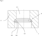
- Fig.3 shows a sectional view of the piston 2, which shows in particular the design of the inner ring groove 6 in more detail.
- the inner ring groove 6 is located in the inner wall in the axial bore 2.1 of the piston 2.
- the inner ring groove 6 comprises the coupling ring section 6.1 and the fixing ring section 6.2.
- the coupling ring section 6.1 provides the axial form-fitting connection between the coupling ring 3 and the piston 2.
- the undercut contour 6.3 is part of the fixing ring section 6.2 and ensures the axial positive connection of the fixing ring 4 with the piston 2.
- Fig.4 the coupling ring 3 with the piston rod 1 is shown in more detail.
- the coupling ring 3 is divided into two parts. The two halves of the coupling ring 3 are inserted into the outer ring groove 5.
- part of the coupling ring 3 (right) is shown as already inserted into the outer ring groove 5 and the other part of the piston ring 3 (left) is shown still disassembled.
- the arrow shows the radial assembly direction for this part of the coupling ring 3.
- the two parts of the two-part coupling ring 3 are inserted into the outer ring groove 5 of the piston rod 1 in the radial direction of movement.
- the piston 2 is then placed on the guide-side end of the piston rod 1 and moved on the piston rod 1 in the direction of the piston-bottom-side end 2.2 until the inner ring groove 6, which is open on one side, slides over the coupling ring 3 and the coupling ring 3 is arranged in the coupling ring groove space 7 formed by the coupling ring section 6.1 and the outer ring groove 5.
- the coupling ring 3 is now radially enclosed by the piston 2 with its inner ring groove and can no longer fall out of the outer ring groove 5.
- the outer contour of the coupling ring 3 fits positively in the outer ring groove 5 and in the coupling ring groove section 6.1, whereby the piston 2 is axially fixed in the pulling direction relative to the piston rod 1 and can transmit forces acting axially in the pulling direction to the piston rod 1 during operation.
- the flexible fixing ring 4 is pushed from the piston bottom end 2.2 of the piston 2 into the axial bore 2.2. When it reaches the fixing ring section 6.2, it spreads open and enters the fixing ring section 6.2. This creates a positive connection with the undercut contour 6.3 and the fixing ring 4.
- the fixing ring 4 is designed as a round ring in the first embodiment and as a flexible conical ring with an oval beveled cross-section in the second embodiment.
- FIGS. 5 and 6 show the fixing ring in a special design with a flattened radial cross-section 4.2.
- Figure 5 (a) shows a top view of the fixing ring 4.
- the fixing ring 4 has a fixing ring gap 4.1.
- FIG 5 (b) is a sectional view along the cutting plane (AA) of the fixing ring.
- This view shows the flattened radial cross section 4.2 of the fixing ring 1 in an enlarged view.
- the cross-sectional longitudinal axis 4.3 and the cross-sectional transverse axis 4.4 are inscribed in this cross section 4.2.
- the ring plane 4.5 runs through their intersection points.
- the outer diameter 4.8 and the inner diameter 4.9 are formed by rounded contours.
- the two boundaries parallel to the cross-sectional longitudinal axis 4.3 are formed by the two ring surfaces 4.6, 4.7, with the first ring surface 4.6 representing the radial inside and the second ring surface 4.7 representing the radial outside of the fixing ring 4.
- the angle ⁇ is enclosed between the cross-sectional longitudinal axis 4.3 and the ring plane 4.5.
- FIG 6 A functional diagram of the tensioned fixing ring 4 is shown.
- the upper part of the drawing shows the relaxed position and the lower part of the drawing shows the tension position (dashed).
- the representation is analogous to Figure 5 (b) .
- angle ⁇ In the stress position, the angle between the longitudinal axis of the cross-section 4.3 and the ring plane 4.5 increases. This angle in the stress position is designated as angle ⁇ in the lower section of the drawing.
- the axial overlap area 4.10 is limited by the inner and outer diameters 4.8, 4.9 of the fixing ring 4, which in Fig.6 is projected onto the ring plane 4.5.
- the axial overlap area 4.10 is shown outside the actual ring plane 4.5 by two vertical auxiliary lines on the inner diameter 4.8 and the outer diameter 4.9 for a better overview.
- the axial contact area 4.10 is reduced in the stress position.
- the axial contact area 4.10 is shown as a dashed bold line in the stress position and as a solid bold line in the relaxation position.
Landscapes
- Engineering & Computer Science (AREA)
- General Engineering & Computer Science (AREA)
- Mechanical Engineering (AREA)
- Pistons, Piston Rings, And Cylinders (AREA)
Applications Claiming Priority (1)
| Application Number | Priority Date | Filing Date | Title |
|---|---|---|---|
| DE202019003251.7U DE202019003251U1 (de) | 2019-08-05 | 2019-08-05 | Zugzylinderkolbeneinheit |
Publications (2)
| Publication Number | Publication Date |
|---|---|
| EP3772602A1 EP3772602A1 (de) | 2021-02-10 |
| EP3772602B1 true EP3772602B1 (de) | 2024-09-11 |
Family
ID=73547070
Family Applications (1)
| Application Number | Title | Priority Date | Filing Date |
|---|---|---|---|
| EP20000264.0A Active EP3772602B1 (de) | 2019-08-05 | 2020-07-23 | Zugzylinderkolbeneinheit |
Country Status (5)
| Country | Link |
|---|---|
| EP (1) | EP3772602B1 (pl) |
| DE (2) | DE202019003251U1 (pl) |
| DK (1) | DK3772602T3 (pl) |
| ES (1) | ES2996343T3 (pl) |
| PL (1) | PL3772602T3 (pl) |
Family Cites Families (9)
| Publication number | Priority date | Publication date | Assignee | Title |
|---|---|---|---|---|
| US3807285A (en) * | 1972-04-17 | 1974-04-30 | Cessna Aircraft Co | Connection between rod and piston of fluid power cylinder |
| JPS5191649U (pl) * | 1975-01-20 | 1976-07-22 | ||
| JPS61175662U (pl) * | 1985-03-26 | 1986-11-01 | ||
| DE102004008769B3 (de) * | 2004-02-23 | 2005-06-16 | Albrecht, Friedhelm | Stangenförmiger Körper mit daran befestigtem Teil |
| DE102004031777A1 (de) * | 2004-07-01 | 2006-01-26 | Battenfeld Gmbh | Verbindung für zwei Maschinenbauteile |
| DE202012008999U1 (de) * | 2012-09-19 | 2014-01-15 | Bümach Engineering International B.V. | Kolbeneinheit eines Arbeitszylinders |
| DE202012009001U1 (de) * | 2012-09-19 | 2014-01-15 | Bümach Engineering International B.V. | Arbeitszylinder |
| AU2015221444B2 (en) * | 2015-05-06 | 2020-07-02 | Ticbar Pty Ltd | A piston assembly |
| JP6606807B2 (ja) * | 2017-03-08 | 2019-11-20 | Smc株式会社 | 軸連結構造及び流体圧装置 |
-
2019
- 2019-08-05 DE DE202019003251.7U patent/DE202019003251U1/de active Active
-
2020
- 2020-07-23 DK DK20000264.0T patent/DK3772602T3/da active
- 2020-07-23 ES ES20000264T patent/ES2996343T3/es active Active
- 2020-07-23 EP EP20000264.0A patent/EP3772602B1/de active Active
- 2020-07-23 DE DE102020004458.1A patent/DE102020004458A1/de active Pending
- 2020-07-23 PL PL20000264.0T patent/PL3772602T3/pl unknown
Also Published As
| Publication number | Publication date |
|---|---|
| ES2996343T3 (en) | 2025-02-12 |
| PL3772602T3 (pl) | 2025-03-03 |
| DE202019003251U1 (de) | 2020-11-06 |
| DK3772602T3 (da) | 2024-12-02 |
| DE102020004458A1 (de) | 2021-02-11 |
| EP3772602A1 (de) | 2021-02-10 |
Similar Documents
| Publication | Publication Date | Title |
|---|---|---|
| DE3434763C2 (de) | Schraubkupplung für Ölfeldrohre | |
| DE10119534B4 (de) | Metallische Dichtung | |
| EP2683961B1 (de) | Durch materialverdrängung vorspannbare buchse und mit dieser buchse ausgestattetes lager | |
| DE112013004573B4 (de) | Kolbeneinheit eines Arbeitszylinders | |
| WO2014184291A2 (de) | BAUTEIL MIT MINDESTENS ZWEI MITEINANDER VERSCHWEIßTEN TEILEN | |
| AT519493A2 (de) | Dehnspannhülse, Werkzeughalter mit einer solchen Dehnspannhülse sowie Verfahren zum Spannen eines Werkzeugs | |
| AT519652B1 (de) | Dichtungsvorrichtung und Hydraulikkolben mit Dichtungsvorrichtung | |
| WO2018113810A1 (de) | Schraubarbeitszylinder | |
| WO2022083811A1 (de) | Endlagengedämpfter arbeitszylinder und dämpfungskolbenring | |
| EP4390207A1 (de) | Kupplungsteil für eine hydraulikkupplung | |
| EP3277977A1 (de) | Axialdämpfer | |
| EP3772604B1 (de) | Differenzialzylinderkolbeneinheit | |
| DE3418559C2 (de) | Schwenkverschraubung | |
| EP3772602A1 (de) | Zugzylinderkolbeneinheit | |
| WO2021058281A1 (de) | Dichtungsanordnung für einen filter, insbesondere einen druckluftfilter und filterelement für einen filter | |
| EP0412997A1 (de) | Dichtungsanordnung. | |
| DE102013221600A1 (de) | Radialgelenklager | |
| DE202009010326U1 (de) | Anordnung zur Abdichtung von Leitungen, Armaturen oder Aggregaten | |
| WO2000008367A2 (de) | Rohrverbindung | |
| DE10200018A1 (de) | Spieleinstellbares Gleitlager und Fluidzylinder mit einem solchen Gleitlager | |
| DE3809369A1 (de) | Vorrichtung zum zusammenfuegen | |
| DE102005055822B4 (de) | Hülsenanordnung | |
| EP3438472A1 (de) | Anordnung zur verbindung von gehäuseteilen mittels schrauben | |
| EP3772603B1 (de) | Kolbensicherungsring | |
| DE102022002094A1 (de) | Arbeitszylinder |
Legal Events
| Date | Code | Title | Description |
|---|---|---|---|
| PUAI | Public reference made under article 153(3) epc to a published international application that has entered the european phase |
Free format text: ORIGINAL CODE: 0009012 |
|
| STAA | Information on the status of an ep patent application or granted ep patent |
Free format text: STATUS: THE APPLICATION HAS BEEN PUBLISHED |
|
| AK | Designated contracting states |
Kind code of ref document: A1 Designated state(s): AL AT BE BG CH CY CZ DE DK EE ES FI FR GB GR HR HU IE IS IT LI LT LU LV MC MK MT NL NO PL PT RO RS SE SI SK SM TR |
|
| AX | Request for extension of the european patent |
Extension state: BA ME |
|
| STAA | Information on the status of an ep patent application or granted ep patent |
Free format text: STATUS: REQUEST FOR EXAMINATION WAS MADE |
|
| 17P | Request for examination filed |
Effective date: 20210810 |
|
| RBV | Designated contracting states (corrected) |
Designated state(s): AL AT BE BG CH CY CZ DE DK EE ES FI FR GB GR HR HU IE IS IT LI LT LU LV MC MK MT NL NO PL PT RO RS SE SI SK SM TR |
|
| GRAP | Despatch of communication of intention to grant a patent |
Free format text: ORIGINAL CODE: EPIDOSNIGR1 |
|
| STAA | Information on the status of an ep patent application or granted ep patent |
Free format text: STATUS: GRANT OF PATENT IS INTENDED |
|
| INTG | Intention to grant announced |
Effective date: 20240508 |
|
| GRAS | Grant fee paid |
Free format text: ORIGINAL CODE: EPIDOSNIGR3 |
|
| RAP3 | Party data changed (applicant data changed or rights of an application transferred) |
Owner name: BUEMACH ENGINEERING INTERNATIONAL B.V. |
|
| GRAA | (expected) grant |
Free format text: ORIGINAL CODE: 0009210 |
|
| STAA | Information on the status of an ep patent application or granted ep patent |
Free format text: STATUS: THE PATENT HAS BEEN GRANTED |
|
| AK | Designated contracting states |
Kind code of ref document: B1 Designated state(s): AL AT BE BG CH CY CZ DE DK EE ES FI FR GB GR HR HU IE IS IT LI LT LU LV MC MK MT NL NO PL PT RO RS SE SI SK SM TR |
|
| REG | Reference to a national code |
Ref country code: GB Ref legal event code: FG4D Free format text: NOT ENGLISH |
|
| REG | Reference to a national code |
Ref country code: CH Ref legal event code: EP |
|
| REG | Reference to a national code |
Ref country code: DE Ref legal event code: R096 Ref document number: 502020009150 Country of ref document: DE |
|
| REG | Reference to a national code |
Ref country code: IE Ref legal event code: FG4D Free format text: LANGUAGE OF EP DOCUMENT: GERMAN |
|
| REG | Reference to a national code |
Ref country code: NL Ref legal event code: FP |
|
| REG | Reference to a national code |
Ref country code: DK Ref legal event code: T3 Effective date: 20241125 |
|
| REG | Reference to a national code |
Ref country code: SE Ref legal event code: TRGR |
|
| REG | Reference to a national code |
Ref country code: LT Ref legal event code: MG9D |
|
| PG25 | Lapsed in a contracting state [announced via postgrant information from national office to epo] |
Ref country code: NO Free format text: LAPSE BECAUSE OF FAILURE TO SUBMIT A TRANSLATION OF THE DESCRIPTION OR TO PAY THE FEE WITHIN THE PRESCRIBED TIME-LIMIT Effective date: 20241211 |
|
| PG25 | Lapsed in a contracting state [announced via postgrant information from national office to epo] |
Ref country code: GR Free format text: LAPSE BECAUSE OF FAILURE TO SUBMIT A TRANSLATION OF THE DESCRIPTION OR TO PAY THE FEE WITHIN THE PRESCRIBED TIME-LIMIT Effective date: 20241212 Ref country code: FI Free format text: LAPSE BECAUSE OF FAILURE TO SUBMIT A TRANSLATION OF THE DESCRIPTION OR TO PAY THE FEE WITHIN THE PRESCRIBED TIME-LIMIT Effective date: 20240911 |
|
| PG25 | Lapsed in a contracting state [announced via postgrant information from national office to epo] |
Ref country code: BG Free format text: LAPSE BECAUSE OF FAILURE TO SUBMIT A TRANSLATION OF THE DESCRIPTION OR TO PAY THE FEE WITHIN THE PRESCRIBED TIME-LIMIT Effective date: 20240911 |
|
| PG25 | Lapsed in a contracting state [announced via postgrant information from national office to epo] |
Ref country code: LV Free format text: LAPSE BECAUSE OF FAILURE TO SUBMIT A TRANSLATION OF THE DESCRIPTION OR TO PAY THE FEE WITHIN THE PRESCRIBED TIME-LIMIT Effective date: 20240911 |
|
| PG25 | Lapsed in a contracting state [announced via postgrant information from national office to epo] |
Ref country code: HR Free format text: LAPSE BECAUSE OF FAILURE TO SUBMIT A TRANSLATION OF THE DESCRIPTION OR TO PAY THE FEE WITHIN THE PRESCRIBED TIME-LIMIT Effective date: 20240911 |
|
| PG25 | Lapsed in a contracting state [announced via postgrant information from national office to epo] |
Ref country code: RS Free format text: LAPSE BECAUSE OF FAILURE TO SUBMIT A TRANSLATION OF THE DESCRIPTION OR TO PAY THE FEE WITHIN THE PRESCRIBED TIME-LIMIT Effective date: 20241211 |
|
| PG25 | Lapsed in a contracting state [announced via postgrant information from national office to epo] |
Ref country code: RS Free format text: LAPSE BECAUSE OF FAILURE TO SUBMIT A TRANSLATION OF THE DESCRIPTION OR TO PAY THE FEE WITHIN THE PRESCRIBED TIME-LIMIT Effective date: 20241211 Ref country code: NO Free format text: LAPSE BECAUSE OF FAILURE TO SUBMIT A TRANSLATION OF THE DESCRIPTION OR TO PAY THE FEE WITHIN THE PRESCRIBED TIME-LIMIT Effective date: 20241211 Ref country code: LV Free format text: LAPSE BECAUSE OF FAILURE TO SUBMIT A TRANSLATION OF THE DESCRIPTION OR TO PAY THE FEE WITHIN THE PRESCRIBED TIME-LIMIT Effective date: 20240911 Ref country code: HR Free format text: LAPSE BECAUSE OF FAILURE TO SUBMIT A TRANSLATION OF THE DESCRIPTION OR TO PAY THE FEE WITHIN THE PRESCRIBED TIME-LIMIT Effective date: 20240911 Ref country code: GR Free format text: LAPSE BECAUSE OF FAILURE TO SUBMIT A TRANSLATION OF THE DESCRIPTION OR TO PAY THE FEE WITHIN THE PRESCRIBED TIME-LIMIT Effective date: 20241212 Ref country code: FI Free format text: LAPSE BECAUSE OF FAILURE TO SUBMIT A TRANSLATION OF THE DESCRIPTION OR TO PAY THE FEE WITHIN THE PRESCRIBED TIME-LIMIT Effective date: 20240911 Ref country code: BG Free format text: LAPSE BECAUSE OF FAILURE TO SUBMIT A TRANSLATION OF THE DESCRIPTION OR TO PAY THE FEE WITHIN THE PRESCRIBED TIME-LIMIT Effective date: 20240911 |
|
| REG | Reference to a national code |
Ref country code: ES Ref legal event code: FG2A Ref document number: 2996343 Country of ref document: ES Kind code of ref document: T3 Effective date: 20250212 |
|
| PG25 | Lapsed in a contracting state [announced via postgrant information from national office to epo] |
Ref country code: PT Free format text: LAPSE BECAUSE OF FAILURE TO SUBMIT A TRANSLATION OF THE DESCRIPTION OR TO PAY THE FEE WITHIN THE PRESCRIBED TIME-LIMIT Effective date: 20250113 Ref country code: IS Free format text: LAPSE BECAUSE OF FAILURE TO SUBMIT A TRANSLATION OF THE DESCRIPTION OR TO PAY THE FEE WITHIN THE PRESCRIBED TIME-LIMIT Effective date: 20250111 |
|
| PG25 | Lapsed in a contracting state [announced via postgrant information from national office to epo] |
Ref country code: RO Free format text: LAPSE BECAUSE OF FAILURE TO SUBMIT A TRANSLATION OF THE DESCRIPTION OR TO PAY THE FEE WITHIN THE PRESCRIBED TIME-LIMIT Effective date: 20240911 Ref country code: SM Free format text: LAPSE BECAUSE OF FAILURE TO SUBMIT A TRANSLATION OF THE DESCRIPTION OR TO PAY THE FEE WITHIN THE PRESCRIBED TIME-LIMIT Effective date: 20240911 |
|
| PG25 | Lapsed in a contracting state [announced via postgrant information from national office to epo] |
Ref country code: EE Free format text: LAPSE BECAUSE OF FAILURE TO SUBMIT A TRANSLATION OF THE DESCRIPTION OR TO PAY THE FEE WITHIN THE PRESCRIBED TIME-LIMIT Effective date: 20240911 |
|
| PG25 | Lapsed in a contracting state [announced via postgrant information from national office to epo] |
Ref country code: CZ Free format text: LAPSE BECAUSE OF FAILURE TO SUBMIT A TRANSLATION OF THE DESCRIPTION OR TO PAY THE FEE WITHIN THE PRESCRIBED TIME-LIMIT Effective date: 20240911 |
|
| PG25 | Lapsed in a contracting state [announced via postgrant information from national office to epo] |
Ref country code: SK Free format text: LAPSE BECAUSE OF FAILURE TO SUBMIT A TRANSLATION OF THE DESCRIPTION OR TO PAY THE FEE WITHIN THE PRESCRIBED TIME-LIMIT Effective date: 20240911 |
|
| REG | Reference to a national code |
Ref country code: DE Ref legal event code: R097 Ref document number: 502020009150 Country of ref document: DE |
|
| PGFP | Annual fee paid to national office [announced via postgrant information from national office to epo] |
Ref country code: PL Payment date: 20250609 Year of fee payment: 6 |
|
| PGFP | Annual fee paid to national office [announced via postgrant information from national office to epo] |
Ref country code: GB Payment date: 20250501 Year of fee payment: 6 Ref country code: DK Payment date: 20250526 Year of fee payment: 6 |
|
| PGFP | Annual fee paid to national office [announced via postgrant information from national office to epo] |
Ref country code: IT Payment date: 20250505 Year of fee payment: 6 |
|
| PLBE | No opposition filed within time limit |
Free format text: ORIGINAL CODE: 0009261 |
|
| STAA | Information on the status of an ep patent application or granted ep patent |
Free format text: STATUS: NO OPPOSITION FILED WITHIN TIME LIMIT |
|
| PGFP | Annual fee paid to national office [announced via postgrant information from national office to epo] |
Ref country code: SE Payment date: 20250520 Year of fee payment: 6 |
|
| PGFP | Annual fee paid to national office [announced via postgrant information from national office to epo] |
Ref country code: NL Payment date: 20250728 Year of fee payment: 6 |
|
| 26N | No opposition filed |
Effective date: 20250612 |
|
| PGFP | Annual fee paid to national office [announced via postgrant information from national office to epo] |
Ref country code: ES Payment date: 20250801 Year of fee payment: 6 |
|
| PGFP | Annual fee paid to national office [announced via postgrant information from national office to epo] |
Ref country code: DE Payment date: 20250731 Year of fee payment: 6 |
|
| PGFP | Annual fee paid to national office [announced via postgrant information from national office to epo] |
Ref country code: FR Payment date: 20250717 Year of fee payment: 6 Ref country code: AT Payment date: 20250702 Year of fee payment: 6 |
|
| PGFP | Annual fee paid to national office [announced via postgrant information from national office to epo] |
Ref country code: CH Payment date: 20250801 Year of fee payment: 6 |
|
| REG | Reference to a national code |
Ref country code: DE Ref legal event code: R082 Ref document number: 502020009150 Country of ref document: DE Representative=s name: WEIHRAUCH, FRANK, DR., DE |
|
| PG25 | Lapsed in a contracting state [announced via postgrant information from national office to epo] |
Ref country code: LU Free format text: LAPSE BECAUSE OF NON-PAYMENT OF DUE FEES Effective date: 20250723 |
|
| PG25 | Lapsed in a contracting state [announced via postgrant information from national office to epo] |
Ref country code: LT Free format text: LAPSE BECAUSE OF FAILURE TO SUBMIT A TRANSLATION OF THE DESCRIPTION OR TO PAY THE FEE WITHIN THE PRESCRIBED TIME-LIMIT Effective date: 20240911 |
|
| PG25 | Lapsed in a contracting state [announced via postgrant information from national office to epo] |
Ref country code: IE Free format text: LAPSE BECAUSE OF NON-PAYMENT OF DUE FEES Effective date: 20250723 |
|
| PGFP | Annual fee paid to national office [announced via postgrant information from national office to epo] |
Ref country code: BE Payment date: 20260617 Year of fee payment: 7 |
|
| PG25 | Lapsed in a contracting state [announced via postgrant information from national office to epo] |
Ref country code: MC Free format text: LAPSE BECAUSE OF FAILURE TO SUBMIT A TRANSLATION OF THE DESCRIPTION OR TO PAY THE FEE WITHIN THE PRESCRIBED TIME-LIMIT Effective date: 20240911 |
|
| PG25 | Lapsed in a contracting state [announced via postgrant information from national office to epo] |
Ref country code: CY Free format text: LAPSE BECAUSE OF FAILURE TO SUBMIT A TRANSLATION OF THE DESCRIPTION OR TO PAY THE FEE WITHIN THE PRESCRIBED TIME-LIMIT Effective date: 20240911 |