EP3772588A1 - Bloc modulaire pour pompe électrique à encombrement limité et pompe associée - Google Patents
Bloc modulaire pour pompe électrique à encombrement limité et pompe associée Download PDFInfo
- Publication number
- EP3772588A1 EP3772588A1 EP20189763.4A EP20189763A EP3772588A1 EP 3772588 A1 EP3772588 A1 EP 3772588A1 EP 20189763 A EP20189763 A EP 20189763A EP 3772588 A1 EP3772588 A1 EP 3772588A1
- Authority
- EP
- European Patent Office
- Prior art keywords
- housing
- axis
- main body
- modular block
- plane
- Prior art date
- Legal status (The legal status is an assumption and is not a legal conclusion. Google has not performed a legal analysis and makes no representation as to the accuracy of the status listed.)
- Pending
Links
Images



Classifications
-
- F—MECHANICAL ENGINEERING; LIGHTING; HEATING; WEAPONS; BLASTING
- F04—POSITIVE - DISPLACEMENT MACHINES FOR LIQUIDS; PUMPS FOR LIQUIDS OR ELASTIC FLUIDS
- F04B—POSITIVE-DISPLACEMENT MACHINES FOR LIQUIDS; PUMPS
- F04B53/00—Component parts, details or accessories not provided for in, or of interest apart from, groups F04B1/00 - F04B23/00 or F04B39/00 - F04B47/00
- F04B53/16—Casings; Cylinders; Cylinder liners or heads; Fluid connections
-
- F—MECHANICAL ENGINEERING; LIGHTING; HEATING; WEAPONS; BLASTING
- F04—POSITIVE - DISPLACEMENT MACHINES FOR LIQUIDS; PUMPS FOR LIQUIDS OR ELASTIC FLUIDS
- F04B—POSITIVE-DISPLACEMENT MACHINES FOR LIQUIDS; PUMPS
- F04B15/00—Pumps adapted to handle specific fluids, e.g. by selection of specific materials for pumps or pump parts
- F04B15/02—Pumps adapted to handle specific fluids, e.g. by selection of specific materials for pumps or pump parts the fluids being viscous or non-homogeneous
-
- F—MECHANICAL ENGINEERING; LIGHTING; HEATING; WEAPONS; BLASTING
- F04—POSITIVE - DISPLACEMENT MACHINES FOR LIQUIDS; PUMPS FOR LIQUIDS OR ELASTIC FLUIDS
- F04B—POSITIVE-DISPLACEMENT MACHINES FOR LIQUIDS; PUMPS
- F04B17/00—Pumps characterised by combination with, or adaptation to, specific driving engines or motors
- F04B17/03—Pumps characterised by combination with, or adaptation to, specific driving engines or motors driven by electric motors
-
- F—MECHANICAL ENGINEERING; LIGHTING; HEATING; WEAPONS; BLASTING
- F04—POSITIVE - DISPLACEMENT MACHINES FOR LIQUIDS; PUMPS FOR LIQUIDS OR ELASTIC FLUIDS
- F04B—POSITIVE-DISPLACEMENT MACHINES FOR LIQUIDS; PUMPS
- F04B43/00—Machines, pumps, or pumping installations having flexible working members
- F04B43/02—Machines, pumps, or pumping installations having flexible working members having plate-like flexible members, e.g. diaphragms
- F04B43/025—Machines, pumps, or pumping installations having flexible working members having plate-like flexible members, e.g. diaphragms two or more plate-like pumping members in parallel
- F04B43/026—Machines, pumps, or pumping installations having flexible working members having plate-like flexible members, e.g. diaphragms two or more plate-like pumping members in parallel each plate-like pumping flexible member working in its own pumping chamber
-
- F—MECHANICAL ENGINEERING; LIGHTING; HEATING; WEAPONS; BLASTING
- F04—POSITIVE - DISPLACEMENT MACHINES FOR LIQUIDS; PUMPS FOR LIQUIDS OR ELASTIC FLUIDS
- F04B—POSITIVE-DISPLACEMENT MACHINES FOR LIQUIDS; PUMPS
- F04B43/00—Machines, pumps, or pumping installations having flexible working members
- F04B43/02—Machines, pumps, or pumping installations having flexible working members having plate-like flexible members, e.g. diaphragms
- F04B43/04—Pumps having electric drive
-
- F—MECHANICAL ENGINEERING; LIGHTING; HEATING; WEAPONS; BLASTING
- F04—POSITIVE - DISPLACEMENT MACHINES FOR LIQUIDS; PUMPS FOR LIQUIDS OR ELASTIC FLUIDS
- F04B—POSITIVE-DISPLACEMENT MACHINES FOR LIQUIDS; PUMPS
- F04B53/00—Component parts, details or accessories not provided for in, or of interest apart from, groups F04B1/00 - F04B23/00 or F04B39/00 - F04B47/00
- F04B53/14—Pistons, piston-rods or piston-rod connections
-
- F—MECHANICAL ENGINEERING; LIGHTING; HEATING; WEAPONS; BLASTING
- F05—INDEXING SCHEMES RELATING TO ENGINES OR PUMPS IN VARIOUS SUBCLASSES OF CLASSES F01-F04
- F05B—INDEXING SCHEME RELATING TO WIND, SPRING, WEIGHT, INERTIA OR LIKE MOTORS, TO MACHINES OR ENGINES FOR LIQUIDS COVERED BY SUBCLASSES F03B, F03D AND F03G
- F05B2210/00—Working fluid
- F05B2210/10—Kind or type
- F05B2210/11—Kind or type liquid, i.e. incompressible
-
- F—MECHANICAL ENGINEERING; LIGHTING; HEATING; WEAPONS; BLASTING
- F05—INDEXING SCHEMES RELATING TO ENGINES OR PUMPS IN VARIOUS SUBCLASSES OF CLASSES F01-F04
- F05B—INDEXING SCHEME RELATING TO WIND, SPRING, WEIGHT, INERTIA OR LIKE MOTORS, TO MACHINES OR ENGINES FOR LIQUIDS COVERED BY SUBCLASSES F03B, F03D AND F03G
- F05B2260/00—Function
- F05B2260/40—Transmission of power
Definitions
- the present invention relates to a modular unit for an electric pump for a fluid product, in particular for paint, and an associated electric pump.
- fluid product is understood here and hereinafter to mean a product which has a viscosity of between 1 mPa.s and 300,000 mPa.s, this viscosity being for example measured using a Brookfield Plan Cone viscometer in normal temperature and pressure conditions. This expression thus groups together products in the liquid state, perfectly deformable and of low viscosity, but also products generally qualified as "pasty", more viscous than liquids and having an intermediate state between the liquid state and the solid state. .
- Such a pump is, for example, suitable for circulating paint in a circuit. This makes it possible in particular to prevent sedimentation of the paint and to maintain the paint homogeneous.
- the pump must be suitable for the desired circulation rate. In particular, if the pump is not matched to the flow, there is a risk that the pump will run too fast and cause the paint to laminate, or the pump will run too slowly and the paint will not be homogeneous.
- the modules are, for example, superimposed along a shaft of the electric motor.
- An object of the invention is to provide a pump system that can be adapted to different ranges of flow rate having limited bulk.
- the symmetries of the modular block make it possible to superimpose two identical modular blocks so that the respective second planes extend in the same plane and by alternating the location of the housing relative to said plane, and thus of the pumping device. Since the general size of the modular block depends on the size of the pumping device, the alternating arrangement of the pumping devices offers the possibility of reducing the size of the superposition of the modular blocks in the direction of superposition.
- the invention further relates to a modular unit for an electric pump comprising a main body and a pumping device, the main body having a general shape exhibiting orthogonal symmetry with respect to a plane, the pumping device being placed outside said plane. on one side of said plane, the modular block exhibiting reversibility with respect to a reversion axis included in the plane.
- the invention further relates to an electric pump for a fluid product comprising an electric motor and at least two modular blocks as defined above, the modular blocks being identical and placed side by side so that their general shapes are superimposed in a direction of elevation, their respective central planes merging into a common central plane, the modular blocks being placed so that the main axes are placed alternately on a first side and a second side of the common central plane.
- a modular block 10 for an electric pump for a fluid product is shown in figure 1 and visible on figures 2 to 6 .
- the modular block 10 includes a main body 12 and a pumping device 14.
- the modular unit 10 is designed to cooperate with the shaft of a motor extending in a so-called direction of elevation Z.
- a longitudinal direction X and a transverse direction Y are defined which are perpendicular to each other and perpendicular to the direction of elevation Z, so as to define an orthogonal coordinate system.
- the main body 12 comprises one or, here, outer side walls 16.
- the main body 12 further comprises an internal side wall 17 and here an intermediate partition 18.
- the main body 12 has a general shape.
- the general shape is here defined by the outer side wall or walls 16.
- the outer side walls 16 extend here in the direction of elevation Z.
- the outer side walls 16 have a dimension in the direction of elevation Z, said dimension being called height, constant over all of the walls.
- the general shape has discrete rotational symmetry with respect to an axis of reversion ⁇ , more particularly for an angle of rotation substantially equal to 180 °.
- the general shape has orthogonal symmetry with respect to a first plane P h and with respect to a second plane P v .
- the second plane P v is perpendicular to the first plane P h .
- the axis of reversion ⁇ corresponds here to the intersection of the first plane P h and the second plane P v .
- the first plane P h extends in the longitudinal direction X and in the transverse direction Y.
- the second plane P v extends in the transverse direction Y and in the direction of elevation Z.
- the second plane P v separates the space into two halves along a first side E 1 of the second plane and a second side E 2 of the second plane.
- the second plane P v is also called the central plane.
- the internal side wall 17 defines a through hole 20 passing through the modular block 10.
- the through orifice 20 passes through the modular block 10 in the direction of elevation Z.
- the main body 12 is configured to receive the motor shaft in the through hole 20.
- the inner side wall 17 has a constant height, more particularly equal to the height of the outer side walls.
- the inner side wall 17 is flush with the outer side walls 16.
- the inner side wall 17 is included in the general shape.
- the inner side wall 17 is in contact with the outer side wall (s) 16 at a location 21 included in the second plane P v .
- the through orifice 20 has a central axis D, extending here in the direction of elevation Z.
- the through orifice 20 has an orthogonal symmetry with respect to the first plane P h and with respect to the second plane P v .
- the internal side wall 17 is here a cylinder with a circular base having as an axis of revolution the central axis D of the through orifice 20.
- the main body 12, more particularly the inner side wall 17, has a bore 23 at each end of the through hole 20 in the direction of elevation Z.
- the bore 23 here extends over the face of the inner side wall. 17 delimiting the through-hole 20.
- the intermediate partition 18 is here a central partition of the main body 12, that is to say that it extends halfway up the main body 12 in the direction of elevation Z.
- the intermediate partition 18 here extends along the foreground P h .
- the intermediate partition 18 then separates the modular block 10 into two halves 22, here orthogonally symmetrical.
- the modular block 10, more particularly the intermediate partition 18, the outer side walls 16 and the inner side wall 17, defines for each half 22 an open volume 24.
- the open volume 24 is open opposite the intermediate partition 18 according to the direction of elevation Z.
- Each open volume 24 is adaptable to form a fluid reservoir.
- each open volume 24 has a suction opening 25 and a delivery opening 27.
- the suction opening 25 is located close to the intermediate partition 18, the discharge opening 27 being further from the intermediate partition 18 than the suction opening 25.
- the modular block 10 also has one or more reinforcing ribs 26 and / or one or more radial partitions 28.
- Each reinforcing rib 26 connects the internal side wall 17 to the intermediate partition 18.
- Each radial partition 28 connects the or one of the outer side walls 16 and the inner side wall 17 over the entire height of the main body 12.
- the radial partition 28 thus extends on either side of the intermediate partition 18. .
- the main body 12 does not include an intermediate partition 18 as described above, but another arrangement defining at least one volume capable of being adapted to form a fluid reservoir.
- the main body 12 includes, for example, a first half-bottom and a second half-bottom.
- the first half-bottom extends at a first end of the main body in the direction of elevation Z in the first half E 1 of the space.
- the second half-bottom extends at a second end of the main body in the direction of elevation Z, opposite the first end, in the second half E 2 of the space.
- the main body 12 further defines a housing 30, the housing being provided to receive the pumping device 14.
- the housing 30 is arranged between the inner side wall 17 and the and one or more outer side walls 16.
- the housing 30 extends opposite the location 21 of contact between the inner side wall 17 and the outer side wall (s) 16 in the longitudinal direction X.
- the housing 30 extends along a main axis ⁇ included in the first plane P h . More particularly, the housing 30 has a so-called proximal end at the level of the through-orifice 20 and a so-called distal end opposite the proximal end in the direction of the main axis ⁇ .
- the main axis ⁇ of the housing 30 within the housing 30 extends on one side of the second plane P v , more particularly on the example of figure 1 on the first side E 1 .
- the main axis ⁇ of the housing 30 within the housing 30 extends outside the second plane P v , that is to say that the point forming the intersection between the main axis ⁇ and the second plane P v is located outside the accommodation.
- intersection between the main axis ⁇ and the second plane P v is more particularly located in the through-hole 20, more particularly at the level of the central axis D of the through-hole 20.
- the housing 30 opens into the through orifice 20 on the one hand and outside the main body 12 on the other hand.
- the housing 30 has an orthogonal symmetry with respect to the first plane P h .
- the main axis ⁇ of the housing 30 defines an angle ⁇ with the second plane P v .
- the distance in the transverse direction Y from the main axis ⁇ within the housing 30 to the second plane P v is strictly increasing from the proximal end towards the distal end.
- the housing 30 is here delimited by a hollow cylinder having as its axis of rotation the main axis ⁇ .
- the housing 30 has a shoulder 32 visible on the figure 2 near the through hole 20.
- the main body 12 as a whole has an orthogonal symmetry with respect to the first plane P h .
- the main body 12 has a reversibility by rotation around the axis of reversion ⁇ by a given angle called here the angle of reversion.
- the angle of reversion is equal to 180 °. This will be described in more detail below with regard to the operation of the modular block.
- the main body 12 here has a height h 12 equal to 120 millimeters.
- the main body 12 is, for example, made of aluminum or stainless steel.
- the pumping device 14 extends partially into the housing 30 of the main body 12.
- the pumping device 14 has an orthogonal symmetry with respect to the first plane P h .
- the pumping device 14 extends outside the second plane P v .
- the pumping device 14 comprises a piston 40 and a diaphragm 42.
- the piston 40 extends at least partially in the housing 30.
- the diaphragm 42 extends outside the housing 30 opposite the through orifice 20.
- the diaphragm 42 extends outside the general shape of the main body 12.
- the pumping device 14 further comprises a jacket 44 in which the piston 40 moves and / or a return member 46 of the piston 40.
- the pumping device 14 further comprises a base 48 for the diaphragm 42 and / or a closing partition 50.
- the diaphragm 42 extends between the base 48 and the closing partition 50.
- the jacket 44 and, where appropriate, the base 48 and the closing partition 50 are, for example, made of aluminum and / or stainless steel.
- the jacket 44 extends at least partially into the housing 30.
- the sleeve 44 extends between a proximal end of the side of the through-port 20 and a distal end of the side of the diaphragm 42.
- the proximal end of the sleeve 44 bears against the shoulder 32 of the housing 30.
- the sleeve 44 extends partially outside the housing 30. More particularly, the distal end of the sleeve 44 extends outside the housing 30.
- the sleeve 44 defines an internal volume.
- the liner 44 is a hollow cylinder, the axis of the cylinder being advantageously coincident with the main axis ⁇ .
- the outer diameter of the liner 44 is substantially equal to the diameter of the cylinder forming the housing 30.
- the jacket 44 forms a coating of the orifice forming the housing 30.
- the piston extends fully into the liner 44 and at least partially into the housing 30.
- the sleeve 44 cooperates with the piston 40 so that the piston 40 is able to slide in the sleeve 44, the sleeve 44 forming the complementary cylinder of the piston 40.
- the piston 40 is able to slide in translation in the sleeve 44 in the direction of the main axis ⁇ .
- the piston 40 separates the internal volume of the sleeve 44 into a proximal chamber 52 on the side of the through-port 20 and a distal chamber 54 on the side of the diaphragm 42.
- Distal chamber 54 contains transmission fluid.
- the piston 40 is movable in translation between two extreme positions: a so-called suction position shown in figure 2 and a so-called expulsion position.
- the volume of the distal chamber 54 in the aspiration position is strictly greater than the volume of the distal chamber 54 in the expulsion position of a given displacement, for example between 50 cL and 500 cL.
- the piston 40 in the suction position visible on the figure 2 , the piston 40 is substantially flush with the liner 44 on the side of the through-hole 20, more particularly here rests against an end shoulder 55 of the liner 44.
- the piston In the expulsion position, the piston is substantially flush with the liner 44 on the side of the diaphragm 42.
- the return member 46 of the piston 40 is arranged to return the piston 40 to the suction position.
- the return member 46 is here a spring working in extension.
- the return member 46 extends between a bearing surface 58 of the piston 40 and a shoulder 60 formed at the level of the distal end of the sleeve 44.
- the shoulder 60 is formed by the base 48.
- the pedestal 48 extends contiguously with the sleeve 44 at the distal end of said sleeve 44.
- the base 48 has a support surface 62 for the diaphragm 42.
- the support surface 62 is arranged on the base 48 opposite the liner 44 in the direction of the main axis ⁇ of the housing 30.
- the support surface 62 is curved and concave.
- the support surface 62 has a continuous rotational symmetry around the main axis ⁇ .
- the support surface 62 generally has the shape of a bowl.
- a central portion of the support surface 62 extends against the distal end of the liner 44.
- the support surface 62 further includes a peripheral portion surrounding the central portion.
- the base 48 has a plurality of through openings 64 between the internal volume of the jacket 44 and the support surface 62.
- the peripheral part of the support surface 62 has no opening.
- the base 48 is here fixed to the main body 12.
- the closing partition 50 extends facing the base 48 along the main axis ⁇ . It has a curvature in the opposite direction of the base.
- the base 48 and the closing partition 50 define a volume between them, here having the shape of a spindle.
- the closing partition 50 has two so-called connection openings 65 allowing the entry and / or the exit of fluid through the closing partition. More particularly, one of the openings called the inlet opening allows the entry of fluid while the other of the openings called the outlet opening allows the outlet of fluid.
- the closing partition 50 outside the connection openings 65 has a continuous rotational symmetry around the main axis ⁇ .
- Each opening 65 here extends parallel to the first plane P h .
- Each opening 65 here extends parallel to the second plane P v . More particularly, each opening 65 defines an angle ⁇ with the main axis ⁇ of the housing 30, said angle ⁇ being additional to the angle ⁇ defines between the main axis ⁇ of the housing 30 and the second plane P v .
- connection opening 65 has a valve system (not visible) in order to be able to respectively regulate the inlet or the outlet of fluid through the opening.
- Each valve system is able to close the opening in a closed position.
- Each valve system includes a system for returning the valve to the closed position.
- the return system is, for example, mechanical using a spring and / or magnetic and / or electromagnetic.
- the valve system is adapted to allow fluid to pass through the opening in the desired direction when a pressing force corresponding to the desired direction and greater than a given force is established on the valve system.
- such a valve system comprising a return system does not require any particular orientation, the latter not operating in particular by gravity.
- the diaphragm 42 extends between the base 48 and the closing partition 50, more particularly in the volume delimited between the base 48 and the closing partition 50.
- the diaphragm 42 is fixed on its periphery to the peripheral part of the base 48 and to the peripheral part of the closing partition 50.
- the diaphragm 42 is hermetic.
- connection openings 65 fluidly communicate with the exterior volume 68.
- the diaphragm 42 is able to deform under a pressure difference between the communicating volume 66 and the external volume 68.
- the diaphragm When the pressure of the communicating volume 66 is equal to the external volume 68 called the iso-pressure case, the diaphragm extends for example substantially along a plane parallel to the direction of elevation Z.
- the pressure of the external volume 68 decreases. This causes the valve system to open from the inlet opening and fluid enters the exterior volume 68.
- the diaphragm 42 has a dimension in the direction of elevation Z that is strictly greater than that of the main body 12.
- the non-deformed diaphragm 42 is here a disc with a central axis the main axis ⁇ .
- the diaphragm 42 here has a diameter D 42 strictly greater than 120 millimeters, more particularly greater than or equal to 250 millimeters.
- the diaphragm 42 also has a so-called wet diameter D M 42 greater than or equal to 100 millimeters, more particularly greater than or equal to 150 millimeters.
- the term “wet diameter” is understood to mean the diameter of the diaphragm in contact with the communicating volume 66 and the external volume 68. The wetted diameter corresponds to the diameter of the surface of the deforming diaphragm.
- the angle ⁇ between the main axis ⁇ of the housing and the second plane P v is chosen such that the diaphragm extends entirely outside the second plane P v .
- the angle ⁇ depends in particular on the diameter of the diaphragm and on the distance from the diaphragm to the through orifice 20.
- the angle ⁇ is, for example, greater than or equal to 20 °.
- the diaphragm 42 extends outside the general shape of the main body 12 thus makes it possible to reduce the dimension in the direction of elevation Z of the main body 12 to a smaller dimension than if the diaphragm 42 extended to inside the main body 12.
- Each modular block has a reversibility by rotation around the axis of reversion ⁇ , that is to say that the modular block can be used in a first configuration and in a second configuration, the modular block having undergone a rotation of a given angle around the axis of reversion ⁇ between the first configuration and the second configuration.
- the given angle of reversion is here equal to 180 °. More particularly here, it suffices to change the piping and connection system to the modular block to make the modular block usable in one or the other of the configurations.
- Each functional part of the modular block is either common and usable in both configurations, such as the pumping device, or is present in duplicate, such as, in the case shown, the open volume with the corresponding openings.
- the main body 12, the base 48 for the diaphragm 42 and the closing partition 50 are reversible with respect to the axis of reversion ⁇ .
- the pumping device is offset relative to the second plane P v of the main body.
- the pump is sized to operate up to a pressure of 30 bars.
- the pump 100 comprises an electric motor 102 and at least two modular blocks 104, 106 as described above.
- the pump 100 comprises two modular blocks 104, 106.
- the modular blocks 104, 106 are identical, that is to say they are formed on the same model with the same dimensions.
- the outer and inner side walls of the various modular blocks are aligned in the direction of elevation Z.
- the direction of elevation Z is, in the example shown, substantially parallel to the direction of local gravity.
- the direction of elevation Z is, for example, perpendicular to the direction of local gravity. Gaskets are advantageously provided between the modular blocks.
- the respective second planes of the modular blocks 104, 106 merge into a second common plane P v .
- the respective first planes of the modular blocks 104, 106 are mutually parallel.
- the respective main axes ⁇ 1 , ⁇ 2 of the modular blocks 104, 106 within the respective housings are placed alternately on a first side 108 and on a second side 110 of the second common plane P v .
- the main axis ⁇ 1 of a first modular block 104 in the corresponding housing is placed on the first side 108 of the second plane P v . and the main axis ⁇ 2 of the second modular block 106 in the corresponding housing is placed on the second side 110 of the second plane P v .
- the diaphragms of the respective pumping devices of the modular blocks 104, 106 are placed alternately on the first side 108 or on the second side 110 of the second common plane P v .
- the diaphragms are staggered on either side of the second common plane P v .
- Each modular block is turned over relative to the adjacent modular block (s) along the corresponding reversion axis ⁇ .
- Each modular block is adapted to operate according to its arrangement within the pump.
- each modular block is suitable for being connected at the level of the connection openings to a fluid product circulation circuit.
- the different connectors and pipes connected to each modular block are adapted for the given layout.
- valve systems of the connection openings are arranged so that the lower opening 112, 114 in the direction of elevation Z is the inlet opening and the upper opening 116, 118 is the inlet opening. outlet opening.
- the open volume of the half located above the intermediate partition in the direction of elevation Z here acts as a base reservoir and is connected to the communicating volume.
- the open volume of the upper half contains for example the same transmission fluid contained in the communicating volume, so as to be able to supply fluid to the communicating volume on the one hand and to allow the fluid to be expelled from the communicating volume.
- the suction opening and the discharge opening of the corresponding open volume are connected to the communicating volume by means of connectors and pipes.
- the suction opening and the discharge opening of the other open volume are blocked.
- the pump here comprises, for each modular block, a suction connection 120, 122 comprising an orifice and a plug, the orifice being designed to be placed facing the suction opening of the reservoir and the plug facing to the suction opening of the other open volume.
- the pump further comprises, for each modular block, a discharge connection 124, 126 connected to the discharge opening of the reservoir and a plug 128, 130 provided to close the discharge opening of the other open volume.
- one or more reservoirs are formed from a volume arranged differently than in the example shown.
- the reservoir extends, for example, over the height of two modular blocks on half of each block, suction and discharge openings being provided on each half.
- Each reservoir has, for example, a volume greater than or equal to the maximum volume of transmission fluid to fill the entire space containing transmission fluid, such as the communicating volume and the cylinder capacity.
- the or all of the reservoirs have a reversibility by rotation about the axis of reversion ⁇ of the angle of reversion.
- the pump 100 further comprises a bearing 132 at each interface between two adjacent modular blocks 104, 106 as shown in figure 4 .
- the bearing 132 spans the two modular blocks.
- each modular block at one end of the through hole is complementary to half of the bearing, the bearing being arranged in a bore of each of the modular blocks at the interface.
- the pump 100 further comprises a lower plate 134 and an upper plate 136, arranged on each side of the superposition of the modular blocks 104, 106 in the direction of elevation Z.
- the lower plate 134 and the upper plate 136 have a general shape that can be superimposed on that of the modular blocks.
- the lower plate 134 and the upper plate 136 close the pump 100 on either side of the modular blocks 104, 106.
- the pump 100 comprises a shaft (not visible) extending in the direction of elevation Z through the through orifices of the modular blocks 104, 106 and movable in rotation around the direction of elevation Z by the electric motor 102.
- the pump further comprises, for each modular block, means for transmitting the rotational movement of the shaft in a translational movement at said modular block in the direction of elevation.
- the transmission means comprises, for example, a connecting rod and crank system, an eccentric or a cam.
- the transmission means is integral with the shaft rotating around the direction of elevation Z on the one hand and provided to interact with the pumping device of the modular block on the other hand.
- the transmission means is designed to move the piston between the suction position and the expulsion position and then vice versa, by rotating the shaft in the same operating direction of the engine.
- each modular block 104, 106 are connected to a fluid product circulation circuit, the outlet opening being provided to expel the fluid product at a flow rate given in the circulation circuit and the inlet opening to suck the fluid.
- the modular blocks 104, 106 are connected to the same fluid product circulation circuit, so as to multiply the flow rate in the circulation circuit.
- the modular blocks 104, 106 are connected to separate circulation circuits, for example containing different fluid products.
- some modular blocks are connected to the same fluid product circulation circuit and at least one of the modular blocks is connected to a separate circulation circuit.
- the electric motor 102 drives the pump shaft in rotation around the direction of elevation Z, more particularly at a constant speed of rotation.
- the piston of each modular block is moved via the transmission means between the suction position and the expulsion position and then vice versa.
- the pump For each modular block, at each cycle, the pump sucks and delivers for this modular block a given volume of fluid, corresponding here to the displacement of the associated pumping device.
- a second and a third examples of an electric pump for a fluid product according to the invention are shown in the figures 5 and 6 .
- Said pumps differ only from the pump shown in figure 3 in the number of modular blocks, the second example having three modular blocks and the third example having five modular blocks.
- the modular blocks are placed similarly to the example of the figure 3 , that is to say that they are superimposed so that the main axes are placed alternately on one side or the other of the second combined planes.
- Adding or removing modular blocks makes it possible to adjust the displacement of the pump and thus the flow rate in the same product circulation circuit by multiplying the flow rate corresponding to a modular block.
- modular blocks makes it possible to control the flow rate of different products by changing the number of circulation circuits for different products to which the pump is connected.
- Such a pump is therefore easily adaptable to different flow ranges by adding or removing modular blocks, without requiring a change of the motor.
- such a pump has a reduced footprint on the ground due to the stacking of modular blocks in the direction of elevation Z.
- Such a pump also has a reduced size in the direction of elevation Z due to the fact that the pumping devices are arranged alternately on one side or the other of the second plane, which is in particular enabled thanks to the orthogonal symmetry by compared to their respective foreground of each modular block.
- the diaphragm has here a large size in the direction of elevation Z. Indeed, the more the piston of the pumping device has a large displacement, the more the stroke at the center of the diaphragm is high at each cycle with the same diameter of the diaphragm, which causes wear of the diaphragm. To limit the wear of the diaphragm, it is advantageous to reduce the ratio between the stroke at the center of the diaphragm on the wet diameter of the diaphragm.
- a large diameter diaphragm is used.
- the stroke at the center is strictly less for a diaphragm of greater diameter.
- the term “large diameter diaphragm” is understood here to mean a diaphragm having a so-called wet diameter greater than or equal to 100 mm.
- the dimension in the direction of elevation Z of the main body is equal to the outer diameter of the diaphragm divided by 2 increased by a set of overlapping diaphragms on one side.
- the play is, for example, between one millimeter and ten millimeters.
- the superposition of three modular blocks according to the invention thus has substantially the same size in the direction of elevation Z as the superposition of two modular blocks in which the pumping devices are superimposed.
- the superposition of five modular blocks according to the invention has substantially the same size in the direction of elevation Z as the superposition of three modular blocks in which the pumping devices are superimposed.
- the invention has been described and shown in the context of a pumping device comprising a diaphragm. However, the invention is adaptable to a modular unit comprising a different pumping device, in particular comprising a piston and without a diaphragm.
- Such a modular block does not define, for example, any volume suitable for use as a transmission fluid reservoir.
- Each main body thus has a reduced dimension in the direction of elevation Z compared to the case where the main body is dimensioned such that the pumping devices are superimposed on one another.
- the superposition of the modular blocks one on top of the other then has a reduced size in the direction of elevation Z.
Landscapes
- Engineering & Computer Science (AREA)
- Mechanical Engineering (AREA)
- General Engineering & Computer Science (AREA)
- Reciprocating Pumps (AREA)
- Details Of Reciprocating Pumps (AREA)
- Details And Applications Of Rotary Liquid Pumps (AREA)
Abstract
- un corps principal (12) définissant un logement (30) s'étendant selon un axe principal (Δ), le corps principal (12) présentant une forme générale présentant une symétrie de rotation discrète par rapport à un axe de réversion (δ), l'axe principal (Δ) du logement (30) au sein du logement (30) s'étendant d'un premier côté d'un plan central (Pv) en dehors du plan central (Pv), l'axe de réversion (δ) étant inclus dans le plan central (Pv),
- un dispositif de pompage (14) s'étendant au moins partiellement dans le logement (30) du corps principal (12).
Description
- La présente invention concerne un bloc modulaire pour pompe électrique pour produit fluide, notamment pour de la peinture, et une pompe électrique associée.
- Par « produit fluide », on comprend ici et dans la suite un produit qui a une viscosité comprise entre 1 mPa.s et 300 000 mPa.s, cette viscosité étant par exemple mesurée à l'aide d'un viscosimètre Brookfield Plan Cone dans des conditions normales de température et de pression. Cette expression regroupe ainsi les produits à l'état liquide, parfaitement déformables et à faible viscosité, mais également les produits généralement qualifiés de « pâteux », plus visqueux que les liquides et présentant un état intermédiaire entre l'état liquide et l'état solide.
- Une telle pompe est, par exemple, adaptée pour faire circuler de la peinture dans un circuit. Cela permet notamment d'éviter la sédimentation de la peinture et de maintenir la peinture homogène.
- La pompe doit être adaptée au débit de circulation souhaité. En particulier, si la pompe n'est pas adaptée au débit, il y a un risque que la pompe fonctionne trop vite et de faire laminer la peinture ou que la pompe fonctionne trop lentement et que la peinture ne soit pas homogène.
- En outre, il est important de fournir un débit et une pression de produit fluide constant au niveau de l'utilisateur pour permettre une distribution homogène du fluide, par exemple lors de l'application d'une peinture.
- Il est en outre souhaitable de pouvoir adapter le débit de circulation dans un ensemble de circulation selon différentes gammes de débit telles que 20 litres par minute, 40 litres par minute et 60 litres par minute. Il est alors nécessaire d'adapter la pompe au changement de débit.
- Une possibilité consiste à disposer d'une pompe par gamme de débit souhaité et de changer de pompe à chaque changement de débit. Cependant, cela est coûteux et nécessite une zone de stockage important pour les pompes non utilisées.
- Dans le cadre de procédés chimiques dans les secteurs cosmétique, pétrochimie, industrie pharmaceutique et alimentaire, il existe des pompes électriques comprenant un moteur électrique et des modules identiques prévus pour être combinés pour permettre de régler le débit et/ou d'utiliser différents produits.
- Les modules sont, par exemple, superposées le long d'un arbre du moteur électrique.
- Cependant, de telles pompes présentent un encombrement important dans la direction de l'arbre du moteur électrique, du fait de la superposition des modules selon cette direction.
- Un objet de l'invention est de proposer un système de pompe adaptable à différentes gammes de débit présentant un encombrement limité.
- A cet effet, l'invention a pour objet un bloc modulaire pour pompe électrique pour produit fluide, comprenant :
- un corps principal définissant un logement s'étendant selon un axe principal, le corps principal présentant une forme générale présentant une symétrie de rotation discrète par rapport à un axe de réversion, l'axe principal du logement au sein du logement s'étendant d'un premier côté d'un plan central en dehors du plan central, l'axe de réversion étant inclus dans le plan central,
- un dispositif de pompage s'étendant au moins partiellement dans le logement du corps principal.
- Les symétries du bloc modulaire permettent de superposer deux blocs modulaires identiques de sorte que les deuxièmes plans respectifs s'étendent dans un même plan et en alternant l'emplacement du logement par rapport audit plan, et ainsi du dispositif de pompage. L'encombrement général du bloc modulaire dépendant de l'encombrement du dispositif de pompage, l'agencement en alternance des dispositifs de pompage offre la possibilité de réduire l'encombrement de la superposition des blocs modulaires selon la direction de superposition.
- Le bloc modulaire peut en outre présenter une ou plusieurs des caractéristiques ci-dessous, considérée(s) individuellement ou selon toutes les combinaisons techniquement possibles :
- le corps principal délimite au moins un réservoir de fluide, l'au moins un réservoir présentant une réversibilité par rotation par rapport à l'axe de réversion,
- le corps principal comprend une cloison intermédiaire, la cloison intermédiaire délimitant deux volumes ouverts formant les réservoirs, chaque volume ouvert présentant un orifice d'aspiration et un orifice de refoulement,
- le dispositif de pompage comprend un diaphragme, le diaphragme s'étendant du premier côté du plan central en dehors du plan central,
- le dispositif de pompage comprend un piston, le piston s'étendant au moins partiellement dans le logement et étant apte à coulisser selon l'axe principal du logement,
- la forme générale du corps principal présente une symétrie orthogonale par rapport au plan central,
- l'axe principal s'étend dans un premier plan, le premier plan étant perpendiculaire au plan central, l'axe de réversion étant inclus dans le premier plan,
- le corps principal délimite un orifice traversant selon une direction perpendiculaire au premier plan, dite direction d'élévation, l'orifice traversant présentant une symétrie orthogonale par rapport au premier plan (Ph) et par rapport au plan central, le logement débouchant dans l'orifice traversant,
- le diaphragme s'étend en dehors du logement à l'opposé de l'orifice traversant selon l'axe principal du logement, et/ou
- l'orifice traversant présente un axe central selon la direction d'élévation, l'intersection entre l'axe principal et le plan central étant incluse dans l'axe central.
- L'invention concerne en outre un bloc modulaire pour une pompe électrique comprenant un corps principal et un dispositif de pompage, le corps principal présentant une forme générale présentant une symétrie orthogonale par rapport à un plan, le dispositif de pompage étant placé en dehors dudit plan d'un côté dudit plan, le bloc modulaire présentant une réversibilité par rapport à un axe de réversion inclus dans le plan.
- L'invention concerne en outre une pompe électrique pour produit fluide comprenant un moteur électrique et au moins deux blocs modulaires tels que définis précédemment, les blocs modulaires étant identiques et placés côte à côte de sorte que leurs formes générales se superposent selon une direction d'élévation, leurs plans centraux respectifs se confondant en un plan central commun, les blocs modulaires étant placés de sorte que les axes principaux sont placés alternativement d'un premier côté et d'un deuxième côté du plan central commun.
- D'autres caractéristiques et avantages de l'invention apparaîtront à la lecture de la description qui suit de modes de réalisation de l'invention, donnée à titre d'exemple uniquement et en référence aux dessins dans lesquels :
- la
figure 1 est une vue en perspective d'un bloc modulaire selon un mode de réalisation de l'invention, - la
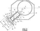
figure 2 est un schéma de principe du dispositif de pompage d'un bloc modulaire de lafigure 1 , - la
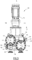
figure 3 est une vue de face d'une pompe électrique comprenant deux blocs modulaires selon un mode de réalisation de l'invention, - la
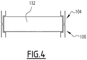
figure 4 est une vue schématique d'un exemple de roulement entre deux blocs modulaires selon l'invention, et - les
figures 5 et6 sont des vues de face d'une pompe électrique comprenant respectivement trois et cinq blocs modulaires selon des variantes de l'invention. - Un bloc modulaire 10 pour pompe électrique pour produit fluide est représenté sur la
figure 1 et visible sur lesfigures 2 à 6 . - Le bloc modulaire 10 comprend un corps principal 12 et un dispositif de pompage 14.
- Le bloc modulaire 10 est prévu pour coopérer avec l'arbre d'un moteur s'étendant selon une direction dite d'élévation Z.
- On définit une direction longitudinale X et une direction transversale Y perpendiculaires entre elles et perpendiculaires à la direction d'élévation Z, de manière à définir un repère orthogonal.
- Le corps principal 12 comprend une ou, ici, des parois latérales extérieures 16.
- Le corps principal 12 comprend en outre une paroi latérale interne 17 et ici une cloison intermédiaire 18.
- Le corps principal 12 présente une forme générale. La forme générale est ici définie par la ou les parois latérales extérieures 16.
- Les parois latérales extérieures 16 s'étendent ici selon la direction d'élévation Z.
- Les parois latérales extérieures 16 présentent une dimension selon la direction d'élévation Z, ladite dimension étant appelée hauteur, constante sur l'ensemble des parois.
- La forme générale présente une symétrie de rotation discrète par rapport à un axe de réversion δ, plus particulièrement pour un angle de rotation sensiblement égal à 180°.
- La forme générale présente une symétrie orthogonale par rapport à un premier plan Ph et par rapport à un deuxième plan Pv.
- Le deuxième plan Pv est perpendiculaire au premier plan Ph.
- L'axe de réversion δ correspond ici à l'intersection du premier plan Ph et du deuxième plan Pv.
- Le premier plan Ph s'étend selon la direction longitudinale X et selon la direction transversale Y.
- Le deuxième plan Pv s'étend selon la direction transversale Y et selon la direction d'élévation Z.
- Pour les besoins de la description, nous considérons que le deuxième plan Pv sépare l'espace en deux moitiés selon un premier côté E1 du deuxième plan et un deuxième côté E2 du deuxième plan. Le deuxième plan Pv est appelé également plan central.
- La paroi latérale interne 17 définit un orifice traversant 20 traversant le bloc modulaire 10.
- L'orifice traversant 20 traverse le bloc modulaire 10 selon la direction d'élévation Z.
- Le corps principal 12 est configuré pour recevoir l'arbre du moteur dans l'orifice traversant 20.
- La paroi latérale interne 17 présente une hauteur constante, plus particulièrement égale à la hauteur des parois latérales extérieures.
- La paroi latérale interne 17 est de niveau avec les parois latérales extérieures 16.
- La paroi latérale interne 17 est inclus dans la forme générale.
- La paroi latérale interne 17 est en contact avec la ou les parois latérales extérieures 16 en un emplacement 21 compris dans le deuxième plan Pv.
- L'orifice traversant 20 présente un axe central D, s'étendant ici selon la direction d'élévation Z.
- L'orifice traversant 20 présente une symétrie orthogonale par rapport au premier plan Ph et par rapport au deuxième plan Pv.
- La paroi latérale interne 17 est ici un cylindre à base circulaire ayant pour axe de révolution l'axe central D de l'orifice traversant 20.
- Le corps principal 12, plus particulièrement la paroi latérale interne 17, présente un alésage 23 à chaque extrémité de l'orifice traversant 20 selon la direction d'élévation Z. L'alésage 23 s'étend ici sur la face de la paroi latérale interne 17 délimitant l'orifice traversant 20.
- La cloison intermédiaire 18 est ici une cloison médiane du corps principal 12, c'est-à-dire qu'elle s'étend à mi-hauteur du corps principal 12 selon la direction d'élévation Z.
- La cloison intermédiaire 18 s'étend ici selon le premier plan Ph.
- La cloison intermédiaire 18 sépare alors le bloc modulaire 10 en deux moitiés 22, ici symétriques orthogonalement.
- Le bloc modulaire 10, plus particulièrement la cloison intermédiaire 18, les parois latérales extérieures 16 et la paroi latérale interne 17, délimite pour chaque moitié 22 un volume ouvert 24. Le volume ouvert 24 est ouvert à l'opposé de la cloison intermédiaire 18 selon la direction d'élévation Z.
- Chaque volume ouvert 24 est adaptable pour former un réservoir de fluide.
- En particulier, chaque volume ouvert 24 présente une ouverture d'aspiration 25 et une ouverture de refoulement 27.
- L'ouverture d'aspiration 25 est située à proximité de la cloison intermédiaire 18, l'ouverture de refoulement 27 étant plus éloignée de la cloison intermédiaire 18 que l'ouverture d'aspiration 25.
- Le bloc modulaire 10 présente en outre une ou des nervures de renforcement 26 et/ou une ou des cloisons radiales 28.
- Chaque nervure de renforcement 26 relie la paroi latérale interne 17 à la cloison intermédiaire 18.
- Chaque cloison radiale 28 relie la ou une des parois latérales extérieures 16 et la paroi latérale interne 17 sur l'ensemble de la hauteur du corps principal 12. La cloison radiale 28 s'étend ainsi de part et d'autre de la cloison intermédiaire 18.
- Alternativement, le corps principal 12 ne comprend pas de cloison intermédiaire 18 telle que décrit précédemment, mais un autre agencement définissant au moins un volume apte à être adapté pour former un réservoir de fluide. Le corps principal 12 comprend, par exemple, un premier demi-fond et un deuxième demi-fond. Le premier demi-fond s'étend à une première extrémité du corps principal selon la direction d'élévation Z dans la première moitié E1 de l'espace. Le deuxième demi-fond s'étend à une deuxième extrémité du corps principal selon la direction d'élévation Z, opposée à la première extrémité, dans la deuxième moitié E2 de l'espace.
- Le corps principal 12 définit en outre un logement 30, le logement étant prévu pour recevoir le dispositif de pompage 14.
- Le logement 30 est agencé entre la paroi latérale interne 17 et la et une ou des parois latérales extérieures 16.
- Le logement 30 s'étend à l'opposé de l'emplacement 21 de contact entre la paroi latérale interne 17 et la ou les parois latérales extérieures 16 selon la direction longitudinale X.
- Le logement 30 s'étend selon un axe principal Δ compris dans le premier plan Ph. Plus particulièrement, le logement 30 présente une extrémité dite proximale au niveau de l'orifice traversant 20 et une extrémité dite distale opposée à l'extrémité proximale selon la direction de l'axe principal Δ.
- L'axe principal Δ du logement 30 au sein du logement 30 s'étend d'un côté du deuxième plan Pv, plus particulièrement sur l'exemple de la
figure 1 du premier côté E1. - L'axe principal Δ du logement 30 au sein du logement 30 s'étend en dehors du deuxième plan Pv, c'est-à-dire que le point formant l'intersection entre l'axe principal Δ et le deuxième plan Pv est situé en dehors du logement.
- L'intersection entre l'axe principal Δ et le deuxième plan Pv est plus particulièrement situé dans l'orifice traversant 20, plus particulièrement au niveau de l'axe central D de l'orifice traversant 20.
- Le logement 30 débouche dans l'orifice traversant 20 d'une part et à l'extérieur du corps principal 12 d'autre part.
- Le logement 30 présente une symétrie orthogonale par rapport au premier plan Ph.
- L'axe principal Δ du logement 30 définit un angle α avec le deuxième plan Pv.
- La distance selon la direction transversale Y de l'axe principal Δ au sein du logement 30 au deuxième plan Pv est strictement croissante depuis l'extrémité proximale vers l'extrémité distale.
- Le logement 30 est ici délimité par un cylindre creux ayant pour axe de rotation l'axe principal Δ.
- Le logement 30 présente un épaulement 32 visible sur la
figure 2 à proximité de l'orifice traversant 20. - Le corps principal 12 dans son ensemble présente une symétrie orthogonale par rapport au premier plan Ph.
- Le corps principal 12 présente une réversibilité par rotation autour de l'axe de réversion δ d'un angle donné appelé ici angle de réversion. L'angle de réversion est égal à 180°. Cela sera décrit plus en détail ci-après en regard du fonctionnement du bloc modulaire.
- Le corps principal 12 présente ici une hauteur h12 égale à 120 millimètres.
- Le corps principal 12 est, par exemple, réalisé en aluminium ou en acier inoxydable.
- Le dispositif de pompage 14 s'étend partiellement dans le logement 30 du corps principal 12.
- Le dispositif de pompage 14 présente une symétrie orthogonale par rapport au premier plan Ph.
- Le dispositif de pompage 14 s'étend en dehors du deuxième plan Pv.
- Dans l'exemple représenté et comme visible sur la
figure 2 , le dispositif de pompage 14 comprend un piston 40 et un diaphragme 42. - Le piston 40 s'étend au moins partiellement dans le logement 30.
- Le diaphragme 42 s'étend en dehors du logement 30 à l'opposé de l'orifice traversant 20.
- Le diaphragme 42 s'étend en dehors de la forme générale du corps principal 12.
- Le dispositif de pompage 14 comprend en outre une chemise 44 dans laquelle se déplace le piston 40 et/ou un organe de rappel 46 du piston 40.
- Le dispositif de pompage 14 comprend par ailleurs un socle 48 pour le diaphragme 42 et/ou une cloison de fermeture 50. Le diaphragme 42 s'étend entre le socle 48 et la cloison de fermeture 50.
- La chemise 44 et, le cas échéant, le socle 48 et la cloison de fermeture 50 sont, par exemple, réalisés en aluminium et/ou en acier inoxydable.
- La chemise 44 s'étend au moins partiellement dans le logement 30.
- La chemise 44 s'étend entre une extrémité proximale du côté de l'orifice traversant 20 et une extrémité distale du côté du diaphragme 42.
- L'extrémité proximale de la chemise 44 est en appui contre l'épaulement 32 du logement 30.
- Dans l'exemple représenté, la chemise 44 s'étend partiellement en dehors du logement 30. Plus particulièrement, l'extrémité distale de la chemise 44 s'étend en dehors du logement 30.
- La chemise 44 délimite un volume interne.
- La chemise 44 est un cylindre creux, l'axe du cylindre étant avantageusement confondu avec l'axe principal Δ.
- Le diamètre externe de la chemise 44 est sensiblement égal au diamètre du cylindre formant le logement 30.
- La chemise 44 forme un revêtement de l'orifice formant le logement 30.
- Le piston s'étend intégralement dans la chemise 44 et au moins partiellement dans le logement 30.
- La chemise 44 coopère avec le piston 40 de sorte que le piston 40 est apte à coulisser dans la chemise 44, la chemise 44 formant le cylindre complémentaire du piston 40.
- Le piston 40 est apte à coulisser en translation dans la chemise 44 dans la direction de l'axe principal Δ.
- Le piston 40 sépare le volume interne de la chemise 44 en une chambre proximale 52 du côté de l'orifice traversant 20 et une chambre distale 54 du côté du diaphragme 42.
- La chambre distale 54 contient un fluide de transmission.
- Le piston 40 est déplaçable en translation entre deux positions extrêmes : une position dite d'aspiration représentée sur la
figure 2 et une position dite d'expulsion. - Le volume de la chambre distale 54 dans la position d'aspiration est strictement supérieure au volume de la chambre distale 54 dans la position d'expulsion d'une cylindrée donnée, par exemple comprise entre 50 cL et 500 cL.
- Dans l'exemple représenté, dans la position d'aspiration visible sur la
figure 2 , le piston 40 affleure sensiblement la chemise 44 du côté de l'orifice traversant 20, plus particulièrement ici est en appui contre un épaulement extrême 55 de la chemise 44. - Dans la position d'expulsion, le piston affleure sensiblement la chemise 44 du côté du diaphragme 42.
- L'organe de rappel 46 du piston 40 est agencé pour rappeler le piston 40 dans la position d'aspiration.
- L'organe de rappel 46 est ici un ressort travaillant en extension.
- L'organe de rappel 46 s'étend entre une surface d'appui 58 du piston 40 et un épaulement 60 formé au niveau de l'extrémité distale de la chemise 44.
- Plus particulièrement, l'épaulement 60 est formé par le socle 48.
- Le socle 48 s'étend de manière contiguë avec la chemise 44 au niveau de l'extrémité distale de ladite chemise 44.
- Le socle 48 présente une surface de support 62 du diaphragme 42.
- La surface de support 62 est agencé sur le socle 48 à l'opposé de la chemise 44 selon la direction de l'axe principal Δ du logement 30.
- La surface de support 62 est incurvé et concave.
- La surface de support 62 présente une symétrie de rotation continue autour de l'axe principal Δ.
- La surface de support 62 présente généralement la forme d'un bol.
- Une partie centrale de la surface de support 62 s'étend contre l'extrémité distale de la chemise 44.
- La surface de support 62 comprend en outre une partie périphérique entourant la partie centrale.
- Le socle 48 présente une pluralité d'ouvertures traversantes 64 entre le volume interne de la chemise 44 et la surface de support 62.
- La partie périphérique de la surface de support 62 est dépourvue d'ouverture. Le socle 48 est ici fixé sur le corps principal 12.
- La cloison de fermeture 50 s'étend face au socle 48 selon l'axe principal Δ. Elle présente une courbure dans le sens inverse du socle.
- Le socle 48 et la cloison de fermeture 50 délimitent entre eux un volume, présentant ici la forme d'un fuseau.
- La cloison de fermeture 50 présente deux ouvertures 65 dites de connexion permettant l'entrée et/ou la sortie de fluide à travers la cloison de fermeture. Plus particulièrement, une des ouvertures dite ouverture d'entrée permet l'entrée de fluide alors que l'autre des ouvertures dite ouverture de sortie permet la sortie de fluide.
- La cloison de fermeture 50 en dehors des ouvertures de connexion 65 présente une symétrie de rotation continue autour de l'axe principal Δ.
- Chaque ouverture 65 s'étend ici parallèlement au premier plan Ph.
- Chaque ouverture 65 s'étend ici parallèlement au deuxième plan Pv. Plus particulièrement, chaque ouverture 65 définit un angle β avec l'axe principal Δ du logement 30, ledit angle β étant supplémentaire de l'angle α définit entre l'axe principal Δ du logement 30 et le deuxième plan Pv.
- Cela permet notamment de raccorder des tuyaux s'étendant selon la direction longitudinale X sans nécessiter de pièce supplémentaire en coude, de faciliter l'opération du système de tuyauterie pour un opérateur, et de limiter l'encombrement du bloc modulaire avec son système de tuyauterie selon l'axe transversale Y.
- Chaque ouverture de connexion 65 présente un système à clapet (non visible) pour pouvoir réguler respectivement l'entrée ou la sortie de fluide à travers l'ouverture.
- Chaque système à clapet est apte à obturer l'ouverture dans une position d'obturation.
- Chaque système à clapet comprend un système de rappel du clapet dans la position d'obturation. Le système de rappel est, par exemple, mécanique à l'aide d'un ressort et/ou magnétique et/ou électromagnétique.
- Le système à clapet est apte à permettre le passage de fluide à travers l'ouverture dans le sens désiré lorsqu'une force de pression correspondant au sens désiré et supérieure à une force donnée est établi sur le système de clapet.
- De manière avantageuse, un tel système de clapet comprenant un système de rappel ne nécessite pas d'orientation particulière, celui-ci ne fonctionnant pas notamment par gravité.
- Le diaphragme 42 s'étend entre le socle 48 et la cloison de fermeture 50, plus particulièrement dans le volume délimité entre le socle 48 et la cloison de fermeture 50.
- Le diaphragme 42 est fixé sur sa périphérie à la partie périphérique du socle 48 et à la partie périphérique de la cloison de fermeture 50.
- Le diaphragme 42, ainsi que le socle 48 et la cloison de fermeture 50, s'étendent du premier côté E1 du deuxième plan en dehors du deuxième plan Pv.
- Le diaphragme 42 est hermétique.
- Il sépare hermétiquement l'espace entre le socle 48 et la cloison de fermeture 50 entre un volume communicant 66 fluidiquement avec la chambre distale 54 et un volume extérieur 68.
- Les ouvertures de connexion 65 communiquent fluidiquement avec le volume extérieur 68.
- Le diaphragme 42 est apte à se déformer sous une différence de pression entre le volume communiquant 66 et le volume extérieur 68.
- Lorsque la pression du volume communiquant 66 est égale au volume extérieur 68 dit cas iso-pression, le diaphragme s'étend par exemple sensiblement selon un plan parallèle à la direction d'élévation Z.
- Lorsque le piston 40 est dans la position d'aspiration, la pression dans la chambre distale diminue et le diaphragme se déforme de sorte que le volume communiquant 66 diminue et que le volume extérieur 68 augmente par rapport au cas iso-pression.
- Les systèmes de clapet obturant par défaut les ouvertures de connexion, la pression du volume extérieur 68 diminue. Cela entraîne l'ouverture du système de clapet de l'ouverture d'entrée et du fluide pénètre dans le volume extérieur 68.
- Lorsque le piston 40 est dans la position d'expulsion, la pression dans la chambre distale augmente et le diaphragme se déforme de sorte que le volume communiquant 66 augmente et que le volume extérieur 68 diminue par rapport au cas iso-pression.
- Les systèmes de clapet obturant par défaut les ouvertures de connexion, la pression du volume extérieur 68 augmente. Cela entraîne l'ouverture du système de clapet de l'ouverture de sortie s'ouvre et du fluide est expulsé depuis le volume extérieur 68.
- Le diaphragme 42 présente une dimension selon la direction d'élévation Z strictement supérieur à celle du corps principal 12.
- Le diaphragme 42 non déformé est ici un disque d'axe central l'axe principal Δ.
- Le diaphragme 42 présente ici un diamètre D42 strictement supérieur à 120 millimètres, plus particulièrement supérieur ou égal à 250 millimètres.
- Le diaphragme 42 présente en outre un diamètre dit mouillé DM 42 supérieur ou égal à 100 millimètres, plus particulièrement supérieure ou égal à 150 millimètres. On entend par « diamètre mouillé » le diamètre du diaphragme en contact avec le volume communicant 66 et le volume extérieur 68. Le diamètre mouillé correspond au diamètre de la surface du diaphragme se déformant.
- L'angle α entre l'axe principal Δ du logement et le deuxième plan Pv est choisi tel que le diaphragme s'étende entièrement en dehors du deuxième plan Pv. En particulier, l'angle α dépend notamment du diamètre du diaphragme et de la distance du diaphragme à l'orifice traversant 20.
- L'angle α est, par exemple, supérieure ou égale à 20°.
- Le fait que le diaphragme 42 s'étende en dehors de la forme générale du corps principal 12 permet ainsi de réduire la dimension selon la direction d'élévation Z du corps principal 12 à une dimension plus faible que si le diaphragme 42 s'étendait à l'intérieur du corps principal 12.
- Chaque bloc modulaire présente une réversibilité par rotation autour de l'axe de réversion δ, c'est-à-dire que le bloc modulaire est susceptible d'être utilisé dans une première configuration et dans une deuxième configuration, le bloc modulaire ayant subi une rotation d'un angle donné autour de l'axe de réversion δ entre la première configuration et la deuxième configuration. L'angle donné dit de réversion est ici égal à 180°. Plus particulièrement ici, il suffit de changer le système de tuyauterie et de raccordement au bloc modulaire pour rendre utilisable le bloc modulaire dans l'une ou l'autre des configurations.
- Chaque partie fonctionnelle du bloc modulaire est soit commune et utilisable dans les deux configurations, comme le dispositif de pompage, soit est présent en double, comme, dans le cas représenté, le volume ouvert avec les ouvertures correspondantes.
- En particulier, le corps principal 12, le socle 48 pour le diaphragme 42 et la cloison de fermeture 50 sont réversibles par rapport à l'axe de réversion δ.
- Un exemple de procédé de fabrication d'un bloc modulaire va maintenant être décrit en regard des
figures 1 et2 . - Le procédé de fabrication comprend les étapes suivantes :
- fourniture, par exemple par usinage ou extrusion, d'un corps principal 12 tel que décrit précédemment, et
- mise en place d'un dispositif de pompage 14 dans le logement 30 du corps principal.
- Le dispositif de pompage est désaxé par rapport au deuxième plan Pv du corps principal.
- Un exemple de pompe électrique 100 pour produit fluide selon l'invention va maintenant être décrite en regard de la
figure 3 . - La pompe est dimensionnée pour fonctionner jusqu'à une pression de 30 bars.
- La pompe 100 comprend un moteur électrique 102 et au moins deux blocs modulaires 104, 106 tels que décrits précédemment.
- Plus particulièrement ici, la pompe 100 comprend deux blocs modulaires 104, 106.
- Les blocs modulaires 104, 106 sont identiques, c'est-à-dire qu'ils sont formés sur le même modèle avec les mêmes dimensions.
- Ils sont superposés de sorte que leurs formes générales se superposent selon leurs directions d'élévation respectives Z.
- Les directions d'élévation respectives Z des différents blocs modulaires sont confondues.
- Les parois latérales extérieures et internes des différents blocs modulaires sont alignées selon la direction d'élévation Z.
- La direction d'élévation Z est, dans l'exemple représenté, sensiblement parallèle à la direction de la gravité locale.
- Alternativement, la direction d'élévation Z est, par exemple, perpendiculaire à la direction de la gravité locale. Des joints sont avantageusement prévus entre les blocs modulaires.
- Les deuxièmes plans respectifs des blocs modulaires 104, 106 se confondent en un deuxième plan commun Pv.
- Les premiers plans respectifs des blocs modulaires 104, 106 sont parallèles entre eux.
- Les axes principaux respectifs Δ1, Δ2 des blocs modulaires 104, 106 au sein des logements respectifs sont placés alternativement d'un premier côté 108 et d'un deuxième côté 110 du deuxième plan commun Pv.
- Plus particulièrement ici, l'axe principal Δ1 d'un premier bloc modulaire 104 dans le logement correspondant est placé du premier côté 108 du deuxième plan Pv. et l'axe principal Δ2 du deuxième bloc modulaire 106 dans le logement correspondant est placé du deuxième côté 110 du deuxième plan Pv.
- Les diaphragmes des dispositifs de pompage respectifs des blocs modulaires 104, 106 sont placés de manière alternée du premier côté 108 ou du deuxième côté 110 du deuxième plan commun Pv.
- Les diaphragmes sont agencés en quinconce de part et d'autre du deuxième plan commun Pv.
- Chaque bloc modulaire est retourné par rapport au(x) bloc(s) modulaire(s) adjacent(s) selon l'axe de réversion δ correspondant.
- Chaque bloc modulaire est adapté pour fonctionner selon son agencement au sein de la pompe.
- Plus particulièrement, chaque bloc modulaire est apte à être raccordé au niveau des ouvertures de connexion à un circuit de circulation de produit fluide.
- Les différents connectiques et tuyaux raccordés à chaque bloc modulaire sont adaptés pour l'agencement donné.
- Pour chaque bloc modulaire, les systèmes de clapet des ouvertures de connexion sont agencés pour que l'ouverture inférieure 112, 114 selon la direction d'élévation Z soit l'ouverture d'entrée et que l'ouverture supérieure 116, 118 soit l'ouverture de sortie.
- Cela permet avantageusement de chasser de l'air qui serait présent dans le volume extérieur dudit bloc modulaire et susceptible de diminuer l'efficacité de pompage du dispositif de pompage.
- Pour chaque bloc modulaire correspondant à l'exemple décrit en regard de la
figure 1 , le volume ouvert de la moitié situé au-dessus de la cloison intermédiaire selon la direction d'élévation Z fait ici office de réservoir de base et est relié au volume communiquant. Le volume ouvert de la moitié supérieure contient par exemple le même fluide de transmission contenu dans le volume communiquant, de sorte à pouvoir fournir du fluide au volume communiquant d'une part et à permettre l'expulsion du fluide du volume communiquant. - L'ouverture d'aspiration et l'ouverture de refoulement du volume ouvert correspondant sont reliées au volume communiquant par l'intermédiaire de connectiques et tuyaux. L'ouverture d'aspiration et l'ouverture de refoulement de l'autre volume ouvert sont bouchées.
- Plus particulièrement, la pompe comprend ici, pour chaque bloc modulaire, un raccord d'aspiration 120, 122 comprenant un orifice et un bouchon, l'orifice étant prévu pour être placé face à l'ouverture d'aspiration du réservoir et le bouchon face à l'ouverture d'aspiration de l'autre volume ouvert.
- La pompe comprend en outre, pour chaque bloc modulaire, un raccord de refoulement 124, 126 relié à l'ouverture de refoulement du réservoir et un bouchon 128, 130 prévu pour obturer l'ouverture de refoulement de l'autre volume ouvert.
- Comme décrit précédemment, alternativement, un ou des réservoirs sont formés d'un volume agencé différemment que dans l'exemple représenté. Lorsque chaque bloc modulaire comprend deux demi-fonds comme décrit précédemment, le réservoir s'étend, par exemple, sur la hauteur de deux blocs modulaires sur la moitié de chaque bloc, des ouvertures d'aspiration et de refoulement étant prévues sur chaque moitié.
- Chaque réservoir présente, par exemple, un volume supérieure ou égale au volume maximale de fluide de transmission pour remplir l'ensemble de l'espace contenant du fluide de transmission, tel que le volume communiquant et la cylindrée.
- Le ou l'ensemble des réservoirs présente une réversibilité par rotation autour de l'axe de réversion δ de l'angle de réversion.
- La pompe 100 comprend en outre un roulement 132 à chaque interface entre deux blocs modulaires adjacents 104, 106 comme représenté à la
figure 4 . - Le roulement 132 s'étend à cheval sur les deux blocs modulaires.
- L'alésage de chaque bloc modulaire à une extrémité de l'orifice traversant est complémentaire de la moitié du roulement, le roulement étant agencé dans un alésage de chacun des blocs modulaires à l'interface.
- La pompe 100 comprend en outre une plaque inférieure 134 et une plaque supérieure 136, agencées de chaque côté de la superposition des blocs modulaires 104, 106 selon la direction d'élévation Z.
- La plaque inférieure 134 et la plaque supérieure 136 présentent une forme générale superposable avec celle des blocs modulaires.
- La plaque inférieure 134 et la plaque supérieure 136 ferment la pompe 100 de part et d'autre des blocs modulaires 104, 106.
- La pompe 100 comprend un arbre (non visible) s'étendant selon la direction d'élévation Z à travers les orifices traversants des blocs modulaires 104, 106 et déplaçable en rotation autour de la direction d'élévation Z par le moteur électrique 102.
- La pompe comprend en outre, pour chaque bloc modulaire, un moyen de transmission du mouvement de rotation de l'arbre en un mouvement de translation au niveau dudit bloc modulaire selon la direction d'élévation.
- Le moyen de transmission comprend, par exemple, un système de bielle et manivelle, une excentrique ou une came.
- Le moyen de transmission est solidaire de l'arbre en rotation autour de la direction d'élévation Z d'une part et prévu pour interagir avec le dispositif de pompage du bloc modulaire d'autre part.
- Plus particulièrement, le moyen de transmission est prévue pour déplacer le piston entre la position d'aspiration et la position d'expulsion puis inversement, par rotation de l'arbre dans un même sens de fonctionnement du moteur.
- Le fonctionnement de la pompe représentée sur la
figure 3 va maintenant être décrit. - L'ouverture d'entrée 112, 114 et l'ouverture de sortie 116, 118 de chaque bloc modulaire 104, 106 sont reliées à un circuit de circulation de produit fluide, l'ouverture de sortie étant prévue pour expulser du produit fluide à un débit donné dans le circuit de circulation et l'ouverture d'entrée pour aspirer le produit fluide.
- Dans un premier mode de réalisation, les blocs modulaires 104, 106 sont reliés à un même circuit de circulation de produit fluide, de manière à multiplier le débit dans le circuit de circulation.
- Dans un deuxième mode de réalisation, les blocs modulaires 104, 106 sont reliés à des circuits de circulation distincts, par exemple contenant des produits fluides différents.
- Alternativement, certains blocs modulaires sont reliés à un même circuit de circulation de produit fluide et au moins un des blocs modulaires est relié à un circuit de circulation distinct.
- Le moteur électrique 102 entraîne en rotation l'arbre de la pompe autour de la direction d'élévation Z, plus particulièrement selon une vitesse de rotation constante.
- Le piston de chaque bloc modulaire est déplacé via le moyen de transmission entre la position d'aspiration et la position d'expulsion puis inversement.
- Comme expliqué précédemment, cela entraîne une aspiration de produit fluide à travers l'ouverture d'entrée puis une expulsion de produit fluide à travers l'ouverture de sortie.
- Pour chaque bloc modulaire, à chaque cycle, la pompe aspire et refoule pour ce bloc modulaire un volume donné de produit fluide, correspondant ici à la cylindrée du dispositif de pompage associé.
- Un deuxième et un troisième exemples de pompe électrique pour produit fluide selon l'invention sont représentés sur les
figures 5 et6 . - Lesdites pompes diffèrent uniquement de la pompe représentée sur la
figure 3 dans le nombre de blocs modulaires, le deuxième exemple présentant trois blocs modulaires et le troisième exemple présentant cinq blocs modulaires. - Les blocs modulaires sont placés similairement à l'exemple de la
figure 3 , c'est-à-dire qu'ils sont superposés de sorte que les axes principaux sont placés alternativement d'un côté ou de l'autre des deuxièmes plans confondus. - L'ajout ou le retrait de blocs modulaires permet d'ajuster la cylindrée de la pompe et ainsi le débit dans un même circuit de circulation de produit en multipliant le débit correspondant à un bloc modulaire.
- Alternativement ou additionnellement, l'ajout de blocs modulaires permet de contrôler le débit de différents produits en changeant le nombre de circuits de circulation de différents produits auxquels est reliée la pompe.
- Une telle pompe est donc facilement adaptable à différentes gammes de débit par ajout ou retrait de blocs modulaires, sans nécessiter de changement du moteur.
- En outre, l'utilisation de blocs modulaires identiques entre eux réduit le nombre de modèles de pièces nécessaires pour réaliser une pompe. Cela permet de réduire les coûts associés à la fabrication d'une telle pompe.
- En outre, une telle pompe présente un encombrement réduit au sol du fait de l'empilement des blocs modulaires selon la direction d'élévation Z.
- Une telle pompe présente en outre un encombrement réduit selon la direction d'élévation Z du fait que les dispositifs de pompage sont disposés alternativement d'un côté ou de l'autre du deuxième plan, ce qui est notamment permis grâce à la symétrie orthogonale par rapport à leur premier plan respectif de chaque bloc modulaire.
- Le diaphragme présente ici un encombrement important selon la direction d'élévation Z. En effet, plus le piston du dispositif de pompage présente une cylindrée importante, plus la course au centre du diaphragme est élevée à chaque cycle à diamètre égal du diaphragme, ce qui entraîne une usure du diaphragme. Pour limiter l'usure du diaphragme, il est avantageux de diminuer le rapport entre la course au centre du diaphragme sur le diamètre mouillé du diaphragme.
- Pour limiter la course au centre du diaphragme, un diaphragme à grand diamètre est utilisé. Ainsi pour une cylindrée donnée, c'est-à-dire un volume déplacé donné, la course au centre est strictement inférieure pour un diaphragme de diamètre supérieur. On entend ici par « diaphragme à grand diamètre » un diaphragme présentant un diamètre dit mouillé supérieur ou égal à 100 mm.
- L'alternance de côté des diaphragmes permet d'avoir un corps principal pour chaque bloc modulaire présentant une dimension selon la direction d'élévation Z strictement inférieure à celle du diaphragme correspondant.
- Plus particulièrement, la dimension selon la direction d'élévation Z du corps principal est égale au diamètre externe du diaphragme divisée par 2 augmenté d'un jeu de superposition des diaphragmes d'un côté. Le jeu est, par exemple, compris entre un millimètre et dix millimètres.
- La superposition de trois blocs modulaires selon l'invention a ainsi sensiblement le même encombrement selon la direction d'élévation Z que la superposition de deux blocs modulaires dans lesquels les dispositifs de pompage sont superposés.
- Similairement, la superposition de cinq blocs modulaires selon l'invention a sensiblement le même encombrement selon la direction d'élévation Z que la superposition de trois blocs modulaires dans lesquels les dispositifs de pompage sont superposés.
- L'invention a été décrite et représentée dans le cadre d'un dispositif de pompage comprenant un diaphragme. Cependant, l'invention est adaptable à un bloc modulaire comprenant un dispositif de pompage différent, notamment comprenant un piston et dépourvu d'un diaphragme.
- Un tel bloc modulaire ne délimite, par exemple, pas de volume apte à être utilisé comme un réservoir de fluide de transmission.
- Cela permet notamment de pouvoir réaliser le corps principal avec une dimension selon la direction d'élévation Z strictement inférieure à celle du dispositif de pompage, peu importe la nature du dispositif de pompage.
- Chaque corps principal présente ainsi une dimension réduite selon la direction d'élévation Z par rapport au cas où le corps principal est dimensionné tel que les dispositifs de pompage soient superposés les uns sur les autres.
- La superposition des blocs modulaires les uns sur les autres présentent alors un encombrement réduit selon la direction d'élévation Z.
Claims (11)
- Bloc modulaire (10 ; 104, 106) pour pompe électrique (100) pour produit fluide, comprenant :- un corps principal (12) définissant un logement (30) s'étendant selon un axe principal (Δ), le corps principal (12) présentant une forme générale présentant une symétrie de rotation discrète par rapport à un axe de réversion (δ), l'axe principal (Δ) du logement (30) au sein du logement (30) s'étendant d'un premier côté d'un plan central (Pv) en dehors du plan central (Pv), l'axe de réversion (δ) étant inclus dans le plan central (Pv),- un dispositif de pompage (14) s'étendant au moins partiellement dans le logement (30) du corps principal (12).
- Bloc modulaire selon la revendication 1, dans lequel le corps principal (12) délimite au moins un réservoir (24) de fluide, l'au moins un réservoir (24) présentant une réversibilité par rotation par rapport à l'axe de réversion.
- Bloc modulaire selon la revendication 2, dans lequel le corps principal (12) comprend une cloison intermédiaire (18), la cloison intermédiaire (18) délimitant deux volumes ouverts formant les réservoirs (24), chaque volume ouvert présentant un orifice d'aspiration (25) et un orifice de refoulement (27).
- Bloc modulaire selon l'une quelconque des revendications 1 à 3, dans lequel le dispositif de pompage (14) comprend un diaphragme (42), le diaphragme (42) s'étendant du premier côté du plan central (Pv) en dehors du plan central (Pv).
- Bloc modulaire selon la revendication 4, dans lequel le dispositif de pompage (14) comprend un piston (40), le piston (40) s'étendant au moins partiellement dans le logement (30) et étant apte à coulisser selon l'axe principal (Δ) du logement (30).
- Bloc modulaire selon l'une quelconque des revendications 1 à 5, dans lequel la forme générale du corps principal (12) présente une symétrie orthogonale par rapport au plan central (Pv).
- Bloc modulaire selon l'une quelconque des revendications 1 à 6, dans lequel l'axe principal (Δ) s'étend dans un premier plan (Ph), le premier plan (Ph) étant perpendiculaire au plan central (Pv), l'axe de réversion (δ) étant inclus dans le premier plan (Ph).
- Bloc modulaire selon la revendication 7, dans lequel le corps principal (12) délimite un orifice traversant (20) selon une direction perpendiculaire au premier plan (Ph), dite direction d'élévation (Z), l'orifice traversant (20) présentant une symétrie orthogonale par rapport au premier plan (Ph) et par rapport au plan central (Pv), le logement (30) débouchant dans l'orifice traversant (20).
- Bloc modulaire selon les revendications 4 et 8, dans lequel le diaphragme (42) s'étend en dehors du logement (30) à l'opposé de l'orifice traversant (20) selon l'axe principal (Δ) du logement (30).
- Bloc modulaire selon la revendication 8 ou 9, dans lequel l'orifice traversant (20) présente un axe central (D) selon la direction d'élévation (Z), l'intersection entre l'axe principal (Δ) et le plan central (Pv) étant incluse dans l'axe central (D).
- Pompe électrique (100) pour produit fluide comprenant un moteur électrique (102) et au moins deux blocs modulaires (104, 106) selon l'une quelconque des revendications 1 à 10, les blocs modulaires (104, 106) étant identiques et placés côte à côte de sorte que leurs formes générales se superposent selon une direction d'élévation (Z), leurs plans centraux respectifs se confondant en un plan central commun (Pv), les blocs modulaires (104, 106) étant placés de sorte que les axes principaux (Δ1, Δ2) sont placés alternativement d'un premier côté (108) et d'un deuxième côté (110) du plan central commun (Pv).
Applications Claiming Priority (1)
| Application Number | Priority Date | Filing Date | Title |
|---|---|---|---|
| FR1909022A FR3099805B1 (fr) | 2019-08-06 | 2019-08-06 | Bloc modulaire pour pompe électrique à encombrement limité et pompe associée |
Publications (1)
| Publication Number | Publication Date |
|---|---|
| EP3772588A1 true EP3772588A1 (fr) | 2021-02-10 |
Family
ID=68807049
Family Applications (1)
| Application Number | Title | Priority Date | Filing Date |
|---|---|---|---|
| EP20189763.4A Pending EP3772588A1 (fr) | 2019-08-06 | 2020-08-06 | Bloc modulaire pour pompe électrique à encombrement limité et pompe associée |
Country Status (7)
| Country | Link |
|---|---|
| US (1) | US11536266B2 (fr) |
| EP (1) | EP3772588A1 (fr) |
| JP (1) | JP7521966B2 (fr) |
| KR (1) | KR102822124B1 (fr) |
| CN (1) | CN112343802B (fr) |
| FR (1) | FR3099805B1 (fr) |
| RU (1) | RU2020126046A (fr) |
Citations (3)
| Publication number | Priority date | Publication date | Assignee | Title |
|---|---|---|---|---|
| FR2503272A1 (fr) * | 1981-03-31 | 1982-10-08 | Joseph Voegele Ag | Pompe a pistons radiaux |
| DE19536696A1 (de) * | 1995-09-30 | 1997-04-03 | Teves Gmbh Alfred | Elektromotor-Pumpen-Aggregat |
| FR3015582A1 (fr) * | 2013-12-23 | 2015-06-26 | Poclain Hydraulics Ind | Machine hydraulique a pistons radiaux presentant un encombrement radial limite |
Family Cites Families (14)
| Publication number | Priority date | Publication date | Assignee | Title |
|---|---|---|---|---|
| US2255852A (en) * | 1940-04-19 | 1941-09-16 | Radial Pump And Compressor Com | Pump assembly |
| US5634777A (en) * | 1990-06-29 | 1997-06-03 | Albertin; Marc S. | Radial piston fluid machine and/or adjustable rotor |
| IL128934A (en) * | 1999-03-11 | 2002-11-10 | Mapple Technology Ltd | Power unit |
| SK13942001A3 (sk) | 1999-04-01 | 2002-11-06 | Peter Robert Raffaele | Hydrodynamické stroje s vratným pohybom |
| US6547537B2 (en) * | 1999-09-14 | 2003-04-15 | Lawrence P. Olson | Air operated radial piston and diaphragm pump system |
| JP3758480B2 (ja) * | 2000-08-25 | 2006-03-22 | 国産電機株式会社 | ダイヤフラムポンプ |
| ITVI20040051A1 (it) * | 2004-03-12 | 2004-06-12 | Gentilin Srl | Compressore volumetrico alternativo |
| US8192173B2 (en) | 2006-09-12 | 2012-06-05 | Spx Corporation | Pressure compensated and constant horsepower pump |
| US9062665B2 (en) * | 2013-01-15 | 2015-06-23 | Husco International, Inc. | Hydraulic piston pump with throttle control |
| WO2015147971A1 (fr) * | 2014-03-27 | 2015-10-01 | Parker-Hannifin Corporation | Compresseur à piston avec cylindre en verre et piston en graphite |
| WO2016161508A1 (fr) * | 2015-04-09 | 2016-10-13 | Froehler Anthony Steven | Système d'entraînement pour pompes d'injection de produits chimiques et compresseurs à air pour instruments |
| DE102015219537A1 (de) * | 2015-10-08 | 2017-04-27 | Robert Bosch Gmbh | Membrandose zum Dämpfen von Druckpulsationen in einem Niederdruckbereich einer Kolbenpumpe |
| US10823160B1 (en) * | 2017-01-12 | 2020-11-03 | Pumptec Inc. | Compact pump with reduced vibration and reduced thermal degradation |
| GB2564409A (en) * | 2017-07-06 | 2019-01-16 | Pendell Michael | Radial piston machine |
-
2019
- 2019-08-06 FR FR1909022A patent/FR3099805B1/fr active Active
-
2020
- 2020-07-31 CN CN202010756383.0A patent/CN112343802B/zh active Active
- 2020-08-04 US US16/985,172 patent/US11536266B2/en active Active
- 2020-08-04 JP JP2020132263A patent/JP7521966B2/ja active Active
- 2020-08-05 KR KR1020200098004A patent/KR102822124B1/ko active Active
- 2020-08-05 RU RU2020126046A patent/RU2020126046A/ru unknown
- 2020-08-06 EP EP20189763.4A patent/EP3772588A1/fr active Pending
Patent Citations (3)
| Publication number | Priority date | Publication date | Assignee | Title |
|---|---|---|---|---|
| FR2503272A1 (fr) * | 1981-03-31 | 1982-10-08 | Joseph Voegele Ag | Pompe a pistons radiaux |
| DE19536696A1 (de) * | 1995-09-30 | 1997-04-03 | Teves Gmbh Alfred | Elektromotor-Pumpen-Aggregat |
| FR3015582A1 (fr) * | 2013-12-23 | 2015-06-26 | Poclain Hydraulics Ind | Machine hydraulique a pistons radiaux presentant un encombrement radial limite |
Also Published As
| Publication number | Publication date |
|---|---|
| CN112343802B (zh) | 2024-11-05 |
| KR102822124B1 (ko) | 2025-06-18 |
| CN112343802A (zh) | 2021-02-09 |
| JP2021025525A (ja) | 2021-02-22 |
| KR20210018129A (ko) | 2021-02-17 |
| US11536266B2 (en) | 2022-12-27 |
| FR3099805A1 (fr) | 2021-02-12 |
| US20210040941A1 (en) | 2021-02-11 |
| RU2020126046A (ru) | 2022-02-07 |
| FR3099805B1 (fr) | 2022-06-03 |
| JP7521966B2 (ja) | 2024-07-24 |
Similar Documents
| Publication | Publication Date | Title |
|---|---|---|
| EP0173601A1 (fr) | Pompe à vide intégralement sèche et étanche à mouvement rectiligne de compression alternative | |
| FR2733280A1 (fr) | Dispositif a pompe a diaphragme | |
| EP3623618B1 (fr) | Pompe avec système de va-et-vient à pignon et crémaillère et utilisation d'une telle pompe | |
| FR3011290A3 (fr) | Pompe a engrenages a deplacement positif | |
| EP1280996B1 (fr) | Pompe de dosage pour produits liquides | |
| FR3099805A1 (fr) | Bloc modulaire pour pompe électrique à encombrement limité et pompe associée | |
| EP3992425B1 (fr) | Pompe modulaire | |
| EP2679818B1 (fr) | Pompe hydraulique a pistons axiaux pouvant fonctionner dans les deux sens de rotation | |
| EP2669516A1 (fr) | Pompe hydraulique à pistons axiaux | |
| EP3161313B1 (fr) | Pompe volumétrique à piston et procédé de contrôle de débit associé | |
| EP2334906B1 (fr) | Machine rotative a losange deformable multifonctions | |
| EP1820969B1 (fr) | Pompe hydraulique, notamment de groupe électro-pompe en particulier pour la direction assistée de véhicule automobile | |
| FR3005106A1 (fr) | Machine volumique rotative a trois pistons | |
| EP2422087B1 (fr) | Pompe volumetrique comprenant un absorbeur de pression | |
| FR2639066A1 (fr) | Pompe doseuse a boisseau | |
| WO2020208618A1 (fr) | Pompe volumetrique avec mécanisme d'entraînement a axe unique | |
| EP0172076A1 (fr) | Dispositif mesureur-doseur volumétrique pour fluides | |
| WO2000050773A2 (fr) | Pompe volumetrique double | |
| FR3015582A1 (fr) | Machine hydraulique a pistons radiaux presentant un encombrement radial limite | |
| FR3003313A1 (fr) | Pompe volumetrique a soufflets | |
| WO2024231634A1 (fr) | Adaptateur de pression ameliore pour systeme hydraulique | |
| EP2776676A1 (fr) | Compresseur ou pompe rotative a palettes semi- spheriques « sans huile « pour comprimer ou pomper les fluides gazeux ou liquides | |
| WO2013083542A2 (fr) | Pompe et turbine à palettes | |
| FR2838166A1 (fr) | Pompe rotative | |
| EP4709982A1 (fr) | Adaptateur de pression ameliore pour systeme hydraulique |
Legal Events
| Date | Code | Title | Description |
|---|---|---|---|
| PUAI | Public reference made under article 153(3) epc to a published international application that has entered the european phase |
Free format text: ORIGINAL CODE: 0009012 |
|
| STAA | Information on the status of an ep patent application or granted ep patent |
Free format text: STATUS: THE APPLICATION HAS BEEN PUBLISHED |
|
| AK | Designated contracting states |
Kind code of ref document: A1 Designated state(s): AL AT BE BG CH CY CZ DE DK EE ES FI FR GB GR HR HU IE IS IT LI LT LU LV MC MK MT NL NO PL PT RO RS SE SI SK SM TR |
|
| AX | Request for extension of the european patent |
Extension state: BA ME |
|
| STAA | Information on the status of an ep patent application or granted ep patent |
Free format text: STATUS: REQUEST FOR EXAMINATION WAS MADE |
|
| 17P | Request for examination filed |
Effective date: 20210712 |
|
| RBV | Designated contracting states (corrected) |
Designated state(s): AL AT BE BG CH CY CZ DE DK EE ES FI FR GB GR HR HU IE IS IT LI LT LU LV MC MK MT NL NO PL PT RO RS SE SI SK SM TR |
|
| STAA | Information on the status of an ep patent application or granted ep patent |
Free format text: STATUS: EXAMINATION IS IN PROGRESS |
|
| 17Q | First examination report despatched |
Effective date: 20221206 |
|
| GRAP | Despatch of communication of intention to grant a patent |
Free format text: ORIGINAL CODE: EPIDOSNIGR1 |
|
| STAA | Information on the status of an ep patent application or granted ep patent |
Free format text: STATUS: GRANT OF PATENT IS INTENDED |
|
| INTG | Intention to grant announced |
Effective date: 20260127 |
|
| GRAJ | Information related to disapproval of communication of intention to grant by the applicant or resumption of examination proceedings by the epo deleted |
Free format text: ORIGINAL CODE: EPIDOSDIGR1 |
|
| STAA | Information on the status of an ep patent application or granted ep patent |
Free format text: STATUS: EXAMINATION IS IN PROGRESS |
|
| GRAP | Despatch of communication of intention to grant a patent |
Free format text: ORIGINAL CODE: EPIDOSNIGR1 |
|
| STAA | Information on the status of an ep patent application or granted ep patent |
Free format text: STATUS: GRANT OF PATENT IS INTENDED |
|
| INTC | Intention to grant announced (deleted) |