EP3772579B1 - Wellenkupplungssystem für gasturbinenmotor - Google Patents
Wellenkupplungssystem für gasturbinenmotor Download PDFInfo
- Publication number
- EP3772579B1 EP3772579B1 EP20190313.5A EP20190313A EP3772579B1 EP 3772579 B1 EP3772579 B1 EP 3772579B1 EP 20190313 A EP20190313 A EP 20190313A EP 3772579 B1 EP3772579 B1 EP 3772579B1
- Authority
- EP
- European Patent Office
- Prior art keywords
- spool
- coupling system
- condition
- gas turbine
- spool coupling
- Prior art date
- Legal status (The legal status is an assumption and is not a legal conclusion. Google has not performed a legal analysis and makes no representation as to the accuracy of the status listed.)
- Active
Links
Images


Classifications
-
- F—MECHANICAL ENGINEERING; LIGHTING; HEATING; WEAPONS; BLASTING
- F02—COMBUSTION ENGINES; HOT-GAS OR COMBUSTION-PRODUCT ENGINE PLANTS
- F02C—GAS-TURBINE PLANTS; AIR INTAKES FOR JET-PROPULSION PLANTS; CONTROLLING FUEL SUPPLY IN AIR-BREATHING JET-PROPULSION PLANTS
- F02C3/00—Gas-turbine plants characterised by the use of combustion products as the working fluid
- F02C3/04—Gas-turbine plants characterised by the use of combustion products as the working fluid having a turbine driving a compressor
- F02C3/107—Gas-turbine plants characterised by the use of combustion products as the working fluid having a turbine driving a compressor with two or more rotors connected by power transmission
- F02C3/113—Gas-turbine plants characterised by the use of combustion products as the working fluid having a turbine driving a compressor with two or more rotors connected by power transmission with variable power transmission between rotors
-
- F—MECHANICAL ENGINEERING; LIGHTING; HEATING; WEAPONS; BLASTING
- F01—MACHINES OR ENGINES IN GENERAL; ENGINE PLANTS IN GENERAL; STEAM ENGINES
- F01D—NON-POSITIVE DISPLACEMENT MACHINES OR ENGINES, e.g. STEAM TURBINES
- F01D15/00—Adaptations of machines or engines for special use; Combinations of engines with devices driven thereby
- F01D15/10—Adaptations for driving, or combinations with, electric generators
-
- F—MECHANICAL ENGINEERING; LIGHTING; HEATING; WEAPONS; BLASTING
- F01—MACHINES OR ENGINES IN GENERAL; ENGINE PLANTS IN GENERAL; STEAM ENGINES
- F01D—NON-POSITIVE DISPLACEMENT MACHINES OR ENGINES, e.g. STEAM TURBINES
- F01D25/00—Component parts, details, or accessories, not provided for in, or of interest apart from, other groups
- F01D25/34—Turning or inching gear
-
- F—MECHANICAL ENGINEERING; LIGHTING; HEATING; WEAPONS; BLASTING
- F02—COMBUSTION ENGINES; HOT-GAS OR COMBUSTION-PRODUCT ENGINE PLANTS
- F02C—GAS-TURBINE PLANTS; AIR INTAKES FOR JET-PROPULSION PLANTS; CONTROLLING FUEL SUPPLY IN AIR-BREATHING JET-PROPULSION PLANTS
- F02C7/00—Features, components parts, details or accessories, not provided for in, or of interest apart form groups F02C1/00 - F02C6/00; Air intakes for jet-propulsion plants
- F02C7/26—Starting; Ignition
- F02C7/268—Starting drives for the rotor, acting directly on the rotor of the gas turbine to be started
- F02C7/275—Mechanical drives
-
- F—MECHANICAL ENGINEERING; LIGHTING; HEATING; WEAPONS; BLASTING
- F02—COMBUSTION ENGINES; HOT-GAS OR COMBUSTION-PRODUCT ENGINE PLANTS
- F02C—GAS-TURBINE PLANTS; AIR INTAKES FOR JET-PROPULSION PLANTS; CONTROLLING FUEL SUPPLY IN AIR-BREATHING JET-PROPULSION PLANTS
- F02C7/00—Features, components parts, details or accessories, not provided for in, or of interest apart form groups F02C1/00 - F02C6/00; Air intakes for jet-propulsion plants
- F02C7/36—Power transmission arrangements between the different shafts of the gas turbine plant, or between the gas-turbine plant and the power user
-
- F—MECHANICAL ENGINEERING; LIGHTING; HEATING; WEAPONS; BLASTING
- F02—COMBUSTION ENGINES; HOT-GAS OR COMBUSTION-PRODUCT ENGINE PLANTS
- F02C—GAS-TURBINE PLANTS; AIR INTAKES FOR JET-PROPULSION PLANTS; CONTROLLING FUEL SUPPLY IN AIR-BREATHING JET-PROPULSION PLANTS
- F02C9/00—Controlling gas-turbine plants; Controlling fuel supply in air- breathing jet-propulsion plants
-
- F—MECHANICAL ENGINEERING; LIGHTING; HEATING; WEAPONS; BLASTING
- F05—INDEXING SCHEMES RELATING TO ENGINES OR PUMPS IN VARIOUS SUBCLASSES OF CLASSES F01-F04
- F05D—INDEXING SCHEME FOR ASPECTS RELATING TO NON-POSITIVE-DISPLACEMENT MACHINES OR ENGINES, GAS-TURBINES OR JET-PROPULSION PLANTS
- F05D2220/00—Application
- F05D2220/30—Application in turbines
- F05D2220/32—Application in turbines in gas turbines
- F05D2220/323—Application in turbines in gas turbines for aircraft propulsion, e.g. jet engines
-
- F—MECHANICAL ENGINEERING; LIGHTING; HEATING; WEAPONS; BLASTING
- F05—INDEXING SCHEMES RELATING TO ENGINES OR PUMPS IN VARIOUS SUBCLASSES OF CLASSES F01-F04
- F05D—INDEXING SCHEME FOR ASPECTS RELATING TO NON-POSITIVE-DISPLACEMENT MACHINES OR ENGINES, GAS-TURBINES OR JET-PROPULSION PLANTS
- F05D2220/00—Application
- F05D2220/70—Application in combination with
- F05D2220/76—Application in combination with an electrical generator
-
- F—MECHANICAL ENGINEERING; LIGHTING; HEATING; WEAPONS; BLASTING
- F05—INDEXING SCHEMES RELATING TO ENGINES OR PUMPS IN VARIOUS SUBCLASSES OF CLASSES F01-F04
- F05D—INDEXING SCHEME FOR ASPECTS RELATING TO NON-POSITIVE-DISPLACEMENT MACHINES OR ENGINES, GAS-TURBINES OR JET-PROPULSION PLANTS
- F05D2260/00—Function
- F05D2260/40—Transmission of power
- F05D2260/403—Transmission of power through the shape of the drive components
- F05D2260/4031—Transmission of power through the shape of the drive components as in toothed gearing
-
- F—MECHANICAL ENGINEERING; LIGHTING; HEATING; WEAPONS; BLASTING
- F05—INDEXING SCHEMES RELATING TO ENGINES OR PUMPS IN VARIOUS SUBCLASSES OF CLASSES F01-F04
- F05D—INDEXING SCHEME FOR ASPECTS RELATING TO NON-POSITIVE-DISPLACEMENT MACHINES OR ENGINES, GAS-TURBINES OR JET-PROPULSION PLANTS
- F05D2270/00—Control
- F05D2270/30—Control parameters, e.g. input parameters
- F05D2270/304—Spool rotational speed
Definitions
- the subject matter disclosed herein generally relates to rotating machinery and, more particularly, to a method and an apparatus for gas turbine engine spool coupling.
- Gas turbine engines of an aircraft can have different starting requirements for ground-based starting and in-flight restarting.
- Ground-based starting is performed at a steady altitude, while in-flight restarting can occur during a change in altitude and speed of the aircraft.
- In-flight starting can use a windmill effect to drive engine spool rotation by decreasing aircraft altitude.
- a windmill envelope defines a range of altitudes and airspeeds where windmill restarting can be effectively performed that minimizes that chances of rotor lock, dual flameout, or other issues.
- EP 2 540 991 discloses a mechanism for turbine engine start using the low speed spool.
- US 4,062,186 discloses an apparatus for windmill starts in gas turbine engines.
- US 2019/218977 discloses a system for low spool power extraction.
- US 2007/277532 discloses a system with an electromagnetic clutch between two spools.
- a system includes a gas turbine engine having a low speed spool and a high speed spool.
- the system also includes a spool coupling system comprising an electro-mechanical actuator and a clutch configured to mechanically link the low speed spool and the high speed spool.
- a controller is operable to determine a mode of operation of the gas turbine engine, monitor for a spool coupling activation condition associated with the mode of operation, and activate the electro-mechanical actuator of the spool coupling system based on the controller detecting the spool coupling activation condition.
- the controller is further operable to deactivate the electro-mechanical actuator of the spool coupling system after disengagement of the clutch to prevent reengagement of the spool coupling system above the spool coupling activation condition, where disengagement of the clutch of the spool coupling system occurs based on the gas turbine engine reaching a disengagement condition.
- the system may include where the mode of operation of the gas turbine engine distinguishing between ground-based operation and flight operation.
- the system may include where the spool coupling activation condition includes detecting a reduction in speed of the low speed spool below an idle condition prior to a windmill condition while the mode of operation is an in-flight mode.
- the system may include where the engagement condition of the spool coupling system includes a gear ratio level of the spool coupling system aligning with a ratio of high speed spool speed to low speed spool speed.
- the system may include where a stabilization condition is reached after engagement of the spool coupling system resulting in fan windmill power being transferred to the high speed spool.
- the system may include where the low speed spool provides power to the high speed spool until the spool coupling system reaches a disengagement condition, and the spool coupling system is deactivated to prevent reengagement of the spool coupling system above the spool coupling activation condition.
- the system may include where the mode of operation of the gas turbine engine is a sub-idle mode that activates, engages, disengages, and deactivates the spool coupling system below an idle level of operation of the gas turbine engine during flight.
- the system may include where the mode of operation of the gas turbine engine is a low spool power-assisted idle that results in the high speed spool at idle when the spool coupling system is engaged.
- the system may include where the spool coupling system includes a variable transmission system with multiple gear ratios and multiple levels of spool power transfer and engagement speeds.
- a method includes determining, by a controller, a mode of operation of a gas turbine engine, the gas turbine engine having a low speed spool and a high speed spool.
- the controller monitors for a spool coupling activation condition associated with the mode of operation.
- An electro-mechanical actuator of the spool coupling system is activated based on the controller detecting the spool coupling activation condition.
- the engagement of a clutch of the spool coupling system and power transfer between the low speed spool and the high speed spool occurs based on activation of the electro-mechanical actuator of the spool coupling system and reaching an engagement condition of the clutch of the spool coupling system.
- the spool coupling system is configured to mechanically link the low speed spool and the high speed spool when the clutch is engaged.
- the method further comprises deactivating the electro-mechanical actuator of the spool coupling system after disengagement of the clutch to prevent reengagement of the spool coupling system above the spool coupling activation condition, wherein disengagement of the clutch of the spool coupling system occurs based on the gas turbine engine reaching a disengagement condition of the clutch.
- a technical effect of the apparatus, systems and methods is achieved by performing gas turbine engine spool coupling.
- FIG. 1 schematically illustrates a gas turbine engine 20.
- the gas turbine engine 20 is disclosed herein as a two-spool turbofan that generally incorporates a fan section 22, a compressor section 24, a combustor section 26 and a turbine section 28.
- the fan section 22 drives air along a bypass flow path B in a bypass duct, while the compressor section 24 drives air along a core flow path C for compression and communication into the combustor section 26 then expansion through the turbine section 28.
- FIG. 1 schematically illustrates a gas turbine engine 20.
- the gas turbine engine 20 is disclosed herein as a two-spool turbofan that generally incorporates a fan section 22, a compressor section 24, a combustor section 26 and a turbine section 28.
- the fan section 22 drives air along a bypass flow path B in a bypass duct
- the compressor section 24 drives air along a core flow path C for compression and communication into the combustor section 26 then expansion through the turbine section 28.
- the exemplary engine 20 generally includes a low speed spool 30 and a high speed spool 32 mounted for rotation about an engine central longitudinal axis A relative to an engine static structure 36 via several bearing systems 38. It should be understood that various bearing systems 38 at various locations may alternatively or additionally be provided, and the location of bearing systems 38 may be varied as appropriate to the application.
- the low speed spool 30 generally includes an inner shaft 40 that interconnects a fan 42, a low pressure compressor 44 and a low pressure turbine 46.
- the high speed spool 32 includes an outer shaft 50 that interconnects a high pressure compressor 52 and high pressure turbine 54.
- a combustor 56 is arranged in exemplary gas turbine 20 between the high pressure compressor 52 and the high pressure turbine 54.
- An engine static structure 36 is arranged generally between the high pressure turbine 54 and the low pressure turbine 46.
- the engine static structure 36 further supports bearing systems 38 in the turbine section 28.
- the inner shaft 40 and the outer shaft 50 are concentric and rotate via bearing systems 38 about the engine central longitudinal axis A which is collinear with their longitudinal axes.
- the core airflow is compressed by the low pressure compressor 44 then the high pressure compressor 52, mixed and burned with fuel in the combustor 56, then expanded over the high pressure turbine 54 and low pressure turbine 46.
- the turbines 46, 54 rotationally drive the respective low speed spool 30 and high speed spool 32 in response to the expansion. It will be appreciated that each of the positions of the fan section 22, compressor section 24, combustor section 26, turbine section 28 may be varied.
- the engine 20 in one example is a high-bypass geared aircraft engine.
- the engine 20 bypass ratio is greater than about six (6), with an example embodiment being greater than about ten (10).
- Some embodiments can include a gear system 48 with an epicyclic gear train, such as a planetary gear system or other gear system, for example, with a gear reduction ratio of greater than about 2.3.
- the low pressure turbine 46 can have a pressure ratio that is greater than about five.
- the engine 20 bypass ratio is greater than about ten (10:1), the fan diameter is significantly larger than that of the low pressure compressor 44, and the low pressure turbine 46 has a pressure ratio that is greater than about five 5:1.
- Low pressure turbine 46 pressure ratio is pressure measured prior to inlet of low pressure turbine 46 as related to the pressure at the outlet of the low pressure turbine 46 prior to an exhaust nozzle. It should be understood, however, that the above parameters are only exemplary of one embodiment of a geared architecture engine and that the present disclosure is applicable to other gas turbine engines including direct drive turbofans.
- the fan section 22 of the engine 20 is designed for a particular flight condition--typically cruise at about 0.8 Mach and about 35,000 feet (10,668 meters).
- 'TSFC' Thrust Specific Fuel Consumption
- Low fan pressure ratio is the pressure ratio across the fan blade alone, without a Fan Exit Guide Vane (“FEGV”) system.
- the gas turbine engine 20 includes a spool coupling system 70 that is configured to mechanically link the low speed spool 30 and the high speed spool 32.
- the spool coupling system 70 can include a gear train 72 and clutch 74 that enable selective engagement and power transfer between the low speed spool 30 and the high speed spool 32.
- the gear train 72 can include a series of gears at a gear ratio, for instance, that is activated below an idle speed of the gas turbine engine 20 that establishes a matching condition between the low speed spool 30 and the high speed spool 32.
- the spool coupling system 70 can be a variable speed transmission that supports a wider range of speeds.
- the clutch 74 can be a unidirectional clutch, such as a sprag.
- a first shaft 76 can link the spool coupling system 70 with the inner shaft 40
- a second shaft 78 can link the spool coupling system 70 with the outer shaft 50.
- linkages and coupling can include intermediate features such as gearboxes that enable power transfer between the inner shaft 40, first shaft 76, gear train 72, clutch 74, second shaft 78, and the outer shaft 50.
- the alignment of the spool coupling system 70 relative to components of the gas turbine engine 20 is depicted schematically for purposes of explanation and is not limiting with respect to sizing, placement, and other such aspects.
- FIG. 1 illustrates one example of the gas turbine engine 20
- any number of spools, inclusion or omission of the gear system 48, and/or other elements and subsystems are contemplated.
- rotor systems described herein can be used in a variety of applications and need not be limited to gas turbine engines for aircraft applications.
- rotor systems can be included in power generation systems, which may be ground-based as a fixed position or mobile system, and other such applications.
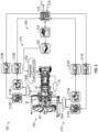
- FIG. 2 illustrates a hybrid electric propulsion system 100 (also referred to as hybrid gas turbine engine 100 or hybrid propulsion system 100) including a gas turbine engine 120 operably coupled to an electrical power system 210 as part of a hybrid electric aircraft.
- One or more mechanical power transmissions 150 can be operably coupled between the gas turbine engine 120 and the electrical power system 210.
- the gas turbine engine 120 can be an embodiment of the gas turbine engine 20 of FIG.
- the electrical power system 210 can include a first electric motor 212A configured to augment rotational power of the low speed spool 30 and a second electric motor 212B configured to augment rotational power of the high speed spool 32. Although two electric motors 212A, 212B are depicted in FIG.
- the electrical power system 210 can also include a first electric generator 213A configured to convert rotational power of the low speed spool 30 to electric power and a second electric generator 213B configured to convert rotational power of the high speed spool 32 to electric power.
- generators 213A, 213B are depicted in FIG. 2 , it will be understood that there may be only a single electric generator (e.g., only electric generator 213A) or additional electric generators (not depicted).
- one or more of the electric motors 212A, 212B can be configured as a motor or a generator depending upon an operational mode or system configuration, and thus one or more of the electric generators 213A, 213B may be omitted.
- the mechanical power transmission 150A includes a gearbox operably coupled between the inner shaft 40 and a combination of the first electric motor 212A and first electric generator 213A.
- the mechanical power transmission 150B can include a gearbox operably coupled between the outer shaft 50 and a combination of the second electric motor 212B and second electric generator 213B.
- the mechanical power transmission 150A, 150B can include a clutch or other interfacing element(s).
- the mechanical power transmission 150A, first electric motor 212A, first electric generator 213A, and associated electronics can be omitted.
- the electrical power system 210 can also include motor drive electronics 214A, 214B operable to condition current to the electric motors 212A, 212B (e.g., DC-to-AC converters).
- the electrical power system 210 can also include rectifier electronics 215A, 215B operable to condition current from the electric generators 213A, 213B (e.g., AC-to-DC converters).
- the motor drive electronics 214A, 214B and rectifier electronics 215A, 215B can interface with an energy storage management system 216 that further interfaces with an energy storage system 218.
- the energy storage management system 216 can be a bi-directional DC-DC converter that regulates voltages between energy storage system 218 and electronics 214A, 214B, 215A, 215B.
- the energy storage system 218 can include one or more energy storage devices, such as a battery, a super capacitor, an ultra capacitor, and the like.
- the energy storage management system 216 can facilitate various power transfers within the hybrid electric propulsion system 100.
- the energy storage management system 216 may also transfer power to one or more electric motors on the engine, or to external loads 217 and receive power from one or more external power sources 219 (e.g., aircraft power, auxiliary power unit power, cross-engine power, and the like).
- external power sources 219 e.g., aircraft power, auxiliary power unit power, cross-engine power, and the like.
- a power conditioning unit 220 and/or other components can be powered by the energy storage system 218.
- the power conditioning unit 220 can distribute electric power to support actuation and other functions of the gas turbine engine 120.
- the power conditioning unit 220 can power an integrated fuel control unit 222 to control fuel flow to the gas turbine engine 120.
- the power conditioning unit 220 can also power a plurality of actuators (not depicted), such as bleed actuators, vane actuators, and the like.
- the spool coupling system 70 can be used to mechanically transfer power between the low speed spool 30 and the high speed spool 32 of the gas turbine engine 120.
- the spool coupling system 70 can be activated and deactivated to operate under selected conditions, such as in support of windmill starting to directly transfer power between the low speed spool 30 and the high speed spool 32.
- the spool coupling system 70 can be activated for transferring power of an electric motor to both spools, such as using the first electric motor 212A for taxiing operations through the low speed spool 30 while also driving the high speed spool 32 to operate accessories and prepare for ground-based starting.
- any effectors that can change a state of the gas turbine engine 120 and/or the electrical power system 210 may be referred to as hybrid electric system control effectors 240.
- Examples of the hybrid electric system control effectors 240 can include the electric motors 212A, 212B, electric generators 213A, 213B, integrated fuel control unit 222, spool coupling system 70, and/or other elements (not depicted).
- FIG. 3 is a schematic diagram of control signal paths 250 of the hybrid electric propulsion system 100 of FIG. 2 and is described with continued reference to FIGS. 1 and 2 .
- a controller 256 can interface with the motor drive electronics 214A, 214B, rectifier electronics 215A, 215B, energy storage management system 216, integrated fuel control unit 222, spool coupling system 70, and/or other components (not depicted) of the hybrid electric propulsion system 100.
- the controller 256 can control and monitor for fault conditions of the gas turbine engine 120 and/or the electrical power system 210.
- the controller 256 can be integrally formed or otherwise in communication with a full authority digital engine control (FADEC) of the gas turbine engine 120.
- FADEC full authority digital engine control
- the controller 256 can include a processing system 260, a memory system 262, and an input/output interface 264.
- the controller 256 can also include various operational controls, such as a spool coupling control 266 that controls the activation/deactivation of the spool coupling system 70 and/or other hybrid electric system control effectors 240 further described herein.
- the processing system 260 can include any type or combination of central processing unit (CPU), including one or more of: a microprocessor, a digital signal processor (DSP), a microcontroller, an application specific integrated circuit (ASIC), a field programmable gate array (FPGA), or the like.
- the memory system 262 can store data and instructions that are executed by the processing system 260.
- the memory system 262 may include random access memory (RAM), read only memory (ROM), or other electronic, optical, magnetic, or any other computer readable medium onto which is stored data and algorithms in a non-transitory form.
- the input/output interface 264 is configured to collect sensor data from the one or more system sensors and interface with various components and subsystems, such as components of the motor drive electronics 214A, 214B, rectifier electronics 215A, 215B, energy storage management system 216, integrated fuel control unit 222, spool coupling system 70, and/or other components (not depicted) of the hybrid electric propulsion system 100.
- the controller 256 provides a means for controlling the hybrid electric system control effectors 240 using a spool coupling control 266 that can be dynamically updated during operation of the hybrid electric propulsion system 100.
- the means for controlling the hybrid electric system control effectors 240 can be otherwise subdivided, distributed, or combined with other control elements.
- the controller 256 with spool coupling control 266 can apply control laws and access/update models to determine how to control and transfer power between the low speed spool 30 and high speed spool 32. For example, sensed and/or derived parameters related to speed, flow rate, pressure ratios, temperature, thrust, and the like can be used to establish operational schedules and transition limits to maintain efficient operation of the gas turbine engine 120. For instance, a mode of operation of the gas turbine engine 120, such as idle, takeoff, climb, cruise, and descent can have different power settings, thrust requirements, flow requirements, and temperature effects.
- the spool coupling control 266 controls an electro-mechanical actuator 79 of the spool coupling system 70 that enables engagement/disengagement of clutch 74 when the electro-mechanical actuator 79 is activated. The spool coupling control 266 can determine when the spool coupling system 70 should be activated to prevent engagement and mechanical linking of the low speed spool 30 and the high speed spool 32 under other conditions where such linkage may be less desirable.
- plot 300 graphically illustrates a relationship between speeds of low speed spool 30 and a high speed spool 32 to support cross-spool coupling in a gas turbine engine, such as the gas turbine engine 20, 120 of FIGS. 1 and 2 .
- ground operation 302 through take-off 303
- in-flight operation 304 plots depict relationships between a speed 310 of the low speed spool 30 and a speed 312 of the high speed spool 32.
- changes in the speed 310 of the low speed spool 30 and the speed 312 of the high speed spool 32 are typically non-linear over a range of operating speeds where the low speed spool 30 and the high speed spool 32 are not mechanically coupled together.
- the ground operation 302 and in-flight operation 304 substantially overlap.
- the in-flight operation 304 can deviate from the ground operation 302 below idle 306 in approaching a windmill condition 308.
- a coupled gear ratio 314 can define a linear relationship between the speed 310 of the low speed spool 30 and the speed 312 of the high speed spool 32 as implemented in the gear train 72 of FIG. 1 .
- the in-flight operation 304 deviates from windmill condition 308 toward a geared windmill condition 318.
- the geared windmill condition 318 has a higher value of speed 312 of the high speed spool 32 at a lower value of speed 310 of the low speed spool 30. This can increase margin against the high speed spool 32 becoming locked at windmill conditions following an engine shutdown.
- the spool coupling system 70 can improve in-flight start capability in windmill conditions and enable more reliable quick-relights.
- the spool coupling system 70 may also improve starter assisted start capability in windmill conditions when used in combination with one or more of the electric motors 212A, 212B, for example.
- plot 400 graphically illustrates a relationship between speeds of low speed spool 30 and a high speed spool 32 to support cross-spool coupling in a gas turbine engine, such as the gas turbine engine 20, 120 of FIGS. 1 and 2 .
- Plot 400 is an example of an in-flight shutdown and restart scenario.
- In-flight operation 404 depicts a relationship between a speed 410 of the low speed spool 30 and a speed 412 of the high speed spool 32.
- Below idle 406 the in-flight operation 404 is non-linear approaching a windmill condition 408.
- a coupled gear ratio 414 can define a linear relationship between the speed 410 of the low speed spool 30 and the speed 412 of the high speed spool 32 as implemented in the gear train 72 of FIG. 1 .
- a spool coupling activation condition 420 can define a threshold for activating or deactivating the spool coupling system 70, where the spool coupling system 70 engages at an engagement condition 430.
- the spool coupling activation condition 420 can be defined below idle 406 and above the engagement condition 430.
- the engagement condition 430 can be an alignment point where the in-flight operation 404 intersects the coupled gear ratio 414 before reaching the windmill condition 408.
- the in-flight operation 404 deviates from windmill condition 408 toward a geared windmill condition 418.
- the geared windmill condition 418 has a higher value of speed 412 of the high speed spool 32 at a lower value of speed 410 of the low speed spool 30.
- the clutch 74 is activated (although not yet engaged) as the low speed spool 30 (or high speed spool 32) transitions below idle 406 while the speed 412 of the high speed spool 32 is still above the level of the coupled gear ratio 414.
- the high speed spool 32 will naturally approach the level of the coupled gear ratio 414 and engage the clutch 74 at which point the low speed spool 30 is transferring power to the high speed spool 32 to maintain the fixed coupled gear ratio of the gear train 72.
- the spool coupling system 70 de-activates to ensure the clutch 74 does not re-engage above idle 406.
- plot 500 graphically illustrates a relationship between speeds of low speed spool 30 and a high speed spool 32 to support cross-spool coupling in a gas turbine engine, such as the gas turbine engine 20, 120 of FIGS. 1 and 2 .
- Plot 500 is an example of low-spool power assisted idle.
- In-flight operation 504 depicts a relationship between a speed 510 of the low speed spool 30 and a speed 512 of the high speed spool 32. Below idle 506, the in-flight operation 504 is non-linear.
- a coupled gear ratio 514 can define a linear relationship between the speed 510 of the low speed spool 30 and the speed 512 of the high speed spool 32 as implemented in the gear train 72 of FIG.
- the engine spools 30, 32 are already at the idle condition, resulting in no delay in achieving idle 506, compared with a restart time if no spool coupling was utilized at low spool power-assisted idle 518.
- the power assist e.g., electric motor 212A
- FIG. 7 is a flow chart illustrating a method 600 for providing selective spool coupling, in accordance with an embodiment.
- the method 600 may be performed, for example, by the gas turbine engine 20 of FIG. 1 , the hybrid electric propulsion system 100 of FIG. 2 , or other such configurations that include the spool coupling system 70.
- the method 600 is described primarily with respect to the hybrid electric propulsion system 100 of FIG. 2 ; however, it will be understood that the method 600 can be performed on other configurations (not depicted).
- Method 600 pertains to the controller 256 executing embedded code for the spool coupling control 266 along with other control functions.
- the controller 256 can determine a mode of operation of a gas turbine engine 120 that includes a low speed spool 30 and a high speed spool 32.
- the mode of operation can be determined based on a thrust command, operating parameters, sensed values, and/or other factors known in the art.
- the mode of operation of the gas turbine engine 120 can distinguish between ground-based operation and flight operation.
- the controller 256 can monitor for a spool coupling activation condition associated with the mode of operation.
- the spool coupling activation condition can include detecting a reduction in speed of the low speed spool 30 below an idle condition prior to a windmill condition while the mode of operation is an in-flight mode.
- the controller 256 can activate a spool coupling system 70 based on the controller 256 detecting the spool coupling activation condition.
- engagement and power transfer between the low speed spool 30 and the high speed spool 32 can occur based on activation of the spool coupling system 70 and reaching an engagement condition of the spool coupling system 70.
- the spool coupling system 70 is configured to mechanically link the low speed spool 30 and the high speed spool 32.
- the engagement condition of the spool coupling system 70 can include a gear ratio level of the spool coupling system 70 aligning with a ratio of high speed spool 32 speed to low speed spool 30 speed.
- a stabilization condition can be reached after engagement of the spool coupling system 70, resulting in fan windmill power being transferred to the high speed spool 32.
- disengagement of the spool coupling system 70 occurs based on the gas turbine engine 20 reaching a disengagement condition.
- the controller 256 can deactivate the spool coupling system 70 to prevent reengagement of the spool coupling system 70 above the spool coupling activation condition.
- the low speed spool 30 can provide power to the high speed spool 32 until the spool coupling system 70 reaches the disengagement condition, and the spool coupling system 70 can be deactivated to prevent reengagement of the spool coupling system 70 above the spool coupling activation condition.
- the mode of operation of the gas turbine engine is a sub-idle mode that activates, engages, disengages, and deactivates the spool coupling system below an idle level of operation of the gas turbine engine during flight.
- the mode of operation of the gas turbine engine 20 can be a low spool power-assisted idle that results in the high speed spool 32 at idle when the spool coupling system 70 is engaged.
- the spool coupling system 70 can include a variable transmission system with multiple gear ratios and multiple levels of spool power transfer and engagement speeds.
Landscapes
- Engineering & Computer Science (AREA)
- Chemical & Material Sciences (AREA)
- Combustion & Propulsion (AREA)
- Mechanical Engineering (AREA)
- General Engineering & Computer Science (AREA)
- Control Of Turbines (AREA)
- Engine Equipment That Uses Special Cycles (AREA)
Claims (11)
- System, umfassend:einen Gasturbinenmotor (20; 120), umfassend eine langsam drehende Welle (30) und eine schnell drehende Welle (32);ein Wellenkupplungssystem (70), umfassend einen elektromechanischen Aktuator (79) und eine Kupplung (74), die zum mechanischen Verbinden der langsam drehenden Welle (30) und der schnell drehenden Welle (32) ausgelegt ist; undeine Steuerung (256), die zu Folgendem betreibbar ist:Bestimmen eines Betriebsmodus des Gasturbinenmotors (20; 120);Überwachen auf einen dem Betriebsmodus zugeordneten Aktivierungszustands der Wellenkupplung;Aktivieren des elektromechanischen Aktuators (79) des Wellenkupplungssystems (70) basierend darauf, dass die Steuerung (256) den Aktivierungszustand der Wellenkupplung erfasst, wobei ein Einrücken der Kupplung (74) und eine Leistungsübertragung zwischen der langsam drehenden Welle (30) und der schnell drehenden Welle (32) basierend auf einer Aktivierung des elektromechanischen Aktuators (79) des Wellenkupplungssystems (70) und einem Erreichen eines Einrückzustands der Kupplung (74) des Wellenkupplungssystems erfolgt; undDeaktivieren des elektromechanischen Aktuators (79) des Wellenkupplungssystems (70) nach Ausrücken der Kupplung (74), um ein erneutes Einrücken des Wellenkupplungssystems über den Aktivierungszustand der Wellenkupplung hinaus zu verhindern, wobei ein Ausrücken der Kupplung des Wellenkupplungssystems (70) basierend darauf erfolgt, dass der Gasturbinenmotor (20; 120) einen Ausrückzustand der Kupplung (74) erreicht.
- System nach Anspruch 1, wobei der Betriebsmodus des Gasturbinenmotors (20; 120) zwischen Bodenbetrieb und Flugbetrieb unterscheidet; und/oderwobei der Betriebsmodus des Gasturbinenmotors (20; 120) ein Unter-Leerlauf-Modus ist, der das Wellenkupplungssystem (70) unterhalb eines Leerlaufbetriebsniveaus des Gasturbinenmotors während eines Fluges aktiviert, einrückt, ausrückt und deaktiviert, oderwobei der Betriebsmodus des Gasturbinenmotors (20; 120) ein Hilfsenergie-Leerlauf mit langsamer Welle ist, der dazu führt, dass sich die schnell drehende Welle (32) im Leerlauf befindet, wenn das Wellenkupplungssystem (70) eingerückt ist.
- System nach einem der vorhergehenden Ansprüche, wobei die Aktivierungsbedingung der Wellenkupplung Erfassen einer Drehzahlverringerung der langsam drehenden Welle (30) unter einen Leerlaufzustand vor einem Zustand mit Antrieb durch Fahrtwind umfasst, während der Betriebsmodus ein Flugmodus ist.
- System nach einem der vorhergehenden Ansprüche, wobei der Einrückzustand des Wellenkupplungssystems (70) ein Übersetzungsverhältnisniveau des Wellenkupplungssystems umfasst, das mit einem Verhältnis von Drehzahl der schnell drehenden Welle zu Drehzahl der langsam drehenden Welle übereinstimmt.
- System nach Anspruch 4, wobei nach dem Einrücken des Wellenkupplungssystems (70) ein Stabilisierungszustand erreicht wird, der dazu führt, dass auf Fahrtwind basierende Leistung des Fans auf die schnell drehende Welle (32) übertragen wird, und wobei die langsam drehende Welle (30) der schnell drehenden Welle (32) Leistung bereitstellt, bis das Wellenkupplungssystem (70) einen Ausrückzustand erreicht, und das Wellenkupplungssystem (70) deaktiviert wird, um ein erneutes Einrücken des Wellenkupplungssystems über den Aktivierungszustand der Wellenkupplung hinaus zu verhindern.
- System nach einem der vorhergehenden Ansprüche, wobei das Wellenkupplungssystem (70) ein variables Getriebesystem mit mehreren Übersetzungsverhältnissen und mehreren Niveaus von Wellenleistungsübertragung und Einrückdrehzahlen umfasst.
- Verfahren, umfassend:Bestimmen (602) eines Betriebsmodus eines Gasturbinenmotors (20; 120) durch eine Steuerung (256), wobei der Gasturbinenmotor eine langsam drehende Welle (30) und eine schnell drehende Welle (32) umfasst;Überwachen (604) auf einen dem Betriebsmodus zugeordneten Aktivierungszustand der Wellenkupplung durch die Steuerung (256);Aktivieren (606) eines elektromechanischen Aktuators (79) eines Wellenkupplungssystems (70) basierend darauf, dass die Steuerung (256) den Aktivierungszustand der Wellenkupplung erfasst, wobei ein Einrücken einer Kupplung (74) des Wellenkupplungssystems (70) und eine Leistungsübertragung (608) zwischen der langsam drehenden Welle (30) und der schnell drehenden Welle (32) basierend auf einer Aktivierung des elektromechanischen Aktuators (79) des Wellenkupplungssystems (70) und einem Erreichen eines Einrückzustands der Kupplung (74) des Wellenkupplungssystems (70) erfolgt, wobei das Wellenkupplungssystem (70) zum mechanischen Verbinden der langsam drehenden Welle (30) und der schnell drehenden Welle (32) bei eingerückter Kupplung ausgelegt ist; undDeaktivieren (612) des elektromechanischen Aktuators (79) des Wellenkupplungssystems (70) nach Ausrücken der Kupplung, um ein erneutes Einrücken des Wellenkupplungssystems über den Aktivierungszustand der Wellenkupplung hinaus zu verhindern, wobei ein Ausrücken (610) der Kupplung des Wellenkupplungssystems (70) basierend darauf erfolgt, dass der Gasturbinenmotor (20; 120) einen Ausrückzustand der Kupplung (74) erreicht.
- Verfahren nach Anspruch 7, wobei der Betriebsmodus des Gasturbinenmotors (20; 120) zwischen Bodenbetrieb und Flugbetrieb unterscheidet; und/oderwobei der Betriebsmodus des Gasturbinenmotors (20; 120) ein Unter-Leerlauf-Modus ist, der das Wellenkupplungssystem (70) unterhalb eines Leerlaufbetriebsniveaus des Gasturbinenmotors während eines Fluges aktiviert, einrückt, ausrückt und deaktiviert, oderwobei der Betriebsmodus des Gasturbinenmotors (20; 120) ein Hilfsenergie-Leerlauf mit langsamer Welle ist, der dazu führt, dass sich die schnell drehende Welle (32) im Leerlauf befindet, wenn das Wellenkupplungssystem (70) eingerückt ist.
- Verfahren nach einem der Ansprüche 7 oder 8, wobei die Aktivierungsbedingung der Wellenkupplung Erfassen einer Drehzahlverringerung der langsam drehenden Welle (30) unter einen Leerlaufzustand vor einem Zustand mit Antrieb durch Fahrtwind umfasst, während der Betriebsmodus ein Flugmodus ist.
- Verfahren nach einem der Ansprüche 7, 8 oder 9, wobei der Einrückzustand des Wellenkupplungssystems (70) ein Übersetzungsverhältnisniveau des Wellenkupplungssystems umfasst, das mit einem Verhältnis von Drehzahl der schnell drehenden Welle zu Drehzahl der langsam drehenden Welle übereinstimmt; und/oder
wobei das Wellenkupplungssystem (70) ein variables Getriebesystem mit mehreren Übersetzungsverhältnissen und mehreren Niveaus von Wellenleistungsübertragung und Einrückdrehzahlen umfasst. - Verfahren nach Anspruch 10, wobei nach dem Einrücken des Wellenkupplungssystems (70) ein Stabilisierungszustand erreicht wird, der dazu führt, dass auf Fahrtwind basierende Leistung des Fans auf die schnell drehende Welle (32) übertragen wird, und wobei die langsam drehende Welle (30) der schnell drehenden Welle (32) Leistung bereitstellt, bis das Wellenkupplungssystem (70) einen Ausrückzustand erreicht, und das Wellenkupplungssystem (70) deaktiviert wird, um ein erneutes Einrücken des Wellenkupplungssystems (70) über den Aktivierungszustand der Wellenkupplung hinaus zu verhindern.
Applications Claiming Priority (1)
| Application Number | Priority Date | Filing Date | Title |
|---|---|---|---|
| US16/536,526 US11459946B2 (en) | 2019-08-09 | 2019-08-09 | Gas turbine engine spool coupling |
Publications (2)
| Publication Number | Publication Date |
|---|---|
| EP3772579A1 EP3772579A1 (de) | 2021-02-10 |
| EP3772579B1 true EP3772579B1 (de) | 2025-06-18 |
Family
ID=72039444
Family Applications (1)
| Application Number | Title | Priority Date | Filing Date |
|---|---|---|---|
| EP20190313.5A Active EP3772579B1 (de) | 2019-08-09 | 2020-08-10 | Wellenkupplungssystem für gasturbinenmotor |
Country Status (2)
| Country | Link |
|---|---|
| US (1) | US11459946B2 (de) |
| EP (1) | EP3772579B1 (de) |
Families Citing this family (3)
| Publication number | Priority date | Publication date | Assignee | Title |
|---|---|---|---|---|
| US12571438B2 (en) | 2021-03-11 | 2026-03-10 | General Electric Company | Turboshaft engine clutch configuration |
| US11988159B2 (en) * | 2021-07-20 | 2024-05-21 | General Electric Company | Electric machine power assist of turbine engine during idle operation |
| CN116592392A (zh) * | 2022-02-07 | 2023-08-15 | 通用电气公司 | 操作具有可变燃烧室的燃烧器的方法 |
Citations (1)
| Publication number | Priority date | Publication date | Assignee | Title |
|---|---|---|---|---|
| US20070277532A1 (en) * | 2006-06-02 | 2007-12-06 | Metin Talan | Two-shaft engine for aircraft with high electric power demand |
Family Cites Families (16)
| Publication number | Priority date | Publication date | Assignee | Title |
|---|---|---|---|---|
| US4062186A (en) | 1976-05-13 | 1977-12-13 | General Electric Company | Apparatus for windmill starts in gas turbine engines |
| US5349814A (en) * | 1993-02-03 | 1994-09-27 | General Electric Company | Air-start assembly and method |
| GB9313905D0 (en) * | 1993-07-06 | 1993-08-25 | Rolls Royce Plc | Shaft power transfer in gas turbine engines |
| US7902999B2 (en) * | 2008-04-18 | 2011-03-08 | Honeywell International Inc. | Gas turbine engine rotor lock prevention system and method |
| US8881534B2 (en) | 2008-12-29 | 2014-11-11 | Rolls-Royce Corporation | Gas turbine engine shaft coupler |
| US8519555B2 (en) * | 2010-11-29 | 2013-08-27 | Pratt & Whitney Canada Corp. | Combination low spool generator and ram air turbine generator |
| US9051881B2 (en) * | 2010-12-28 | 2015-06-09 | Rolls-Royce Corporation | Electrical power generation and windmill starting for turbine engine and aircraft |
| US9200592B2 (en) * | 2011-06-28 | 2015-12-01 | United Technologies Corporation | Mechanism for turbine engine start from low spool |
| WO2014134256A1 (en) | 2013-02-27 | 2014-09-04 | United Technologies Corporation | Low spool starter system for gas turbine engine |
| FR3020838B1 (fr) * | 2014-05-07 | 2019-10-18 | Safran Aircraft Engines | Moteur a turbine a gaz a demarreur en prise avec un corps basse pression |
| US10125692B2 (en) * | 2014-08-22 | 2018-11-13 | Rolls-Royce Corporation | Gas turbine engine system having a disengageable electric machine |
| US10644630B2 (en) * | 2017-11-28 | 2020-05-05 | General Electric Company | Turbomachine with an electric machine assembly and method for operation |
| US10563591B2 (en) | 2018-01-17 | 2020-02-18 | United Technologies Corporation | Systems and methods of low spool power extraction |
| US11333077B2 (en) * | 2019-05-06 | 2022-05-17 | The Boeing Company | Systems and methods for transferring mechanical power in a turbine engine |
| US12092038B2 (en) * | 2019-08-13 | 2024-09-17 | Rtx Corporation | Rotor dynamics accommodation using electrical power assist |
| US20210108569A1 (en) * | 2019-10-15 | 2021-04-15 | General Electric Company | Gas turbine engine with clutch assembly |
-
2019
- 2019-08-09 US US16/536,526 patent/US11459946B2/en active Active
-
2020
- 2020-08-10 EP EP20190313.5A patent/EP3772579B1/de active Active
Patent Citations (1)
| Publication number | Priority date | Publication date | Assignee | Title |
|---|---|---|---|---|
| US20070277532A1 (en) * | 2006-06-02 | 2007-12-06 | Metin Talan | Two-shaft engine for aircraft with high electric power demand |
Also Published As
| Publication number | Publication date |
|---|---|
| US11459946B2 (en) | 2022-10-04 |
| EP3772579A1 (de) | 2021-02-10 |
| US20210040896A1 (en) | 2021-02-11 |
Similar Documents
| Publication | Publication Date | Title |
|---|---|---|
| EP3789603B1 (de) | Elektrische hilfskraftunterstützung für motorneustart im flug | |
| EP3693571B1 (de) | Transiente betriebssteuerung eines hybrid-gasturbinenmotors | |
| EP3770398A1 (de) | Startsteuerung eines hybridgasturbinenmotors | |
| EP3779147B1 (de) | Rotordynamikausgleich unter verwendung von elektrischem hilfsantrieb | |
| EP4352349B1 (de) | Ölzirkulationssystem für hybride elektrische motoren | |
| EP3772579B1 (de) | Wellenkupplungssystem für gasturbinenmotor | |
| EP3865692B1 (de) | Integrierter betrieb von motor und sekundärleistungseinheit | |
| EP4227515B1 (de) | Turbinenmotor mit umgekehrtem brayton-prozess | |
| EP4102044A2 (de) | Elektrische hybridmotorleistungsverteilung | |
| EP3767090B1 (de) | Steuerung der betriebsfähigkeit eines kompressors für einen hybriden elektrischen antrieb | |
| US11821372B2 (en) | Hybrid electric engine with electric tip clearance mechanism | |
| EP4102046A1 (de) | Hybrid-elektrischer leerlaufübergang für flugzeuge | |
| EP4112909A1 (de) | Hybridelektrische turbine mit variabler fläche | |
| EP3767092B1 (de) | Modulierter brennkammer-bypass für hybridleerlauf | |
| EP4407158B1 (de) | Systeme und verfahren zur leistungsregelung mit doppeltwellenkonfiguration | |
| US11557995B2 (en) | Aircraft engine power-assist start stability control | |
| EP3779150B1 (de) | Verbesserung bei der materialermüdung für hybride antriebssysteme |
Legal Events
| Date | Code | Title | Description |
|---|---|---|---|
| PUAI | Public reference made under article 153(3) epc to a published international application that has entered the european phase |
Free format text: ORIGINAL CODE: 0009012 |
|
| STAA | Information on the status of an ep patent application or granted ep patent |
Free format text: STATUS: THE APPLICATION HAS BEEN PUBLISHED |
|
| AK | Designated contracting states |
Kind code of ref document: A1 Designated state(s): AL AT BE BG CH CY CZ DE DK EE ES FI FR GB GR HR HU IE IS IT LI LT LU LV MC MK MT NL NO PL PT RO RS SE SI SK SM TR |
|
| AX | Request for extension of the european patent |
Extension state: BA ME |
|
| STAA | Information on the status of an ep patent application or granted ep patent |
Free format text: STATUS: REQUEST FOR EXAMINATION WAS MADE |
|
| 17P | Request for examination filed |
Effective date: 20210809 |
|
| RBV | Designated contracting states (corrected) |
Designated state(s): AL AT BE BG CH CY CZ DE DK EE ES FI FR GB GR HR HU IE IS IT LI LT LU LV MC MK MT NL NO PL PT RO RS SE SI SK SM TR |
|
| STAA | Information on the status of an ep patent application or granted ep patent |
Free format text: STATUS: EXAMINATION IS IN PROGRESS |
|
| 17Q | First examination report despatched |
Effective date: 20221005 |
|
| RAP3 | Party data changed (applicant data changed or rights of an application transferred) |
Owner name: RTX CORPORATION |
|
| GRAP | Despatch of communication of intention to grant a patent |
Free format text: ORIGINAL CODE: EPIDOSNIGR1 |
|
| STAA | Information on the status of an ep patent application or granted ep patent |
Free format text: STATUS: GRANT OF PATENT IS INTENDED |
|
| INTG | Intention to grant announced |
Effective date: 20250113 |
|
| GRAS | Grant fee paid |
Free format text: ORIGINAL CODE: EPIDOSNIGR3 |
|
| GRAA | (expected) grant |
Free format text: ORIGINAL CODE: 0009210 |
|
| STAA | Information on the status of an ep patent application or granted ep patent |
Free format text: STATUS: THE PATENT HAS BEEN GRANTED |
|
| AK | Designated contracting states |
Kind code of ref document: B1 Designated state(s): AL AT BE BG CH CY CZ DE DK EE ES FI FR GB GR HR HU IE IS IT LI LT LU LV MC MK MT NL NO PL PT RO RS SE SI SK SM TR |
|
| REG | Reference to a national code |
Ref country code: GB Ref legal event code: FG4D |
|
| REG | Reference to a national code |
Ref country code: CH Ref legal event code: EP |
|
| REG | Reference to a national code |
Ref country code: DE Ref legal event code: R096 Ref document number: 602020052836 Country of ref document: DE |
|
| REG | Reference to a national code |
Ref country code: CH Ref legal event code: EP |
|
| REG | Reference to a national code |
Ref country code: IE Ref legal event code: FG4D |
|
| PG25 | Lapsed in a contracting state [announced via postgrant information from national office to epo] |
Ref country code: FI Free format text: LAPSE BECAUSE OF FAILURE TO SUBMIT A TRANSLATION OF THE DESCRIPTION OR TO PAY THE FEE WITHIN THE PRESCRIBED TIME-LIMIT Effective date: 20250618 |
|
| PGFP | Annual fee paid to national office [announced via postgrant information from national office to epo] |
Ref country code: DE Payment date: 20250724 Year of fee payment: 6 |
|
| REG | Reference to a national code |
Ref country code: LT Ref legal event code: MG9D |
|
| PG25 | Lapsed in a contracting state [announced via postgrant information from national office to epo] |
Ref country code: NO Free format text: LAPSE BECAUSE OF FAILURE TO SUBMIT A TRANSLATION OF THE DESCRIPTION OR TO PAY THE FEE WITHIN THE PRESCRIBED TIME-LIMIT Effective date: 20250918 Ref country code: GR Free format text: LAPSE BECAUSE OF FAILURE TO SUBMIT A TRANSLATION OF THE DESCRIPTION OR TO PAY THE FEE WITHIN THE PRESCRIBED TIME-LIMIT Effective date: 20250919 |
|
| PG25 | Lapsed in a contracting state [announced via postgrant information from national office to epo] |
Ref country code: BG Free format text: LAPSE BECAUSE OF FAILURE TO SUBMIT A TRANSLATION OF THE DESCRIPTION OR TO PAY THE FEE WITHIN THE PRESCRIBED TIME-LIMIT Effective date: 20250618 |
|
| PGFP | Annual fee paid to national office [announced via postgrant information from national office to epo] |
Ref country code: GB Payment date: 20250725 Year of fee payment: 6 |
|
| PG25 | Lapsed in a contracting state [announced via postgrant information from national office to epo] |
Ref country code: HR Free format text: LAPSE BECAUSE OF FAILURE TO SUBMIT A TRANSLATION OF THE DESCRIPTION OR TO PAY THE FEE WITHIN THE PRESCRIBED TIME-LIMIT Effective date: 20250618 |
|
| PGFP | Annual fee paid to national office [announced via postgrant information from national office to epo] |
Ref country code: FR Payment date: 20250723 Year of fee payment: 6 |
|
| PG25 | Lapsed in a contracting state [announced via postgrant information from national office to epo] |
Ref country code: RS Free format text: LAPSE BECAUSE OF FAILURE TO SUBMIT A TRANSLATION OF THE DESCRIPTION OR TO PAY THE FEE WITHIN THE PRESCRIBED TIME-LIMIT Effective date: 20250918 |
|
| REG | Reference to a national code |
Ref country code: NL Ref legal event code: MP Effective date: 20250618 |
|
| PG25 | Lapsed in a contracting state [announced via postgrant information from national office to epo] |
Ref country code: LV Free format text: LAPSE BECAUSE OF FAILURE TO SUBMIT A TRANSLATION OF THE DESCRIPTION OR TO PAY THE FEE WITHIN THE PRESCRIBED TIME-LIMIT Effective date: 20250618 |
|
| PG25 | Lapsed in a contracting state [announced via postgrant information from national office to epo] |
Ref country code: NL Free format text: LAPSE BECAUSE OF FAILURE TO SUBMIT A TRANSLATION OF THE DESCRIPTION OR TO PAY THE FEE WITHIN THE PRESCRIBED TIME-LIMIT Effective date: 20250618 |
|
| PG25 | Lapsed in a contracting state [announced via postgrant information from national office to epo] |
Ref country code: PT Free format text: LAPSE BECAUSE OF FAILURE TO SUBMIT A TRANSLATION OF THE DESCRIPTION OR TO PAY THE FEE WITHIN THE PRESCRIBED TIME-LIMIT Effective date: 20251020 |
|
| REG | Reference to a national code |
Ref country code: AT Ref legal event code: MK05 Ref document number: 1804358 Country of ref document: AT Kind code of ref document: T Effective date: 20250618 |
|
| PG25 | Lapsed in a contracting state [announced via postgrant information from national office to epo] |
Ref country code: IS Free format text: LAPSE BECAUSE OF FAILURE TO SUBMIT A TRANSLATION OF THE DESCRIPTION OR TO PAY THE FEE WITHIN THE PRESCRIBED TIME-LIMIT Effective date: 20251018 |
|
| PG25 | Lapsed in a contracting state [announced via postgrant information from national office to epo] |
Ref country code: AT Free format text: LAPSE BECAUSE OF FAILURE TO SUBMIT A TRANSLATION OF THE DESCRIPTION OR TO PAY THE FEE WITHIN THE PRESCRIBED TIME-LIMIT Effective date: 20250618 Ref country code: SM Free format text: LAPSE BECAUSE OF FAILURE TO SUBMIT A TRANSLATION OF THE DESCRIPTION OR TO PAY THE FEE WITHIN THE PRESCRIBED TIME-LIMIT Effective date: 20250618 |
|
| PG25 | Lapsed in a contracting state [announced via postgrant information from national office to epo] |
Ref country code: CZ Free format text: LAPSE BECAUSE OF FAILURE TO SUBMIT A TRANSLATION OF THE DESCRIPTION OR TO PAY THE FEE WITHIN THE PRESCRIBED TIME-LIMIT Effective date: 20250618 |
|
| PG25 | Lapsed in a contracting state [announced via postgrant information from national office to epo] |
Ref country code: PL Free format text: LAPSE BECAUSE OF FAILURE TO SUBMIT A TRANSLATION OF THE DESCRIPTION OR TO PAY THE FEE WITHIN THE PRESCRIBED TIME-LIMIT Effective date: 20250618 |
|
| PG25 | Lapsed in a contracting state [announced via postgrant information from national office to epo] |
Ref country code: EE Free format text: LAPSE BECAUSE OF FAILURE TO SUBMIT A TRANSLATION OF THE DESCRIPTION OR TO PAY THE FEE WITHIN THE PRESCRIBED TIME-LIMIT Effective date: 20250618 |
|
| PG25 | Lapsed in a contracting state [announced via postgrant information from national office to epo] |
Ref country code: RO Free format text: LAPSE BECAUSE OF FAILURE TO SUBMIT A TRANSLATION OF THE DESCRIPTION OR TO PAY THE FEE WITHIN THE PRESCRIBED TIME-LIMIT Effective date: 20250618 Ref country code: SK Free format text: LAPSE BECAUSE OF FAILURE TO SUBMIT A TRANSLATION OF THE DESCRIPTION OR TO PAY THE FEE WITHIN THE PRESCRIBED TIME-LIMIT Effective date: 20250618 |
|
| PG25 | Lapsed in a contracting state [announced via postgrant information from national office to epo] |
Ref country code: ES Free format text: LAPSE BECAUSE OF FAILURE TO SUBMIT A TRANSLATION OF THE DESCRIPTION OR TO PAY THE FEE WITHIN THE PRESCRIBED TIME-LIMIT Effective date: 20250618 |
|
| REG | Reference to a national code |
Ref country code: CH Ref legal event code: H13 Free format text: ST27 STATUS EVENT CODE: U-0-0-H10-H13 (AS PROVIDED BY THE NATIONAL OFFICE) Effective date: 20260324 |
|
| PG25 | Lapsed in a contracting state [announced via postgrant information from national office to epo] |
Ref country code: MC Free format text: LAPSE BECAUSE OF FAILURE TO SUBMIT A TRANSLATION OF THE DESCRIPTION OR TO PAY THE FEE WITHIN THE PRESCRIBED TIME-LIMIT Effective date: 20250618 |
|
| PG25 | Lapsed in a contracting state [announced via postgrant information from national office to epo] |
Ref country code: DK Free format text: LAPSE BECAUSE OF FAILURE TO SUBMIT A TRANSLATION OF THE DESCRIPTION OR TO PAY THE FEE WITHIN THE PRESCRIBED TIME-LIMIT Effective date: 20250618 |
|
| PG25 | Lapsed in a contracting state [announced via postgrant information from national office to epo] |
Ref country code: LU Free format text: LAPSE BECAUSE OF NON-PAYMENT OF DUE FEES Effective date: 20250810 Ref country code: IT Free format text: LAPSE BECAUSE OF FAILURE TO SUBMIT A TRANSLATION OF THE DESCRIPTION OR TO PAY THE FEE WITHIN THE PRESCRIBED TIME-LIMIT Effective date: 20250618 |
|
| PLBE | No opposition filed within time limit |
Free format text: ORIGINAL CODE: 0009261 |
|
| STAA | Information on the status of an ep patent application or granted ep patent |
Free format text: STATUS: NO OPPOSITION FILED WITHIN TIME LIMIT |