EP3772144A1 - Intermediate product and method for crimping an electrical conductor - Google Patents
Intermediate product and method for crimping an electrical conductor Download PDFInfo
- Publication number
- EP3772144A1 EP3772144A1 EP20187316.3A EP20187316A EP3772144A1 EP 3772144 A1 EP3772144 A1 EP 3772144A1 EP 20187316 A EP20187316 A EP 20187316A EP 3772144 A1 EP3772144 A1 EP 3772144A1
- Authority
- EP
- European Patent Office
- Prior art keywords
- region
- electrical conductor
- longitudinal axis
- crimping
- shielding braid
- Prior art date
- Legal status (The legal status is an assumption and is not a legal conclusion. Google has not performed a legal analysis and makes no representation as to the accuracy of the status listed.)
- Pending
Links
- 239000004020 conductor Substances 0.000 title claims abstract description 66
- 238000002788 crimping Methods 0.000 title claims abstract description 25
- 239000013067 intermediate product Substances 0.000 title claims abstract description 17
- 238000000034 method Methods 0.000 title claims abstract description 11
- 238000009413 insulation Methods 0.000 claims abstract description 16
- 238000002604 ultrasonography Methods 0.000 claims description 4
- 238000003466 welding Methods 0.000 claims description 4
- 238000003825 pressing Methods 0.000 claims 1
- 238000004519 manufacturing process Methods 0.000 abstract description 7
- 239000002699 waste material Substances 0.000 description 3
- 230000006835 compression Effects 0.000 description 2
- 238000007906 compression Methods 0.000 description 2
- 230000000694 effects Effects 0.000 description 2
- 239000012774 insulation material Substances 0.000 description 2
- 230000001681 protective effect Effects 0.000 description 2
- 238000011161 development Methods 0.000 description 1
- 230000018109 developmental process Effects 0.000 description 1
- 239000011888 foil Substances 0.000 description 1
- 239000000463 material Substances 0.000 description 1
- 239000000047 product Substances 0.000 description 1
- 230000003068 static effect Effects 0.000 description 1
Images
Classifications
-
- H—ELECTRICITY
- H01—ELECTRIC ELEMENTS
- H01R—ELECTRICALLY-CONDUCTIVE CONNECTIONS; STRUCTURAL ASSOCIATIONS OF A PLURALITY OF MUTUALLY-INSULATED ELECTRICAL CONNECTING ELEMENTS; COUPLING DEVICES; CURRENT COLLECTORS
- H01R43/00—Apparatus or processes specially adapted for manufacturing, assembling, maintaining, or repairing of line connectors or current collectors or for joining electric conductors
- H01R43/28—Apparatus or processes specially adapted for manufacturing, assembling, maintaining, or repairing of line connectors or current collectors or for joining electric conductors for wire processing before connecting to contact members, not provided for in groups H01R43/02 - H01R43/26
-
- H—ELECTRICITY
- H01—ELECTRIC ELEMENTS
- H01R—ELECTRICALLY-CONDUCTIVE CONNECTIONS; STRUCTURAL ASSOCIATIONS OF A PLURALITY OF MUTUALLY-INSULATED ELECTRICAL CONNECTING ELEMENTS; COUPLING DEVICES; CURRENT COLLECTORS
- H01R4/00—Electrically-conductive connections between two or more conductive members in direct contact, i.e. touching one another; Means for effecting or maintaining such contact; Electrically-conductive connections having two or more spaced connecting locations for conductors and using contact members penetrating insulation
- H01R4/10—Electrically-conductive connections between two or more conductive members in direct contact, i.e. touching one another; Means for effecting or maintaining such contact; Electrically-conductive connections having two or more spaced connecting locations for conductors and using contact members penetrating insulation effected solely by twisting, wrapping, bending, crimping, or other permanent deformation
- H01R4/18—Electrically-conductive connections between two or more conductive members in direct contact, i.e. touching one another; Means for effecting or maintaining such contact; Electrically-conductive connections having two or more spaced connecting locations for conductors and using contact members penetrating insulation effected solely by twisting, wrapping, bending, crimping, or other permanent deformation by crimping
- H01R4/20—Electrically-conductive connections between two or more conductive members in direct contact, i.e. touching one another; Means for effecting or maintaining such contact; Electrically-conductive connections having two or more spaced connecting locations for conductors and using contact members penetrating insulation effected solely by twisting, wrapping, bending, crimping, or other permanent deformation by crimping using a crimping sleeve
-
- H—ELECTRICITY
- H01—ELECTRIC ELEMENTS
- H01B—CABLES; CONDUCTORS; INSULATORS; SELECTION OF MATERIALS FOR THEIR CONDUCTIVE, INSULATING OR DIELECTRIC PROPERTIES
- H01B13/00—Apparatus or processes specially adapted for manufacturing conductors or cables
- H01B13/0006—Apparatus or processes specially adapted for manufacturing conductors or cables for reducing the size of conductors or cables
-
- H—ELECTRICITY
- H01—ELECTRIC ELEMENTS
- H01B—CABLES; CONDUCTORS; INSULATORS; SELECTION OF MATERIALS FOR THEIR CONDUCTIVE, INSULATING OR DIELECTRIC PROPERTIES
- H01B11/00—Communication cables or conductors
-
- H—ELECTRICITY
- H01—ELECTRIC ELEMENTS
- H01B—CABLES; CONDUCTORS; INSULATORS; SELECTION OF MATERIALS FOR THEIR CONDUCTIVE, INSULATING OR DIELECTRIC PROPERTIES
- H01B11/00—Communication cables or conductors
- H01B11/02—Cables with twisted pairs or quads
- H01B11/06—Cables with twisted pairs or quads with means for reducing effects of electromagnetic or electrostatic disturbances, e.g. screens
-
- H—ELECTRICITY
- H01—ELECTRIC ELEMENTS
- H01B—CABLES; CONDUCTORS; INSULATORS; SELECTION OF MATERIALS FOR THEIR CONDUCTIVE, INSULATING OR DIELECTRIC PROPERTIES
- H01B13/00—Apparatus or processes specially adapted for manufacturing conductors or cables
- H01B13/0036—Details
-
- H—ELECTRICITY
- H01—ELECTRIC ELEMENTS
- H01B—CABLES; CONDUCTORS; INSULATORS; SELECTION OF MATERIALS FOR THEIR CONDUCTIVE, INSULATING OR DIELECTRIC PROPERTIES
- H01B7/00—Insulated conductors or cables characterised by their form
- H01B7/02—Disposition of insulation
-
- H—ELECTRICITY
- H01—ELECTRIC ELEMENTS
- H01R—ELECTRICALLY-CONDUCTIVE CONNECTIONS; STRUCTURAL ASSOCIATIONS OF A PLURALITY OF MUTUALLY-INSULATED ELECTRICAL CONNECTING ELEMENTS; COUPLING DEVICES; CURRENT COLLECTORS
- H01R13/00—Details of coupling devices of the kinds covered by groups H01R12/70 or H01R24/00 - H01R33/00
- H01R13/648—Protective earth or shield arrangements on coupling devices, e.g. anti-static shielding
- H01R13/658—High frequency shielding arrangements, e.g. against EMI [Electro-Magnetic Interference] or EMP [Electro-Magnetic Pulse]
- H01R13/6591—Specific features or arrangements of connection of shield to conductive members
- H01R13/65912—Specific features or arrangements of connection of shield to conductive members for shielded multiconductor cable
-
- H—ELECTRICITY
- H01—ELECTRIC ELEMENTS
- H01R—ELECTRICALLY-CONDUCTIVE CONNECTIONS; STRUCTURAL ASSOCIATIONS OF A PLURALITY OF MUTUALLY-INSULATED ELECTRICAL CONNECTING ELEMENTS; COUPLING DEVICES; CURRENT COLLECTORS
- H01R43/00—Apparatus or processes specially adapted for manufacturing, assembling, maintaining, or repairing of line connectors or current collectors or for joining electric conductors
- H01R43/02—Apparatus or processes specially adapted for manufacturing, assembling, maintaining, or repairing of line connectors or current collectors or for joining electric conductors for soldered or welded connections
- H01R43/0207—Ultrasonic-, H.F.-, cold- or impact welding
-
- H—ELECTRICITY
- H01—ELECTRIC ELEMENTS
- H01R—ELECTRICALLY-CONDUCTIVE CONNECTIONS; STRUCTURAL ASSOCIATIONS OF A PLURALITY OF MUTUALLY-INSULATED ELECTRICAL CONNECTING ELEMENTS; COUPLING DEVICES; CURRENT COLLECTORS
- H01R43/00—Apparatus or processes specially adapted for manufacturing, assembling, maintaining, or repairing of line connectors or current collectors or for joining electric conductors
- H01R43/04—Apparatus or processes specially adapted for manufacturing, assembling, maintaining, or repairing of line connectors or current collectors or for joining electric conductors for forming connections by deformation, e.g. crimping tool
- H01R43/048—Crimping apparatus or processes
-
- H—ELECTRICITY
- H05—ELECTRIC TECHNIQUES NOT OTHERWISE PROVIDED FOR
- H05K—PRINTED CIRCUITS; CASINGS OR CONSTRUCTIONAL DETAILS OF ELECTRIC APPARATUS; MANUFACTURE OF ASSEMBLAGES OF ELECTRICAL COMPONENTS
- H05K9/00—Screening of apparatus or components against electric or magnetic fields
- H05K9/0073—Shielding materials
- H05K9/0098—Shielding materials for shielding electrical cables
-
- H—ELECTRICITY
- H01—ELECTRIC ELEMENTS
- H01R—ELECTRICALLY-CONDUCTIVE CONNECTIONS; STRUCTURAL ASSOCIATIONS OF A PLURALITY OF MUTUALLY-INSULATED ELECTRICAL CONNECTING ELEMENTS; COUPLING DEVICES; CURRENT COLLECTORS
- H01R9/00—Structural associations of a plurality of mutually-insulated electrical connecting elements, e.g. terminal strips or terminal blocks; Terminals or binding posts mounted upon a base or in a case; Bases therefor
- H01R9/03—Connectors arranged to contact a plurality of the conductors of a multiconductor cable, e.g. tapping connections
- H01R9/05—Connectors arranged to contact a plurality of the conductors of a multiconductor cable, e.g. tapping connections for coaxial cables
- H01R9/0518—Connection to outer conductor by crimping or by crimping ferrule
Definitions
- the invention relates to an intermediate product for crimping and to a method for crimping an electrical conductor.
- contacts with a crimp connection for example a crimp sleeve
- a crimp connection for example a crimp sleeve
- the electrical conductors are manufactured with a certain tolerance, which results in irregularities arising in the diameter of the conductor.
- electrical conductors with slight differences in diameter can be found on the market.
- this leads to waste for example if single strands of a shielding braid protrude radially out of the crimp seam of an e.g. slotted, open crimp sleeve, such that this results in an excessively high degree of waste during production of a crimped conductor.
- the problem of the invention is therefore to provide an intermediate product for crimping, which reduces the risk of manufacturing errors during crimping.
- an intermediate product for crimping having an electrical conductor, in particular a network cable, which extends along a longitudinal axis, having a shielding braid and having an insulation which encloses the shielding braid, wherein the electrical conductor has, in a region along the longitudinal axis, a radially compressed core in comparison to the immediate surroundings along the longitudinal axis.
- a method for crimping an electrical conductor in particular a network cable, which extends along a longitudinal axis, having a shielding braid and an insulation which encloses the electrical conductor, comprising the step of compacting a region of the electrical conductor, which extends along the longitudinal axis, in the radial direction before the crimping.
- a region with a radially compressed core is created by the compacting.
- the compressed core can have a predefined diameter, wherein the irregularities in the diameter of the electrical line are eliminated in the region with the radially compressed core.
- the crimp sleeve can be laid around this region and be crimped with the conductor, without the individual stands projecting radially out of the crimp seam. Consequently, the production of waste product on account of faulty crimping is reduced or even prevented.
- different electrical conductors with slight differences in diameter can be standardised at least in that region, so that structurally identical crimp sleeves can be attached in the regions of the different conductors. As a result, the variety of components is reduced, resulting in further cost savings. Small requirements of a special line can potentially be crimped with existing components, in particular crimp sleeves.
- the region with the radially compressed core can be arranged at a free end of the electrical conductor.
- the crimp sleeve in the region with the radially compressed core can be pushed up slightly and crimped with this region.
- the region with the radially compressed core can be spaced apart from the free end of the electrical conductor along the longitudinal axis, preferably at most by the length of a crimp sleeve which is standardised in particular for network cables having a standardised diameter.
- a crimp sleeve which is standardised in particular for network cables having a standardised diameter.
- the length of the region with the radially compressed core can correspond at least to the length of a crimp sleeve which is standardised for the conductor diameter.
- the region with the radially compressed core offers a seat for the crimp sleeve, wherein, in the region, the diameter of the electrical conductor is predetermined by the compacting.
- the region with the radially compressed core can be arranged at a spacing of approximately 2 mm to approximately 4 mm from the free end in the longitudinal axis.
- the region with the compressed core can taper off conically along the longitudinal axis at one end of the region.
- the region with the compressed core can taper off conically at both ends of the region along the longitudinal axis, with the result that a build-up of the insulation material at both ends of the region, for example as a result of a stepwise decrease in the diameter of the electrical conductor, can be prevented.
- the electrical conductor can be free from the insulation at least at the region with the radially compressed core. Therefore, in this region, the crimp sleeve can be applied to the electrical conductor, in particular to the shielding braid, and crimped therewith.
- the shielding braid can in particular be an outer conductor and be formed from stranded wires, for example, in which the individual wires can be compressed to the most precise and completely monitored final dimensions by the compacting.
- the processed electrical conductors do not have any protruding stranded wires or any burrs, and the crimp sleeve can be crimped around the region with the radially compressed core.
- the region with the radially compressed core can be compacted after the stripping. As a result, it is possible to prevent parts of the insulation from getting caught in the shielding braid during the stripping.
- the region with the radially compressed core can preferably be compacted first, before it is stripped. Therefore the insulation can serve as a protective sheath during the compacting and can prevent individual strands of the shielding braid from being damaged.
- the region with the radially compressed core can be compacted by ultrasound welding, for example.
- an inherently homogeneous core with the smallest possible contact resistance can be created.
- the core can also be compressed by compressing radially to a specified diameter.
- the shielding braid can be bent back around the crimp sleeve from the free end of the electrical conductor which protrudes along the longitudinal axis, wherein the bent-back part does not protrude from the shielding braid along the longitudinal axis over the end of the crimp sleeve facing away from the free end of the electrical conductor.
- the crimp sleeve can in particular be a support sleeve, wherein a predetermined section from the shielding braid is turned over the support sleeve, such that the shielding braid surrounds the support sleeve at least partially radially from the outside.
- the section can be crimped by means of an outer sleeve between the support sleeve and the outer sleeve.
- the inner conductor can be free before the crimping of the outer sleeve and crimped with an inner conductor sleeve.
- the outer sleeve can be configured in such a way that it extends away along the longitudinal axis over the inner conductor sleeve and surrounds it radially.
- the intermediate product 1 comprises an electrical conductor 2, which extends along a longitudinal axis L.
- the electrical conductor 2 can preferably be a standardised network cable 4.
- the electrical conductor 2 has a shielding braid 6 and an insulation 8 radially surrounding the shielding braid 6.
- the electrical conductor 2 is radially compressed to a predetermined diameter 12, so that a crimp sleeve 14 can be placed onto the electrical conductor 2 in this region 10 and can be crimped therewith.
- the conductor By compacting the electrical conductor 2 in the region 10, the conductor can be reduced radially to the predetermined diameter and in particular unified, so that individual strands of the shielding braid 6 do not protrude radially out of the crimp sleeve 14 during crimping.
- At least the region 10 with the radial compression can be free from the insulation 8, as depicted in Fig. 2 , so that the crimp sleeve 14 can be laid directly onto the shielding braid 6.
- the insulation 8 can be removed from the region 10 in particular after the compacting, so that the insulation 8 serves as a protective sheath during the compacting and the individual strands of the shielding braid 6 are not damaged.
- the shielding braid 6 can be compressed to the predefined diameter 12, since the crimp sleeve 14 is laid around the shielding braid 6 during the crimping and is crimped therewith.
- the region 10 can be compressed by ultrasound welding, for example. As an alternative to this or also in addition, the region 10 can also be radially reduced to the predefined diameter 12 by compressing the individual strands.
- the shielding braid 6 can be an outer conductor 16, which is formed from stranded wires 18.
- the adjustment to the predefined diameter 12 can be made more difficult in particular on account of the shielding braid 6.
- irregularities and high tolerances frequently occur during production, which can lead to problems during the crimping, however, since individual strands, in particular stranded wire cores, can protrude radially out of the crimp sleeve 14.
- the electrical conductor 2 can preferably have at least one inner conductor 20, which can be arranged centrally in the electrical conductor 2 and is surrounded radially by a dielectric 22.
- a shielding foil 24 can be arranged between the dielectric 22 and the shielding braid 6 to protect the inner conductor 20 from static magnets and/or magnetic alternating fields.
- the region 10 can be arranged at a free end 24 of the electrical conductor 2 along the longitudinal axis L.
- the region 10 can be spaced apart from a termination 26 at the free end 24 of the electrical conductor 2 along the longitudinal axis L.
- the region 10 can be spaced apart from the termination 26 along the longitudinal axis L, preferably at most by the length of a crimp sleeve 14, in particular a support sleeve 15, which is standardised for network cables.
- the shielding braid 6 can be prevented from protruding from the crimp sleeve 14 when it is turned over the crimp sleeve 14 on the side of the crimp sleeve 14 facing away from the termination 26.
- the length 13 of the region 10 along the longitudinal axis L can preferably correspond at least to the length 17 of a standardised crimp sleeve 14 for network cables.
- a seat can be created for the crimp sleeve 14, which seat prevents the crimp sleeve 14 from sliding along the longitudinal axis L relative to the region 10. This leads to a further facilitation of the crimping procedure.
- the region 10 can taper off conically at at least one end of the region 10 along the longitudinal axis L, in particular at both ends of the region 10.
- a build-up of material during the stripping at the respective ends of the region 10 can be prevented.
- the insulation 8 can be stripped off more easily and a stepwise crossover, in which the insulation 8 can get caught, does not form.
- the free inner conductor 20 can be crimped with an inner conductor sleeve, before an outer sleeve is crimped with the support sleeve 15 and clamps the section of the shielding braid 6, which is turned over the support sleeve 15, between support sleeve 15 and outer sleeve.
- the electrical conductor 2, in particular the shielding braid 6, can be compressed to a substantially uniform and predefined diameter 12 in the region 10 by precompacting, wherein the diameter 12 can be adapted to the respective requirements of the crimp sleeve 14.
- a variety of electrical conductors 2 with small differences in diameter can be standardised at least in the region 10, with the result that different electrical conductors 2 can be coupled to identically structured components, for example crimp sleeves 14. The enables a reduction in different components, resulting in further cost savings.
Landscapes
- Engineering & Computer Science (AREA)
- Manufacturing & Machinery (AREA)
- Microelectronics & Electronic Packaging (AREA)
- Physics & Mathematics (AREA)
- Electromagnetism (AREA)
- Connections Effected By Soldering, Adhesion, Or Permanent Deformation (AREA)
- Manufacturing Of Electrical Connectors (AREA)
Abstract
Description
- The invention relates to an intermediate product for crimping and to a method for crimping an electrical conductor.
- In order to terminate an electrical conductor, contacts with a crimp connection, for example a crimp sleeve, are laid around the electrical conductor and compressed with the crimp connection. As a result, a mechanically and electrically stable connection is produced between the contact and the conductor. The electrical conductors are manufactured with a certain tolerance, which results in irregularities arising in the diameter of the conductor. Furthermore, electrical conductors with slight differences in diameter can be found on the market. In particular in the case of crimping, in practice this leads to waste, for example if single strands of a shielding braid protrude radially out of the crimp seam of an e.g. slotted, open crimp sleeve, such that this results in an excessively high degree of waste during production of a crimped conductor.
- The problem of the invention is therefore to provide an intermediate product for crimping, which reduces the risk of manufacturing errors during crimping.
- The problem is solved according to the invention by an intermediate product for crimping, having an electrical conductor, in particular a network cable, which extends along a longitudinal axis, having a shielding braid and having an insulation which encloses the shielding braid, wherein the electrical conductor has, in a region along the longitudinal axis, a radially compressed core in comparison to the immediate surroundings along the longitudinal axis.
- Furthermore, the problem is solved by a method for crimping an electrical conductor, in particular a network cable, which extends along a longitudinal axis, having a shielding braid and an insulation which encloses the electrical conductor, comprising the step of compacting a region of the electrical conductor, which extends along the longitudinal axis, in the radial direction before the crimping.
- A region with a radially compressed core is created by the compacting. The compressed core can have a predefined diameter, wherein the irregularities in the diameter of the electrical line are eliminated in the region with the radially compressed core. As a result, the crimp sleeve can be laid around this region and be crimped with the conductor, without the individual stands projecting radially out of the crimp seam. Consequently, the production of waste product on account of faulty crimping is reduced or even prevented. Furthermore, different electrical conductors with slight differences in diameter can be standardised at least in that region, so that structurally identical crimp sleeves can be attached in the regions of the different conductors. As a result, the variety of components is reduced, resulting in further cost savings. Small requirements of a special line can potentially be crimped with existing components, in particular crimp sleeves.
- Hereinafter, further developments are specified which can be combined with one another as desired, independently of one another, and are each themselves advantageous per se.
- Thus, for example, the region with the radially compressed core can be arranged at a free end of the electrical conductor. As a result, the crimp sleeve in the region with the radially compressed core can be pushed up slightly and crimped with this region.
- The region with the radially compressed core can be spaced apart from the free end of the electrical conductor along the longitudinal axis, preferably at most by the length of a crimp sleeve which is standardised in particular for network cables having a standardised diameter. As a result, the section of the shielding braid between the region with the radially compressed core and the free end can be bent back over the crimp sleeve, without the shielding braid projecting over the region away along the longitudinal axis.
- According to a further advantageous configuration, the length of the region with the radially compressed core can correspond at least to the length of a crimp sleeve which is standardised for the conductor diameter. Thus the region with the radially compressed core offers a seat for the crimp sleeve, wherein, in the region, the diameter of the electrical conductor is predetermined by the compacting.
- In particular, the region with the radially compressed core can be arranged at a spacing of approximately 2 mm to approximately 4 mm from the free end in the longitudinal axis.
- In a further advantageous configuration, the region with the compressed core can taper off conically along the longitudinal axis at one end of the region. As a result, for example, a build-up of the insulation material at the end of the region along the longitudinal axis can be prevented.
- Preferably, the region with the compressed core can taper off conically at both ends of the region along the longitudinal axis, with the result that a build-up of the insulation material at both ends of the region, for example as a result of a stepwise decrease in the diameter of the electrical conductor, can be prevented.
- According to a further advantageous configuration, the electrical conductor can be free from the insulation at least at the region with the radially compressed core. Therefore, in this region, the crimp sleeve can be applied to the electrical conductor, in particular to the shielding braid, and crimped therewith.
- The shielding braid can in particular be an outer conductor and be formed from stranded wires, for example, in which the individual wires can be compressed to the most precise and completely monitored final dimensions by the compacting. As a result, the processed electrical conductors do not have any protruding stranded wires or any burrs, and the crimp sleeve can be crimped around the region with the radially compressed core.
- The region with the radially compressed core can be compacted after the stripping. As a result, it is possible to prevent parts of the insulation from getting caught in the shielding braid during the stripping. However, the region with the radially compressed core can preferably be compacted first, before it is stripped. Therefore the insulation can serve as a protective sheath during the compacting and can prevent individual strands of the shielding braid from being damaged.
- The region with the radially compressed core can be compacted by ultrasound welding, for example. In particular during the ultrasound welding, an inherently homogeneous core with the smallest possible contact resistance can be created. As an alternative to this, the core can also be compressed by compressing radially to a specified diameter.
- According to a further advantageous configuration, after the crimping of the crimp sleeve in the radially compressed region, the shielding braid can be bent back around the crimp sleeve from the free end of the electrical conductor which protrudes along the longitudinal axis, wherein the bent-back part does not protrude from the shielding braid along the longitudinal axis over the end of the crimp sleeve facing away from the free end of the electrical conductor.
- The crimp sleeve can in particular be a support sleeve, wherein a predetermined section from the shielding braid is turned over the support sleeve, such that the shielding braid surrounds the support sleeve at least partially radially from the outside. The section can be crimped by means of an outer sleeve between the support sleeve and the outer sleeve. Preferably, the inner conductor can be free before the crimping of the outer sleeve and crimped with an inner conductor sleeve. The outer sleeve can be configured in such a way that it extends away along the longitudinal axis over the inner conductor sleeve and surrounds it radially.
- Hereinafter, the invention is described in greater detail by way of example using exemplary embodiments with reference to the attached figures. In the figures, elements which correspond to one another in design and/or function are provided with the same reference numerals.
- The combination of features shown and described with the individual exemplary embodiments serves solely the purposes of explanation. In accordance with the statements above, it is possible to dispense with a feature from an exemplary embodiment if its technical effect is of no importance in a particular application. Conversely, according to the above statements, a further feature can be added to an exemplary embodiment if its technical effect is meant to be advantageous or necessary for a particular application.
- In the figures:
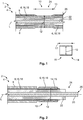
- Fig. 1
- shows a schematic perspective view of an intermediate product according to the invention;
- Fig. 2
- shows a schematic sectional view of the intermediate product depicted in
Fig. 1 after the crimping. - First of all, an exemplary configuration of an
intermediate product 1, according to the invention, for crimping is explained is greater detail with reference toFig. 1 . - The
intermediate product 1 comprises anelectrical conductor 2, which extends along a longitudinal axis L. Theelectrical conductor 2 can preferably be astandardised network cable 4. Theelectrical conductor 2 has a shielding braid 6 and aninsulation 8 radially surrounding the shielding braid 6. In aregion 10 along the longitudinal axis L, theelectrical conductor 2 is radially compressed to apredetermined diameter 12, so that acrimp sleeve 14 can be placed onto theelectrical conductor 2 in thisregion 10 and can be crimped therewith. By compacting theelectrical conductor 2 in theregion 10, the conductor can be reduced radially to the predetermined diameter and in particular unified, so that individual strands of the shielding braid 6 do not protrude radially out of thecrimp sleeve 14 during crimping. - Preferably, at least the
region 10 with the radial compression can be free from theinsulation 8, as depicted inFig. 2 , so that thecrimp sleeve 14 can be laid directly onto the shielding braid 6. Theinsulation 8 can be removed from theregion 10 in particular after the compacting, so that theinsulation 8 serves as a protective sheath during the compacting and the individual strands of the shielding braid 6 are not damaged. - In particular, the shielding braid 6 can be compressed to the
predefined diameter 12, since thecrimp sleeve 14 is laid around the shielding braid 6 during the crimping and is crimped therewith. - The
region 10 can be compressed by ultrasound welding, for example. As an alternative to this or also in addition, theregion 10 can also be radially reduced to thepredefined diameter 12 by compressing the individual strands. - The shielding braid 6 can be an outer conductor 16, which is formed from stranded wires 18. During manufacture of the
electrical conductor 2, the adjustment to thepredefined diameter 12 can be made more difficult in particular on account of the shielding braid 6. In the case of the shielding braid 6, irregularities and high tolerances frequently occur during production, which can lead to problems during the crimping, however, since individual strands, in particular stranded wire cores, can protrude radially out of thecrimp sleeve 14. - The
electrical conductor 2 can preferably have at least oneinner conductor 20, which can be arranged centrally in theelectrical conductor 2 and is surrounded radially by a dielectric 22. A shieldingfoil 24 can be arranged between the dielectric 22 and the shielding braid 6 to protect theinner conductor 20 from static magnets and/or magnetic alternating fields. - The
region 10 can be arranged at afree end 24 of theelectrical conductor 2 along the longitudinal axis L. Preferably theregion 10 can be spaced apart from atermination 26 at thefree end 24 of theelectrical conductor 2 along the longitudinal axis L. Theregion 10 can be spaced apart from thetermination 26 along the longitudinal axis L, preferably at most by the length of acrimp sleeve 14, in particular asupport sleeve 15, which is standardised for network cables. As a result, the shielding braid 6 can be prevented from protruding from thecrimp sleeve 14 when it is turned over thecrimp sleeve 14 on the side of thecrimp sleeve 14 facing away from thetermination 26. - The
length 13 of theregion 10 along the longitudinal axis L can preferably correspond at least to thelength 17 of astandardised crimp sleeve 14 for network cables. As a result of the radial compression in theregion 10, a seat can be created for thecrimp sleeve 14, which seat prevents thecrimp sleeve 14 from sliding along the longitudinal axis L relative to theregion 10. This leads to a further facilitation of the crimping procedure. - Preferably, the
region 10 can taper off conically at at least one end of theregion 10 along the longitudinal axis L, in particular at both ends of theregion 10. As a result, a build-up of material during the stripping at the respective ends of theregion 10 can be prevented. Theinsulation 8 can be stripped off more easily and a stepwise crossover, in which theinsulation 8 can get caught, does not form. - The free
inner conductor 20 can be crimped with an inner conductor sleeve, before an outer sleeve is crimped with thesupport sleeve 15 and clamps the section of the shielding braid 6, which is turned over thesupport sleeve 15, betweensupport sleeve 15 and outer sleeve. - As a result of the intermediate product according to the invention and the method according to the invention, errors during manufacture of crimped
electrical conductors 2 can be reduced or even prevented. Theelectrical conductor 2, in particular the shielding braid 6, can be compressed to a substantially uniform andpredefined diameter 12 in theregion 10 by precompacting, wherein thediameter 12 can be adapted to the respective requirements of thecrimp sleeve 14. Furthermore, as a result of the solution according to the invention, a variety ofelectrical conductors 2 with small differences in diameter can be standardised at least in theregion 10, with the result that differentelectrical conductors 2 can be coupled to identically structured components, for example crimpsleeves 14. The enables a reduction in different components, resulting in further cost savings. -
- 1
- intermediate product
- 2
- electrical conductor
- 4
- network cable
- 6
- shielding braid
- 8
- insulation
- 10
- region
- 12
- predetermined diameter
- 13
- length of the region
- 14
- crimp sleeve
- 15
- support sleeve
- 16
- outer conductor
- 17
- length of a crimp sleeve
- 18
- stranded wires
- 20
- inner conductor
- 22
- dielectric
- 24
- free end
- 26
- termination
Claims (10)
- An intermediate product (1) for crimping, having an electrical conductor (2), in particular having a network cable (4), comprising the electrical conductor (2), which extends along a longitudinal axis (L), having a shielding braid (6) and having an insulation (8) which at least partially encloses the shielding braid (6), wherein the electrical conductor (2) has, in a region (10) along the longitudinal axis (L), a radially compressed core in comparison to the immediate surroundings along the longitudinal axis (L).
- The intermediate product (1) according to Claim 1, wherein the region (10) with the radially compressed core is formed at a free end (24) of the electrical conductor (2).
- The intermediate product (1) according to Claim 1 or 2, wherein the region (10) with the radially compressed core tapers off conically at at least one end of the region (10) along the longitudinal axis (L).
- The intermediate product (1) according to Claim 3, wherein the region (10) with the radially compressed core tapers off conically at both ends of the region (10) along the longitudinal axis (L).
- The intermediate product (1) according to any one of Claims 1 to 4, wherein the shielding braid (6) is free from the insulation (8) at least in the region (10) with the radially compressed core.
- The intermediate product (1) according to any one of Claims 1 to 5, wherein the length of the region (10) with the compressed core corresponds at least to the length of a support sleeve (15) along the longitudinal axis (L), which support sleeve (15) is standardised for a predetermined diameter of an electrical conductor (2).
- A method for crimping an electrical conductor (2), in particular a network cable (4), having a shielding braid (6), which extends along a longitudinal axis (L), and having an insulation (8) which encloses the shielding braid (6), comprising the following step:- compacting a region (10) of the electrical conductor (2), which extends along the longitudinal axis (L), in the radial direction before the crimping.
- The method according to Claim 7, wherein at least the region (10) is stripped after the compacting.
- The method according to Claim 7 or 8, wherein the region (10) is compacted by ultrasound welding.
- The method according to Claim 7 or 8, wherein the region (10) is compacted by pressing.
Applications Claiming Priority (1)
| Application Number | Priority Date | Filing Date | Title |
|---|---|---|---|
| DE102019211473.3A DE102019211473A1 (en) | 2019-07-31 | 2019-07-31 | Intermediate product and process for crimping an electrical conductor |
Publications (1)
| Publication Number | Publication Date |
|---|---|
| EP3772144A1 true EP3772144A1 (en) | 2021-02-03 |
Family
ID=71783856
Family Applications (1)
| Application Number | Title | Priority Date | Filing Date |
|---|---|---|---|
| EP20187316.3A Pending EP3772144A1 (en) | 2019-07-31 | 2020-07-23 | Intermediate product and method for crimping an electrical conductor |
Country Status (5)
| Country | Link |
|---|---|
| US (1) | US10923834B1 (en) |
| EP (1) | EP3772144A1 (en) |
| KR (1) | KR102874849B1 (en) |
| CN (1) | CN112310664B (en) |
| DE (1) | DE102019211473A1 (en) |
Cited By (1)
| Publication number | Priority date | Publication date | Assignee | Title |
|---|---|---|---|---|
| WO2024100589A1 (en) * | 2022-11-11 | 2024-05-16 | Societa' Per Azioni Curti-Costruzioni Meccaniche | Apparatus and process for preparing an end portion of a shielded electric cable |
Families Citing this family (2)
| Publication number | Priority date | Publication date | Assignee | Title |
|---|---|---|---|---|
| DE102021129999A1 (en) * | 2021-11-17 | 2023-05-17 | Te Connectivity Germany Gmbh | Method of crimping an electrical cable and electrical cable |
| DE102024106262A1 (en) * | 2024-03-05 | 2025-09-11 | Md Elektronik Gmbh | METHOD AND DEVICE FOR BRUSHING THE SHIELDING BRAIDED CABLE |
Citations (5)
| Publication number | Priority date | Publication date | Assignee | Title |
|---|---|---|---|---|
| US20110100672A1 (en) * | 2008-04-30 | 2011-05-05 | Md Elektronik Gmbh | Electrical cable and method and device for the manufacture thereof |
| JP2014011133A (en) * | 2012-07-03 | 2014-01-20 | Auto Network Gijutsu Kenkyusho:Kk | Braided wire with terminal fitting and method of manufacturing braided wire with terminal fitting |
| US20150075863A1 (en) * | 2013-09-17 | 2015-03-19 | Sumitomo Wiring Systems, Ltd. | Terminal fitting-equipped conductor |
| EP3179562A1 (en) * | 2015-12-09 | 2017-06-14 | Teleste Oyj | An arrangement for a coaxial cable connector |
| US20190058312A1 (en) * | 2017-08-15 | 2019-02-21 | The Charles Stark Draper Laboratory, Inc. | Electric-flame-off stripped micro coaxial wire ends |
Family Cites Families (21)
| Publication number | Priority date | Publication date | Assignee | Title |
|---|---|---|---|---|
| US3123663A (en) * | 1964-03-03 | Insulated electrical connectors | ||
| US2904619A (en) * | 1954-07-23 | 1959-09-15 | Amp Inc | Shielded wire connectors |
| US2769965A (en) * | 1956-03-07 | 1956-11-06 | Thomas & Betts Corp | Nylon-jacketed connector |
| BE563464A (en) * | 1956-12-28 | |||
| US3216091A (en) * | 1962-08-13 | 1965-11-09 | Amp Inc | Method of crimping and insulating an electrical terminal |
| US3519729A (en) * | 1967-09-25 | 1970-07-07 | American Standard Inc | Electrical junction |
| US3453377A (en) * | 1967-12-04 | 1969-07-01 | Amp Inc | Grounding connector |
| US4272150A (en) * | 1979-09-24 | 1981-06-09 | The Bendix Corporation | Electrical contact for an electrical connector |
| US4365412A (en) * | 1979-10-09 | 1982-12-28 | The Bendix Corporation | Method of making an electrical connector assembly |
| US5207596A (en) * | 1992-03-19 | 1993-05-04 | Tandy Corporation | Solderless coaxial wire connector and method for attachment |
| JP3673527B2 (en) * | 1993-04-30 | 2005-07-20 | 矢崎総業株式会社 | Shield wire connection terminal |
| US6107572A (en) * | 1994-07-29 | 2000-08-22 | Sumitomo Wiring Systems, Ltd. | Terminal-processed structure of shielded cable and terminal-processing method of the same |
| BR9700044A (en) | 1996-01-12 | 1998-11-10 | Rieter Ag Maschf | Process and apparatus for producing a multicolored yarn from colored component yarns in a diversified endless filament way |
| JP4021157B2 (en) * | 2001-04-25 | 2007-12-12 | 矢崎総業株式会社 | Shield processing method for multi-core shielded wire |
| JP3947096B2 (en) * | 2002-11-26 | 2007-07-18 | 株式会社オートネットワーク技術研究所 | Conductive path and shield member with shield function |
| DE102010003599A1 (en) * | 2010-04-01 | 2011-10-06 | Lisa Dräxlmaier GmbH | Process for cable assembly and ready-made cable |
| DE102011051643B3 (en) | 2011-07-07 | 2012-10-31 | Amphenol-Tuchel Electronics Gmbh | Method for connecting a plug to a stranded cable |
| FR2990568B1 (en) | 2012-05-11 | 2014-05-02 | Legrand France | MECHANICAL ASSEMBLY BY AUTOGENOUS RIVET |
| DE102012111270B4 (en) * | 2012-11-22 | 2018-11-22 | R.Stahl Schaltgeräte GmbH | Explosion-proof arrangement with a cable connection device and a cable |
| JP5889228B2 (en) * | 2013-02-22 | 2016-03-22 | 古河電気工業株式会社 | Electric wire manufacturing method with terminal and core wire exposure device |
| DE102017210005A1 (en) * | 2017-06-14 | 2018-12-20 | Eberspächer Catem Gmbh & Co. Kg | Grommet |
-
2019
- 2019-07-31 DE DE102019211473.3A patent/DE102019211473A1/en active Pending
-
2020
- 2020-07-23 EP EP20187316.3A patent/EP3772144A1/en active Pending
- 2020-07-29 KR KR1020200094554A patent/KR102874849B1/en active Active
- 2020-07-31 CN CN202010757410.6A patent/CN112310664B/en active Active
- 2020-07-31 US US16/945,535 patent/US10923834B1/en active Active
Patent Citations (5)
| Publication number | Priority date | Publication date | Assignee | Title |
|---|---|---|---|---|
| US20110100672A1 (en) * | 2008-04-30 | 2011-05-05 | Md Elektronik Gmbh | Electrical cable and method and device for the manufacture thereof |
| JP2014011133A (en) * | 2012-07-03 | 2014-01-20 | Auto Network Gijutsu Kenkyusho:Kk | Braided wire with terminal fitting and method of manufacturing braided wire with terminal fitting |
| US20150075863A1 (en) * | 2013-09-17 | 2015-03-19 | Sumitomo Wiring Systems, Ltd. | Terminal fitting-equipped conductor |
| EP3179562A1 (en) * | 2015-12-09 | 2017-06-14 | Teleste Oyj | An arrangement for a coaxial cable connector |
| US20190058312A1 (en) * | 2017-08-15 | 2019-02-21 | The Charles Stark Draper Laboratory, Inc. | Electric-flame-off stripped micro coaxial wire ends |
Non-Patent Citations (1)
| Title |
|---|
| JIN YONG ET AL: "Design and manufacture of a 100?kA coaxial pulsed power cable for plasma generator and PPS in ETC guns", DEFENCE TECHNOLOGY, vol. 15, no. 5, 1 October 2019 (2019-10-01), pages 698 - 702, XP093180607, ISSN: 2214-9147, Retrieved from the Internet <URL:https://www.researchgate.net/publication/334417615_Design_and_manufacture_of_a_100_kA_coaxial_pulsed_power_cable_for_plasma_generator_and_PPS_in_ETC_guns/fulltext/5e598a0a299bf1bdb8443f7c/Design-and-manufacture-of-a-100-kA-coaxial-pulsed-power-cable-for-plasma-generator-and-PPS-in-ETC-guns.pdf> DOI: 10.1016/j.dt.2019.07.005 * |
Cited By (1)
| Publication number | Priority date | Publication date | Assignee | Title |
|---|---|---|---|---|
| WO2024100589A1 (en) * | 2022-11-11 | 2024-05-16 | Societa' Per Azioni Curti-Costruzioni Meccaniche | Apparatus and process for preparing an end portion of a shielded electric cable |
Also Published As
| Publication number | Publication date |
|---|---|
| US10923834B1 (en) | 2021-02-16 |
| KR102874849B1 (en) | 2025-10-22 |
| US20210036441A1 (en) | 2021-02-04 |
| KR20210015688A (en) | 2021-02-10 |
| CN112310664B (en) | 2025-02-25 |
| CN112310664A (en) | 2021-02-02 |
| DE102019211473A1 (en) | 2021-02-04 |
Similar Documents
| Publication | Publication Date | Title |
|---|---|---|
| JP5557604B2 (en) | Braided wire processing method and ring member | |
| EP0083464B1 (en) | Coaxial cable with a connector | |
| US10923834B1 (en) | Intermediate product and method for crimping an electrical conductor | |
| EP0894347B1 (en) | A shielded cable and connector assembly | |
| JP3673527B2 (en) | Shield wire connection terminal | |
| KR20100129739A (en) | Hoop member, inner conductor terminal and coaxial connector manufacturing method | |
| US3538239A (en) | Grounding wire connector | |
| US11749953B2 (en) | Connector structure | |
| US20190020128A1 (en) | Connector arrangement | |
| US20210143562A1 (en) | Contact system for contacting a braided shield and a contact element | |
| US11855402B2 (en) | Connector structure and connector structure manufacturing method | |
| JPH11144776A (en) | Connection structure of coaxial cable connector and connection method thereof | |
| JP7273006B2 (en) | Electric wire manufacturing method with terminal, and electric wire with terminal | |
| EP2784785A1 (en) | Cable assembly | |
| KR20160131930A (en) | Terminal connection comprising an hf conductor, in particular for a coaxial cable, and method for producing said terminal connection | |
| US11837834B2 (en) | Connector structure, and connector structure manufacturing method | |
| US20170215307A1 (en) | Shielded Cable Terminal Assembly | |
| US20200091630A1 (en) | Connecting Terminal And Coaxial Connector | |
| CN108140966B (en) | Cable connector with shielding sleeve and manufacturing method thereof | |
| CN111133539A (en) | Electrical device with terminal area and method for producing terminal area | |
| JP2021061208A (en) | Electric wire connection structure | |
| JP5171457B2 (en) | Wiring harness | |
| JP2009054357A (en) | TERMINAL CONNECTION STRUCTURE FOR SHIELDED WIRE, SHIELDED WIRE WITH TERMINAL AND METHOD FOR PRODUCING SHIELDED WIRE WITH TERMINAL | |
| US11677167B2 (en) | Electric wire with terminal and terminal crimping device | |
| JP6109011B2 (en) | Power cable connection |
Legal Events
| Date | Code | Title | Description |
|---|---|---|---|
| PUAI | Public reference made under article 153(3) epc to a published international application that has entered the european phase |
Free format text: ORIGINAL CODE: 0009012 |
|
| STAA | Information on the status of an ep patent application or granted ep patent |
Free format text: STATUS: THE APPLICATION HAS BEEN PUBLISHED |
|
| AK | Designated contracting states |
Kind code of ref document: A1 Designated state(s): AL AT BE BG CH CY CZ DE DK EE ES FI FR GB GR HR HU IE IS IT LI LT LU LV MC MK MT NL NO PL PT RO RS SE SI SK SM TR |
|
| AX | Request for extension of the european patent |
Extension state: BA ME |
|
| STAA | Information on the status of an ep patent application or granted ep patent |
Free format text: STATUS: REQUEST FOR EXAMINATION WAS MADE |
|
| 17P | Request for examination filed |
Effective date: 20210802 |
|
| RBV | Designated contracting states (corrected) |
Designated state(s): AL AT BE BG CH CY CZ DE DK EE ES FI FR GB GR HR HU IE IS IT LI LT LU LV MC MK MT NL NO PL PT RO RS SE SI SK SM TR |
|
| STAA | Information on the status of an ep patent application or granted ep patent |
Free format text: STATUS: EXAMINATION IS IN PROGRESS |
|
| 17Q | First examination report despatched |
Effective date: 20220928 |