EP3772071B1 - Magnetic coil system with integrated joints, in particular hts-lts joints, and associated magnet assembly - Google Patents
Magnetic coil system with integrated joints, in particular hts-lts joints, and associated magnet assembly Download PDFInfo
- Publication number
- EP3772071B1 EP3772071B1 EP20186807.2A EP20186807A EP3772071B1 EP 3772071 B1 EP3772071 B1 EP 3772071B1 EP 20186807 A EP20186807 A EP 20186807A EP 3772071 B1 EP3772071 B1 EP 3772071B1
- Authority
- EP
- European Patent Office
- Prior art keywords
- section
- joint
- hts
- coil former
- hts tape
- Prior art date
- Legal status (The legal status is an assumption and is not a legal conclusion. Google has not performed a legal analysis and makes no representation as to the accuracy of the status listed.)
- Active
Links
- 238000004804 winding Methods 0.000 claims description 97
- 239000002887 superconductor Substances 0.000 claims description 31
- 239000000463 material Substances 0.000 claims description 28
- 238000005452 bending Methods 0.000 claims description 15
- 230000007704 transition Effects 0.000 claims description 14
- 229920003023 plastic Polymers 0.000 claims description 11
- 239000004033 plastic Substances 0.000 claims description 11
- 239000012777 electrically insulating material Substances 0.000 claims description 6
- 230000007423 decrease Effects 0.000 claims description 5
- 229910021521 yttrium barium copper oxide Inorganic materials 0.000 claims description 5
- 230000004323 axial length Effects 0.000 claims description 4
- 229910020073 MgB2 Inorganic materials 0.000 claims description 2
- 238000005266 casting Methods 0.000 claims description 2
- 238000000926 separation method Methods 0.000 claims 4
- 239000004020 conductor Substances 0.000 description 232
- 238000011161 development Methods 0.000 description 8
- 230000018109 developmental process Effects 0.000 description 8
- 238000007373 indentation Methods 0.000 description 6
- 238000013461 design Methods 0.000 description 4
- 230000015572 biosynthetic process Effects 0.000 description 3
- 230000000694 effects Effects 0.000 description 3
- 239000000758 substrate Substances 0.000 description 3
- 238000005481 NMR spectroscopy Methods 0.000 description 2
- 229910000831 Steel Inorganic materials 0.000 description 2
- 239000011248 coating agent Substances 0.000 description 2
- 238000000576 coating method Methods 0.000 description 2
- 230000002349 favourable effect Effects 0.000 description 2
- 230000002093 peripheral effect Effects 0.000 description 2
- 230000000284 resting effect Effects 0.000 description 2
- 230000000087 stabilizing effect Effects 0.000 description 2
- 239000010959 steel Substances 0.000 description 2
- 230000002411 adverse Effects 0.000 description 1
- 238000013459 approach Methods 0.000 description 1
- 239000000969 carrier Substances 0.000 description 1
- 150000001875 compounds Chemical class 0.000 description 1
- 238000010276 construction Methods 0.000 description 1
- 230000003247 decreasing effect Effects 0.000 description 1
- 238000010292 electrical insulation Methods 0.000 description 1
- 238000009429 electrical wiring Methods 0.000 description 1
- 239000011888 foil Substances 0.000 description 1
- 229910000856 hastalloy Inorganic materials 0.000 description 1
- 239000011810 insulating material Substances 0.000 description 1
- 238000004519 manufacturing process Methods 0.000 description 1
- 229910052751 metal Inorganic materials 0.000 description 1
- 239000002184 metal Substances 0.000 description 1
- 239000007769 metal material Substances 0.000 description 1
- 238000000034 method Methods 0.000 description 1
- 230000002085 persistent effect Effects 0.000 description 1
- 229910052761 rare earth metal Inorganic materials 0.000 description 1
- 238000005476 soldering Methods 0.000 description 1
- 230000006641 stabilisation Effects 0.000 description 1
- 238000011105 stabilization Methods 0.000 description 1
- 229910001220 stainless steel Inorganic materials 0.000 description 1
- 239000010935 stainless steel Substances 0.000 description 1
- 239000013589 supplement Substances 0.000 description 1
Images


Classifications
-
- H—ELECTRICITY
- H01—ELECTRIC ELEMENTS
- H01F—MAGNETS; INDUCTANCES; TRANSFORMERS; SELECTION OF MATERIALS FOR THEIR MAGNETIC PROPERTIES
- H01F6/00—Superconducting magnets; Superconducting coils
- H01F6/06—Coils, e.g. winding, insulating, terminating or casing arrangements therefor
-
- H—ELECTRICITY
- H01—ELECTRIC ELEMENTS
- H01F—MAGNETS; INDUCTANCES; TRANSFORMERS; SELECTION OF MATERIALS FOR THEIR MAGNETIC PROPERTIES
- H01F6/00—Superconducting magnets; Superconducting coils
- H01F6/06—Coils, e.g. winding, insulating, terminating or casing arrangements therefor
- H01F6/065—Feed-through bushings, terminals and joints
-
- G—PHYSICS
- G01—MEASURING; TESTING
- G01R—MEASURING ELECTRIC VARIABLES; MEASURING MAGNETIC VARIABLES
- G01R33/00—Arrangements or instruments for measuring magnetic variables
- G01R33/20—Arrangements or instruments for measuring magnetic variables involving magnetic resonance
- G01R33/28—Details of apparatus provided for in groups G01R33/44 - G01R33/64
- G01R33/38—Systems for generation, homogenisation or stabilisation of the main or gradient magnetic field
- G01R33/381—Systems for generation, homogenisation or stabilisation of the main or gradient magnetic field using electromagnets
- G01R33/3815—Systems for generation, homogenisation or stabilisation of the main or gradient magnetic field using electromagnets with superconducting coils, e.g. power supply therefor
-
- H—ELECTRICITY
- H01—ELECTRIC ELEMENTS
- H01F—MAGNETS; INDUCTANCES; TRANSFORMERS; SELECTION OF MATERIALS FOR THEIR MAGNETIC PROPERTIES
- H01F27/00—Details of transformers or inductances, in general
- H01F27/28—Coils; Windings; Conductive connections
- H01F27/32—Insulating of coils, windings, or parts thereof
- H01F27/324—Insulation between coil and core, between different winding sections, around the coil; Other insulation structures
-
- H—ELECTRICITY
- H01—ELECTRIC ELEMENTS
- H01F—MAGNETS; INDUCTANCES; TRANSFORMERS; SELECTION OF MATERIALS FOR THEIR MAGNETIC PROPERTIES
- H01F41/00—Apparatus or processes specially adapted for manufacturing or assembling magnets, inductances or transformers; Apparatus or processes specially adapted for manufacturing materials characterised by their magnetic properties
- H01F41/02—Apparatus or processes specially adapted for manufacturing or assembling magnets, inductances or transformers; Apparatus or processes specially adapted for manufacturing materials characterised by their magnetic properties for manufacturing cores, coils, or magnets
- H01F41/04—Apparatus or processes specially adapted for manufacturing or assembling magnets, inductances or transformers; Apparatus or processes specially adapted for manufacturing materials characterised by their magnetic properties for manufacturing cores, coils, or magnets for manufacturing coils
- H01F41/048—Superconductive coils
Definitions
- Such a magnet coil section has become known from DE 102 02 372 B4 ( GB2388909 ).
- superconductors can carry electric current with practically no ohmic losses.
- Superconductors are used in particular in magnetic coils to generate high magnetic field strengths, such as are required in NMR spectroscopy, for example.
- HTS high-temperature superconductor
- LTS Low-temperature superconductor
- HTS strip conductors are wound onto a coil carrier that is essentially in the form of a cylinder jacket to produce a magnet coil section.
- a coil carrier that is essentially in the form of a cylinder jacket to produce a magnet coil section.
- the U.S. 3,559,128 describes in the local 2 to cross and electrically connect a superconducting ribbon conductor wound on a bobbin at the edge region of the winding with a superconducting strip guided along the axis of the bobbin.
- the disadvantage here is that the joint is in an area with high magnetic field strength and also high mechanical forces, and the superconducting current-carrying capacity of the coil is therefore severely limited.
- the U.S. 3,559,128 further describes in the 4 , to gently twist the tape conductor wound on a bobbin at the edge area of the winding and to guide it through an opening in the flange of a bobbin.
- a similar approach is used in the DE 102 60 728 B4 suggested.
- the HTS ribbon conductor is twisted along a predetermined path from the edge of the winding and guided axially outwards so that the HTS ribbon conductor is not bent over its short edge.
- a joint to an SL follower is made at an axial distance from the winding and is therefore in an area with a reduced magnetic field strength.
- the HTS strip conductor is unfavorably oriented due to its twisting at the edge of the winding in an area where the magnetic field strength is still high, namely with high magnetic field components perpendicular to the strip conductor plane, which limits the current-carrying capacity.
- the course of the HTS strip conductor which is parallel to the coil axis, is unfavorable for a space-saving contacting of an SL follow-on conductor.
- the EP 2 645 382 describes a coil wound in a solenoid shape with a layer joint, successive sections of an HTS strip conductor being conductively connected to one another over a certain length within a winding package.
- the joint is in an area of high magnetic field strength and therefore limits the current carrying capacity.
- the magnetic field homogeneity can be adversely affected.
- the DE 10 2013 220 142 A1 describes a magnet coil assembly having an inner HTS coil section and an outer LTS coil section.
- the HTS strip conductor and the LTS wire are led out axially from their coil sections in a manner that is not explained in more detail and are connected to one another over at least 5 m in a normally conductive manner, and the connecting section is wound up.
- This structure is comparatively space-consuming.
- the one mentioned at the beginning DE 102 02 372 B4 describes a magnetic coil section in which an HTS ribbon conductor is wound in a solenoid shape on a bobbin. In an edge area, the winding density decreases axially outwards, and At one axial end of the bobbin, the HTS ribbon conductor is finally guided radially away from the bobbin, so that a joint can be formed in an area with low magnetic field strength. A groove is formed in the spool for guiding the HTS tape liner. This structure is again very space-consuming.
- the object of the invention is to provide a magnet coil section with a high current-carrying capacity that can provide electrical connections to the HTS strip conductor in a compact space.
- the invention provides for the first joint and the second joint, with which the HTS strip conductor is electrically connected to a first SL subsequent conductor and a second SL subsequent conductor, in particular is superconductively connected, each in an axially outer section of a side region of the coil former be formed by the first and second end section of the HTS strip conductor being connected to one another in an overlapping manner with end sections of the first and second SL sequence conductor, with the HTS strip conductor and the first and second sequence conductor being wound up on the coil carrier in the region of the first and second joint .
- the HTS strip conductor is guided from the main area, in which the main winding package generates the greatest magnetic field strength, first over an axially inner section of the side region to the outside, with a groove-like depression guiding the HTS strip conductor and mechanically stabilizing it.
- a significantly lower magnetic field strength prevails in the axially outer section of the side area and accordingly also a lower mechanical force effect due to Lorenz forces, so that the first and second joint can be formed here without negatively influencing the current carrying capacity or stability.
- the first and second joints are typically each spaced axially from the main winding pack (measured edge to edge) by at least 1.5 times the maximum outer radius RaH of the main winding pack.
- the structure according to the invention is mechanically robust and the HTS strip conductor is generally also oriented favorably to the generated magnetic field for the current-carrying capacity. This also contributes to a high current-carrying capacity.
- the planar (electrically conductive) connection of HTS ribbon conductor and SL subsequent conductor can be done, for example, by soldering; preferably the compound is superconducting.
- the main structure of the magnet coil section is limited to the radial area RBS, i.e. up to a maximum deviation of 20% (preferably maximum 10%, particularly preferably completely) within the smallest inner radius RiH of the coil carrier in the main area and the largest outer radius RaH of the main winding pack lies within the predetermined radius interval, a high effective superconducting current density can be achieved.
- magnet coil sections according to the invention can then be easily nested in one another in order to generate high magnetic field strengths overall.
- limited available HTS ribbon cable lengths eg currently approx. 300 m
- a particularly large number of magnet coil sections can then be nested in a small space.
- the groove-like indentations running at least in the axially inner section of the first and/or second side region typically run helically, with a variable pitch and (slightly) variable radius.
- the groove-like indentations (and possibly joint grooves, feed grooves and intermediate joint grooves, see below) guide the HTS strip conductor with very little play (for example with a play in the transverse direction ⁇ 1/10 of the conductor width); the HTS strip conductor is individually supported at each turn.
- the groove-like indentations are preferably designed in such a way that the HTS strip conductor is guided without bending or at least with minimized bending over the short side (i.e. without or with minimized "hard bending") .
- the so-called envelope of the rectifying planes cf. Manfredo P. do Carmo, Differential geometry of curves and surfaces, Vieweg Verlag, 1983, p. 240 ) that satisfies this condition.
- the first SL sequence conductor has a lower critical temperature than the HTS ribbon conductor and the second SL sequence conductor has a lower critical temperature than the HTS ribbon conductor.
- the first SL subsequent conductor and the second SL subsequent conductor can be of the same type (in particular of the same SL material).
- the SL subsequent conductors are typically metallically ductile and therefore easy to handle; typically the SL follower wire is an NbTi wire.
- the further (external) electrical connection of the magnet coil section can be made with the SL subsequent conductors.
- the HTS strip conductor and the SL subsequent conductor over a large area (“joint”) on the first and/or second joint, and then the SL subsequent conductor in turn with an SL third conductor to connect over a large area (“third conductor joint”), and thereby to wind up the SL subsequent conductor and the SL third conductor in the side area in the axially outer section on the bobbin.
- a so-called bridge joint can be created through the joint and the third conductor joint, with the SL subsequent conductor serving as a so-called bridge band.
- the SL third conductor is then brought out of the magnetic coil section for further electrical connection; for him, what was otherwise said for the SL follower applies accordingly.
- the invention provides that the first joint and the second joint each extend over the entire circumference of the coil support, and/or that the first joint and the second joint each have an overlap length, based on the HTS ribbon conductor, of at least 0 1 m, preferably at least 0.5 m.
- large overlapping areas or overlapping lengths can be set up without any problems.
- the first and second joint can be formed particularly reliably with a high current-carrying capacity and an ohmic resistance that practically disappears.
- the first and second joints each extend with a large number of turns, for example at least 3 turns or at least 5 turns, around the coil carrier, both with regard to the HTS ribbon conductor and with regard to the SL follower conductor. It should be noted that the number of turns of the HTS strip conductor and the SL subsequent conductor can be different, particularly when using a joint winding chamber.
- the main area of the coil carrier has a circumferential annular recess as the main winding chamber.
- the main winding package of the HTS strip conductor is wound up in several layers in the form of a solenoid.
- the main winding chamber is easy to set up and can axially enclose the windings of the HTS strip conductor and thereby stabilize them mechanically.
- the upper (radially outer) edge of the depression of the main winding chamber in the coil carrier is essentially aligned (e.g. with a maximum deviation of 10%, based on RaH) with the upper side (radially outside) of the main winding package, so that an essentially stepless outside of the magnet coil section results.
- a preferred embodiment provides that in the axially outer section of the first side area the coil carrier has a circumferential annular depression as the first joint winding chamber, in which at least the part of the first end section of the HTS strip conductor with a plurality of adjacent turns and the end section of the first SL sequence conductor are wound one on top of the other with several adjacent turns, and/or that in the axially outer section of the first or second side area of the coil carrier has a circumferential annular depression as a second joint winding chamber, in which at least the part of the second end section of the HTS strip conductor with a plurality of adjacent turns and the end section of the second SL sequence conductor with several adjacent turns are wound one on top of the other.
- a circumferential recess as a first or second joint winding chamber is easy to set up and can axially surround the joint and thereby stabilize it mechanically.
- the first and second SL subsequent conductors are each arranged radially on the inside and the HTS strip conductor is arranged radially on the outside, with the HTS strip conductor being oriented in such a way that its HTS layer points inwards, ie towards the SL subsequent conductor.
- the SL subsequent conductors are also less wide than the HTS ribbon conductor, so that in the connection area (overlapping region) there are more turns of the SL subsequent conductor than turns of the HTS ribbon conductor.
- the coil carrier is made of an electrically insulating material, in particular a plastic, in the area of the walls of the first joint winding chamber and/or the walls of the second joint winding chamber.
- an electrically insulating material in particular a plastic
- This can be set up, for example, by the coil carrier being manufactured with a plastic tube or plastic shells in the area of the joint winding chamber, which was/were integrated into the otherwise metallic coil carrier (base body) during manufacture of the coil body.
- the electrical insulation of the winding chamber prevents short-circuit currents between the conductors and the metallic coil carrier and currents via these between the joints.
- the joint groove allows the HTS ribbon conductor and the SL secondary conductor to be guided very precisely, for example in order to minimize the mechanical stress caused by forces (in particular Lorenz forces) and/or to optimize the alignment with regard to the current-carrying capacity.
- forces in particular Lorenz forces
- "one" HTS tape conductor and "one" SL follower conductor run together around the coil carrier; the joint groove typically runs helically.
- the coil carrier is in the region of the walls of the first joint groove and/or the walls of the second Joint groove is formed from an electrically insulating material, in particular a plastic. This means that short-circuit rings can be avoided in the area of the respective joint.
- An embodiment is particularly preferred in which the second end section of the HTS strip conductor is also wound onto the coil carrier in the first side region.
- the groove-like depressions of the first end section and of the second end section intersect several times in the axially inner section of the first side region.
- first and second joint By forming the first and second joint in the first side area, i.e. on the same (axial) side of the main area or the main winding chamber, a particularly compact structure can be achieved, because the axially inner section of the first side area can then be used for both the first Place both joint and second joint away from the main area in the low magnetic field.
- external electrical connections by means of the SL follower conductors
- the first end section and the second end section of the HTS strip conductor can also be wound up on different side areas.
- a further development of this embodiment is preferred, which provides that the coil carrier in a transition region of the axially inner section of the first side region, which is axially adjacent to the main winding chamber, is provided with a set of carrier shells is formed, which rest on the rest of the coil carrier and together encompass the rest of the coil carrier in the shape of a ring, and that in the transition region one of the groove-like depressions for the first end section and the second end section of the HTS ribbon conductor is formed in the set of carrier shells, and the other of the groove-like depressions for the first end section and the second end section of the HTS ribbon conductor is formed radially below the set formed by carrier shells in the rest of the coil carrier, the first and second end sections of the HTS ribbon conductor crossing at least once in the transition area.
- the main winding package usually includes at least 4 winding layers, often also at least 10 or at least 40 winding layers, so that there is a considerable difference in radius of the end sections of the HTS strip conductor at the entrance and exit of the main winding package.
- the end section of the HTS ribbon conductor in the radially outer groove-like recess can rest mechanically stable on the carrier shells, even if the other end section of the HTS ribbon conductor runs radially much further inward in the (remaining) coil carrier (base body) and with a low pitch over a significant proportion of the circumference of the bobbin, eg at least half the circumference, must be crossed (overlapped).
- the radius of the radially inner groove-like depression in the rest of the coil carrier increases axially outwards in the transition region in order to guide the associated end section of the HTS strip conductor to the outside of the coil carrier.
- two carrier shells (“half shells") are used as a set.
- the groove-like depressions for the first end section and the second end section of the HTS strip conductor are formed with a different groove depth in at least one crossing area of the groove-like depressions in the axially inner section of the first side region.
- the difference in the groove depth preferably corresponds to at least the height of the HTS ribbon conductor, so that the end sections of the HTS strip conductor in the crossing area are guided past one another in a stable manner.
- a lead-out groove for the SL subsequent conductor that is part of the joint located further axially to the inside runs radially inside the joint located further axially to the outside.
- the coil carrier forms two feed grooves for the HTS sub-strips in the first side area or in the second side area, which lead from the main winding chamber to the area of the at least one intermediate joint, and the coil carrier in the area of the intermediate joint forms an intermediate joint groove for the HTS sub-bands forms.
- the HTS ribbon conductor can be supported and guided at each individual turn, in particular with regard to minimized bending over the short side of the HTS ribbon conductor and a favorable orientation to the magnetic field.
- the coil carrier is designed with a set of separating shells in the area of the at least one intermediate joint, which rest on the rest of the coil carrier and together encompass the rest of the coil carrier in a ring shape, and that a radially outer part of the intermediate joint groove is formed in the set of separator shells and a radially inner part of the intermediate joint groove is formed radially below the set of separator shells in the rest of the bobbin, in particular wherein the set of separator shells has an area for the radius change of the intermediate joint.
- the separating shells it is possible to form the intermediate joint groove with two layers lying one on top of the other, so that the intermediate joint can be wound back and forth in the axial direction over the same axial area.
- two separating shells (“half shells)" are used as a set.
- the area for changing the radius can have a feed-through slot in the set of separating shells.
- the second end section of the HTS strip conductor is also placed on the coil carrier in the first side area is wound up, and the HTS sub-strips are wound up on the coil carrier in the region of the at least one intermediate joint in the second side region, in particular with the coil carrier being aligned with its cylinder axis vertical and the second side region at the bottom and the first side region at the top.
- This design simplifies the routing of the HTS strip conductor.
- the structure is very compact.
- a typical width of the HTS strip conductor is 2.5-10 mm, usually 4 mm.
- the HTS strip conductor usually has a (flexible) substrate made of stainless steel or Hastelloy.
- the SL subsequent conductors are typically designed as ductile wire, preferably with a rectangular wire cross-section.
- the HTS materials typically have a transition temperature above 40 K.
- the LTS materials typically have a transition temperature below 30 K.
- the HTS ribbon conductors of the first end section and in the first or second side region of the HTS ribbon conductors of the second end section are each wound helically in the first side region, with a pitch that first increases and then decreases again toward the axial outside.
- the initially increasing pitch simplifies minimizing the bend over the short side of the HTS ribbon conductor.
- the receding pitch eases the transition into the area of the first and second joints wound on the bobbin, again with simplified minimization of bending over the short side of the HTS ribbon conductor.
- the high pitch in the middle range the total length of the HTS ribbon conductor between the main winding chamber and the joint can be minimized, also to improve the magnetic field homogeneity in the sample volume.
- first SL subsequent conductor and the second SL subsequent conductor each lead axially away with a connecting section from the axially outer section of the first or second side region. This enables further space-saving electrical wiring, particularly in the case of nested magnet coil arrangements.
- the scope of the present invention also includes a magnet arrangement, comprising a plurality of magnetic coil sections according to the invention, as described above, the magnetic coil sections being arranged nested one inside the other, in particular wherein the following applies for a gap width MS averaged over the entire circumference of a respective radial gap between adjacent magnetic coil sections: MS ⁇ 1 mm, preferably MS ⁇ 0.5 mm.
- MS ⁇ 1 mm preferably MS ⁇ 1 mm
- GSB ⁇ 1 mm preferably GSB ⁇ 0.6 mm, particularly preferably GSB ⁇ 0.45 mm.
- the magnet coil sections are formed with an identical axial length of the coil carrier and the coil carriers are axially aligned. This achieves a structure that is compact in the axial direction and easy to handle, which can be easily accommodated in a cryostat.
- the magnetic coil sections are conductively connected to one another via their first SL subsequent conductor and second SL subsequent conductor.
- the coil sections are electrically connected in series.
- An electrical, in particular superconducting connection is easily possible via the SL subsequent conductors, and this connection can be arranged in the low-field range.
- the magnet arrangement includes further magnet coil sections (beyond the magnet coil sections with integrated joints described above), these are typically included in the electrical series circuit.
- the magnet arrangement is designed to generate a magnetic field with a strength B0 and a homogeneity of 100 ppm or better in a sample volume of at least 0.5 cm 3 inside the innermost magnet coil section, and that the first joints and second joints, and preferably also the one or more intermediate joints, the magnetic coil sections are arranged at such a distance axially from the sample volume that the maximum magnetic field strength Bjoint at each of these joints is: bjoint ⁇ 1 / 2 * B0 , preferred bjoint ⁇ 1 / 10 * B0 , especially preferred bjoint ⁇ 1 / 50 * B0 , in particular where B0 ⁇ 20T.
- the low magnetic field strength Bjoint can easily be set up within the scope of the invention by leading it out axially in relation to the main winding package. Due to the low magnetic field strength Bjoint, a high current-carrying capacity of the respective joint can be achieved, preferably in such a way that the respective joint does not limit the superconducting current-carrying capacity of the magnet arrangement overall.
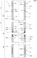
- the 1 shows a schematic longitudinal view of an embodiment of a magnet coil section 1 according to the invention.
- the magnet coil section 1 has a coil carrier 2, which is essentially constructed in the shape of a cylinder jacket overall, cf. the axis (cylinder axis) A of the coil carrier 2, and is largely formed with a tubular base body 3, here made of steel.
- the coil carrier 2 has an insulating body 4, a set 5 of carrier shells 5a, 5b, a set 6 of flange elements 6a, 6b and a set 7 of separating shells 7a, 7b, which sit on the base body 3.
- the magnetic coil arrangement 1 has an HTS strip conductor 10, which is formed here in two parts with a first HTS sub-strip 10a and a second HTS sub-strip 10b.
- the HTS ribbon conductor 10 is here formed with a YBCO layer on a flexible metal substrate, here made of steel.
- the magnetic coil section 1 has two SL subsequent conductors 31, 32.
- the two SL subsequent conductors 31, 32 are designed here as NbTi wires.
- the HTS ribbon conductor 10 has a first end area 11 which is connected to an end area 31a of the first SL subsequent conductor 31 in the area of a first joint 21 . Furthermore, the HTS ribbon conductor 10 has a second end region 12 which is connected to an end region 32a of the second SL follower conductor 32 in the region of a second joint 22 .
- the magnetic coil section 1 is shown partially interrupted in the schematic representation (cf. wave-like impacts) in order to be able to better illustrate the essential aspects of the invention.
- the largest part of the HTS ribbon conductor 10 is in an axially central main area HB of the coil body 2 in a main winding chamber 8 to form a main winding package 9 in a plurality of solenoid configurations Layers, eight layers here, wound up. Note that the axial length of the main winding chamber is 9 in 1 is presented in a greatly abbreviated form. If electric current flows through the HTS strip conductor 10, a magnetic field is generated (typically supplemented by the effect of other magnet coil sections) in a sample volume PV inside the magnet coil section 1, which can be used for NMR measurements, for example.
- a first side area SB1 in which the two joints 21, 22 are also formed, adjoins the main area HB axially at the top.
- the end sections 11, 12 of the HTS strip conductor 10 are transferred from the joints 21, 22 to the main area HB in groove-like depressions 15a, 15b which run in a helical manner.
- the joints 21 , 22 are formed in an axially outer section 14 .
- the end sections 11, 12 of the HTS ribbon conductor 10 and end sections 31a, 32a of the SL sequential conductors 31, 32 are wound one on top of the other on the coil carrier 2 in joint winding chambers 23a, 23b.
- the main area HB is adjoined axially below by a second side area SB2, in which an intermediate joint 16 is formed. Due to its bottom position in the embodiment shown, the intermediate joint 16 is also referred to as a bottom joint.
- feed grooves 17a, 17b for the HTS sub-strips 10a, 10b in the bobbin 2 lead from the main winding chamber 8 to the intermediate joint 16, where the HTS sub-strips 10a, 10b are wound onto the spool carrier 2, lying one on top of the other in an intermediate joint groove 18 and being electrically connected.
- the magnetic coil section 1 uses space in the radial direction for the coil carrier 2, the HTS strip conductor 10 and the SL subsequent conductors 31, 32, at least in the area of the joints 21, 22 (i.e. possibly without extending connection areas of the SL subsequent conductors 31, 32).
- a radial area RBS which here extends from the smallest inner radius RiH of the coil support 2 in the main area HB (wherein in the embodiment the inner radius of the coil carrier 2 is the same everywhere) up to the outer radius RT of the carrier shells 5a, 5b;
- These carrier shells 5a, 5b are here the parts of the coil carrier 2 that extend furthest radially.
- the Figures 2a and 2b illustrate the joints 21, 22 in more detail.
- the end section 31a of the first SL sequence conductor 31 is wound radially on the inside on the insulating body 4 (which is essentially designed as a plastic tube).
- a connection section 31b of the first SL follower conductor 31 leads away in the axial direction, for which purpose a lead-out groove 19a is formed in the bobbin 2.
- a part of the first end section 11 of the HTS strip conductor 10 is wound up radially on the outside of the first SL subsequent conductor 31 and is electrically conductive (preferably superconductive) and connected to one another over a large area.
- the overlap length, based on the HTS strip conductor corresponds to approx. 3-4 turns.
- a peripheral recess is formed as a joint winding chamber 23a (in 1 better to see) in which the wound first end section 11 of the HTS ribbon conductor 10 and the wound end section 31a of the first SL follower 31 are accommodated. Since the insulating body 4 is made of electrically insulating material, such as plastic, the walls of the joint winding chamber 23a are electrically insulating.
- a connecting section 32b of the second SL sequence conductor 32 leads through in a lead-out groove 19b under the first joint 21 or under the joint winding chamber 23a.
- the second SL sequence conductor 32 is also wound onto the insulating body 4 with its end section 32a.
- the connecting portion 32b of the second SL follower conductor 32 extends axially upward.
- a part of the second end section 12 of the HTS strip conductor 10 is wound up radially on the outside of the second SL subsequent conductor 32 and is electrically conductive (preferably superconductive) and connected to one another over a large area.
- the length of the overlap, based on the HTS strip conductor 10, corresponds here to approximately 3-4 turns.
- a peripheral recess is formed as a joint winding chamber 23b (in 1 better to see), in which the wound second end section 12 of the HTS strip conductor 10 and the wound end section 32a of the second SL sequence conductor 32 are accommodated. Due to its formation in the insulating body 4, the joint winding chamber 23b in turn forms electrically insulating walls.
- the first end section 11 of the HTS strip conductor 10 passes under the second joint 22 or under the joint winding chamber 23b in a groove-like depression 24 (cf. also 1 For this).
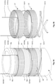
- the Figures 3a to 3d Illustrate the entry and exit of the end sections 11, 12 of the HTS strip conductor 10 in the main winding package 9 in the main winding chamber 8 in more detail.
- the first end section 11 is introduced into the radially innermost ("lowermost") layer 26 and the second end section 12 is led out of the radially outermost (“uppermost”) layer 27 (note that only a few turns of the innermost layer 26 and the outermost layer 27 are shown).
- the two end sections 11, 12 are guided in the coil carrier 2 in the groove-like depressions 15a, 15b.
- the radially outer end section (here the second end section 12 in the groove-like depression 15b) can simply be pushed over the underlying groove-like depression 15a for the radially inner end section (here the first end section 11) in the base body 3 of the Coil carrier 2 are performed.
- the groove depths of the two groove-like depressions 15a, 15b are simply chosen to be different.
- the end sections 11, 12 preferably rest on one another in the crossing area 25; but even if not, the small area of the crossing area 25 for the mechanical support of the end sections 11, 12 is unproblematic.
- a set 5 of carrier shells 5a, 5b is arranged on the base body 3, which provides a support for the radially outer end section 12 of the HTS ribbon conductor 10; the set 5 is placed on the base body 3 of the bobbin 2, and typically screwed.
- the groove-like depression 15b for the radially outer end section 12 runs further, starting from the base body 3 in the set 5 of carrier shells 5a, 5b, to the radially outer layer 27 of the main winding package 8.
- the groove-like depression 15a for the radially inner end section 11 runs from the base body 3 under the set 5 of carrier shells 5a, 5b (see also 1 For this).
- the set 5 of carrier shells 5a, 5b consists of two carrier shells 5a, 5b ("half-shells"), each of which is approximately 180° of the circumference cover.
- the carrier shells 5a, 5b are made of electrically insulating plastic.
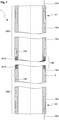
- FIG. 4a to 4d 12 illustrate the formation of the intermediate joint 16 of the magnet coil section of FIG 1 closer.
- HTS strip conductor 10 If a length of HTS strip conductor 10 is to be installed in the magnet coil section that is greater than defect-free HTS strip conductor pieces can be produced (e.g. to generate particularly strong magnetic fields), two HTS sections 10a, 10b can be connected to one another, which together form the HTS strip conductor 10 of the magnet coil section.
- the HTS sections 10a, 10b are derived from two middle layers of the main winding package 8. To avoid complex crossings, only one intermediate joint 16 is typically set (as shown here); however, it is basically also possible to set several intermediate joints.
- a feed groove 17b for the radially lower-lying HTS sub-strip 10a and a feed groove 17a for the radially higher-lying HTS sub-strip 10b lead from the main winding chamber 8 in the second side region SB2 to the intermediate joint 16.
- the Feed grooves 17a, 17b multiple times.
- the feed grooves 17a, 17b run in a helical shape, with the pitch initially increasing axially outwards (here downwards) and then decreasing again near the intermediate joint 16.
- the intermediate joint 16 is set up here by a direct surface connection of the overlapping HTS sub-bands 10a, 10b; the HTS ribbon conductor 10 runs in this area as a "double ribbon" 28 (alternatively, an SL bridge ribbon could also be provided, which overlaps with the HTS sub-ribbons 10a, 10b, not shown).
- the double tape 28 is wound onto the coil carrier 2 in two layers.
- a radially inner layer of the double band 28 is wound directly onto the base body 3;
- the base body 3 forms an intermediate joint groove 18 with a radially inner part 18a, in which the double band 28 is guided.
- a radially outer layer of the double band 28 is formed on a set 7 of separating shells 7a, 7b, which is placed on the base body 3.
- the set 7 of separating shells 7a, 7b forms the intermediate joint groove 18 with a radially outer part 18b.
- the set 7 of separating shells 7a, 7b consists of two separating shells 7a, 7b ("half shells"), each of which covers approximately 180° of the circumference.
- the separating shells 7a, 7b are made of electrically insulating plastic.
- the figure 5 illustrates the course of an end section (shown here using the example of the second end section 12) of the HTS strip conductor 10 from the main winding package 9 to the joint (here the second joint 22).
- the end section 12 is wound with its part belonging to the second joint 22 with immediately axially adjacent turns wound flat on the coil carrier (not shown) in a helical manner; the pitch there is minimal and essentially predetermined by the width of the HTS strip conductor 10 and the winding radius. The pitch then initially increases axially inwards (below) towards the main winding package 9 in order to make do with as little strip length as possible in this transition. It should be noted that HTS ribbon conductors 10 outside of the main winding package 9 can impair the homogeneity of the magnetic field generated in the sample volume.
- the pitch of the helical winding decreases again until it is finally again minimal in the area of the main winding package, essentially determined by the conductor width and the winding radius, since the turns in the main winding package 9 are flat and axially directly adjacent to one another.
- the course of an HTS ribbon conductor 10 (such as its end section 11, 12) is determined by an associated guide in the coil carrier 2 (such as by a groove-like depression 15a, 15b).
- an associated guide in the coil carrier 2 such as by a groove-like depression 15a, 15b.
- a suitable course of the guide, and in particular suitable orientation of a groove base 33 (not shown in figure 5 , see but 1 ) on the one hand the mechanical stress, in particular bending over the short side of the HTS strip conductor 10, can be minimized, and on the other hand the orientation of the HTS strip conductor 10 can be optimized with regard to the local magnetic field.
- the local surface normal FN of the slot base 33 can be aligned at an angle ⁇ to the axis A of the coil carrier 2, which deviates from 90°.
- the local groove base 33 should therefore be aligned in such a way that the local normal component of the magnetic field is nowhere greater in terms of magnitude than a reference normal component, which is already reached as the maximum value of a local normal component at the axial edge of the main winding package 9 in the HTS strip conductor 10.
- the 6 shows an embodiment of a magnet arrangement 40 according to the invention.
- This comprises three nested magnet coil sections 1a, 1b, 1c according to the invention with HTS strip conductors and integrated joints 21, 22 (as, for example, in FIGS Figures 1-5 shown) and here two further nested magnetic coil sections 61, 62, each containing a solenoid-shaped wound LTS wire.
- the magnet coil sections 1a-1c are arranged inside the other magnet coil sections 61, 62.
- the magnetic coil sections 1a-1c are of the same length in the axial direction (cf. axis A) and are aligned.
- the magnetic coil sections 1a-1c and the further magnetic coil sections 61, 62 are electrically connected to one another in series here via the connecting sections 31a, 32a of the SL sequence conductors and further connecting sections 63, 64, with outer joints 41 being used.
- the magnet arrangement 40 can be superconductingly short-circuited via the superconducting switch 42, and thus switched to a continuous current mode ("persistent mode"), in which no external power supply is necessary and the magnetic field in the sample volume PV is kept permanently and practically without drift can be.
- An electrical power source 43 is arranged here in parallel with the switch 42, via which the magnet arrangement 40 can be charged and discharged.
- the gap 45 remaining between adjacent magnet coil sections 1a, 1b or 1b, 1c has here been filled with an electrically insulating filling material 44, here cast material in the hot state, with the cast material hardening in the cold state and mechanically stabilizing the magnet coil sections 1a-1c in relation to one another during operation .
- the radial gap width SB between adjacent magnet coil sections 1a, 1b or 1b, 1c is typically a maximum of 0.6 mm over the entire circumference and the entire axial length (i.e. GSP ⁇ 0.60 mm), and on average is typically a maximum of 0.5 mm (i.e MS ⁇ 0.50mm).
- the magnetic coil sections 1a-1c, the further magnetic coil sections 61, 62, the connecting sections 31b, 32b, the further connecting sections 63, 64, the external joints 41 and the superconducting switch 42 are typically arranged within a cryostat, within which a cryogenic Temperature can be set up (not shown).
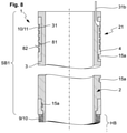
- the 7 shows a further embodiment of a magnet coil section 1 according to the invention, similar to that in FIGS Figures 1 to 5 presented magnet coil section. Only the essential differences are explained.
- the first joint 21 is arranged in the first side area SB1
- the second joint 22 is arranged oppositely in the second side area SB2.
- the two groove-like indentations 15a, 15b which lead the HTS strip conductor 10 from the main winding package 9 to the joints 21, 22, do not require any crossings in this case.
- the connecting sections 31b, 32b of the SL sequence conductors are here led out axially from the coil carrier 2 on opposite sides.
- the 8 shows a further embodiment of a magnet coil section 1 according to the invention, similar to the magnet coil section of FIG 7 , where the section of 7 is limited to the first side area SB1 for the sake of simplicity. Only the main differences are mentioned 7 explained.
- the first joint 21 is formed in the first side area 1 (the second joint is formed here in the second side area, not shown; however, it should be noted that the structure of the first joint 21 shown can also be used analogously if the second joint is also in the first side area is trained).
- the first joint 21 has in the coil carrier 2, here in an insulating body 4 made of electrically insulating material (e.g.
- a helically circumferential joint groove 81 which here has a total of five turns.
- a web 82 of the coil carrier 2 separating the turns remains in each case between the turns. Due to the insulating material of the insulating body 4, the walls of the joint groove 81 are electrically insulating.
- the first SL subsequent conductor 31 is wound up radially on the inside in the joint groove 81 , but this is rolled wide to the width of the HTS strip conductor 10 .
- the first end section 11 of the HTS strip conductor 10 is wound up radially on the outside in the joint groove 81 .
- the rolled SL follower wire 31 and the HTS strip conductor 10 thus rest on one another in the joint groove 81 with one turn each and are electrically (preferably superconductively) connected over their area.
- the joint groove 81 can guide and mechanically stabilize the HTS ribbon conductor 10 and the rolled SL subsequent conductor 31 individually in each turn.
- the first joint 21 here has five circuits of HTS ribbon conductor 10 and SL subsequent conductor 31 around coil carrier 2 .
- the SL subsequent conductor 31 is not rolled wide here, but rather has a rectangular cross section.
- the groove-like recess 15a guides the HTS strip conductor 10 from the first joint 21 to the main winding package 9.
Description
Die Erfindung betrifft eine Magnetspulensektion, umfassend einen im Wesentlichen zylindermantelförmigen Spulenträger, einen Hochtemperatursupraleiter(=HTS)-Bandleiter und einen ersten Supraleiter(=SL)-Folgeleiter mit einem ersten Joint zwischen dem HTS-Bandleiter und dem ersten SL-Folgeleiter,
- wobei der Spulenträger einen Hauptbereich aufweist, in welchem ein Hauptwickelpaket des HTS-Bandleiters solenoidförmig auf den Spulenträger aufgewickelt ist,
- wobei der Spulenträger weiterhin einen ersten Seitenbereich aufweist, der sich axial an einer ersten Seite an den Hauptbereich anschließt, und in welchem ein erster Endabschnitt des HTS-Bandleiters auf den Spulenträger aufgewickelt ist, wobei zumindest in einem axial inneren Abschnitt des ersten Seitenbereichs der erste Endabschnitt des HTS-Bandleiters in einer nutenartigen Vertiefung des Spulenträgers geführt ist,
- und wobei das Hauptwickelpaket des HTS-Bandleiters einen größten Außenradius RaH aufweist und der Spulenträger im Hauptbereich einen kleinsten Innenradius RiH aufweist.
- wherein the coil carrier has a main area in which a main winding package of the HTS strip conductor is wound onto the coil carrier in a solenoid shape,
- wherein the bobbin also has a first side area, which adjoins the main area axially on a first side, and in which a first end section of the HTS tape conductor is wound onto the bobbin carrier, wherein at least in an axially inner section of the first side area, the first end section of the HTS strip conductor is guided in a groove-like depression in the coil carrier,
- and wherein the main winding package of the HTS strip conductor has a largest outer radius RaH and the coil carrier has a smallest inner radius RiH in the main area.
Eine solche Magnetspulensektion ist bekannt geworden aus der
Supraleiter können unterhalb ihrer Sprungtemperatur elektrischen Strom praktisch ohne ohmsche Verluste tragen. Supraleiter werden insbesondere in Magnetspulen zur Erzeugung hoher Magnetfeldstärken eingesetzt, wie sie beispielsweise in der NMR-Spektroskopie benötigt werden.Below their transition temperature, superconductors can carry electric current with practically no ohmic losses. Superconductors are used in particular in magnetic coils to generate high magnetic field strengths, such as are required in NMR spectroscopy, for example.
Mit so genanntem Hochtemperatursupraleiter(=HTS)-Material, beispielsweise auf Basis von YBCO, können besonders hohe supraleitende Stromtragfähigkeiten genutzt werden. Allerdings sind HTS-Materialien in der Regel spröde, so dass diese im Magnetbau meist als Beschichtung auf einem flexiblen Substrat ("Bandleiter") eingesetzt werden. Die HTS-Beschichtung ist sehr empfindlich, so dass der Bandleiter möglichst nicht über seine kurze Seite gebogen werden sollte.Particularly high superconducting current-carrying capacities can be used with so-called high-temperature superconductor (=HTS) material, for example based on YBCO. However, HTS materials are usually brittle, so they are usually used in magnet construction as a coating on a flexible substrate ("tape conductor"). The HTS coating is very sensitive, so the strip conductor should not be bent over its short side if possible.
Tieftemperatursupraleiter(=LTS)-Materialien sind in der Regel metallische Materialien und können in einer Vielzahl von Geometrien eingesetzt werden. Mit NbTi steht dabei auch ein gut duktiles LTS-Material zur Verfügung.Low-temperature superconductor (=LTS) materials are usually metallic materials and can be used in a variety of geometries. With NbTi, a good ductile LTS material is also available.
In einem wichtigen Anwendungsfall zur Erzeugung hoher Magnetfeldstärken wird zur Herstellung einer Magnetspulensektion HTS-Bandleiter auf einen im Wesentlichen zylindermantelförmigen Spulenträger aufgewickelt. Eine Schwierigkeit ist dabei die Gestaltung von Eingängen und Ausgängen des HTS-Bandleiters bzw. die Einrichtung von elektrischen Verbindungen ("Joints") zu Supraleiter(=SL)-Folgeleitern, etwa zu einem leichter zu handhabenden NbTi-Draht.In an important application for generating high magnetic field strengths, HTS strip conductors are wound onto a coil carrier that is essentially in the form of a cylinder jacket to produce a magnet coil section. One difficulty is the design of the inputs and outputs of the HTS strip conductor and the establishment of electrical connections ("joints") to superconductor (=SL) follower conductors, for example to an easier-to-handle NbTi wire.
Die
Die
Die
Die
Die eingangs erwähnte
Aus Manfredo P. do Carmo, Differentialgeometrie von Kurven und Flächen, Vieweg Verlag, Braunschweig 1983, S. 240, wird das Konzept einer Einhüllenden der rektifizierenden Ebenen zu einer parametrisierten Kurve erläutert.From Manfredo P. do Carmo, Differential geometry of curves and surfaces, Vieweg Verlag, Braunschweig 1983, p. 240, the concept of an envelope of the rectifying planes to form a parameterized curve is explained.
Es ist Aufgabe der Erfindung, eine Magnetspulensektion mit hoher Stromtragfähigkeit zur Verfügung zu stellen, die auf kompaktem Raum elektrische Verbindungen zum HTS-Bandleiter zur Verfügung stellen kann.The object of the invention is to provide a magnet coil section with a high current-carrying capacity that can provide electrical connections to the HTS strip conductor in a compact space.
Diese Aufgabe wird erfindungsgemäß gelöst durch eine Magnetspulensektion der eingangs genannten Art, die dadurch gekennzeichnet ist,
- dass die Magnetspulensektion weiterhin einen zweiten SL-Folgeleiter mit einem zweiten Joint zum HTS-Bandleiter umfasst,
- dass in dem ersten Seitenbereich oder in einem zweiten Seitenbereich, der sich axial an einer zweiten Seite an den Hauptbereich anschließt und der ersten Seite gegenüber liegt, ein zweiter Endabschnitt des HTS-Bandleiters auf den Spulenträger aufgewickelt ist,
- dass zumindest in einem axial inneren Abschnitt des ersten oder zweiten Seitenbereichs der zweite Endabschnitt des HTS-Bandleiters in einer nutenartigen Vertiefung des Spulenträgers geführt ist,
- dass in einem axial äußeren Abschnitt des ersten Seitenbereichs zumindest ein Teil des auf dem Spulenträger aufgewickelten ersten Endabschnitts des HTS-Bandleiters mit einem Endabschnitt des ersten SL-Folgeleiters flächig zur Ausbildung des ersten Joints verbunden ist, und zumindest ein Teil des auf dem Spulenträger aufgewickelten zweiten Endabschnitts des HTS-Bandleiters mit einem Endabschnitt des zweiten SL-Folgeleiters zur Ausbildung des zweiten Joints flächig verbunden ist,
- dass der Spulenträger insgesamt, der HTS-Bandleiter insgesamt sowie der erste SL-Folgeleiter zumindest im Bereich des ersten Joints und der zweite SL-Folgeleiter zumindest im Bereich des zweiten Joints innerhalb eines Radialbereichs RBS der Magnetspulensektion verlaufen, mit
- 0,80∗RiH ≤ RBS ≤ 1,2∗RaH, bevorzugt 0,9∗RiH ≤ RBS ≤ 1,1∗RaH, besonders bevorzugt RiH ≤ RBS ≤ RaH,
- und dass weiterhin
- der erste Joint und der zweite Joint jeweils über den gesamten Umfang des Spulenträgers reichen, und/oder
- der erste Joint und der zweite Joint sich jeweils über eine Überlappungslänge, bezogen auf den HTS-Bandleiter, von wenigstens 0,1 m, bevorzugt wenigstens 0,5 m, erstrecken.
- that the magnetic coil section further comprises a second SL follower conductor with a second joint to the HTS strip conductor,
- that in the first side area or in a second side area, which adjoins the main area axially on a second side and is opposite the first side, a second end section of the HTS strip conductor is wound onto the coil carrier,
- that at least in an axially inner section of the first or second side area, the second end section of the HTS strip conductor is guided in a groove-like depression in the coil carrier,
- that in an axially outer section of the first side region at least a part of the first end section of the HTS strip conductor wound on the coil carrier is flat with an end section of the first SL subsequent conductor of the first joint is connected, and at least a part of the second end section of the HTS strip conductor wound on the coil carrier is connected over an area to an end section of the second SL sequence conductor to form the second joint,
- that the coil carrier as a whole, the HTS strip conductor as a whole and the first SL subsequent conductor run at least in the area of the first joint and the second SL subsequent conductor at least in the area of the second joint within a radial area RBS of the magnet coil section
- 0.80 * RiH ≤ RBS ≤ 1.2 * RaH, preferably 0.9 * RiH ≤ RBS ≤ 1.1 * RaH, particularly preferably RiH ≤ RBS ≤ RaH,
- and that continues
- the first joint and the second joint each extend over the entire circumference of the bobbin, and/or
- the first joint and the second joint each extend over an overlap length of at least 0.1 m, preferably at least 0.5 m, based on the HTS ribbon conductor.
Die Erfindung sieht vor, den ersten Joint und den zweiten Joint, mit denen der HTS-Bandleiter elektrisch mit einem ersten SL-Folgeleiter und einem zweiten SL-Folgeleiter verbunden wird, insbesondere supraleitend verbunden wird, jeweils in einem axial äußeren Abschnitt eines Seitenbereichs des Spulenträgers auszubilden, indem der erste und zweite Endabschnitt des HTS-Bandleiters mit Endabschnitten des ersten und zweiten SL-Folgeleiters überlappend flächig miteinander verbunden werden, wobei im Bereich des ersten und zweiten Joints der HTS-Bandleiter und der erste und zweite Folgeleiter auf dem Spulenträger aufgewickelt sind.The invention provides for the first joint and the second joint, with which the HTS strip conductor is electrically connected to a first SL subsequent conductor and a second SL subsequent conductor, in particular is superconductively connected, each in an axially outer section of a side region of the coil former be formed by the first and second end section of the HTS strip conductor being connected to one another in an overlapping manner with end sections of the first and second SL sequence conductor, with the HTS strip conductor and the first and second sequence conductor being wound up on the coil carrier in the region of the first and second joint .
Der HTS-Bandleiter wird vom Hauptbereich, in welchem das Hauptwickelpaket die größte Magnetfeldstärke erzeugt, zunächst über einen axial inneren Abschnitt des Seitenbereichs nach axial weiter außen geführt, wobei eine nutenartige Vertiefung den HTS-Bandleiter führt und mechanisch stabilisiert. Im axial äußeren Abschnitt des Seitenbereichs herrscht eine deutlich niedrigere Magnetfeldstärke und entsprechend auch eine niedrigere mechanisch Krafteinwirkung durch Lorenzkräfte, so dass hier der erste und zweite Joint ausgebildet werden können, ohne die Stromtragfähigkeit oder Stabilität negativ zu beeinflussen. Der erste und zweite Joint sind typischerweise jeweils mindestens um das 1,5-fache des maximalen Außenradius RaH des Hauptwickelpakets vom Hauptwickelpaket axial beabstandet (gemessen Rand zu Rand).The HTS strip conductor is guided from the main area, in which the main winding package generates the greatest magnetic field strength, first over an axially inner section of the side region to the outside, with a groove-like depression guiding the HTS strip conductor and mechanically stabilizing it. A significantly lower magnetic field strength prevails in the axially outer section of the side area and accordingly also a lower mechanical force effect due to Lorenz forces, so that the first and second joint can be formed here without negatively influencing the current carrying capacity or stability. The first and second joints are typically each spaced axially from the main winding pack (measured edge to edge) by at least 1.5 times the maximum outer radius RaH of the main winding pack.
Da die Wicklung des HTS-Bandleiters vom Hauptbereich über den axial inneren Abschnitt bis in den axial äußeren Abschnitt mit dem Joint im Wesentlichen auf dem Spulenträger einfach weitergewickelt wird (wenn auch zumindest überwiegend mit größerer Ganghöhe als im Hauptwickelpaket, um Inhomogenitäten des Magnetfelds zu minimieren), und insbesondere keine Verdrehung (Verdrillung, Twist) des HTS-Bandleiters nötig ist, ist der erfindungsgemäße Aufbau mechanisch robust und der HTS-Bandleiter im Allgemeinen auch für die Stromtragfähigkeit günstig zum erzeugten Magnetfeld orientiert. Auch dies trägt zu einer hohen Stromtragfähigkeit bei.Since the winding of the HTS strip conductor is simply wound further from the main area via the axially inner section to the axially outer section with the joint, essentially on the coil carrier (albeit at least predominantly with a greater pitch than in the main winding package, in order to minimize inhomogeneities in the magnetic field) , and in particular no twisting (twisting, twist) of the HTS strip conductor is necessary, the structure according to the invention is mechanically robust and the HTS strip conductor is generally also oriented favorably to the generated magnetic field for the current-carrying capacity. This also contributes to a high current-carrying capacity.
Durch Aufwickeln des ersten und zweiten Joints auf den Spulenträger können auf kompaktem Raum vergleichsweise große Überlappungsflächen (oder Überlappungslängen) eingerichtet werden, wodurch die elektrische Verbindung zuverlässig und ohne merklichen ohmschen Widerstand leicht eingerichtet werden kann. Die flächige (elektrisch leitende) Verbindung von HTS-Bandleiter und SL-Folgeleiter kann beispielsweise durch Löten erfolgen; bevorzugt ist die Verbindung supraleitend.By winding the first and second joint onto the coil carrier, comparatively large overlapping areas (or overlapping lengths) can be set up in a compact space, as a result of which the electrical connection can be set up easily and reliably without noticeable ohmic resistance. The planar (electrically conductive) connection of HTS ribbon conductor and SL subsequent conductor can be done, for example, by soldering; preferably the compound is superconducting.
Dadurch, dass der wesentliche Aufbau der Magnetspulensektion auf den Radialbereich RBS beschränkt ist, also bis auf eine Abweichung von maximal 20% (bevorzugt maximal 10%, besonders bevorzugt vollständig) innerhalb des durch den kleinsten Innenradius RiH des Spulenträgers im Hauptbereich und den größten Außenradius RaH des Hauptwickelpakets vorgegebenen Radiusintervalls liegt, kann eine hohe effektive supraleitende Stromdichte erreicht werden. Zudem sind dann erfindungsgemäße Magnetspulensektionen gut ineinander schachtelbar, um in Summe hohe Magnetfeldstärken zu erzeugen. Auch begrenzt verfügbare HTS-Bandleiter-Längen (z.B. von derzeit ca. 300 m) können in einer erfindungsgemäßen Magnetspulensektion effizient verbaut werden, wofür nur vergleichsweise geringe radiale Gesamtwandstärken der Magnetspulensektion benötigt werden. Dann können auf geringem Raum besonders viele Magnetspulensektionen geschachtelt werden.Due to the fact that the main structure of the magnet coil section is limited to the radial area RBS, i.e. up to a maximum deviation of 20% (preferably maximum 10%, particularly preferably completely) within the smallest inner radius RiH of the coil carrier in the main area and the largest outer radius RaH of the main winding pack lies within the predetermined radius interval, a high effective superconducting current density can be achieved. In addition, magnet coil sections according to the invention can then be easily nested in one another in order to generate high magnetic field strengths overall. Also limited available HTS ribbon cable lengths (eg currently approx. 300 m) can be installed efficiently in a magnet coil section according to the invention, for which only comparatively small overall radial wall thicknesses of the magnet coil section are required. A particularly large number of magnet coil sections can then be nested in a small space.
Die zumindest im axial inneren Abschnitt des ersten und/oder zweiten Seitenbereichs verlaufenden nutenartigen Vertiefungen verlaufen typischerweise helixartig, mit variabler Steigung und (geringfügig) variablem Radius. Die nutenartigen Vertiefungen (und ggf. Jointnuten, Zuführungsnuten und Zwischenjointnuten, siehe unten) führen den HTS-Bandleiter mit sehr geringem Spiel (beispielsweise mit einem Spiel in Querrichtung ≤ 1/10 der Leiterbreite); der HTS-Bandleiter wird an jeder Windung einzeln gestützt.The groove-like indentations running at least in the axially inner section of the first and/or second side region typically run helically, with a variable pitch and (slightly) variable radius. The groove-like indentations (and possibly joint grooves, feed grooves and intermediate joint grooves, see below) guide the HTS strip conductor with very little play (for example with a play in the transverse direction ≦1/10 of the conductor width); the HTS strip conductor is individually supported at each turn.
Bevorzugt sind die nutenartigen Vertiefungen (und ggf. Jointnuten, Zuführungsnuten und Zwischenjointnuten, siehe unten) so ausgelegt, dass der HTS-Bandleiter ohne Biegung oder zumindest mit minimierter Biegung über die kurze Seite (also ohne oder mit minimiertem "hard bending") geführt wird. Man beachte, dass es bei gegebenem (dabei aber wählbarem), durch eine Mittellinie der Nut definiertem Nutverlauf genau eine zugeordnete abwickelbare Fläche, die so genannte Einhüllende der rektifizierenden Ebenen (vgl.
Typischerweise weist der erste SL-Folgeleiter eine niedrigere Sprungtemperatur auf als der HTS-Bandleiter, und der zweite SL-Folgeleiter weist eine niedrigere Sprungtemperatur auf als der HTS-Bandleiter. Insbesondere können der erste SL-Folgeleiter und der zweite SL-Folgeleiter von gleichem Typ (insbesondere vom gleichen SL-Material) sein. Die SL-Folgeleiter sind typischerweise metallisch duktil und dadurch leicht handhabbar; typischerweise ist der SL-Folgedraht ein NbTi-Draht. Mit den SL-Folgeleitern kann die weitere (externe) elektrische Anbindung der Magnetspulensektion erfolgen.Typically, the first SL sequence conductor has a lower critical temperature than the HTS ribbon conductor and the second SL sequence conductor has a lower critical temperature than the HTS ribbon conductor. In particular, the first SL subsequent conductor and the second SL subsequent conductor can be of the same type (in particular of the same SL material). The SL subsequent conductors are typically metallically ductile and therefore easy to handle; typically the SL follower wire is an NbTi wire. The further (external) electrical connection of the magnet coil section can be made with the SL subsequent conductors.
Im Rahmen der Erfindung ist es auch möglich, am ersten und/oder zweiten Joint zunächst (jeweils) den HTS-Bandleiter und den SL-Folgeleiter flächig zu verbinden ("Joint"), und sodann den SL-Folgeleiter wiederum mit einem SL-Drittleiter flächig zu verbinden ("Drittleiterjoint"), und dabei den SL-Folgeleiter und den SL-Drittleiter wiederum im Seitenbereich im axial äußeren Abschnitt auf dem Spulenträger aufzuwickeln. Insgesamt kann durch den Joint und den Drittleiterjoint ein so genannter Brückenjoint ("Bridgejoint") angelegt werden, wobei der SL-Folgeleiter als so genanntes Brückenband dient. Der SL-Drittleiter wird dann aus der Magnetspulensektion zur weiteren elektrischen Verbindung herausgeführt; für ihn gilt das ansonsten für den SL-Folgeleiter gesagte entsprechend.Within the scope of the invention, it is also possible to first (respectively) connect the HTS strip conductor and the SL subsequent conductor over a large area (“joint”) on the first and/or second joint, and then the SL subsequent conductor in turn with an SL third conductor to connect over a large area (“third conductor joint”), and thereby to wind up the SL subsequent conductor and the SL third conductor in the side area in the axially outer section on the bobbin. Overall, a so-called bridge joint can be created through the joint and the third conductor joint, with the SL subsequent conductor serving as a so-called bridge band. The SL third conductor is then brought out of the magnetic coil section for further electrical connection; for him, what was otherwise said for the SL follower applies accordingly.
Die Erfindung sieht vor, dass der erste Joint und der zweite Joint jeweils über den gesamten Umfang des Spulenträgers reichen, und/oder dass der erste Joint und der zweite Joint sich jeweils über eine Überlappungslänge, bezogen auf den HTS-Bandleiter, von wenigstens 0,1 m, bevorzugt wenigstens 0,5 m, erstrecken. Im Rahmen der Erfindung können problemlos große Überlappungsflächen bzw. Überlappungslängen eingerichtet werden. Dadurch können der erste und zweite Joint besonders zuverlässig mit hoher Stromtragfähigkeit und praktisch verschwindendem ohmschen Widerstand ausgebildet werden. Typischerweise reichen der erste und zweite Joint jeweils mit einer Vielzahl von Windungen, beispielsweise wenigstens 3 Windungen oder wenigstens 5 Windungen, um den Spulenträger herum, sowohl bezüglich des HTS-Bandleiters als auch bezüglich des SL-Folgeleiters. Man beachte, dass insbesondere bei Nutzung einer Jointwickelkammer die Zahl der Windungen des HTS-Bandleiters und des SL-Folgeleiters unterschiedlich sein können.The invention provides that the first joint and the second joint each extend over the entire circumference of the coil support, and/or that the first joint and the second joint each have an overlap length, based on the HTS ribbon conductor, of at least 0 1 m, preferably at least 0.5 m. Within the scope of the invention, large overlapping areas or overlapping lengths can be set up without any problems. As a result, the first and second joint can be formed particularly reliably with a high current-carrying capacity and an ohmic resistance that practically disappears. Typically, the first and second joints each extend with a large number of turns, for example at least 3 turns or at least 5 turns, around the coil carrier, both with regard to the HTS ribbon conductor and with regard to the SL follower conductor. It should be noted that the number of turns of the HTS strip conductor and the SL subsequent conductor can be different, particularly when using a joint winding chamber.
Bevorzugt ist eine Ausführungsform, bei der im Hauptbereich der Spulenträger eine umlaufende ringförmige Vertiefung als Hauptwickelkammer aufweist, in der das Hauptwickelpaket des HTS-Bandleiters in mehreren Lagen solenoidförmig aufgewickelt ist. Die Hauptwickelkammer ist leicht einzurichten, und kann die Windungen des HTS-Bandleiters axial umfassen und dadurch mechanisch stabilisieren. Bevorzugt fluchtet der obere (radial äußere) Rand der Vertiefung der Hauptwickelkammer im Spulenträger im Wesentlichen (z. B. mit einer maximalen Abweichung von 10%, bezogen auf RaH) mit der Oberseite (radialen Außenseite) des Hauptwickelpakets, so dass sich eine im Wesentlichen stufenlose Außenseite der Magnetspulensektion ergibt.An embodiment is preferred in which the main area of the coil carrier has a circumferential annular recess as the main winding chamber. in which the main winding package of the HTS strip conductor is wound up in several layers in the form of a solenoid. The main winding chamber is easy to set up and can axially enclose the windings of the HTS strip conductor and thereby stabilize them mechanically. Preferably, the upper (radially outer) edge of the depression of the main winding chamber in the coil carrier is essentially aligned (e.g. with a maximum deviation of 10%, based on RaH) with the upper side (radially outside) of the main winding package, so that an essentially stepless outside of the magnet coil section results.
Eine bevorzugte Ausführungsform sieht vor, dass im axial äußeren Abschnitt des ersten Seitenbereichs der Spulenträger eine umlaufende ringförmige Vertiefung als erste Jointwickelkammer aufweist, in der zumindest der Teil des ersten Endabschnitts des HTS-Bandleiters mit mehreren nebeneinander liegenden Windungen und der Endabschnitt des ersten SL-Folgeleiters mit mehreren nebeneinander liegenden Windungen übereinander liegend aufgewickelt sind,
und/oder dass im axial äußeren Abschnitt des ersten oder zweiten Seitenbereichs der Spulenträger eine umlaufende ringförmige Vertiefung als zweite Jointwickelkammer aufweist, in der zumindest der Teil des zweiten Endabschnitts des HTS-Bandleiters mit mehreren nebeneinander liegenden Windungen und der Endabschnitt des zweiten SL-Folgeleiters mit mehreren nebeneinander liegenden Windungen übereinander liegend aufgewickelt sind. Eine umlaufende Vertiefung als erste oder zweite Jointwickelkammer ist leicht einzurichten, und kann den Joint axial umfassen und dadurch mechanisch stabilisieren. Typischerweise sind der erste und zweite SL-Folgeleiter jeweils radial innen und der HTS-Bandleiter radial außen angeordnet, wobei der HTS-Bandleiter so orientiert ist, das dessen HTS-Schicht nach innen, also zum SL-Folgeleiter hin, zeigt. Typischerweise sind weiterhin die SL-Folgeleiter weniger breit als der HTS-Bandleiter, so dass im Verbindungsbereich (Überlappungsbereich) mehr Windungen des SL-Folgeleiters als Windungen des HTS-Bandleiters vorhanden sind.A preferred embodiment provides that in the axially outer section of the first side area the coil carrier has a circumferential annular depression as the first joint winding chamber, in which at least the part of the first end section of the HTS strip conductor with a plurality of adjacent turns and the end section of the first SL sequence conductor are wound one on top of the other with several adjacent turns,
and/or that in the axially outer section of the first or second side area of the coil carrier has a circumferential annular depression as a second joint winding chamber, in which at least the part of the second end section of the HTS strip conductor with a plurality of adjacent turns and the end section of the second SL sequence conductor with several adjacent turns are wound one on top of the other. A circumferential recess as a first or second joint winding chamber is easy to set up and can axially surround the joint and thereby stabilize it mechanically. Typically, the first and second SL subsequent conductors are each arranged radially on the inside and the HTS strip conductor is arranged radially on the outside, with the HTS strip conductor being oriented in such a way that its HTS layer points inwards, ie towards the SL subsequent conductor. Typically, the SL subsequent conductors are also less wide than the HTS ribbon conductor, so that in the connection area (overlapping region) there are more turns of the SL subsequent conductor than turns of the HTS ribbon conductor.
Bei einer vorteilhaften Weiterentwicklung ist der Spulenträger im Bereich der Wände der ersten Jointwickelkammer und/oder der Wände der zweiten Jointwickelkammer aus einem elektrisch isolierenden Material, insbesondere einem Kunststoff, ausgebildet. Dies kann beispielsweise dadurch eingerichtet werden, dass der Spulenträger im Bereich der Jointwickelkammer mit einem Kunststoffrohr oder Kunststoffschalen gefertigt ist, das oder die bei der Fertigung des Spulenkörpers in den ansonsten metallischen Spulenträger (Grundkörper) integriert wurde(n). Die elektrische Isolation der Wickelkammer verhindert Kurzschlussströme zwischen den Leitern und dem metallischen Spulenträger und Ströme über diesen zwischen den Joints.In an advantageous further development, the coil carrier is made of an electrically insulating material, in particular a plastic, in the area of the walls of the first joint winding chamber and/or the walls of the second joint winding chamber. This can be set up, for example, by the coil carrier being manufactured with a plastic tube or plastic shells in the area of the joint winding chamber, which was/were integrated into the otherwise metallic coil carrier (base body) during manufacture of the coil body. The electrical insulation of the winding chamber prevents short-circuit currents between the conductors and the metallic coil carrier and currents via these between the joints.
Vorteilhaft ist auch eine Ausführungsform, die vorsieht,
- dass im axial äußeren Abschnitt des ersten Seitenbereichs der Spulenträger eine erste Jointnut aufweist, die wenigstens einmal, bevorzugt mehrfach, um den Spulenträger führt, und in der zumindest der Teil des ersten Endabschnitts des HTS-Bandleiters und der Endabschnitt des ersten SL-Folgeleiters übereinander liegend geführt sind,
- und/oder dass im axial äußeren Abschnitt des ersten oder zweiten Seitenbereichs der Spulenträger eine zweite Jointnut aufweist, die wenigstens einmal, bevorzugt mehrfach, um den Spulenträger führt, in der zumindest der Teil des zweiten Endabschnitts des HTS-Bandleiters und der Endabschnitt des zweiten SL-Folgeleiters übereinander liegend geführt sind.
- that in the axially outer section of the first side area of the coil carrier has a first joint groove, which runs around the coil carrier at least once, preferably several times, and in which at least the part of the first end section of the HTS strip conductor and the end section of the first SL follower lie on top of one another are guided
- and/or that in the axially outer section of the first or second side area of the coil carrier has a second joint groove, which runs around the coil carrier at least once, preferably several times, in which at least the part of the second end section of the HTS ribbon conductor and the end section of the second SL -Following ladder are performed one above the other.
Durch die Jointnut kann eine sehr genaue Führung des HTS-Bandleiters und des SL-Folgeleiters erfolgen, etwa um die mechanische Belastung durch Kräfte (insbesondere Lorenzkräfte) zu minimieren und/oder die Ausrichtung in Hinblick auf die Stromtragfähigkeit zu optimieren. In der jeweiligen Jointnut verlaufen "ein" HTS-Bandleiter und "ein" SL-Folgeleiter gemeinsam um den Spulenträger; die Jointnut verläuft typischerweise helixförmig.The joint groove allows the HTS ribbon conductor and the SL secondary conductor to be guided very precisely, for example in order to minimize the mechanical stress caused by forces (in particular Lorenz forces) and/or to optimize the alignment with regard to the current-carrying capacity. In the respective joint groove, "one" HTS tape conductor and "one" SL follower conductor run together around the coil carrier; the joint groove typically runs helically.
Bevorzugt ist eine Weiterbildung dieser Ausführungsform, bei der der Spulenträger im Bereich der Wände der ersten Jointnut und/oder der Wände der zweiten Jointnut aus einem elektrisch isolierenden Material, insbesondere einem Kunststoff, ausgebildet ist. Dadurch können Kurzschlussringe im Bereich des jeweiligen Joints vermieden werden.A further development of this embodiment is preferred, in which the coil carrier is in the region of the walls of the first joint groove and/or the walls of the second Joint groove is formed from an electrically insulating material, in particular a plastic. This means that short-circuit rings can be avoided in the area of the respective joint.
Besonders bevorzugt ist eine Ausführungsform, bei der in dem ersten Seitenbereich auch der zweite Endabschnitt des HTS-Bandleiters auf den Spulenträger aufgewickelt ist,
insbesondere wobei im axial inneren Abschnitt des ersten Seitenbereichs die nutenartigen Vertiefungen des ersten Endabschnitts und des zweiten Endabschnitts sich mehrfach kreuzen.An embodiment is particularly preferred in which the second end section of the HTS strip conductor is also wound onto the coil carrier in the first side region.
In particular, the groove-like depressions of the first end section and of the second end section intersect several times in the axially inner section of the first side region.
Durch Ausbildung des ersten und zweiten Joints im ersten Seitenbereich, also auf derselben (axialen) Seite des Hauptbereichs bzw. der Hauptwickelkammer, kann ein besonders kompakter Aufbau erreicht werden, denn der axial innere Abschnitt des ersten Seitenbereichs kann dann dazu genutzt werden, sowohl den ersten Joint als auch den zweiten Joint vom Hauptbereich entfernt im niedrigen Magnetfeld anzuordnen. Zudem können externe elektrische Verbindungen (mittels der SL-Folgeleiter) auf einer Seite konzentriert werden, wodurch der Zugang in einem Kryostaten von nur einer Seite (etwa von oben) begünstigt ist; ein Zugang von nur einer Seite ist bei einem vertikalen Magentaufbau der Regelfall. Durch das Gestatten von Kreuzungen wird die Führung des HTS-Bandleiters erheblich vereinfacht; insbesondere kann eine zu schnelle Änderung der Steigung der (helixartigen) Wicklungen der HTS-Bandleiter vom Hauptbereich weg vermieden werden und damit die Biegung des HTS-Bandleiters um die kurze Seite minimiert oder ganz eliminiert werden. Alternativ zu dieser Ausführungsform können auch der erste Endabschnitt und der zweite Endabschnitt des HTS-Bandleiters auf unterschiedlichen Seitenbereichen aufgewickelt sein.By forming the first and second joint in the first side area, i.e. on the same (axial) side of the main area or the main winding chamber, a particularly compact structure can be achieved, because the axially inner section of the first side area can then be used for both the first Place both joint and second joint away from the main area in the low magnetic field. In addition, external electrical connections (by means of the SL follower conductors) can be concentrated on one side, which favors access in a cryostat from only one side (e.g. from above); access from only one side is the norm with a vertical magnet structure. Allowing crossings greatly simplifies routing of the HTS ribbon conductor; In particular, an excessively rapid change in the pitch of the (helical) windings of the HTS ribbon conductors away from the main region can be avoided, and the bending of the HTS ribbon conductor around the short side can thus be minimized or completely eliminated. As an alternative to this embodiment, the first end section and the second end section of the HTS strip conductor can also be wound up on different side areas.
Bevorzugt ist eine Weiterbildung dieser Ausführungsform, die vorsieht, dass der Spulenträger in einem axial an die Hauptwickelkammer anschließenden Übergangsbereich des axial inneren Abschnitts des ersten Seitenbereichs mit einem Satz von Trägerschalen ausgebildet ist, die auf dem übrigen Spulenträger aufliegen und zusammen den übrigen Spulenträger ringförmig umgreifen,
und dass im Übergangsbereich eine der nutenartigen Vertiefungen für den ersten Endabschnitt und den zweiten Endabschnitt des HTS-Bandleiters in dem Satz von Trägerschalen ausgebildet ist, und die andere der nutenartigen Vertiefungen für den ersten Endabschnitt und den zweiten Endabschnitt des HTS-Bandleiters radial unter dem Satz von Trägerschalen im übrigen Spulenträger ausgebildet ist, wobei in dem Übergangsbereich der erste und zweite Endabschnitt des HTS-Bandleiters sich wenigstens einmal kreuzen. Meist umfasst das Hauptwickelpaket wenigstens 4 Wickellagen, oft auch wenigstens 10 oder wenigstens 40 Wickellagen, so dass am Eingang und Ausgang des Hauptwickelpakets ein erheblicher Radiusunterschied der Endabschnitte des HTS-Bandleiters vorhanden ist. Der Endabschnitt der HTS-Bandleiters in der radial äußeren nutenartigen Vertiefung kann auf den Trägerschalen mechanisch stabil aufliegen, auch wenn der andere Endabschnitt des HTS-Bandleiters radial deutlich weiter innen im (übrigen) Spulenträger (Grundkörper) verläuft und bei geringer Ganghöhe über einen erheblichen Anteil des Umfangs des Spulenträgers, z.B. wenigstens den halben Umfang, überkreuzt (überlappt) werden muss. Typischerweise steigt der Radius der radial inneren nutenartigen Vertiefung im übrigen Spulenträger im Übergangsbereich nach axial außen hin an, um den zugehörigen Endabschnitt des HTS-Bandleiters zur Außenseite des Spulenträgers zu führen. Typischerweise werden zwei Trägerschalen ("Halbschalen") als Satz eingesetzt.A further development of this embodiment is preferred, which provides that the coil carrier in a transition region of the axially inner section of the first side region, which is axially adjacent to the main winding chamber, is provided with a set of carrier shells is formed, which rest on the rest of the coil carrier and together encompass the rest of the coil carrier in the shape of a ring,
and that in the transition region one of the groove-like depressions for the first end section and the second end section of the HTS ribbon conductor is formed in the set of carrier shells, and the other of the groove-like depressions for the first end section and the second end section of the HTS ribbon conductor is formed radially below the set formed by carrier shells in the rest of the coil carrier, the first and second end sections of the HTS ribbon conductor crossing at least once in the transition area. The main winding package usually includes at least 4 winding layers, often also at least 10 or at least 40 winding layers, so that there is a considerable difference in radius of the end sections of the HTS strip conductor at the entrance and exit of the main winding package. The end section of the HTS ribbon conductor in the radially outer groove-like recess can rest mechanically stable on the carrier shells, even if the other end section of the HTS ribbon conductor runs radially much further inward in the (remaining) coil carrier (base body) and with a low pitch over a significant proportion of the circumference of the bobbin, eg at least half the circumference, must be crossed (overlapped). Typically, the radius of the radially inner groove-like depression in the rest of the coil carrier increases axially outwards in the transition region in order to guide the associated end section of the HTS strip conductor to the outside of the coil carrier. Typically, two carrier shells ("half shells") are used as a set.
Bei einer anderen bevorzugten Weiterbildung sind im axial inneren Abschnitt des ersten Seitenbereichs die nutenartigen Vertiefungen für den ersten Endabschnitt und den zweiten Endabschnitt des HTS-Bandleiters in wenigstens einem Kreuzungsbereich der nutenartigen Vertiefungen mit einer unterschiedlichen Nutentiefe ausgebildet. Durch die Einrichtung der Kreuzungsbereiche kann eine größere Freiheit bei der Führung der beiden Endabschnitte des HTS-Bandleiters erhalten werden, insbesondere um mechanische Belastungen zu minimieren, etwa die Biegung um die kurze Seite. Bevorzugt entspricht der Unterschied in der Nutentiefe mindestens der Höhe des HTS-Bandleiters, so dass die Endabschnitte des HTS-Bandleiters im Kreuzungsbereich stabil aneinander vorbei geführt werden.In another preferred development, the groove-like depressions for the first end section and the second end section of the HTS strip conductor are formed with a different groove depth in at least one crossing area of the groove-like depressions in the axially inner section of the first side region. By setting up the crossing areas, greater freedom can be obtained when guiding the two end sections of the HTS ribbon conductor, in particular in order to minimize mechanical stresses, such as bending around the short side. The difference in the groove depth preferably corresponds to at least the height of the HTS ribbon conductor, so that the end sections of the HTS strip conductor in the crossing area are guided past one another in a stable manner.
Bevorzugt ist eine Weiterbildung, bei der im axial äußeren Abschnitt des ersten Seitenbereichs eine nutenartige Vertiefung für denjenigen Endabschnitt des HTS-Bandleiters, welcher den axial weiter außen liegenden Joint aufweist, radial innerhalb des axial weiter innen liegenden Joints verläuft. Dieser Aufbau ist einfach und nutzt den im Spulenkörper verfügbaren Bauraum in günstiger Weise aus.A further development is preferred in which in the axially outer section of the first side region a groove-like depression for that end section of the HTS strip conductor which has the axially further outside joint runs radially inside the axially further inside joint. This structure is simple and makes good use of the space available in the coil former.
Ebenso bevorzugt ist eine Weiterbildung, bei der im axial äußeren Abschnitt des ersten Seitenbereichs eine Ausleitungsnut für denjenigen SL-Folgeleiter, der Teil des axial weiter innen liegenden Joints ist, radial innerhalb des axial weiter außen liegenden Joints verläuft. Dieser Aufbau ist wiederum einfach und nutzt den im Spulenkörper verfügbaren Bauraum in günstiger Weise aus.Also preferred is a further development in which, in the axially outer section of the first side region, a lead-out groove for the SL subsequent conductor that is part of the joint located further axially to the inside runs radially inside the joint located further axially to the outside. This structure is again simple and uses the space available in the coil body in a favorable manner.
Bevorzugt ist weiterhin eines Ausführungsform einer erfindungsgemäßen Magnetspulensektion, bei der der HTS-Bandleiter wenigstens zwei HTS-Teilbänder aufweist, die seriell über wenigstens einen Zwischenjoint leitend miteinander verbunden sind,
- wobei die HTS-Teilbänder im Bereich des wenigstens einen Zwischenjoints im ersten Seitenbereich oder im zweiten Seitenbereich auf dem Spulenträger aufgewickelt sind,
- insbesondere wobei im Bereich des wenigstens einen Zwischenjoints die HTS-Teilbänder mit einem gemeinsamen Supraleiter(=SL)-Brückenband verbunden sind. Durch die Verwendung der HTS-Teilbänder kann die gesamte nutzbare Länge von HTS-Bandleiter in der Magnetspulensektion gegenüber der verfügbaren (fehlerfrei fertigbaren) Länge von HTS-Bandleiter-Stücken vergrößert werden. Bevorzugt bildet der Zwischenjoint ein HTS-HTS-Joint aus; es ist aber auch möglich, den Zwischenjoint axial vom Hauptwickelpaket ausreichend entfernt anzuordnen, so dass beispielsweise auch ein SL-Brückenband aus LTS-Material genutzt werden kann.
- wherein the HTS sub-strips are wound on the coil carrier in the area of the at least one intermediate joint in the first side area or in the second side area,
- In particular, the HTS sub-bands are connected to a common superconductor (=SL) bridge band in the area of the at least one intermediate joint. By using the HTS sub-strips, the total usable length of HTS strip conductors in the magnet coil section can be increased compared to the available length (which can be produced without errors) of HTS strip conductor pieces. The intermediate joint preferably forms an HTS-HTS joint; It is also It is possible to arrange the intermediate joint at a sufficient distance axially from the main winding package, so that, for example, an SL bridge tape made of LTS material can also be used.
Eine bevorzugte Weiterbildung dieser Ausführungsform sieht vor, dass der Spulenträger im ersten Seitenbereich oder im zweiten Seitenbereich zwei Zuführungsnuten für die HTS-Teilbänder ausbildet, die von der Hauptwickelkammer zum Bereich des wenigstens einen Zwischenjoints führen, und der Spulenträger im Bereich des Zwischenjoints eine Zwischenjointnut für die HTS-Teilbänder ausbildet. In den Zuführungsnuten und der Zwischenjointnut kann der HTS-Bandleiter an jeder einzelnen Windung gestützt und geführt werden, insbesondere in Hinblick auf eine minimierte Biegung über die kurze Seite des HTS-Bandleiters und eine günstige Orientierung zum Magnetfeld.A preferred development of this embodiment provides that the coil carrier forms two feed grooves for the HTS sub-strips in the first side area or in the second side area, which lead from the main winding chamber to the area of the at least one intermediate joint, and the coil carrier in the area of the intermediate joint forms an intermediate joint groove for the HTS sub-bands forms. In the feed grooves and the intermediate joint groove, the HTS ribbon conductor can be supported and guided at each individual turn, in particular with regard to minimized bending over the short side of the HTS ribbon conductor and a favorable orientation to the magnetic field.
Bevorzugt ist dabei vorgesehen, dass der Spulenträger im Bereich des wenigstens einen Zwischenjoints mit einem Satz von Trennschalen ausgebildet ist, die auf dem übrigen Spulenträger aufliegen und zusammen den übrigen Spulenträger ringförmig umgreifen,
und dass ein radial äußerer Teil der Zwischenjointnut in dem Satz von Trennschalen ausgebildet ist, und ein radial innerer Teil der Zwischenjointnut radial unter dem Satz von Trennschalen im übrigen Spulenträgerausgebildet ist, insbesondere wobei der Satz von Trennschalen einen Bereich für den Radiuswechsel des Zwischenjoints aufweist. Mittels der Trennschalen ist es möglich, die Zwischenjointnut mit zwei übereinander liegenden Lagen auszubilden, so dass der Zwischenjoint in axialer Richtung hin- und zurückführend über denselben axialen Bereich gewickelt werden kann. Typischerweise werden zwei Trennschalen ("Halbschalen)" als Satz eingesetzt. Der Bereich für den Radiuswechsel kann insbesondere einen Durchführungsschlitz in dem Satz von Trennschalen aufweisen.It is preferably provided that the coil carrier is designed with a set of separating shells in the area of the at least one intermediate joint, which rest on the rest of the coil carrier and together encompass the rest of the coil carrier in a ring shape,
and that a radially outer part of the intermediate joint groove is formed in the set of separator shells and a radially inner part of the intermediate joint groove is formed radially below the set of separator shells in the rest of the bobbin, in particular wherein the set of separator shells has an area for the radius change of the intermediate joint. By means of the separating shells, it is possible to form the intermediate joint groove with two layers lying one on top of the other, so that the intermediate joint can be wound back and forth in the axial direction over the same axial area. Typically, two separating shells ("half shells)" are used as a set. In particular, the area for changing the radius can have a feed-through slot in the set of separating shells.
Bei einer anderen Weiterbildung ist vorgesehen, dass in dem ersten Seitenbereich auch der zweite Endabschnitt des HTS-Bandleiters auf den Spulenträger aufgewickelt ist, und die HTS-Teilbänder im Bereich des wenigstens einen Zwischenjoints im zweiten Seitenbereich auf dem Spulenträger aufgewickelt sind, insbesondere wobei der Spulenträger mit seiner Zylinderachse vertikal sowie dem zweiten Seitenbereich unten und dem ersten Seitenbereich oben ausgerichtet ist. Diese Bauform vereinfacht die Führung des HTS-Bandleiters. Zudem ist der Aufbau sehr kompakt.In another development, it is provided that the second end section of the HTS strip conductor is also placed on the coil carrier in the first side area is wound up, and the HTS sub-strips are wound up on the coil carrier in the region of the at least one intermediate joint in the second side region, in particular with the coil carrier being aligned with its cylinder axis vertical and the second side region at the bottom and the first side region at the top. This design simplifies the routing of the HTS strip conductor. In addition, the structure is very compact.
Bei einer vorteilhaften Ausführungsform ist vorgesehen, dass
- die nutenartigen Vertiefungen, in denen der HTS-Bandleiter zumindest im axial innen liegenden Abschnitt des ersten und/oder zweiten Seitenbereichs geführt sind,
- und gegebenenfalls Jointnuten, in denen die ersten und/oder zweiten Endabschnitte des HTS-Bandleiters im axial äußeren Abschnitt des ersten und/oder zweiten Seitenbereichs geführt sind,
- und gegebenenfalls Zuführungsnuten und Zwischenjointnuten für mit einem Zwischenjoint verbundene HTS-Teilbänder des HTS-Bandleiters,
- the groove-like depressions in which the HTS strip conductor is guided at least in the axially inner section of the first and/or second side area,
- and optionally joint grooves in which the first and/or second end sections of the HTS strip conductor are guided in the axially outer section of the first and/or second side area,
- and, if necessary, feed grooves and intermediate joint grooves for HTS sub-strips of the HTS strip conductor connected to an intermediate joint,
Weiterhin bevorzugt ist eine Ausführungsform, die vorsieht,
- dass der erste SL-Folgeleiter und/oder der zweite SL-Folgeleiter ein Tieftemperatursupraleiter(=LTS)-Material, insbesondere NbTi, enthalten,
- und/oder dass der erste SL-Folgeleiter und/oder der zweite SL-Folgeleiter MgB2 enthalten,
- und/oder dass der HTS-Bandleiter ReBCO, insbesondere YBCO, oder Bi2223 enthält.
- that the first SL subsequent conductor and/or the second SL subsequent conductor contain a low-temperature superconductor (=LTS) material, in particular NbTi,
- and/or that the first SL subsequent conductor and/or the second SL subsequent conductor contain MgB 2 ,
- and/or that the HTS strip conductor contains ReBCO, in particular YBCO, or Bi2223.
Diese Bauformen sind in der Praxis bewährt; zugehörige Leitermaterialien sind kommerziell verfügbar. Re steht für ein seltenes Erdelement. Eine typische Breite des HTS-Bandleiters beträgt 2,5-10 mm, meist 4 mm. Der HTS-Bandleiter weist meist ein (flexibles) Substrat aus Edelstahl oder Hastelloy auf. Die SL-Folgeleiter sind typischerweise als duktiler Draht ausgebildet, bevorzugt mit einem rechteckigen Drahtquerschnitt. Die HTS-Materialien haben typischerweise eine Sprungtemperatur oberhalb von 40 K. Die LTS-Materialien haben typischerweise eine Sprungtemperatur unterhalb von 30 K.These designs have proven themselves in practice; associated conductor materials are commercially available. Re stands for a rare earth element. A typical width of the HTS strip conductor is 2.5-10 mm, usually 4 mm. The HTS strip conductor usually has a (flexible) substrate made of stainless steel or Hastelloy. The SL subsequent conductors are typically designed as ductile wire, preferably with a rectangular wire cross-section. The HTS materials typically have a transition temperature above 40 K. The LTS materials typically have a transition temperature below 30 K.
Vorteilhaft ist auch eine Ausführungsform, bei der im ersten Seitenbereich der HTS-Bandleiter des ersten Endabschnitts und im ersten oder zweiten Seitenbereichs der HTS-Bandleiter des zweiten Endabschnitts jeweils helixförmig gewickelt sind, mit einer nach axial außen hin zunächst zunehmenden und dann wieder abnehmenden Ganghöhe. Die zunächst zunehmende Ganghöhge vereinfacht die Minimierung der Biegung über die kurze Seite des HTS-Bandleiters. Die wieder zurückgehende Ganghöhe erleichtert den Übergang in den Bereich des auf dem Spulenkörper gewickelten ersten und zweiten Joints, wiederum bei vereinfachter Minimierung des Biegens über die kurze Seite des HTS-Bandleiters. Mit der im mittleren Bereich hohen Ganghöhe kann die Gesamtlänge an HTS-Bandleiter zwischen Hauptwickelkammer und Joint minimiert werden, auch um die Magnetfeldhomogenität im Probenvolumen zu verbessern.Also advantageous is an embodiment in which the HTS ribbon conductors of the first end section and in the first or second side region of the HTS ribbon conductors of the second end section are each wound helically in the first side region, with a pitch that first increases and then decreases again toward the axial outside. The initially increasing pitch simplifies minimizing the bend over the short side of the HTS ribbon conductor. The receding pitch eases the transition into the area of the first and second joints wound on the bobbin, again with simplified minimization of bending over the short side of the HTS ribbon conductor. With the high pitch in the middle range, the total length of the HTS ribbon conductor between the main winding chamber and the joint can be minimized, also to improve the magnetic field homogeneity in the sample volume.
Bevorzugt ist eine Ausführungsform, bei der der erste SL-Folgeleiter und der zweite SL-Folgeleiter jeweils mit einem Verbindungsabschnitt vom axial äußeren Abschnitt des ersten oder zweiten Seitenbereichs axial weg führen. Dies ermöglicht eine weitere platzsparende elektrische Verschaltung, insbesondere im Falle von geschachtelten Magnetspulenanordnungen.An embodiment is preferred in which the first SL subsequent conductor and the second SL subsequent conductor each lead axially away with a connecting section from the axially outer section of the first or second side region. This enables further space-saving electrical wiring, particularly in the case of nested magnet coil arrangements.
In den Rahmen der vorliegenden Erfindung fällt auch eine Magnetanordnung, umfassend mehrere erfindungsgemäße, oben beschriebene Magnetspulensektionen, wobei die Magnetspulensektionen ineinander geschachtelt angeordnet sind, insbesondere wobei für eine über den gesamten Umfang gemittelte Spaltbreite MS eines jeweiligen radialen Spalts zwischen benachbarten Magnetspulensektionen gilt: MS ≤ 1 mm, bevorzugt MS ≤ 0,5 mm. Typischerweise gilt auch für eine größte, über den gesamten Umfang auftretende Spaltbreite GSB eines jeweiligen radialen Spalts zwischen benachbarten Magnetspulensektionen, dass GSB ≤ 1 mm, bevorzugt GSB ≤ 0,6 mm, besonders bevorzugt GSB ≤ 0,45 mm. Durch die geschachtelte Anordnung von Magnetspulensektion kann eine große absolute Magnetfeldstärke in einem Probenvolumen innerhalb der innersten Magnetspulensektion erreicht werden. Durch den Aufbau der Magnetspulensektionen mit einer geringen Spaltbreite zwischen den Magnetspulensektionen kann eine hohe effektive supraleitende Stromdichte (engineering current density) erreicht werden.The scope of the present invention also includes a magnet arrangement, comprising a plurality of magnetic coil sections according to the invention, as described above, the magnetic coil sections being arranged nested one inside the other, in particular wherein the following applies for a gap width MS averaged over the entire circumference of a respective radial gap between adjacent magnetic coil sections: MS ≤ 1 mm, preferably MS ≤ 0.5 mm. Typically, for a largest gap width GSB occurring over the entire circumference of a respective radial gap between adjacent magnet coil sections, it also applies that GSB≦1 mm, preferably GSB≦0.6 mm, particularly preferably GSB≦0.45 mm. Due to the nested arrangement of the magnetic coil section, a large absolute magnetic field strength can be achieved in a sample volume within the innermost magnetic coil section. By constructing the magnet coil sections with a small gap width between the magnet coil sections, a high effective superconducting current density (engineering current density) can be achieved.
Bei einer vorteilhaften Ausführungsform der erfindungsgemäßen Magnetanordnung ist vorgesehen,
- dass das Hauptwickelpaket einer jeweiligen radial inneren Magnetspulensektion radial nach außen hin an einer Innenseite des Spulenträgers der radial nächst äußeren Magnetspulensektion anliegt,
- oder dass ein jeweiliger radialer Spalt zwischen benachbarten Magnetspulensektionen mit einem Füllmaterial verfüllt ist, insbesondere wobei das Füllmaterial elektrisch isolierend ist, und insbesondere wobei das Füllmaterial ein ausgehärtetes Gussmaterial und/oder Folien umfasst. Durch das gegenseitige direkte radiale Anliegen und/oder die Verfüllung des radialen Spalts kann eine gegenseitige mechanische Stabilisierung ("Korsettstruktur") erreicht werden. Durch die gegenseitige radiale mechanische Abstützung (direkt oder über die Verfüllung des Spaltes) werden Leiterbeschädigungen verhindert und Inhomogenitäten des im Probenvolumen erzeugten Magnetfelds minimiert. Wird die Korsettwirkung der gegenseitigen radialen Abstützung genutzt, können auch vergleichsweise dünne HTS-Bandleiter eingesetzt werden, die selbst eine eher geringe mechanische Festigkeit (insbesondere Zugfestigkeit) haben, aber mit denen eine höhere effektive Stromdichte erreicht werden kann. Alternativ oder zusätzlich können das Hauptwickelpaket und/oder weitere Bereiche des HTS-Bandleiters mit einem Korsettband oder Korsettdraht umwickelt werden.
- that the main winding package of a respective radially inner magnet coil section rests radially outwards on an inside of the coil carrier of the radially next outer magnet coil section,
- or that a respective radial gap between adjacent magnet coil sections is filled with a filling material, in particular wherein the filling material is electrically insulating, and in particular wherein the filling material comprises a hardened casting material and/or foils. Mutual mechanical stabilization (“corset structure”) can be achieved by the mutual direct radial contact and/or the filling of the radial gap. The mutual radial mechanical support (directly or by filling the gap) prevents conductor damage and minimizes inhomogeneities in the magnetic field generated in the sample volume. If the corset effect of the mutual radial support is used, comparatively thin ones can also be used HTS strip conductors are used, which themselves have a rather low mechanical strength (particularly tensile strength), but with which a higher effective current density can be achieved. Alternatively or additionally, the main winding package and/or other areas of the HTS ribbon conductor can be wrapped with a corset tape or corset wire.
Bevorzugt ist auch eine Ausführungsform, bei der die Magnetspulensektionen mit einer identischen axialen Länge der Spulenträger ausgebildet sind und die Spulenträger axial fluchten. Dadurch wird ein in axialer Richtung kompakter und gut zu handhabender Aufbau erreicht, der gut in einem Kryostaten untergebracht werden kann.Also preferred is an embodiment in which the magnet coil sections are formed with an identical axial length of the coil carrier and the coil carriers are axially aligned. This achieves a structure that is compact in the axial direction and easy to handle, which can be easily accommodated in a cryostat.
Besonders bevorzugt ist eine Ausführungsform, bei der die Magnetspulensektionen über ihre ersten SL-Folgeleiter und zweiten SL-Folgeleiter leitend miteinander verbunden sind. Typischerweise werden die Spulensektionen elektrisch in Serie miteinander verbunden. Über die SL-Folgeleiter ist eine elektrische, insbesondere supraleitende Verbindung leicht möglich, wobei diese Verbindung im Niederfeldbereich angeordnet werden kann. Falls die Magnetanordnung weitere Magnetspulensektionen (über die oben beschriebenen Magnetspulensektionen mit integrierten Joints hinaus) umfasst, werden diese typischerweise in die elektrische Serienschaltung einbezogen. Alternativ ist es auch möglich, einzelne oder mehrere Spulensektionen separat zu betreiben, etwa eine radial äußerste Magnetspulensektion, die für eine aktive Magnetfeldabschirmung eingesetzt wird.An embodiment in which the magnetic coil sections are conductively connected to one another via their first SL subsequent conductor and second SL subsequent conductor is particularly preferred. Typically, the coil sections are electrically connected in series. An electrical, in particular superconducting connection is easily possible via the SL subsequent conductors, and this connection can be arranged in the low-field range. If the magnet arrangement includes further magnet coil sections (beyond the magnet coil sections with integrated joints described above), these are typically included in the electrical series circuit. Alternatively, it is also possible to operate one or more coil sections separately, such as a radially outermost magnet coil section that is used for active magnetic field shielding.
Vorteilhaft ist weiterhin eine Ausführungsform, bei der die Magnetanordnung dazu ausgebildet ist, in einem Probenvolumen von wenigstens 0,5 cm3 im Inneren der innersten Magnetspulensektion ein Magnetfeld einer Stärke B0 und einer Homogenität von 100 ppm oder besser zu erzeugen, und dass die ersten Joints und zweiten Joints, und bevorzugt auch gegebenenfalls der oder die Zwischenjoints, der Magnetspulensektionen axial so weit vom Probenvolumen beabstandet angeordnet sind, dass für die größte Magnetfeldstärke Bjoint an jedem dieser Joints betragsmäßig gilt: ![]()
![]()
![]()
![]()
![]()
![]()
Bevorzugt ist zudem eine Ausführungsform einer erfindungsgemäßen Magnetanordnung, wobei wenigstens eine der Magnetspulensektionen mit einem verkippten Nutgrund (siehe oben) ausgebildet ist, wobei die Magnetanordnung vorsieht, dass die Magnetspulensektionen elektrisch in Serie geschaltet sind, und dass die lokale Flächennormale des Nutgrunds so verläuft, dass
- ein Biegen über die kurze Kante des auf dem Nutgrund aufliegenden HTS-Bandleiters so klein ist, dass eine Dehnung des HTS-Bandleiters auch an dessen Rändern nirgends 0,6% überschreitet, bevorzugt nirgends 0,2% überschreitet, besonders bevorzugt dass kein Biegen über die kurze Kante des auf dem Nutgrund aufliegenden HTS-Bandleiters erfolgt, und gleichzeitig
- eine lokale Normalkomponente eines durch die Magnetanordnung insgesamt erzeugten Magnetfelds, welche parallel zur lokalen Flächennormalen des Nutgrunds liegt, betragsmäßig überall kleiner oder gleich ist einer Referenz-Normalkomponente des Magnetfelds, die am HTS-Bandleiter in den axial äußersten Windungen des Hauptwickelpakets senkrecht zur lokalen Bandebene des HTS-Bandleiters maximal vorliegt. Mit anderen Worten, der Nutgrund ist so geführt und ausgerichtet, dass die maximale lokale Normalkomponente MNK des Magnetfelds am Nutgrund kleiner oder gleich ist der Referenz-Normalkomponente RNK, die ohnehin im Hauptwickelpaket (an dessen axialem Rand) auftritt. Dann begrenzt die Normalkomponente entlang des Nutgrunds die Stromtragfähigkeit der Magnetanordnung insgesamt nicht. Typischerweise ist bei allen Magnetspulensektionen der Magnetanordnung ein verkippter Nutgrund vorgesehen, bei dem MNK≤RNK gilt.
- bending over the short edge of the HTS strip conductor resting on the bottom of the groove is so small that an elongation of the HTS strip conductor at its edges nowhere exceeds 0.6%, preferably nowhere exceeds 0.2%, particularly preferably no bending over the short edge of the HTS strip conductor resting on the bottom of the slot, and at the same time
- a local normal component of a magnetic field generated by the magnet arrangement as a whole, which is parallel to the local surface normal of the slot base, is everywhere smaller or equal in absolute value to a reference normal component of the magnetic field, which is perpendicular to the local strip plane of the HTS strip conductor in the axially outermost turns of the main winding package HTS strip conductor is maximum. In other words, the slot base is guided and aligned in such a way that the maximum local normal component MNK of the magnetic field at the slot base is less than or equal to the reference normal component RNK, which occurs anyway in the main winding package (at its axial edge). Then the normal component along the bottom of the slot does not limit the overall current-carrying capacity of the magnet arrangement. A tilted slot base is typically provided for all magnet coil sections of the magnet arrangement, for which MNK≦RNK applies.
Weitere Vorteile der Erfindung ergeben sich aus der Beschreibung und der Zeichnung. Ebenso können die vorstehend genannten und die noch weiter ausgeführten Merkmale erfindungsgemäß jeweils einzeln für sich oder zu mehreren in beliebigen Kombinationen Verwendung finden. Die gezeigten und beschriebenen Ausführungsformen sind nicht als abschließende Aufzählung zu verstehen, sondern haben vielmehr beispielhaften Charakter für die Schilderung der Erfindung.Further advantages of the invention result from the description and the drawing. Likewise, the features mentioned above and those detailed below can be used according to the invention individually or collectively in any combination. The embodiments shown and described are not to be understood as an exhaustive list, but rather have an exemplary character for the description of the invention.
- Fig. 11
- zeigt einen schematischen Längsschnitt durch eine Ausführungsform der erfindungsgemäßen Magnetspulensektion, mit dem ersten und zweiten Joint im oberen, ersten Seitenbereich und einem Zwischenjoint im unteren, zweiten Seitenbereich;shows a schematic longitudinal section through an embodiment of the magnet coil section according to the invention, with the first and second joint in the upper, first side area and an intermediate joint in the lower, second side area;
- Fig. 2aFigure 2a
-
zeigt eine schematische Perspektivansicht der Magnetspulensektion von
Fig. 1 , im oberen, ersten Seitenbereich im Bereich des ersten und zweiten Joints der Magnetspulensektion;FIG. 12 shows a schematic perspective view of the magnet coil section of FIG1 , in the upper, first side area in the area of the first and second joint of the magnet coil section; - Fig. 2bFigure 2b
-
zeigt die schematische Perspektivansicht von
Fig. 2a , ohne den Spulenträger;shows the schematic perspective view of FIGFigure 2a , without the bobbin carrier; - Fig. 3aFigure 3a
-
zeigt eine schematische Perspektivansicht der Magnetspulensektion von
Fig. 1 im Übergangsbereich vom oberen Ende des Hauptwickelpakets zum unteren (axial inneren) Teil des ersten Seitenbereichs, mit dem Grundkörper und dem ersten Endbereich des HTS-Bandleiters und ohne den Satz von Trägerschalen;FIG. 12 shows a schematic perspective view of the magnet coil section of FIG1 in the transition area from the upper end of the main winding package to the lower (axially inner) part of the first side area, with the main body and the first end area of the HTS ribbon conductor and without the set of carrier shells; - Fig. 3bFigure 3b
-
die Perspektivansicht von
Fig. 3a , mit dem Grundkörper sowie dem ersten Endbereich und dem zweiten Endbereich des HTS-Bandleiters und dem Satz von Trägerschalen;the perspective view ofFigure 3a , with the base body and the first end area and the second end area of the HTS ribbon conductor and the set of carrier shells; - Fig. 3c3c
-
die Perspektivansicht von
Fig. 3a , nur mit den beiden Endabschnitten des HTS-Bandleiters;the perspective view ofFigure 3a , only with the two end sections of the HTS ribbon conductor; - Fig. 3d3d
-
die Perspektivansicht von
Fig. 3a , nur mit dem Satz von Trennschalen;the perspective view ofFigure 3a , only with the set of dividers; - Fig. 4aFigure 4a
-
zeigt eine schematische Perspektivansicht der Magnetspulensektion von
Fig. 1 im zweiten, unteren Seitenbereich, im Bereich vom unteren axialen Ende des Hauptwickelpakets bis zum Zwischenjoint;FIG. 12 shows a schematic perspective view of the magnet coil section of FIG1 in the second, lower side area, in the area from the lower axial end of the main winding package to the intermediate joint; - Fig. 4bFigure 4b
-
zeigt die Perspektivansicht von
Fig. 4a , aber nur die HTS-Teilbänder;shows the perspective view ofFigure 4a , but only the HTS subbands; - Fig. 4cFigure 4c
-
zeigt die Perspektivansicht von
Fig. 4a , aber nur den Satz von Trennschalen;shows the perspective view ofFigure 4a , but only the set of separating shells; - Fig. 4dFigure 4d
-
zeigt die Perspektivansicht von
Fig. 4a , aber nur den Spulenträger ohne Trennschalen im Bereich des Zwischenjoints;shows the perspective view ofFigure 4a , but only the coil carrier without separating shells in the area of the intermediate joint; - Fig. 5figure 5
-
zeigt eine schematische Perspektivansicht der Magnetspulensektion von
Fig. 1 , im Bereich vom Hauptwickelpaket bis zum ersten Joint, nur mit dem ersten Endabschnitt des HTS-Bandleiters;FIG. 12 shows a schematic perspective view of the magnet coil section of FIG1 , in the area from the main winding package to the first joint, only with the first end section of the HTS ribbon conductor; - Fig. 66
- zeigt einen stark schematisierten Längsschnitt durch eine Ausführungsform einer erfindungsgemäßen Magnetanordnung, umfassend mehrere geschachtelt angeordnete Magnetspulensektionen;shows a highly schematized longitudinal section through an embodiment of a magnet arrangement according to the invention, comprising a plurality of nested magnet coil sections;
- Fig. 77
- zeigt einen stark schematisierten Längsschnitt durch eine weitere Ausführungsform einer erfindungsgemäßen Magnetspulensektion, mit dem ersten Joint im ersten Seitenbereich und dem zweiten Joint gegenüberliegend im zweiten Seitenbereich;shows a highly schematic longitudinal section through a further embodiment of a magnet coil section according to the invention, with the first joint in the first side area and the second joint opposite in the second side area;
- Fig. 88
- zeigt einen stark schematischen Längsschnitt durch eine weitere Ausführungsform einer erfindungsgemäßen Magnetspulensektion, beschränkt auf den ersten Seitenbereich, mit einer Jointnut für den ersten Joint im ersten Seitenbereich.shows a highly schematic longitudinal section through a further embodiment of a magnet coil section according to the invention, limited on the first side, with a joint nut for the first joint in the first side.
Die
Die Magnetspulensektion 1 verfügt über einen Spulenträger 2, der insgesamt im Wesentlichen zylindermantelförmig aufgebaut ist, vgl. die Achse (Zylinderachse) A des Spulenträgers 2, und größtenteils mit einem rohrförmigen Grundkörper 3, hier aus Stahl, ausgebildet ist. Zudem verfügt der Spulenträger 2 hier über einen Isolationskörper 4, einen Satz 5 von Trägerschalen 5a, 5b, einen Satz 6 von Flanschelementen 6a, 6b und einem Satz 7 von Trennschalen 7a, 7b, die auf dem Grundkörper 3 aufsitzen.The
Weiterhin verfügt die Magnetspulenanordnung 1 über einen HTS-Bandleiter 10, der hier zweiteilig mit einem ersten HTS-Teilband 10a und einem zweiten HTS-Teilband 10b ausgebildet ist. Der HTS-Bandleiter 10 ist hier mit einer YBCO-Schicht auf einem flexiblen Metallsubstrat, hier aus Stahl, ausgebildet. Zudem verfügt die Magnetspulensektion 1 über zwei SL-Folgeleiter 31, 32. Die beiden SL-Folgeleiter 31, 32 sind hier als NbTi-Drähte ausgebildet.Furthermore, the
Der HTS-Bandleiter 10 verfügt über einen ersten Endbereich 11, der im Bereich eines ersten Joints 21 mit einem Endbereich 31a des ersten SL-Folgeleiters 31 verbunden ist. Weiterhin verfügt der HTS-Bandleiter 10 über einen zweiten Endbereich 12, der im Bereich eines zweiten Joints 22 mit einem Endbereich 32a des zweiten SL-Folgeleiter 32 verbunden ist.The
Die Magnetspulensektion 1 ist in der schematischen Darstellung teilweise unterbrochen dargestellt (vgl. wellenartige Stöße), um die wesentlichen Aspekte der Erfindung besser darstellen zu können. Der größte Teil des HTS-Bandleiters 10 ist in einem axial mittig gelegenen Hauptbereich HB des Spulenkörpers 2 in einer Hauptwickelkammer 8 zu einem Hauptwickelpaket 9 solenoidförmig in mehreren Lagen, hier acht Lagen, aufgewickelt. Man beachte, dass die axiale Länge der Hauptwickelkammer 9 in
An den Hauptbereich HB schließt sich axial oben ein erster Seitenbereich SB1 an, in welchem auch die beiden Joints 21, 22 ausgebildet sind. In einem axial inneren Abschnitt 13 werden dabei die Endabschnitte 11, 12 des HTS-Bandleiters 10 von den Joints 21, 22 zum Hauptbereich HB in nutenartigen Vertiefungen 15a, 15b, die helixartig verlaufen, überführt. In einem axial äußeren Abschnitt 14 sind die Joints 21, 22 ausgebildet. Im Bereich der Joints 21, 22 sind die Endabschnitte 11, 12 des HTS-Bandleiters 10 und Endabschnitte 31a, 32a der SL-Folgeleiter 31, 32 in Jointwickelkammern 23a, 23b übereinanderliegend auf dem Spulenträger 2 aufgewickelt.A first side area SB1, in which the two
An den Hauptbereich HB schließt sich nach axial unten ein zweiter Seitenbereich SB2 an, in welchem ein Zwischenjoint 16 ausgebildet ist. Aufgrund seiner in der gezeigten Ausführungsform unteren Lage wird der Zwischenjoint 16 auch als Bodenjoint ("Bottomjoint") bezeichnet.The main area HB is adjoined axially below by a second side area SB2, in which an intermediate joint 16 is formed. Due to its bottom position in the embodiment shown, the intermediate joint 16 is also referred to as a bottom joint.
Dabei führen Zuführungsnuten 17a, 17b für die HTS-Teilbänder 10a, 10b im Spulenkörper 2 von der Hauptwickelkammer 8 zum Zwischenjoint 16, wo die HTS-Teilbänder 10a, 10b in einer Zwischenjointnut 18 aufeinanderliegend und elektrisch verbunden auf dem Spulenträger 2 aufgewickelt sind.In this case, feed
Die Magnetspulensektion 1 nutzt für den Spulenträger 2, den HTS-Bandleiter 10 und die SL-Folgeleiter 31, 32 zumindest im Bereich der Joints 21, 22 (also ggf. ohne ausgreifende Verbindungsbereiche der SL-Folgeleiter 31, 32) in radialer Richtung als Bauraum einen Radialbereich RBS aus, der hier vom kleinsten Innenradius RiH des Spulenträgers 2 im Hauptbereich HB (wobei in der Ausführungsform der Innenradius des Spulenträgers 2 überall gleich ist) bis zum Außenradius RT der Trägerschalen 5a, 5b reicht; diese Trägerschalen 5a, 5b sind hier die am weitesten radial ausgreifenden Teile des Spulenträgers 2. Der Außenradius RT der Trägerschalen 5a, 5b ist dabei geringfügig größer als der größte Außenradius RaH des Hauptwickelpakets 9 des HTS-Bandleiters 10, hier mit ca. RT=1,03∗RaH.The
Durch die Beabstandung der Joints 21, 22 und des Zwischenjoints 16 in axialer Richtung vom Hauptwickelpaket 9 kann sichergestellt werden, dass die größte Magnetfeldstärke Bjoint an diesen drei Joints 21, 22, 16 betragsmäßig erheblich keiner ist als die (homogene) Magnetfeldstärke B0 im Probenvolumen PV. Zudem sind durch das Aufwickeln des HTS-Bandleiters 10 an diesen drei Joints 21, 22, 16 auf dem Spulenträger 2 diese Joints 21, 22, 16 räumlich besonders kompakt untergebracht, und diese drei Joints 21, 22, 16 können mit großer Überlappungslänge oder Überlappungsfläche zuverlässig und mit praktisch vernachlässigbarem ohmschen Widerstand ausgeführt werden.By spacing the
Im Folgenden werden die Merkmale der Magnetspulensektion 1 anhand von weiteren Figuren, die die
Die
Unter dem ersten Joint 21 bzw. unter der Jointwickelkammer 23a führt ein Verbindungsabschnitt 32b des zweiten SL-Folgeleiters 32 in einer Ausleitungsnut 19b hindurch.A connecting
Der zweite SL-Folgeleiter 32 ist ebenfalls mit seinem Endabschnitt 32a auf dem Isolationskörper 4 aufgewickelt. Der Verbindungsabschnitt 32b des zweiten SL-Folgeleiters 32 führt axial nach oben weg. Wiederum hier radial außen auf dem zweiten SL-Folgeleiter 32 ist ein Teil des zweiten Endabschnitts 12 des HTS-Bandleiters 10 aufgewickelt und elektrisch leitend (bevorzugt supraleitend) und flächig miteinander verbunden. Die Überlappungslänge, bezogen auf den HTS-Bandleiter 10, entspricht hier ca. 3-4 Windungen. Im Isolationskörper 4 ist eine umlaufende Vertiefung als Jointwickelkammer 23b ausgebildet (in
Unter dem zweiten Joint 22 bzw. unter der Jointwickelkammer 23b hindurch führt der erste Endabschnitt 11 des HTS-Bandleiters 10 in einer nutenartigen Vertiefung 24 hindurch (vgl. auch
Die
An axial von der Hauptwickelkammer 8 ausreichend entfernten Kreuzungsbereichen 25 kann der radial äußere Endabschnitt (hier der zweite Endabschnitt 12 in der nutenartigen Vertiefung 15b) einfach über die darunterliegende nutenartige Vertiefung 15a für den radial inneren Endabschnitt (hier der erste Endabschnitt 11) im Grundkörper 3 des Spulenträgers 2 geführt werden. Die Nutentiefen der beiden nutenartigen Vertiefungen 15a, 15b werden einfach unterschiedlich gewählt. Bevorzugt liegen die Endabschnitte 11, 12 im Kreuzungsbereich 25 aufeinander auf; aber selbst wenn nicht, ist die kleine Fläche des Kreuzungsbereichs 25 für den mechanischen Halt der Endabschnitte 11, 12 unproblematisch.At crossing
Liegt ein Kreuzungsbereich aber nahe an der Hauptwickelkammer 8, so dass der Kreuzungsbereich aufgrund der noch geringen Steigung (Ganghöhe) der nutenarteigen Vertiefungen 15a, 15 flächig ausgedehnt ist (und insbesondere sich über erhebliche Teile des Umfangs, z.B. mehr als 1/2 des Umfangs erstreckt), so könnten die Endabschnitte 11, 12 im Grundkörper 3 nicht mehr mechanisch stabil geführt werden; ein radiales Aufliegen wäre nicht möglich, da ausgehend von der Hauptwickelkammer 8 der (Helix-)Radius des HTS-Bandleiters 10 nur allmählich geändert werden kann, insbesondere um nicht Biegungen über die kurze Kante des HTS-Bandleiters einzubringen.However, if a crossing area is close to the main winding
Deshalb ist am Grundkörper 3 ein Satz 5 von Trägerschalen 5a, 5b angeordnet, der eine Auflage für den radial äußeren Endabschnitt 12 des HTS-Bandleiters 10 zur Verfügung stellt; der Satz 5 ist auf den Grundkörper 3 des Spulenträgers 2 aufgesetzt, und typischerweise auch aufgeschraubt. Die nutenartige Vertiefung 15b für den radial äußeren Endabschnitt 12 verläuft ausgehend vom Grundkörper 3 im Satz 5 von Trägerschalten 5a, 5b weiter, bis zur radial äußeren Lage 27 des Hauptwickelpakets 8. Die nutenartige Vertiefung 15a für den radial inneren Endabschnitt 11 läuft ausgehend vom Grundkörper 3 unter dem Satz 5 von Trägerschalen 5a, 5b hindurch (siehe auch
In der gezeigten Ausführungsform besteht der Satz 5 von Trägerschalen 5a, 5b aus zwei Trägerschalen 5a, 5b ("Halbschalen"), die jeweils ca. 180° des Umfangs abdecken. Die Trägerschalen 5a, 5b sind aus elektrisch isolierendem Kunststoff gefertigt.In the embodiment shown, the
Die
Falls eine Länge von HTS-Bandleiter 10 in der Magnetspulensektion verbaut werden soll, die größer ist als defektfreie HTS-Bandleiter-Stücke hergestellt werden können (etwa um besonders starke Magnetfelder zu erzeugen), können zwei HTS-Teilstücke 10a, 10b miteinander verbunden werden, die zusammen den HTS-Bandleiter 10 der Magnetspulensektion bilden. Typischerweise werden die HTS-Teilstücke 10a, 10b aus zwei mittleren Lagen des Hauptwickelpakets 8 ausgeleitet. Um komplexe Kreuzungen zu vermeiden, wird typischerweise nur ein Zwischenjoint 16 gesetzt (wie hier dargestellt); es ist aber grundsätzlich auch möglich, mehrere Zwischenjoints zu setzen.If a length of
Ausgehend von der Hauptwickelkammer 8, die nach unten hin durch einen Satz 6 von Flanschschalen 6a, 6b (nur in
Der Zwischenjoint 16 ist hier durch unmittelbare flächige Verbindung der überlappenden HTS-Teilbänder 10a, 10b eingerichtet; der HTS-Bandleiter 10 verläuft in diesem Bereich als "Doppelband" 28 (alternativ könne auch ein SL-Brückenband vorgesehen sein, das mit den HTS-Teilbändern 10a, 10b überlappt, nicht dargestellt).The intermediate joint 16 is set up here by a direct surface connection of the overlapping
Das Doppelband 28 ist in zwei Lagen auf dem Spulenträger 2 aufgewickelt. Eine radial innere Lage des Doppelbands 28 ist unmittelbar auf dem Grundkörper 3 aufgewickelt; der Grundkörper 3 bildet dazu eine Zwischenjointnut 18 mit einem radial inneren Teil 18a aus, in welcher das Doppelband 28 geführt ist. Eine radial äußere Lage des Doppelbandes 28 ist auf einem Satz 7 von Trennschalen 7a, 7b ausgebildet, der auf dem Grundkörper 3 aufgesetzt ist. Der Satz 7 von Trennschalen 7a, 7b bildet die Zwischenjointnut 18 mit einem radial äußeren Teil 18b aus. Am axial äußeren Ende des Satzes 7 von Trennschalen 7a, 7b ist ein Bereich für einen Radiuswechsel 29 ausgebildet, in welchem die Zwischenjointnut 18 am inneren Teil 18a zu einem Durchführungsschlitz 30 hin im Radius zunimmt, und am äußeren Teil 18b zum Durchführungsschlitz 30 hin im Radius abnimmt. Das Doppelband 28 wird also in axialer Richtung über die beiden Lagen einmal hin und zurück geführt. Dadurch kann eine für einen guten elektrischen Kontakt ausreichende Überlappungslänge problemlos bereitgestellt werden.The double tape 28 is wound onto the
In der gezeigten Ausführungsform besteht der Satz 7 von Trennschalen 7a, 7b aus zwei Trennschalen 7a, 7b ("Halbschalen"), die jeweils ca. 180° des Umfangs abdecken. Die Trennschalen 7a, 7b sind aus elektrisch isolierendem Kunststoff gefertigt.In the embodiment shown, the
Die
In der gezeigten Ausführungsform ist der Endabschnitt 12 mit seinem zum zweiten Joint 22 gehörenden Teil mit unmittelbar axial aneinander grenzenden Windungen gewickelt flach auf dem Spulenträger (nicht dargestellt) helixartig gewickelt; die dortige Ganghöhe ist minimal und im Wesentlichen durch die Breite des HTS-Bandleiters 10 und den Wickelradius vorgegeben. Nach axial innen (unten) auf das Hauptwickelpaket 9 zu nimmt dann die Ganghöhe zunächst zu, um mit möglichst wenig Bandlänge in diesem Übergang auszukommen. Man beachte, dass HTS-Bandleiter 10 außerhalb des Hauptwickelpaketes 9 die Homogenität des erzeugten Magnetfelds im Probenvolumen beeinträchtigen kann. Sodann nimmt die Ganghöhe der helixartigen Wicklung wider ab, bis sie schließlich im Bereich des Hauptwickelpakets wider minimal ist, im Wesentlichen bestimmt durch die Leiterbreite und den Wickelradius, da im Hauptwickelpaket 9 die Windungen wieder flach und axial unmittelbar aneinander anliegen.In the embodiment shown, the
Allgemein gilt, dass der Verlauf eines HTS-Bandleiters 10 (etwa seines Endabschnitts 11, 12) durch eine zugehörige Führung im Spulenträger 2 bestimmt wird (etwa durch eine nutenartige Vertiefung 15a, 15b). Durch geeigneten Verlauf der Führung, und insbesondere geeignete Orientierung eines Nutgrunds 33 (nicht eingezeichnet in
Die
Diese umfasst hier drei ineinander geschachtelte, erfindungsgemäße Magnetspulensektionen 1a, 1b, 1c mit HTS-Bandleiter und integrierten Joints 21, 22 (wie beispielsweise in den
Die Magnetspulensektionen 1a-1c sind hier in axialer Richtung (vgl. Achse A) gleich lang und fluchten. Die Magnetspulensektionen 1a-1c und die weiteren Magnetspulensektionen 61, 62 sind hier über die Verbindungsabschnitte 31a, 32a der SL-Folgeleiter und weitere Verbindungsabschnitte 63, 64 miteinander elektrisch in Reihe geschaltet, wobei äußere Joints 41 eingesetzt werden. In der gezeigten Ausführungsform kann die Magnetanordnung 40 über den supraleitenden Schalter 42 supraleitend kurzgeschlossen werden, und damit in einen Dauerstrommodus ("persistent mode") geschaltet werden, in denen keine externe Stromzufuhr nötig ist und das Magnetfeld im Probenvolumen PV dauerhaft und praktisch ohne Drift gehalten werden kann. Eine elektrische Stromquelle 43 ist hier parallel zum Schalter 42 angeordnet, über den die Magnetanordnung 40 geladen und entladen werden kann.The
Der zwischen benachbarten Magnetspulensektionen 1a, 1b oder 1b, 1c verbleibende Spalt 45 ist hier mit einem elektrisch isolierenden Füllmaterial 44, hier Gussmaterial im heißen Zustand, verfüllt worden, wobei das Gussmaterial im kalten Zustand aushärtet und im Betrieb die Magnetspulensektionen 1a-1c gegeneinander mechanisch stabilisiert. Die radiale Spaltbreite SB zwischen benachbarten Magnetspulensektionen 1a, 1b oder 1b, 1c beträgt typischerweise über den gesamten Umfang und die gesamte axiale Länge maximal 0,6 mm (also GSP≤0,60mm), und im Mittel typischerweise maximal 0,5 mm (also MS≤0,50mm).The gap 45 remaining between adjacent
Man beachte, dass die Magnetspulensektionen 1a-1c, die weiteren Magnetspulensektionen 61, 62, die Verbindungsabschnitte 31b, 32b, die weiteren Verbindungsabschnitte 63, 64, die externen Joints 41 und der supraleitende Schalter 42 typischerweise innerhalb eines Kryostaten angeordnet sind, innerhalb dessen eine kryogene Temperatur eingerichtet werden kann (nicht näher dargestellt). Die
Die
In der Jointnut 81 ist hier radial innen der erste SL-Folgeleiter 31 aufgewickelt, wobei dieser jedoch auf die Breite des HTS-Bandleiters 10 breit gewalzt ist. In der Jointnut 81 radial außen ist der erste Endabschnitt 11 des HTS-Bandleiters 10 aufgewickelt.The first SL
Der gewalzte SL-Folgedraht 31 und der HTS-Bandleiter 10 liegen also in der Jointnut 81 mit jeweils einer Windung aufeinander auf und sind flächig elektrisch (bevorzugt supraleitend) verbunden. Die Jointnut 81 kann den HTS-Bandleiter 10 und den gewalzten SL-Folgeleiter 31 in jeder Windung einzeln führen und mechanisch stabilisieren.The rolled
Der erste Joint 21 weist hier fünf Umläufe von HTS-Bandleiter 10 und SL-Folgeleiter 31 um den Spulenträger 2 auf. Im Bereich des Verbindungsabschnitts 31b des SL-Folgeleiters 31 ist der SL-Folgeleiter 31 hier nicht breit gewalzt, sondern weist einen rechteckigen Querschnitt auf. Die nutenartige Vertiefung 15a führt den HTS-Bandleiter 10 vom ersten Joint 21 weiter zum Hauptwickelpaket 9.The first joint 21 here has five circuits of
- 1, 1a-1c1, 1a-1c
- MagnetspulensektionSolenoid Section
- 22
- Spulenträgercoil carrier
- 33
- Grundkörper des SpulenträgersMain body of the coil carrier
- 44
- Isolationskörperinsulating body
- 55
- Satz von TrägerschalenSet of carrier shells
- 5a, 5b5a, 5b
- Trägerschalentrays
- 66
- Satz von FlanschschalenSet of flange shells
- 6a, 6b6a, 6b
- Flanschschalenflange shells
- 77
- Satz von TrennschalenSet of dividers
- 7a, 7b7a, 7b
- Trennschalendividers
- 88th
- Hauptwickelkammermain winding chamber
- 99
- Hauptwickelpaketmain wrap pack
- 1010
- HTS-BandleiterHTS tape conductor
- 1111
- erster Endabschnitt des HTS-Bandleitersfirst end section of the HTS strip conductor
- 1212
- zweiter Endabschnitt des HTS-Bandleiterssecond end section of the HTS strip conductor
- 1313
- axial innerer Abschnittaxially inner section
- 1414
- axial äußerer Abschnittaxially outer section
- 15a, 15b15a, 15b
- nutenartige Vertiefunggroove-like indentation
- 1616
- Zwischenjointintermediate joint
- 17a, 17b17a, 17b
- Zuführungsnutfeed groove
- 1818
- Zwischenjointnutintermediate joint nut
- 18a18a
- radial innerer Teil der Zwischenjointnutradially inner part of the intermediate joint groove
- 18b18b
- radial äußerer Teil der Zwischenjointnutradially outer part of the intermediate joint groove
- 19a19a
- Ausleitungsnut des ersten SL-FolgeleitersLead-out groove of the first SL subsequent ladder
- 19b19b
- Ausleitungsnut des zweiten SL-FolgeleitersEjection slot of the second SL secondary conductor
- 2121
- erster Jointfirst joint
- 2222
- zweiter Jointsecond joint
- 23a, 23b23a, 23b
- Jointkammerjoint chamber
- 2424
- nutenartige Vertiefunggroove-like indentation
- 2525
- Kreuzungsbereichcrossing area
- 2626
- radial innerste Lageradially innermost layer
- 2727
- radial äußerste Lageradially outermost layer
- 2828
- Doppelbanddouble band
- 2929
- Bereich des RadiuswechselsRadius change area
- 3030
- Durchführungsschlitzgrommet slot
- 3131
- erster SL-Folgeleiterfirst SL follower
- 31a31a
- Endabschnitt des ersten SL-FolgeleitersEnd section of the first SL follower
- 31b31b
- Verbindungsabschnitt des ersten SL-FolgeleitersConnection section of the first SL follower
- 3232
- zweiter SL-Folgeleitersecond SL follower
- 32a32a
- Endabschnitt des zweiten SL-FolgeleitersEnd section of the second SL follower
- 32b32b
- Verbindungsabschnitt des zweiten SL-FolgeleitersConnection section of the second SL follower
- 3333
- Nutgrundgroove bottom
- 4040
- Magnetanordnungmagnet arrangement
- 4141
- äußerer Joint zwischen Magnetspulensektionenouter joint between solenoid sections
- 4242
- supraleitender Schaltersuperconducting switch
- 4343
- Stromquellepower source
- 4444
- Füllmaterialfilling material
- 4545
- radialer Spaltradial gap
- AA
- Achse (Zylinderachse) des SpulenträgersAxis (cylinder axis) of the coil carrier
- FNFN
- Flächennormale des NutgrundsSurface normal of the slot bottom
- HBhb
- Hauptbereichmain area
- PVPV
- Probenvolumensample volume
- SBSB
- Spaltbreitegap width
- SB1SB1
- erster Seitenbereichfirst page area
- SB2SB2
- zweiter Seitenbereichsecond side area
- RiHRiH
- kleinster Innenradius des Spulenträgers im Hauptbereichsmallest inner radius of the coil carrier in the main area
- RaHRaH
- größter Außenradius des Hauptwickelpaketslargest outer radius of the main winding package
- RTrt
- größter Radius der Trägerschalenlargest radius of the carrier shells
- RBSRBS
- Radialbereich der MagnetspulensektionRadial area of the magnet coil section
Claims (25)
- A solenoidal magnet section (1; 1a-1c),comprising an essentially hollow-cylindrical coil former (2), a high-temperature-superconductor (HTS) tape (10) and a first follow-on superconductor (31) with a first joint (21) between the HTS tape (10) and the first follow-on superconductor (SL) (31),the coil former (2) having a main region (HB) in which a main winding package (9) of the HTS tape (10) is wound in a solenoidal manner onto the coil former (2),the coil former (2) also having a first lateral region (SB1) which axially adjoins the main region (HB) on a first side and in which a first terminal section (11) of the HTS tape (10) is wound onto the coil former (2),the first terminal section (11) of the HTS tape (10) being guided in a groove (15a, 24) in the coil former (2) at least in an axially inner section (13) of the first lateral region (SB1),and the main winding package (9) of the HTS tape (10) having a largest outer radius RaH, and the coil former (2) having a smallest inner radius RiH in the main region (HB),characterized in thatthe solenoidal magnet section (1; 1a-1c) further comprises a second follow-on superconductor (32) with a second joint (22) to the HTS tape (10), in that in the first lateral region (SB1) or in a second lateral region (SB2) which axially adjoins the main region (HB) on a second side and lies opposite to the first side, a second terminal section (12) of the HTS tape (10) is wound onto the coil former (2),in that at least in an axially inner section (13) of the first or the second lateral region (SB1, SB2), the second terminal section (12) of the HTS tape (10) is guided in a groove (15b) in the coil former (2),in that in an axially outer section (14) of the first lateral region (SB1) at least a part of the first terminal section (11) of the HTS tape (10) wound onto the coil former (2) is connected in a laminar manner to a terminal section (31a) of the first follow-on superconductor (31) to form the first joint (21) and at least a part of the second terminal section (12) of the HTS tape (10) wound onto the coil former (2) is connected in a laminar manner to a terminal section (32a) of the second follow-on superconductor (32) to form the second joint (22),in that the coil former (2) as a whole, the HTS tape (10) as a whole, and the first follow-on superconductor (31) at least in the region of the first joint (21), and the second follow-on superconductor (32) at least in the region of the second joint (22), run within a radial range RBS of the solenoidal magnet section (1), where0.80∗RiH ≤ RBS ≤ 1.2∗RaH, preferably 0.9∗RiH ≤ RBS ≤ 1.1∗RaH, particularly preferably RiH ≤ RBS ≤ RaH,and that moreover- the first joint (21) and the second joint (22) each extend over the entire circumference of the coil former (2), and/or- the first joint (21) and the second joint (22) each extend over an overlap length, relative to the HTS tape (10), of at least 0.1 m, preferably at least 0.5 m.
- The solenoidal magnet section (1) according to claim 1, characterized in that in the main region (HB) the coil former (2) has a circumferential annular recess as a main winding chamber (8), in which the main winding package (9) of the HTS tape (10) is wound in several layers into a solenoid.
- The solenoidal magnet section (1; 1a-1c) according to any of the preceding claims, characterized in thatin the axially outer section (14) of the first lateral region (SB1), the coil former (2) has a circumferential annular recess as a first joint winding chamber (23a) in which at least the part of the first terminal section (11) of the HTS tape (10) with a plurality of adjacent turns and the terminal section (31a) of the first follow-on superconductor (31) with a plurality of adjacent turns are wound so as to lie one above the other,and/or in that in the axially outer section (14) of the first or the second lateral region (SB2), the coil former (2) has a circumferential annular recess as a second joint winding chamber (23b) in which at least the part of the second terminal section (12) of the HTS tape (10) with a plurality of adjacent turns and the terminal section (32a) of the second follow-on superconductor (32) with a plurality of adjacent turns are wound so as to lie one above the other.
- The solenoidal magnet section (1; 1a-1c) according to claim 3, characterized in that the coil former (2) is made of an electrically insulating material, in particular a plastics material, in the region of the walls of the first joint winding chamber (23a) and/or of the walls of the second joint winding chamber (23b).
- The solenoidal magnet section (1; 1a-1c) according to any of the preceding claims, characterized in thatthe coil former (2) has a first joint groove (81) in the axially outer section (14) of the first lateral region (SB1), which groove passes at least once, preferably multiple times, around the coil former (2) and in which at least the part of the first terminal section (11) of the HTS tape (10) and the terminal section (31a) of the first follow-on superconductor (31) are guided so as to lie one above the other,and/or that in the axially outer section (14) of the first or the second lateral region (SB1, SB2), the coil former (2) has a second joint groove which passes at least once, preferably several times, around the coil former (2), in which groove at least the part of the second terminal section (12) of the HTS tape (10) and the terminal section (32a) of the second follow-on superconductor (32) are guided so as to lie one above the other.
- The solenoidal magnet section (1; 1a-1c) according to claim 5, characterized in that the coil former (2) is made of an electrically insulating material, in particular a plastics material, in the region of the walls of the first joint groove (81) and/or of the walls of the second joint groove.
- Solenoidal magnet section (1; 1a-1c) according to any of the preceding claims, characterized in that the second terminal section (12) of the HTS tape (10) is also wound onto the coil former (2) in the first lateral region (SB1),
in particular the grooves (15a, 15b) of the first terminal section (11) and of the second terminal section (12) intersecting multiple times in the axially inner section (13) of the first lateral region (SB1). - The solenoidal magnet section (1; 1a-1c) according to claim 7, characterized in that in a transition region of the axially inner section (13) of the first lateral region (SB1) axially adjoining the main winding chamber (8), the coil former (2) is formed with a set (5) of support shells (5a, 5b) which sit on the rest of the coil former (2) and together annularly surround the rest of the coil former (2),
and in that in the transition region one of the grooves (15a, 15b) is formed in the set (5) of support shells (5a, 5b) for the first terminal section (11) and the second terminal section (12) of the HTS tape (10), and the other of the grooves (15a, 15b) is formed in the rest of the coil former (2) radially below the set (5) of support shells (5a, 5b) for the first terminal section (11) and the second terminal section (12) of the HTS tape (10), the first and the second terminal section (11, 12) of the HTS tape (10) intersecting at least once in the transition region. - The solenoidal magnet section (1; 1a-1c) according to either claim 7 or claim 8, characterized in that in the axially inner section (13) of the first lateral region (SB1), the grooves (15a, 15b) for the first terminal section (11) and the second terminal section (12) of the HTS tape (10) are formed with a different groove depth in at least one intersection region (25) of the grooves (15a, 15b).
- The solenoidal magnet section (1; 1a-1c) according to any of claims 7 to 9, characterized in that in the axially outer section (14) of the first lateral region (SB1), a groove (24) for the terminal section (11, 12) of the HTS tape (10) which comprises the joint (21, 22) lying axially further outside runs radially inside the joint (21, 22) lying axially further inside.
- The solenoidal magnet section (1; 1a-1c) according to any of claims 7 to 10, characterized in that in the axially outer section (14) of the first lateral region (SB1), an exit groove (19a, 19b) for the follow-on superconductor (31, 32) which is part of the joint (21, 22) lying axially further inside runs radially inside the joint (21, 22) lying axially further outside.
- The solenoidal magnet section (1; 1a-1c) according to any of the preceding claims, characterized in that the HTS tape (10) has at least two HTS tape segments (10a, 10b) which are serially connected to one another conductively via at least one intermediate joint (16),the HTS tape segments (10a, 10b) being wound onto the coil former (2) in the region of the at least one intermediate joint (16) in the first lateral region (SB1) or in the second lateral region (SB2),the HTS tape segments (10a, 10b) in particular being connected to a common superconducting (SL) bridge tape in the region of the at least one intermediate joint (16).
- The solenoidal magnet section (1; 1a-1c) according to claim 12, characterized in that the coil former (2) forms two connection grooves (17a, 17b) for the HTS tape segments (10a, 10b) in the first lateral region (SB1) or in the second lateral region (SB2), which connection grooves lead from the main winding chamber (8) to the region of the at least one intermediate joint (16), and the coil former (2) forms an intermediate joint groove (18) for the HTS tape segments (10a, 10b) in the region of the intermediate joint (16).
- The solenoidal magnet section (1; 1a-1c) according to claim 13, characterized in that in the region of the at least one intermediate joint (16) the coil former (2) is formed with a set (7) of separation shells (7a, 7b) which sit on the rest of the coil former (2) and together annularly surround the rest of the coil former (2),and in that a radially outer part (18b) of the intermediate joint groove (18) is formed in the set (7) of separation shells (7a, 7b), and a radially inner part (18a) of the intermediate joint groove (18) is formed radially below the set (7) of separation shells (7a, 7b) in the rest of the coil former (2),the set (7) of separation shells (7a, 7b) in particular having a region (29) for the radial transition of the intermediate joint (16).
- The solenoidal magnet section (1; 1a-1c) according to any of claims 12 to 14, characterized in that the second terminal section (12) of the HTS tape (10) is also wound onto the coil former (2) in the first lateral region (SB1), and the HTS tape segments (10a, 10b) in the region of the at least one intermediate joint (16) are wound onto the coil former (2) in the second lateral region (SB2),
in particular wherein the coil former (2) is arranged with its cylindrical axis (A) being vertical and with the second lateral region (SB2) at the bottom and the first lateral region (SB1) at the top. - The solenoidal magnet section (1) according to any of the preceding claims, characterized in that- the grooves (15a, 15b, 24) in which the HTS tape (10) is guided at least in the axially inner section (13) of the first and/or the second lateral region (SB1, SB2),- and optionally joint grooves in which the first and/or the second terminal section (11, 12) of the HTS tape (10) are guided in the axially outer section (14) of the first and/or the second lateral region (SB1, SB2),- and optionally connection grooves (17a, 17b) and intermediate joint grooves (18) for HTS tape segments (10a, 10b) of the HTS tape (10) which are connected to an intermediate joint (16)are formed at least in part with a groove bottom (33) on which the HTS tape (10) rests and the local surface normal (FN) of which is at an angle (α) other than 90° relative to the axis (A) of the coil former (2).
- The solenoidal magnet section (1; 1a-1c) according to any of the preceding claims, characterized in thatthe first follow-on superconductor (31) and/or the second follow-on superconductor (32) contain a low-temperature-superconductor material (LTS material), in particular NbTi,and/or in that the first follow-on superconductor (31) and/or the second follow-on superconductor (32) contain MgB2,and/or in that the HTS tape (10) contains ReBCO, in particular YBCO, or Bi2223.
- Solenoidal magnet section (1; 1a-1c) according to any of the preceding claims, characterized in that in the first lateral region (SB1) the HTS tape (10) of the first terminal section (11) and in the first or the second lateral region (SB1, SB2) the HTS tape (10) of the second terminal section (12) are each helically wound, with a pitch length that initially increases axially outward and then decreases again.
- The solenoidal magnet section (1; 1a-1c) according to any of the preceding claims, characterized in that a respective connecting section (31b, 32b) of the first follow-on superconductor (31) and of the second follow-on superconductor (32) leads in each case axially away from the axially outer section (14) of the first or the second lateral region (SB1, SB2).
- A magnet arrangement (40) comprising a plurality of solenoidal magnet sections (1; 1a-1c) according to any of the preceding claims, the solenoidal magnet sections (1; 1a-1c) being arranged so as to be inserted into one another, the following applying in particular to a gap width MS of a respective radial gap (45) between adjacent solenoidal magnet sections (1; 1a-1c),averaged over the entire circumference: MS ≤ 1 mm, preferably MS ≤ 0.5 mm.
- The magnet arrangement (40) according to claim 20, characterized in that the main winding package (9) of a respective radially inner solenoidal magnet section (1; 1a-1c) rests radially outward against an inside of the coil former (2) of the radially next outer solenoidal magnet section (1; 1a-1c),
or in that a respective radial gap (45) between adjacent solenoidal magnet sections (1; 1a-1c) is filled with a filling material (44), the filling material (44) in particular being electrically insulating, and the filling material (44) in particular comprising a cured casting material and/or films. - The magnet arrangement (40) according to either claim 20 or claim 21, characterized in that the solenoidal magnet sections (1; 1a-1c) are formed with an identical axial length of the coil formers (2) and the coil formers (2) are axially aligned.
- The magnet arrangement (40) according to any of claims 20 to 22, characterized in that the solenoidal magnet sections (1; 1a-1c) are conductively connected to one another via their first follow-on superconductors (31) and second follow-on superconductors (32).
- The magnet arrangement (40) according to any of claims 20 to 23, characterized in that the magnet arrangement (40) is designed to generate a magnetic field with a strength B0 and a homogeneity of 100 ppm or better in a sample volume (PV) of at least 0.5 cm3 inside the innermost solenoidal magnet section (1; 1a), and in that the first joints (21) and the second joints (22), and also preferably optionally the intermediate joint or joints (16), of the solenoidal magnet sections (1; 1a-1c) are axially distanced far enough from the sample volume (PV) that the following applies for the magnitude of the strongest magnetic field Bjoint at each of these joints (21, 22, 16):


- The magnet arrangement (40) according to any of claims 20 to 23, at least one of the solenoidal magnet sections (1; 1a-1c) being designed according to claim 16,characterized in thatthe solenoidal magnet sections (1; 1a-1c) are electrically connected in series,and in that the local surface normal (FN) of the groove bottom (33) runs in such a way that- bending about the short edge of the HTS tape (10) lying on the groove bottom (33) is so small that elongation of the HTS tape never exceeds 0.6% even at its edges, preferably never exceeds 0.2%, particularly preferably in that no bending about the short edge of the HTS tape (10) lying on the groove bottom (33) takes place, and at the same time- a local normal component of a magnetic field generated overall by the magnet arrangement (40), which component is parallel to the local surface normal (FN) of the groove bottom (33), everywhere is in magnitude smaller than or equal to a reference normal component of the magnetic field,which reference normal component is the maximum of all components normal to the local tape surface of the HTS tape (10) at the axially outermost turns of the main winding package (9).
Applications Claiming Priority (1)
| Application Number | Priority Date | Filing Date | Title |
|---|---|---|---|
| DE102019211478.4A DE102019211478A1 (en) | 2019-07-31 | 2019-07-31 | Magnet coil section with integrated joints, especially HTS-LTS joints, and associated magnet arrangement |
Publications (2)
| Publication Number | Publication Date |
|---|---|
| EP3772071A1 EP3772071A1 (en) | 2021-02-03 |
| EP3772071B1 true EP3772071B1 (en) | 2022-01-26 |
Family
ID=71737997
Family Applications (1)
| Application Number | Title | Priority Date | Filing Date |
|---|---|---|---|
| EP20186807.2A Active EP3772071B1 (en) | 2019-07-31 | 2020-07-20 | Magnetic coil system with integrated joints, in particular hts-lts joints, and associated magnet assembly |
Country Status (5)
| Country | Link |
|---|---|
| US (1) | US11923132B2 (en) |
| EP (1) | EP3772071B1 (en) |
| JP (1) | JP7223727B2 (en) |
| CN (1) | CN112309670B (en) |
| DE (1) | DE102019211478A1 (en) |
Families Citing this family (3)
| Publication number | Priority date | Publication date | Assignee | Title |
|---|---|---|---|---|
| DE102019202236A1 (en) * | 2019-02-19 | 2020-08-20 | Fraunhofer-Gesellschaft zur Förderung der angewandten Forschung e.V. | Method for producing a helical metal body |
| CN111613435B (en) * | 2020-06-28 | 2021-08-06 | 西安聚能超导磁体科技有限公司 | Method for winding jointless high-temperature superconducting four-cake coil |
| DE102020210739A1 (en) | 2020-08-25 | 2022-03-03 | Siemens Healthcare Gmbh | Magnet assembly comprising a high temperature superconductor for use in a magnetic resonance imaging system |
Family Cites Families (18)
| Publication number | Priority date | Publication date | Assignee | Title |
|---|---|---|---|---|
| US3559128A (en) | 1968-07-22 | 1971-01-26 | Varian Associates | Superconducting magnet for persistent operation |
| BE787300A (en) | 1971-08-17 | 1973-02-08 | D Comp Gen | ELECTRICAL CONNECTION INTENDED IN PARTICULAR TO CONNECT TWO COOLED CONDUCTORS ARRANGED IN VACUUM |
| CA2210540A1 (en) | 1996-07-19 | 1998-01-19 | Sumitomo Electric Industries, Ltd. | Cooling method and energizing method of superconductor |
| DE10202372B4 (en) * | 2002-01-23 | 2007-05-10 | Bruker Biospin Gmbh | Superconductive NMR high field magnetic coil system with outstanding inner coil section |
| DE10225531B4 (en) | 2002-06-10 | 2005-05-12 | Bruker Biospin Gmbh | Superconducting high-field magnetic coil with superconducting transition points |
| DE10260728B4 (en) | 2002-12-23 | 2005-05-12 | Bruker Biospin Gmbh | Method for calculating the conductor profile of a superconductor from the bobbin to the joint and associated devices |
| CA2622384C (en) | 2005-07-29 | 2014-09-23 | American Superconductor Corporation | High temperature superconducting wires and coils |
| DE102005052602B3 (en) | 2005-11-02 | 2007-03-08 | Trithor Gmbh | Coil for producing magnetic field, e.g. for motor or generator, has reinforcement insert enclosing superconducting winding and enclosed in plastics |
| DE102006012511B3 (en) * | 2006-03-18 | 2007-11-22 | Bruker Biospin Gmbh | Cryostat with a magnetic coil system comprising a supercooled LTS and a HTS section arranged in a separate helium tank |
| CN101192463B (en) | 2006-11-29 | 2011-06-22 | 上海磁浮交通工程技术研究中心 | High temperature superconducting magnet applied in electromagnetic suspension type high speed magnetic levitation train |
| IT1398934B1 (en) | 2009-06-18 | 2013-03-28 | Edison Spa | SUPERCONDUCTIVE ELEMENT AND RELATIVE PREPARATION PROCEDURE |
| CN102652027B (en) * | 2009-12-10 | 2014-11-26 | 皇家飞利浦电子股份有限公司 | Magnetic resonance -compatible electrical device with radio frequency shielding or an enclosure |
| JP5548108B2 (en) | 2010-11-22 | 2014-07-16 | 株式会社神戸製鋼所 | Oxide superconducting solenoid coil and method for manufacturing the same |
| DE102011082652B4 (en) | 2011-09-14 | 2013-08-01 | Bruker Biospin Ag | Method for producing a magnet coil arrangement from a slotted strip-shaped conductor and magnet coil arrangement |
| DE102012218260B3 (en) * | 2012-10-05 | 2013-12-05 | Bruker Hts Gmbh | Inductive fault current limiter with split secondary coil arrangement |
| DE102013220142A1 (en) * | 2013-10-04 | 2015-04-09 | Bruker Biospin Gmbh | Magnetic coil assembly comprising a HTSC ribbon conductor and an LTS wire forming a joint |
| JP6366515B2 (en) * | 2015-01-23 | 2018-08-01 | 東京エレクトロン株式会社 | Connection structure, magnetic annealing apparatus using the same, and connection method |
| DE112018002493T5 (en) * | 2017-05-15 | 2020-02-20 | Riken | Superconducting magnet |
-
2019
- 2019-07-31 DE DE102019211478.4A patent/DE102019211478A1/en not_active Withdrawn
-
2020
- 2020-07-20 EP EP20186807.2A patent/EP3772071B1/en active Active
- 2020-07-28 JP JP2020127320A patent/JP7223727B2/en active Active
- 2020-07-30 US US16/943,695 patent/US11923132B2/en active Active
- 2020-07-31 CN CN202010755308.2A patent/CN112309670B/en active Active
Also Published As
| Publication number | Publication date |
|---|---|
| DE102019211478A1 (en) | 2021-02-04 |
| CN112309670A (en) | 2021-02-02 |
| CN112309670B (en) | 2022-11-11 |
| US11923132B2 (en) | 2024-03-05 |
| EP3772071A1 (en) | 2021-02-03 |
| JP7223727B2 (en) | 2023-02-16 |
| US20210035722A1 (en) | 2021-02-04 |
| JP2021036580A (en) | 2021-03-04 |
Similar Documents
| Publication | Publication Date | Title |
|---|---|---|
| EP3772071B1 (en) | Magnetic coil system with integrated joints, in particular hts-lts joints, and associated magnet assembly | |
| EP2906961B1 (en) | Nmr spectrometer comprising a superconducting magnetic coil having windings composed of a superconductor structure having strip pieces chained together | |
| EP2471115B1 (en) | Multifilament conductor and method for producing same | |
| EP2717278B1 (en) | Inductive fault current limiter with split secondary coil assembly | |
| EP1738376B1 (en) | Supraconductive cable and method for the production thereof | |
| EP0830693B1 (en) | A.c. cable with stranded electrical conductors | |
| EP2901460B1 (en) | Magnetic coil arrangement comprising a htsc band conductor and a ltsc wire, froming a joint | |
| DE102013207222A1 (en) | Winding support, electrical coil and method for producing an electrical coil | |
| EP2717277B1 (en) | Inductive fault current limiter with split primary coil assembly | |
| EP0485395B1 (en) | Superconducting homogeneous intense-field magnetic coil | |
| DE102018206564A1 (en) | Superconducting electrical coil device and rotor with coil device | |
| CH649647A5 (en) | SUPERCONDUCTIVE COIL FOR A NUCLEAR RESON. | |
| DE102014211316A1 (en) | Electrical coil device with at least two partial coils and manufacturing method thereto | |
| EP2634779A1 (en) | System with a tri-phase superconducting electric transfer element | |
| DE10260728B4 (en) | Method for calculating the conductor profile of a superconductor from the bobbin to the joint and associated devices | |
| EP3252783B1 (en) | Magnet assembly with field shaping element for reducing the radial field components in the region of a hts section | |
| EP3399528B1 (en) | Superconductive solenoid assembly with multiple layer-wound strip-shaped superconductors | |
| DE102015210655A1 (en) | Electric coil device for inductive-resistive current limiting | |
| EP1315183B1 (en) | Winding for a transformer or a coil | |
| CH639772A5 (en) | SUPER-CONDUCTIVE COIL FOR A SPECTROMETER. | |
| EP3622543B1 (en) | Coil device and winding support for low-pole rotor | |
| DE102018213598A1 (en) | Superconducting power supply | |
| DE102015208470A1 (en) | Electric coil device for current limitation | |
| EP3176795A1 (en) | Solenoid assembly with anisotropic superconductor and method for its construction | |
| DE10062774A1 (en) | Output transformer for converting power, has core, a higher harmonic voltage winding and undervoltage winding all with cylindrical conductors |
Legal Events
| Date | Code | Title | Description |
|---|---|---|---|
| PUAI | Public reference made under article 153(3) epc to a published international application that has entered the european phase |
Free format text: ORIGINAL CODE: 0009012 |
|
| STAA | Information on the status of an ep patent application or granted ep patent |
Free format text: STATUS: THE APPLICATION HAS BEEN PUBLISHED |
|
| AK | Designated contracting states |
Kind code of ref document: A1 Designated state(s): AL AT BE BG CH CY CZ DE DK EE ES FI FR GB GR HR HU IE IS IT LI LT LU LV MC MK MT NL NO PL PT RO RS SE SI SK SM TR |
|
| AX | Request for extension of the european patent |
Extension state: BA ME |
|
| STAA | Information on the status of an ep patent application or granted ep patent |
Free format text: STATUS: REQUEST FOR EXAMINATION WAS MADE |
|
| 17P | Request for examination filed |
Effective date: 20210715 |
|
| RBV | Designated contracting states (corrected) |
Designated state(s): AL AT BE BG CH CY CZ DE DK EE ES FI FR GB GR HR HU IE IS IT LI LT LU LV MC MK MT NL NO PL PT RO RS SE SI SK SM TR |
|
| GRAP | Despatch of communication of intention to grant a patent |
Free format text: ORIGINAL CODE: EPIDOSNIGR1 |
|
| STAA | Information on the status of an ep patent application or granted ep patent |
Free format text: STATUS: GRANT OF PATENT IS INTENDED |
|
| INTG | Intention to grant announced |
Effective date: 20211018 |
|
| GRAS | Grant fee paid |
Free format text: ORIGINAL CODE: EPIDOSNIGR3 |
|
| GRAA | (expected) grant |
Free format text: ORIGINAL CODE: 0009210 |
|
| STAA | Information on the status of an ep patent application or granted ep patent |
Free format text: STATUS: THE PATENT HAS BEEN GRANTED |
|
| AK | Designated contracting states |
Kind code of ref document: B1 Designated state(s): AL AT BE BG CH CY CZ DE DK EE ES FI FR GB GR HR HU IE IS IT LI LT LU LV MC MK MT NL NO PL PT RO RS SE SI SK SM TR |
|
| REG | Reference to a national code |
Ref country code: GB Ref legal event code: FG4D Free format text: NOT ENGLISH |
|
| REG | Reference to a national code |
Ref country code: CH Ref legal event code: EP |
|
| REG | Reference to a national code |
Ref country code: AT Ref legal event code: REF Ref document number: 1465917 Country of ref document: AT Kind code of ref document: T Effective date: 20220215 |
|
| REG | Reference to a national code |
Ref country code: IE Ref legal event code: FG4D Free format text: LANGUAGE OF EP DOCUMENT: GERMAN |
|
| REG | Reference to a national code |
Ref country code: DE Ref legal event code: R096 Ref document number: 502020000598 Country of ref document: DE |
|
| REG | Reference to a national code |
Ref country code: LT Ref legal event code: MG9D |
|
| REG | Reference to a national code |
Ref country code: NL Ref legal event code: MP Effective date: 20220126 |
|
| PG25 | Lapsed in a contracting state [announced via postgrant information from national office to epo] |
Ref country code: NL Free format text: LAPSE BECAUSE OF FAILURE TO SUBMIT A TRANSLATION OF THE DESCRIPTION OR TO PAY THE FEE WITHIN THE PRESCRIBED TIME-LIMIT Effective date: 20220126 |
|
| PG25 | Lapsed in a contracting state [announced via postgrant information from national office to epo] |
Ref country code: SE Free format text: LAPSE BECAUSE OF FAILURE TO SUBMIT A TRANSLATION OF THE DESCRIPTION OR TO PAY THE FEE WITHIN THE PRESCRIBED TIME-LIMIT Effective date: 20220126 Ref country code: RS Free format text: LAPSE BECAUSE OF FAILURE TO SUBMIT A TRANSLATION OF THE DESCRIPTION OR TO PAY THE FEE WITHIN THE PRESCRIBED TIME-LIMIT Effective date: 20220126 Ref country code: PT Free format text: LAPSE BECAUSE OF FAILURE TO SUBMIT A TRANSLATION OF THE DESCRIPTION OR TO PAY THE FEE WITHIN THE PRESCRIBED TIME-LIMIT Effective date: 20220526 Ref country code: NO Free format text: LAPSE BECAUSE OF FAILURE TO SUBMIT A TRANSLATION OF THE DESCRIPTION OR TO PAY THE FEE WITHIN THE PRESCRIBED TIME-LIMIT Effective date: 20220426 Ref country code: LT Free format text: LAPSE BECAUSE OF FAILURE TO SUBMIT A TRANSLATION OF THE DESCRIPTION OR TO PAY THE FEE WITHIN THE PRESCRIBED TIME-LIMIT Effective date: 20220126 Ref country code: HR Free format text: LAPSE BECAUSE OF FAILURE TO SUBMIT A TRANSLATION OF THE DESCRIPTION OR TO PAY THE FEE WITHIN THE PRESCRIBED TIME-LIMIT Effective date: 20220126 Ref country code: ES Free format text: LAPSE BECAUSE OF FAILURE TO SUBMIT A TRANSLATION OF THE DESCRIPTION OR TO PAY THE FEE WITHIN THE PRESCRIBED TIME-LIMIT Effective date: 20220126 Ref country code: BG Free format text: LAPSE BECAUSE OF FAILURE TO SUBMIT A TRANSLATION OF THE DESCRIPTION OR TO PAY THE FEE WITHIN THE PRESCRIBED TIME-LIMIT Effective date: 20220426 |
|
| PG25 | Lapsed in a contracting state [announced via postgrant information from national office to epo] |
Ref country code: PL Free format text: LAPSE BECAUSE OF FAILURE TO SUBMIT A TRANSLATION OF THE DESCRIPTION OR TO PAY THE FEE WITHIN THE PRESCRIBED TIME-LIMIT Effective date: 20220126 Ref country code: LV Free format text: LAPSE BECAUSE OF FAILURE TO SUBMIT A TRANSLATION OF THE DESCRIPTION OR TO PAY THE FEE WITHIN THE PRESCRIBED TIME-LIMIT Effective date: 20220126 Ref country code: GR Free format text: LAPSE BECAUSE OF FAILURE TO SUBMIT A TRANSLATION OF THE DESCRIPTION OR TO PAY THE FEE WITHIN THE PRESCRIBED TIME-LIMIT Effective date: 20220427 Ref country code: FI Free format text: LAPSE BECAUSE OF FAILURE TO SUBMIT A TRANSLATION OF THE DESCRIPTION OR TO PAY THE FEE WITHIN THE PRESCRIBED TIME-LIMIT Effective date: 20220126 |
|
| PG25 | Lapsed in a contracting state [announced via postgrant information from national office to epo] |
Ref country code: IS Free format text: LAPSE BECAUSE OF FAILURE TO SUBMIT A TRANSLATION OF THE DESCRIPTION OR TO PAY THE FEE WITHIN THE PRESCRIBED TIME-LIMIT Effective date: 20220526 |
|
| REG | Reference to a national code |
Ref country code: DE Ref legal event code: R097 Ref document number: 502020000598 Country of ref document: DE |
|
| PG25 | Lapsed in a contracting state [announced via postgrant information from national office to epo] |
Ref country code: SM Free format text: LAPSE BECAUSE OF FAILURE TO SUBMIT A TRANSLATION OF THE DESCRIPTION OR TO PAY THE FEE WITHIN THE PRESCRIBED TIME-LIMIT Effective date: 20220126 Ref country code: SK Free format text: LAPSE BECAUSE OF FAILURE TO SUBMIT A TRANSLATION OF THE DESCRIPTION OR TO PAY THE FEE WITHIN THE PRESCRIBED TIME-LIMIT Effective date: 20220126 Ref country code: RO Free format text: LAPSE BECAUSE OF FAILURE TO SUBMIT A TRANSLATION OF THE DESCRIPTION OR TO PAY THE FEE WITHIN THE PRESCRIBED TIME-LIMIT Effective date: 20220126 Ref country code: EE Free format text: LAPSE BECAUSE OF FAILURE TO SUBMIT A TRANSLATION OF THE DESCRIPTION OR TO PAY THE FEE WITHIN THE PRESCRIBED TIME-LIMIT Effective date: 20220126 Ref country code: DK Free format text: LAPSE BECAUSE OF FAILURE TO SUBMIT A TRANSLATION OF THE DESCRIPTION OR TO PAY THE FEE WITHIN THE PRESCRIBED TIME-LIMIT Effective date: 20220126 Ref country code: CZ Free format text: LAPSE BECAUSE OF FAILURE TO SUBMIT A TRANSLATION OF THE DESCRIPTION OR TO PAY THE FEE WITHIN THE PRESCRIBED TIME-LIMIT Effective date: 20220126 |
|
| PG25 | Lapsed in a contracting state [announced via postgrant information from national office to epo] |
Ref country code: AL Free format text: LAPSE BECAUSE OF FAILURE TO SUBMIT A TRANSLATION OF THE DESCRIPTION OR TO PAY THE FEE WITHIN THE PRESCRIBED TIME-LIMIT Effective date: 20220126 |
|
| PLBE | No opposition filed within time limit |
Free format text: ORIGINAL CODE: 0009261 |
|
| STAA | Information on the status of an ep patent application or granted ep patent |
Free format text: STATUS: NO OPPOSITION FILED WITHIN TIME LIMIT |
|
| 26N | No opposition filed |
Effective date: 20221027 |
|
| PG25 | Lapsed in a contracting state [announced via postgrant information from national office to epo] |
Ref country code: SI Free format text: LAPSE BECAUSE OF FAILURE TO SUBMIT A TRANSLATION OF THE DESCRIPTION OR TO PAY THE FEE WITHIN THE PRESCRIBED TIME-LIMIT Effective date: 20220126 Ref country code: MC Free format text: LAPSE BECAUSE OF FAILURE TO SUBMIT A TRANSLATION OF THE DESCRIPTION OR TO PAY THE FEE WITHIN THE PRESCRIBED TIME-LIMIT Effective date: 20220126 |
|
| REG | Reference to a national code |
Ref country code: BE Ref legal event code: MM Effective date: 20220731 |
|
| PG25 | Lapsed in a contracting state [announced via postgrant information from national office to epo] |
Ref country code: LU Free format text: LAPSE BECAUSE OF NON-PAYMENT OF DUE FEES Effective date: 20220720 |
|
| PG25 | Lapsed in a contracting state [announced via postgrant information from national office to epo] |
Ref country code: BE Free format text: LAPSE BECAUSE OF NON-PAYMENT OF DUE FEES Effective date: 20220731 |
|
| PG25 | Lapsed in a contracting state [announced via postgrant information from national office to epo] |
Ref country code: IT Free format text: LAPSE BECAUSE OF FAILURE TO SUBMIT A TRANSLATION OF THE DESCRIPTION OR TO PAY THE FEE WITHIN THE PRESCRIBED TIME-LIMIT Effective date: 20220126 Ref country code: IE Free format text: LAPSE BECAUSE OF NON-PAYMENT OF DUE FEES Effective date: 20220720 |
|
| PGFP | Annual fee paid to national office [announced via postgrant information from national office to epo] |
Ref country code: CH Payment date: 20230801 Year of fee payment: 4 |
|
| PGFP | Annual fee paid to national office [announced via postgrant information from national office to epo] |
Ref country code: FR Payment date: 20230724 Year of fee payment: 4 Ref country code: DE Payment date: 20230720 Year of fee payment: 4 |
|
| P01 | Opt-out of the competence of the unified patent court (upc) registered |
Effective date: 20231221 |