EP3771677A1 - Package exchanging system - Google Patents
Package exchanging system Download PDFInfo
- Publication number
- EP3771677A1 EP3771677A1 EP20188116.6A EP20188116A EP3771677A1 EP 3771677 A1 EP3771677 A1 EP 3771677A1 EP 20188116 A EP20188116 A EP 20188116A EP 3771677 A1 EP3771677 A1 EP 3771677A1
- Authority
- EP
- European Patent Office
- Prior art keywords
- yarn
- package
- yarn supply
- unit
- running
- Prior art date
- Legal status (The legal status is an assumption and is not a legal conclusion. Google has not performed a legal analysis and makes no representation as to the accuracy of the status listed.)
- Granted
Links
Images










Classifications
-
- B—PERFORMING OPERATIONS; TRANSPORTING
- B65—CONVEYING; PACKING; STORING; HANDLING THIN OR FILAMENTARY MATERIAL
- B65H—HANDLING THIN OR FILAMENTARY MATERIAL, e.g. SHEETS, WEBS, CABLES
- B65H63/00—Warning or safety devices, e.g. automatic fault detectors, stop-motions ; Quality control of the package
- B65H63/08—Warning or safety devices, e.g. automatic fault detectors, stop-motions ; Quality control of the package responsive to delivery of a measured length of material, completion of winding of a package, or filling of a receptacle
- B65H63/086—Warning or safety devices, e.g. automatic fault detectors, stop-motions ; Quality control of the package responsive to delivery of a measured length of material, completion of winding of a package, or filling of a receptacle responsive to completion of unwinding of a package
-
- B—PERFORMING OPERATIONS; TRANSPORTING
- B65—CONVEYING; PACKING; STORING; HANDLING THIN OR FILAMENTARY MATERIAL
- B65H—HANDLING THIN OR FILAMENTARY MATERIAL, e.g. SHEETS, WEBS, CABLES
- B65H67/00—Replacing or removing cores, receptacles, or completed packages at paying-out, winding, or depositing stations
- B65H67/08—Automatic end-finding and material-interconnecting arrangements
- B65H67/081—Automatic end-finding and material-interconnecting arrangements acting after interruption of the winding process, e.g. yarn breakage, yarn cut or package replacement
- B65H67/085—Automatic end-finding and material-interconnecting arrangements acting after interruption of the winding process, e.g. yarn breakage, yarn cut or package replacement end-finding at the take-up package, e.g. by suction and reverse package rotation
-
- B—PERFORMING OPERATIONS; TRANSPORTING
- B65—CONVEYING; PACKING; STORING; HANDLING THIN OR FILAMENTARY MATERIAL
- B65H—HANDLING THIN OR FILAMENTARY MATERIAL, e.g. SHEETS, WEBS, CABLES
- B65H49/00—Unwinding or paying-out filamentary material; Supporting, storing or transporting packages from which filamentary material is to be withdrawn or paid-out
- B65H49/02—Methods or apparatus in which packages do not rotate
- B65H49/04—Package-supporting devices
- B65H49/10—Package-supporting devices for one operative package and one or more reserve packages
- B65H49/12—Package-supporting devices for one operative package and one or more reserve packages the reserve packages being mounted to permit manual or automatic transfer to operating position
-
- B—PERFORMING OPERATIONS; TRANSPORTING
- B65—CONVEYING; PACKING; STORING; HANDLING THIN OR FILAMENTARY MATERIAL
- B65H—HANDLING THIN OR FILAMENTARY MATERIAL, e.g. SHEETS, WEBS, CABLES
- B65H49/00—Unwinding or paying-out filamentary material; Supporting, storing or transporting packages from which filamentary material is to be withdrawn or paid-out
- B65H49/02—Methods or apparatus in which packages do not rotate
- B65H49/04—Package-supporting devices
- B65H49/14—Package-supporting devices for several operative packages
- B65H49/16—Stands or frameworks
-
- B—PERFORMING OPERATIONS; TRANSPORTING
- B65—CONVEYING; PACKING; STORING; HANDLING THIN OR FILAMENTARY MATERIAL
- B65H—HANDLING THIN OR FILAMENTARY MATERIAL, e.g. SHEETS, WEBS, CABLES
- B65H67/00—Replacing or removing cores, receptacles, or completed packages at paying-out, winding, or depositing stations
- B65H67/02—Arrangements for removing spent cores or receptacles and replacing by supply packages at paying-out stations
-
- B—PERFORMING OPERATIONS; TRANSPORTING
- B65—CONVEYING; PACKING; STORING; HANDLING THIN OR FILAMENTARY MATERIAL
- B65H—HANDLING THIN OR FILAMENTARY MATERIAL, e.g. SHEETS, WEBS, CABLES
- B65H67/00—Replacing or removing cores, receptacles, or completed packages at paying-out, winding, or depositing stations
- B65H67/06—Supplying cores, receptacles, or packages to, or transporting from, winding or depositing stations
-
- B—PERFORMING OPERATIONS; TRANSPORTING
- B65—CONVEYING; PACKING; STORING; HANDLING THIN OR FILAMENTARY MATERIAL
- B65H—HANDLING THIN OR FILAMENTARY MATERIAL, e.g. SHEETS, WEBS, CABLES
- B65H69/00—Methods of, or devices for, interconnecting successive lengths of material; Knot-tying devices ;Control of the correct working of the interconnecting device
- B65H69/06—Methods of, or devices for, interconnecting successive lengths of material; Knot-tying devices ;Control of the correct working of the interconnecting device by splicing
-
- B—PERFORMING OPERATIONS; TRANSPORTING
- B65—CONVEYING; PACKING; STORING; HANDLING THIN OR FILAMENTARY MATERIAL
- B65H—HANDLING THIN OR FILAMENTARY MATERIAL, e.g. SHEETS, WEBS, CABLES
- B65H2701/00—Handled material; Storage means
- B65H2701/30—Handled filamentary material
- B65H2701/31—Textiles threads or artificial strands of filaments
-
- B—PERFORMING OPERATIONS; TRANSPORTING
- B65—CONVEYING; PACKING; STORING; HANDLING THIN OR FILAMENTARY MATERIAL
- B65H—HANDLING THIN OR FILAMENTARY MATERIAL, e.g. SHEETS, WEBS, CABLES
- B65H2701/00—Handled material; Storage means
- B65H2701/30—Handled filamentary material
- B65H2701/31—Textiles threads or artificial strands of filaments
- B65H2701/313—Synthetic polymer threads
Definitions
- An aspect of the invention relates to a package exchanging system.
- a false-twisting machine which false-twists a plurality of synthetic yarns supplied from a yarn supply package and winds the processed synthetic yarn in a winding device so as to form a winding package is known (for example, Patent Literature 1; Japanese Unexamined Patent Publication No. H6-200434 ).
- a pair of two pegs holding the yarn supply package is used in a creel stand holding the plurality of yarn supply packages so as to continuously supply the synthetic yarn.
- the synthetic yarn on the inner layer side of the yarn supply package supported by one peg is connected to the synthetic yarn on the outer layer side of the yarn supply package supported by the other peg. Accordingly, in the creel stand, even when the synthetic yarn of one yarn supply package disappears, the synthetic yarn can be continuously supplied since the synthetic yarn is supplied from the other yarn supply package.
- Patent Literature 2 Japanese Examined Patent Publication No. H7-68010 discloses a working carrier which is provided so as to run along such a creel stand and on which an operator performing a yarn joining operation and an exchange operation of the yarn supply package gets.
- Patent Literature 2 discloses a package exchanging system (a yarn exchanging system) in which the working carrier is provided with a sensor for detecting the diameter of the yarn supply package held by the creel stand in three stages (full, half, and small). Accordingly, since the operator can determine that the exchange is not necessary in the full case, the exchange is soon necessary in the half case, and the exchange is necessary in the small case, it is possible to efficiently perform the yarn joining operation and the exchange operation of the yarn supply package held by the creel stand.
- the state of the yarn supply package can be determined only at the moment (sensing moment) detected by the sensor provided in the working carrier. For this reason, there is a case in which the synthetic yarn of the yarn supply package disappears without acquiring a state in which the synthetic yarn of the yarn supply package is likely to disappear when the sensing interval time is long.
- an object of an aspect of the invention is to provide a package exchanging system capable of more efficiently performing a yarn joining operation and an exchange operation of a yarn supply package.
- a package exchanging system is a package exchanging system used in a textile machine including a creel stand allowing a yarn supply package support portion to support a yarn supply package in which a synthetic yarn formed of a synthetic fiber is wound around a bobbin, a processing device processing the synthetic yarn supplied from the yarn supply package, and a winding device forming a winding package by winding the processed synthetic yarn
- the package exchanging system including: a running unit which is provided so as to be movable in one direction along the creel stand disposed in the one direction; a running control unit which controls the running of the running unit; an acquisition unit which is provided in the running unit and acquires a remaining amount of the synthetic yarn wound on the yarn supply package held by the creel stand; and a prediction unit which predicts a timing at which the synthetic yarn disappears from the yarn supply package on the basis of the remaining amount of the synthetic yarn acquired by the acquisition unit.
- the package exchanging system with this configuration since the remaining amount of the yarn wound on the yarn supply package is acquired at the time of sensing, it is possible to more specifically check the state of the yarn supply package as compared with a case in which the state of the yarn is acquired in three stages. Further, in the package exchanging system with this configuration, since a timing at which the yarn disappears from the yarn supply package is predicted on the basis of the acquired remaining amount of the yarn, it is possible to check the state of the yarn supply package at all times regardless of the sensing timing. As a result, it is possible to more efficiently perform the yarn joining operation and the exchange operation of the yarn supply package.
- the acquisition unit may be a sensor that detects a distance to an outer peripheral surface of the package in a radial direction of the package and the prediction unit may predict a timing at which the synthetic yarn disappears from the package on the basis of the distance detected by the sensor.
- the prediction unit may predict a timing at which the synthetic yarn disappears from the package on the basis of the distance detected by the sensor.
- the running control unit may move the running unit so that the distance of all yarn supply packages held by the creel stands is acquired at a predetermined time interval. In this configuration, since the remaining amount of the yarn is acquired at a predetermined time interval, it is possible to more accurately predict a timing at which the yarn disappears from the yarn supply package.
- the running unit may include a yarn joining device which connects yarn ends of the yarn supply packages, a guide device which guides the yarn end of the yarn supply package to the yarn joining device, and an exchange device which supplies the yarn supply package to the creel stand and collects the bobbin from the creel stand. Accordingly, it is possible to perform the yarn joining operation and the exchange operation of the yarn supply package by the running unit without using human hands.
- the running control unit may move the running unit to an exchange position of the yarn supply package predicted that the synthetic yarn disappears on the basis of the timing predicted by the prediction unit. Accordingly, it is possible to more efficiently perform the yarn joining operation and the exchange operation of the yarn supply package.
- the prediction unit and the running control unit may be provided in the running unit.
- the package exchanging system can be provided as the running unit.
- the package exchanging system may further include a determination unit which determines whether or not a yarn joining portion is included in the winding package on the basis of a prediction result of the prediction unit.
- a grade (rank) is classified depending on whether or not the yarn joining portion is included in the synthetic yarn wound as the winding package.
- the high-grade winding package can be simply selected.
- a false-twisting system 1 includes a false-twisting machine (textile machine) 2, a first transporting device 3, a second transporting device 4, a yarn supply unit 5, a package replenishing device 6, and a package exchanging device 7.
- the false-twisting system 1 includes a control device (not illustrated) which overally controls the false-twisting machine 2, the first transporting device 3, the second transporting device 4, the package replenishing device 6, and the package exchanging device 7.
- each of the false-twisting machine 2, the first transporting device 3, the second transporting device 4, the yarn supply unit 5, the package replenishing device 6, and the package exchanging device 7 is provided as a plurality of units.
- the "Z direction" illustrated in the drawing is the vertical direction (up and down direction)
- the "X direction” is the horizontal direction
- the "Y direction” is a horizontal direction perpendicular to the X direction and the Z direction.
- the false-twisting system 1 manufactures a winding package P2 (see FIG. 4 ) by processing yarns Y (see FIG. 3 ) supplied from a plurality of yarn supply packages PI (see FIG. 2 ).
- the yarn Y is, for example, a synthetic yarn made of thermoplastic synthetic fibers such as polyester and polyamide.
- the yarn supply package PI is formed by winding a partially oriented yarn (POY) on a yarn supply bobbin B1 (see FIG. 2 ).
- the winding package P2 is formed by winding a draw textured yarn (DTY) on a winding bobbin B2 (see FIG. 4 ).
- the false-twisting machine 2 forms the winding package P2 by processing the yarn Y
- the false-twisting machine 2 includes a main base (processing device) 2a and two winding tables 2b.
- the main base 2a is provided with a false-twisting device, a feeding roller, and the like.
- the winding table 2b is provided with a winding device, a doffing device, and the like.
- the main base 2a extends in the X direction.
- the winding table 2b extends in the X direction.
- the winding table 2b is disposed at a position facing the main base 2a in the Y direction (the width direction of the main base 2a). That is, two winding tables 2b are disposed at positions sandwiching the main base 2a.
- the false-twisting machine 2 twists the yarns Y supplied from the plurality of yarn supply packages PI and winds the processed yarn on the winding bobbin B2 so as to form the winding package P2 (see FIG. 4 ).
- the false-twisting machine 2 supplies the formed winding package P2 to the second transporting device 4.
- the first transporting device 3 transports the yarn supply package P1.
- the first transporting device 3 runs along, for example, a first rail R1 suspended from a ceiling.
- the first rail R1 is disposed between one false-twisting machine 2 and the other false-twisting machine 2 and between the winding table 2b and the yarn supply unit 5.
- the first transporting device 3 transports the yarn supply package PI between a position where the yarn supply package PI is supplied and a predetermined package replenishing device 6.
- the first transporting device 3 includes a first package holding unit 3a.
- the first package holding unit 3a is suspended from the first rail R1.
- the first package holding unit 3a holds the plurality of (for example, twelve) yarn supply packages P1.
- the first package holding unit 3a supports the yarn supply package PI by a support member (not illustrated) inserted into the yarn supply bobbin B1 of the yarn supply package P1.
- an adapter 10 is attached to the yarn supply package P1.
- the adapter 10 holds the yarn Y.
- the adapter 10 includes an attachment portion 11, a first holding unit 12, and a second holding unit 13.
- the attachment portion 11 is attached to the yarn supply bobbin B1 of the yarn supply package PI so as to be rotatable in a synchronization manner.
- the attachment portion 11 has a cylindrical shape.
- the attachment portion 11 is attached to the end portion of the yarn supply bobbin B1 protruding from the side surface of the yarn supply package P1.
- the first holding unit 12 holds a first yarn end Y1 of the yarn Y on the outer layer side of the yarn supply package P1.
- the first holding unit 12 is provided in the attachment portion 11.
- the first holding unit 12 includes a first arm 12a, a first gripper 12b, and a first yarn guide 12c.
- the first arm 12a extends in the radial direction of the attachment portion 11 while the base end side is fixed to the side surface of the attachment portion 11.
- the first gripper 12b grips the first yarn end Y1.
- the first gripper 12b is provided at the front end side of the first arm 12a.
- the first yarn guide 12c is provided in the first arm 12a.
- the second holding unit 13 holds a second yarn end Y2 of the yarn Y on the inner layer side (tail side) of the yarn supply package P1.
- the second holding unit 13 is provided in the attachment portion 11.
- the second holding unit 13 includes a second arm 13a, a second gripper 13b, and a second yarn guide 13c.
- the second arm 13a extends in the radial direction of the attachment portion 11 while the base end side is fixed to the side surface of the attachment portion 11.
- the second arm 13a is disposed so as to be located on the same line as the first arm 12a.
- the second gripper 13b grips the second yarn end Y2.
- the second gripper 13b is provided at the front end side of the second arm 13a.
- the second yarn guide 13c is provided in the second arm 13a.
- the first yarn end Y1 drawn from the outer layer side of the yarn supply package PI is gripped by the first gripper 12b through the first yarn guide 12c of the first holding unit 12 and the second yarn end Y2 drawn from the inner layer side of the yarn supply package PI is gripped by the second gripper 13b through the first yarn guide 12c of the first holding unit 12 and the second yarn guide 13c of the second holding unit 13.
- the adapter 10 is attached to the yarn supply package PI by, for example, an operator.
- a bobbin cap BC (see FIG. 2 ) may be attached to the yarn supply bobbin B1 at an end portion opposite to the end portion to which the adapter 10 is attached.
- the second transporting device 4 transports the winding package P2.
- the second transporting device 4 runs along the first rail R1.
- the second transporting device 4 transports the winding package P2 between a predetermined false-twisting machine 2 and a storage facility (not illustrated) of the winding package P2.
- the second transporting device 4 includes a second package holding unit 4a.
- the second package holding unit 4a is suspended from the first rail R1.
- a plurality of (for example, sixteen) winding packages P2 are respectively held through the second package holding unit 4a.
- the winding package P2 is held by supporting both end portions of each winding bobbin B2 with a package receiver.
- the yarn supply unit 5 supplies the yarn Y to the false-twisting machine 2.
- the yarn supply unit 5 is disposed adjacent to the false-twisting machine 2.
- the yarn supply unit 5 is disposed at a position facing the winding table 2b of the false-twisting machine 2 in the Y direction.
- the yarn supply unit 5 extends in the X direction.
- the yarn supply unit 5 includes a plurality of creel stands 20.
- the creel stand 20 holds the yarn supply package P1.
- the plurality of creel stands 20 are arranged in the X direction.
- the pair of creel stands 20 is arranged back to back in the Y direction.
- the creel stand 20 includes a creel base 21, four first columns 22a, 22b, 22c, and 22d, a partition plate 23, and a plurality of pegs 24.
- the creel base 21 is a frame-shaped frame body.
- Four first columns 22a to 22d are provided upright in the creel base 21.
- Four first columns 22a to 22d extend in the Z direction.
- Four first columns 22a to 22d are respectively arranged at predetermined intervals in the X direction and at predetermined intervals in the Y direction.
- the partition plate 23 is provided in the first columns 22a to 22d.
- the partition plates 23 are arranged at predetermined intervals in the Z direction of the first columns 22a to 22d.
- the partition plate 23 prevents the yarn supply package PI from falling.
- the peg 24 supports the yarn supply package P1.
- the peg 24 is provided in the first columns 22a and 22b.
- the plurality of (for example, eight) pegs 24 are arranged at predetermined intervals in the Z direction of the first columns 22a and 22b.
- the peg 24 is disposed between the pair of partition plates 23.
- the peg 24 provided in the first column 22a and the peg 24 provided in the first column 22b are arranged at the same height position.
- the peg 24 provided in the first column 22a is referred to as a "first peg 24a"
- the peg 24 provided in the first column 22b is referred to as a "second peg 24b".
- the first peg 24a and the second peg 24b are used as pairs.
- the yarn Y of the yarn supply package PI supported by the first peg 24a and the yarn Y of the yarn supply package PI supported by the second peg 24b are connected to each other.
- the first yarn end Y1 on the outer layer side or the second yarn end Y2 on the inner layer side of the yarn Y of the yarn supply package PI supported by the first peg 24a is connected to the second yarn end Y2 on the inner layer side or the first yarn end Y1 on the outer layer side of the yarn supply package PI supported by the second peg 24b. Accordingly, one yarn Y is supplied from the yarn supply package PI supported by a pair of the first peg 24a and the second peg 24b.
- the peg 24 includes a yarn supply package support portion 25 and a peg body 26.
- the yarn supply package support portion 25 supports the yarn supply package P1.
- the yarn supply package support portion 25 includes package support members 25a and 25b and a rotation mechanism 25c.
- the package support members 25a and 25b are bar-shaped members.
- the package support members 25a and 25b are rotatably supported by the peg body 26.
- the package support members 25a and 25b extend in one direction, are parallel to each other, and are arranged with a predetermined gap therebetween.
- the peg 24 supports the yarn supply package PI at two points by the package support members 25a and 25b.
- a covering portion 25d is provided in one end portion of the package support member 25a in the extending direction.
- a covering portion 25e is provided in one end portion of the package support member 25b in the extending direction.
- the covering portions 25d and 25e are formed of, for example, rubber (resin) or the like having a large friction coefficient.
- the covering portions 25d and 25e contact (come into contact with) the inner peripheral surface of the yarn supply bobbin B1 of the winding package P2.
- One end of the package support member 25a and one end of the package support member 25b are connected to each other by a connection member 25f.
- the rotation mechanism 25c includes a driven pulley 25g, a drive pulley 25h, a power transmission belt 25i, and a first wheel 25j.
- the driven pulley 25g is provided in the other end of the package support member 25a.
- the drive pulley 25h is provided in the other end of the package support member 25b.
- the power transmission belt 25i is stretched over the driven pulley 25g and the drive pulley 25h.
- the first wheel 25j is provided in the drive pulley 25h (the package support member 25b).
- the first wheel 25j is a Geneva wheel that constitutes a Geneva mechanism.
- the first wheel 25j is rotated by the rotational driving of a first yarn joining driver 62a or a second yarn joining driver 63a of a yarn joining device 60 to be described later.
- the package support member 25a and the package support member 25b rotate in a synchronization manner by the rotation of the first wheel 25j.
- the peg body 26 includes a peg body 26a and a rotation transmitting member 26b.
- the peg body 26a is a member having a rectangular parallelepiped shape.
- the peg body 26a supports the package support member 25a and the package support member 25b of the yarn supply package support portion 25 so as to be rotatable around the rotation shaft.
- the peg body 26a is provided with a regulation member 26c.
- the regulation member 26c has, for example, a disk shape.
- the regulation member 26c is disposed on one side surface of the peg body 26a.
- the regulation member 26c is attached by inserting the package support member 25a and the package support member 25b.
- the regulation member 26c faces the end surface of the yarn supply package PI and regulates the movement of the yarn supply package PI in the extending direction of the package support member 25a and the package support member 25b.
- An insertion hole 26d is formed in the peg body 26a. The first column 22a or the first column 22b of the creel stand 20 is inserted through the insertion hole 26d.
- the rotation transmitting member 26b supports the peg body 26a.
- the peg body 26a is fixed to the upper end portion of the rotation transmitting member 26b.
- the rotation transmitting member 26b has a cylindrical shape.
- a hollow portion of the rotation transmitting member 26b communicates with the insertion hole 26d of the peg body 26a.
- the first columns 22a and 22b of the creel stand 20 are coaxially inserted through the rotation transmitting member 26b.
- the lower end portion of the rotation transmitting member 26b is provided with a second wheel 26e.
- the second wheel 26e is a Geneva wheel that constitutes a Geneva mechanism.
- the second wheel 26e rotates by the driving of the first rotation driver 36a or the second rotation driver 37a of a rotation device 35 to be described later.
- the peg body 26 rotates with the rotation of the second wheel 26e. Accordingly, the yarn supply package support portion 25 rotates.
- the peg 24 rotates between an exchange position where the yarn supply bobbin B1 is collected and the yarn supply package PI is attached and a supply position where the yarn Y is supplied.
- the package replenishing device 6 supplies the yarn supply package PI to the package exchanging device 7.
- the package replenishing device 6 temporarily stores the yarn supply package PI transported by the first transporting device 3 and supplies the yarn supply package PI to the package exchanging device 7.
- the package replenishing device 6 stores the plurality of (for example, four) yarn supply packages P1.
- the package replenishing device 6 includes a transfer mechanism (not illustrated) which transfers the yarn supply package PI from the first transporting device 3.
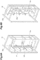
- the package exchanging device 7 collects the yarn supply bobbin B1 from the peg 24 and attaches the yarn supply package PI to the peg 24. As illustrated in FIG. 7 , the package exchanging device 7 runs along the second rail R2. The second rail R2 is laid on a floor and extends in the X direction (the arrangement direction of the creel stands 20). That is, the package exchanging device 7 runs along the X direction. The package exchanging device 7 moves between one end of the yarn supply unit 5 and the other end of the yarn supply unit 5 where the package replenishing device 6 is disposed.
- the package exchanging device 7 includes a running carrier 30 (running unit), an elevating unit 31, a holding unit 32, and an exchange unit 33. Further, the package exchanging device 7 includes a control unit 90 which controls the operation of each unit.
- the running carrier 30 includes a running base 30a and a column support portion 30b.
- the running base 30a has a rectangular parallelepiped shape.
- the running base 30a accommodates a wheel running along the second rail R2, a drive mechanism, and the like.
- the column support portion 30b is provided upright on the running base 30a.
- the column support portion 30b includes four second columns 30c, 30d, 30e, and 30f and a wall portion 30g.
- the second columns 30c to 30f and the wall portion 30g extend in the Z direction.
- the second column 30c is disposed at one end portion in the X direction and one end portion in the Y direction in the running base 30a.
- the second column 30c is disposed at a corner portion of the running base 30a.
- the second column 30d is disposed at one end portion in the X direction and the other end portion in the Y direction in the running base 30a.
- the second column 30c and the second column 30d are disposed at positions facing each other in the Y direction.
- the second column 30d is disposed at a corner portion of the running base 30a.
- the second column 30e is disposed at a position facing the second column 30c in the X direction so that a predetermined gap is formed with respect to the second column 30c.
- the second column 30f is disposed at the other end portion of the running base 30a in the Y direction between the second column 30c and the second column 30e in the X direction.
- the second column 30f is disposed so as to face the second column 30d in the X direction.
- the wall portion 30g extends in the X direction.
- the wall portion 30g is disposed at the other end portion in the X direction and the other end portion in the Y direction in the running base 30a. That is, the wall portion 30g is disposed at a corner portion of the running base 30a.
- the wall portion 30g is disposed so as to face the second column 30e in the Y direction and is disposed so as to face the second column 30f in the X direction.
- the elevating unit 31 moves up and down with the operator on board.
- the elevating unit 31 is used during maintenance or the like.
- the elevating unit 31 is disposed at the other end portion in the X direction in the running base 30a of the running carrier 30.
- the elevating unit 31 includes a guide portion 31a and an elevating portion 31b.
- the guide portion 31a is a guide rail.
- the guide portion 31a is disposed in the wall portion 30g of the column support portion 30b of the running carrier 30.
- the guide portion 31a extends in the Z direction.
- the elevating portion 31b is a working table on which the operator gets.
- the elevating portion 31b has a box shape.
- the elevating portion 31b is provided so as to be movable up and down in the Z direction along the guide portion 31a.
- the elevating portion 31b moves along the guide portion 31a by a drive mechanism (not illustrated).
- the holding unit 32 holds the plurality of (for example, four) yarn supply packages P1.
- the holding unit 32 holds the yarn supply packages PI as many as the yarn supply packages PI held by the package replenishing device 6.
- the holding unit 32 receives the yarn supply package PI supplied from the package replenishing device 6, temporarily stores the yarn supply package PI, and supplies the yarn supply package PI to the exchange unit 33.
- the holding unit 32 includes a main body frame 32a, a package support portion 32b, and a drive unit 32c.
- the main body frame 32a is disposed in the running base 30a of the running carrier 30.
- the main body frame 32a is disposed at one end portion of the running base 30a in the X direction.
- the package support portion 32b supports the yarn supply package P1.
- the package support portion 32b is provided so as to be rotatable.
- the package support portion 32b rotates in the range of about 90°.
- the package support portion 32b rotates between a replenishment position (see FIG. 8B ) in which the yarn supply package PI is supplied from the package replenishing device 6 and a supply position (see FIG. 8A ) in which the yarn supply package PI is supplied to the exchange unit 33.
- the drive unit 32c rotates the package support portion 32b.
- the drive unit 32c is, for example, an air cylinder.
- the exchange unit 33 exchanges the yarn supply bobbin B1 and the yarn supply package PI in the peg 24. Specifically, the exchange unit 33 collects the yarn supply bobbin B1 from the peg 24 and attaches the yarn supply package PI to the peg 24. As illustrated in FIG. 7 , the exchange unit 33 is provided adjacent to the holding unit 32. As illustrated in FIG. 9 , the exchange unit 33 includes a base 34, a rotation device 35, a collection device (exchange device) 40, a supply device (exchange device) 50, a yarn joining device 60, and a moving device 70.
- the base 34 supports the rotation device 35, the collection device 40, the supply device 50, and the yarn joining device 60.
- the base 34 is provided so as to be movable up and down along the column support portion 30b of the running carrier 30.
- the base 34 is provided at a position accessible to the holding unit 32.
- the rotation device 35 rotates the peg 24 of the creel stand 20.
- the rotation device 35 is fixed to the base 34.
- the rotation device 35 is disposed at a position facing the yarn supply unit 5 in the base 34.
- the rotation device 35 includes a first drive mechanism 36 and a second drive mechanism 37.
- the first drive mechanism 36 rotates the first peg 24a of the creel stand 20.
- the first drive mechanism 36 includes a first rotation driver 36a and a first rotation arm portion 36b.
- the first rotation driver 36a rotates the second wheel 26e of the first peg 24a.
- the first rotation driver 36a is a Geneva driver that constitutes a Geneva mechanism.
- the first rotation driver 36a rotates by the rotational driving of a motor (not illustrated).
- the first rotation arm portion 36b supports the first rotation driver 36a.
- the first rotation arm portion 36b is provided so as to be swingable in the horizontal direction.
- the first rotation arm portion 36b is driven by, for example, a motor or an air cylinder (not illustrated).
- the second drive mechanism 37 rotates the second peg 24b of the creel stand 20.
- the second drive mechanism 37 includes a second rotation driver 37a and a second rotation arm portion 37b.
- the second rotation driver 37a rotates the second wheel 26e of the second peg 24b.
- the second rotation driver 37a is a Geneva driver that constitutes a Geneva mechanism.
- the second rotation driver 37a rotates by the rotational driving of a motor (not illustrated).
- the second rotation arm portion 37b supports the second rotation driver 37a.
- the second rotation arm portion 37b is provided so as to be swingable in the horizontal direction.
- the second rotation arm portion 37b is driven by, for example, a motor or an air cylinder (not illustrated).
- the rotation device 35 changes the direction of the peg 24 by rotating the peg 24 when attaching the yarn supply package PI to the peg 24.
- the rotation device 35 operates the first drive mechanism 36 or the second drive mechanism 37 corresponding to the target peg 24.
- the rotation device 35 swings the first rotation arm portion 36b so that the first rotation driver 36a engages with the second wheel 26e of the first peg 24a.
- the rotation device 35 rotates the first rotation driver 36a in one direction when the first rotation driver 36a engages with the second wheel 26e.
- the rotation transmitting member 26b rotates. Accordingly, the peg 24 rotates so that the front end portions of the package support members 25a and 25b face the exchange unit 33.
- the collection device 40 collects the yarn supply bobbin B1 to which the adapter 10 is attached from the peg 24. As illustrated in FIG. 10 , the collection device 40 includes a first support mechanism 41 and a first collection drive mechanism 42.
- the first support mechanism 41 supports the yarn supply bobbin B1. Further, the first support mechanism 41 moves forward and backward with respect to the peg 24 so as to collect the yarn supply bobbin B1.
- the first support mechanism 41 includes a first slide portion 41a and a first package support member 41b.
- the first slide portion 41a includes a first linear guide 41c. A part of the first slide portion 41a can move in a predetermined direction through the first linear guide 41c.
- the first package support member 41b supports the yarn supply bobbin B1.
- the first package support member 41b is provided in a front end portion of the moving first slide portion 41a.
- the first package support member 41b extends in the extending direction of the first slide portion 41a.
- the first collection drive mechanism 42 drives the first support mechanism 41.
- the first collection drive mechanism 42 includes a first slide rail 42a, a first collection drive unit 42b, a first elevating portion 42c, and a second collection drive unit 42d.
- the first slide rail 42a is connected to the first slide portion 41a.
- the first slide rail 42a moves a part of the first slide portion 41a in a reciprocating manner by the driving of the first collection drive unit 42b.
- the first collection drive unit 42b is, for example, an air cylinder.
- the first elevating portion 42c is connected to the first slide portion 41a.
- the first elevating portion 42c moves the first slide portion 41a up and down by the driving of the second collection drive unit 42d. Accordingly, the first slide portion 41a swings.
- the second collection drive unit 42d is, for example, a motor.
- a collection operation of the yarn supply bobbin B1 by the collection device 40 will be described.
- the collection device 40 advances a part of the first slide portion 41a of the first support mechanism 41 by the first collection drive mechanism 42 with respect to the peg 24 rotated by the rotation device 35 so that the first package support member 41b is located in the hollow portion of the yarn supply bobbin B1.
- the collection device 40 swings the first slide portion 41a of the first support mechanism 41 downward by the first collection drive mechanism 42 so that the first package support member 41b is inclined with respect to the horizontal direction.
- the collection device 40 swings the first slide portion 41a upward by the first collection drive mechanism 42 so that the first package support member 41b becomes horizontal.
- the first package support member 41b contacts the yarn supply bobbin B1 so that the yarn supply bobbin B1 is lifted and the yarn supply bobbin B1 is separated from the package support members 25a and 25b.
- the collection device 40 retracts a part of the first slide portion 41a of the first support mechanism 41 by the first collection drive mechanism 42. As described above, the collection device 40 collects the yarn supply bobbin B1 from the peg 24.
- the supply device 50 supplies the yarn supply package PI to the peg 24.
- the supply device 50 includes a second support mechanism 51 and a second supply drive mechanism 52.
- the second support mechanism 51 supports the yarn supply package P1. Further, the second support mechanism 51 moves forward and backward with respect to the peg 24 so as to supply the yarn supply package P1.
- the second support mechanism 51 includes a second slide portion 51a and a second package support member 51b.
- the second slide portion 51a includes a second linear guide 51c. A part of the second slide portion 51a can move in a predetermined direction through the second linear guide 51c.
- the second package support member 51b supports the yarn supply package P1.
- the second package support member 51b is provided in the front end portion of the moving second slide portion 51a.
- the second package support member 51b extends in the extending direction of the second slide portion 51a.
- the second supply drive mechanism 52 drives the second support mechanism 51.
- the second supply drive mechanism 52 includes a second slide rail 52a, a first supply drive unit 52b, a second elevating portion 52c, and a second supply drive unit 52d.
- the second slide rail 52a is connected to the second slide portion 51a.
- the second slide rail 52a moves a part of the second slide portion 51a in a reciprocating manner by the driving of the first supply drive unit 52b.
- the first supply drive unit 52b is, for example, an air cylinder.
- the second elevating portion 52c is connected to the second slide portion 51a.
- the second elevating portion 52c moves the second slide portion 51a up and down by the driving of the second supply drive unit 52d. Accordingly, the second slide portion 51a swings.
- the second supply drive unit 52d is, for example, a motor.
- the supply device 50 acquires the yarn supply package PI from the holding unit 32 when the package exchanging device 7 moves.
- the supply device 50 advances a part of the second slide portion 51a of the second support mechanism 51 by the second supply drive mechanism 52 with respect to the yarn supply package PI supported by the package support portion 32b of the holding unit 32 so that the second package support member 51b is located in the hollow portion of the yarn supply package P1.
- the supply device 50 swings the second slide portion 51a of the second support mechanism 51 downward by the second supply drive mechanism 52 so that the second package support member 51b is inclined with respect to the horizontal direction.
- the supply device 50 swings the second slide portion 51a upward by the second supply drive mechanism 52 so that the second package support member 51b becomes horizontal. Accordingly, the second package support member 51b contacts the yarn supply package PI so that the yarn supply package PI is lifted and the yarn supply package PI is separated from the package support portion 32b.
- the supply device 50 retracts a part of the second slide portion 51a of the second support mechanism 51 by the second supply drive mechanism 52. As described above, the supply device 50 acquires the yarn supply package PI from the holding unit 32.
- a supply operation in which the supply device 50 supplies the yarn supply package PI to the peg 24 will be described.
- the supply device 50 advances a part of the second slide portion 51a of the second support mechanism 51 by the second supply drive mechanism 52 with respect to the peg 24 from which the yarn supply bobbin B1 is separated so that the package support members 25a and 25b of the peg 24 are located in the hollow portion of the yarn supply package P1.
- the supply device 50 swings the second slide portion 51a downward by the second supply drive mechanism 52 so that the second package support member 51b is inclined with respect to the horizontal direction.
- the package support members 25a and 25b of the peg 24 contact the yarn supply package PI so that the yarn supply package PI is supported by the peg 24 and the second package support member 51b is separated from the yarn supply package P1.
- the supply device 50 retracts a part of the second slide portion 51a of the second support mechanism 51 by the second supply drive mechanism 52. As described above, the supply device 50 attaches the yarn supply package PI to the peg 24.
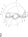
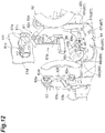
- the yarn joining device 60 joins the yarn Y of the yarn supply package PI supported by the first peg 24a and the yarn Y of the yarn supply package PI supported by the second peg 24b. As illustrated in FIGS. 12 , 13 , and 14 , the yarn joining device 60 includes a catching and guiding mechanism (a guide device) 61, a first rotation mechanism 62, a second rotation mechanism 63, and a yarn joining mechanism 64.
- the yarn joining device 60 is provided so as to be movable by a movement mechanism (not illustrated) in a direction (the Y direction) in which the exchange unit 33 faces the yarn supply unit 5.
- the yarn joining device 60 moves between a standby position in which the yarn joining device 60 is disposed in the base 34 and a yarn joining position in which the yarn joining device 60 moves toward the yarn supply unit 5 so as to advance outward in relation to the base 34.
- the catching and guiding mechanism 61 catches the yarn Y of the yarn supply package PI and guides the yarn Y to the yarn joining mechanism 64.
- the catching and guiding mechanism 61 catches the first yarn end Y1 of the yarn Y of the yarn supply package PI supported by one peg 24 and the second yarn end Y2 of the yarn Y of the yarn supply package PI supported by the other peg 24 and guides the yarns to the yarn joining mechanism 64.
- the catching and guiding mechanism 61 includes a suction portion 61a and a yarn joining arm portion 61b.
- the suction portion 61a sucks and catches the yarn Y
- the suction portion 61a includes a suction pipe 61c, a suction nozzle 61d, and a hook portion 61e.
- the suction nozzle 61d is provided in the front end portion of the suction pipe 61c.
- the suction nozzle 61d sucks the yarn Y
- a negative pressure source (not illustrated) is connected to the suction pipe 61c. Accordingly, a suction flow is generated in the suction nozzle 61d.
- the base end side of the suction pipe 61c is connected to the yarn joining arm portion 61b.
- the hook portion 61e is provided at a position facing the suction nozzle 61d and the front end portion of the suction pipe 61c.
- the hook portion 61e locks the yarn Y entangled by the yarn joining device 60.
- the yarn joining arm portion 61b moves the suction portion 61a.
- the yarn joining arm portion 61b includes a link mechanism and a plurality of motors.
- the yarn joining arm portion 61b is supported by a bracket 61f.
- Each of the first rotation mechanism 62 and the second rotation mechanism 63 operates the peg 24 so as to rotate the yarn supply package P1.
- Each of the first rotation mechanism 62 and the second rotation mechanism 63 rotates the yarn supply package PI so that the yarn Y is fed from the yarn supply package PI when guiding the yarn Y to the yarn joining mechanism 64 by the catching and guiding mechanism 61.
- the first rotation mechanism 62 operates the first peg 24a.
- the first rotation mechanism 62 includes a first yarn joining driver 62a, a first motor 62b, and a first yarn joining arm portion 62c.
- the first yarn joining driver 62a is rotatably and axially supported by the first yarn joining arm portion 62c.
- the first yarn joining driver 62a is provided with a first driven pulley 62d.
- the first motor 62b is fixed to the first yarn joining arm portion 62c.
- a first drive pulley 62e is connected to the output shaft of the first motor 62b.
- the first motor 62b drives the first drive pulley 62e so as to rotate about an axis.
- a first power transmission belt 62f is stretched over the first driven pulley 62d and the first drive pulley 62e. Accordingly, the first yarn joining driver 62a rotates by the rotational driving of the first motor 62b.
- the second rotation mechanism 63 operates the second peg 24b.
- the second rotation mechanism 63 includes a second yarn joining driver 63a, a second motor 63b, and a second yarn joining arm portion 63c.
- the second yarn joining driver 63a is rotatably and axially supported by the second yarn joining arm portion 63c.
- the second yarn joining driver 63a is provided with a second driven pulley 63d.
- the second motor 63b is fixed to the second yarn joining arm portion 63c.
- the second drive pulley 63e is connected to the output shaft of the second motor 63b.
- the second motor 63b drives the second drive pulley 63e so as to rotate around a shaft.
- a second power transmission belt 63f is stretched over the second driven pulley 63d and the second drive pulley 63e. Accordingly, the second yarn joining driver 63a rotates by the rotational driving of the second motor 63b.
- the yarn joining mechanism 64 performs a yarn joining operation.
- the yarn joining mechanism 64 includes a splicer 66, a first guide mechanism 67, and a second guide mechanism 68.
- the splicer 66 includes a yarn joining portion 66a and a pair of sandwiching mechanisms 66b and 66c.
- the yarn joining portion 66a entangles the yarn Y of the yarn supply package PI supported by the first peg 24a and the yarn Y of the yarn supply package PI supported by the second peg 24b.
- the sandwiching mechanisms 66b and 66c are provided at positions sandwiching the yarn joining portion 66a.
- the sandwiching mechanisms 66b and 66c sandwich the yarn Y inserted into the chamber of the yarn joining portion 66a.
- the first guide mechanism 67 locks and guides the yarn Y.
- the first guide mechanism 67 includes a first hook 67a, a second hook 67b, and a third hook 67c.
- the first hook 67a, the second hook 67b, and the third hook 67c are provided so as to be swingable.
- the first hook 67a is provided with a potentiometer (not illustrated) that detects a tension of the yarn Y.
- the yarn joining device 60 controls the operation of the first motor 62b of the first rotation mechanism 62 on the basis of the detection result of the potentiometer. That is, the yarn joining device 60 draws the yarn Y from the yarn supply package PI at a predetermined tension by adjusting the rotation amount (feed amount) of the yarn supply package P1 on the basis of the detection result of the potentiometer.
- the second guide mechanism 68 locks and guides the yarn Y
- the second guide mechanism 68 includes a first hook 68a, a second hook 68b, and a third hook 68c.
- the first hook 68a, the second hook 68b, and the third hook 68c are provided so as to be swingable.
- the first hook 68a is provided with a potentiometer (not illustrated) which detects the tension of the yarn Y
- the yarn joining device 60 controls the operation of the second motor 63b of the second rotation mechanism 63 on the basis of the detection result of the potentiometer. That is, the yarn joining device 60 adjusts the rotation amount (feed amount) of the yarn supply package P1 on the basis of the detection result of the potentiometer and draws the yarn Y from the yarn supply package PI with a predetermined tension.
- a yarn joining operation of the yarn joining device 60 will be described. Specifically, an example of a case in which the yarn joining device 60 joins the first yarn end Y1 on the outer layer side of the yarn supply package PI supported by the first peg 24a and the second yarn end Y2 on the inner layer side of the yarn supply package PI supported by the second peg 24b will be described.
- the yarn joining device 60 When the yarn joining operation starts, the yarn joining device 60 operates the first peg 24a by the first rotation mechanism 62 and operates the second peg 24b by the second rotation mechanism 63 so that the adapter 10 is rotated to a position in which the first yarn end Y1 and the second yarn end Y2 can be caught by the suction portion 61a as illustrated in FIG. 14 .
- the first yarn joining driver 62a is engaged with the first wheel 25j of the first peg 24a and the first motor 62b is driven to rotate the first yarn joining driver 62a.
- the second yarn joining driver 63a is engaged with the first wheel 25j of the second peg 24b and the second motor 63b is driven to rotate the second yarn joining driver 63a.
- the yarn supply package PI supported by each of the first peg 24a and the second peg 24b rotates, so that the adapter 10 rotates.
- the yarn joining device 60 detects a detection object (not illustrated) provided in the adapter 10 by a sensor (not illustrated) and controls the first motor 62b and the second motor 63b on the basis of the detection result of the sensor so that the adapter 10 is rotated to a predetermined position.
- the yarn joining device 60 When the adapter 10 is rotated, the yarn joining device 60 operates the yarn joining arm portion 61b of the catching and guiding mechanism 61 so that the suction portion 61a catches the first yarn end Y1 from the adapter 10 of the yarn supply package PI supported by the first peg 24a and catches the second yarn end Y2 from the adapter 10 of the yarn supply package PI supported by the second peg 24b. At this time, the yarn joining device 60 operates the first peg 24a by the first rotation mechanism 62 and operates the second peg 24b by the second rotation mechanism 63 so that the yarn supply package PI is rotated. Accordingly, the yarn Y is drawn out from the yarn supply package PI at a predetermined tension.
- the yarn joining device 60 allows the suction portion 61a to hook the yarn Y having the first yarn end Y1 on the first guide mechanism 67 and guide the yarn Y to the splicer 66 and to hook the yarn Y having the second yarn end Y2 on the second guide mechanism 68 and guide the yarn Y to the splicer 66.
- the yarn joining device 60 performs the yarn joining operation of the splicer 66. Accordingly, the yarn joining device 60 joins the first yarn end Y1 on the outer layer side of the yarn supply package PI supported by the first peg 24a and the second yarn end Y2 on the inner layer side of the yarn supply package PI supported by the second peg 24b.
- the moving device 70 rotationally moves the collection device 40, the supply device 50, and the yarn joining device 60.
- the moving device 70 moves each of the collection device 40, the supply device 50, and the yarn joining device 60 to a work position for the peg 24. Further, the moving device 70 moves the collection device 40 and the supply device 50 to a work position for the holding unit 32.
- the moving device 70 includes a rotation support portion 71 and an exchange unit driving unit 72.
- the rotation support portion 71 supports the collection device 40, the supply device 50, and the yarn joining device 60.
- the rotation support portion 71 is provided in the base 34 so as to be rotatable around a rotation shaft extending in the vertical direction.
- the rotation support portion 71 supports the collection device 40, the supply device 50, and the yarn joining device 60 so that the collection device 40, the supply device 50, and the yarn joining device 60 are respectively disposed in three different directions when viewed from the direction of the rotation shaft of the rotation support portion 71.
- the rotation support portion 71 includes a wheel (not illustrated).
- the wheel is a Geneva wheel that constitutes a Geneva mechanism.
- the exchange unit driving unit 72 rotates the rotation support portion 71.
- the exchange unit driving unit 72 is a Geneva driver that constitutes a Geneva mechanism.
- the exchange unit driving unit 72 rotates by the rotational driving of a motor (not illustrated). In the moving device 70, the rotation support portion 71 rotates by the driving of the exchange unit driving unit 72.
- the moving device 70 stops the rotation support portion 71 at seven positions.
- the moving device 70 stops the rotation support portion 71 at a position in which the collection device 40 collects the yarn supply bobbin B1 from the first peg 24a, a position in which the collection device 40 collects the yarn supply bobbin B1 from the second peg 24b, a position in which the supply device 50 supplies the yarn supply package PI to the first peg 24a, a position in which the supply device 50 supplies the yarn supply package PI to the second peg 24b, a position in which the yarn joining device 60 performs a yarn joining operation, a position in which the supply device 50 acquires the yarn supply package PI from the holding unit 32, and a position in which the collection device 40 supplies the yarn supply bobbin B1 to the holding unit 32.
- the running carrier 30 which is one of characteristic parts of an aspect of the invention will be described in more detail below.
- the second column 30c and the second column 30d of the running carrier 30 is provided with a sensor 131 (an acquisition unit) which acquires the remaining amount of the yarn Y wound on the yarn supply package PI supported by the peg 24 of the creel stand 20.
- the plurality of sensors 131 are provided in the vertical direction (the Z direction).
- the sensors 131 are provided as many as the pegs 24 arranged in the creel stand 20 in the vertical direction.
- eights pegs 24 are arranged in the creel stand 20 in the vertical direction.
- eight sensors 131 are arranged in each of the second column 30c and the second column 30d in the vertical direction.
- Eight sensors 131 are disposed in each of the second column 30c and the second column 30d so as to correspond to the height positions where the peg 24 is fixed to the creel stand 20.
- the sensor 131 detects a distance to an outer peripheral surface S of the yarn supply package PI in the radial direction of the yarn supply package P1.
- the sensor 131 emits a detection medium (for example, light) in a direction along the radial direction of the yarn supply package PI so that the outer peripheral surface S of the yarn supply package PI is irradiated with the detection medium.
- the sensor 131 is, for example, a photoelectric sensor. More specifically, the sensor 131 is an analog sensor which outputs a signal according to a distance to the outer peripheral surface S of the yarn supply package P1.
- the sensor 131 is provided in the running carrier 30 which moves substantially in parallel to the arrangement direction of the creel stands 20 (the X direction). For this reason, a distance between a measurement position in the X direction set in advance for each yarn supply package PI and a center (that is, the yarn supply bobbin B1) of the yarn supply package PI is constant at all times. Accordingly, when a distance to the outermost layer of the yarn Y (that is, the outer peripheral surface S) wound around the yarn supply bobbin B1 is measured, the diameter of the yarn Y wound around the yarn supply bobbin B1 (that is, the remaining amount of the yarn Y in the yarn supply package PI) can be derived. In this embodiment, the remaining amount of the yarn Y wound on the yarn supply package PI is derived by deriving a distance to the outer peripheral surface S of the yarn supply package P1 on the basis of a signal output from the analog sensor 131.
- the yarn supply package PI which supplies the yarn Y to the false-twisting machine 2 is disposed so as to be inclined from the X direction. Specifically, a pair of two yarn supply packages PI is disposed so as to face each other slightly inward. When viewed from above, extension lines Ar1 and Ar1 obtained by extending the rotation shafts of the pair of two yarn supply packages PI are disposed so as to intersect each other in a direction in which the false-twisting machine 2 is disposed (a direction in which the running carrier 30 is disposed).
- the sensor 131 disposed in the second column 30c is provided so as to acquire a distance to the outer peripheral surface S of one of the pair of two yarn supply packages PI and the sensor 131 disposed in the second column 30d is provided so as to acquire a distance to the outer peripheral surface S of the other of the pair of two yarn supply packages P1.
- the sensor 131 disposed in the second column 30c and the sensor 131 disposed in the second column 30d are provided in a direction in which the emission directions Ar2 and Ar2 of the detection medium intersect a direction in which the false-twisting machine 2 is disposed (a direction in which the running carrier 30 is disposed).
- the remaining amount of the yarn Y in the plurality of yarn supply packages PI supported by the creel stands 20 is acquired in such a manner that the running carrier 30 runs along the creel stand 20. That is, the remaining amount of the yarn Y in each yarn supply package PI is acquired on the basis of a distance to the outer peripheral surface S of the yarn supply package PI acquired by the sensor 131 when the running carrier 30 moves from one end to the other end of the creel stand 20.
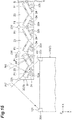
- the running carrier 30 moves leftward along the creel stand 20 and acquires the remaining amount of the yarn Y in one of the yarn supply packages PI disposed as a pair (a pair of yarn supply packages PI) at the left end of the creel stand 20 by the sensor 131 disposed in the second column 30c as illustrated in FIG. 15 .
- the running carrier 30 moves rightward and acquires the remaining amount of the yarn Y in one of the yarn supply packages PI disposed as a second pair from the left end by the sensor 131 disposed in the second column 30c.
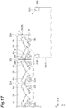
- the running carrier 30 moves rightward and acquires the remaining amount of the yarn Y in the other of the yarn supply packages PI as a pair of the left end of the creel stand 20 by the sensor 131 disposed in the second column 30d as illustrated in FIG. 16 .
- the running carrier 30 moves rightward and acquires the remaining amount of the yarn Y of the other of the yarn supply packages PI disposed as a second pair from the left end of the creel stand 20 by the sensor 131 disposed in the second column 30d.
- the running carrier 30 moves rightward along the creel stand 20 while repeating the running of the running carrier 30 and the acquiring of the sensor 131 and acquires the remaining amount of the other of the yarn supply packages PI disposed as a pair of the right end of the creel stand 20 by the sensor 131 disposed in the second column 30d. With such a series of operations, the remaining amount of the yarn Y in all yarn supply packages PI supported by the creel stands 20 is acquired (sensed).
- the control unit 90 is an electronic control unit including a central processing unit (CPU), a read only memory (ROM), a random access memory (RAM), an I/O port, a communication port, and the like.
- the ROM stores a program for controlling each of components.
- each of the functions of the prediction unit 90a and the running control unit 90b described in the subsequent stage illustrated in FIG. 18 is executed under the control of the CPU by reading a predetermined computer software onto hardware such as a CPU and a main memory.
- the prediction unit 90a predicts a timing at which the yarn Y disappears from the yarn supply package PI on the basis of the remaining amount of the yarn Y in the yarn supply package PI acquired by the sensor 131. In this embodiment, the prediction unit 90a predicts a timing at which the yarn Y disappears on the basis of a distance to the outer peripheral surface S of the yarn supply package PI detected by the sensor 131.
- the timing at which the yarn Y disappears mentioned herein includes the time required until the yarn Y is completely drawn out from the yarn supply package PI and disappears and the time when the yarn Y is completely drawn out from the yarn supply package PI and disappears.
- the prediction unit 90a of this embodiment receives an analog signal from the sensor 131 and analyzes the analog signal so as to derive a distance from the sensor 131 to the outer peripheral surface S of the yarn supply package P1. Next, the prediction unit 90a derives the remaining amount of the yarn Y in the yarn supply package PI, for example, on the basis of a corresponding relationship or the like between the remaining amount of the yarn Y in the yarn supply package PI and the distance stored in a storage unit (not illustrated).
- the prediction unit 90a predicts a timing at which the yarn Y disappears from the yarn supply package P1 on the basis of, for example, the yarn supply amount per unit time stored in the storage unit (the wound amount per unit time in the winding package P2) and the remaining amount of the yarn Y in the yarn supply package P1. Additionally, the method of deriving the timing at which the yarn Y disappears is not limited to the above-described contents.
- the running control unit 90b controls the running of the running carrier 30.
- the running control unit 90b moves the running carrier 30 so that the remaining amount of the yarn Y in all yarn supply packages PI held by the creel stands 20 is acquired at a predetermined time interval. Further, the running control unit 90b moves the running carrier 30 to the exchange position of the yarn supply package PI which is predicted that the yarn Y disappears on the basis of the timing at which the yarn Y disappears from the yarn supply package PI and which is predicted by the prediction unit 90a.
- an overall control device 95 which controls the entire false-twisting system 1 including the false-twisting machine 2, the first transporting device 3, the second transporting device 4, the package replenishing device 6, and the package exchanging device 7 will be described as one of characteristic parts of an aspect of the invention.
- the overall control device 95 is an electronic control unit including a CPU, a ROM, a RAM, an I/O port, a communication port, and the like.
- the ROM stores a program for controlling each of components. Further, each of the functions of the determination unit 95a described in the subsequent stage illustrated in FIG. 18 is executed under the control of the CPU by reading a predetermined computer software on hardware such as a CPU and a main memory.
- the overall control device 95 may include a display unit 95b such as a display that displays various kinds of information.
- the determination unit 95a determines whether or not the yarn joining portion is included in the winding package P2 on the basis of the prediction result of the prediction unit 90a.
- the yarn joining portion starts the movement (feed) toward the winding package P2 from a timing at which the yarn Y disappears in the yarn supply package P1.
- a time at which the yarn Y disappears in the yarn supply package PI is derived, it is possible to derive a certain timing at which the yarn is wound as the winding package P2 on the basis of the winding speed or the like of the winding package P2.
- the determination unit 95a of this embodiment derives a timing at which the yarn joining portion is wound on the winding package P2 on the basis of the timing at which the yarn Y disappears from the yarn supply package PI and which is predicted by the prediction unit 90a and the winding speed of the winding package P2 stored in the storage unit (not illustrated) or the like.
- the timing at which the yarn joining portion is wound on the winding package mentioned herein includes a time required until the yarn joining portion is wound on the winding package and a time when the yarn joining portion is wound on the winding package.
- the overall control device 95 manages a time at which the winding bobbin B2 of the winding package P2 is set and a time at which the winding package P2 is discharged.
- the determination unit 95a determines whether or not the yarn joining portion is included in each winding package P2 on the basis of the previous management information and the timing at which the yarn joining portion is wound on the winding package P2.
- a result for example, information of the winding package P2 having the yarn joining portion
- the information of the winding package P2 having the yarn joining portion may be transmitted to a terminal device 97 which is provided so as to communicate with the overall control device 95 and is carried by an operator or the like.
- the prediction result of the prediction unit 90a transmitted from the control unit 90 may be displayed on the display unit 95b.
- the display unit 95b may display a list of the time required until the yarn Y is completely drawn out from the yarn supply package PI and disappears and the time when the yarn Y is completely drawn out from the yarn supply package PI and disappears for each yarn supply package PI held by the creel stand 20.
- the list may be disposed on the terminal device 97. Additionally, the terminal device 97 may directly receive information on the time required until the yarn Y is completely drawn out from the yarn supply package PI and disappears and the time when the yarn Y is completely drawn out from the yarn supply package PI and disappears from the control unit 90 without using the overall control device 95.
- the package exchanging system 100 (see FIG. 18 ) that predicts a timing at which the yarn Y disappears from the yarn supply package PI is constructed by the running carrier 30, the sensor 131, the prediction unit 90a, the running control unit 90b, and the overall control device 95.
- the package exchanging system 100 of the above-described embodiment since the remaining amount of the yarn Y wound on the yarn supply package PI is acquired at the time of performing the sensing, it is possible to check the state of the yarn supply package PI in more detail as compared with a case in which the state of the yarn Y is acquired in three stages. Further, in the package exchanging system 100 with this configuration, since a timing at which the yarn Y disappears from the yarn supply package PI is predicted on the basis of the acquired remaining amount of the yarn Y in the yarn supply package PI, it is possible to check the state of the yarn supply package PI at all times regardless of the sensing timing. As a result, it is possible to more efficiently perform the yarn joining operation and the exchange operation of the yarn supply package P1.
- the sensor 131 is a sensor that detects a distance to the outer peripheral surface S of the yarn supply package PI in the radial direction of the yarn supply package PI and the prediction unit 90a predicts a timing at which the yarn Y disappears from the yarn supply package P1 on the basis of the distance detected by the sensor 131. For this reason, it is possible to acquire the position of the outermost layer (the outer peripheral surface S) of the yarn supply package PI, that is, the diameter of the yarn supply package PI with a simple configuration. Since the diameter of the yarn supply package PI can be acquired, it is possible to predict the remaining amount of the yarn Y in the yarn supply package PI by a simple calculation.
- the running control unit 90b moves the running carrier 30 so that the remaining amount of the yarn Y in all yarn supply packages PI held by the creel stands 20 are acquired at a predetermined time interval. For this reason, since the remaining amount of the yarn Y in the yarn supply package PI is acquired at a predetermined time interval, it is possible to more accurately predict a timing at which the yarn Y disappears from the yarn supply package P1.
- the running carrier 30 includes the yarn joining device 60 which connects the yarn ends Y1 and Y2 of the yarn supply package PI, the catching and guiding mechanism 61 which guides the yarn ends Y1 and Y2 of the yarn supply package PI to the yarn joining device 60, the supply device 50 which supplies the yarn supply package PI to the creel stand 20, and the collection device 40 which collects the yarn supply bobbin B1 from the creel stand 20.
- the yarn joining operation and the exchange operation of the yarn supply package PI can be performed by the running carrier 30 without using human hands.
- the running control unit 90b moves the running carrier 30 to an exchange position of the yarn supply package PI in which the yarn Y is predicted to disappear on the basis of a timing at which the yarn Y disappears from the yarn supply package PI and which is predicted by the prediction unit 90a. For this reason, the yarn joining operation and the exchange operation of the yarn supply package PI can be more efficiently performed.
- the prediction unit 90a and the running control unit 90b are provided in the running carrier 30. For this reason, the package exchanging system 100 can be provided as the running carrier 30.
- the package exchanging system 100 of the above-described embodiment separately includes the determination unit 95a which determines whether or not the yarn joining portion is included in the winding package P2 on the basis of the prediction result of the prediction unit 90a. For this reason, it is possible to easily select the high-grade winding package P2.
- the invention is not limited thereto.
- a configuration of the package exchanging system 100 in which the prediction unit 90a and the running control unit 90b are mounted on the running carrier 30 without the function of the determination unit 95a may be employed.
- a configuration of the package exchanging system 100 in which all of the prediction unit 90a, the running control unit 90b, and the determination unit 95a are mounted on the running carrier 30 may be employed.
- the package exchanging system 100 can be provided as the running carrier.
- the package exchanging system 100 may have a configuration in which all or any one of the prediction unit 90a, the running control unit 90b, and the determination unit 95a may be mounted on not the running carrier 30 but a control device, a server device, or the like provided so as to communicate with the running carrier 30.
- the running carrier 30 provided with the sensor 131 may be the running carrier 30 which is not provided with any one of the yarn joining device 60, the catching and guiding mechanism 61, the supply device 50, and the collection device 40, but is provided with a working table on which an operator who performs the yarn joining operation and the exchange operation of the yarn supply package PI gets.
- the running carrier 30 provided with the sensor 131 may be the running carrier 30 provided with any one of the yarn joining device 60, the catching and guiding mechanism 61, the supply device 50, and the collection device 40.
- the running carrier 30 having a vehicle wheel has been described as an example of the running unit, but may be a running unit having a linear motion mechanism instead of the vehicle wheel.
- the analog sensor 131 has been described as an example of the acquisition unit that acquires the remaining amount of the yarn Y wound on the yarn supply package PI, but an aspect of the invention is not limited thereto.
- an imaging device capable of capturing an image of the outer peripheral surface of the yarn supply package PI may be provided and an image caught by the imaging device may be analyzed so as to acquire the remaining amount of the yarn Y wound on the yarn supply package P1.
- the sensors 131 are provided in the running carrier 30 as many as the pegs 24 arranged in the creel stands 20 in the vertical direction, but an aspect of the invention is not limited thereto.
- one or more sensors 131 may be provided in the running carrier 30 so as to be movable up and down. Also in this case, it is possible to acquire the remaining amount of the yarn Y in all yarn supply packages PI held by the creel stands 20.
Landscapes
- Engineering & Computer Science (AREA)
- Textile Engineering (AREA)
- Quality & Reliability (AREA)
- Replacing, Conveying, And Pick-Finding For Filamentary Materials (AREA)
- Spinning Or Twisting Of Yarns (AREA)
Abstract
Description
- An aspect of the invention relates to a package exchanging system.
- A false-twisting machine which false-twists a plurality of synthetic yarns supplied from a yarn supply package and winds the processed synthetic yarn in a winding device so as to form a winding package is known (for example, Patent Literature 1; Japanese Unexamined Patent Publication No.
H6-200434 - In such a configuration, when the synthetic yarn of the yarn supply package disappears, there is a need to supply a new package and to join the synthetic yarn of the yarn supply package supported by one peg and the synthetic yarn of the yarn supply package supported by the other peg. Such a yarn joining operation (tail joining operation) is generally performed through human hands. Patent Literature 2 (Japanese Examined Patent Publication No.
H7-68010 -
Patent Literature 2 discloses a package exchanging system (a yarn exchanging system) in which the working carrier is provided with a sensor for detecting the diameter of the yarn supply package held by the creel stand in three stages (full, half, and small). Accordingly, since the operator can determine that the exchange is not necessary in the full case, the exchange is soon necessary in the half case, and the exchange is necessary in the small case, it is possible to efficiently perform the yarn joining operation and the exchange operation of the yarn supply package held by the creel stand. - However, in the conventional package exchanging system, the state of the yarn supply package can be determined only at the moment (sensing moment) detected by the sensor provided in the working carrier. For this reason, there is a case in which the synthetic yarn of the yarn supply package disappears without acquiring a state in which the synthetic yarn of the yarn supply package is likely to disappear when the sensing interval time is long.
- Here, an object of an aspect of the invention is to provide a package exchanging system capable of more efficiently performing a yarn joining operation and an exchange operation of a yarn supply package.
- A package exchanging system according to an aspect of the invention is a package exchanging system used in a textile machine including a creel stand allowing a yarn supply package support portion to support a yarn supply package in which a synthetic yarn formed of a synthetic fiber is wound around a bobbin, a processing device processing the synthetic yarn supplied from the yarn supply package, and a winding device forming a winding package by winding the processed synthetic yarn, the package exchanging system including: a running unit which is provided so as to be movable in one direction along the creel stand disposed in the one direction; a running control unit which controls the running of the running unit; an acquisition unit which is provided in the running unit and acquires a remaining amount of the synthetic yarn wound on the yarn supply package held by the creel stand; and a prediction unit which predicts a timing at which the synthetic yarn disappears from the yarn supply package on the basis of the remaining amount of the synthetic yarn acquired by the acquisition unit.
- In the package exchanging system with this configuration, since the remaining amount of the yarn wound on the yarn supply package is acquired at the time of sensing, it is possible to more specifically check the state of the yarn supply package as compared with a case in which the state of the yarn is acquired in three stages. Further, in the package exchanging system with this configuration, since a timing at which the yarn disappears from the yarn supply package is predicted on the basis of the acquired remaining amount of the yarn, it is possible to check the state of the yarn supply package at all times regardless of the sensing timing. As a result, it is possible to more efficiently perform the yarn joining operation and the exchange operation of the yarn supply package.
- In the package exchanging system according to an aspect of the invention, the acquisition unit may be a sensor that detects a distance to an outer peripheral surface of the package in a radial direction of the package and the prediction unit may predict a timing at which the synthetic yarn disappears from the package on the basis of the distance detected by the sensor. In this configuration, it is possible to acquire the position of the outermost layer of the package, that is, the diameter of the package with a simple configuration. When the diameter of the package can be acquired, the remaining amount of the yarn can be predicted by a simple calculation.
- In the package exchanging system according to an aspect of the invention, the running control unit may move the running unit so that the distance of all yarn supply packages held by the creel stands is acquired at a predetermined time interval. In this configuration, since the remaining amount of the yarn is acquired at a predetermined time interval, it is possible to more accurately predict a timing at which the yarn disappears from the yarn supply package.
- In the package exchanging system according to an aspect of the invention, the running unit may include a yarn joining device which connects yarn ends of the yarn supply packages, a guide device which guides the yarn end of the yarn supply package to the yarn joining device, and an exchange device which supplies the yarn supply package to the creel stand and collects the bobbin from the creel stand. Accordingly, it is possible to perform the yarn joining operation and the exchange operation of the yarn supply package by the running unit without using human hands.
- In the package exchanging system according to an aspect of the invention, the running control unit may move the running unit to an exchange position of the yarn supply package predicted that the synthetic yarn disappears on the basis of the timing predicted by the prediction unit. Accordingly, it is possible to more efficiently perform the yarn joining operation and the exchange operation of the yarn supply package.
- In the package exchanging system according to an aspect of the invention, the prediction unit and the running control unit may be provided in the running unit. In this configuration, the package exchanging system can be provided as the running unit.
- The package exchanging system according to an aspect of the invention may further include a determination unit which determines whether or not a yarn joining portion is included in the winding package on the basis of a prediction result of the prediction unit. Here, there is a case in which a grade (rank) is classified depending on whether or not the yarn joining portion is included in the synthetic yarn wound as the winding package. In this configuration, the high-grade winding package can be simply selected.
- According to an aspect of the invention, it is possible to more efficiently perform the yarn joining operation and the exchange operation of the yarn supply package.
-
-
FIG. 1 is a diagram illustrating a configuration of a false-twisting system according to an embodiment. -
FIG. 2 is a perspective view illustrating a package holding unit of a first transporting device. -
FIG. 3 is a perspective view illustrating a yarn supply package to which an adapter is attached. -
FIG. 4 is a perspective view illustrating a package holding unit of a second transporting device. -
FIG. 5 is a perspective view illustrating a creel stand. -
FIG. 6 is a perspective view illustrating a peg. -
FIG. 7 is a perspective view illustrating a package exchanging device. -
FIGS. 8A and 8B are perspective views illustrating a holding unit. -
FIG. 9 is a diagram illustrating a configuration of an exchange unit. -
FIG. 10 is a side view illustrating a collection device. -
FIG. 11 is a side view illustrating a supply device. -
FIG. 12 is a perspective view illustrating a yarn joining device. -
FIG. 13 is a perspective view illustrating the yarn joining device. -
FIG. 14 is a perspective view illustrating the yarn joining device. -
FIG. 15 is a plan view illustrating a sensor that detects a remaining amount of a yarn in a package. -
FIG. 16 is a plan view illustrating a sensor that detects a remaining amount of a yarn in a package. -
FIG. 17 is a plan view illustrating a sensor that detects a remaining amount of a yarn in a package. -
FIG. 18 is a block diagram illustrating a functional configuration of a package exchanging system. - Hereinafter, preferred embodiments of an aspect of the invention will be described in detail with reference to the accompanying drawings. In the description of the drawings, the same or corresponding components will be denoted by the same reference numerals and redundant description will be omitted.
- As illustrated in
FIG. 1 , a false-twisting system 1 includes a false-twisting machine (textile machine) 2, afirst transporting device 3, asecond transporting device 4, ayarn supply unit 5, a package replenishing device 6, and apackage exchanging device 7. The false-twisting system 1 includes a control device (not illustrated) which overally controls the false-twisting machine 2, thefirst transporting device 3, thesecond transporting device 4, the package replenishing device 6, and thepackage exchanging device 7. In the false-twisting system 1 according to this embodiment, each of the false-twisting machine 2, thefirst transporting device 3, thesecond transporting device 4, theyarn supply unit 5, the package replenishing device 6, and thepackage exchanging device 7 is provided as a plurality of units. In the following description, the "Z direction" illustrated in the drawing is the vertical direction (up and down direction), the "X direction" is the horizontal direction, and the "Y direction" is a horizontal direction perpendicular to the X direction and the Z direction. - The false-twisting system 1 manufactures a winding package P2 (see
FIG. 4 ) by processing yarns Y (seeFIG. 3 ) supplied from a plurality of yarn supply packages PI (seeFIG. 2 ). The yarn Y is, for example, a synthetic yarn made of thermoplastic synthetic fibers such as polyester and polyamide. The yarn supply package PI is formed by winding a partially oriented yarn (POY) on a yarn supply bobbin B1 (seeFIG. 2 ). The winding package P2 is formed by winding a draw textured yarn (DTY) on a winding bobbin B2 (seeFIG. 4 ). - The false-twisting
machine 2 forms the winding package P2 by processing the yarn Y The false-twistingmachine 2 includes a main base (processing device) 2a and two winding tables 2b. Themain base 2a is provided with a false-twisting device, a feeding roller, and the like. The winding table 2b is provided with a winding device, a doffing device, and the like. Themain base 2a extends in the X direction. The winding table 2b extends in the X direction. The winding table 2b is disposed at a position facing themain base 2a in the Y direction (the width direction of themain base 2a). That is, two winding tables 2b are disposed at positions sandwiching themain base 2a. - The false-twisting
machine 2 twists the yarns Y supplied from the plurality of yarn supply packages PI and winds the processed yarn on the winding bobbin B2 so as to form the winding package P2 (seeFIG. 4 ). The false-twistingmachine 2 supplies the formed winding package P2 to the second transportingdevice 4. - The first transporting
device 3 transports the yarn supply package P1. The first transportingdevice 3 runs along, for example, a first rail R1 suspended from a ceiling. For example, the first rail R1 is disposed between one false-twistingmachine 2 and the other false-twistingmachine 2 and between the winding table 2b and theyarn supply unit 5. The first transportingdevice 3 transports the yarn supply package PI between a position where the yarn supply package PI is supplied and a predetermined package replenishing device 6. As illustrated inFIG. 2 , the first transportingdevice 3 includes a firstpackage holding unit 3a. The firstpackage holding unit 3a is suspended from the first rail R1. The firstpackage holding unit 3a holds the plurality of (for example, twelve) yarn supply packages P1. The firstpackage holding unit 3a supports the yarn supply package PI by a support member (not illustrated) inserted into the yarn supply bobbin B1 of the yarn supply package P1. - As illustrated in
FIG. 3 , anadapter 10 is attached to the yarn supply package P1. Theadapter 10 holds the yarn Y. Theadapter 10 includes anattachment portion 11, afirst holding unit 12, and asecond holding unit 13. Theattachment portion 11 is attached to the yarn supply bobbin B1 of the yarn supply package PI so as to be rotatable in a synchronization manner. Theattachment portion 11 has a cylindrical shape. Theattachment portion 11 is attached to the end portion of the yarn supply bobbin B1 protruding from the side surface of the yarn supply package P1. - The
first holding unit 12 holds a first yarn end Y1 of the yarn Y on the outer layer side of the yarn supply package P1. Thefirst holding unit 12 is provided in theattachment portion 11. Thefirst holding unit 12 includes afirst arm 12a, afirst gripper 12b, and afirst yarn guide 12c. Thefirst arm 12a extends in the radial direction of theattachment portion 11 while the base end side is fixed to the side surface of theattachment portion 11. Thefirst gripper 12b grips the first yarn end Y1. Thefirst gripper 12b is provided at the front end side of thefirst arm 12a. Thefirst yarn guide 12c is provided in thefirst arm 12a. - The
second holding unit 13 holds a second yarn end Y2 of the yarn Y on the inner layer side (tail side) of the yarn supply package P1. Thesecond holding unit 13 is provided in theattachment portion 11. Thesecond holding unit 13 includes asecond arm 13a, asecond gripper 13b, and asecond yarn guide 13c. Thesecond arm 13a extends in the radial direction of theattachment portion 11 while the base end side is fixed to the side surface of theattachment portion 11. Thesecond arm 13a is disposed so as to be located on the same line as thefirst arm 12a. Thesecond gripper 13b grips the second yarn end Y2. Thesecond gripper 13b is provided at the front end side of thesecond arm 13a. Thesecond yarn guide 13c is provided in thesecond arm 13a. - In the
adapter 10, the first yarn end Y1 drawn from the outer layer side of the yarn supply package PI is gripped by thefirst gripper 12b through thefirst yarn guide 12c of thefirst holding unit 12 and the second yarn end Y2 drawn from the inner layer side of the yarn supply package PI is gripped by thesecond gripper 13b through thefirst yarn guide 12c of thefirst holding unit 12 and thesecond yarn guide 13c of thesecond holding unit 13. Theadapter 10 is attached to the yarn supply package PI by, for example, an operator. A bobbin cap BC (seeFIG. 2 ) may be attached to the yarn supply bobbin B1 at an end portion opposite to the end portion to which theadapter 10 is attached. - As illustrated in
FIG. 4 , the second transportingdevice 4 transports the winding package P2. The second transportingdevice 4 runs along the first rail R1. The second transportingdevice 4 transports the winding package P2 between a predetermined false-twistingmachine 2 and a storage facility (not illustrated) of the winding package P2. The second transportingdevice 4 includes a secondpackage holding unit 4a. The secondpackage holding unit 4a is suspended from the first rail R1. A plurality of (for example, sixteen) winding packages P2 are respectively held through the secondpackage holding unit 4a. Specifically, the winding package P2 is held by supporting both end portions of each winding bobbin B2 with a package receiver. - As illustrated in
FIG. 1 , theyarn supply unit 5 supplies the yarn Y to the false-twistingmachine 2. Theyarn supply unit 5 is disposed adjacent to the false-twistingmachine 2. Theyarn supply unit 5 is disposed at a position facing the winding table 2b of the false-twistingmachine 2 in the Y direction. Theyarn supply unit 5 extends in the X direction. Theyarn supply unit 5 includes a plurality of creel stands 20. The creel stand 20 holds the yarn supply package P1. The plurality of creel stands 20 are arranged in the X direction. In theyarn supply unit 5 according to this embodiment, the pair of creel stands 20 is arranged back to back in the Y direction. - As illustrated in
FIG. 5 , thecreel stand 20 includes acreel base 21, fourfirst columns partition plate 23, and a plurality ofpegs 24. Thecreel base 21 is a frame-shaped frame body. Fourfirst columns 22a to 22d are provided upright in thecreel base 21. Fourfirst columns 22a to 22d extend in the Z direction. Fourfirst columns 22a to 22d are respectively arranged at predetermined intervals in the X direction and at predetermined intervals in the Y direction. Thepartition plate 23 is provided in thefirst columns 22a to 22d. Thepartition plates 23 are arranged at predetermined intervals in the Z direction of thefirst columns 22a to 22d. Thepartition plate 23 prevents the yarn supply package PI from falling. - The
peg 24 supports the yarn supply package P1. Thepeg 24 is provided in thefirst columns first columns peg 24 is disposed between the pair ofpartition plates 23. Thepeg 24 provided in thefirst column 22a and thepeg 24 provided in thefirst column 22b are arranged at the same height position. In the following description, thepeg 24 provided in thefirst column 22a is referred to as a "first peg 24a" and thepeg 24 provided in thefirst column 22b is referred to as a "second peg 24b". - The
first peg 24a and thesecond peg 24b are used as pairs. In this configuration, the yarn Y of the yarn supply package PI supported by thefirst peg 24a and the yarn Y of the yarn supply package PI supported by thesecond peg 24b are connected to each other. Specifically, the first yarn end Y1 on the outer layer side or the second yarn end Y2 on the inner layer side of the yarn Y of the yarn supply package PI supported by thefirst peg 24a is connected to the second yarn end Y2 on the inner layer side or the first yarn end Y1 on the outer layer side of the yarn supply package PI supported by thesecond peg 24b. Accordingly, one yarn Y is supplied from the yarn supply package PI supported by a pair of thefirst peg 24a and thesecond peg 24b. - As illustrated in
FIG. 6 , thepeg 24 includes a yarn supplypackage support portion 25 and apeg body 26. The yarn supplypackage support portion 25 supports the yarn supply package P1. The yarn supplypackage support portion 25 includespackage support members rotation mechanism 25c. Thepackage support members package support members peg body 26. Thepackage support members peg 24 supports the yarn supply package PI at two points by thepackage support members - A covering
portion 25d is provided in one end portion of thepackage support member 25a in the extending direction. A coveringportion 25e is provided in one end portion of thepackage support member 25b in the extending direction. The coveringportions portions package support member 25a and one end of thepackage support member 25b are connected to each other by aconnection member 25f. - The
rotation mechanism 25c includes a drivenpulley 25g, adrive pulley 25h, apower transmission belt 25i, and afirst wheel 25j. - The driven
pulley 25g is provided in the other end of thepackage support member 25a. Thedrive pulley 25h is provided in the other end of thepackage support member 25b. Thepower transmission belt 25i is stretched over the drivenpulley 25g and thedrive pulley 25h. Thefirst wheel 25j is provided in thedrive pulley 25h (thepackage support member 25b). In this embodiment, thefirst wheel 25j is a Geneva wheel that constitutes a Geneva mechanism. Thefirst wheel 25j is rotated by the rotational driving of a firstyarn joining driver 62a or a secondyarn joining driver 63a of ayarn joining device 60 to be described later. In the yarn supplypackage support portion 25, thepackage support member 25a and thepackage support member 25b rotate in a synchronization manner by the rotation of thefirst wheel 25j. - The
peg body 26 includes apeg body 26a and arotation transmitting member 26b. Thepeg body 26a is a member having a rectangular parallelepiped shape. Thepeg body 26a supports thepackage support member 25a and thepackage support member 25b of the yarn supplypackage support portion 25 so as to be rotatable around the rotation shaft. Thepeg body 26a is provided with aregulation member 26c. Theregulation member 26c has, for example, a disk shape. Theregulation member 26c is disposed on one side surface of thepeg body 26a. Theregulation member 26c is attached by inserting thepackage support member 25a and thepackage support member 25b. Theregulation member 26c faces the end surface of the yarn supply package PI and regulates the movement of the yarn supply package PI in the extending direction of thepackage support member 25a and thepackage support member 25b. Aninsertion hole 26d is formed in thepeg body 26a. Thefirst column 22a or thefirst column 22b of thecreel stand 20 is inserted through theinsertion hole 26d. - The
rotation transmitting member 26b supports thepeg body 26a. Thepeg body 26a is fixed to the upper end portion of therotation transmitting member 26b. Therotation transmitting member 26b has a cylindrical shape. A hollow portion of therotation transmitting member 26b communicates with theinsertion hole 26d of thepeg body 26a. Thefirst columns creel stand 20 are coaxially inserted through therotation transmitting member 26b. The lower end portion of therotation transmitting member 26b is provided with asecond wheel 26e. In this embodiment, thesecond wheel 26e is a Geneva wheel that constitutes a Geneva mechanism. Thesecond wheel 26e rotates by the driving of thefirst rotation driver 36a or thesecond rotation driver 37a of arotation device 35 to be described later. Thepeg body 26 rotates with the rotation of thesecond wheel 26e. Accordingly, the yarn supplypackage support portion 25 rotates. Thepeg 24 rotates between an exchange position where the yarn supply bobbin B1 is collected and the yarn supply package PI is attached and a supply position where the yarn Y is supplied. - As illustrated in
FIG. 1 , the package replenishing device 6 supplies the yarn supply package PI to thepackage exchanging device 7. The package replenishing device 6 temporarily stores the yarn supply package PI transported by the first transportingdevice 3 and supplies the yarn supply package PI to thepackage exchanging device 7. The package replenishing device 6 stores the plurality of (for example, four) yarn supply packages P1. The package replenishing device 6 includes a transfer mechanism (not illustrated) which transfers the yarn supply package PI from the first transportingdevice 3. - The
package exchanging device 7 collects the yarn supply bobbin B1 from thepeg 24 and attaches the yarn supply package PI to thepeg 24. As illustrated inFIG. 7 , thepackage exchanging device 7 runs along the second rail R2. The second rail R2 is laid on a floor and extends in the X direction (the arrangement direction of the creel stands 20). That is, thepackage exchanging device 7 runs along the X direction. Thepackage exchanging device 7 moves between one end of theyarn supply unit 5 and the other end of theyarn supply unit 5 where the package replenishing device 6 is disposed. - The
package exchanging device 7 includes a running carrier 30 (running unit), an elevatingunit 31, a holdingunit 32, and anexchange unit 33. Further, thepackage exchanging device 7 includes acontrol unit 90 which controls the operation of each unit. - The running
carrier 30 includes a runningbase 30a and acolumn support portion 30b. The runningbase 30a has a rectangular parallelepiped shape. The runningbase 30a accommodates a wheel running along the second rail R2, a drive mechanism, and the like. - The
column support portion 30b is provided upright on the runningbase 30a. Thecolumn support portion 30b includes foursecond columns wall portion 30g. Thesecond columns 30c to 30f and thewall portion 30g extend in the Z direction. Thesecond column 30c is disposed at one end portion in the X direction and one end portion in the Y direction in the runningbase 30a. Thesecond column 30c is disposed at a corner portion of the runningbase 30a. Thesecond column 30d is disposed at one end portion in the X direction and the other end portion in the Y direction in the runningbase 30a. Thesecond column 30c and thesecond column 30d are disposed at positions facing each other in the Y direction. Thesecond column 30d is disposed at a corner portion of the runningbase 30a. - The
second column 30e is disposed at a position facing thesecond column 30c in the X direction so that a predetermined gap is formed with respect to thesecond column 30c. Thesecond column 30f is disposed at the other end portion of the runningbase 30a in the Y direction between thesecond column 30c and thesecond column 30e in the X direction. Thesecond column 30f is disposed so as to face thesecond column 30d in the X direction. Thewall portion 30g extends in the X direction. Thewall portion 30g is disposed at the other end portion in the X direction and the other end portion in the Y direction in the runningbase 30a. That is, thewall portion 30g is disposed at a corner portion of the runningbase 30a. Thewall portion 30g is disposed so as to face thesecond column 30e in the Y direction and is disposed so as to face thesecond column 30f in the X direction. - The elevating
unit 31 moves up and down with the operator on board. The elevatingunit 31 is used during maintenance or the like. The elevatingunit 31 is disposed at the other end portion in the X direction in the runningbase 30a of the runningcarrier 30. The elevatingunit 31 includes aguide portion 31a and an elevatingportion 31b. - The
guide portion 31a is a guide rail. Theguide portion 31a is disposed in thewall portion 30g of thecolumn support portion 30b of the runningcarrier 30. Theguide portion 31a extends in the Z direction. The elevatingportion 31b is a working table on which the operator gets. The elevatingportion 31b has a box shape. The elevatingportion 31b is provided so as to be movable up and down in the Z direction along theguide portion 31a. The elevatingportion 31b moves along theguide portion 31a by a drive mechanism (not illustrated). - The holding
unit 32 holds the plurality of (for example, four) yarn supply packages P1. The holdingunit 32 holds the yarn supply packages PI as many as the yarn supply packages PI held by the package replenishing device 6. The holdingunit 32 receives the yarn supply package PI supplied from the package replenishing device 6, temporarily stores the yarn supply package PI, and supplies the yarn supply package PI to theexchange unit 33. - As illustrated in
FIG. 8A and FIG. 8B , the holdingunit 32 includes amain body frame 32a, apackage support portion 32b, and adrive unit 32c. Themain body frame 32a is disposed in the runningbase 30a of the runningcarrier 30. Themain body frame 32a is disposed at one end portion of the runningbase 30a in the X direction. - The
package support portion 32b supports the yarn supply package P1. Thepackage support portion 32b is provided so as to be rotatable. Thepackage support portion 32b rotates in the range of about 90°. Thepackage support portion 32b rotates between a replenishment position (seeFIG. 8B ) in which the yarn supply package PI is supplied from the package replenishing device 6 and a supply position (seeFIG. 8A ) in which the yarn supply package PI is supplied to theexchange unit 33. Thedrive unit 32c rotates thepackage support portion 32b. Thedrive unit 32c is, for example, an air cylinder. - The
exchange unit 33 exchanges the yarn supply bobbin B1 and the yarn supply package PI in thepeg 24. Specifically, theexchange unit 33 collects the yarn supply bobbin B1 from thepeg 24 and attaches the yarn supply package PI to thepeg 24. As illustrated inFIG. 7 , theexchange unit 33 is provided adjacent to the holdingunit 32. As illustrated inFIG. 9 , theexchange unit 33 includes abase 34, arotation device 35, a collection device (exchange device) 40, a supply device (exchange device) 50, ayarn joining device 60, and a movingdevice 70. - The
base 34 supports therotation device 35, thecollection device 40, thesupply device 50, and theyarn joining device 60. Thebase 34 is provided so as to be movable up and down along thecolumn support portion 30b of the runningcarrier 30. Thebase 34 is provided at a position accessible to the holdingunit 32. - The
rotation device 35 rotates thepeg 24 of thecreel stand 20. Therotation device 35 is fixed to thebase 34. Therotation device 35 is disposed at a position facing theyarn supply unit 5 in thebase 34. Therotation device 35 includes afirst drive mechanism 36 and asecond drive mechanism 37. - The
first drive mechanism 36 rotates thefirst peg 24a of thecreel stand 20. Thefirst drive mechanism 36 includes afirst rotation driver 36a and a firstrotation arm portion 36b. Thefirst rotation driver 36a rotates thesecond wheel 26e of thefirst peg 24a. Thefirst rotation driver 36a is a Geneva driver that constitutes a Geneva mechanism. Thefirst rotation driver 36a rotates by the rotational driving of a motor (not illustrated). The firstrotation arm portion 36b supports thefirst rotation driver 36a. The firstrotation arm portion 36b is provided so as to be swingable in the horizontal direction. The firstrotation arm portion 36b is driven by, for example, a motor or an air cylinder (not illustrated). - The
second drive mechanism 37 rotates thesecond peg 24b of thecreel stand 20. Thesecond drive mechanism 37 includes asecond rotation driver 37a and a secondrotation arm portion 37b. Thesecond rotation driver 37a rotates thesecond wheel 26e of thesecond peg 24b. Thesecond rotation driver 37a is a Geneva driver that constitutes a Geneva mechanism. Thesecond rotation driver 37a rotates by the rotational driving of a motor (not illustrated). The secondrotation arm portion 37b supports thesecond rotation driver 37a. The secondrotation arm portion 37b is provided so as to be swingable in the horizontal direction. The secondrotation arm portion 37b is driven by, for example, a motor or an air cylinder (not illustrated). - The
rotation device 35 changes the direction of thepeg 24 by rotating thepeg 24 when attaching the yarn supply package PI to thepeg 24. Therotation device 35 operates thefirst drive mechanism 36 or thesecond drive mechanism 37 corresponding to thetarget peg 24. For example, when thefirst drive mechanism 36 is operated, therotation device 35 swings the firstrotation arm portion 36b so that thefirst rotation driver 36a engages with thesecond wheel 26e of thefirst peg 24a. Therotation device 35 rotates thefirst rotation driver 36a in one direction when thefirst rotation driver 36a engages with thesecond wheel 26e. In thepeg 24, when thesecond wheel 26e rotates, therotation transmitting member 26b rotates. Accordingly, thepeg 24 rotates so that the front end portions of thepackage support members exchange unit 33. - The
collection device 40 collects the yarn supply bobbin B1 to which theadapter 10 is attached from thepeg 24. As illustrated inFIG. 10 , thecollection device 40 includes afirst support mechanism 41 and a firstcollection drive mechanism 42. Thefirst support mechanism 41 supports the yarn supply bobbin B1. Further, thefirst support mechanism 41 moves forward and backward with respect to thepeg 24 so as to collect the yarn supply bobbin B1. Thefirst support mechanism 41 includes afirst slide portion 41a and a firstpackage support member 41b. - The
first slide portion 41a includes a firstlinear guide 41c. A part of thefirst slide portion 41a can move in a predetermined direction through the firstlinear guide 41c. The firstpackage support member 41b supports the yarn supply bobbin B1. The firstpackage support member 41b is provided in a front end portion of the movingfirst slide portion 41a. The firstpackage support member 41b extends in the extending direction of thefirst slide portion 41a. - The first
collection drive mechanism 42 drives thefirst support mechanism 41. The firstcollection drive mechanism 42 includes afirst slide rail 42a, a firstcollection drive unit 42b, a first elevatingportion 42c, and a secondcollection drive unit 42d. Thefirst slide rail 42a is connected to thefirst slide portion 41a. Thefirst slide rail 42a moves a part of thefirst slide portion 41a in a reciprocating manner by the driving of the firstcollection drive unit 42b. The firstcollection drive unit 42b is, for example, an air cylinder. The first elevatingportion 42c is connected to thefirst slide portion 41a. The first elevatingportion 42c moves thefirst slide portion 41a up and down by the driving of the secondcollection drive unit 42d. Accordingly, thefirst slide portion 41a swings. The secondcollection drive unit 42d is, for example, a motor. - A collection operation of the yarn supply bobbin B1 by the
collection device 40 will be described. Thecollection device 40 advances a part of thefirst slide portion 41a of thefirst support mechanism 41 by the firstcollection drive mechanism 42 with respect to thepeg 24 rotated by therotation device 35 so that the firstpackage support member 41b is located in the hollow portion of the yarn supply bobbin B1. At this time, thecollection device 40 swings thefirst slide portion 41a of thefirst support mechanism 41 downward by the firstcollection drive mechanism 42 so that the firstpackage support member 41b is inclined with respect to the horizontal direction. When the firstpackage support member 41b is located at the hollow portion of the yarn supply bobbin B1, thecollection device 40 swings thefirst slide portion 41a upward by the firstcollection drive mechanism 42 so that the firstpackage support member 41b becomes horizontal. Accordingly, the firstpackage support member 41b contacts the yarn supply bobbin B1 so that the yarn supply bobbin B1 is lifted and the yarn supply bobbin B1 is separated from thepackage support members collection device 40 retracts a part of thefirst slide portion 41a of thefirst support mechanism 41 by the firstcollection drive mechanism 42. As described above, thecollection device 40 collects the yarn supply bobbin B1 from thepeg 24. - The
supply device 50 supplies the yarn supply package PI to thepeg 24. As illustrated inFIG. 11 , thesupply device 50 includes asecond support mechanism 51 and a secondsupply drive mechanism 52. Thesecond support mechanism 51 supports the yarn supply package P1. Further, thesecond support mechanism 51 moves forward and backward with respect to thepeg 24 so as to supply the yarn supply package P1. Thesecond support mechanism 51 includes asecond slide portion 51a and a secondpackage support member 51b. - The
second slide portion 51a includes a secondlinear guide 51c. A part of thesecond slide portion 51a can move in a predetermined direction through the secondlinear guide 51c. The secondpackage support member 51b supports the yarn supply package P1. The secondpackage support member 51b is provided in the front end portion of the movingsecond slide portion 51a. The secondpackage support member 51b extends in the extending direction of thesecond slide portion 51a. - The second
supply drive mechanism 52 drives thesecond support mechanism 51. The secondsupply drive mechanism 52 includes asecond slide rail 52a, a firstsupply drive unit 52b, a second elevatingportion 52c, and a secondsupply drive unit 52d. Thesecond slide rail 52a is connected to thesecond slide portion 51a. Thesecond slide rail 52a moves a part of thesecond slide portion 51a in a reciprocating manner by the driving of the firstsupply drive unit 52b. The firstsupply drive unit 52b is, for example, an air cylinder. The second elevatingportion 52c is connected to thesecond slide portion 51a. The second elevatingportion 52c moves thesecond slide portion 51a up and down by the driving of the secondsupply drive unit 52d. Accordingly, thesecond slide portion 51a swings. The secondsupply drive unit 52d is, for example, a motor. - An acquisition operation in which the
supply device 50 acquires the yarn supply package PI from the holdingunit 32 will be described. Thesupply device 50 acquires the yarn supply package PI from the holdingunit 32 when thepackage exchanging device 7 moves. When theexchange unit 33 is stopped at a predetermined height position with respect to the holdingunit 32, thesupply device 50 advances a part of thesecond slide portion 51a of thesecond support mechanism 51 by the secondsupply drive mechanism 52 with respect to the yarn supply package PI supported by thepackage support portion 32b of the holdingunit 32 so that the secondpackage support member 51b is located in the hollow portion of the yarn supply package P1. At this time, thesupply device 50 swings thesecond slide portion 51a of thesecond support mechanism 51 downward by the secondsupply drive mechanism 52 so that the secondpackage support member 51b is inclined with respect to the horizontal direction. When the secondpackage support member 51b is located at the hollow portion of the yarn supply package PI, thesupply device 50 swings thesecond slide portion 51a upward by the secondsupply drive mechanism 52 so that the secondpackage support member 51b becomes horizontal. Accordingly, the secondpackage support member 51b contacts the yarn supply package PI so that the yarn supply package PI is lifted and the yarn supply package PI is separated from thepackage support portion 32b. Thesupply device 50 retracts a part of thesecond slide portion 51a of thesecond support mechanism 51 by the secondsupply drive mechanism 52. As described above, thesupply device 50 acquires the yarn supply package PI from the holdingunit 32. - A supply operation in which the
supply device 50 supplies the yarn supply package PI to thepeg 24 will be described. Thesupply device 50 advances a part of thesecond slide portion 51a of thesecond support mechanism 51 by the secondsupply drive mechanism 52 with respect to thepeg 24 from which the yarn supply bobbin B1 is separated so that thepackage support members peg 24 are located in the hollow portion of the yarn supply package P1. When thepackage support members peg 24 are located in the hollow portion of the yarn supply package PI, thesupply device 50 swings thesecond slide portion 51a downward by the secondsupply drive mechanism 52 so that the secondpackage support member 51b is inclined with respect to the horizontal direction. Accordingly, thepackage support members peg 24 contact the yarn supply package PI so that the yarn supply package PI is supported by thepeg 24 and the secondpackage support member 51b is separated from the yarn supply package P1. Thesupply device 50 retracts a part of thesecond slide portion 51a of thesecond support mechanism 51 by the secondsupply drive mechanism 52. As described above, thesupply device 50 attaches the yarn supply package PI to thepeg 24. - The
yarn joining device 60 joins the yarn Y of the yarn supply package PI supported by thefirst peg 24a and the yarn Y of the yarn supply package PI supported by thesecond peg 24b. As illustrated inFIGS. 12 ,13 , and14 , theyarn joining device 60 includes a catching and guiding mechanism (a guide device) 61, afirst rotation mechanism 62, asecond rotation mechanism 63, and ayarn joining mechanism 64. - The
yarn joining device 60 is provided so as to be movable by a movement mechanism (not illustrated) in a direction (the Y direction) in which theexchange unit 33 faces theyarn supply unit 5. Theyarn joining device 60 moves between a standby position in which theyarn joining device 60 is disposed in thebase 34 and a yarn joining position in which theyarn joining device 60 moves toward theyarn supply unit 5 so as to advance outward in relation to thebase 34. - The catching and guiding
mechanism 61 catches the yarn Y of the yarn supply package PI and guides the yarn Y to theyarn joining mechanism 64. The catching and guidingmechanism 61 catches the first yarn end Y1 of the yarn Y of the yarn supply package PI supported by onepeg 24 and the second yarn end Y2 of the yarn Y of the yarn supply package PI supported by theother peg 24 and guides the yarns to theyarn joining mechanism 64. The catching and guidingmechanism 61 includes asuction portion 61a and a yarn joiningarm portion 61b. - The
suction portion 61a sucks and catches the yarn Y Thesuction portion 61a includes asuction pipe 61c, asuction nozzle 61d, and ahook portion 61e. Thesuction nozzle 61d is provided in the front end portion of thesuction pipe 61c. Thesuction nozzle 61d sucks the yarn Y A negative pressure source (not illustrated) is connected to thesuction pipe 61c. Accordingly, a suction flow is generated in thesuction nozzle 61d. The base end side of thesuction pipe 61c is connected to the yarn joiningarm portion 61b. Thehook portion 61e is provided at a position facing thesuction nozzle 61d and the front end portion of thesuction pipe 61c. Thehook portion 61e locks the yarn Y entangled by theyarn joining device 60. The yarn joiningarm portion 61b moves thesuction portion 61a. The yarn joiningarm portion 61b includes a link mechanism and a plurality of motors. The yarn joiningarm portion 61b is supported by abracket 61f. - Each of the
first rotation mechanism 62 and thesecond rotation mechanism 63 operates thepeg 24 so as to rotate the yarn supply package P1. Each of thefirst rotation mechanism 62 and thesecond rotation mechanism 63 rotates the yarn supply package PI so that the yarn Y is fed from the yarn supply package PI when guiding the yarn Y to theyarn joining mechanism 64 by the catching and guidingmechanism 61. - The
first rotation mechanism 62 operates thefirst peg 24a. Thefirst rotation mechanism 62 includes a firstyarn joining driver 62a, afirst motor 62b, and a first yarn joiningarm portion 62c. The firstyarn joining driver 62a is rotatably and axially supported by the first yarn joiningarm portion 62c. The firstyarn joining driver 62a is provided with a first drivenpulley 62d. Thefirst motor 62b is fixed to the first yarn joiningarm portion 62c. Afirst drive pulley 62e is connected to the output shaft of thefirst motor 62b. Thefirst motor 62b drives thefirst drive pulley 62e so as to rotate about an axis. A firstpower transmission belt 62f is stretched over the first drivenpulley 62d and thefirst drive pulley 62e. Accordingly, the firstyarn joining driver 62a rotates by the rotational driving of thefirst motor 62b. - The
second rotation mechanism 63 operates thesecond peg 24b. Thesecond rotation mechanism 63 includes a secondyarn joining driver 63a, asecond motor 63b, and a second yarn joiningarm portion 63c. The secondyarn joining driver 63a is rotatably and axially supported by the second yarn joiningarm portion 63c. The secondyarn joining driver 63a is provided with a second drivenpulley 63d. Thesecond motor 63b is fixed to the second yarn joiningarm portion 63c. Thesecond drive pulley 63e is connected to the output shaft of thesecond motor 63b. Thesecond motor 63b drives thesecond drive pulley 63e so as to rotate around a shaft. A second power transmission belt 63f is stretched over the second drivenpulley 63d and thesecond drive pulley 63e. Accordingly, the secondyarn joining driver 63a rotates by the rotational driving of thesecond motor 63b. - The
yarn joining mechanism 64 performs a yarn joining operation. Theyarn joining mechanism 64 includes asplicer 66, afirst guide mechanism 67, and asecond guide mechanism 68. - The
splicer 66 includes ayarn joining portion 66a and a pair of sandwichingmechanisms yarn joining portion 66a entangles the yarn Y of the yarn supply package PI supported by thefirst peg 24a and the yarn Y of the yarn supply package PI supported by thesecond peg 24b. The sandwichingmechanisms yarn joining portion 66a. The sandwichingmechanisms yarn joining portion 66a. - As illustrated in
FIGS. 12 and13 , thefirst guide mechanism 67 locks and guides the yarn Y. Thefirst guide mechanism 67 includes afirst hook 67a, asecond hook 67b, and athird hook 67c. Thefirst hook 67a, thesecond hook 67b, and thethird hook 67c are provided so as to be swingable. Thefirst hook 67a is provided with a potentiometer (not illustrated) that detects a tension of the yarn Y. Theyarn joining device 60 controls the operation of thefirst motor 62b of thefirst rotation mechanism 62 on the basis of the detection result of the potentiometer. That is, theyarn joining device 60 draws the yarn Y from the yarn supply package PI at a predetermined tension by adjusting the rotation amount (feed amount) of the yarn supply package P1 on the basis of the detection result of the potentiometer. - The
second guide mechanism 68 locks and guides the yarn Y Thesecond guide mechanism 68 includes afirst hook 68a, asecond hook 68b, and athird hook 68c. Thefirst hook 68a, thesecond hook 68b, and thethird hook 68c are provided so as to be swingable. Thefirst hook 68a is provided with a potentiometer (not illustrated) which detects the tension of the yarn Y Theyarn joining device 60 controls the operation of thesecond motor 63b of thesecond rotation mechanism 63 on the basis of the detection result of the potentiometer. That is, theyarn joining device 60 adjusts the rotation amount (feed amount) of the yarn supply package P1 on the basis of the detection result of the potentiometer and draws the yarn Y from the yarn supply package PI with a predetermined tension. - A yarn joining operation of the
yarn joining device 60 will be described. Specifically, an example of a case in which theyarn joining device 60 joins the first yarn end Y1 on the outer layer side of the yarn supply package PI supported by thefirst peg 24a and the second yarn end Y2 on the inner layer side of the yarn supply package PI supported by thesecond peg 24b will be described. - When the yarn joining operation starts, the
yarn joining device 60 operates thefirst peg 24a by thefirst rotation mechanism 62 and operates thesecond peg 24b by thesecond rotation mechanism 63 so that theadapter 10 is rotated to a position in which the first yarn end Y1 and the second yarn end Y2 can be caught by thesuction portion 61a as illustrated inFIG. 14 . Specifically, in thefirst rotation mechanism 62, the firstyarn joining driver 62a is engaged with thefirst wheel 25j of thefirst peg 24a and thefirst motor 62b is driven to rotate the firstyarn joining driver 62a. Similarly, in thesecond rotation mechanism 63, the secondyarn joining driver 63a is engaged with thefirst wheel 25j of thesecond peg 24b and thesecond motor 63b is driven to rotate the secondyarn joining driver 63a. When the firstyarn joining driver 62a and the secondyarn joining driver 63a rotate, the yarn supply package PI supported by each of thefirst peg 24a and thesecond peg 24b rotates, so that theadapter 10 rotates. Theyarn joining device 60 detects a detection object (not illustrated) provided in theadapter 10 by a sensor (not illustrated) and controls thefirst motor 62b and thesecond motor 63b on the basis of the detection result of the sensor so that theadapter 10 is rotated to a predetermined position. - When the
adapter 10 is rotated, theyarn joining device 60 operates the yarn joiningarm portion 61b of the catching and guidingmechanism 61 so that thesuction portion 61a catches the first yarn end Y1 from theadapter 10 of the yarn supply package PI supported by thefirst peg 24a and catches the second yarn end Y2 from theadapter 10 of the yarn supply package PI supported by thesecond peg 24b. At this time, theyarn joining device 60 operates thefirst peg 24a by thefirst rotation mechanism 62 and operates thesecond peg 24b by thesecond rotation mechanism 63 so that the yarn supply package PI is rotated. Accordingly, the yarn Y is drawn out from the yarn supply package PI at a predetermined tension. - The
yarn joining device 60 allows thesuction portion 61a to hook the yarn Y having the first yarn end Y1 on thefirst guide mechanism 67 and guide the yarn Y to thesplicer 66 and to hook the yarn Y having the second yarn end Y2 on thesecond guide mechanism 68 and guide the yarn Y to thesplicer 66. When the yarn Y is guided to thesplicer 66, theyarn joining device 60 performs the yarn joining operation of thesplicer 66. Accordingly, theyarn joining device 60 joins the first yarn end Y1 on the outer layer side of the yarn supply package PI supported by thefirst peg 24a and the second yarn end Y2 on the inner layer side of the yarn supply package PI supported by thesecond peg 24b. - The moving
device 70 rotationally moves thecollection device 40, thesupply device 50, and theyarn joining device 60. The movingdevice 70 moves each of thecollection device 40, thesupply device 50, and theyarn joining device 60 to a work position for thepeg 24. Further, the movingdevice 70 moves thecollection device 40 and thesupply device 50 to a work position for the holdingunit 32. As illustrated inFIG. 9 , the movingdevice 70 includes arotation support portion 71 and an exchangeunit driving unit 72. - The
rotation support portion 71 supports thecollection device 40, thesupply device 50, and theyarn joining device 60. Therotation support portion 71 is provided in the base 34 so as to be rotatable around a rotation shaft extending in the vertical direction. Therotation support portion 71 supports thecollection device 40, thesupply device 50, and theyarn joining device 60 so that thecollection device 40, thesupply device 50, and theyarn joining device 60 are respectively disposed in three different directions when viewed from the direction of the rotation shaft of therotation support portion 71. - The
rotation support portion 71 includes a wheel (not illustrated). The wheel is a Geneva wheel that constitutes a Geneva mechanism. The exchangeunit driving unit 72 rotates therotation support portion 71. The exchangeunit driving unit 72 is a Geneva driver that constitutes a Geneva mechanism. The exchangeunit driving unit 72 rotates by the rotational driving of a motor (not illustrated). In the movingdevice 70, therotation support portion 71 rotates by the driving of the exchangeunit driving unit 72. - The moving
device 70 stops therotation support portion 71 at seven positions. The movingdevice 70 stops therotation support portion 71 at a position in which thecollection device 40 collects the yarn supply bobbin B1 from thefirst peg 24a, a position in which thecollection device 40 collects the yarn supply bobbin B1 from thesecond peg 24b, a position in which thesupply device 50 supplies the yarn supply package PI to thefirst peg 24a, a position in which thesupply device 50 supplies the yarn supply package PI to thesecond peg 24b, a position in which theyarn joining device 60 performs a yarn joining operation, a position in which thesupply device 50 acquires the yarn supply package PI from the holdingunit 32, and a position in which thecollection device 40 supplies the yarn supply bobbin B1 to the holdingunit 32. - Although the entire false-twisting system 1 has been described above, the running
carrier 30 which is one of characteristic parts of an aspect of the invention will be described in more detail below. As illustrated inFIG. 7 , thesecond column 30c and thesecond column 30d of the runningcarrier 30 is provided with a sensor 131 (an acquisition unit) which acquires the remaining amount of the yarn Y wound on the yarn supply package PI supported by thepeg 24 of thecreel stand 20. - The plurality of
sensors 131 are provided in the vertical direction (the Z direction). Thesensors 131 are provided as many as thepegs 24 arranged in the creel stand 20 in the vertical direction. In this embodiment, as illustrated inFIG. 5 , eights pegs 24 are arranged in the creel stand 20 in the vertical direction. Thus, as illustrated inFIG. 7 , eightsensors 131 are arranged in each of thesecond column 30c and thesecond column 30d in the vertical direction. Eightsensors 131 are disposed in each of thesecond column 30c and thesecond column 30d so as to correspond to the height positions where thepeg 24 is fixed to thecreel stand 20. - As illustrated in
FIG. 15 , thesensor 131 detects a distance to an outer peripheral surface S of the yarn supply package PI in the radial direction of the yarn supply package P1. In other words, thesensor 131 emits a detection medium (for example, light) in a direction along the radial direction of the yarn supply package PI so that the outer peripheral surface S of the yarn supply package PI is irradiated with the detection medium. Thesensor 131 is, for example, a photoelectric sensor. More specifically, thesensor 131 is an analog sensor which outputs a signal according to a distance to the outer peripheral surface S of the yarn supply package P1. Thus, it is possible to acquire a distance from the installation position of thesensor 131 to the outer peripheral surface S of the yarn supply package PI when a signal output from thesensor 131 is analyzed. - The
sensor 131 is provided in the runningcarrier 30 which moves substantially in parallel to the arrangement direction of the creel stands 20 (the X direction). For this reason, a distance between a measurement position in the X direction set in advance for each yarn supply package PI and a center (that is, the yarn supply bobbin B1) of the yarn supply package PI is constant at all times. Accordingly, when a distance to the outermost layer of the yarn Y (that is, the outer peripheral surface S) wound around the yarn supply bobbin B1 is measured, the diameter of the yarn Y wound around the yarn supply bobbin B1 (that is, the remaining amount of the yarn Y in the yarn supply package PI) can be derived. In this embodiment, the remaining amount of the yarn Y wound on the yarn supply package PI is derived by deriving a distance to the outer peripheral surface S of the yarn supply package P1 on the basis of a signal output from theanalog sensor 131. - As illustrated in
FIG. 15 , the yarn supply package PI which supplies the yarn Y to the false-twistingmachine 2 is disposed so as to be inclined from the X direction. Specifically, a pair of two yarn supply packages PI is disposed so as to face each other slightly inward. When viewed from above, extension lines Ar1 and Ar1 obtained by extending the rotation shafts of the pair of two yarn supply packages PI are disposed so as to intersect each other in a direction in which the false-twistingmachine 2 is disposed (a direction in which the runningcarrier 30 is disposed). - The
sensor 131 disposed in thesecond column 30c is provided so as to acquire a distance to the outer peripheral surface S of one of the pair of two yarn supply packages PI and thesensor 131 disposed in thesecond column 30d is provided so as to acquire a distance to the outer peripheral surface S of the other of the pair of two yarn supply packages P1. Thesensor 131 disposed in thesecond column 30c and thesensor 131 disposed in thesecond column 30d are provided in a direction in which the emission directions Ar2 and Ar2 of the detection medium intersect a direction in which the false-twistingmachine 2 is disposed (a direction in which the runningcarrier 30 is disposed). - The remaining amount of the yarn Y in the plurality of yarn supply packages PI supported by the creel stands 20 is acquired in such a manner that the running
carrier 30 runs along thecreel stand 20. That is, the remaining amount of the yarn Y in each yarn supply package PI is acquired on the basis of a distance to the outer peripheral surface S of the yarn supply package PI acquired by thesensor 131 when the runningcarrier 30 moves from one end to the other end of thecreel stand 20. - For example, the running
carrier 30 moves leftward along thecreel stand 20 and acquires the remaining amount of the yarn Y in one of the yarn supply packages PI disposed as a pair (a pair of yarn supply packages PI) at the left end of the creel stand 20 by thesensor 131 disposed in thesecond column 30c as illustrated inFIG. 15 . Next, the runningcarrier 30 moves rightward and acquires the remaining amount of the yarn Y in one of the yarn supply packages PI disposed as a second pair from the left end by thesensor 131 disposed in thesecond column 30c. Next, the runningcarrier 30 moves rightward and acquires the remaining amount of the yarn Y in the other of the yarn supply packages PI as a pair of the left end of the creel stand 20 by thesensor 131 disposed in thesecond column 30d as illustrated inFIG. 16 . Next, the runningcarrier 30 moves rightward and acquires the remaining amount of the yarn Y of the other of the yarn supply packages PI disposed as a second pair from the left end of the creel stand 20 by thesensor 131 disposed in thesecond column 30d. - As illustrated in
FIG. 17 , the runningcarrier 30 moves rightward along the creel stand 20 while repeating the running of the runningcarrier 30 and the acquiring of thesensor 131 and acquires the remaining amount of the other of the yarn supply packages PI disposed as a pair of the right end of the creel stand 20 by thesensor 131 disposed in thesecond column 30d. With such a series of operations, the remaining amount of the yarn Y in all yarn supply packages PI supported by the creel stands 20 is acquired (sensed). - Next, the
control unit 90 which is one of characteristic parts of an aspect of the invention will be described in more detail. Thecontrol unit 90 is an electronic control unit including a central processing unit (CPU), a read only memory (ROM), a random access memory (RAM), an I/O port, a communication port, and the like. The ROM stores a program for controlling each of components. Further, each of the functions of theprediction unit 90a and the runningcontrol unit 90b described in the subsequent stage illustrated inFIG. 18 is executed under the control of the CPU by reading a predetermined computer software onto hardware such as a CPU and a main memory. - The
prediction unit 90a predicts a timing at which the yarn Y disappears from the yarn supply package PI on the basis of the remaining amount of the yarn Y in the yarn supply package PI acquired by thesensor 131. In this embodiment, theprediction unit 90a predicts a timing at which the yarn Y disappears on the basis of a distance to the outer peripheral surface S of the yarn supply package PI detected by thesensor 131. The timing at which the yarn Y disappears mentioned herein includes the time required until the yarn Y is completely drawn out from the yarn supply package PI and disappears and the time when the yarn Y is completely drawn out from the yarn supply package PI and disappears. - The
prediction unit 90a of this embodiment receives an analog signal from thesensor 131 and analyzes the analog signal so as to derive a distance from thesensor 131 to the outer peripheral surface S of the yarn supply package P1. Next, theprediction unit 90a derives the remaining amount of the yarn Y in the yarn supply package PI, for example, on the basis of a corresponding relationship or the like between the remaining amount of the yarn Y in the yarn supply package PI and the distance stored in a storage unit (not illustrated). Further, theprediction unit 90a predicts a timing at which the yarn Y disappears from the yarn supply package P1 on the basis of, for example, the yarn supply amount per unit time stored in the storage unit (the wound amount per unit time in the winding package P2) and the remaining amount of the yarn Y in the yarn supply package P1. Additionally, the method of deriving the timing at which the yarn Y disappears is not limited to the above-described contents. - The running
control unit 90b controls the running of the runningcarrier 30. In this embodiment, the runningcontrol unit 90b moves the runningcarrier 30 so that the remaining amount of the yarn Y in all yarn supply packages PI held by the creel stands 20 is acquired at a predetermined time interval. Further, the runningcontrol unit 90b moves the runningcarrier 30 to the exchange position of the yarn supply package PI which is predicted that the yarn Y disappears on the basis of the timing at which the yarn Y disappears from the yarn supply package PI and which is predicted by theprediction unit 90a. - Next, an overall control device 95 (see
FIG. 18 ) which controls the entire false-twisting system 1 including the false-twistingmachine 2, the first transportingdevice 3, the second transportingdevice 4, the package replenishing device 6, and thepackage exchanging device 7 will be described as one of characteristic parts of an aspect of the invention. - The
overall control device 95 is an electronic control unit including a CPU, a ROM, a RAM, an I/O port, a communication port, and the like. The ROM stores a program for controlling each of components. Further, each of the functions of thedetermination unit 95a described in the subsequent stage illustrated inFIG. 18 is executed under the control of the CPU by reading a predetermined computer software on hardware such as a CPU and a main memory. Theoverall control device 95 may include adisplay unit 95b such as a display that displays various kinds of information. - The
determination unit 95a determines whether or not the yarn joining portion is included in the winding package P2 on the basis of the prediction result of theprediction unit 90a. The yarn joining portion starts the movement (feed) toward the winding package P2 from a timing at which the yarn Y disappears in the yarn supply package P1. Thus, when a time at which the yarn Y disappears in the yarn supply package PI is derived, it is possible to derive a certain timing at which the yarn is wound as the winding package P2 on the basis of the winding speed or the like of the winding package P2. Thedetermination unit 95a of this embodiment derives a timing at which the yarn joining portion is wound on the winding package P2 on the basis of the timing at which the yarn Y disappears from the yarn supply package PI and which is predicted by theprediction unit 90a and the winding speed of the winding package P2 stored in the storage unit (not illustrated) or the like. The timing at which the yarn joining portion is wound on the winding package mentioned herein includes a time required until the yarn joining portion is wound on the winding package and a time when the yarn joining portion is wound on the winding package. - The
overall control device 95 manages a time at which the winding bobbin B2 of the winding package P2 is set and a time at which the winding package P2 is discharged. Thedetermination unit 95a determines whether or not the yarn joining portion is included in each winding package P2 on the basis of the previous management information and the timing at which the yarn joining portion is wound on the winding package P2. In theoverall control device 95, a result (for example, information of the winding package P2 having the yarn joining portion) determined by thedetermination unit 95a is displayed on thedisplay unit 95b or the like. Further, the information of the winding package P2 having the yarn joining portion may be transmitted to aterminal device 97 which is provided so as to communicate with theoverall control device 95 and is carried by an operator or the like. - In the
overall control device 95, the prediction result of theprediction unit 90a transmitted from thecontrol unit 90 may be displayed on thedisplay unit 95b. Thedisplay unit 95b may display a list of the time required until the yarn Y is completely drawn out from the yarn supply package PI and disappears and the time when the yarn Y is completely drawn out from the yarn supply package PI and disappears for each yarn supply package PI held by thecreel stand 20. In theoverall control device 95, the list may be disposed on theterminal device 97. Additionally, theterminal device 97 may directly receive information on the time required until the yarn Y is completely drawn out from the yarn supply package PI and disappears and the time when the yarn Y is completely drawn out from the yarn supply package PI and disappears from thecontrol unit 90 without using theoverall control device 95. - In this embodiment, the package exchanging system 100 (see
FIG. 18 ) that predicts a timing at which the yarn Y disappears from the yarn supply package PI is constructed by the runningcarrier 30, thesensor 131, theprediction unit 90a, the runningcontrol unit 90b, and theoverall control device 95. - In the
package exchanging system 100 of the above-described embodiment, since the remaining amount of the yarn Y wound on the yarn supply package PI is acquired at the time of performing the sensing, it is possible to check the state of the yarn supply package PI in more detail as compared with a case in which the state of the yarn Y is acquired in three stages. Further, in thepackage exchanging system 100 with this configuration, since a timing at which the yarn Y disappears from the yarn supply package PI is predicted on the basis of the acquired remaining amount of the yarn Y in the yarn supply package PI, it is possible to check the state of the yarn supply package PI at all times regardless of the sensing timing. As a result, it is possible to more efficiently perform the yarn joining operation and the exchange operation of the yarn supply package P1. - In the
package exchanging system 100 of the above-described embodiment, thesensor 131 is a sensor that detects a distance to the outer peripheral surface S of the yarn supply package PI in the radial direction of the yarn supply package PI and theprediction unit 90a predicts a timing at which the yarn Y disappears from the yarn supply package P1 on the basis of the distance detected by thesensor 131. For this reason, it is possible to acquire the position of the outermost layer (the outer peripheral surface S) of the yarn supply package PI, that is, the diameter of the yarn supply package PI with a simple configuration. Since the diameter of the yarn supply package PI can be acquired, it is possible to predict the remaining amount of the yarn Y in the yarn supply package PI by a simple calculation. - In the
package exchanging system 100 of the above-described embodiment, the runningcontrol unit 90b moves the runningcarrier 30 so that the remaining amount of the yarn Y in all yarn supply packages PI held by the creel stands 20 are acquired at a predetermined time interval. For this reason, since the remaining amount of the yarn Y in the yarn supply package PI is acquired at a predetermined time interval, it is possible to more accurately predict a timing at which the yarn Y disappears from the yarn supply package P1. - In the
package exchanging system 100 of the above-described embodiment, the runningcarrier 30 includes theyarn joining device 60 which connects the yarn ends Y1 and Y2 of the yarn supply package PI, the catching and guidingmechanism 61 which guides the yarn ends Y1 and Y2 of the yarn supply package PI to theyarn joining device 60, thesupply device 50 which supplies the yarn supply package PI to thecreel stand 20, and thecollection device 40 which collects the yarn supply bobbin B1 from thecreel stand 20. For this reason, the yarn joining operation and the exchange operation of the yarn supply package PI can be performed by the runningcarrier 30 without using human hands. - In the
package exchanging system 100 of the above-described embodiment, the runningcontrol unit 90b moves the runningcarrier 30 to an exchange position of the yarn supply package PI in which the yarn Y is predicted to disappear on the basis of a timing at which the yarn Y disappears from the yarn supply package PI and which is predicted by theprediction unit 90a. For this reason, the yarn joining operation and the exchange operation of the yarn supply package PI can be more efficiently performed. - In the
package exchanging system 100 of the above-described embodiment, theprediction unit 90a and the runningcontrol unit 90b are provided in the runningcarrier 30. For this reason, thepackage exchanging system 100 can be provided as the runningcarrier 30. - The
package exchanging system 100 of the above-described embodiment separately includes thedetermination unit 95a which determines whether or not the yarn joining portion is included in the winding package P2 on the basis of the prediction result of theprediction unit 90a. For this reason, it is possible to easily select the high-grade winding package P2. - Although the embodiment of an aspect of the invention has been described above, an aspect of the invention is not essentially limited to the above-described embodiment and can be modified into various forms without departing from the spirit thereof.
- In the above-described embodiment, an example of a configuration of the
package exchanging system 100 including thedetermination unit 95a of theoverall control device 95 has been described, but the invention is not limited thereto. For example, a configuration of thepackage exchanging system 100 in which theprediction unit 90a and the runningcontrol unit 90b are mounted on the runningcarrier 30 without the function of thedetermination unit 95a may be employed. Further, a configuration of thepackage exchanging system 100 in which all of theprediction unit 90a, the runningcontrol unit 90b, and thedetermination unit 95a are mounted on the runningcarrier 30 may be employed. In the configuration according to these modified examples, thepackage exchanging system 100 can be provided as the running carrier. - Further, instead of the above-described modified example, the
package exchanging system 100 may have a configuration in which all or any one of theprediction unit 90a, the runningcontrol unit 90b, and thedetermination unit 95a may be mounted on not the runningcarrier 30 but a control device, a server device, or the like provided so as to communicate with the runningcarrier 30. - In the above-described embodiment, an example in which the
yarn joining device 60, the catching and guidingmechanism 61, thesupply device 50, and thecollection device 40 are mounted on the runningcarrier 30 provided with thesensor 131 acquiring the remaining amount of the yarn Y wound on the yarn supply package PI has been described, but an aspect of the invention is not limited thereto. For example, the runningcarrier 30 provided with thesensor 131 may be the runningcarrier 30 which is not provided with any one of theyarn joining device 60, the catching and guidingmechanism 61, thesupply device 50, and thecollection device 40, but is provided with a working table on which an operator who performs the yarn joining operation and the exchange operation of the yarn supply package PI gets. Further, the runningcarrier 30 provided with thesensor 131 may be the runningcarrier 30 provided with any one of theyarn joining device 60, the catching and guidingmechanism 61, thesupply device 50, and thecollection device 40. - In the above-described embodiment, the running
carrier 30 having a vehicle wheel has been described as an example of the running unit, but may be a running unit having a linear motion mechanism instead of the vehicle wheel. - In the above-described embodiment, the
analog sensor 131 has been described as an example of the acquisition unit that acquires the remaining amount of the yarn Y wound on the yarn supply package PI, but an aspect of the invention is not limited thereto. For example, an imaging device capable of capturing an image of the outer peripheral surface of the yarn supply package PI may be provided and an image caught by the imaging device may be analyzed so as to acquire the remaining amount of the yarn Y wound on the yarn supply package P1. - In the above-described embodiment, an example in which the
sensors 131 are provided in the runningcarrier 30 as many as thepegs 24 arranged in the creel stands 20 in the vertical direction has been described, but an aspect of the invention is not limited thereto. For example, one ormore sensors 131 may be provided in the runningcarrier 30 so as to be movable up and down. Also in this case, it is possible to acquire the remaining amount of the yarn Y in all yarn supply packages PI held by the creel stands 20. - 7... PACKAGE EXCHANGING DEVICE, 20...CREEL STAND, 30...RUNNING CARRIER (RUNNING UNIT), 30c...SECOND COLUMN, 30d...SECOND COLUMN, 40...COLLECTION DEVICE, 50...SUPPLY DEVICE, 60...JOINING DEVICE, 61... CATCHING AND GUIDING MECHANISM (GUIDE DEVICE), 90...CONTROL UNIT, 90a...PREDICTION UNIT, 90b...RUNNING CONTROL UNIT, 95...OVERALL CONTROL UNIT, 95a...DETERMINATION UNIT, 95b...DISPLAY UNIT, 100...PACKAGE EXCHANGING SYSTEM, 131... SENSOR, P1...YARN SUPPLY PACKAGE, P2...WINDING PACKAGE, S...OUTER PERIPHERAL SURFACE, Y..YARN.
Claims (7)
- A package exchanging system (100) used in a textile machine (2) including a creel stand (20) allowing a yarn supply package support portion (25) to support a yarn supply package (PI) in which a synthetic yarn (Y) formed of a synthetic fiber is wound around a bobbin (B1), a processing device (2a) processing the synthetic yarn (Y) supplied from the yarn supply package (PI), and a winding device (2b) forming a winding package by winding the processed synthetic yarn (Y), the package exchanging system (100) comprising:a running unit (30) which is provided so as to be movable in one direction along the creel stand (20) disposed in the one direction;a running control unit (90b) which controls the running of the running unit (30);an acquisition unit (131) which is provided in the running unit (30) and acquires a remaining amount of the synthetic yarn (Y) wound on the yarn supply package (PI) held by the creel stand (20); anda prediction unit (90a) which predicts a timing at which the synthetic yarn (Y) disappears from the yarn supply package (PI) on the basis of the remaining amount of the synthetic yarn (Y) acquired by the acquisition unit (131).
- The package exchanging system (100) according to claim 1,
wherein the acquisition unit (131) is a sensor (131) that detects a distance to an outer peripheral surface of the yarn supply package (PI) in a radial direction of the yarn supply package (P1), and
wherein the prediction unit (90a) predicts a timing at which the synthetic yarn (Y) disappears from the yarn supply package (PI) on the basis of the distance detected by the sensor (131). - The package exchanging system (100) according to claim 2,
wherein the running control unit (90b) moves the running unit (30) so that the distance of all yarn supply packages (PI) held by the creel stands (20) is acquired at a predetermined time interval. - The package exchanging system (100) according to any one of claims 1 to 3,
wherein the running unit (30) includes a yarn joining device (60) which connects yarn ends of the yarn supply packages (PI), a guide device (61) which guides the yarn end of the yarn supply package (PI) to the yarn joining device (60), and an exchange device (50) which supplies the yarn supply package (PI) to the creel stand (20) and collects the bobbin (B1) from the creel stand (20). - The package exchanging system (100) according to any one of claims 1 to 4,
wherein the running control unit (90b) moves the running unit (30) to an exchange position of the yarn supply package (PI) predicted that the synthetic yarn (Y) disappears on the basis of the timing predicted by the prediction unit (90a). - The package exchanging system (100) according to any one of claims 1 to 5,
wherein the prediction unit (90a) and the running control unit (90b) are provided in the running unit (30). - The package exchanging system (100) according to any one of claims 1 to 6, further comprising:
a determination unit (95a) which determines whether or not a yarn joining portion is included in the winding package on the basis of a prediction result of the prediction unit (90a).
Applications Claiming Priority (1)
| Application Number | Priority Date | Filing Date | Title |
|---|---|---|---|
| JP2019140210 | 2019-07-30 |
Publications (2)
| Publication Number | Publication Date |
|---|---|
| EP3771677A1 true EP3771677A1 (en) | 2021-02-03 |
| EP3771677B1 EP3771677B1 (en) | 2024-05-01 |
Family
ID=71842583
Family Applications (1)
| Application Number | Title | Priority Date | Filing Date |
|---|---|---|---|
| EP20188116.6A Active EP3771677B1 (en) | 2019-07-30 | 2020-07-28 | Package exchanging system |
Country Status (4)
| Country | Link |
|---|---|
| EP (1) | EP3771677B1 (en) |
| JP (1) | JP7465743B2 (en) |
| CN (1) | CN112299144B (en) |
| TW (1) | TWI858102B (en) |
Cited By (2)
| Publication number | Priority date | Publication date | Assignee | Title |
|---|---|---|---|---|
| CN115707643A (en) * | 2021-08-20 | 2023-02-21 | 日本Tmt机械株式会社 | Silk thread processing equipment |
| CN117228437A (en) * | 2022-06-14 | 2023-12-15 | 日本Tmt机械株式会社 | Thread processing machine |
Families Citing this family (6)
| Publication number | Priority date | Publication date | Assignee | Title |
|---|---|---|---|---|
| CN113005623B (en) * | 2021-02-21 | 2022-10-04 | 福建泳力泰针织机械有限公司 | Computer jacquard circular weft knitting machine and plating jacquard process thereof |
| JP7577573B2 (en) * | 2021-03-09 | 2024-11-05 | Tmtマシナリー株式会社 | Yarn Package Mounting System |
| CN113307100B (en) * | 2021-07-07 | 2023-04-07 | 四川玄武岩纤维新材料研究院(创新中心) | Unmanned intelligent yarn changing system and automatic yarn changing method |
| JP7797266B2 (en) | 2022-03-18 | 2026-01-13 | Tmtマシナリー株式会社 | Yarn processing equipment |
| JP7844205B2 (en) | 2022-03-18 | 2026-04-13 | Tmtマシナリー株式会社 | Yarn processing equipment |
| JP2024013016A (en) * | 2022-07-19 | 2024-01-31 | Tmtマシナリー株式会社 | Yarn processing equipment |
Citations (5)
| Publication number | Priority date | Publication date | Assignee | Title |
|---|---|---|---|---|
| JPH0532377A (en) * | 1991-07-26 | 1993-02-09 | Murata Mach Ltd | Yarn supply exchange system of draw false twisting machine |
| DE4344786A1 (en) * | 1992-12-28 | 1994-06-30 | Murata Machinery Ltd | Yarn texturising installation |
| JPH11246119A (en) * | 1998-03-02 | 1999-09-14 | Sumitomo Wiring Syst Ltd | Striatal remaining amount monitoring device for striatum assembly machine |
| US20010037545A1 (en) * | 1998-10-09 | 2001-11-08 | Manfred Stuttem | Method and apparatus for continuously unwinding and processing a yarn |
| GB2569165A (en) * | 2017-12-08 | 2019-06-12 | Saurer Fibrevision Ltd | Method and system for monitoring drawing of yarn from a bobbin |
Family Cites Families (11)
| Publication number | Priority date | Publication date | Assignee | Title |
|---|---|---|---|---|
| BR7203039D0 (en) * | 1972-02-01 | 1974-09-05 | Bancroft & Sons Co J | MECHANISM AND WIRE WINDING METHOD FOR YOUR WITHDRAWAL FROM A TREATMENT CAMERA |
| BE1000378A4 (en) * | 1987-03-13 | 1988-11-16 | Picanol Nv | Process for a continuous WIRE SUPPLY FROM STOCK REELS AND DEVICE APPLYING THIS WEKWIJZE. |
| JP2871318B2 (en) * | 1992-07-13 | 1999-03-17 | 村田機械株式会社 | How to judge the necessity of thread replacement |
| JP2827734B2 (en) * | 1992-08-07 | 1998-11-25 | 村田機械株式会社 | Peg open device |
| DE59408395D1 (en) * | 1994-05-30 | 1999-07-15 | Rueti Ag Maschf | Device and method for eliminating irregularities when a weft thread is inserted into a weaving rotor of a row shed weaving machine |
| KR20020026888A (en) * | 2000-04-27 | 2002-04-12 | 야스이 쇼사꾸 | Device and method for fiber processing control |
| EP1457447B1 (en) * | 2003-03-13 | 2012-06-06 | Murata Kikai Kabushiki Kaisha | Tension control and slack eliminating device for a yarn winder |
| JP2011105460A (en) * | 2009-11-18 | 2011-06-02 | Murata Machinery Ltd | Yarn winder |
| JP2013241231A (en) * | 2012-05-18 | 2013-12-05 | Murata Machinery Ltd | Yarn winding device and yarn winding method |
| JP6113600B2 (en) * | 2013-07-25 | 2017-04-12 | 株式会社ジェイテクト | Filament winding method and filament winding apparatus |
| DE102016009151A1 (en) * | 2016-07-26 | 2018-02-01 | Saurer Germany Gmbh & Co. Kg | Detecting device for detecting thread residues on spinning head sleeves |
-
2020
- 2020-07-28 JP JP2020127440A patent/JP7465743B2/en active Active
- 2020-07-28 EP EP20188116.6A patent/EP3771677B1/en active Active
- 2020-07-29 TW TW109125684A patent/TWI858102B/en active
- 2020-07-29 CN CN202010742099.8A patent/CN112299144B/en active Active
Patent Citations (7)
| Publication number | Priority date | Publication date | Assignee | Title |
|---|---|---|---|---|
| JPH0532377A (en) * | 1991-07-26 | 1993-02-09 | Murata Mach Ltd | Yarn supply exchange system of draw false twisting machine |
| JPH0768010B2 (en) | 1991-07-26 | 1995-07-26 | 村田機械株式会社 | Yarn feed change system for draw false twisting machine |
| DE4344786A1 (en) * | 1992-12-28 | 1994-06-30 | Murata Machinery Ltd | Yarn texturising installation |
| JPH06200434A (en) | 1992-12-28 | 1994-07-19 | Murata Mach Ltd | How to replace the yarn supply |
| JPH11246119A (en) * | 1998-03-02 | 1999-09-14 | Sumitomo Wiring Syst Ltd | Striatal remaining amount monitoring device for striatum assembly machine |
| US20010037545A1 (en) * | 1998-10-09 | 2001-11-08 | Manfred Stuttem | Method and apparatus for continuously unwinding and processing a yarn |
| GB2569165A (en) * | 2017-12-08 | 2019-06-12 | Saurer Fibrevision Ltd | Method and system for monitoring drawing of yarn from a bobbin |
Cited By (6)
| Publication number | Priority date | Publication date | Assignee | Title |
|---|---|---|---|---|
| CN115707643A (en) * | 2021-08-20 | 2023-02-21 | 日本Tmt机械株式会社 | Silk thread processing equipment |
| EP4137430A1 (en) * | 2021-08-20 | 2023-02-22 | TMT Machinery, Inc. | Yarn processing facility |
| TWI889999B (en) * | 2021-08-20 | 2025-07-11 | 日商Tmt機械股份有限公司 | Yarn processing facility |
| CN115707643B (en) * | 2021-08-20 | 2026-06-02 | 日本Tmt机械株式会社 | Thread processing equipment |
| CN117228437A (en) * | 2022-06-14 | 2023-12-15 | 日本Tmt机械株式会社 | Thread processing machine |
| EP4292968A1 (en) * | 2022-06-14 | 2023-12-20 | TMT Machinery, Inc. | Yarn processor |
Also Published As
| Publication number | Publication date |
|---|---|
| CN112299144B (en) | 2024-10-08 |
| CN112299144A (en) | 2021-02-02 |
| JP7465743B2 (en) | 2024-04-11 |
| JP2021024741A (en) | 2021-02-22 |
| TW202104056A (en) | 2021-02-01 |
| EP3771677B1 (en) | 2024-05-01 |
| TWI858102B (en) | 2024-10-11 |
Similar Documents
| Publication | Publication Date | Title |
|---|---|---|
| EP3771677B1 (en) | Package exchanging system | |
| EP3771676B1 (en) | Package exchanging device | |
| EP3771673B1 (en) | Peg, package exchanging device, and yarn processing system | |
| EP3771675B1 (en) | Yarn joining system for synthetic yarn | |
| EP3771674B1 (en) | Yarn joining system for synthetic yarn | |
| JP2021024741A5 (en) | ||
| EP3771672B1 (en) | Adapter and package exchanging device | |
| EP3771678B1 (en) | Synthetic yarn splicer | |
| EP3771679B1 (en) | Synthetic yarn splicer | |
| JP2007284833A (en) | Fiber machine | |
| KR20240157393A (en) | Hanger for clothing store | |
| JPS63264927A (en) | Quality control of processed yarn | |
| JPS63256729A (en) | Quality control of textured yarn |
Legal Events
| Date | Code | Title | Description |
|---|---|---|---|
| PUAI | Public reference made under article 153(3) epc to a published international application that has entered the european phase |
Free format text: ORIGINAL CODE: 0009012 |
|
| STAA | Information on the status of an ep patent application or granted ep patent |
Free format text: STATUS: THE APPLICATION HAS BEEN PUBLISHED |
|
| AK | Designated contracting states |
Kind code of ref document: A1 Designated state(s): AL AT BE BG CH CY CZ DE DK EE ES FI FR GB GR HR HU IE IS IT LI LT LU LV MC MK MT NL NO PL PT RO RS SE SI SK SM TR |
|
| AX | Request for extension of the european patent |
Extension state: BA ME |
|
| STAA | Information on the status of an ep patent application or granted ep patent |
Free format text: STATUS: REQUEST FOR EXAMINATION WAS MADE |
|
| 17P | Request for examination filed |
Effective date: 20210726 |
|
| RBV | Designated contracting states (corrected) |
Designated state(s): AL AT BE BG CH CY CZ DE DK EE ES FI FR GB GR HR HU IE IS IT LI LT LU LV MC MK MT NL NO PL PT RO RS SE SI SK SM TR |
|
| STAA | Information on the status of an ep patent application or granted ep patent |
Free format text: STATUS: EXAMINATION IS IN PROGRESS |
|
| 17Q | First examination report despatched |
Effective date: 20220829 |
|
| GRAP | Despatch of communication of intention to grant a patent |
Free format text: ORIGINAL CODE: EPIDOSNIGR1 |
|
| STAA | Information on the status of an ep patent application or granted ep patent |
Free format text: STATUS: GRANT OF PATENT IS INTENDED |
|
| INTG | Intention to grant announced |
Effective date: 20240126 |
|
| GRAS | Grant fee paid |
Free format text: ORIGINAL CODE: EPIDOSNIGR3 |
|
| P01 | Opt-out of the competence of the unified patent court (upc) registered |
Effective date: 20240214 |
|
| GRAA | (expected) grant |
Free format text: ORIGINAL CODE: 0009210 |
|
| STAA | Information on the status of an ep patent application or granted ep patent |
Free format text: STATUS: THE PATENT HAS BEEN GRANTED |
|
| AK | Designated contracting states |
Kind code of ref document: B1 Designated state(s): AL AT BE BG CH CY CZ DE DK EE ES FI FR GB GR HR HU IE IS IT LI LT LU LV MC MK MT NL NO PL PT RO RS SE SI SK SM TR |
|
| REG | Reference to a national code |
Ref country code: GB Ref legal event code: FG4D |
|
| REG | Reference to a national code |
Ref country code: CH Ref legal event code: EP |
|
| REG | Reference to a national code |
Ref country code: DE Ref legal event code: R096 Ref document number: 602020029962 Country of ref document: DE |
|
| REG | Reference to a national code |
Ref country code: IE Ref legal event code: FG4D |
|
| REG | Reference to a national code |
Ref country code: LT Ref legal event code: MG9D |
|
| REG | Reference to a national code |
Ref country code: NL Ref legal event code: MP Effective date: 20240501 |
|
| PG25 | Lapsed in a contracting state [announced via postgrant information from national office to epo] |
Ref country code: IS Free format text: LAPSE BECAUSE OF FAILURE TO SUBMIT A TRANSLATION OF THE DESCRIPTION OR TO PAY THE FEE WITHIN THE PRESCRIBED TIME-LIMIT Effective date: 20240901 |
|
| PG25 | Lapsed in a contracting state [announced via postgrant information from national office to epo] |
Ref country code: BG Free format text: LAPSE BECAUSE OF FAILURE TO SUBMIT A TRANSLATION OF THE DESCRIPTION OR TO PAY THE FEE WITHIN THE PRESCRIBED TIME-LIMIT Effective date: 20240501 |
|
| PG25 | Lapsed in a contracting state [announced via postgrant information from national office to epo] |
Ref country code: HR Free format text: LAPSE BECAUSE OF FAILURE TO SUBMIT A TRANSLATION OF THE DESCRIPTION OR TO PAY THE FEE WITHIN THE PRESCRIBED TIME-LIMIT Effective date: 20240501 Ref country code: FI Free format text: LAPSE BECAUSE OF FAILURE TO SUBMIT A TRANSLATION OF THE DESCRIPTION OR TO PAY THE FEE WITHIN THE PRESCRIBED TIME-LIMIT Effective date: 20240501 |
|
| PG25 | Lapsed in a contracting state [announced via postgrant information from national office to epo] |
Ref country code: GR Free format text: LAPSE BECAUSE OF FAILURE TO SUBMIT A TRANSLATION OF THE DESCRIPTION OR TO PAY THE FEE WITHIN THE PRESCRIBED TIME-LIMIT Effective date: 20240802 |
|
| PG25 | Lapsed in a contracting state [announced via postgrant information from national office to epo] |
Ref country code: PT Free format text: LAPSE BECAUSE OF FAILURE TO SUBMIT A TRANSLATION OF THE DESCRIPTION OR TO PAY THE FEE WITHIN THE PRESCRIBED TIME-LIMIT Effective date: 20240902 |
|
| REG | Reference to a national code |
Ref country code: AT Ref legal event code: MK05 Ref document number: 1682114 Country of ref document: AT Kind code of ref document: T Effective date: 20240501 |
|
| PG25 | Lapsed in a contracting state [announced via postgrant information from national office to epo] |
Ref country code: NL Free format text: LAPSE BECAUSE OF FAILURE TO SUBMIT A TRANSLATION OF THE DESCRIPTION OR TO PAY THE FEE WITHIN THE PRESCRIBED TIME-LIMIT Effective date: 20240501 |
|
| PG25 | Lapsed in a contracting state [announced via postgrant information from national office to epo] |
Ref country code: ES Free format text: LAPSE BECAUSE OF FAILURE TO SUBMIT A TRANSLATION OF THE DESCRIPTION OR TO PAY THE FEE WITHIN THE PRESCRIBED TIME-LIMIT Effective date: 20240501 |
|
| PG25 | Lapsed in a contracting state [announced via postgrant information from national office to epo] |
Ref country code: AT Free format text: LAPSE BECAUSE OF FAILURE TO SUBMIT A TRANSLATION OF THE DESCRIPTION OR TO PAY THE FEE WITHIN THE PRESCRIBED TIME-LIMIT Effective date: 20240501 |
|
| PG25 | Lapsed in a contracting state [announced via postgrant information from national office to epo] |
Ref country code: PL Free format text: LAPSE BECAUSE OF FAILURE TO SUBMIT A TRANSLATION OF THE DESCRIPTION OR TO PAY THE FEE WITHIN THE PRESCRIBED TIME-LIMIT Effective date: 20240501 |
|
| PG25 | Lapsed in a contracting state [announced via postgrant information from national office to epo] |
Ref country code: LV Free format text: LAPSE BECAUSE OF FAILURE TO SUBMIT A TRANSLATION OF THE DESCRIPTION OR TO PAY THE FEE WITHIN THE PRESCRIBED TIME-LIMIT Effective date: 20240501 |
|
| PG25 | Lapsed in a contracting state [announced via postgrant information from national office to epo] |
Ref country code: PT Free format text: LAPSE BECAUSE OF FAILURE TO SUBMIT A TRANSLATION OF THE DESCRIPTION OR TO PAY THE FEE WITHIN THE PRESCRIBED TIME-LIMIT Effective date: 20240902 Ref country code: PL Free format text: LAPSE BECAUSE OF FAILURE TO SUBMIT A TRANSLATION OF THE DESCRIPTION OR TO PAY THE FEE WITHIN THE PRESCRIBED TIME-LIMIT Effective date: 20240501 Ref country code: NO Free format text: LAPSE BECAUSE OF FAILURE TO SUBMIT A TRANSLATION OF THE DESCRIPTION OR TO PAY THE FEE WITHIN THE PRESCRIBED TIME-LIMIT Effective date: 20240801 Ref country code: NL Free format text: LAPSE BECAUSE OF FAILURE TO SUBMIT A TRANSLATION OF THE DESCRIPTION OR TO PAY THE FEE WITHIN THE PRESCRIBED TIME-LIMIT Effective date: 20240501 Ref country code: LV Free format text: LAPSE BECAUSE OF FAILURE TO SUBMIT A TRANSLATION OF THE DESCRIPTION OR TO PAY THE FEE WITHIN THE PRESCRIBED TIME-LIMIT Effective date: 20240501 Ref country code: IS Free format text: LAPSE BECAUSE OF FAILURE TO SUBMIT A TRANSLATION OF THE DESCRIPTION OR TO PAY THE FEE WITHIN THE PRESCRIBED TIME-LIMIT Effective date: 20240901 Ref country code: HR Free format text: LAPSE BECAUSE OF FAILURE TO SUBMIT A TRANSLATION OF THE DESCRIPTION OR TO PAY THE FEE WITHIN THE PRESCRIBED TIME-LIMIT Effective date: 20240501 Ref country code: GR Free format text: LAPSE BECAUSE OF FAILURE TO SUBMIT A TRANSLATION OF THE DESCRIPTION OR TO PAY THE FEE WITHIN THE PRESCRIBED TIME-LIMIT Effective date: 20240802 Ref country code: FI Free format text: LAPSE BECAUSE OF FAILURE TO SUBMIT A TRANSLATION OF THE DESCRIPTION OR TO PAY THE FEE WITHIN THE PRESCRIBED TIME-LIMIT Effective date: 20240501 Ref country code: ES Free format text: LAPSE BECAUSE OF FAILURE TO SUBMIT A TRANSLATION OF THE DESCRIPTION OR TO PAY THE FEE WITHIN THE PRESCRIBED TIME-LIMIT Effective date: 20240501 Ref country code: BG Free format text: LAPSE BECAUSE OF FAILURE TO SUBMIT A TRANSLATION OF THE DESCRIPTION OR TO PAY THE FEE WITHIN THE PRESCRIBED TIME-LIMIT Effective date: 20240501 Ref country code: AT Free format text: LAPSE BECAUSE OF FAILURE TO SUBMIT A TRANSLATION OF THE DESCRIPTION OR TO PAY THE FEE WITHIN THE PRESCRIBED TIME-LIMIT Effective date: 20240501 Ref country code: RS Free format text: LAPSE BECAUSE OF FAILURE TO SUBMIT A TRANSLATION OF THE DESCRIPTION OR TO PAY THE FEE WITHIN THE PRESCRIBED TIME-LIMIT Effective date: 20240801 |
|
| PG25 | Lapsed in a contracting state [announced via postgrant information from national office to epo] |
Ref country code: DK Free format text: LAPSE BECAUSE OF FAILURE TO SUBMIT A TRANSLATION OF THE DESCRIPTION OR TO PAY THE FEE WITHIN THE PRESCRIBED TIME-LIMIT Effective date: 20240501 |
|
| PG25 | Lapsed in a contracting state [announced via postgrant information from national office to epo] |
Ref country code: EE Free format text: LAPSE BECAUSE OF FAILURE TO SUBMIT A TRANSLATION OF THE DESCRIPTION OR TO PAY THE FEE WITHIN THE PRESCRIBED TIME-LIMIT Effective date: 20240501 |
|
| PG25 | Lapsed in a contracting state [announced via postgrant information from national office to epo] |
Ref country code: CZ Free format text: LAPSE BECAUSE OF FAILURE TO SUBMIT A TRANSLATION OF THE DESCRIPTION OR TO PAY THE FEE WITHIN THE PRESCRIBED TIME-LIMIT Effective date: 20240501 |
|
| PG25 | Lapsed in a contracting state [announced via postgrant information from national office to epo] |
Ref country code: SK Free format text: LAPSE BECAUSE OF FAILURE TO SUBMIT A TRANSLATION OF THE DESCRIPTION OR TO PAY THE FEE WITHIN THE PRESCRIBED TIME-LIMIT Effective date: 20240501 Ref country code: RO Free format text: LAPSE BECAUSE OF FAILURE TO SUBMIT A TRANSLATION OF THE DESCRIPTION OR TO PAY THE FEE WITHIN THE PRESCRIBED TIME-LIMIT Effective date: 20240501 |
|
| PG25 | Lapsed in a contracting state [announced via postgrant information from national office to epo] |
Ref country code: SM Free format text: LAPSE BECAUSE OF FAILURE TO SUBMIT A TRANSLATION OF THE DESCRIPTION OR TO PAY THE FEE WITHIN THE PRESCRIBED TIME-LIMIT Effective date: 20240501 |
|
| PG25 | Lapsed in a contracting state [announced via postgrant information from national office to epo] |
Ref country code: SM Free format text: LAPSE BECAUSE OF FAILURE TO SUBMIT A TRANSLATION OF THE DESCRIPTION OR TO PAY THE FEE WITHIN THE PRESCRIBED TIME-LIMIT Effective date: 20240501 Ref country code: SK Free format text: LAPSE BECAUSE OF FAILURE TO SUBMIT A TRANSLATION OF THE DESCRIPTION OR TO PAY THE FEE WITHIN THE PRESCRIBED TIME-LIMIT Effective date: 20240501 Ref country code: RO Free format text: LAPSE BECAUSE OF FAILURE TO SUBMIT A TRANSLATION OF THE DESCRIPTION OR TO PAY THE FEE WITHIN THE PRESCRIBED TIME-LIMIT Effective date: 20240501 Ref country code: EE Free format text: LAPSE BECAUSE OF FAILURE TO SUBMIT A TRANSLATION OF THE DESCRIPTION OR TO PAY THE FEE WITHIN THE PRESCRIBED TIME-LIMIT Effective date: 20240501 Ref country code: DK Free format text: LAPSE BECAUSE OF FAILURE TO SUBMIT A TRANSLATION OF THE DESCRIPTION OR TO PAY THE FEE WITHIN THE PRESCRIBED TIME-LIMIT Effective date: 20240501 Ref country code: CZ Free format text: LAPSE BECAUSE OF FAILURE TO SUBMIT A TRANSLATION OF THE DESCRIPTION OR TO PAY THE FEE WITHIN THE PRESCRIBED TIME-LIMIT Effective date: 20240501 |
|
| REG | Reference to a national code |
Ref country code: DE Ref legal event code: R097 Ref document number: 602020029962 Country of ref document: DE |
|
| PG25 | Lapsed in a contracting state [announced via postgrant information from national office to epo] |
Ref country code: IT Free format text: LAPSE BECAUSE OF FAILURE TO SUBMIT A TRANSLATION OF THE DESCRIPTION OR TO PAY THE FEE WITHIN THE PRESCRIBED TIME-LIMIT Effective date: 20240501 Ref country code: MC Free format text: LAPSE BECAUSE OF FAILURE TO SUBMIT A TRANSLATION OF THE DESCRIPTION OR TO PAY THE FEE WITHIN THE PRESCRIBED TIME-LIMIT Effective date: 20240501 |
|
| REG | Reference to a national code |
Ref country code: CH Ref legal event code: PL |
|
| PLBE | No opposition filed within time limit |
Free format text: ORIGINAL CODE: 0009261 |
|
| STAA | Information on the status of an ep patent application or granted ep patent |
Free format text: STATUS: NO OPPOSITION FILED WITHIN TIME LIMIT |
|
| PG25 | Lapsed in a contracting state [announced via postgrant information from national office to epo] |
Ref country code: LU Free format text: LAPSE BECAUSE OF NON-PAYMENT OF DUE FEES Effective date: 20240728 |
|
| PG25 | Lapsed in a contracting state [announced via postgrant information from national office to epo] |
Ref country code: LU Free format text: LAPSE BECAUSE OF NON-PAYMENT OF DUE FEES Effective date: 20240728 |
|
| 26N | No opposition filed |
Effective date: 20250204 |
|
| GBPC | Gb: european patent ceased through non-payment of renewal fee |
Effective date: 20240801 |
|
| PG25 | Lapsed in a contracting state [announced via postgrant information from national office to epo] |
Ref country code: SI Free format text: LAPSE BECAUSE OF FAILURE TO SUBMIT A TRANSLATION OF THE DESCRIPTION OR TO PAY THE FEE WITHIN THE PRESCRIBED TIME-LIMIT Effective date: 20240501 Ref country code: CH Free format text: LAPSE BECAUSE OF NON-PAYMENT OF DUE FEES Effective date: 20240731 Ref country code: BE Free format text: LAPSE BECAUSE OF NON-PAYMENT OF DUE FEES Effective date: 20240731 |
|
| PG25 | Lapsed in a contracting state [announced via postgrant information from national office to epo] |
Ref country code: FR Free format text: LAPSE BECAUSE OF NON-PAYMENT OF DUE FEES Effective date: 20240731 |
|
| REG | Reference to a national code |
Ref country code: BE Ref legal event code: MM Effective date: 20240731 |
|
| PG25 | Lapsed in a contracting state [announced via postgrant information from national office to epo] |
Ref country code: GB Free format text: LAPSE BECAUSE OF NON-PAYMENT OF DUE FEES Effective date: 20240801 |
|
| PG25 | Lapsed in a contracting state [announced via postgrant information from national office to epo] |
Ref country code: IE Free format text: LAPSE BECAUSE OF NON-PAYMENT OF DUE FEES Effective date: 20240728 |
|
| PG25 | Lapsed in a contracting state [announced via postgrant information from national office to epo] |
Ref country code: SE Free format text: LAPSE BECAUSE OF FAILURE TO SUBMIT A TRANSLATION OF THE DESCRIPTION OR TO PAY THE FEE WITHIN THE PRESCRIBED TIME-LIMIT Effective date: 20240501 |
|
| PGFP | Annual fee paid to national office [announced via postgrant information from national office to epo] |
Ref country code: DE Payment date: 20250725 Year of fee payment: 6 |
|
| PG25 | Lapsed in a contracting state [announced via postgrant information from national office to epo] |
Ref country code: CY Free format text: LAPSE BECAUSE OF FAILURE TO SUBMIT A TRANSLATION OF THE DESCRIPTION OR TO PAY THE FEE WITHIN THE PRESCRIBED TIME-LIMIT; INVALID AB INITIO Effective date: 20200728 |
|
| PG25 | Lapsed in a contracting state [announced via postgrant information from national office to epo] |
Ref country code: HU Free format text: LAPSE BECAUSE OF FAILURE TO SUBMIT A TRANSLATION OF THE DESCRIPTION OR TO PAY THE FEE WITHIN THE PRESCRIBED TIME-LIMIT; INVALID AB INITIO Effective date: 20200728 |
|
| PG25 | Lapsed in a contracting state [announced via postgrant information from national office to epo] |
Ref country code: TR Free format text: LAPSE BECAUSE OF FAILURE TO SUBMIT A TRANSLATION OF THE DESCRIPTION OR TO PAY THE FEE WITHIN THE PRESCRIBED TIME-LIMIT Effective date: 20240501 |
|
| PG25 | Lapsed in a contracting state [announced via postgrant information from national office to epo] |
Ref country code: LT Free format text: LAPSE BECAUSE OF FAILURE TO SUBMIT A TRANSLATION OF THE DESCRIPTION OR TO PAY THE FEE WITHIN THE PRESCRIBED TIME-LIMIT Effective date: 20240501 |