EP3771619B1 - Steering system - Google Patents
Steering system Download PDFInfo
- Publication number
- EP3771619B1 EP3771619B1 EP20187405.4A EP20187405A EP3771619B1 EP 3771619 B1 EP3771619 B1 EP 3771619B1 EP 20187405 A EP20187405 A EP 20187405A EP 3771619 B1 EP3771619 B1 EP 3771619B1
- Authority
- EP
- European Patent Office
- Prior art keywords
- operation member
- steering wheel
- driver
- storage area
- control unit
- Prior art date
- Legal status (The legal status is an assumption and is not a legal conclusion. Google has not performed a legal analysis and makes no representation as to the accuracy of the status listed.)
- Active
Links
- 230000007246 mechanism Effects 0.000 claims description 153
- 230000008859 change Effects 0.000 claims description 8
- 210000003127 knee Anatomy 0.000 description 21
- 230000004048 modification Effects 0.000 description 16
- 238000012986 modification Methods 0.000 description 16
- 230000036544 posture Effects 0.000 description 15
- 238000006243 chemical reaction Methods 0.000 description 13
- 238000010586 diagram Methods 0.000 description 12
- 238000012544 monitoring process Methods 0.000 description 10
- 230000001133 acceleration Effects 0.000 description 4
- 239000000470 constituent Substances 0.000 description 3
- 238000001514 detection method Methods 0.000 description 3
- 238000000034 method Methods 0.000 description 3
- 238000013459 approach Methods 0.000 description 2
- 230000037237 body shape Effects 0.000 description 2
- 238000010276 construction Methods 0.000 description 2
- 230000014509 gene expression Effects 0.000 description 2
- 210000002414 leg Anatomy 0.000 description 2
- 230000007704 transition Effects 0.000 description 2
- 230000002159 abnormal effect Effects 0.000 description 1
- 238000010521 absorption reaction Methods 0.000 description 1
- 230000009471 action Effects 0.000 description 1
- 230000004397 blinking Effects 0.000 description 1
- 238000004891 communication Methods 0.000 description 1
- 230000000694 effects Effects 0.000 description 1
- 230000006870 function Effects 0.000 description 1
- 239000000463 material Substances 0.000 description 1
- 230000007935 neutral effect Effects 0.000 description 1
- 238000012545 processing Methods 0.000 description 1
- 230000001960 triggered effect Effects 0.000 description 1
Images


Classifications
-
- B—PERFORMING OPERATIONS; TRANSPORTING
- B62—LAND VEHICLES FOR TRAVELLING OTHERWISE THAN ON RAILS
- B62D—MOTOR VEHICLES; TRAILERS
- B62D1/00—Steering controls, i.e. means for initiating a change of direction of the vehicle
- B62D1/02—Steering controls, i.e. means for initiating a change of direction of the vehicle vehicle-mounted
- B62D1/16—Steering columns
- B62D1/18—Steering columns yieldable or adjustable, e.g. tiltable
- B62D1/183—Steering columns yieldable or adjustable, e.g. tiltable adjustable between in-use and out-of-use positions, e.g. to improve access
-
- B—PERFORMING OPERATIONS; TRANSPORTING
- B62—LAND VEHICLES FOR TRAVELLING OTHERWISE THAN ON RAILS
- B62D—MOTOR VEHICLES; TRAILERS
- B62D1/00—Steering controls, i.e. means for initiating a change of direction of the vehicle
- B62D1/02—Steering controls, i.e. means for initiating a change of direction of the vehicle vehicle-mounted
- B62D1/16—Steering columns
- B62D1/18—Steering columns yieldable or adjustable, e.g. tiltable
- B62D1/19—Steering columns yieldable or adjustable, e.g. tiltable incorporating energy-absorbing arrangements, e.g. by being yieldable or collapsible
-
- B—PERFORMING OPERATIONS; TRANSPORTING
- B62—LAND VEHICLES FOR TRAVELLING OTHERWISE THAN ON RAILS
- B62D—MOTOR VEHICLES; TRAILERS
- B62D1/00—Steering controls, i.e. means for initiating a change of direction of the vehicle
- B62D1/02—Steering controls, i.e. means for initiating a change of direction of the vehicle vehicle-mounted
- B62D1/04—Hand wheels
- B62D1/10—Hubs; Connecting hubs to steering columns, e.g. adjustable
-
- B—PERFORMING OPERATIONS; TRANSPORTING
- B62—LAND VEHICLES FOR TRAVELLING OTHERWISE THAN ON RAILS
- B62D—MOTOR VEHICLES; TRAILERS
- B62D1/00—Steering controls, i.e. means for initiating a change of direction of the vehicle
- B62D1/02—Steering controls, i.e. means for initiating a change of direction of the vehicle vehicle-mounted
- B62D1/16—Steering columns
- B62D1/18—Steering columns yieldable or adjustable, e.g. tiltable
- B62D1/181—Steering columns yieldable or adjustable, e.g. tiltable with power actuated adjustment, e.g. with position memory
Description
- The invention relates to a steering system capable of expanding a space in front of a driver by moving an operation member such as a steering wheel.
- In an autonomous driving level 3 or higher, a system is responsible for autonomous driving of a vehicle, and thus, a driver is not responsible for operation of the vehicle and the driver does not need to hold the steering wheel. When the steering wheel is allowed to move in autonomous driving to secure a wide space in front of the driver, the comfort of the driver can be enhanced. For example,
US 2016-0362126 A discloses a steering column that retracts a steering wheel to a position before an instrument panel. With the steering column, in the event of an emergency such as a collision of the vehicle, the steering wheel is returned to a normal position to allow the energy absorption mechanism to operate. - Document
EP 3 042 825 A1 discloses a steering wheel assembly, and corresponding method, for retracting a steering wheel in a vehicle. In the steering wheel retraction, a steering column is configured to first pivot upwards about a horizontal axis directed along the vehicle's width via a pivoting member. Thereafter, the steering wheel column is configured to slide, via an actuating member, in a forward direction towards the instrument panel of the vehicle. Thus, before moving the steering column in a forward direction, the steering wheel is moved away from the driver's legs by the pivoting action. This helps reduce the likelihood of the steering wheel hitting the driver's legs during the retraction. Further documentsUS 2019/0118852 A1 ,FR 2 861 657 A1 FR 3 064 239 A1 FR-A-2 806 042 claim 1. - When the steering wheel is moved between the normal position that is a position in which the steering wheel is operated by the driver and a predetermined storage area as in the steering column in the related art, interference between the driver and the steering wheel needs to be considered. For example, when the steering wheel is retracted to a position before a dashboard, a driver's finger or the like may be caught between the steering wheel and the dashboard.
- That is, in a steering system having a mechanism capable of moving the steering wheel such that the steering wheel is deployed and retracted, an issue lies in how to move the steering wheel to improve the comfort of the driver and to ensure the safety of the driver at the same time. For example, it is preferable that the steering wheel should move linearly to immediately expand the space in front of the driver. However, this may cause an increase in the possibility of interference between the steering wheel and the driver. In the case where the posture of the steering wheel or the position of the steering wheel in an up-down direction is changed when the steering wheel is retracted into the storage area, it is not easy to determine the manner in which the steering wheel having a three-dimensional structure should behave when the steering wheel is moved into the storage area.
- The invention was made by the inventors of the present application with a new focus on the issue described above. The invention provides a steering system according to the appended claims capable of expanding the space in front of the driver and improving the safety of the driver.
- An aspect of the invention relates to a steering system configured to steer a vehicle. The steering system includes an operation member configured to perform an operation; a first movement mechanism configured to move the operation member between a normal position at which the operation member is operated by a driver, and a storage area located forward of the normal position; a second movement mechanism configured to move the operation member so as to change a position of the operation member in an up-down direction of the vehicle; and a control unit configured to control the first movement mechanism and the second movement mechanism. The storage area is located inward of an opening of a vehicle member provided in front of a driver's seat in the vehicle. The control unit is configured to control, in a case where the operation member is retracted into the storage area, the first movement mechanism and the second movement mechanism to perform a forward movement of moving the operation member that has reached a vicinity of the vehicle member, along an outer shape of the vehicle member.
- According to the above-mentioned aspect of the invention, it is possible to provide a steering system capable of expanding the space in front of the driver and improving the safety of the driver.
- Features, advantages, and technical and industrial significance of exemplary embodiments of the invention will be described below with reference to the accompanying drawings, in which like signs denote like elements, and wherein:
-
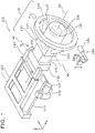
FIG. 1 is a perspective view showing an appearance of a steering system according to an embodiment; -
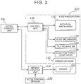
FIG. 2 is a block diagram showing a functional configuration of the steering system according to the embodiment; -
FIG. 3 is a diagram showing an example of a retracting movement of an operation member according to the embodiment; -
FIG. 4 is a diagram showing a dimensional relationship between the operation member according to the embodiment and an opening provided in a dashboard; -
FIG. 5 is a flowchart showing an outline of the retracting movement of the operation member in the steering system according to the embodiment; -
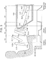
FIG. 6 is a diagram showing a part of a retracting movement of the operation member according to a first modification of the embodiment; -
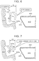
FIG. 7 is a diagram showing a part of a retracting movement of the operation member according to a second modification of the embodiment; -
FIG. 8 is a diagram showing an example of an deploying movement of the operation member according to the embodiment; and -
FIG. 9 is a flowchart showing an example of speed control in the deploying movement of the operation member according to the embodiment. - Hereinafter, the steering system according to an embodiment of the invention and modifications thereof will be specifically described with reference to the drawings. It should be noted that each of the embodiment and the modifications described below illustrates an example. Numerical values, shapes, materials, constituent elements, arrangement positions and connection modes of the constituent elements, steps and the order of the steps, and the like shown in the following embodiment and modifications are merely examples, and do not limit the invention.
- It should be also noted that the drawings are schematic, in which emphasis, omission, and scale adjustment are made as appropriate to illustrate the invention, and may differ from actual shapes, positional relationships, and scales. Further, in the following embodiment, expressions indicating relative directions or postures such as parallel and orthogonal may be used. Note that these expressions include cases in which the directions or postures do not indicate the exact directions or postures. For example, the phrase "two directions are parallel" means that the two directions are completely parallel, and also includes the case in which the two directions are substantially parallel, and for example, a difference of about several percentages is included.
- A steering system according to an embodiment will be described.
FIG. 1 is a perspective view showing an appearance of asteering system 100 according to the embodiment.FIG. 2 is a block diagram showing a functional configuration of thesteering system 100 according to the embodiment. - The
steering system 100 according to the embodiment is a system mounted on a vehicle such as an automobile, a bus, a truck, a construction machine, or an agricultural machine that can switch between manual driving and autonomous driving, for example. - As shown in
FIG. 1 , thesteering system 100 includes anoperation member 110, supportmembers 115 that support theoperation member 110, anairbag housing 120, and arotation mechanism 130. In the embodiment, theoperation member 110 is, for example, an annular member called a steering wheel. More specifically, theoperation member 110 is a member corresponding to a rim of the steering wheel, and thesupport members 115 are members corresponding to spokes of the steering wheel. - The
operation member 110 rotates around a steering axis Aa (a virtual axis extending in a front-rear direction of the vehicle and parallel to an X-axis direction in the embodiment) due to a driver's operation. One or more tires of the vehicle are steered based on a rotation amount of theoperation member 110, and so on. Specifically, thesteering system 100 is a device integrated in a so-called steer-by-wire system, and theoperation member 110 and the tires are not mechanically connected. A motor for steering operation drives the one or more tires based on information output from thesteering system 100 and indicating a steering angle of theoperation member 110, and so on. - For example, in a neutral state in which steered wheels are in a straight running state, the
operation member 110 is supported by thesupport members 115 respectively extending from both sides of therotation mechanism 130 in a width direction of the vehicle (a Y-axis direction in the embodiment), and therotation mechanism 130 rotates around the steering axis Aa as theoperation member 110 rotates around the steering axis Aa. In the embodiment, theairbag housing 120 is fixed to a portion of therotation mechanism 130, which is located on a driver side (on a plus side in the X-axis direction). When theoperation member 110 is viewed from the driver side, theairbag housing 120 is located at the center of theoperation member 110. Anairbag 200 is accommodated in theairbag housing 120 so as to be deployable. Theairbag 200 pushes theairbag housing 120 and breaks through theairbag housing 120 to be deployed when a vehicle collides, for example. Specifically, theairbag 200 operates in accordance with an instruction from an airbag control unit 210 (seeFIG. 2 ) mounted on the vehicle. Theairbag control unit 210 instructs theairbag 200 to deploy, for example, when the vehicle collides with an object. Theairbag control unit 210 determines whether to deploy theairbag 200 based on, for example, vehicle acceleration information received from anacceleration sensor 250. For example, when the vehicle collides with an object, causing a rapid change in acceleration that is equal to or larger than a threshold, theairbag control unit 210 instructs theairbag 200 to deploy, and theairbag 200 activates an inflator so as to deploy. Thus, theairbag 200 is instantly inflated. - The
rotation mechanism 130 is a device that rotates thesupport members 115 with respect to theairbag housing 120 around a rotation axis Ab extending in the width direction of the vehicle. Therotation mechanism 130 includes arotation motor 131 configured to rotate thesupport members 115. In the embodiment, referring to one of thesupport members 115 means referring to the pair ofsupport members 115 connected to therotation mechanism 130. For example, "rotating thesupport member 115" means that the pair ofsupport members 115 connected to therotation mechanism 130 is integrally rotated. Theoperation member 110 does not need to be supported by the pair ofsupport members 115, and theoperation member 110 is supported by at least onesupport member 115. - A driving force of the
rotation mechanism 130 causes thesupport member 115 to rotate around the rotation axis Ab, so that theoperation member 110 supported by thesupport member 115 also rotates about the rotation axis Ab. Theoperation member 110 thus rotates with respect to theairbag housing 120 fixed to therotation mechanism 130. Theoperation member 110 rotates in accordance with a deploying movement and a retracting movement of the operation member 110 (deployment from a storage area and retraction into the storage area). - The
steering system 100 according to the embodiment further includes, as shown inFIG. 1 , aswitch holding unit 140 and areaction force generator 150 disposed in front of the rotation mechanism 130 (on a minus side in the X-axis direction). Theswitch holding unit 140 is a member that holds a switch configured to operate a turn signal, and so on. Theswitch holding unit 140 is connected to a turn signal lever and so on (not shown). - The
reaction force generator 150 is a device that applies a torque against a driver's force to theoperation member 110 when the driver operates theoperation member 110 for steering. Thereaction force generator 150 includes areaction force motor 151 and so on. Thereaction force generator 150 is a device that reproduces, as a reaction force, a force or the like generated on a steering member during driving in the vehicle in the related art in which the tires and the operation member are mechanically connected. That is, in the embodiment, a first end of a shaft body is fixed to therotation mechanism 130, and a second end of the shaft body is connected to thereaction force generator 150. The shaft body is inserted through theswitch holding unit 140 and rotates around the steering axis Aa. Thereaction force generator 150 applies the reaction force to theoperation member 110 via the shaft body. Thereaction force generator 150 controls a rotational position of theoperation member 110 around the steering axis Aa. - The
steering system 100 further includes a mechanism that changes a position and a posture of asteering mechanism 101 including theoperation member 110, thesupport member 115, theairbag housing 120, therotation mechanism 130, theswitch holding unit 140, and thereaction force generator 150 described above. Thus, it is possible to change a distance between theoperation member 110 and the driver and an inclination of theoperation member 110 with respect to the driver. - Specifically, the
steering system 100 includes aslide mechanism 170 as shown inFIG. 1 . Theslide mechanism 170 is an example of a first movement mechanism. Theslide mechanism 170 can move theoperation member 110 between a normal position at which theoperation member 110 is operated by the driver, and a storage area located forward of the normal position. Specifically, theslide mechanism 170 moves theoperation member 110 in the front-rear direction by moving thesteering mechanism 101 including theoperation member 110 in the front-rear direction. - In the embodiment, the
steering mechanism 101 is supported by abase guide 161 via amovable body 162, and themovable body 162 is held by thebase guide 161 so as to be slidable. Thebase guide 161 is fixed to the vehicle via, for example, a bracket (not shown). As shown inFIG. 1 , aslide drive shaft 173 is fixed to thebase guide 161, and a main body including theslide motor 172 is moved along theslide drive shaft 173 by a driving force of theslide motor 172 of theslide mechanism 170. Accordingly, themovable body 162 connected to the main body of theslide mechanism 170 moves in the front-rear direction along thebase guide 161. Thus, thesteering mechanism 101 including theoperation member 110 moves in the front-rear direction. - As shown in
FIG. 1 , thesteering system 100 includes atilt mechanism 180 that changes the inclination of thesteering mechanism 101. InFIG. 1 , to clearly show thetilt mechanism 180, thetilt mechanism 180 is illustrated separately from thesteering mechanism 101 and below thesteering mechanism 101. Thetilt mechanism 180 is an example of a second movement mechanism, and moves theoperation member 110 to change the position of theoperation member 110 in an up-down direction of the vehicle. Specifically, thetilt mechanism 180 can push up thesteering mechanism 101 from a low position to an upper limit position and return the pushedsteering mechanism 101 to a lower limit position with the use of a driving force of atilt motor 181. In the embodiment, thesteering mechanism 101 is supported by themovable body 162 so as to be rotatable around a tilt axis Ac. Thesteering mechanism 101 is driven to move upward and downward by thetilt mechanism 180 such that the inclination angle of thesteering mechanism 101 around the tilt axis Ac is changed. This changes the positions of theoperation member 110, theairbag housing 120, and therotation mechanism 130 in the up-down direction of the vehicle. In thesteering mechanism 101, theoperation member 110, theairbag housing 120, and therotation mechanism 130 are located on the driver side (i.e., located close to the driver). Note that the position of the tilt axis Ac shown inFIG. 1 is an example, and the tilt axis Ac may be located forward (on the minus side in the X-axis direction) of its position shown inFIG. 1 . - The
rotation mechanism 130, thereaction force generator 150, theslide mechanism 170, and thetilt mechanism 180 described above are controlled by a control unit 190 (seeFIG. 2 ) provided in thesteering system 100. Accordingly, theslide mechanism 170 and thetilt mechanism 180 perform operations of changing the position and the posture of thesteering mechanism 101. The operations are performed when the position in the front-rear direction and the height (inclination) of theoperation member 110 are adjusted in accordance with the driver's preference. Therotation mechanism 130 performs an operation of rotating theoperation member 110 around the rotation axis Ab by rotating thesupport member 115. The above-described operations of thereaction force generator 150, theslide mechanism 170, thetilt mechanism 180, and therotation mechanism 130 are performed when theoperation member 110 is deployed from the storage area and retracted into the storage area in the dashboard. Thecontrol unit 190 uses information acquired from each of therotation mechanism 130, theslide mechanism 170, and thetilt mechanism 180 to identify the position, the posture, and the like of theoperation member 110 in the vehicle as necessary. - It should be noted that the deployment and the retraction of the
operation member 110 may be performed in accordance with an instruction from the driver, or may be performed without an instruction from the driver. Specifically, the vehicle including thesteering system 100 is provided with an autonomous (automatic) driving system (not shown) including various sensors, wireless communication functions, and the like, in addition to electric components such as a switch, a button, and a touch panel that receive the instruction from the driver. Accordingly, thesteering system 100 can deploy and retract theoperation member 110 in accordance with the instruction from the driver, and can also deploy and retract theoperation member 110 in cooperation with the autonomous driving system. The vehicle may be provided with sensors that detect various vehicle states such as whether the driver is seated in a driver's seat, opening and closing of a door, and an acceleration of the vehicle. In this case, thesteering system 100 may deploy and retract theoperation member 110 in accordance with the vehicle states detected by the sensors. - For example, when the driver performs a predetermined operation such as pressing a button or inputting voice by speech while the vehicle is in a stop state, the
control unit 190 can retract theoperation member 110 that is in the normal position into the storage area in accordance with the instruction from the driver. Also, for example, when thecontrol unit 190 detects that an autonomous driving level has been changed from a level that requires monitoring by the driver to a level that does not require monitoring by the driver while the vehicle is being driven by the autonomous driving system, thecontrol unit 190 can retract theoperation member 110 that is in the normal position into the storage area without the instruction from the driver. Furthermore, when thecontrol unit 190 detects that the autonomous driving level has been changed from the level that does not require monitoring by the driver to the level that requires monitoring by the driver while the vehicle is being driven by the autonomous driving system, thecontrol unit 190 can deploy theoperation member 110 that is in the storage area without the instruction from the driver. In these cases, when the deploying movement and the retracting movement are not allowed to be performed without the instruction from the driver, automatic deployment and retraction of theoperation member 110 can be restrained. For example, the level that requires monitoring by the driver is a level that is equal to or lower than autonomous driving level 2, and the level that does not require monitoring by the driver is a level that is equal to or higher than autonomous driving level 3. - The autonomous driving level 2 is a level in which the autonomous driving system is allowed to partially perform operations related to driving. The autonomous driving level 3 is a level in which the autonomous driving system is allowed to perform all operations related to driving under limited conditions. In the autonomous driving level 3, monitoring and operation by the driver is necessary in the event of an emergency. In this case, the
operation member 110 needs to be deployed at the normal position (or a position forward of the normal position, at which theoperation member 110 can be operated by the driver) so that the driver can operate theoperation member 110 in the event of an emergency. Autonomous driving level 4 is a level in which the autonomous driving system is allowed to perform all operations related to driving, and the autonomous driving system is also allowed to perform operations in the event of an emergency. In this case, since the driver does not need to operate theoperation member 110, theoperation member 110 is allowed to be retracted into the storage area. - The
control unit 190 that performs the above control is realized by, for example, a computer including a central processing unit (CPU), a storage device such as a memory, and an interface for inputting and outputting information. For example, when the CPU executes a predetermined program stored in the storage device, thecontrol unit 190 can perform movement control for thesteering system 100 in accordance with a control signal transmitted from an upper control unit (i.e., a higher level control unit) 300 or the like and the detection results from the sensor(s). - Here, one feature of the
steering system 100 according to the embodiment is that, when theoperation member 110 is deployed from the storage area or retracted into the storage area, the position or the posture of theoperation member 110 is changed in consideration of the efficiency of the deploying movement and the retracting movement and the safety of the driver. A specific example of the deploying movement and the retracting movement of theoperation member 110 in thesteering system 100 according to the embodiment will be described with reference toFIGS. 3 to 9 . - First, an example of the retracting movement of the
operation member 110 will be described with reference toFIGS. 3 to 5 .FIG. 3 is a diagram showing an example of the retracting movement of theoperation member 110 according to the embodiment.FIG. 4 is a diagram showing a dimensional relationship between theoperation member 110 according to the embodiment and anopening 405 provided in adashboard 400.FIG. 5 is a flowchart showing an outline of the retracting movement of theoperation member 110 in thesteering system 100 according to the embodiment. - In
FIG. 3 , an operation member 110-side part of an area in which the driver is present (i.e., a part of the area, which is located close to the operation member 110) is indicated as a hatcheddriver area 500. Thedashboard 400 is simply shown in section to indicate astorage area 410. InFIG. 3 , illustration of elements other than theoperation member 110, thedashboard 400, and thedriver area 500 is omitted to indicate the positional relationship of theoperation member 110, thedashboard 400, and thedriver area 500. The arrows inFIG. 3 indicate an approximate movement direction or an approximate rotation direction of theoperation member 110. These supplementary items inFIG. 3 also apply toFIGS. 6 to 8 described later. InFIG. 3 , changes in a moving speed of theoperation member 110 are indicated by a line graph associated with approximate positions of theoperation member 110. The movement of theoperation member 110 for deployment and retraction is mainly performed by theslide mechanism 170. Thus, the "moving speed of theoperation member 110" is equal to a speed at which theslide mechanism 170 moves the steering mechanism 101 (seeFIG. 1 ) including theoperation member 110, unless otherwise specified. - In the embodiment, the base guide 161 (see
FIG. 1 ) of thesteering system 100 is fixed to a vehicle body in thedashboard 400. Thesteering system 100 can move theoperation member 110 between the normal position and thestorage area 410 in thedashboard 400. Thedashboard 400 is an example of a vehicle member provided in front of the driver's seat. As shown inFIG. 3 , in thedashboard 400, theopening 405 is provided on a surface facing the driver, and thestorage area 410 for storing the operation member 110 (i.e., thestorage area 410 into which theoperation member 110 is retracted) is provided inward of theopening 405. - In the above configuration, the
steering system 100 retracts theoperation member 110 that is in the normal position into thestorage area 410 while changing the position and the posture of theoperation member 110 as shown inFIG. 3 . As shown inFIG. 4 , a vertical width Wa of theopening 405 is smaller than a vertical width Wb of theoperation member 110. Thus, during the retraction, theoperation member 110 is rotated around the rotation axis Ab (SeeFIG. 1 ) extending in the width direction of the vehicle to be inserted into theopening 405 and accommodated in thestorage area 410. Note that the shape of theopening 405 shown inFIG. 4 is an example, and there is no particular limitation on the shape of theopening 405. Theopening 405 has a shape and a size that allow members such as theoperation member 110 and therotation mechanism 130 to be inserted into theopening 405 and to pass through theopening 405. - The above-described retracting movement of the
operation member 110 in thesteering system 100 can be divided into six sections A1 to A6, for example, as shown inFIG. 3 . Further, as shown inFIG. 3 , the moving speed of theoperation member 110 moved by theslide mechanism 170 also changes. In other words, theoperation member 110 in the normal position enters theopening 405 so as to slide into the opening 405 (A1 to A4) while being moved in the up-down direction and rotated around the rotation axis Ab (seeFIG. 1 ). Thereafter, theoperation member 110 stops at a position at which theoperation member 110 contacts awall 409 in the storage area 410 (A5, A6). - A series of the retracting movement described above include a characteristic movement shown in
FIG. 5 . That is, the retracting movement of theoperation member 110 includes moving theoperation member 110 to the vicinity of thedashboard 400 and moving theoperation member 110 along an outer shape of thedashboard 400. - Specifically, when retracting the
operation member 110 into thestorage area 410, thecontrol unit 190 controls theslide mechanism 170 to move theoperation member 110 as follows. Thecontrol unit 190 moves theoperation member 110 forward at a first speed V1 (S10), and when a distance between theoperation member 110 and thedashboard 400 becomes equal to or less than a predetermined distance L (Yes in S20), thecontrol unit 190 moves theoperation member 110 forward at a second speed V2 (< VI) (S30). In the embodiment, when at least a part of theoperation member 110 reaches a "front position" inFIG. 3 , the moving speed of theoperation member 110 is changed from the first speed V1 to the second speed V2. The front position is, for example, a position at a distance of approximately 5 cm to 10 cm from thedashboard 400. That is, the predetermined distance L is approximately 5 cm to 10 cm. - Thereafter, when the
operation member 110 reaches the vicinity of the dashboard 400 (Yes in S40), thecontrol unit 190 controls theslide mechanism 170 and thetilt mechanism 180 to perform a forward movement (S50) of moving theoperation member 110 along the outer shape of thedashboard 400. The vicinity of thedashboard 400 is a position closer to thedashboard 400 than the above-described front position, and is, for example, a position at a distance of approximately 1 cm to 2 cm from thedashboard 400. - The operations in steps S10 to S30 correspond to the movement in section A2 in
FIG. 3 , and the operations in steps S40 to S50 correspond to the movement in section A3 inFIG. 3 . - As described above, in the embodiment, when the
operation member 110 is moved forward to be retracted, thecontrol unit 190 reduces the moving speed of theoperation member 110 that is triggered by theoperation member 110 reaching a position within the predetermined distance L from thedashboard 400. This reduces the possibility that the driver's finger or the like is caught between theoperation member 110 and thedashboard 400. For example, even when the driver is holding theoperation member 110 at the start of the retraction of theoperation member 110, the driver is given enough time to release his/her hand from theoperation member 110. Also, even when a part of the body of the driver such as the driver's finger or the driver's hand is placed between theoperation member 110 and thedashboard 400 while theoperation member 110 approaches thedashboard 400, theoperation member 110 moves at a low speed (the second speed V2), so there is little possibility that the part of the body of the driver is damaged. In addition, since theoperation member 110 can move at a relatively high speed (the first speed VI) until theoperation member 110 reaches the position within the predetermined distance L from thedashboard 400, the space in front of the driver can be expanded in a relatively short period of time. Moreover, since theoperation member 110 can move at a relatively high speed (the first speed VI) until theoperation member 110 reaches the position within the predetermined distance L from thedashboard 400, an increase in time required for theoperation member 110 to be retracted is restrained. - Note that there is no particular limitation on the method of detecting the distance between the
operation member 110 and thedashboard 400 and the method of detecting the position of theoperation member 110. For example, thecontrol unit 190 may detect the distance between theoperation member 110 and thedashboard 400 using the information (such as an encoder value of the slide motor 172) acquired from theslide mechanism 170. In this case, for example, thecontrol unit 190 may determine that the distance between theoperation member 110 and thedashboard 400 has become equal to or less than the predetermined distance L when a slide amount, which is the distance theslide mechanism 170 has slid, exceeds a predetermined value. The predetermined value may be set in accordance with the normal position before theoperation member 110 is retracted into thestorage area 410. Further, for example, the distance between theoperation member 110 and thedashboard 400 may be detected using a detection result regarding theoperation member 110 from a sensor such as a camera. The detection (calculation) of the distance or the position of theoperation member 110 does not need to be directly performed by thecontrol unit 190. For example, theupper control unit 300 may calculate the distance between theoperation member 110 and thedashboard 400, and thecontrol unit 190 may acquire, from theupper control unit 300, the information indicating the distance therebetween. - The
control unit 190 may also determine the position of theoperation member 110 with respect to the dashboard 400 (S20 and S40 inFIG. 5 ) without directly using the distance between theoperation member 110 and thedashboard 400. For example, thecontrol unit 190 may make the determination by comparing the information acquired from theslide mechanism 170 with information stored in advance. - The
control unit 190 moves theoperation member 110 along the outer shape of thedashboard 400 in the forward movement that is performed after theoperation member 110 reaches the position within the predetermined distance L from thedashboard 400. Specifically, the outer shape of thedashboard 400 in a side view is formed so as to protrude rearward (toward the driver's seat), for example, as shown inFIG. 3 . For example, an upper end side of thedashboard 400 protrudes rearward as compared with a lower end side of thedashboard 400, and thedashboard 400 is formed such that thedashboard 400 is inclined forward, (i.e., the distance from thedriver area 500 increases) in a direction from the upper end side of thedashboard 400 toward the lower end side of thedashboard 400. Theoperation member 110 is moved along the protruding outer shape of thedashboard 400. That is, in the embodiment, in the vicinity of thedashboard 400, theoperation member 110 is moved toward theopening 405 while theoperation member 110 takes such a posture that anupper end portion 110a and alower end portion 110b of theoperation member 110 having a three-dimensional structure are restrained from protruding toward thedriver area 500 as much as possible. This reduces the possibility that theoperation member 110 interferes with the driver while being retracted. - As described above, with the
steering system 100 according to the embodiment, it is possible to expand the space in front of the driver and improve the safety of the driver. - The retracting movement of the
operation member 110 including the above movement will be described in more detail with reference toFIG. 3 . First, in section A1, theoperation member 110 that is in the normal position in front of thedriver area 500 is moved so as to pass aknee area 500a corresponding to the position of the driver's knee. Theknee area 500a is a part of thedriver area 500 and is an area in which the driver's knee is assumed to be located while the driver is seated in the driver's seat. - Specifically, the
control unit 190 controls theslide mechanism 170 and thetilt mechanism 180 to perform initial movement of moving theoperation member 110 forward and moving theoperation member 110 upward simultaneously (i.e., at the same time). - Thus, the
operation member 110 is moved in a path that avoids a knee part of the driver, which is likely to interfere with theoperation member 110 when theoperation member 110 is moved forward. The safety of the driver is therefore improved. Further, theslide mechanism 170 moves theoperation member 110 forward and thetilt mechanism 180 moves theoperation member 110 upward simultaneously (i.e., at the same time). Thus, theoperation member 110 is moved forward in the shortest distance, for example, while avoiding theknee area 500a. This is advantageous for increasing the efficiency of the retracting movement of theoperation member 110. - In the embodiment, the moving speed of the
operation member 110 in the initial movement is, for example, a speed between the first speed V1 and the second speed V2 described above. Specifically, in the initial movement, thecontrol unit 190 controls theslide mechanism 170 to move theoperation member 110 forward at a third speed V3 that is higher than the second speed V2 and lower than the first speed V1. When the initial movement ends, thecontrol unit 190 changes the moving speed of theoperation member 110 to the first speed V1. - With the above configuration, in the initial movement that is performed in front of the driver and at least involves the upward movement of the
operation member 110, theoperation member 110 is moved forward at the third speed V3 that is an intermediate speed. Thus, theoperation member 110 can be moved forward efficiently while ensuring the safety of the driver. Moreover, the moving speed of theoperation member 110 is changed to the first speed V1 that is higher than the third speed V3 when theoperation member 110 reaches a position at which it is assumed that theoperation member 110 has mostly passed theknee area 500a (i.e., when theoperation member 110 reaches a boundary position between the section A1 and the section A2), and the moving speed of theoperation member 110 is the first speed V1 thereafter. This restrains the increase in the time required for theoperation member 110 to be retracted. When thecontrol unit 190 changes the moving speed of theoperation member 110 from the third speed V3 to the first speed VI, thecontrol unit 190 may control the movement of theoperation member 110 so that the moving speed gradually increases. In this way, for example, the driver can easily recognize the increase in the moving speed of theoperation member 110, thereby further reducing the possibility that theoperation member 110 interferes with the driver while being retracted. - In the
steering system 100 according to the embodiment, in the initial movement, thecontrol unit 190 further controls therotation mechanism 130 to change the posture of theoperation member 110 so as to ensure the safety of the driver more reliably. Specifically, in the initial movement, thecontrol unit 190 further controls therotation mechanism 130 to rotate theoperation member 110 so that thelower end portion 110b of theoperation member 110 is moved upward. - Thus, in the initial movement, the
operation member 110 is rotated so that thelower end portion 110b of theoperation member 110 is lifted. This reduces the possibility that theoperation member 110 interferes with the knee part of the driver when theoperation member 110 is retracted. More specifically, it is preferable that theoperation member 110 be rotated in a direction in which theupper end portion 110a falls forward (in a clockwise direction inFIG. 3 ). Thus, thelower end portion 110b of theoperation member 110 is lifted while moving rearward (in a direction away from the knee part of the driver) with respect to therotation mechanism 130. This further reduces the possibility that theoperation member 110 interferes with the knee part of the driver when being retracted. Even when a moving amount of theoperation member 110 moved by thetilt mechanism 180 is relatively small, as long as therotation mechanism 130 rotates theoperation member 110, thelower end portion 110b of theoperation member 110 can be lifted to a position high enough to avoid theknee area 500a. Thus, the forward movement of theoperation member 110 while avoiding theknee area 500a can be performed more quickly and safely. - After the initial movement, in the section A2, as described above, the
control unit 190 moves theoperation member 110 at the first speed V1. In the section A2, theoperation member 110 that is rotated so that theupper end portion 110a is tilted forward in the initial movement (the section A1 inFIG. 3 ) is moved to the front position at the first speed V1 while being rotated in a reverse direction (a direction in which thelower end portion 110b faces forward), for example. That is, thecontrol unit 190 controls therotation mechanism 130 and theslide mechanism 170 to move theoperation member 110 forward, while raising theoperation member 110 that has been tilted so as to fall forward. - Thereafter, when a part of the operation member 110 (for example, the
upper end portion 110a) reaches the front position, that is, when the distance between theoperation member 110 and thedashboard 400 becomes equal to or less than the predetermined distance L, the moving speed of theoperation member 110 is reduced as described above. Specifically, thecontrol unit 190 controls theslide mechanism 170 to change the moving speed of theoperation member 110 from the first speed V1 to the second speed V2. - After the
operation member 110 has reached the front position, in the section A3, theoperation member 110 is brought closer to thedashboard 400 at a low speed (the second speed V2). Then, as described above, after theoperation member 110 has reached the vicinity of thedashboard 400, theoperation member 110 moves toward theopening 405 in the forward movement. That is, theoperation member 110 is moved along the outer shape of thedashboard 400 under the control of thecontrol unit 190. - Specifically, the
control unit 190 controls therotation mechanism 130 to tilt theoperation member 110 in a direction in which thelower end portion 110b faces forward (in a counterclockwise direction inFIG. 3 ) as shown inFIG. 3 . At this time, theoperation member 110 is moved closer to theopening 405 by theslide mechanism 170 and thetilt mechanism 180. That is, thecontrol unit 190 further controls therotation mechanism 130 to move theupper end portion 110a of theoperation member 110 along the outer shape of thedashboard 400 in the forward movement. - Since the
operation member 110 is rotated in the counterclockwise direction inFIG. 3 in the forward movement, theupper end portion 110a of theoperation member 110 may protrude toward thedriver area 500. Thus, thecontrol unit 190 according to the embodiment controls theslide mechanism 170, thetilt mechanism 180, and therotation mechanism 130 to move theoperation member 110 so that theupper end portion 110a of theoperation member 110 moves along the outer shape of thedashboard 400. This reduces the amount of protrusion of theoperation member 110 toward thedriver area 500 in the forward movement, and thereby reduces the possibility that theoperation member 110 interferes with the driver. - As shown in
FIG. 4 , the vertical width Wb of theoperation member 110 is larger than the vertical width Wa of theopening 405 when theoperation member 110 is disposed along theopening 405 and viewed from an opening direction in which theopening 405 is opened. When inserting theoperation member 110 into theopening 405, thecontrol unit 190 controls theslide mechanism 170, thetilt mechanism 180, and therotation mechanism 130 to insert theoperation member 110 into the opening 405 from thelower end portion 110b, theoperation member 110 being rotated such that thelower end portion 110b of theoperation member 110 faces forward. - That is, when the
operation member 110 is moved so that theupper end portion 110a of theoperation member 110 is moved along the outer shape of thedashboard 400, theoperation member 110 is rotated so that thelower end portion 110b faces forward in the section A4. As an extension of the flow of the series of the movement, theoperation member 110 is inserted into the opening 405 from thelower end portion 110b. That is, theoperation member 110 enters thestorage area 410 through theopening 405 with an efficient movement. Thus, the retracting movement of theoperation member 110 can be performed efficiently, and theopening 405 can be made relatively small. By reducing the size of theopening 405, for example, the strength or the rigidity of thedashboard 400 can be easily secured. When theopening 405 is closed by an opening/closing mechanism such as a door or a shutter, the configuration of the opening/closing mechanism can be simplified by reducing the size of theopening 405. - After the
operation member 110 has been inserted into theopening 405 in the section A4, thecontrol unit 190 increases the moving speed of theoperation member 110 in the section A5. Specifically, thecontrol unit 190 increases the moving speed at which theoperation member 110 is moved forward by theslide mechanism 170 after at least a part of theoperation member 110 has reached the inside of thestorage area 410 and the downward movement of theoperation member 110 caused by thetilt mechanism 180 has been completed. - That is, when the
operation member 110 has reached thestorage area 410, the issue of interference between theoperation member 110 and the driver does not occur, and thus, thecontrol unit 190 moves theoperation member 110 at a high speed with priority being given to efficiency. For example, as shown inFIG. 3 , thecontrol unit 190 moves theoperation member 110 at a fourth speed V4 that is the highest speed in the retracting movement of theoperation member 110. - When the
operation member 110 has reached a predetermined position, that is, a first predetermined position in the storage area 410 (an end of the section A5 inFIG. 3 ), thecontrol unit 190 further controls thetilt mechanism 180 to move theoperation member 110 upward in thestorage area 410. - Here, since the
operation member 110 is retracted obliquely downward in thestorage area 410, a relatively low position in front of the driver can be set as the retracted position (final position in the retracting movement). However, when a collision of the vehicle occurs in a state where theoperation member 110 is in the retracted position, a lower leg of the driver may collide with theoperation member 110 that is fixed in thesteering system 100. In view of this, in thesteering system 100 according to the embodiment, an operation of lifting theoperation member 110 upward is performed as the last movement in the retracting movement of theoperation member 110. This reduces the possibility of collision between theoperation member 110 and the lower leg of the driver in the state in which theoperation member 110 is retracted. - Further, in the embodiment, at the completion of the retraction of the
operation member 110, theoperation member 110 is stopped while contacting a member of which the position is fixed in the vehicle. That is, thecontrol unit 190 completes the retraction of theoperation member 110 with a portion of theoperation member 110 contacting a surface defining thestorage area 410 or a member fixed in thestorage area 410. For example, as shown inFIG. 3 , theoperation member 110 is stopped with thelower end portion 110b of theoperation member 110 contacting thewall 409 in thestorage area 410. More specifically, theoperation member 110 is stopped with thelower end portion 110b being pressed against thewall 409. - With the above configuration, for example, when the vehicle is driven by the autonomous driving system with the
operation member 110 being in the retracted position, vibration or movement of theoperation member 110 is restrained. This restrains occurrence of abnormal noise or damage to theoperation member 110 due to contact of theoperation member 110 with a nearby member, for example. The shape or the position of the member that theoperation member 110 contacts is not limited. For example, theoperation member 110 may stop while contacting a bottom surface of thedashboard 400. By providing a flexible member such as rubber at the portion that theoperation member 110 contacts, theoperation member 110 can be firmly pressed against the portion without causing damage to theoperation member 110. - Although the retracting movement of the
operation member 110 in thesteering system 100 according to the embodiment has been described above, the retracting movement described above is an example, and a part of the retracting movement may be replaced with a different movement. Modifications of the retracting movement of theoperation member 110 will be described with reference toFIGS. 6 and 7 . -
FIG. 6 is a diagram showing a part of the retracting movement of theoperation member 110 according to a first modification of the embodiment. Specifically,FIG. 6 shows an outline of an initial movement in the first modification. As shown inFIG. 6 , at the start of the retraction of theoperation member 110 into thestorage area 410, thecontrol unit 190 according to the first modification controls theslide mechanism 170 and thetilt mechanism 180 to start the forward movement of theoperation member 110 after the upward movement of theoperation member 110. As described above, by moving theoperation member 110 such that theoperation member 110 escapes upward first, and then moving theoperation member 110 forward, theoperation member 110 can be moved forward while avoiding theknee area 500a. -
FIG. 7 is a diagram showing a part of the retracting movement of theoperation member 110 according to a second modification of the embodiment. Specifically,FIG. 7 shows an outline of an initial movement in the second modification. As shown inFIG. 7 , at the start of the retraction of theoperation member 110 into thestorage area 410, thecontrol unit 190 according to the second modification controls theslide mechanism 170 and therotation mechanism 130 to perform the initial movement of moving theoperation member 110 forward and rotating theoperation member 110 simultaneously (i.e., at the same time). - That is, when the
operation member 110 is retracted, theknee area 500a can be avoided by rotating theoperation member 110 around the rotation axis Ab (seeFIG. 1 ) without moving theoperation member 110 upward. In this case, the rotation direction of theoperation member 110 may be the clockwise direction inFIG. 7 or the counterclockwise direction inFIG. 7 . As shown inFIG. 7 , when the rotation direction of theoperation member 110 is the clockwise direction, for example, theoperation member 110 can be moved forward while theupper end portion 110a of theoperation member 110 is tilted forward (that is, thelower end portion 110b is moved so as to escape rearward and upward). Thus, the retracting movement of theoperation member 110 can be performed efficiently. - Next, an example of the deploying movement of the
operation member 110 will be described with reference toFIGS. 8 and 9. FIG. 8 is a diagram showing an example of the deploying movement of theoperation member 110 according to the embodiment.FIG. 9 is a flowchart showing an example of speed control in the deploying movement of theoperation member 110 according to the embodiment. - As shown in
FIG. 8 , thesteering system 100 according to the embodiment can deploy theoperation member 110 that is retracted in thestorage area 410 to the normal position. When a trajectory of theoperation member 110 in the deployment (deploying movement) of theoperation member 110 is followed in reverse, the trajectory substantially coincides with a trajectory of theoperation member 110 in the retracting movement of theoperation member 110 that has been described with reference to figures includingFIG. 3 . That is, there is a mutually inverse relationship between a transition of the position and the posture of theoperation member 110 in the deploying movement of theoperation member 110 and a transition of the position and the posture of theoperation member 110 in the retracting movement of theoperation member 110 that has been described with reference to figures includingFIG. 3 . - The deploying movement of the
operation member 110 is performed as follows under the control of thecontrol unit 190. Theoperation member 110 that is stopped while contacting thewall 409 in thestorage area 410 is moved rearward (toward the opening 405) by theslide mechanism 170 and thetilt mechanism 180. At this time, theoperation member 110 moves at a maximum speed while theentire operation member 110 is located within thestorage area 410. Thereafter, theoperation member 110 moves out of theopening 405 from theupper end portion 110a at a reduced moving speed. Theoperation member 110 that has moved out of theopening 405 is moved along the outer shape of thedashboard 400 by theslide mechanism 170, thetilt mechanism 180, and therotation mechanism 130. Thereafter, theoperation member 110 is moved rearward at an increased speed by theslide mechanism 170, and is further moved upward by thetilt mechanism 180 so as to avoid theknee area 500a of thedriver area 500. At this time, theoperation member 110 that has been tilted so that theupper end portion 110a faces forward is rotated by therotation mechanism 130 in a direction in which theupper end portion 110a moves rearward. When theoperation member 110 has passed theknee area 500a, theslide mechanism 170 reduces the moving speed of theoperation member 110, and thetilt mechanism 180 moves theoperation member 110 downward. Thereafter, theoperation member 110 stops at the normal position. The normal position in this case may be a position that has been set immediately before theoperation member 110 is retracted (a position adjusted in accordance with the driver's preference), or may be a position matching a body shape or the like of the driver who is seated in the driver's seat when theoperation member 110 is deployed. Information such as the body shape of the driver may be detected as necessary by a sensor such as a camera, or may be derived from attribute information for each driver stored in a storage device in advance. - Thus, as in the case of the retracting movement, when the
operation member 110 is deployed, the moving speed of theoperation member 110 is changed to achieve both effects of securing the safety of the driver and moving theoperation member 110 efficiently. Basically, as in the case of the retracting movement of theoperation member 110, when the possibility of interference between theoperation member 110 and the driver is low, the moving speed of theoperation member 110 is increased, and when the possibility of interference between theoperation member 110 and the driver is high, the moving speed of theoperation member 110 is reduced. - For example, in the embodiment, in the deploying movement of the
operation member 110 to the normal position, when theoperation member 110 that has started to move toward the normal position reaches a predetermined position, that is, a second predetermined position, thecontrol unit 190 of thesteering system 100 controls theslide mechanism 170 to reduce the moving speed and controls thetilt mechanism 180 to move theoperation member 110 upward. In the embodiment, the predetermined position is a position in the vicinity of theknee area 500a, for example, any position in the section A2 inFIG. 3 . - That is, in the deploying movement of the
operation member 110, when theoperation member 110 moves rearward through theopening 405 and approaches theknee area 500a, thetilt mechanism 180 moves theoperation member 110 upward. At this time, theoperation member 110 reaches a position close to the driver. Thus, thecontrol unit 190 reduces the moving speed of theoperation member 110 moved by theslide mechanism 170. The moving speed at this time is, for example, approximately the second speed V2 (seeFIG. 1 ). Then, after theoperation member 110 has passed theknee area 500a, thetilt mechanism 180 moves theoperation member 110 downward such that theoperation member 110 is returned to the normal position. The moving speed at this time is also approximately the second speed V2. Thus, even if theoperation member 110 contacts the driver, there is little possibility of causing substantial harm to the driver. Therefore, with thesteering system 100 according to the embodiment, the safety of the driver is improved also in the deploying movement of theoperation member 110. - Further, as described above, the deployment and the retraction of the
operation member 110 may be performed in accordance with the instruction from the driver, or may be performed without the instruction from the driver. For example, a case is assumed in which thecontrol unit 190 detects in advance that the autonomous driving level will be changed from the level that does not require monitoring by the driver to the level that requires monitoring by the driver, while the vehicle is being driven by the autonomous driving system. In this case, thecontrol unit 190 may deploy the retractedoperation member 110 to the normal position before the autonomous driving level is changed to the level that requires monitoring by the driver regardless of the instruction from the driver. In this case, the deploying movement of theoperation member 110 is not started by the instruction from the driver, and thus the driver may not be prepared for the deployment of theoperation member 110. In view of this, thesteering system 100 according to the embodiment performs control to change the moving speed of theoperation member 110 depending on whether the deploying movement of theoperation member 110 is performed in accordance with the instruction from the driver. In other words, in the case where theoperation member 110 that is retracted in thestorage area 410 is deployed to the normal position, thecontrol unit 190 moves theoperation member 110 at a higher moving speed when theoperation member 110 is deployed in accordance with the instruction from the driver than when theoperation member 110 is deployed without the instruction from the driver. - Specifically, as shown in
FIG. 9 , thecontrol unit 190 receives an instruction to deploy the operation member 110 (deployment instruction) (SI00). When the deployment instruction is the instruction from the driver (Yes in S110), thecontrol unit 190 controls theslide mechanism 170 to move theoperation member 110 at a moving speed Va (S120). In other words, when the driver gives the deployment instruction to thecontrol unit 190 by performing a predetermined operation such as an operation of pressing a button, thecontrol unit 190 moves theoperation member 110 at the moving speed Va. For example, theoperation member 110 moves at the moving speed Va in a section from when theoperation member 110 moves along the outer shape of thedashboard 400 and appears in front of the driver to when theoperation member 110 reaches theknee area 500a. - When the received deployment instruction is not the instruction from the driver (No in S110), the
control unit 190 controls theslide mechanism 170 to move theoperation member 110 at a moving speed Vb (< Va) (S121). Cases in which the deployment instruction is not the instruction from the driver includes, in addition to the case in which the deployment instruction is an instruction from the autonomous driving system as described above, a case in which thecontrol unit 190 detects via a sensor such as a camera that the driver has been seated on the driver's seat that had been vacant, for example. Like the moving speed Va, the moving speed Vb is the moving speed of theoperation member 110 in a section from when theoperation member 110 appears in front of the driver to when theoperation member 110 reaches theknee area 500a. - As described above, in the deploying movement of the
operation member 110, thecontrol unit 190 slowly moves theoperation member 110 closer to the driver when the deployment instruction is not the instruction from the driver. As a result, even if the driver does not recognize the deployment of theoperation member 110, the driver is given a relatively long period of time to recognize the deployment of theoperation member 110. This reduces the possibility of interference between the movingoperation member 110 and the driver. - The steering system according to the invention has been described based on the embodiment and the modifications thereof. However, the invention is not limited to the above embodiment and the above modifications. Various changes and modifications may be made to the above embodiment or the above modifications, or constituent elements described above may be combined without departing from the scope of the invention.
- For example, the
operation member 110 need not be annular in shape as shown inFIG. 1 . For example, theoperation member 110 may have a C-shape or a U-shape in which one of the upper end portion and the lower end portion of the annular shape is omitted, or an H-shape in which both the upper end portion and the lower end portion of the annular shape are omitted. Even in this case, by rotating theoperation member 110 around the rotation axis Ab, theoperation member 110 can be inserted into theopening 405 having a smaller vertical width than that of theoperation member 110. - In the embodiment, the
slide mechanism 170 moves theoperation member 110 in the front-rear direction by sliding themovable body 162 with respect to thebase guide 161. Alternatively, themovable body 162 itself may have a telescopic structure that moves theoperation member 110 forward and rearward. For example, themovable body 162 may include a first movable body that slides with respect to thebase guide 161 and a second movable body that slides with respect to the first movable body and that is connected to thesteering mechanism 101. In this case, since themovable body 162 can slide with respect to thebase guide 161 and can expand and contract, theoperation member 110 can be moved in a wider range in the front-rear direction. In this case, theslide mechanism 170 may include a first drive portion that moves the first movable body with respect to thebase guide 161 and a second drive portion that moves the second movable body with respect to the first movable body. Thus, for example, theoperation member 110 can be moved at a higher speed or with a larger driving force. - Further, the driver may be notified of the start of the retraction or the deployment of the
operation member 110 before the start of the retraction or the deployment of theoperation member 110 by one of or a combination of a voice, information displayed on a display, and blinking of a light emitting element. Thus, an alert regarding the movement of theoperation member 110 is given to the driver, and accordingly, interference between the movingoperation member 110 and the driver is restrained. - After receiving the notification of the retraction or the deployment of the
operation member 110, the driver may notify thecontrol unit 190 whether to allow or disallow the retraction or the deployment of theoperation member 110 by a predetermined operation such as an operation of pressing a button. For example, even in the case where the retraction of theoperation member 110 is allowed in a state in which the vehicle can be driven by the autonomous driving system, the retraction of theoperation member 110 may be disallowed based on the intention of the driver. In this case, the driver operates theoperation member 110 or the like to drive the vehicle. - The structure and the shape of the
dashboard 400 need not necessarily be the structure and the shape shown inFIG. 3 . For example, theopening 405 may be provided on a lower surface of thedashboard 400. That is, theoperation member 110 may be stored in thestorage area 410 inside thedashboard 400 through the opened portion of the lower surface of thedashboard 400. In this case, for example, a general dashboard having a structure with an opened lower surface can be provided on the vehicle together with thesteering system 100. That is, even when the dashboard is not provided with an opening for storing (retracting) theoperation member 110, it is possible to mount thesteering system 100 on a vehicle including the dashboard. - Further, the
steering system 100 may not include theairbag 200. That is, regardless of whether thesteering system 100 is provided with theairbag 200 and theairbag housing 120, theoperation member 110 can be deployed from thestorage area 410 and retracted into thestorage area 410 safely and efficiently. - In the embodiment, the rotation axis Ab around which the
operation member 110 is rotated by therotation mechanism 130 is located forward of theoperation member 110 inFIG. 1 , but the position of the rotation axis Ab of theoperation member 110 is not limited to this. For example, thesupport member 115 connecting therotation mechanism 130 and theoperation member 110 may extend from therotation mechanism 130 so as to be parallel to the width direction of the vehicle (the Y-axis direction inFIG. 1 ). In this case, theoperation member 110 rotates around the rotation axis Ab that is located in the same position as the position of theoperation member 110 in the front-rear direction. Thus, when the rotation axis Ab is located in the same position as, or in the vicinity of the position of theoperation member 110 in the front-rear direction, theoperation member 110 can be rotated around the rotation axis Ab within a relatively small spatial area. - Further, the
steering system 100 may not include therotation mechanism 130. That is, the retraction of theoperation member 110 into thestorage area 410 and the deployment of theoperation member 110 from thestorage area 410 may be performed by a combination of the movement in the front-rear direction caused by theslide mechanism 170 and the movement in the up-down direction by thetilt mechanism 180. The fact that thesteering system 100 includes therotation mechanism 130 is advantageous in view of improving the degree of freedom of the posture of theoperation member 110. That is, since thesteering system 100 includes therotation mechanism 130, for example, theoperation member 110 is easily moved along the outer shape of thedashboard 400, and theoperation member 110 is easily inserted into the relativelysmall opening 405. - Further, the sections A1 to A6 shown in
FIG. 3 are sections that are set for convenience in describing an example of the retracting movement of theoperation member 110, and the moving speed or the posture or the like of theoperation member 110 need not be changed clearly at start points or end points of these sections. The number and the width of the sections shown inFIG. 3 are also examples, and the number and the width of the sections are not limited to specific values. - The invention is useful as a steering system capable of expanding the space in front of the driver and improving the safety of the driver. The invention is applicable to, for example, a vehicle, such as an automobile, a bus, a truck, agricultural equipment, or construction equipment, which has wheels, a crawler, or the like and which can be manually driven and autonomously driven.
Claims (9)
- A steering system configured to steer a vehicle, the steering system comprising:a steering wheel (110) configured to perform an operation;a first movement mechanism configured to move the steering wheel (110) between a normal position at which the steering wheel (110) is operated by a driver, and a storage area (410) located forward of the normal position;a second movement mechanism configured to move the steering wheel (110) so as to change a position of the steering wheel (110) in an up-down direction of the vehicle; anda control unit (190) configured to control the first movement mechanism and the second movement mechanism, whereinthe storage area (410) is located inward of an opening (405) of a dashboard (400) provided in front of a driver's seat in the vehicle; characterized in that:the control unit (190) is configured to control, in a case where the steering wheel (110) is retracted into the storage area (410), the first movement mechanism and the second movement mechanism to perform a forward movement of moving the steering wheel (110) that has reached a vicinity of the dashboard (400), along an outer shape of the dashboard (400), andthe first movement mechanism and the second movement mechanism are controlled to move simultaneously.
- The steering system according to claim 1, characterized by further comprising
a rotation mechanism configured to rotate the steering wheel (110) around a rotation axis extending in a width direction of the vehicle, wherein the control unit (190) is configured to further control the rotation mechanism to move the upper end portion of the steering wheel (110) along the outer shape of the dashboard (400) in the forward movement. - The steering system according to claim 2, characterized in that:a vertical width of the steering wheel (110) is larger than a vertical width of the opening when the steering wheel (110) is disposed along the opening and viewed from an opening direction in which the opening is opened; andthe control unit (190) is configured to control the first movement mechanism, the second movement mechanism, and the rotation mechanism to insert the steering wheel (110) into the opening from the lower end portion of the steering wheel (110), the steering wheel (110) being rotated such that the lower end portion of the steering wheel (110) faces forward, in a case where the steering wheel (110) is inserted into the opening.
- The steering system according to any one of claims 1 to 3, characterized in that the control unit (190) is configured to increase a moving speed at which the steering wheel (110) is moved forward by the first movement mechanism after at least a part of the steering wheel (110) has reached an inside of the storage area (410) and a downward movement of the steering wheel (110) caused by the second movement mechanism has been completed, in the case where the steering wheel (110) is retracted into the storage area (410).
- The steering system according to any one of claims 1 to 4, characterized in that the control unit (190) is configured to control the second movement mechanism to move the steering wheel (110) upward in the storage area (410) when the steering wheel (110) reaches a predetermined position in the storage area (410) in the case where the steering wheel (110) is retracted into the storage area (410).
- The steering system according to any one of claims 1 to 5, characterized in that the control unit (190) is configured to complete retraction of the steering wheel (110) with a portion of the steering wheel (110) contacting a surface defining the storage area (410) or a member fixed in the storage area (410), in the case where the steering wheel (110) is retracted into the storage area (410).
- The steering system according to any one of claims 1 to 6, characterized in that the control unit (190) is configured to control the first movement mechanism to reduce a moving speed of the steering wheel (110) and to control the second movement mechanism to move the steering wheel (110) upward when the steering wheel (110) that has started to move toward the normal position reaches a predetermined position, in a case where the steering wheel (110) that is retracted in the storage area (410) is deployed to the normal position.
- The steering system according to any one of claims 1 to 7, characterized in that the control unit (190) is configured to move the steering wheel (110) at a higher moving speed when the steering wheel (110) that is retracted in the storage area (410) is deployed to the normal position in accordance with an instruction from the driver than when the steering wheel (110) that is retracted in the storage area (410) is deployed to the normal position without the instruction from the driver.
- The steering system according to any one of claims 1 to 8, characterized in that the steering wheel (110) is moved toward the opening (405) while the steering wheel (110) takes such a posture that an upper end portion (110a) and a lower end portion (110b) of the steering wheel (110) having a three-dimensional structure are restrained from protruding toward a driver area (500) as much as possible.
Applications Claiming Priority (1)
| Application Number | Priority Date | Filing Date | Title |
|---|---|---|---|
| JP2019138975A JP7310411B2 (en) | 2019-07-29 | 2019-07-29 | steering device |
Publications (2)
| Publication Number | Publication Date |
|---|---|
| EP3771619A1 EP3771619A1 (en) | 2021-02-03 |
| EP3771619B1 true EP3771619B1 (en) | 2022-05-04 |
Family
ID=71783903
Family Applications (1)
| Application Number | Title | Priority Date | Filing Date |
|---|---|---|---|
| EP20187405.4A Active EP3771619B1 (en) | 2019-07-29 | 2020-07-23 | Steering system |
Country Status (4)
| Country | Link |
|---|---|
| US (1) | US11198464B2 (en) |
| EP (1) | EP3771619B1 (en) |
| JP (1) | JP7310411B2 (en) |
| CN (1) | CN112298328A (en) |
Families Citing this family (12)
| Publication number | Priority date | Publication date | Assignee | Title |
|---|---|---|---|---|
| KR102111357B1 (en) * | 2018-09-21 | 2020-05-15 | 주식회사 만도 | Steering column for vehicle |
| US11472465B2 (en) * | 2019-04-25 | 2022-10-18 | Jtekt Corporation | Steering device |
| US11292502B2 (en) * | 2020-02-10 | 2022-04-05 | Caterpillar Inc. | Steering assembly |
| CN113548107A (en) * | 2020-04-09 | 2021-10-26 | 株式会社万都 | Folding steering wheel assembly and steering device comprising folding steering wheel assembly |
| CN113562061A (en) * | 2020-04-29 | 2021-10-29 | 株式会社万都 | Steering column with folding steering wheel structure |
| WO2023031889A2 (en) * | 2021-09-06 | 2023-03-09 | Zf Automotive Technologies (shanghai) Co., Ltd. | Vehicle interior system, control method for vehicle interior system, and related device |
| DE102021210120A1 (en) | 2021-09-14 | 2023-03-16 | Robert Bosch Gesellschaft mit beschränkter Haftung | Adjustable steering column for a motor vehicle steer-by-wire system |
| US11667321B2 (en) * | 2021-09-30 | 2023-06-06 | Ford Global Technologies, Llc | Interior system of a vehicle |
| DE102022108042A1 (en) | 2022-04-04 | 2023-10-05 | Bayerische Motoren Werke Aktiengesellschaft | Scenting system for scenting the interior of a vehicle |
| EP4032783B1 (en) * | 2022-05-11 | 2024-05-01 | thyssenkrupp Presta AG | Steering column for a motor vehicle |
| US11745786B1 (en) * | 2022-07-21 | 2023-09-05 | GM Global Technology Operations LLC | Steering control system having a telescoping steering wheel rim |
| CN116142278A (en) * | 2022-10-27 | 2023-05-23 | 浙江极氪智能科技有限公司 | Tubular column subassembly and car |
Citations (1)
| Publication number | Priority date | Publication date | Assignee | Title |
|---|---|---|---|---|
| FR2806042A1 (en) * | 2000-03-13 | 2001-09-14 | Renault | Retractable steering wheel for motor vehicle has retractable table under dashboard supporting pivoted mounting for steering wheel |
Family Cites Families (15)
| Publication number | Priority date | Publication date | Assignee | Title |
|---|---|---|---|---|
| US5419215A (en) * | 1989-09-05 | 1995-05-30 | Ultra-Precision Manufacturing Ltd. | Automatic steering wheel pivoting mechanism |
| IT1286722B1 (en) * | 1996-04-16 | 1998-07-17 | Fiat Auto Spa | RECLINABLE STEERING WHEEL, PARTICULARLY FOR VEHICLES. |
| FR2861657B1 (en) | 2003-11-04 | 2007-01-19 | Peugeot Citroen Automobiles Sa | DRIVING STATION OF A MOTOR VEHICLE |
| US8862331B2 (en) * | 2011-10-26 | 2014-10-14 | Jtekt Corporation | Controller for steering apparatus |
| US20140260761A1 (en) * | 2013-03-15 | 2014-09-18 | Ford Global Technologies, Llc | Method and system for stowing steering column in a vehicle |
| EP3042825B1 (en) * | 2015-01-12 | 2022-03-09 | Volvo Car Corporation | A steering wheel assembly for retracting a steering wheel in a vehicle |
| US10343706B2 (en) | 2015-06-11 | 2019-07-09 | Steering Solutions Ip Holding Corporation | Retractable steering column system, vehicle having the same, and method |
| CN107416008A (en) * | 2016-04-13 | 2017-12-01 | 法拉第未来公司 | The system and method for making steering wheel for vehicle retract and stretch out automatically |
| DE102016225297A1 (en) * | 2016-12-16 | 2018-06-21 | Thyssenkrupp Ag | Steering wheel for a motor vehicle steering and steering column for a motor vehicle |
| FR3064239B1 (en) | 2017-03-21 | 2021-05-14 | Faurecia Interieur Ind | VEHICLE TRIM PANEL WITH STEERING ASSEMBLY |
| JP6657160B2 (en) | 2017-10-25 | 2020-03-04 | 本田技研工業株式会社 | Vehicle operation system, vehicle operation method, and program |
| JP7091789B2 (en) * | 2018-04-04 | 2022-06-28 | 株式会社ジェイテクト | Steering device |
| JP7192362B2 (en) * | 2018-09-28 | 2022-12-20 | 株式会社ジェイテクト | steering device |
| US11472465B2 (en) * | 2019-04-25 | 2022-10-18 | Jtekt Corporation | Steering device |
| JP7400244B2 (en) * | 2019-07-29 | 2023-12-19 | 株式会社ジェイテクト | steering device |
-
2019
- 2019-07-29 JP JP2019138975A patent/JP7310411B2/en active Active
-
2020
- 2020-07-15 US US16/929,385 patent/US11198464B2/en active Active
- 2020-07-15 CN CN202010679925.9A patent/CN112298328A/en active Pending
- 2020-07-23 EP EP20187405.4A patent/EP3771619B1/en active Active
Patent Citations (1)
| Publication number | Priority date | Publication date | Assignee | Title |
|---|---|---|---|---|
| FR2806042A1 (en) * | 2000-03-13 | 2001-09-14 | Renault | Retractable steering wheel for motor vehicle has retractable table under dashboard supporting pivoted mounting for steering wheel |
Also Published As
| Publication number | Publication date |
|---|---|
| US20210031823A1 (en) | 2021-02-04 |
| US11198464B2 (en) | 2021-12-14 |
| EP3771619A1 (en) | 2021-02-03 |
| JP2021020581A (en) | 2021-02-18 |
| CN112298328A (en) | 2021-02-02 |
| JP7310411B2 (en) | 2023-07-19 |
Similar Documents
| Publication | Publication Date | Title |
|---|---|---|
| EP3771619B1 (en) | Steering system | |
| EP3771618B1 (en) | Steering system | |
| US11472465B2 (en) | Steering device | |
| US10800441B2 (en) | Retractable steering wheel | |
| US10343706B2 (en) | Retractable steering column system, vehicle having the same, and method | |
| CN106904213B (en) | Movable steering wheel for autonomous vehicle | |
| US20220080917A1 (en) | Roof airbag system and vehicle | |
| EP3851360B1 (en) | Steering system | |
| JP2021169257A (en) | Steering device | |
| JP7268524B2 (en) | steering device | |
| JP6515861B2 (en) | Occupant protection device | |
| JP5110352B2 (en) | Electric steering column device | |
| JP7119535B2 (en) | steering device | |
| JP2009083556A (en) | Steering device equipped with knee airbag attached to column | |
| JP4083653B2 (en) | Active knee bolster | |
| JP4095928B2 (en) | Vehicle occupant protection device | |
| JP4538902B2 (en) | Control device for vehicle steering mechanism | |
| JP2020179841A (en) | Steering device | |
| JP2004352097A (en) | Occupant protection device for vehicle | |
| KR20050008106A (en) | Automotive steering column device with saft zone in case of collision |
Legal Events
| Date | Code | Title | Description |
|---|---|---|---|
| PUAI | Public reference made under article 153(3) epc to a published international application that has entered the european phase |
Free format text: ORIGINAL CODE: 0009012 |
|
| STAA | Information on the status of an ep patent application or granted ep patent |
Free format text: STATUS: THE APPLICATION HAS BEEN PUBLISHED |
|
| AK | Designated contracting states |
Kind code of ref document: A1 Designated state(s): AL AT BE BG CH CY CZ DE DK EE ES FI FR GB GR HR HU IE IS IT LI LT LU LV MC MK MT NL NO PL PT RO RS SE SI SK SM TR |
|
| AX | Request for extension of the european patent |
Extension state: BA ME |
|
| STAA | Information on the status of an ep patent application or granted ep patent |
Free format text: STATUS: REQUEST FOR EXAMINATION WAS MADE |
|
| 17P | Request for examination filed |
Effective date: 20210715 |
|
| RBV | Designated contracting states (corrected) |
Designated state(s): AL AT BE BG CH CY CZ DE DK EE ES FI FR GB GR HR HU IE IS IT LI LT LU LV MC MK MT NL NO PL PT RO RS SE SI SK SM TR |
|
| GRAP | Despatch of communication of intention to grant a patent |
Free format text: ORIGINAL CODE: EPIDOSNIGR1 |
|
| STAA | Information on the status of an ep patent application or granted ep patent |
Free format text: STATUS: GRANT OF PATENT IS INTENDED |
|
| INTG | Intention to grant announced |
Effective date: 20220215 |
|
| GRAS | Grant fee paid |
Free format text: ORIGINAL CODE: EPIDOSNIGR3 |
|
| RAP3 | Party data changed (applicant data changed or rights of an application transferred) |
Owner name: JTEKT CORPORATION |
|
| GRAA | (expected) grant |
Free format text: ORIGINAL CODE: 0009210 |
|
| STAA | Information on the status of an ep patent application or granted ep patent |
Free format text: STATUS: THE PATENT HAS BEEN GRANTED |
|
| REG | Reference to a national code |
Ref country code: DE Ref legal event code: R083 Ref document number: 602020002987 Country of ref document: DE |
|
| AK | Designated contracting states |
Kind code of ref document: B1 Designated state(s): AL AT BE BG CH CY CZ DE DK EE ES FI FR GB GR HR HU IE IS IT LI LT LU LV MC MK MT NL NO PL PT RO RS SE SI SK SM TR |
|
| REG | Reference to a national code |
Ref country code: GB Ref legal event code: FG4D |
|
| RIN1 | Information on inventor provided before grant (corrected) |
Inventor name: NOZAWA, YASUYUKI Inventor name: WATANABE, TAKESHI |
|
| RIN2 | Information on inventor provided after grant (corrected) |
Inventor name: NOZAWA, YASUYUKI Inventor name: WATANABE, TAKESHI |
|
| REG | Reference to a national code |
Ref country code: CH Ref legal event code: EP |
|
| REG | Reference to a national code |
Ref country code: AT Ref legal event code: REF Ref document number: 1488782 Country of ref document: AT Kind code of ref document: T Effective date: 20220515 |
|
| REG | Reference to a national code |
Ref country code: IE Ref legal event code: FG4D |
|
| REG | Reference to a national code |
Ref country code: DE Ref legal event code: R096 Ref document number: 602020002987 Country of ref document: DE |
|
| REG | Reference to a national code |
Ref country code: LT Ref legal event code: MG9D |
|
| REG | Reference to a national code |
Ref country code: NL Ref legal event code: MP Effective date: 20220504 |
|
| REG | Reference to a national code |
Ref country code: AT Ref legal event code: MK05 Ref document number: 1488782 Country of ref document: AT Kind code of ref document: T Effective date: 20220504 |
|
| PG25 | Lapsed in a contracting state [announced via postgrant information from national office to epo] |
Ref country code: SE Free format text: LAPSE BECAUSE OF FAILURE TO SUBMIT A TRANSLATION OF THE DESCRIPTION OR TO PAY THE FEE WITHIN THE PRESCRIBED TIME-LIMIT Effective date: 20220504 Ref country code: PT Free format text: LAPSE BECAUSE OF FAILURE TO SUBMIT A TRANSLATION OF THE DESCRIPTION OR TO PAY THE FEE WITHIN THE PRESCRIBED TIME-LIMIT Effective date: 20220905 Ref country code: NO Free format text: LAPSE BECAUSE OF FAILURE TO SUBMIT A TRANSLATION OF THE DESCRIPTION OR TO PAY THE FEE WITHIN THE PRESCRIBED TIME-LIMIT Effective date: 20220804 Ref country code: NL Free format text: LAPSE BECAUSE OF FAILURE TO SUBMIT A TRANSLATION OF THE DESCRIPTION OR TO PAY THE FEE WITHIN THE PRESCRIBED TIME-LIMIT Effective date: 20220504 Ref country code: LT Free format text: LAPSE BECAUSE OF FAILURE TO SUBMIT A TRANSLATION OF THE DESCRIPTION OR TO PAY THE FEE WITHIN THE PRESCRIBED TIME-LIMIT Effective date: 20220504 Ref country code: HR Free format text: LAPSE BECAUSE OF FAILURE TO SUBMIT A TRANSLATION OF THE DESCRIPTION OR TO PAY THE FEE WITHIN THE PRESCRIBED TIME-LIMIT Effective date: 20220504 Ref country code: GR Free format text: LAPSE BECAUSE OF FAILURE TO SUBMIT A TRANSLATION OF THE DESCRIPTION OR TO PAY THE FEE WITHIN THE PRESCRIBED TIME-LIMIT Effective date: 20220805 Ref country code: FI Free format text: LAPSE BECAUSE OF FAILURE TO SUBMIT A TRANSLATION OF THE DESCRIPTION OR TO PAY THE FEE WITHIN THE PRESCRIBED TIME-LIMIT Effective date: 20220504 Ref country code: BG Free format text: LAPSE BECAUSE OF FAILURE TO SUBMIT A TRANSLATION OF THE DESCRIPTION OR TO PAY THE FEE WITHIN THE PRESCRIBED TIME-LIMIT Effective date: 20220804 Ref country code: AT Free format text: LAPSE BECAUSE OF FAILURE TO SUBMIT A TRANSLATION OF THE DESCRIPTION OR TO PAY THE FEE WITHIN THE PRESCRIBED TIME-LIMIT Effective date: 20220504 |
|
| PG25 | Lapsed in a contracting state [announced via postgrant information from national office to epo] |
Ref country code: RS Free format text: LAPSE BECAUSE OF FAILURE TO SUBMIT A TRANSLATION OF THE DESCRIPTION OR TO PAY THE FEE WITHIN THE PRESCRIBED TIME-LIMIT Effective date: 20220504 Ref country code: PL Free format text: LAPSE BECAUSE OF FAILURE TO SUBMIT A TRANSLATION OF THE DESCRIPTION OR TO PAY THE FEE WITHIN THE PRESCRIBED TIME-LIMIT Effective date: 20220504 Ref country code: LV Free format text: LAPSE BECAUSE OF FAILURE TO SUBMIT A TRANSLATION OF THE DESCRIPTION OR TO PAY THE FEE WITHIN THE PRESCRIBED TIME-LIMIT Effective date: 20220504 Ref country code: IS Free format text: LAPSE BECAUSE OF FAILURE TO SUBMIT A TRANSLATION OF THE DESCRIPTION OR TO PAY THE FEE WITHIN THE PRESCRIBED TIME-LIMIT Effective date: 20220904 |
|
| PG25 | Lapsed in a contracting state [announced via postgrant information from national office to epo] |
Ref country code: SM Free format text: LAPSE BECAUSE OF FAILURE TO SUBMIT A TRANSLATION OF THE DESCRIPTION OR TO PAY THE FEE WITHIN THE PRESCRIBED TIME-LIMIT Effective date: 20220504 Ref country code: SK Free format text: LAPSE BECAUSE OF FAILURE TO SUBMIT A TRANSLATION OF THE DESCRIPTION OR TO PAY THE FEE WITHIN THE PRESCRIBED TIME-LIMIT Effective date: 20220504 Ref country code: RO Free format text: LAPSE BECAUSE OF FAILURE TO SUBMIT A TRANSLATION OF THE DESCRIPTION OR TO PAY THE FEE WITHIN THE PRESCRIBED TIME-LIMIT Effective date: 20220504 Ref country code: ES Free format text: LAPSE BECAUSE OF FAILURE TO SUBMIT A TRANSLATION OF THE DESCRIPTION OR TO PAY THE FEE WITHIN THE PRESCRIBED TIME-LIMIT Effective date: 20220504 Ref country code: EE Free format text: LAPSE BECAUSE OF FAILURE TO SUBMIT A TRANSLATION OF THE DESCRIPTION OR TO PAY THE FEE WITHIN THE PRESCRIBED TIME-LIMIT Effective date: 20220504 Ref country code: DK Free format text: LAPSE BECAUSE OF FAILURE TO SUBMIT A TRANSLATION OF THE DESCRIPTION OR TO PAY THE FEE WITHIN THE PRESCRIBED TIME-LIMIT Effective date: 20220504 Ref country code: CZ Free format text: LAPSE BECAUSE OF FAILURE TO SUBMIT A TRANSLATION OF THE DESCRIPTION OR TO PAY THE FEE WITHIN THE PRESCRIBED TIME-LIMIT Effective date: 20220504 |
|
| REG | Reference to a national code |
Ref country code: DE Ref legal event code: R097 Ref document number: 602020002987 Country of ref document: DE |
|
| PG25 | Lapsed in a contracting state [announced via postgrant information from national office to epo] |
Ref country code: MC Free format text: LAPSE BECAUSE OF FAILURE TO SUBMIT A TRANSLATION OF THE DESCRIPTION OR TO PAY THE FEE WITHIN THE PRESCRIBED TIME-LIMIT Effective date: 20220504 |
|
| PLBE | No opposition filed within time limit |
Free format text: ORIGINAL CODE: 0009261 |
|
| STAA | Information on the status of an ep patent application or granted ep patent |
Free format text: STATUS: NO OPPOSITION FILED WITHIN TIME LIMIT |
|
| REG | Reference to a national code |
Ref country code: BE Ref legal event code: MM Effective date: 20220731 |
|
| PG25 | Lapsed in a contracting state [announced via postgrant information from national office to epo] |
Ref country code: AL Free format text: LAPSE BECAUSE OF FAILURE TO SUBMIT A TRANSLATION OF THE DESCRIPTION OR TO PAY THE FEE WITHIN THE PRESCRIBED TIME-LIMIT Effective date: 20220504 |
|
| 26N | No opposition filed |
Effective date: 20230207 |
|
| PG25 | Lapsed in a contracting state [announced via postgrant information from national office to epo] |
Ref country code: LU Free format text: LAPSE BECAUSE OF NON-PAYMENT OF DUE FEES Effective date: 20220723 |
|
| PG25 | Lapsed in a contracting state [announced via postgrant information from national office to epo] |
Ref country code: SI Free format text: LAPSE BECAUSE OF FAILURE TO SUBMIT A TRANSLATION OF THE DESCRIPTION OR TO PAY THE FEE WITHIN THE PRESCRIBED TIME-LIMIT Effective date: 20220504 Ref country code: BE Free format text: LAPSE BECAUSE OF NON-PAYMENT OF DUE FEES Effective date: 20220731 |
|
| PG25 | Lapsed in a contracting state [announced via postgrant information from national office to epo] |
Ref country code: IE Free format text: LAPSE BECAUSE OF NON-PAYMENT OF DUE FEES Effective date: 20220723 |
|
| PGFP | Annual fee paid to national office [announced via postgrant information from national office to epo] |
Ref country code: FR Payment date: 20230620 Year of fee payment: 4 |
|
| PGFP | Annual fee paid to national office [announced via postgrant information from national office to epo] |
Ref country code: DE Payment date: 20230531 Year of fee payment: 4 |
|
| PG25 | Lapsed in a contracting state [announced via postgrant information from national office to epo] |
Ref country code: IT Free format text: LAPSE BECAUSE OF FAILURE TO SUBMIT A TRANSLATION OF THE DESCRIPTION OR TO PAY THE FEE WITHIN THE PRESCRIBED TIME-LIMIT Effective date: 20220504 |
|
| REG | Reference to a national code |
Ref country code: CH Ref legal event code: PL |
|
| PG25 | Lapsed in a contracting state [announced via postgrant information from national office to epo] |
Ref country code: MK Free format text: LAPSE BECAUSE OF FAILURE TO SUBMIT A TRANSLATION OF THE DESCRIPTION OR TO PAY THE FEE WITHIN THE PRESCRIBED TIME-LIMIT Effective date: 20220504 Ref country code: CY Free format text: LAPSE BECAUSE OF FAILURE TO SUBMIT A TRANSLATION OF THE DESCRIPTION OR TO PAY THE FEE WITHIN THE PRESCRIBED TIME-LIMIT Effective date: 20220504 Ref country code: CH Free format text: LAPSE BECAUSE OF NON-PAYMENT OF DUE FEES Effective date: 20230731 |