EP3771041A1 - Antenna array - Google Patents
Antenna array Download PDFInfo
- Publication number
- EP3771041A1 EP3771041A1 EP19203100.3A EP19203100A EP3771041A1 EP 3771041 A1 EP3771041 A1 EP 3771041A1 EP 19203100 A EP19203100 A EP 19203100A EP 3771041 A1 EP3771041 A1 EP 3771041A1
- Authority
- EP
- European Patent Office
- Prior art keywords
- straight line
- antenna elements
- antenna
- antenna array
- circumference
- Prior art date
- Legal status (The legal status is an assumption and is not a legal conclusion. Google has not performed a legal analysis and makes no representation as to the accuracy of the status listed.)
- Granted
Links
Images




Classifications
-
- H—ELECTRICITY
- H01—ELECTRIC ELEMENTS
- H01Q—ANTENNAS, i.e. RADIO AERIALS
- H01Q21/00—Antenna arrays or systems
- H01Q21/29—Combinations of different interacting antenna units for giving a desired directional characteristic
- H01Q21/293—Combinations of different interacting antenna units for giving a desired directional characteristic one unit or more being an array of identical aerial elements
-
- H—ELECTRICITY
- H01—ELECTRIC ELEMENTS
- H01Q—ANTENNAS, i.e. RADIO AERIALS
- H01Q21/00—Antenna arrays or systems
- H01Q21/06—Arrays of individually energised antenna units similarly polarised and spaced apart
- H01Q21/061—Two dimensional planar arrays
-
- H—ELECTRICITY
- H01—ELECTRIC ELEMENTS
- H01Q—ANTENNAS, i.e. RADIO AERIALS
- H01Q21/00—Antenna arrays or systems
- H01Q21/06—Arrays of individually energised antenna units similarly polarised and spaced apart
- H01Q21/20—Arrays of individually energised antenna units similarly polarised and spaced apart the units being spaced along or adjacent to a curvilinear path
-
- H—ELECTRICITY
- H01—ELECTRIC ELEMENTS
- H01Q—ANTENNAS, i.e. RADIO AERIALS
- H01Q3/00—Arrangements for changing or varying the orientation or the shape of the directional pattern of the waves radiated from an antenna or antenna system
- H01Q3/26—Arrangements for changing or varying the orientation or the shape of the directional pattern of the waves radiated from an antenna or antenna system varying the relative phase or relative amplitude of energisation between two or more active radiating elements; varying the distribution of energy across a radiating aperture
-
- H—ELECTRICITY
- H01—ELECTRIC ELEMENTS
- H01Q—ANTENNAS, i.e. RADIO AERIALS
- H01Q1/00—Details of, or arrangements associated with, antennas
- H01Q1/12—Supports; Mounting means
- H01Q1/22—Supports; Mounting means by structural association with other equipment or articles
- H01Q1/24—Supports; Mounting means by structural association with other equipment or articles with receiving set
- H01Q1/241—Supports; Mounting means by structural association with other equipment or articles with receiving set used in mobile communications, e.g. GSM
- H01Q1/246—Supports; Mounting means by structural association with other equipment or articles with receiving set used in mobile communications, e.g. GSM specially adapted for base stations
-
- H—ELECTRICITY
- H01—ELECTRIC ELEMENTS
- H01Q—ANTENNAS, i.e. RADIO AERIALS
- H01Q1/00—Details of, or arrangements associated with, antennas
- H01Q1/52—Means for reducing coupling between antennas; Means for reducing coupling between an antenna and another structure
- H01Q1/521—Means for reducing coupling between antennas; Means for reducing coupling between an antenna and another structure reducing the coupling between adjacent antennas
- H01Q1/523—Means for reducing coupling between antennas; Means for reducing coupling between an antenna and another structure reducing the coupling between adjacent antennas between antennas of an array
-
- H—ELECTRICITY
- H01—ELECTRIC ELEMENTS
- H01Q—ANTENNAS, i.e. RADIO AERIALS
- H01Q21/00—Antenna arrays or systems
- H01Q21/0006—Particular feeding systems
- H01Q21/0025—Modular arrays
-
- H—ELECTRICITY
- H01—ELECTRIC ELEMENTS
- H01Q—ANTENNAS, i.e. RADIO AERIALS
- H01Q21/00—Antenna arrays or systems
- H01Q21/28—Combinations of substantially independent non-interacting antenna units or systems
Definitions
- the disclosure generally relates to an antenna array, and more particularly, it relates to an antenna array for suppressing the side lobe and increasing the communication distance.
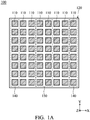
- FIG. 1A is a top view of a conventional antenna array 100.
- the conventional antenna array 100 includes a plurality of antenna elements 110.
- the antenna elements 110 are arranged to form a square shape (or a rectangular shape).
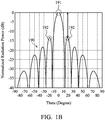
- FIG. 1B is diagram of the radiation pattern 190 of the conventional antenna array 100.
- the horizontal axis represents the zenith angle (Theta), and the vertical axis represents the normalized radiation power.
- the radiation pattern 190 of the antenna array 100 includes a main lobe 191 and a side lobe 192.
- the main lobe 191 is higher than the side lobe 192 by only about 13dB, which is worse than the general standard of 18dB.
- the drawback of the conventional antenna array 100 is directed to the poor side lobe suppression ratio, thereby negatively affecting the spatial efficiency of the conventional antenna array 100.
- a designer can fine-tune the output power of the antenna elements 110.
- a portion of the antenna elements 110 within the central region 130 of the antenna array 100 may have relatively high output power, and another portion of the antenna elements 110 within the edge region 140 of the antenna array 100 may have relatively low output power.
- the aforementioned non-uniform distribution of the output power can increase the side lobe suppression ratio; however, it may decrease the communication distance of the conventional antenna array 100. Accordingly, there is a need to propose a novel solution for solving the problems of the prior art.
- the disclosure is directed to an antenna array including a plurality of antenna elements disposed on the same plane.
- the antenna elements are arranged to form a symmetrical pattern.
- the symmetrical pattern is neither square nor rectangular.
- the antenna elements have the same output power.
- the radiation pattern of the antenna array includes a main lobe and a side lobe.
- the main lobe is higher than the side lobe by at least 18dB.
- the antenna array covers an operation frequency band from 27GHz to 29GHz.
- the distance between any adjacent two of the antenna elements is shorter than or equal to 0.5 wavelength of the operation frequency band.
- the symmetrical pattern substantially has a regular hexagonal shape, and the antenna elements are distributed over the periphery and the interior of the regular hexagonal shape.
- the regular hexagonal shape is divided into a first straight line, a second straight line, a third straight line, a fourth straight line, a fifth straight line, a sixth straight line, a seventh straight line, an eighth straight line, and a ninth straight line which are substantially parallel to each other.
- the antenna elements are arranged on the first straight line
- six of the antenna elements are arranged on the second straight line
- seven of the antenna elements are arranged on the third straight line
- eight of the antenna elements are arranged on the fourth straight line
- nine of the antenna elements are arranged on the fifth straight line
- eight of the antenna elements are arranged on the sixth straight line
- seven of the antenna elements are arranged on the seventh straight line
- six of the antenna elements are arranged on the eighth straight line
- five of the antenna elements are arranged on the ninth straight line.
- the symmetrical pattern substantially has a concentric circular shape, and the antenna elements are distributed over the periphery and the interior of the concentric circular shape.
- the concentric circular shape is divided into a first circumference, a second circumference, a third circumference, a fourth circumference, and a fifth circumference, all of which have the same center.
- one of the antenna elements is arranged at the center of the circle, four of the antenna elements are arranged on the first circumference, eight of the antenna elements are arranged on the second circumference, twelve of the antenna elements are arranged on the third circumference, sixteen of the antenna elements are arranged on the fourth circumference, and twenty of the antenna elements are arranged on the fifth circumference.
- the symmetrical pattern substantially has a diamond shape, and the antenna elements are distributed over the periphery and the interior of the diamond shape.
- the antenna elements over the diamond shape are arranged according to binomial coefficients.
- the diamond shape is divided into a first straight line, a second straight line, and a third straight line which are substantially parallel to each other.
- one of the antenna elements is arranged on the first straight line, two of the antenna elements are arranged on the second straight line, and one of the antenna elements is arranged on the third straight line.
- the diamond shape is divided into a first straight line, a second straight line, a third straight line, and a fourth straight line which are substantially parallel to each other.
- one of the antenna elements is arranged on the first straight line, three of the antenna elements are arranged on the second straight line, three of the antenna elements are arranged on the third straight line, and one of the antenna elements is arranged on the fourth straight line.
- the diamond shape is divided into a first straight line, a second straight line, a third straight line, a fourth straight line, and a fifth straight line which are substantially parallel to each other.
- one of the antenna elements is arranged on the first straight line, four of the antenna elements are arranged on the second straight line, six of the antenna elements are arranged on the third straight line, four of the antenna elements are arranged on the fourth straight line, and one of the antenna elements is arranged on the fifth straight line.
- the diamond shape is divided into a first straight line, a second straight line, a third straight line, a fourth straight line, a fifth straight line, and a sixth straight line which are substantially parallel to each other.
- one of the antenna elements is arranged on the first straight line, five of the antenna elements are arranged on the second straight line, ten of the antenna elements are arranged on the third straight line, ten of the antenna elements are arranged on the fourth straight line, five of the antenna elements are arranged on the fifth straight line, and one of the antenna elements is arranged on the sixth straight line.
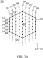
- FIG. 2A is a top view of an antenna array 200 according to an embodiment of the invention.
- the antenna array 200 includes a plurality of antenna elements 210, which are all disposed on the same plane.
- each antenna element 210 is represented by a black dot.
- the shapes and types of the antenna elements 210 are not limited in the invention.
- each of the antenna elements 210 may be a patch antenna, a monopole antenna, a dipole antenna, a bowtie antenna, a loop antenna, a helical antenna, or a chip antenna, but it is not limited thereto.
- the antenna elements 210 are arranged to form a symmetrical pattern 220.
- each of the antenna elements 210 may receive the same feeding signal power from a corresponding signal source or a corresponding power amplifier (not shown), and therefore these antenna elements 210 can provide equalized output power.
- the symmetrical pattern 220 substantially has a regular hexagonal shape, and the antenna elements 210 are distributed over the periphery and the interior of the regular hexagonal shape.
- a portion of the antenna elements 210 inside the symmetrical pattern 220 may be uniformly distributed.
- the regular hexagonal shape may be divided into a first straight line 231, a second straight line 232, a third straight line 233, a fourth straight line 234, a fifth straight line 235, a sixth straight line 236, a seventh straight line 237, an eighth straight line 238, and a ninth straight line 239 which are substantially parallel to each other.
- the total number of antenna elements 210 of the antenna array 200 may be 61.
- antenna elements 210 There may be 5 antenna elements 210 arranged on the first straight line 231. There may be 6 antenna elements 210 arranged on the second straight line 232. There may be 7 antenna elements 210 arranged on the third straight line 233. There may be 8 antenna elements 210 arranged on the fourth straight line 234. There may be 9 antenna elements 210 arranged on the fifth straight line 235. There may be 8 antenna elements 210 arranged on the sixth straight line 236. There may be 7 antenna elements 210 arranged on the seventh straight line 237. There may be 6 antenna elements 210 arranged on the eighth straight line 238. There may be 5 antenna elements 210 arranged on the ninth straight line 239. It should be understood that the above arrangement numbers of antenna elements 210 are merely exemplary, and they may be adjusted to meet different requirements.
- the antenna array 200 covers an operation frequency band from 27GHz to 29GHz, so as to support the wideband operation of 5G millimeter-wave systems.
- the distance D1 between any adjacent two of the first straight line 231, the second straight line 232, the third straight line 233, the fourth straight line 234, the fifth straight line 235, the sixth straight line 236, the seventh straight line 237, the eighth straight line 238, and the ninth straight line 239 may be the same.
- the antenna elements 210 almost form a honeycomb pattern, and thus the distance DA1 between any two adjacent antenna elements 210 may be the same.
- the aforementioned distance DA1 may be shorter than or equal to 0.5 wavelength ( ⁇ /2) of the operation frequency band of the antenna array 200.
- the above ranges of distances are calculated and obtained according to many experiment results, and they help to optimize the side lobe suppression ration of the antenna array 200.
- FIG. 2B is a diagram of a radiation pattern 290 of the antenna array 200 according to an embodiment of the invention.
- the horizontal axis represents the zenith angle (Theta), and the vertical axis represents the normalized radiation power.
- the radiation pattern 290 of the antenna array 200 includes a main lobe 291 and a side lobe 292.
- the main lobe 291 is higher than the side lobe 292 by about 19.4dB, which is better than the general standard of 18dB.
- the EIRP Equivalent Isotropic Radiated Power
- FIG. 3A is a top view of an antenna array 300 according to an embodiment of the invention.
- the antenna array 300 includes a plurality of antenna elements 310, which are all disposed on the same plane.
- the antenna elements 310 are arranged to form a symmetrical pattern 320, which is neither square nor rectangular.
- the antenna elements 310 have the same output power.
- the symmetrical pattern 320 substantially has a concentric circular shape, and the antenna elements 310 are distributed over the periphery and the interior of the concentric circular shape. For example, a portion of the antenna elements 310 inside the symmetrical pattern 320 may be uniformly distributed.
- the concentric circular shape may be divided into a first circumference 331, a second circumference 332, a third circumference 333, a fourth circumference 334, and a fifth circumference 335 which share a center 339 of a circle.
- the total number of antenna elements 310 of the antenna array 300 may be 61.
- antenna elements 310 There may be 12 antenna elements arranged on the third circumference 333, and the distance between any two adjacent antenna elements 310 on the third circumference 333 may be the same. There may be 16 antenna elements arranged on the fourth circumference 334, and the distance between any two adjacent antenna elements 310 on the fourth circumference 334 may be the same. There may be 20 antenna elements arranged on the fifth circumference 335, and the distance between any two adjacent antenna elements 310 on the fifth circumference 335 may be the same. It should be understood that the above arrangement numbers of antenna elements 310 are merely exemplary, and they may be adjusted to meet different requirements.
- the antenna array 300 covers an operation frequency band from 27GHz to 29GHz, so as to support the wideband operation of 5G millimeter-wave systems.
- the distance D2 between any adjacent two of the center 339, the first circumference 331, the second circumference 332, the third circumference 333, the fourth circumference 334, and the fifth circumference 335 may be the same.
- the distance DA2 between any two adjacent antenna elements 310 may be shorter than or equal to 0.5 wavelength ( ⁇ /2) of the operation frequency band of the antenna array 300.
- the above ranges of distances are calculated and obtained according to many experiment results, and they help to optimize the side lobe suppression ration of the antenna array 300.
- FIG. 3B is a diagram of a radiation pattern 390 of the antenna array 300 according to an embodiment of the invention.
- the horizontal axis represents the zenith angle (Theta), and the vertical axis represents the normalized radiation power.
- the radiation pattern 390 of the antenna array 300 includes a main lobe 391 and a side lobe 392.
- the main lobe 391 is higher than the side lobe 392 by about 21dB, which is better than the general standard of 18dB.
- the EIRP of the antenna array 300 is higher than that of the conventional antenna array 100 by about 2.8dB, and the communication distance of the antenna array 300 is longer than that of the conventional antenna array 100 by about 38%.
- Other features of the antenna array 300 of FIG. 3A and FIG. 3B are similar to those of the antenna array 200 of FIG. 2A and FIG. 2B . Therefore, the two embodiments can achieve similar levels of performance.
- adjustments are made such that the aforementioned symmetrical pattern 220 or 320 has a regular pentagonal shape, a regular heptagonal shape, a regular octagonal shape, a regular enneagonal shape, or a regular decagonal shape, but it is not limited thereto.
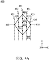
- FIG. 4A is a top view of an antenna array 400 according to an embodiment of the invention.
- the antenna array 400 includes a plurality of antenna elements 410, which are all disposed on the same plane.
- the antenna elements 410 are arranged to form a symmetrical pattern 420, which is neither square nor rectangular.
- the antenna elements 410 have the same output power.
- the symmetrical pattern 420 substantially has a diamond shape, and the antenna elements 410 are distributed over the periphery and the interior of the diamond shape. For example, a portion of the antenna elements 410 inside the symmetrical pattern 420 may be uniformly distributed.
- the diamond shape of the symmetrical pattern 420 may be divided into a first straight line 431, a second straight line 432, a third straight line 433, a fourth straight line 434, and a fifth straight line 435, which are substantially parallel to each other.
- the total number of antenna elements 410 of the antenna array 400 may be 16.
- antenna elements 410 There may be 4 antenna elements 410 arranged on the fourth straight line 434, and the distance between any two adjacent antenna elements 410 on the fourth straight line 434 may be the same. There may be 1 antenna element 410 arranged on the fifth straight line 435. It should be understood that the above arrangement numbers of antenna elements 410 are merely exemplary, and they may be adjusted to meet different requirements.
- the antenna array 400 covers an operation frequency band from 27GHz to 29GHz, so as to support the wideband operation of 5G millimeter-wave systems.
- the distance D2 between any adjacent two of the first straight line 431, the second straight line 432, the third straight line 433, the fourth straight line 434, and the fifth straight line 435 may be the same.
- the distance DA3 between any two adjacent antenna elements 410 may be shorter than or equal to 0.5 wavelength ( ⁇ /2) of the operation frequency band of the antenna array 400.
- the above ranges of distances are calculated and obtained according to many experiment results, and they help to optimize the side lobe suppression ration of the antenna array 400.
- FIG. 4B is a diagram of a radiation pattern 490 of the antenna array 400 according to an embodiment of the invention.
- the horizontal axis represents the zenith angle (Theta), and the vertical axis represents the normalized radiation power.
- the radiation pattern 490 of the antenna array 400 includes a main lobe 491 and a side lobe 492.
- the main lobe 491 is higher than the side lobe 492 by at least 40dB or more, which is better than the general standard of 18dB. It should be noted that the side lobe 492 of the radiation pattern 490 is almost eliminated in comparison to the main lobe 491.
- the EIRP of the antenna array 400 is higher than that of the conventional antenna array 100 by about 5.5dB, and the communication distance of the antenna array 400 is longer than that of the conventional antenna array 100 by about 87.5%.
- Other features of the antenna array 400 of FIG. 4A and FIG. 4B are similar to those of the antenna array 200 of FIG. 2A and FIG. 2B . Therefore, the two embodiments can achieve similar levels of performance.
- FIG. 5 is a top view of an antenna array 500 according to an embodiment of the invention.
- the antenna array 500 includes a plurality of antenna elements 510, which are all disposed on the same plane.
- the antenna elements 510 are arranged to form a symmetrical pattern 520, which is neither square nor rectangular.
- the antenna elements 510 have the same output power.
- the symmetrical pattern 520 substantially has a diamond shape.
- the diamond shape of the symmetrical pattern 520 may be divided into a first straight line 531, a second straight line 532, and a third straight line 533, which are substantially parallel to each other.
- the total number of antenna elements 510 of the antenna array 500 may be 4.
- antenna element 510 There may be 1 antenna element 510 arranged on the first straight line 531. There may be 2 antenna elements 510 arranged on the second straight line 532. There may be 1 antenna element 510 arranged on the third straight line 533.
- Other features of the antenna array 500 of FIG. 5 are similar to those of the antenna array 400 of FIG. 4A and FIG. 4B . Therefore, the two embodiments can achieve similar levels of performance.
- FIG. 6 is a top view of an antenna array 600 according to an embodiment of the invention.
- the antenna array 600 includes a plurality of antenna elements 610, which are all disposed on the same plane.
- the antenna elements 610 are arranged to form a symmetrical pattern 620, which is neither square nor rectangular.
- the antenna elements 610 have the same output power.
- the symmetrical pattern 620 substantially has a diamond shape.
- the diamond shape of the symmetrical pattern 620 may be divided into a first straight line 631, a second straight line 632, a third straight line 633, and a fourth straight line 634, which are substantially parallel to each other.
- the total number of antenna elements 610 of the antenna array 600 may be 8.
- antenna element 610 There may be 1 antenna element 610 arranged on the first straight line 631. There may be 3 antenna elements 610 arranged on the second straight line 632, and the distance between any two adjacent antenna elements 610 on the second straight line 632 may be the same. There may be 3 antenna elements 610 arranged on the third straight line 633, and the distance between any two adjacent antenna elements 610 on the third straight line 633 may be the same. There may be 1 antenna element 610 arranged on the fourth straight line 634. Other features of the antenna array 600 of FIG. 6 are similar to those of the antenna array 400 of FIG. 4A and FIG. 4B . Therefore, the two embodiments can achieve similar levels of performance.
- FIG. 7 is a top view of an antenna array 700 according to an embodiment of the invention.
- the antenna array 700 includes a plurality of antenna elements 710, which are all disposed on the same plane.
- the antenna elements 710 are arranged to form a symmetrical pattern 720, which is neither square nor rectangular.
- the antenna elements 710 have the same output power.
- the symmetrical pattern 720 substantially has a diamond shape. Specifically, the diamond shape of the symmetrical pattern 720 may be divided into a first straight line 731, a second straight line 732, a third straight line 733, a fourth straight line 734, a fifth straight line 735, and a sixth straight line 736, which are substantially parallel to each other.
- the total number of antenna elements 710 of the antenna array 700 may be 32. There may be 1 antenna element 710 arranged on the first straight line 731. There may be 5 antenna elements 710 arranged on the second straight line 732, and the distance between any two adjacent antenna elements 710 on the second straight line 732 may be the same. There may be 10 antenna elements 710 arranged on the third straight line 733, and the distance between any two adjacent antenna elements 710 on the third straight line 733 may be the same. There may be 10 antenna elements 710 arranged on the fourth straight line 734, and the distance between any two adjacent antenna elements 710 on the fourth straight line 734 may be the same.
- antenna elements 710 There may be 5 antenna elements 710 arranged on the fifth straight line 735, and the distance between any two adjacent antenna elements 710 on the fifth straight line 735 may be the same. There may be 1 antenna element 710 arranged on the sixth straight line 736.
- Other features of the antenna array 700 of FIG. 7 are similar to those of the antenna array 400 of FIG. 4A and FIG. 4B . Therefore, the two embodiments can achieve similar levels of performance.
- the antenna elements over the diamond shape of each symmetrical pattern are arranged according to binomial coefficients. If such a diamond shape is divided into N parallel straight lines, the number of antenna elements arranged on the k-th straight line will be represented as C k ⁇ 1 N ⁇ 1 For example, if 5 parallel straight lines are applied, there will be 1 C 0 4 , 4 C 1 4 , 6 C 2 4 , 4 C 3 4 , and 1 C 4 4 antenna element(s) arranged on the first, second, third, fourth, and fifth straight lines, respectively. In alternative embodiments, more antenna elements may be designed over the aforementioned diamond shape, and therefore the corresponding antenna array can generate a longer communication distance.
- the invention proposes a novel antenna array, whose antenna elements are arranged to form a non-rectangular symmetrical pattern. Each antenna element has equal output power.
- the invention has at least the advantages of suppressing the side lobe and increasing the communication distance, and therefore it is suitable for application in a variety of communication devices to improve the communication distance and the spatial efficiency.
- the antenna array of the invention is not limited to the configurations of FIGS. 1-7 .
- the invention may merely include any one or more features of any one or more embodiments of FIGS. 1-7 . In other words, not all of the features displayed in the figures should be implemented in the antenna array of the invention.
Landscapes
- Variable-Direction Aerials And Aerial Arrays (AREA)
Abstract
Description
- This application claims priority of China Patent Application No.
201910672643.3 filed on July 24, 2019 - The disclosure generally relates to an antenna array, and more particularly, it relates to an antenna array for suppressing the side lobe and increasing the communication distance.
-
FIG. 1A is a top view of aconventional antenna array 100. As shown inFIG. 1A , theconventional antenna array 100 includes a plurality ofantenna elements 110. Theantenna elements 110 are arranged to form a square shape (or a rectangular shape). -
FIG. 1B is diagram of theradiation pattern 190 of theconventional antenna array 100. The horizontal axis represents the zenith angle (Theta), and the vertical axis represents the normalized radiation power. As shown inFIG. 1B , theradiation pattern 190 of theantenna array 100 includes amain lobe 191 and aside lobe 192. Themain lobe 191 is higher than theside lobe 192 by only about 13dB, which is worse than the general standard of 18dB. The drawback of theconventional antenna array 100 is directed to the poor side lobe suppression ratio, thereby negatively affecting the spatial efficiency of theconventional antenna array 100. - In order to improve the side lobe suppression ratio, a designer can fine-tune the output power of the
antenna elements 110. For example, a portion of theantenna elements 110 within thecentral region 130 of theantenna array 100 may have relatively high output power, and another portion of theantenna elements 110 within theedge region 140 of theantenna array 100 may have relatively low output power. The aforementioned non-uniform distribution of the output power can increase the side lobe suppression ratio; however, it may decrease the communication distance of theconventional antenna array 100. Accordingly, there is a need to propose a novel solution for solving the problems of the prior art. - In an exemplary embodiment, the disclosure is directed to an antenna array including a plurality of antenna elements disposed on the same plane. The antenna elements are arranged to form a symmetrical pattern. The symmetrical pattern is neither square nor rectangular. The antenna elements have the same output power.
- In some embodiments, the radiation pattern of the antenna array includes a main lobe and a side lobe. The main lobe is higher than the side lobe by at least 18dB.
- In some embodiments, the antenna array covers an operation frequency band from 27GHz to 29GHz.
- In some embodiments, the distance between any adjacent two of the antenna elements is shorter than or equal to 0.5 wavelength of the operation frequency band.
- In some embodiments, the symmetrical pattern substantially has a regular hexagonal shape, and the antenna elements are distributed over the periphery and the interior of the regular hexagonal shape.
- In some embodiments, the regular hexagonal shape is divided into a first straight line, a second straight line, a third straight line, a fourth straight line, a fifth straight line, a sixth straight line, a seventh straight line, an eighth straight line, and a ninth straight line which are substantially parallel to each other.
- In some embodiments, five of the antenna elements are arranged on the first straight line, six of the antenna elements are arranged on the second straight line, seven of the antenna elements are arranged on the third straight line, eight of the antenna elements are arranged on the fourth straight line, nine of the antenna elements are arranged on the fifth straight line, eight of the antenna elements are arranged on the sixth straight line, seven of the antenna elements are arranged on the seventh straight line, six of the antenna elements are arranged on the eighth straight line, and five of the antenna elements are arranged on the ninth straight line.
- In some embodiments, the symmetrical pattern substantially has a concentric circular shape, and the antenna elements are distributed over the periphery and the interior of the concentric circular shape.
- In some embodiments, the concentric circular shape is divided into a first circumference, a second circumference, a third circumference, a fourth circumference, and a fifth circumference, all of which have the same center.
- In some embodiments, one of the antenna elements is arranged at the center of the circle, four of the antenna elements are arranged on the first circumference, eight of the antenna elements are arranged on the second circumference, twelve of the antenna elements are arranged on the third circumference, sixteen of the antenna elements are arranged on the fourth circumference, and twenty of the antenna elements are arranged on the fifth circumference.
- In some embodiments, the symmetrical pattern substantially has a diamond shape, and the antenna elements are distributed over the periphery and the interior of the diamond shape.
- In some embodiments, the antenna elements over the diamond shape are arranged according to binomial coefficients.
- In some embodiments, the diamond shape is divided into a first straight line, a second straight line, and a third straight line which are substantially parallel to each other.
- In some embodiments, one of the antenna elements is arranged on the first straight line, two of the antenna elements are arranged on the second straight line, and one of the antenna elements is arranged on the third straight line.
- In some embodiments, the diamond shape is divided into a first straight line, a second straight line, a third straight line, and a fourth straight line which are substantially parallel to each other.
- In some embodiments, one of the antenna elements is arranged on the first straight line, three of the antenna elements are arranged on the second straight line, three of the antenna elements are arranged on the third straight line, and one of the antenna elements is arranged on the fourth straight line.
- In some embodiments, the diamond shape is divided into a first straight line, a second straight line, a third straight line, a fourth straight line, and a fifth straight line which are substantially parallel to each other.
- In some embodiments, one of the antenna elements is arranged on the first straight line, four of the antenna elements are arranged on the second straight line, six of the antenna elements are arranged on the third straight line, four of the antenna elements are arranged on the fourth straight line, and one of the antenna elements is arranged on the fifth straight line.
- In some embodiments, the diamond shape is divided into a first straight line, a second straight line, a third straight line, a fourth straight line, a fifth straight line, and a sixth straight line which are substantially parallel to each other.
- In some embodiments, one of the antenna elements is arranged on the first straight line, five of the antenna elements are arranged on the second straight line, ten of the antenna elements are arranged on the third straight line, ten of the antenna elements are arranged on the fourth straight line, five of the antenna elements are arranged on the fifth straight line, and one of the antenna elements is arranged on the sixth straight line.
- The invention can be more fully understood by reading the subsequent detailed description and examples with references made to the accompanying drawings, wherein:
-
FIG. 1A is a top view of a conventional antenna array; -
FIG. 1B is diagram of a radiation pattern of a conventional antenna array; -
FIG. 2A is a top view of an antenna array according to an embodiment of the invention; -
FIG. 2B is a diagram of a radiation pattern of an antenna array according to an embodiment of the invention; -
FIG. 3A is a top view of an antenna array according to an embodiment of the invention; -
FIG. 3B is a diagram of a radiation pattern of an antenna array according to an embodiment of the invention; -
FIG. 4A is a top view of an antenna array according to an embodiment of the invention; -
FIG. 4B is a diagram of a radiation pattern of an antenna array according to an embodiment of the invention; -
FIG. 5 is a top view of an antenna array according to an embodiment of the invention; -
FIG. 6 is a top view of an antenna array according to an embodiment of the invention; and -
FIG. 7 is a top view of an antenna array according to an embodiment of the invention. - In order to illustrate the purposes, features and advantages of the invention, the embodiments and figures of the invention are shown in detail as follows.
- Certain terms are used throughout the description and following claims to refer to particular components. As one skilled in the art will appreciate, manufacturers may refer to a component by different names. This document does not intend to distinguish between components that differ in name but not function. In the following description and in the claims, the terms "include" and "comprise" are used in an open-ended fashion, and thus should be interpreted to mean "include, but not limited to...". The term "substantially" means the value is within an acceptable error range. One skilled in the art can solve the technical problem within a predetermined error range and achieve the proposed technical performance. Also, the term "couple" is intended to mean either an indirect or direct electrical connection. Accordingly, if one device is coupled to another device, that connection may be through a direct electrical connection, or through an indirect electrical connection via other devices and connections.
-
FIG. 2A is a top view of anantenna array 200 according to an embodiment of the invention. As shown inFIG. 2A , theantenna array 200 includes a plurality ofantenna elements 210, which are all disposed on the same plane. To simplify the figure, eachantenna element 210 is represented by a black dot. The shapes and types of theantenna elements 210 are not limited in the invention. For example, each of theantenna elements 210 may be a patch antenna, a monopole antenna, a dipole antenna, a bowtie antenna, a loop antenna, a helical antenna, or a chip antenna, but it is not limited thereto. Theantenna elements 210 are arranged to form asymmetrical pattern 220. The difference from the conventional design is that thesymmetrical pattern 220 is neither square nor rectangular. In addition, it should be noted that theantenna elements 210 have the same output power. That is, each of theantenna elements 210 may receive the same feeding signal power from a corresponding signal source or a corresponding power amplifier (not shown), and therefore theseantenna elements 210 can provide equalized output power. - In the embodiment of
FIG. 2A , thesymmetrical pattern 220 substantially has a regular hexagonal shape, and theantenna elements 210 are distributed over the periphery and the interior of the regular hexagonal shape. For example, a portion of theantenna elements 210 inside thesymmetrical pattern 220 may be uniformly distributed. Specifically, the regular hexagonal shape may be divided into a firststraight line 231, a secondstraight line 232, a thirdstraight line 233, a fourthstraight line 234, a fifthstraight line 235, a sixthstraight line 236, a seventhstraight line 237, an eighthstraight line 238, and a ninthstraight line 239 which are substantially parallel to each other. For example, the total number ofantenna elements 210 of theantenna array 200 may be 61. There may be 5antenna elements 210 arranged on the firststraight line 231. There may be 6antenna elements 210 arranged on the secondstraight line 232. There may be 7antenna elements 210 arranged on the thirdstraight line 233. There may be 8antenna elements 210 arranged on the fourthstraight line 234. There may be 9antenna elements 210 arranged on the fifthstraight line 235. There may be 8antenna elements 210 arranged on the sixthstraight line 236. There may be 7antenna elements 210 arranged on the seventhstraight line 237. There may be 6antenna elements 210 arranged on the eighthstraight line 238. There may be 5antenna elements 210 arranged on the ninthstraight line 239. It should be understood that the above arrangement numbers ofantenna elements 210 are merely exemplary, and they may be adjusted to meet different requirements. - In some embodiments, the
antenna array 200 covers an operation frequency band from 27GHz to 29GHz, so as to support the wideband operation of 5G millimeter-wave systems. With respect to the elements sizes, the distance D1 between any adjacent two of the firststraight line 231, the secondstraight line 232, the thirdstraight line 233, the fourthstraight line 234, the fifthstraight line 235, the sixthstraight line 236, the seventhstraight line 237, the eighthstraight line 238, and the ninthstraight line 239 may be the same. Generally, theantenna elements 210 almost form a honeycomb pattern, and thus the distance DA1 between any twoadjacent antenna elements 210 may be the same. For example, the aforementioned distance DA1 may be shorter than or equal to 0.5 wavelength (λ/2) of the operation frequency band of theantenna array 200. The above ranges of distances are calculated and obtained according to many experiment results, and they help to optimize the side lobe suppression ration of theantenna array 200. -
FIG. 2B is a diagram of aradiation pattern 290 of theantenna array 200 according to an embodiment of the invention. The horizontal axis represents the zenith angle (Theta), and the vertical axis represents the normalized radiation power. According to the measurement ofFIG. 2B , theradiation pattern 290 of theantenna array 200 includes amain lobe 291 and aside lobe 292. Themain lobe 291 is higher than theside lobe 292 by about 19.4dB, which is better than the general standard of 18dB. Furthermore, since theantenna elements 210 have the same output power, the EIRP (Equivalent Isotropic Radiated Power) of theantenna array 200 is higher than that of theconventional antenna array 100 by about 2.5dB, and the communication distance of theantenna array 200 is longer than that of theconventional antenna array 100 by about 33%. -
FIG. 3A is a top view of anantenna array 300 according to an embodiment of the invention. As shown inFIG. 3A , theantenna array 300 includes a plurality ofantenna elements 310, which are all disposed on the same plane. Theantenna elements 310 are arranged to form asymmetrical pattern 320, which is neither square nor rectangular. Theantenna elements 310 have the same output power. In the embodiment ofFIG. 3A , thesymmetrical pattern 320 substantially has a concentric circular shape, and theantenna elements 310 are distributed over the periphery and the interior of the concentric circular shape. For example, a portion of theantenna elements 310 inside thesymmetrical pattern 320 may be uniformly distributed. Specifically, the concentric circular shape may be divided into afirst circumference 331, asecond circumference 332, athird circumference 333, afourth circumference 334, and afifth circumference 335 which share acenter 339 of a circle. For example, the total number ofantenna elements 310 of theantenna array 300 may be 61. There may be 1 antenna element arranged at thecenter 339 of the circle. There may be 4 antenna elements arranged on thefirst circumference 331, and the distance between any twoadjacent antenna elements 310 on thefirst circumference 331 may be the same. There may be 8 antenna elements arranged on thesecond circumference 332, and the distance between any twoadjacent antenna elements 310 on thesecond circumference 332 may be the same. There may be 12 antenna elements arranged on thethird circumference 333, and the distance between any twoadjacent antenna elements 310 on thethird circumference 333 may be the same. There may be 16 antenna elements arranged on thefourth circumference 334, and the distance between any twoadjacent antenna elements 310 on thefourth circumference 334 may be the same. There may be 20 antenna elements arranged on thefifth circumference 335, and the distance between any twoadjacent antenna elements 310 on thefifth circumference 335 may be the same. It should be understood that the above arrangement numbers ofantenna elements 310 are merely exemplary, and they may be adjusted to meet different requirements. - In some embodiments, the
antenna array 300 covers an operation frequency band from 27GHz to 29GHz, so as to support the wideband operation of 5G millimeter-wave systems. With respect to the elements sizes, the distance D2 between any adjacent two of thecenter 339, thefirst circumference 331, thesecond circumference 332, thethird circumference 333, thefourth circumference 334, and thefifth circumference 335 may be the same. The distance DA2 between any twoadjacent antenna elements 310 may be shorter than or equal to 0.5 wavelength (λ/2) of the operation frequency band of theantenna array 300. The above ranges of distances are calculated and obtained according to many experiment results, and they help to optimize the side lobe suppression ration of theantenna array 300. -
FIG. 3B is a diagram of aradiation pattern 390 of theantenna array 300 according to an embodiment of the invention. The horizontal axis represents the zenith angle (Theta), and the vertical axis represents the normalized radiation power. According to the measurement ofFIG. 3B , theradiation pattern 390 of theantenna array 300 includes amain lobe 391 and aside lobe 392. Themain lobe 391 is higher than theside lobe 392 by about 21dB, which is better than the general standard of 18dB. Furthermore, since theantenna elements 310 have the same output power, the EIRP of theantenna array 300 is higher than that of theconventional antenna array 100 by about 2.8dB, and the communication distance of theantenna array 300 is longer than that of theconventional antenna array 100 by about 38%. Other features of theantenna array 300 ofFIG. 3A andFIG. 3B are similar to those of theantenna array 200 ofFIG. 2A andFIG. 2B . Therefore, the two embodiments can achieve similar levels of performance. - In alternative embodiments, adjustments are made such that the aforementioned
symmetrical pattern -
FIG. 4A is a top view of anantenna array 400 according to an embodiment of the invention. As shown inFIG. 4A , theantenna array 400 includes a plurality ofantenna elements 410, which are all disposed on the same plane. Theantenna elements 410 are arranged to form asymmetrical pattern 420, which is neither square nor rectangular. Theantenna elements 410 have the same output power. In the embodiment ofFIG. 4A , thesymmetrical pattern 420 substantially has a diamond shape, and theantenna elements 410 are distributed over the periphery and the interior of the diamond shape. For example, a portion of theantenna elements 410 inside thesymmetrical pattern 420 may be uniformly distributed. Specifically, the diamond shape of thesymmetrical pattern 420 may be divided into a firststraight line 431, a secondstraight line 432, a thirdstraight line 433, a fourthstraight line 434, and a fifthstraight line 435, which are substantially parallel to each other. For example, the total number ofantenna elements 410 of theantenna array 400 may be 16. There may be 1antenna element 410 arranged on the firststraight line 431. There may be 4antenna elements 410 arranged on the secondstraight line 432, and the distance between any twoadjacent antenna elements 410 on the secondstraight line 432 may be the same. There may be 6antenna elements 410 arranged on the thirdstraight line 433, and the distance between any twoadjacent antenna elements 410 on the thirdstraight line 433 may be the same. There may be 4antenna elements 410 arranged on the fourthstraight line 434, and the distance between any twoadjacent antenna elements 410 on the fourthstraight line 434 may be the same. There may be 1antenna element 410 arranged on the fifthstraight line 435. It should be understood that the above arrangement numbers ofantenna elements 410 are merely exemplary, and they may be adjusted to meet different requirements. - In some embodiments, the
antenna array 400 covers an operation frequency band from 27GHz to 29GHz, so as to support the wideband operation of 5G millimeter-wave systems. With respect to the elements sizes, the distance D2 between any adjacent two of the firststraight line 431, the secondstraight line 432, the thirdstraight line 433, the fourthstraight line 434, and the fifthstraight line 435 may be the same. The distance DA3 between any twoadjacent antenna elements 410 may be shorter than or equal to 0.5 wavelength (λ/2) of the operation frequency band of theantenna array 400. The above ranges of distances are calculated and obtained according to many experiment results, and they help to optimize the side lobe suppression ration of theantenna array 400. -
FIG. 4B is a diagram of aradiation pattern 490 of theantenna array 400 according to an embodiment of the invention. The horizontal axis represents the zenith angle (Theta), and the vertical axis represents the normalized radiation power. According to the measurement ofFIG. 4B , theradiation pattern 490 of theantenna array 400 includes amain lobe 491 and aside lobe 492. Themain lobe 491 is higher than theside lobe 492 by at least 40dB or more, which is better than the general standard of 18dB. It should be noted that theside lobe 492 of theradiation pattern 490 is almost eliminated in comparison to themain lobe 491. Furthermore, since theantenna elements 410 have the same output power, the EIRP of theantenna array 400 is higher than that of theconventional antenna array 100 by about 5.5dB, and the communication distance of theantenna array 400 is longer than that of theconventional antenna array 100 by about 87.5%. Other features of theantenna array 400 ofFIG. 4A andFIG. 4B are similar to those of theantenna array 200 ofFIG. 2A andFIG. 2B . Therefore, the two embodiments can achieve similar levels of performance. -
FIG. 5 is a top view of anantenna array 500 according to an embodiment of the invention. As shown inFIG. 5 , theantenna array 500 includes a plurality ofantenna elements 510, which are all disposed on the same plane. Theantenna elements 510 are arranged to form asymmetrical pattern 520, which is neither square nor rectangular. Theantenna elements 510 have the same output power. In the embodiment ofFIG. 5 , thesymmetrical pattern 520 substantially has a diamond shape. Specifically, the diamond shape of thesymmetrical pattern 520 may be divided into a firststraight line 531, a secondstraight line 532, and a thirdstraight line 533, which are substantially parallel to each other. For example, the total number ofantenna elements 510 of theantenna array 500 may be 4. There may be 1antenna element 510 arranged on the firststraight line 531. There may be 2antenna elements 510 arranged on the secondstraight line 532. There may be 1antenna element 510 arranged on the thirdstraight line 533. Other features of theantenna array 500 ofFIG. 5 are similar to those of theantenna array 400 ofFIG. 4A andFIG. 4B . Therefore, the two embodiments can achieve similar levels of performance. -
FIG. 6 is a top view of anantenna array 600 according to an embodiment of the invention. As shown inFIG. 6 , theantenna array 600 includes a plurality ofantenna elements 610, which are all disposed on the same plane. Theantenna elements 610 are arranged to form asymmetrical pattern 620, which is neither square nor rectangular. Theantenna elements 610 have the same output power. In the embodiment ofFIG. 6 , thesymmetrical pattern 620 substantially has a diamond shape. Specifically, the diamond shape of thesymmetrical pattern 620 may be divided into a firststraight line 631, a secondstraight line 632, a thirdstraight line 633, and a fourthstraight line 634, which are substantially parallel to each other. For example, the total number ofantenna elements 610 of theantenna array 600 may be 8. There may be 1antenna element 610 arranged on the firststraight line 631. There may be 3antenna elements 610 arranged on the secondstraight line 632, and the distance between any twoadjacent antenna elements 610 on the secondstraight line 632 may be the same. There may be 3antenna elements 610 arranged on the thirdstraight line 633, and the distance between any twoadjacent antenna elements 610 on the thirdstraight line 633 may be the same. There may be 1antenna element 610 arranged on the fourthstraight line 634. Other features of theantenna array 600 ofFIG. 6 are similar to those of theantenna array 400 ofFIG. 4A andFIG. 4B . Therefore, the two embodiments can achieve similar levels of performance. -
FIG. 7 is a top view of anantenna array 700 according to an embodiment of the invention. As shown inFIG. 7 , theantenna array 700 includes a plurality ofantenna elements 710, which are all disposed on the same plane. Theantenna elements 710 are arranged to form asymmetrical pattern 720, which is neither square nor rectangular. Theantenna elements 710 have the same output power. In the embodiment ofFIG. 7 , thesymmetrical pattern 720 substantially has a diamond shape. Specifically, the diamond shape of thesymmetrical pattern 720 may be divided into a firststraight line 731, a secondstraight line 732, a thirdstraight line 733, a fourthstraight line 734, a fifthstraight line 735, and a sixthstraight line 736, which are substantially parallel to each other. For example, the total number ofantenna elements 710 of theantenna array 700 may be 32. There may be 1antenna element 710 arranged on the firststraight line 731. There may be 5antenna elements 710 arranged on the secondstraight line 732, and the distance between any twoadjacent antenna elements 710 on the secondstraight line 732 may be the same. There may be 10antenna elements 710 arranged on the thirdstraight line 733, and the distance between any twoadjacent antenna elements 710 on the thirdstraight line 733 may be the same. There may be 10antenna elements 710 arranged on the fourthstraight line 734, and the distance between any twoadjacent antenna elements 710 on the fourthstraight line 734 may be the same. There may be 5antenna elements 710 arranged on the fifthstraight line 735, and the distance between any twoadjacent antenna elements 710 on the fifthstraight line 735 may be the same. There may be 1antenna element 710 arranged on the sixthstraight line 736. Other features of theantenna array 700 ofFIG. 7 are similar to those of theantenna array 400 ofFIG. 4A andFIG. 4B . Therefore, the two embodiments can achieve similar levels of performance. - Generally, the antenna elements over the diamond shape of each symmetrical pattern are arranged according to binomial coefficients. If such a diamond shape is divided into N parallel straight lines, the number of antenna elements arranged on the k-th straight line will be represented as


- The invention proposes a novel antenna array, whose antenna elements are arranged to form a non-rectangular symmetrical pattern. Each antenna element has equal output power. In comparison to conventional designs, the invention has at least the advantages of suppressing the side lobe and increasing the communication distance, and therefore it is suitable for application in a variety of communication devices to improve the communication distance and the spatial efficiency.
- Note that the above element sizes, element shapes, and frequency ranges are not limitations of the invention. An antenna designer can fine-tune these settings or values to meet different requirements. It should be understood that the antenna array of the invention is not limited to the configurations of
FIGS. 1-7 . The invention may merely include any one or more features of any one or more embodiments ofFIGS. 1-7 . In other words, not all of the features displayed in the figures should be implemented in the antenna array of the invention. - Use of ordinal terms such as "first", "second", "third", etc., in the claims to modify a claim element does not by itself connote any priority, precedence, or order of one claim element over another or the temporal order in which acts of a method are performed, but are used merely as labels to distinguish one claim element having a certain name from another element having the same name (but for use of the ordinal term) to distinguish the claim elements.
- While the invention has been described by way of example and in terms of the preferred embodiments, it should be understood that the invention is not limited to the disclosed embodiments. On the contrary, it is intended to cover various modifications and similar arrangements (as would be apparent to those skilled in the art). Therefore, the scope of the appended claims should be accorded the broadest interpretation so as to encompass all such modifications and similar arrangements.
Claims (15)
- An antenna array, comprising:a plurality of antenna elements, disposed on a plane;wherein the antenna elements are arranged to form a symmetrical pattern, and the symmetrical pattern is neither square nor rectangular;wherein the antenna elements have the same output power.
- The antenna array as claimed in claim 1, wherein a radiation pattern of the antenna array includes a main lobe and a side lobe, and the main lobe is higher than the side lobe by at least 18dB.
- The antenna array as claimed in claim 1 or 2, wherein the antenna array covers an operation frequency band from 27GHz to 29GHz, and a distance between any two adjacent antenna elements is shorter than or equal to 0.5 wavelength of the operation frequency band.
- The antenna array as claimed in one of the preceding claims, wherein the symmetrical pattern substantially has a regular hexagonal shape, and the antenna elements are distributed over a periphery and an interior of the regular hexagonal shape.
- The antenna array as claimed in claim 4, wherein the regular hexagonal shape is divided into a first straight line, a second straight line, a third straight line, a fourth straight line, a fifth straight line, a sixth straight line, a seventh straight line, an eighth straight line, and a ninth straight line which are substantially parallel to each other.
- The antenna array as claimed in claim 5, wherein five of the antenna elements are arranged on the first straight line, six of the antenna elements are arranged on the second straight line, seven of the antenna elements are arranged on the third straight line, eight of the antenna elements are arranged on the fourth straight line, nine of the antenna elements are arranged on the fifth straight line, eight of the antenna elements are arranged on the sixth straight line, seven of the antenna elements are arranged on the seventh straight line, six of the antenna elements are arranged on the eighth straight line, and five of the antenna elements are arranged on the ninth straight line.
- The antenna array as claimed in one of the claims 1-3, wherein the symmetrical pattern substantially has a concentric circular shape, and the antenna elements are distributed over a periphery and an interior of the concentric circular shape.
- The antenna array as claimed in claim 7, wherein the concentric circular shape is divided into a first circumference, a second circumference, a third circumference, a fourth circumference, and a fifth circumference which share a center of a circle.
- The antenna array as claimed in claim 8, wherein one of the antenna elements is arranged at the center of the circle, four of the antenna elements are arranged on the first circumference, eight of the antenna elements are arranged on the second circumference, twelve of the antenna elements are arranged on the third circumference, sixteen of the antenna elements are arranged on the fourth circumference, and twenty of the antenna elements are arranged on the fifth circumference.
- The antenna array as claimed in one of the claims 1-3, wherein the symmetrical pattern substantially has a diamond shape, and the antenna elements are distributed over a periphery and an interior of the diamond shape.
- The antenna array as claimed in claim 10, wherein the antenna elements over the diamond shape are arranged according to binomial coefficients.
- The antenna array as claimed in claim 10 or 11, wherein the diamond shape is divided into a first straight line, a second straight line, and a third straight line which are substantially parallel to each other, and wherein one of the antenna elements is arranged on the first straight line, two of the antenna elements are arranged on the second straight line, and one of the antenna elements is arranged on the third straight line.
- The antenna array as claimed in one of the claims 10-12, wherein the diamond shape is divided into a first straight line, a second straight line, a third straight line, and a fourth straight line which are substantially parallel to each other, and wherein one of the antenna elements is arranged on the first straight line, three of the antenna elements are arranged on the second straight line, three of the antenna elements are arranged on the third straight line, and one of the antenna elements is arranged on the fourth straight line.
- The antenna array as claimed in one of the claims 10-13, wherein the diamond shape is divided into a first straight line, a second straight line, a third straight line, a fourth straight line, and a fifth straight line which are substantially parallel to each other, and wherein one of the antenna elements is arranged on the first straight line, four of the antenna elements are arranged on the second straight line, six of the antenna elements are arranged on the third straight line, four of the antenna elements are arranged on the fourth straight line, and one of the antenna elements is arranged on the fifth straight line.
- The antenna array as claimed in one of the claims 10-14, wherein the diamond shape is divided into a first straight line, a second straight line, a third straight line, a fourth straight line, a fifth straight line, and a sixth straight line which are substantially parallel to each other, and wherein one of the antenna elements is arranged on the first straight line, five of the antenna elements are arranged on the second straight line, ten of the antenna elements are arranged on the third straight line, ten of the antenna elements are arranged on the fourth straight line, five of the antenna elements are arranged on the fifth straight line, and one of the antenna elements is arranged on the sixth straight line.
Applications Claiming Priority (1)
| Application Number | Priority Date | Filing Date | Title |
|---|---|---|---|
| CN201910672643.3A CN112290235A (en) | 2019-07-24 | 2019-07-24 | antenna array |
Publications (3)
| Publication Number | Publication Date |
|---|---|
| EP3771041A1 true EP3771041A1 (en) | 2021-01-27 |
| EP3771041B1 EP3771041B1 (en) | 2025-12-10 |
| EP3771041C0 EP3771041C0 (en) | 2025-12-10 |
Family
ID=68289834
Family Applications (1)
| Application Number | Title | Priority Date | Filing Date |
|---|---|---|---|
| EP19203100.3A Active EP3771041B1 (en) | 2019-07-24 | 2019-10-14 | Antenna array |
Country Status (5)
| Country | Link |
|---|---|
| US (1) | US11063369B2 (en) |
| EP (1) | EP3771041B1 (en) |
| JP (1) | JP6890171B2 (en) |
| CN (1) | CN112290235A (en) |
| ES (1) | ES3058486T3 (en) |
Citations (8)
| Publication number | Priority date | Publication date | Assignee | Title |
|---|---|---|---|---|
| US20030090433A1 (en) * | 2001-02-26 | 2003-05-15 | Masataka Ohtsuka | Antenna device |
| US20050162326A1 (en) * | 2003-01-23 | 2005-07-28 | Pierre Steyn | Antenna |
| US20060132375A1 (en) * | 2004-12-16 | 2006-06-22 | Yang-Su Kim | Device for shaping flat-topped element pattern using circular polarization microstrip patch |
| US7498989B1 (en) * | 2007-04-26 | 2009-03-03 | Lockheed Martin Corporation | Stacked-disk antenna element with wings, and array thereof |
| EP2246934A1 (en) * | 2008-02-29 | 2010-11-03 | Omron Corporation | Array antenna, tag communication device, tag communication system, and beam control method for array antenna |
| US20160282462A1 (en) * | 2015-03-27 | 2016-09-29 | The Boeing Company | Multi-function shared aperture array |
| CN107275803A (en) * | 2017-05-31 | 2017-10-20 | 西安华讯天基通信技术有限公司 | A kind of millimeter wave reflection from lens formula intelligent antenna equipment |
| DE102016014385A1 (en) * | 2016-12-02 | 2018-06-07 | Kathrein-Werke Kg | Dual polarized horn |
Family Cites Families (29)
| Publication number | Priority date | Publication date | Assignee | Title |
|---|---|---|---|---|
| US4353067A (en) * | 1980-08-29 | 1982-10-05 | Westinghouse Electric Corp. | Method of reducing side lobes of complementary coded pulses in a coherent pulse compression doppler radar receiving system |
| JPH0591019U (en) | 1992-05-15 | 1993-12-10 | 日立化成工業株式会社 | Planar array antenna |
| US5283587A (en) * | 1992-11-30 | 1994-02-01 | Space Systems/Loral | Active transmit phased array antenna |
| JP3029003B2 (en) | 1994-02-23 | 2000-04-04 | 久松 中野 | Planar antenna for linear polarization |
| JP4067672B2 (en) | 1998-12-25 | 2008-03-26 | 松下電器産業株式会社 | ANTENNA DEVICE AND RADIO DEVICE AND RADIO RELAY DEVICE USING THE SAME |
| US6404404B1 (en) * | 2000-07-31 | 2002-06-11 | Trw Inc. | Density tapered transmit phased array |
| WO2002103846A1 (en) | 2001-06-15 | 2002-12-27 | E-Tenna Corporation | Aperture antenna having a high-impedance backing |
| JP2007142878A (en) | 2005-11-18 | 2007-06-07 | Ntt Docomo Inc | Multi-antenna device for terminal |
| JP5638827B2 (en) | 2010-04-02 | 2014-12-10 | 古河電気工業株式会社 | Integrated antenna for built-in radar |
| US9030360B2 (en) | 2012-07-26 | 2015-05-12 | Raytheon Company | Electromagnetic band gap structure for enhanced scanning performance in phased array apertures |
| US9515387B2 (en) | 2012-08-17 | 2016-12-06 | Mediatek Inc. | Multi-input multi-output antenna with electromagnetic band-gap structure |
| JP6073713B2 (en) | 2013-03-13 | 2017-02-01 | 株式会社日本自動車部品総合研究所 | Antenna device |
| US20140313080A1 (en) * | 2013-04-19 | 2014-10-23 | Telefonaktiebolaget L M Ericsson | Multi-beam smart antenna for wylan and pico cellular applications |
| US9579748B2 (en) | 2013-06-04 | 2017-02-28 | E I Du Pont Nemours And Company | Method of fabricating electromagnetic bandgap (EBG) structures for microwave/millimeterwave applications using laser processing of unfired low temperature co-fired ceramic (LTCC) tape |
| US10135149B2 (en) | 2013-07-30 | 2018-11-20 | Samsung Electronics Co., Ltd. | Phased array for millimeter-wave mobile handsets and other devices |
| CN104157982A (en) | 2014-07-07 | 2014-11-19 | 华东交通大学 | Dual-polarized MIMO antenna based on EBG structure |
| KR102139217B1 (en) | 2014-09-25 | 2020-07-29 | 삼성전자주식회사 | Antenna device |
| US9905921B2 (en) | 2015-03-05 | 2018-02-27 | Kymeta Corporation | Antenna element placement for a cylindrical feed antenna |
| JP6512402B2 (en) | 2015-05-20 | 2019-05-15 | パナソニックIpマネジメント株式会社 | Antenna device, wireless communication device, and radar device |
| WO2017029426A1 (en) | 2015-08-18 | 2017-02-23 | Nokia Solutions And Networks Oy | Artificially mutual-coupled antenna arrays |
| JP6437942B2 (en) | 2016-02-23 | 2018-12-12 | 株式会社Soken | Antenna device |
| JP6499116B2 (en) | 2016-04-06 | 2019-04-10 | 株式会社Soken | Antenna device |
| CN106129638B (en) | 2016-07-21 | 2019-06-11 | 华为技术有限公司 | Antennas and Base Stations |
| US20180241135A1 (en) * | 2017-02-23 | 2018-08-23 | Taoglas Group Holdings Limited | 27-28.5 GHz Ka BAND PHASED ARRAY FAN BEAM ANTENNAS AND METHODS |
| US10854994B2 (en) | 2017-09-21 | 2020-12-01 | Peraso Technolgies Inc. | Broadband phased array antenna system with hybrid radiating elements |
| WO2019066176A1 (en) | 2017-09-27 | 2019-04-04 | 엘지전자 주식회사 | Electronic device |
| CN207732097U (en) | 2017-12-28 | 2018-08-14 | 宇龙计算机通信科技(深圳)有限公司 | A kind of array antenna structure and a kind of communication terminal |
| CN108832307A (en) * | 2018-05-30 | 2018-11-16 | 华为技术有限公司 | A kind of beam-shaped antenna |
| CN109904605B (en) | 2019-03-05 | 2020-07-17 | 电子科技大学 | Wideband Polarization Reconfigurable Antenna and High Performance Antenna Array Based on Hybrid HIS |
-
2019
- 2019-07-24 CN CN201910672643.3A patent/CN112290235A/en active Pending
- 2019-09-13 US US16/570,688 patent/US11063369B2/en active Active
- 2019-10-14 ES ES19203100T patent/ES3058486T3/en active Active
- 2019-10-14 EP EP19203100.3A patent/EP3771041B1/en active Active
- 2019-12-09 JP JP2019221884A patent/JP6890171B2/en active Active
Patent Citations (8)
| Publication number | Priority date | Publication date | Assignee | Title |
|---|---|---|---|---|
| US20030090433A1 (en) * | 2001-02-26 | 2003-05-15 | Masataka Ohtsuka | Antenna device |
| US20050162326A1 (en) * | 2003-01-23 | 2005-07-28 | Pierre Steyn | Antenna |
| US20060132375A1 (en) * | 2004-12-16 | 2006-06-22 | Yang-Su Kim | Device for shaping flat-topped element pattern using circular polarization microstrip patch |
| US7498989B1 (en) * | 2007-04-26 | 2009-03-03 | Lockheed Martin Corporation | Stacked-disk antenna element with wings, and array thereof |
| EP2246934A1 (en) * | 2008-02-29 | 2010-11-03 | Omron Corporation | Array antenna, tag communication device, tag communication system, and beam control method for array antenna |
| US20160282462A1 (en) * | 2015-03-27 | 2016-09-29 | The Boeing Company | Multi-function shared aperture array |
| DE102016014385A1 (en) * | 2016-12-02 | 2018-06-07 | Kathrein-Werke Kg | Dual polarized horn |
| CN107275803A (en) * | 2017-05-31 | 2017-10-20 | 西安华讯天基通信技术有限公司 | A kind of millimeter wave reflection from lens formula intelligent antenna equipment |
Also Published As
| Publication number | Publication date |
|---|---|
| US20210028554A1 (en) | 2021-01-28 |
| EP3771041B1 (en) | 2025-12-10 |
| JP2021022914A (en) | 2021-02-18 |
| ES3058486T3 (en) | 2026-03-11 |
| CN112290235A (en) | 2021-01-29 |
| US11063369B2 (en) | 2021-07-13 |
| EP3771041C0 (en) | 2025-12-10 |
| JP6890171B2 (en) | 2021-06-18 |
Similar Documents
| Publication | Publication Date | Title |
|---|---|---|
| US11197366B2 (en) | Electromagnetic band gap structutre for antenna array | |
| EP3723193A1 (en) | Multi-band base station antennas having integrated arrays | |
| US11456544B2 (en) | Multiband antenna array with massive multiple input multiple output array | |
| WO2003043351A3 (en) | Co-located antenna array for passive beam forming | |
| KR102346202B1 (en) | Radar module and automotive radar apparatus having the same | |
| US10320094B2 (en) | Multi-band dual polarization omni-directional antenna | |
| US20170331194A1 (en) | Communication device | |
| US20210135371A1 (en) | Antenna assembly for a beamforming antenna and base station antenna | |
| US10587051B2 (en) | Communication device | |
| CN110265795A (en) | Multi-frequency narrow beam antenna | |
| TWI718599B (en) | Communication device | |
| US9024821B2 (en) | Antenna structure | |
| US11063369B2 (en) | Antenna array | |
| US20090160729A1 (en) | Antenna array with reduced electromagnetic coupling | |
| TWI706601B (en) | Antenna array | |
| US11843161B2 (en) | Radiating element and base station antenna | |
| JP4040410B2 (en) | Array antenna device | |
| JP2023527527A (en) | Antenna device and wireless communication device | |
| US20100117915A1 (en) | Weight-Tapered IL Antenna With Slot Meander | |
| KR20200059492A (en) | Broadband array patch antenna for communication systems | |
| TWI816484B (en) | Antenna system and antenna array | |
| US20240387995A1 (en) | Low profile low band dipole for small cell antennas | |
| CN117374612A (en) | multiband antenna array | |
| CN210224292U (en) | Ultra-wideband millimeter wave antenna | |
| Zhang et al. | Grating Lobe-Free Design and Array Layout Optimization of Array Fed Reflector Antenna |
Legal Events
| Date | Code | Title | Description |
|---|---|---|---|
| PUAI | Public reference made under article 153(3) epc to a published international application that has entered the european phase |
Free format text: ORIGINAL CODE: 0009012 |
|
| STAA | Information on the status of an ep patent application or granted ep patent |
Free format text: STATUS: THE APPLICATION HAS BEEN PUBLISHED |
|
| AK | Designated contracting states |
Kind code of ref document: A1 Designated state(s): AL AT BE BG CH CY CZ DE DK EE ES FI FR GB GR HR HU IE IS IT LI LT LU LV MC MK MT NL NO PL PT RO RS SE SI SK SM TR |
|
| AX | Request for extension of the european patent |
Extension state: BA ME |
|
| STAA | Information on the status of an ep patent application or granted ep patent |
Free format text: STATUS: REQUEST FOR EXAMINATION WAS MADE |
|
| 17P | Request for examination filed |
Effective date: 20210610 |
|
| RBV | Designated contracting states (corrected) |
Designated state(s): AL AT BE BG CH CY CZ DE DK EE ES FI FR GB GR HR HU IE IS IT LI LT LU LV MC MK MT NL NO PL PT RO RS SE SI SK SM TR |
|
| STAA | Information on the status of an ep patent application or granted ep patent |
Free format text: STATUS: EXAMINATION IS IN PROGRESS |
|
| 17Q | First examination report despatched |
Effective date: 20231218 |
|
| GRAP | Despatch of communication of intention to grant a patent |
Free format text: ORIGINAL CODE: EPIDOSNIGR1 |
|
| STAA | Information on the status of an ep patent application or granted ep patent |
Free format text: STATUS: GRANT OF PATENT IS INTENDED |
|
| INTG | Intention to grant announced |
Effective date: 20250623 |
|
| GRAS | Grant fee paid |
Free format text: ORIGINAL CODE: EPIDOSNIGR3 |
|
| GRAA | (expected) grant |
Free format text: ORIGINAL CODE: 0009210 |
|
| STAA | Information on the status of an ep patent application or granted ep patent |
Free format text: STATUS: THE PATENT HAS BEEN GRANTED |
|
| AK | Designated contracting states |
Kind code of ref document: B1 Designated state(s): AL AT BE BG CH CY CZ DE DK EE ES FI FR GB GR HR HU IE IS IT LI LT LU LV MC MK MT NL NO PL PT RO RS SE SI SK SM TR |
|
| REG | Reference to a national code |
Ref country code: CH Ref legal event code: F10 Free format text: ST27 STATUS EVENT CODE: U-0-0-F10-F00 (AS PROVIDED BY THE NATIONAL OFFICE) Effective date: 20251210 Ref country code: GB Ref legal event code: FG4D |
|
| REG | Reference to a national code |
Ref country code: DE Ref legal event code: R096 Ref document number: 602019078987 Country of ref document: DE |
|
| REG | Reference to a national code |
Ref country code: IE Ref legal event code: FG4D |
|
| U01 | Request for unitary effect filed |
Effective date: 20260106 |
|
| U07 | Unitary effect registered |
Designated state(s): AT BE BG DE DK EE FI FR IT LT LU LV MT NL PT RO SE SI Effective date: 20260113 |
|
| REG | Reference to a national code |
Ref country code: ES Ref legal event code: FG2A Ref document number: 3058486 Country of ref document: ES Kind code of ref document: T3 Effective date: 20260311 |
|
| PG25 | Lapsed in a contracting state [announced via postgrant information from national office to epo] |
Ref country code: NO Free format text: LAPSE BECAUSE OF FAILURE TO SUBMIT A TRANSLATION OF THE DESCRIPTION OR TO PAY THE FEE WITHIN THE PRESCRIBED TIME-LIMIT Effective date: 20260310 |
|
| PG25 | Lapsed in a contracting state [announced via postgrant information from national office to epo] |
Ref country code: HR Free format text: LAPSE BECAUSE OF FAILURE TO SUBMIT A TRANSLATION OF THE DESCRIPTION OR TO PAY THE FEE WITHIN THE PRESCRIBED TIME-LIMIT Effective date: 20251210 |
|
| PG25 | Lapsed in a contracting state [announced via postgrant information from national office to epo] |
Ref country code: RS Free format text: LAPSE BECAUSE OF FAILURE TO SUBMIT A TRANSLATION OF THE DESCRIPTION OR TO PAY THE FEE WITHIN THE PRESCRIBED TIME-LIMIT Effective date: 20260310 |