EP3771038A1 - Dual polarized antenna - Google Patents
Dual polarized antenna Download PDFInfo
- Publication number
- EP3771038A1 EP3771038A1 EP20186251.3A EP20186251A EP3771038A1 EP 3771038 A1 EP3771038 A1 EP 3771038A1 EP 20186251 A EP20186251 A EP 20186251A EP 3771038 A1 EP3771038 A1 EP 3771038A1
- Authority
- EP
- European Patent Office
- Prior art keywords
- antenna
- isolated
- band gap
- dual polarized
- units
- Prior art date
- Legal status (The legal status is an assumption and is not a legal conclusion. Google has not performed a legal analysis and makes no representation as to the accuracy of the status listed.)
- Granted
Links
Images




Classifications
-
- H—ELECTRICITY
- H01—ELECTRIC ELEMENTS
- H01Q—ANTENNAS, i.e. RADIO AERIALS
- H01Q15/00—Devices for reflection, refraction, diffraction or polarisation of waves radiated from an antenna, e.g. quasi-optical devices
- H01Q15/0006—Devices acting selectively as reflecting surface, as diffracting or as refracting device, e.g. frequency filtering or angular spatial filtering devices
- H01Q15/006—Selective devices having photonic band gap materials or materials of which the material properties are frequency dependent, e.g. perforated substrates, high-impedance surfaces
-
- H—ELECTRICITY
- H01—ELECTRIC ELEMENTS
- H01Q—ANTENNAS, i.e. RADIO AERIALS
- H01Q1/00—Details of, or arrangements associated with, antennas
- H01Q1/36—Structural form of radiating elements, e.g. cone, spiral, umbrella; Particular materials used therewith
- H01Q1/38—Structural form of radiating elements, e.g. cone, spiral, umbrella; Particular materials used therewith formed by a conductive layer on an insulating support
-
- H—ELECTRICITY
- H01—ELECTRIC ELEMENTS
- H01Q—ANTENNAS, i.e. RADIO AERIALS
- H01Q1/00—Details of, or arrangements associated with, antennas
- H01Q1/52—Means for reducing coupling between antennas; Means for reducing coupling between an antenna and another structure
- H01Q1/521—Means for reducing coupling between antennas; Means for reducing coupling between an antenna and another structure reducing the coupling between adjacent antennas
- H01Q1/523—Means for reducing coupling between antennas; Means for reducing coupling between an antenna and another structure reducing the coupling between adjacent antennas between antennas of an array
-
- H—ELECTRICITY
- H01—ELECTRIC ELEMENTS
- H01Q—ANTENNAS, i.e. RADIO AERIALS
- H01Q1/00—Details of, or arrangements associated with, antennas
- H01Q1/52—Means for reducing coupling between antennas; Means for reducing coupling between an antenna and another structure
- H01Q1/528—Means for reducing coupling between antennas; Means for reducing coupling between an antenna and another structure reducing the re-radiation of a support structure
-
- H—ELECTRICITY
- H01—ELECTRIC ELEMENTS
- H01Q—ANTENNAS, i.e. RADIO AERIALS
- H01Q21/00—Antenna arrays or systems
- H01Q21/06—Arrays of individually energised antenna units similarly polarised and spaced apart
- H01Q21/061—Two dimensional planar arrays
-
- H—ELECTRICITY
- H01—ELECTRIC ELEMENTS
- H01Q—ANTENNAS, i.e. RADIO AERIALS
- H01Q9/00—Electrically-short antennas having dimensions not more than twice the operating wavelength and consisting of conductive active radiating elements
- H01Q9/04—Resonant antennas
- H01Q9/0407—Substantially flat resonant element parallel to ground plane, e.g. patch antenna
Definitions
- the present invention relates to the technical field of antennas. More particularly, the present invention relates to a dual polarized antenna with high isolation.
- wireless communication products In recent years, various wireless communication technologies have developed rapidly, and the signal quality and transmission speed are required to be greater.
- many wireless communication products include an antenna to receive a signal from another electronic device or to transmit a signal to another electronic device.
- the antennas In multi-input multi-output applications of antennas, the antennas have low signal quality due to the low isolation between multiple signals.
- the present disclosure provides a dual polarized antenna comprising a first antenna unit and an isolated band gap.
- the first antenna unit is formed on the dielectric board, and the first antenna unit being conducted is configured to receive or transmit a signal with each of a first polarized direction and a second polarized direction.
- the isolated band gap is formed on the dielectric board and disposed adjacent to the first antenna unit. A first included angle which is neither 0° nor 90° is formed between the first polarized direction and the isolated band gap.
- the dual polarized antenna has good directivity and isolation.
- the present disclosure provides a dual polarized antenna comprising an antenna array and a first isolated band gap.
- the antenna array is formed on the dielectric board, and the antenna array being conducted is configured to receive or transmit a signal with one of a first polarized direction or a second polarized direction.
- the first isolated band gap is formed on the dielectric board and disposed adjacent to the antenna array. An included angle which is neither 0° nor 90° is formed between the first polarized direction and the first isolated band gap.
- the dual polarized antenna has good directivity and isolation.
- an antenna is often used to achieve the function of signal transmission.
- the product in order to increase the transmission distance of a signal, the product further includes a repeater with the antenna to adjust and amplify the signal.
- the antenna used in multi-input multi-output is implemented with a dual polarized antenna. Signals transmitted by the antenna may have crosstalk. Therefore, the antenna requires high isolation.
- a metal structure which is disposed adjacent to the antenna is configured to generate resonance with the signal of the antenna and to form a structure with high impedance to block the passage of electromagnetic waves with similar frequencies, to achieve the requirements of high isolation.
- the current metal structure and the structure of the antenna or the arrangement therebetween will completely block the signal transmission of the antenna.
- the antenna is a dual polarized antenna, this defect is worse.
- the present disclosure provides the dual polarized antenna with high isolation and directivity that overcomes this drawback.
- the dual polarized antenna is constructed in a three-dimensional coordinate system and includes three mutually orthogonal coordinate axes x, y, and z. In some embodiments, the dual polarized antenna is constructed in other types of coordinate systems, and is not limited thereto.
- FIG. 1A is a schematic diagram of a dual polarized antenna 100 according to an embodiment of the present disclosure, in which FIG. 1A is a top view diagram on an x-y plane.
- the dual polarized antenna 100 includes an antenna unit 110 and an isolated band gap 120. Both the antenna unit 110 and the isolated band gap 120 are formed on a dielectric board M, and the antenna unit 110 and the isolated band gap 120 are disposed adjacently.
- the antenna unit 110 is a patch antenna, which includes a first feed point 111 and a second feed point 112. Both the first feed point 111 and the second feed point 112 are coupled to another dielectric board (not shown) parallel to the dielectric board M, and are respectively used to feed signals to receive or transmit a signal with each of a horizontal polarized direction and a vertical polarized direction.
- the antenna unit 110 On the x-y plane, the antenna unit 110 has a parallelogram shape and includes a pair of first edges 113 having a first length L1 and a pair of second edges 114 having a second length L2.
- the first feed point 111 is disposed adjacent to one of the first edges 113 (as shown in FIG. 1A ), and the second feed point 112 is disposed adjacent to one of the second edges 114 (as shown in FIG. 1A ), in which the second edge 114 and the first edge 113 are adjacent edges.
- the first feed point 111 is disposed adjacent to the center point (not shown) of the first edge 113
- the second feed point 112 is disposed adjacent to a center point (not shown) of the second edge 114.
- a distance (not shown) between a center point of the first edge 113 and the isolated band gap 120 and a distance (not shown) between a center point of the second edge 114 and the isolated band gap 120 are the same.
- a distance (not shown) between the first feed point 111 and the isolated band gap 120 and a distance (not shown) between the second feed point 112 and the isolated band gap 120 are the same.
- the antenna unit 110 is square on the x-y plane. In some embodiments, on the x-y plane, the antenna unit 110 is diamond-shaped, and a shape of the antenna unit 110 relative to the x-y plane is not limited herein.
- a distance (for example, the distance DS shown in FIG. 1A ) between a center point C of the antenna unit 110 and the isolated band gap 120 is approximately in a range of 0.3 to 0.5 times a wavelength of an operating frequency of the antenna unit 110, i.e., 3 ⁇ / 10 ⁇ distance DS ⁇ ⁇ / 2, in order to achieve a good isolation effect.
- the distance between the center point C of the antenna unit 110 and the isolated band gap 120 is about 0.4 times the wavelength of the operating frequency of the antenna unit 110, i.e. 2 ⁇ / 5, in order to achieve better isolation.
- the first length L1 of the first edge 113 and the second length L2 of the second edge 114 are both approximately equal to 0.25 times the wavelength of the operating frequency of the antenna unit 110, i.e. ⁇ / 4, in order to achieve good impedance matching and good directivity. In some embodiments, the first length L1 and the second length L2 are equal to each other.
- the isolated band gap 120 includes a plurality of isolated structures 121.
- the isolated band gap 120 is an electromagnetic band gap (EBG) to suppress surface waves on the x-y plane.
- ESG electromagnetic band gap
- the isolated structures 121 are strip metal structures and are arranged adjacent to each other, and the isolated band gap 120 includes a pair of isolated structures.
- the isolated structure 121 includes a plurality of isolated units 122.
- the isolated units 122 are rectangular and arranged adjacent to each other. A number of isolated structures and a number or shape of the isolated units of the various embodiments in the present disclosure are merely illustrative, and are not limited herein.
- the isolated unit 122 includes a top metal sheet (for example, a rectangle of the isolated unit 122 shown in FIG. 1A , not labeled) and a connection metal via (for example, a circle in the isolated unit 122 shown in FIG. 1A , Not shown).
- the top metal sheet is formed on the dielectric board M, and is coupled to the connection metal via.
- An end (not shown in FIG. 1A ) of the connection metal via which is not connected to the top metal sheet is coupled to another board parallel to the dielectric board M, and is used to produce electromagnetic induction to form high-impedance characteristics and block the passage of signals with specific frequencies when the top metal sheet receives the signal of a specific frequency (for example, the operating frequency of the antenna unit 110). Therefore, the isolated band gap 120 can block some signals received or transmitted by the antenna unit 110, especially surface signals on the x-y plane, so as to improve the directivity of the antenna unit 110.
- a length (for example, the length L3 of the side length shown in FIG. 1A ) of the maximum side length of the isolated unit 122 is less than 0.1 times the wavelength of the operating frequency of the antenna unit 110, i.e. ⁇ / 10.
- a distance (for example, the interval distance D1 shown in FIG. 1A ) of the isolated interval between the isolated units 122 is less than 0.02 times the wavelength of the operating frequency of the antenna unit 110, i.e. ⁇ / 50.
- the isolated units 122 are square, and the characteristics of the side lengths of the isolated units 122 and the characteristics of the gap between the isolated units 122 are as described above, and shapes of the isolated units 122 are not limited here.
- the isolated units 122 corresponds to the isolated unit 722 shown in FIGS. 7 and 8 and are described in more detail below.
- the relative position of the dual polarized antenna 100 and the size of each unit can increase the front-to-back ratio (FtB ratio) of the radiation pattern of the signal, and can improve the signal transmission distance and the overall efficiency.
- the operating frequency band of the dual polarized antenna 100 includes the operating frequency (corresponding to a frequency band of millimeter waves) between 27 GHz and 29 GHz, so the dual polarized antenna 100 can be applied to the fifth generation mobile communication technology (5th generation mobile networks, 5G).
- FIG. 1B is a schematic diagram of the operation of the dual polarized antenna of FIG. 1A according to some embodiments of the present disclosure. For the sake of brevity of illustration and the convenience of understanding of present disclosure, some units, which are the same as those in FIG. 1A , are not shown in FIG. 1B .
- the signal is transmitted in the Z direction, and the signal with each of a horizontal polarized direction and a vertical polarized direction are simultaneously received or transmitted by the antenna unit 110.
- the signal S1 with the horizontal polarized direction is received or transmitted by the first feed point 111 (as show in FIG. 1A ), and the signal S2 with the vertical polarized direction is also received or transmitted by the second feed point 112 (as shown in FIG. 1A ).
- a first included angle ⁇ 1 is formed between the horizontal polarized direction (for example, the electric field direction ⁇ of the signal S1 shown in FIG. 1B ) and the isolated band gap 120
- a second included angle ⁇ 2 is formed between the vertical polarized direction (for example, the electric field direction ⁇ of the signal S2 shown in FIG. 1B ) and the isolated band gap.
- a size of the first included angle ⁇ 1 and a size of the second included angle ⁇ 2 are neither 0° nor 90°.
- the horizontal polarized direction takes the positive x-axis (+x) as the reference axis and has a first included angle ⁇ 1 with the positive x-axis.
- the vertical polarized direction is based on the negative x-axis (-x) and has a second included angle ⁇ 2 with the negative x-axis.
- the size of the first included angle ⁇ 1 is in a range of 40 ° to 50 °. In some embodiments, the size of the first included angle ⁇ 1 is equal to the size of the second included angle ⁇ 2. In some embodiments, the first included angle ⁇ 1 and the second included angle ⁇ 2 are complementary angles.
- the dual polarized antenna 100 can simultaneously transmit two signals (for example, the signals S1 and S2 shown in FIG. 1B ) with both of different polarized directions, and these signals will not be blocked by the isolated band gap 120 to facilitate the signals to transmit to other signal processing ends.
- the electromagnetic isolation of the isolated band gap 120 can block other noises, thereby increasing the isolation between the dual polarized antenna 100 and other communication units.
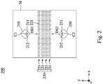
- FIG. 2 is a schematic diagram of a dual polarized antenna according to an embodiment of the present disclosure, in which FIG. 2 is a top view diagram on the x-y plane.
- the dual polarized antenna 200 includes a first antenna unit 210, an isolated band gap 220, and a second antenna unit 230.
- the first antenna unit 210, the isolated band gap 220, and the second antenna unit 230 are all formed on the dielectric board M, and the isolated band gap 220 is disposed between the first antenna unit 210 and the second antenna unit 230 adjacently.
- a minimum distance (for example, the distance DS1 shown in FIG. 2 ) between a center point C1 of the first antenna unit 210 and the isolated band gap 220 is approximately in a range of 0.3 to 0.5 times a wavelength of an operating frequency of the first antenna unit 210,i.e. 3 ⁇ / 10 ⁇ distance DS1 ⁇ ⁇ / 2, in order to achieve a good isolation effect.
- a distance between the center point C1 of the first antenna unit 210 and the isolated band gap 220 is about 0.4 times the wavelength of the operating frequency of the first antenna unit 210, i.e. 2 ⁇ / 5, in order to achieve a better isolation effect.
- a minimum distance (for example, the distance DS2 shown in FIG. 2 ) between the center point C2 of the second antenna unit 230 and the isolated band gap 220 is about in a range of 0.3 to 0.5 times the wavelength of the operating frequency of the second antenna unit 230, i.e. 3 ⁇ / 10 ⁇ distance DS2 ⁇ / 2, in order to achieve a good isolation effect.
- a distance between the center point C2 of the second antenna unit 230 and the isolated band gap 220 is approximately 0.4 times the wavelength of the operating frequency of the second antenna unit 230, i.e. 2 ⁇ / 5, in order to achieve more better isolation effect.
- the first antenna unit 210 and the second antenna unit 230 have the same antenna structure, and are similar to the antenna unit 110 shown in FIG. 1 , and thus the same points are not described herein.
- the first antenna unit 210 and the second antenna unit 230 are symmetrical with the center of the isolated band gap 220 as the axis of symmetry. Therefore, the minimum distance between the center point C1 of the first antenna unit 210 and the isolated band gap 220 is equal to the minimum distance between the center point C2 of the second antenna unit 230 and the isolated band gap 220. In other words, the distance DS1 is the same as the distance DS2.
- a first feed point 211 of the first antenna unit 210 corresponds to the first feed point 231 of the second antenna unit 230
- a second feed point 212 of the first antenna unit 210 corresponds to a second feed point 232 of the second antenna unit 230.
- the isolated band gap 220 includes a plurality of isolated structures 221, and each isolated structure 221 includes a plurality of isolated units 222, and the isolated band gap 220, the isolated structures 221 and the isolated units 222 are respectively similar to the isolated band gap 120, the isolated structure 121, and the isolated units 122 shown in FIG. 1 .
- the isolated band gap includes two pairs of isolated structures 221, i.e. four isolated structures 221. When there are more isolated structures 221, the isolation of the dual polarized antenna 200 is greater. Therefore, with the isolated band gap 220 having two pairs of isolated structures 221, the first antenna unit 210 and the second antenna unit 230 do not affect each other during operation.
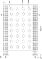
- FIG. 3 is a schematic diagram of a dual polarized antenna according to an embodiment of the present disclosure, in which FIG. 3 is a top view diagram on the x-y plane.
- the dual polarized antenna 300 includes an antenna array 310, a first isolated band gap 320, and a second isolated band gap 330.
- the antenna array 310, the first isolated band gap 320, and the second isolated band gap 330 are all formed on the dielectric board M, and the antenna array 310 is disposed between to the first isolated band gap 320 and the second isolated band gap 330 adjacently.
- the antenna array 310 includes a plurality of antenna units (for example, the antenna units 310a, 310b, 310c, 310d, 310e, and 310f shown in FIG. 3 , which are not individually shown in the figure).
- each antenna unit is similar to the antenna unit shown in FIG. 1 or FIG. 2 , and the same points are not described here.
- a number of antenna units is only for illustration, and is not limited here.
- the antenna array 310 may be divided into at least one first group and at least one second group, and the first group and the second group respectively include a plurality of antenna units.
- the antenna array 310 includes two first groups P1 and two second groups P2, and on the x-y plane, the first groups P1 and the second groups P2 are alternately arranged relative to the Y-axis direction.
- each element or feature in each antenna unit in the first groups P1 is arranged in the same way as the first isolated band gap 320
- each element or feature in each antenna unit in the second groups P2 is arranged in the same way as the first isolated band gap 320.
- the first feed point and the second feed point of the antenna unit in the first group are farther away from the first isolated band gap 320 or the second isolated band gap 330, and the first feed point and the second feed point of the antenna unit in the second group are closer to the first isolated band gap 320 or the second isolated band gap 330.
- the first feed point and the second feed point of the antenna unit in the second group are closer to the first isolated band gap 320 or the second isolated band gap 330.
- the first feed point 311a and the second feed point 312a are disposed adjacent to the first edge 313a and the second edge 314a respectively. Therefore, for this antenna unit 310a, relative to the distance from the first isolated band gap 320, the first feed point 311a and the second feed point 312a are farther away from the first isolated band gap 320.
- the first feeding point 311b and the second feeding point 312b are disposed adjacent to the first edge 313b and the second edge 314b respectively. Therefore, for this antenna unit 310b, relative to the distance from the first isolated band gap 320, the first feed point 311b and the second feed point 312b are closer to the first isolated band gap.
- the distance between any two adjacent antenna units for example, as shown in FIG. 3 , the distance between a center point C of the antenna unit 310c in the first groups P1 and the center point C of the adjacent one antenna unit 310d or the center point C of the antenna unit 310e is the same distance D2.
- a minimum distance (for example, as shown in FIG. 3 , a distance D3 between the center point C of the antenna unit 310f in the second groups P2 and the first isolated band gap 320) between a center point of the antenna unit and the first isolated band gap 320 or the second isolated band gap 330 is approximately in a range of 0.3 to 0.5 times the wavelength of the operating frequency of the antenna unit, i.e. 3 ⁇ / 10 ⁇ distance D3 ⁇ ⁇ / 2, in order to achieve a good isolation effect.
- the minimum distance between the center point of the antenna unit and the first isolated band gap 320 or the second isolated band gap 330 is approximately 0.4 times the wavelength of the operating frequency of the antenna unit, i.e. 2 ⁇ / 5, in order to achieve better isolation effect.
- the first isolated band gap 320 includes a pair of isolated structures 321, i.e. two isolated structures 321, and each isolated structure 321 includes a plurality of isolated units 322.
- the second isolated band gap 330 also includes a pair of isolated structures 331, i.e. two isolated structures 331, and each isolated structure 331 includes a plurality of isolated units 332.
- the first isolated band gap 320 and the second isolated band gap 330 are similar to the isolated band gap shown in FIG. 1 or FIG. 2 , and the same points are not described here.
- the dual polarized antenna 300 of the embodiment further provides or enhances some advantages.
- the dual polarized antenna 300 since the dual polarized antenna 300 includes an antenna array 310 with a plurality of antenna units, the dual polarized antenna 300 has good directivity and a high signal transmission distance. Since the dual polarized antenna 300 includes the first isolated band gap 320 and the second isolated band gap 330, the dual polarized antenna 300 has high isolation.
- FIG. 4 is a schematic diagram of a dual polarized antenna according to an embodiment of the present disclosure, in which FIG. 4 is a top view diagram on the x-y plane.
- the dual polarized antenna 400 includes an antenna array 410, a first isolated band gap 420, and a second isolated band gap 430.
- the antenna array 410, the first isolated band gap 420, and the second isolated band gap 430 are all formed on the dielectric board M, and the antenna array 410 is disposed between the first isolated band gap 420 and the second isolated band gap 430 adjacently.
- the antenna array 410 includes a plurality of antenna units (for example, the antenna units 410a and 410b shown in FIG. 4 are not individually shown in the figure).
- the dual polarized antenna 400 shown in FIG. 4 is similar to the dual polarized antenna 300 shown in FIG. 3 , and the same points are not described here.
- the first isolated band gap 420 includes two pairs of isolated structures 421, i.e. four isolated structures 421, and each isolated structure 421 includes a plurality of isolated units 422.
- the second isolated band gap 430 includes two pairs of isolated structures 431, i.e. four isolated structures 431, and each isolated structure 421 includes a plurality of isolated units 432.
- the first isolated band gap 420 and the second isolated band gap 430 are similar to the isolated band gap shown in one of FIG. 1 , FIG. 2 , or FIG. 3 , and the same points are not described here.
- the dual polarized antenna 400 of this embodiment also has good directivity, high isolation, and long signal transmission distance.
- an operating frequency of 28 GHz is implemented to simulate the application of 5G.
- the dual polarized antenna 300 shown in FIG. 3 the first isolated band gap 320 and the second isolated band gap 330 in FIG. 3 are removed to form a dual polarized antenna (without isolated band gap) of a control group, and achieve a 28 GHz operating frequency with this dual polarized antenna.
- Table 1 uses 28 GHz as the operating frequency and the FtB ratio of the radiation pattern of the dual polarized antenna in the foregoing various embodiments.
- the FtB ratio of the radiation pattern of the control group is relatively lowest.
- the FtB ratio of radiation pattern of a dual polarized antenna for example, the dual polarized antenna 300 of FIG. 3
- an isolated band gap comprising a pair of isolated structures
- a dual polarized antenna for example, the dual polarized antenna 400 in FIG. 4
- an isolated band gap comprising more than two pairs of isolated structures
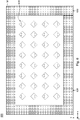
- FIG. 5 is a schematic diagram of a dual polarized antenna according to an embodiment of the present disclosure, in which FIG. 5 is a top view diagram on the x-y plane.
- the dual polarized antenna 500 shown in FIG. 5 is similar to the dual polarized antenna 300 shown in FIG. 3 , and the same points are not described here.
- a second isolated band gap 530 On the x-y plane, a second isolated band gap 530 has an inverted U shape, and forms a closed hollow rectangle with the first isolated band gap 520.
- the antenna array 510 is disposed between the first isolated band gap 520 and the second isolated band gap 530. Or it can be understood that, on the x-y plane, the antenna array 510 is surrounded by the first isolated band gap 520 and the second isolated band gap 530.
- FIG. 6 is a schematic diagram of a dual polarized antenna according to an embodiment of the present disclosure, in which FIG. 6 is a top view diagram on the x-y plane.
- the dual polarized antenna 600 shown in FIG. 6 is similar to the dual polarized antenna 400 shown in FIG. 4 and the dual polarized antenna 500 shown in FIG. 5 , and the same points are not described here.
- the first isolated band gap 620 and the second isolated band gap 630 respectively include two pairs of isolated structures (not shown in FIG. 6 ), i.e. four isolated structures.
- the antenna array 610 is surrounded by the first isolated band gap 620 and the second isolated band gap 630.
- the dual polarized antenna in the embodiments further provides or enhances some advantages.
- the arrangement of the first isolated band gap and the second isolated band gap around the antenna array can further improve the isolation of the dual polarized antenna.
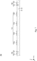
- FIG. 7 is a schematic partial cross-sectional view of a dual polarized antenna 700 according to an embodiment of the present disclosure, in which FIG. 7 is a top view diagram on the x-z plane.
- the dual polarized antenna 700 shown in FIG. 7 is similar to the dual polarized antenna 300 shown in FIG. 3 , the dual polarized antenna 400 shown in FIG. 4 , the dual polarized antenna 500 shown in FIG. 5 and the dual polarized antenna 600 shown in FIG. 6 , and the Y direction of any one shown in FIGS. 3 to 6 is used as a cross-sectional line to draw a partially dual polarized antenna 700 on the x-z plane.
- the dual polarized antenna 700 includes an antenna array 710, a first isolated band gap 720, and a second isolated band gap 730.
- the antenna array 710, the first isolated band gap 720, and the second isolated band gap 730 are all formed on the dielectric board M, and the dielectric board M is disposed on the ground plane G.
- the dielectric constant of the dielectric board M is in a range of 2 to 6.
- the dielectric constant of the dielectric board M is related to the operating wavelength of the dual polarized antenna 700 and a size of each unit in the dual polarized antenna 700 and the relative arrangement therebetween.
- the antenna array 710 is disposed between the first isolated band gap 720 and the second isolated band gap 730 adjacently.
- the antenna array 710 includes a plurality of antenna units 710a, 710b, 710c, and 710d.
- each antenna unit is similar to the antenna unit shown in any one of FIG. 1 to FIG. 6 , and the same points are not described here.
- a number of antenna units is only for illustration, and is not limited here.
- the first isolated band gap 720 includes a plurality of isolated units 722.
- the first isolated band gap 720 is similar to the isolated band gap shown in any one of FIGS. 1 to 6
- the isolated unit 722 is similar to the isolated unit shown in any one of FIGS. 1 to 6 , and the same points are not described here.
- a number of isolated units 722 is only for illustration, and is not limited here.
- the second isolated band gap 730 includes a plurality of isolated units 732.
- the second isolated band gap 730 is similar to the isolated band gap shown in any one of FIGS. 1 to 6
- the isolated unit 732 is similar to the isolated unit shown in any one of FIGS. 1 to 6 , and the same points are not described here.
- a number of isolated units 732 is only for illustration, and is not limited here.
- the isolated unit 722 and the isolated unit 732 have the same structure, and have the same arrangement relative to the antenna array 710 respectively.
- FIG. 8 is a schematic partial cross-sectional view of the isolated unit 722 in the dual polarized antenna according to FIG. 7 , in which FIG. 8 is a top view diagram on the x-z plane.
- the isolated unit 722 includes a top metal sheet 723 and a connection metal via 724. In some embodiments, the isolated unit 722 is mushroom-shaped.
- the top metal sheet 723 is formed on the dielectric board M, and is coupled to the connecting connection metal via 724.
- the top metal sheet 723 is a small square, and is substantially parallel to the ground plane G. In some embodiments, the top metal sheet 723 has a regular three-miniature shape, a circular shape, an oval shape, or a trapezoid shape, and the shape of the top metal sheet 723 is not limited herein.
- connection metal via 724 is formed in the dielectric board M, and is coupled to the ground plane G via the connection metal via 724.
- connection metal via 724 is cylindrical and is substantially perpendicular to the ground plane G and the top metal sheet 723. In some embodiments, the connection metal via 724 is triangular via or square via, and the shape of the connection metal via 724 is not limited herein.
- a length (for example, the length L3 of the side length shown in FIG. 8 ) of the maximum side length of the isolated unit 722 is less than 0.1 times a wavelength of an operating frequency of the dual polarized antenna 700, i.e. ⁇ / 10.
- a distance (for example, the interval distance D1 shown in FIG. 8 ) of the isolated interval between the isolated units 722 is less than 0.02 times the wavelength of the operating frequency of the dual polarized antenna 700, i.e. ⁇ / 50.
- a height (for example, the height H1 shown in FIG. 8 comprising the distance from the top surface of the top metal sheet 723 to the bottom end of the connection metal via 724) of the isolated unit 722 is less than 0.1 times the wavelength of the operating frequency of the dual polarized antenna 700,i.e. ⁇ / 10.
- the dual polarized antenna proposed in the present disclosure can be applied to applications with high isolation and directivity.
- the dual polarized antenna is working, because the included angle between each polarized direction and the isolated band gap is neither 0° nor 90°, signals with different polarized directions will not be blocked by the isolated band gap and thus can be transmitted to another signal processing end.
- the dual polarized antenna can block other noise through the isolated band gap, so the dual polarized antenna has good signal isolation.
Landscapes
- Physics & Mathematics (AREA)
- Optics & Photonics (AREA)
- Variable-Direction Aerials And Aerial Arrays (AREA)
- Waveguide Aerials (AREA)
Abstract
Description
- The present invention relates to the technical field of antennas. More particularly, the present invention relates to a dual polarized antenna with high isolation.
- In recent years, various wireless communication technologies have developed rapidly, and the signal quality and transmission speed are required to be greater. In order to support a wider area network, many wireless communication products include an antenna to receive a signal from another electronic device or to transmit a signal to another electronic device. However, in multi-input multi-output applications of antennas, the antennas have low signal quality due to the low isolation between multiple signals.
- The present disclosure provides a dual polarized antenna comprising a first antenna unit and an isolated band gap. The first antenna unit is formed on the dielectric board, and the first antenna unit being conducted is configured to receive or transmit a signal with each of a first polarized direction and a second polarized direction. The isolated band gap is formed on the dielectric board and disposed adjacent to the first antenna unit. A first included angle which is neither 0° nor 90° is formed between the first polarized direction and the isolated band gap. The dual polarized antenna has good directivity and isolation.
- The present disclosure provides a dual polarized antenna comprising an antenna array and a first isolated band gap. The antenna array is formed on the dielectric board, and the antenna array being conducted is configured to receive or transmit a signal with one of a first polarized direction or a second polarized direction. The first isolated band gap is formed on the dielectric board and disposed adjacent to the antenna array. An included angle which is neither 0° nor 90° is formed between the first polarized direction and the first isolated band gap. The dual polarized antenna has good directivity and isolation.
- It is to be understood that both the foregoing general description and the following detailed description are by examples, and are intended to provide further explanation of the invention as claimed.
- The invention can be more fully understood by reading the following detailed description of the embodiment, with reference made to the accompanying drawings as follows:
-
FIG. 1A is a schematic diagram of a dual polarized antenna according to an embodiment of the present disclosure. -
FIG. 1B is a schematic diagram of an operation of the dual polarized antenna according toFIG. 1A . -
FIG. 2 is a schematic diagram of a dual polarized antenna according to an embodiment of the present disclosure. -
FIG. 3 is a schematic diagram of a dual polarized antenna according to an embodiment of the present disclosure. -
FIG. 4 is a schematic diagram of a dual polarized antenna according to an embodiment of the present disclosure. -
FIG. 5 is a schematic diagram of a dual polarized antenna according to an embodiment of the present disclosure. -
FIG. 6 is a schematic diagram of a dual polarized antenna according to an embodiment of the present disclosure. -
FIG. 7 is a schematic diagram of partial cross-sectional view of a dual polarized antenna according to an embodiment of the present disclosure. -
FIG. 8 is a schematic diagram of partial cross-sectional view of the dual polarized antenna according toFIG. 7 . - Reference will now be made in detail to the present embodiments of the invention, examples of which are illustrated in the accompanying drawings. Wherever possible, the same reference numbers are used in the drawings and the description to refer to the same or like parts.
- In addition, the words "including", "comprising", "having", "containing", etc. used in this article are all open terms, meaning "including but not limited to. In addition, the "and / or" used in this article includes any one or more of the listed items and all combinations thereof.
- In this article, when an element is referred to as "connected" or "coupled", it can be referred to as "electrically connected" or "electrically coupled." "Connected" or "coupled" can also be used to indicate the operation or interaction of two or more components. In addition, although terms such as "first", "second", etc. are used in this document to describe different elements, the terms are only used to distinguish elements or operations described in the same technical terms. Unless the context clearly dictates, the term does not specifically refer to or imply an order or order, nor is it intended to limit the present invention.
- The comparative terms used in this article such as "lower", "bottom", "higher", "top", "left" or "right", etc., are only used to illustrate the implementation mentioned in this article Illustration in the example. In addition to the orientation of directions in the illustration, it also includes other relative orientation terms. For example, if the device is turned over in an illustration, the description between one component and another component may change from "lower" to "higher". Among them, the term "lower" may include two directions, "lower" and "higher", depending only on the orientation of the illustration. Similarly, if the device is turned over in an illustration, the description between one component and another component may change from "lower" or "below" to "upper". Terms such as "lower" or "below" can include two orientations in the up or down direction.
- The terms "roughly", "about", "approximately" and the like described herein are generally expressed within a certain value or within 20% of the average, or preferably within 10%, or better within 5%. If the numerical values described in this article are approximate, it can be inferred that they refer to terms such as "about" and "approximately".
- In various wireless communication products, an antenna is often used to achieve the function of signal transmission. In some applications, in order to increase the transmission distance of a signal, the product further includes a repeater with the antenna to adjust and amplify the signal. In some products, the antenna used in multi-input multi-output is implemented with a dual polarized antenna. Signals transmitted by the antenna may have crosstalk. Therefore, the antenna requires high isolation.
- In some applications, a metal structure which is disposed adjacent to the antenna is configured to generate resonance with the signal of the antenna and to form a structure with high impedance to block the passage of electromagnetic waves with similar frequencies, to achieve the requirements of high isolation. However, the current metal structure and the structure of the antenna or the arrangement therebetween will completely block the signal transmission of the antenna. Especially, when the antenna is a dual polarized antenna, this defect is worse. In view of this, the present disclosure provides the dual polarized antenna with high isolation and directivity that overcomes this drawback.
- In various embodiments of the present disclosure, the dual polarized antenna is constructed in a three-dimensional coordinate system and includes three mutually orthogonal coordinate axes x, y, and z. In some embodiments, the dual polarized antenna is constructed in other types of coordinate systems, and is not limited thereto.
-
FIG. 1A is a schematic diagram of a dual polarizedantenna 100 according to an embodiment of the present disclosure, in whichFIG. 1A is a top view diagram on an x-y plane. - The dual polarized
antenna 100 includes anantenna unit 110 and anisolated band gap 120. Both theantenna unit 110 and theisolated band gap 120 are formed on a dielectric board M, and theantenna unit 110 and theisolated band gap 120 are disposed adjacently. - The
antenna unit 110 is a patch antenna, which includes afirst feed point 111 and asecond feed point 112. Both thefirst feed point 111 and thesecond feed point 112 are coupled to another dielectric board (not shown) parallel to the dielectric board M, and are respectively used to feed signals to receive or transmit a signal with each of a horizontal polarized direction and a vertical polarized direction. - On the x-y plane, the
antenna unit 110 has a parallelogram shape and includes a pair offirst edges 113 having a first length L1 and a pair ofsecond edges 114 having a second length L2. Thefirst feed point 111 is disposed adjacent to one of the first edges 113 (as shown inFIG. 1A ), and thesecond feed point 112 is disposed adjacent to one of the second edges 114 (as shown inFIG. 1A ), in which thesecond edge 114 and thefirst edge 113 are adjacent edges. - In some embodiments, on the x-y plane, the
first feed point 111 is disposed adjacent to the center point (not shown) of thefirst edge 113, and thesecond feed point 112 is disposed adjacent to a center point (not shown) of thesecond edge 114. In some embodiments, a distance (not shown) between a center point of thefirst edge 113 and theisolated band gap 120 and a distance (not shown) between a center point of thesecond edge 114 and theisolated band gap 120 are the same. In some embodiments, a distance (not shown) between thefirst feed point 111 and theisolated band gap 120 and a distance (not shown) between thesecond feed point 112 and theisolated band gap 120 are the same. - In some embodiments, the
antenna unit 110 is square on the x-y plane. In some embodiments, on the x-y plane, theantenna unit 110 is diamond-shaped, and a shape of theantenna unit 110 relative to the x-y plane is not limited herein. - A distance (for example, the distance DS shown in
FIG. 1A ) between a center point C of theantenna unit 110 and theisolated band gap 120 is approximately in a range of 0.3 to 0.5 times a wavelength of an operating frequency of theantenna unit 110, i.e., 3λ / 10 ≦ distance DS ≦ λ / 2, in order to achieve a good isolation effect. In some embodiments, the distance between the center point C of theantenna unit 110 and theisolated band gap 120 is about 0.4 times the wavelength of the operating frequency of theantenna unit 110, i.e. 2λ / 5, in order to achieve better isolation. - The first length L1 of the
first edge 113 and the second length L2 of thesecond edge 114 are both approximately equal to 0.25 times the wavelength of the operating frequency of theantenna unit 110, i.e. λ / 4, in order to achieve good impedance matching and good directivity. In some embodiments, the first length L1 and the second length L2 are equal to each other. - The
isolated band gap 120 includes a plurality ofisolated structures 121. In some embodiments, theisolated band gap 120 is an electromagnetic band gap (EBG) to suppress surface waves on the x-y plane. - On the x-y plane, the
isolated structures 121 are strip metal structures and are arranged adjacent to each other, and theisolated band gap 120 includes a pair of isolated structures. Theisolated structure 121 includes a plurality ofisolated units 122. On the x-y plane, theisolated units 122 are rectangular and arranged adjacent to each other. A number of isolated structures and a number or shape of the isolated units of the various embodiments in the present disclosure are merely illustrative, and are not limited herein. - The
isolated unit 122 includes a top metal sheet (for example, a rectangle of theisolated unit 122 shown inFIG. 1A , not labeled) and a connection metal via (for example, a circle in theisolated unit 122 shown inFIG. 1A , Not shown). The top metal sheet is formed on the dielectric board M, and is coupled to the connection metal via. An end (not shown inFIG. 1A ) of the connection metal via which is not connected to the top metal sheet is coupled to another board parallel to the dielectric board M, and is used to produce electromagnetic induction to form high-impedance characteristics and block the passage of signals with specific frequencies when the top metal sheet receives the signal of a specific frequency (for example, the operating frequency of the antenna unit 110). Therefore, theisolated band gap 120 can block some signals received or transmitted by theantenna unit 110, especially surface signals on the x-y plane, so as to improve the directivity of theantenna unit 110. - A length (for example, the length L3 of the side length shown in
FIG. 1A ) of the maximum side length of theisolated unit 122 is less than 0.1 times the wavelength of the operating frequency of theantenna unit 110, i.e. λ / 10. A distance (for example, the interval distance D1 shown inFIG. 1A ) of the isolated interval between theisolated units 122 is less than 0.02 times the wavelength of the operating frequency of theantenna unit 110, i.e. λ / 50. - In some embodiments, on the x-y plane, the
isolated units 122 are square, and the characteristics of the side lengths of theisolated units 122 and the characteristics of the gap between theisolated units 122 are as described above, and shapes of theisolated units 122 are not limited here. - In some embodiments, the
isolated units 122 corresponds to theisolated unit 722 shown inFIGS. 7 and8 and are described in more detail below. - The relative position of the dual
polarized antenna 100 and the size of each unit can increase the front-to-back ratio (FtB ratio) of the radiation pattern of the signal, and can improve the signal transmission distance and the overall efficiency. In some embodiments, the operating frequency band of the dualpolarized antenna 100 includes the operating frequency (corresponding to a frequency band of millimeter waves) between 27 GHz and 29 GHz, so the dualpolarized antenna 100 can be applied to the fifth generation mobile communication technology (5th generation mobile networks, 5G). - Reference is made to
FIG. 1B. FIG. 1B is a schematic diagram of the operation of the dual polarized antenna ofFIG. 1A according to some embodiments of the present disclosure. For the sake of brevity of illustration and the convenience of understanding of present disclosure, some units, which are the same as those inFIG. 1A , are not shown inFIG. 1B . - When the dual
polarized antenna 100 operates, the signal is transmitted in the Z direction, and the signal with each of a horizontal polarized direction and a vertical polarized direction are simultaneously received or transmitted by theantenna unit 110. As shown inFIG. 1B , the signal S1 with the horizontal polarized direction is received or transmitted by the first feed point 111 (as show inFIG. 1A ), and the signal S2 with the vertical polarized direction is also received or transmitted by the second feed point 112 (as shown inFIG. 1A ). - A first included angle θ1 is formed between the horizontal polarized direction (for example, the electric field direction Ê of the signal S1 shown in
FIG. 1B ) and theisolated band gap 120, and a second included angle θ2 is formed between the vertical polarized direction (for example, the electric field direction Ê of the signal S2 shown inFIG. 1B ) and the isolated band gap. A size of the first included angle θ1 and a size of the second included angle θ2 are neither 0° nor 90°. In this embodiment, it can also be understood that the horizontal polarized direction takes the positive x-axis (+x) as the reference axis and has a first included angle θ1 with the positive x-axis. The vertical polarized direction is based on the negative x-axis (-x) and has a second included angle θ2 with the negative x-axis. - In some embodiments, the size of the first included angle θ1 is in a range of 40 ° to 50 °. In some embodiments, the size of the first included angle θ1 is equal to the size of the second included angle θ2. In some embodiments, the first included angle θ1 and the second included angle θ2 are complementary angles.
- In this way, the dual
polarized antenna 100 can simultaneously transmit two signals (for example, the signals S1 and S2 shown inFIG. 1B ) with both of different polarized directions, and these signals will not be blocked by theisolated band gap 120 to facilitate the signals to transmit to other signal processing ends. At the same time, the electromagnetic isolation of theisolated band gap 120 can block other noises, thereby increasing the isolation between the dualpolarized antenna 100 and other communication units. -
FIG. 2 is a schematic diagram of a dual polarized antenna according to an embodiment of the present disclosure, in whichFIG. 2 is a top view diagram on the x-y plane. - The dual
polarized antenna 200 includes afirst antenna unit 210, anisolated band gap 220, and asecond antenna unit 230. Thefirst antenna unit 210, theisolated band gap 220, and thesecond antenna unit 230 are all formed on the dielectric board M, and theisolated band gap 220 is disposed between thefirst antenna unit 210 and thesecond antenna unit 230 adjacently. - On the x-y plane, a minimum distance (for example, the distance DS1 shown in
FIG. 2 ) between a center point C1 of thefirst antenna unit 210 and theisolated band gap 220 is approximately in a range of 0.3 to 0.5 times a wavelength of an operating frequency of thefirst antenna unit 210,i.e. 3λ / 10 ≦ distance DS1 ≦ λ / 2, in order to achieve a good isolation effect. In some embodiments, a distance between the center point C1 of thefirst antenna unit 210 and theisolated band gap 220 is about 0.4 times the wavelength of the operating frequency of thefirst antenna unit 210, i.e. 2λ / 5, in order to achieve a better isolation effect. - Similarly, a minimum distance (for example, the distance DS2 shown in
FIG. 2 ) between the center point C2 of thesecond antenna unit 230 and theisolated band gap 220 is about in a range of 0.3 to 0.5 times the wavelength of the operating frequency of thesecond antenna unit 230, i.e. 3λ / 10 ≦ distance DS2 ≦λ / 2, in order to achieve a good isolation effect. In some embodiments, a distance between the center point C2 of thesecond antenna unit 230 and theisolated band gap 220 is approximately 0.4 times the wavelength of the operating frequency of thesecond antenna unit 230, i.e. 2λ / 5, in order to achieve more better isolation effect. - In some embodiments, the
first antenna unit 210 and thesecond antenna unit 230 have the same antenna structure, and are similar to theantenna unit 110 shown inFIG. 1 , and thus the same points are not described herein. - In some embodiments, the
first antenna unit 210 and thesecond antenna unit 230 are symmetrical with the center of theisolated band gap 220 as the axis of symmetry. Therefore, the minimum distance between the center point C1 of thefirst antenna unit 210 and theisolated band gap 220 is equal to the minimum distance between the center point C2 of thesecond antenna unit 230 and theisolated band gap 220. In other words, the distance DS1 is the same as the distance DS2. In addition, afirst feed point 211 of thefirst antenna unit 210 corresponds to thefirst feed point 231 of thesecond antenna unit 230, and asecond feed point 212 of thefirst antenna unit 210 corresponds to asecond feed point 232 of thesecond antenna unit 230. - The
isolated band gap 220 includes a plurality ofisolated structures 221, and eachisolated structure 221 includes a plurality ofisolated units 222, and theisolated band gap 220, theisolated structures 221 and theisolated units 222 are respectively similar to theisolated band gap 120, theisolated structure 121, and theisolated units 122 shown inFIG. 1 . - The isolated band gap includes two pairs of
isolated structures 221, i.e. fourisolated structures 221. When there are moreisolated structures 221, the isolation of the dualpolarized antenna 200 is greater. Therefore, with theisolated band gap 220 having two pairs ofisolated structures 221, thefirst antenna unit 210 and thesecond antenna unit 230 do not affect each other during operation. -
FIG. 3 is a schematic diagram of a dual polarized antenna according to an embodiment of the present disclosure, in whichFIG. 3 is a top view diagram on the x-y plane. - The dual
polarized antenna 300 includes anantenna array 310, a firstisolated band gap 320, and a secondisolated band gap 330. Theantenna array 310, the firstisolated band gap 320, and the secondisolated band gap 330 are all formed on the dielectric board M, and theantenna array 310 is disposed between to the firstisolated band gap 320 and the secondisolated band gap 330 adjacently. - The
antenna array 310 includes a plurality of antenna units (for example, theantenna units FIG. 3 , which are not individually shown in the figure). In some embodiments, each antenna unit is similar to the antenna unit shown inFIG. 1 orFIG. 2 , and the same points are not described here. A number of antenna units is only for illustration, and is not limited here. - In some embodiments, the
antenna array 310 may be divided into at least one first group and at least one second group, and the first group and the second group respectively include a plurality of antenna units. For example, inFIG. 3 , theantenna array 310 includes two first groups P1 and two second groups P2, and on the x-y plane, the first groups P1 and the second groups P2 are alternately arranged relative to the Y-axis direction. In addition, each element or feature in each antenna unit in the first groups P1 is arranged in the same way as the firstisolated band gap 320, and each element or feature in each antenna unit in the second groups P2 is arranged in the same way as the firstisolated band gap 320. - In some embodiments, on the x-y plane, with the first
isolated band gap 320 or the secondisolated band gap 330 as the reference, for the position of the feed point in each antenna unit relative to this antenna unit, the first feed point and the second feed point of the antenna unit in the first group are farther away from the firstisolated band gap 320 or the secondisolated band gap 330, and the first feed point and the second feed point of the antenna unit in the second group are closer to the firstisolated band gap 320 or the secondisolated band gap 330. For example, inFIG. 3 , on the x-y plane, with the firstisolated band gap 320 as the reference, for theantenna unit 310a in the first groups P1, the first feed point 311a and thesecond feed point 312a are disposed adjacent to thefirst edge 313a and thesecond edge 314a respectively. Therefore, for thisantenna unit 310a, relative to the distance from the firstisolated band gap 320, the first feed point 311a and thesecond feed point 312a are farther away from the firstisolated band gap 320. Similarly, for theantenna unit 310b in the second groups P2, thefirst feeding point 311b and thesecond feeding point 312b are disposed adjacent to thefirst edge 313b and thesecond edge 314b respectively. Therefore, for thisantenna unit 310b, relative to the distance from the firstisolated band gap 320, thefirst feed point 311b and thesecond feed point 312b are closer to the first isolated band gap. - On the x-y plane, the distance between any two adjacent antenna units, for example, as shown in
FIG. 3 , the distance between a center point C of theantenna unit 310c in the first groups P1 and the center point C of the adjacent oneantenna unit 310d or the center point C of theantenna unit 310e is the same distance D2. - On the x-y plane, a minimum distance (for example, as shown in
FIG. 3 , a distance D3 between the center point C of theantenna unit 310f in the second groups P2 and the first isolated band gap 320) between a center point of the antenna unit and the firstisolated band gap 320 or the secondisolated band gap 330 is approximately in a range of 0.3 to 0.5 times the wavelength of the operating frequency of the antenna unit, i.e. 3λ / 10 ≦ distance D3 ≦ λ / 2, in order to achieve a good isolation effect. In some embodiments, the minimum distance between the center point of the antenna unit and the firstisolated band gap 320 or the secondisolated band gap 330 is approximately 0.4 times the wavelength of the operating frequency of the antenna unit, i.e. 2λ / 5, in order to achieve better isolation effect. - The first
isolated band gap 320 includes a pair ofisolated structures 321, i.e. twoisolated structures 321, and eachisolated structure 321 includes a plurality ofisolated units 322. The secondisolated band gap 330 also includes a pair ofisolated structures 331, i.e. twoisolated structures 331, and eachisolated structure 331 includes a plurality ofisolated units 332. The firstisolated band gap 320 and the secondisolated band gap 330 are similar to the isolated band gap shown inFIG. 1 orFIG. 2 , and the same points are not described here. - In the embodiment shown in
FIG. 3 , in addition to the effect of the dual polarized antenna in the foregoing embodiment, the dualpolarized antenna 300 of the embodiment further provides or enhances some advantages. For example, since the dualpolarized antenna 300 includes anantenna array 310 with a plurality of antenna units, the dualpolarized antenna 300 has good directivity and a high signal transmission distance. Since the dualpolarized antenna 300 includes the firstisolated band gap 320 and the secondisolated band gap 330, the dualpolarized antenna 300 has high isolation. -
FIG. 4 is a schematic diagram of a dual polarized antenna according to an embodiment of the present disclosure, in whichFIG. 4 is a top view diagram on the x-y plane. - The dual
polarized antenna 400 includes anantenna array 410, a firstisolated band gap 420, and a secondisolated band gap 430. Theantenna array 410, the firstisolated band gap 420, and the secondisolated band gap 430 are all formed on the dielectric board M, and theantenna array 410 is disposed between the firstisolated band gap 420 and the secondisolated band gap 430 adjacently. Theantenna array 410 includes a plurality of antenna units (for example, theantenna units FIG. 4 are not individually shown in the figure). The dualpolarized antenna 400 shown inFIG. 4 is similar to the dualpolarized antenna 300 shown inFIG. 3 , and the same points are not described here. - The first
isolated band gap 420 includes two pairs ofisolated structures 421, i.e. fourisolated structures 421, and eachisolated structure 421 includes a plurality ofisolated units 422. The secondisolated band gap 430 includes two pairs ofisolated structures 431, i.e. fourisolated structures 431, and eachisolated structure 421 includes a plurality ofisolated units 432. The firstisolated band gap 420 and the secondisolated band gap 430 are similar to the isolated band gap shown in one ofFIG. 1 ,FIG. 2 , orFIG. 3 , and the same points are not described here. - In the embodiment shown in
FIG. 4 , the dualpolarized antenna 400 of this embodiment also has good directivity, high isolation, and long signal transmission distance. - In some embodiments, according to the dual
polarized antennas FIGS. 3 and4 , an operating frequency of 28 GHz is implemented to simulate the application of 5G. At the same time, according to the dualpolarized antenna 300 shown inFIG. 3 , the firstisolated band gap 320 and the secondisolated band gap 330 inFIG. 3 are removed to form a dual polarized antenna (without isolated band gap) of a control group, and achieve a 28 GHz operating frequency with this dual polarized antenna. Table 1 uses 28 GHz as the operating frequency and the FtB ratio of the radiation pattern of the dual polarized antenna in the foregoing various embodiments.Table 1 dual polarized antenna front-to-back ratio (dB) control group (without isolated band gap) 24 FIG. 3 (with a pair of isolated structures)27.1 FIG. 4 (with two pairs of isolated structures)43.6 - As shown in Table 1, the FtB ratio of the radiation pattern of the control group is relatively lowest. The FtB ratio of radiation pattern of a dual polarized antenna (for example, the dual
polarized antenna 300 ofFIG. 3 ) with an isolated band gap comprising a pair of isolated structures or a dual polarized antenna (for example, the dualpolarized antenna 400 inFIG. 4 ) with an isolated band gap comprising more than two pairs of isolated structures is greater than the FtB ratio of radiation pattern of the control group. Therefore, the dual polarized antenna proposed in the present disclosure can be applied to 5G technology and is an application with high isolation and directivity. -
FIG. 5 is a schematic diagram of a dual polarized antenna according to an embodiment of the present disclosure, in whichFIG. 5 is a top view diagram on the x-y plane. The dualpolarized antenna 500 shown inFIG. 5 is similar to the dualpolarized antenna 300 shown inFIG. 3 , and the same points are not described here. - On the x-y plane, a second
isolated band gap 530 has an inverted U shape, and forms a closed hollow rectangle with the firstisolated band gap 520. Theantenna array 510 is disposed between the firstisolated band gap 520 and the secondisolated band gap 530. Or it can be understood that, on the x-y plane, theantenna array 510 is surrounded by the firstisolated band gap 520 and the secondisolated band gap 530. -
FIG. 6 is a schematic diagram of a dual polarized antenna according to an embodiment of the present disclosure, in whichFIG. 6 is a top view diagram on the x-y plane. The dualpolarized antenna 600 shown inFIG. 6 is similar to the dualpolarized antenna 400 shown inFIG. 4 and the dualpolarized antenna 500 shown inFIG. 5 , and the same points are not described here. - The first
isolated band gap 620 and the secondisolated band gap 630 respectively include two pairs of isolated structures (not shown inFIG. 6 ), i.e. four isolated structures. On the x-y plane, theantenna array 610 is surrounded by the firstisolated band gap 620 and the secondisolated band gap 630. - In the embodiment shown in
FIG. 5 orFIG. 6 , in addition to the effects of the dual polarized antenna in the foregoing embodiments, the dual polarized antenna in the embodiments further provides or enhances some advantages. For example, the arrangement of the first isolated band gap and the second isolated band gap around the antenna array can further improve the isolation of the dual polarized antenna. -
FIG. 7 is a schematic partial cross-sectional view of a dualpolarized antenna 700 according to an embodiment of the present disclosure, in whichFIG. 7 is a top view diagram on the x-z plane. The dualpolarized antenna 700 shown inFIG. 7 is similar to the dualpolarized antenna 300 shown inFIG. 3 , the dualpolarized antenna 400 shown inFIG. 4 , the dualpolarized antenna 500 shown inFIG. 5 and the dualpolarized antenna 600 shown inFIG. 6 , and the Y direction of any one shown inFIGS. 3 to 6 is used as a cross-sectional line to draw a partially dualpolarized antenna 700 on the x-z plane. - The dual
polarized antenna 700 includes anantenna array 710, a firstisolated band gap 720, and a secondisolated band gap 730. Theantenna array 710, the firstisolated band gap 720, and the secondisolated band gap 730 are all formed on the dielectric board M, and the dielectric board M is disposed on the ground plane G. - In some embodiments, the dielectric constant of the dielectric board M is in a range of 2 to 6. The dielectric constant of the dielectric board M is related to the operating wavelength of the dual
polarized antenna 700 and a size of each unit in the dualpolarized antenna 700 and the relative arrangement therebetween. - The
antenna array 710 is disposed between the firstisolated band gap 720 and the secondisolated band gap 730 adjacently. Theantenna array 710 includes a plurality ofantenna units FIG. 1 to FIG. 6 , and the same points are not described here. A number of antenna units is only for illustration, and is not limited here. - The first
isolated band gap 720 includes a plurality ofisolated units 722. The firstisolated band gap 720 is similar to the isolated band gap shown in any one ofFIGS. 1 to 6 , and theisolated unit 722 is similar to the isolated unit shown in any one ofFIGS. 1 to 6 , and the same points are not described here. A number ofisolated units 722 is only for illustration, and is not limited here. - The second
isolated band gap 730 includes a plurality ofisolated units 732. The secondisolated band gap 730 is similar to the isolated band gap shown in any one ofFIGS. 1 to 6 , and theisolated unit 732 is similar to the isolated unit shown in any one ofFIGS. 1 to 6 , and the same points are not described here. A number ofisolated units 732 is only for illustration, and is not limited here. - In some embodiments, the
isolated unit 722 and theisolated unit 732 have the same structure, and have the same arrangement relative to theantenna array 710 respectively. -
FIG. 8 is a schematic partial cross-sectional view of theisolated unit 722 in the dual polarized antenna according toFIG. 7 , in whichFIG. 8 is a top view diagram on the x-z plane. - The
isolated unit 722 includes atop metal sheet 723 and a connection metal via 724. In some embodiments, theisolated unit 722 is mushroom-shaped. - The
top metal sheet 723 is formed on the dielectric board M, and is coupled to the connecting connection metal via 724. - In some embodiments, the
top metal sheet 723 is a small square, and is substantially parallel to the ground plane G. In some embodiments, thetop metal sheet 723 has a regular three-miniature shape, a circular shape, an oval shape, or a trapezoid shape, and the shape of thetop metal sheet 723 is not limited herein. - The connection metal via 724 is formed in the dielectric board M, and is coupled to the ground plane G via the connection metal via 724.
- In some embodiments, the connection metal via 724 is cylindrical and is substantially perpendicular to the ground plane G and the
top metal sheet 723. In some embodiments, the connection metal via 724 is triangular via or square via, and the shape of the connection metal via 724 is not limited herein. - A length (for example, the length L3 of the side length shown in
FIG. 8 ) of the maximum side length of theisolated unit 722 is less than 0.1 times a wavelength of an operating frequency of the dualpolarized antenna 700, i.e. λ / 10. A distance (for example, the interval distance D1 shown inFIG. 8 ) of the isolated interval between theisolated units 722 is less than 0.02 times the wavelength of the operating frequency of the dualpolarized antenna 700, i.e. λ / 50. A height (for example, the height H1 shown inFIG. 8 comprising the distance from the top surface of thetop metal sheet 723 to the bottom end of the connection metal via 724) of theisolated unit 722 is less than 0.1 times the wavelength of the operating frequency of the dualpolarized antenna 700,i.e. λ / 10. - In summary, the dual polarized antenna proposed in the present disclosure can be applied to applications with high isolation and directivity. When the dual polarized antenna is working, because the included angle between each polarized direction and the isolated band gap is neither 0° nor 90°, signals with different polarized directions will not be blocked by the isolated band gap and thus can be transmitted to another signal processing end. At the same time, the dual polarized antenna can block other noise through the isolated band gap, so the dual polarized antenna has good signal isolation.
Claims (15)
- A dual polarized antenna (100 and 200), characterized by comprising:a first antenna unit (110 and 210) formed on a dielectric board (M), wherein the first antenna unit (110 and 210) being conducted is configured to receive or transmit a signal (S1 and S2) with each of a first polarized direction and a second polarized direction; andan isolated band gap (120 and 220) formed on the dielectric board (M) and disposed adjacent to the first antenna unit (110 and 210),wherein a first included angle (θ1) which is neither 0° nor 90° is formed between the first polarized direction and the isolated band gap (120 and 220).
- The dual polarized antenna (100 and 200) of claim 1, wherein a second included angle (θ2) which is neither 0° nor 90° is formed between the second polarized direction and the isolated band gap (120 and 220).
- The dual polarized antenna (100 and 200) of one of claims 1 to 2, wherein the first antenna unit (110 and 210) comprises:a first feed point (111 and 211) configured to receive or transmit the signal (S1) with the first polarized direction; anda second feed point (112 and 212) configured to receive or transmit the signal (S2) with the second polarized direction,wherein the first feed point (111 and 211) is disposed adjacent to a first edge (113) of the first antenna unit (110 and 210),the second feed point (112 and 212) is disposed adjacent to a second edge (114) of the first antenna unit (110 and 210) which is adjacent to the first edge (113), anda center point of the first edge (113) and a center point of the second edge (114) are respectively equidistant from the isolated band gap (120 and 220),wherein lengths of the first edge (113) and the second edge (114) are respectively approximately equal to 0.25 times a wavelength of an operating frequency of the first antenna unit (110 and 210).
- The dual polarized antenna (100 and 200) of one of claims 1 to 3, wherein a distance between a center point of the first antenna unit (110 and 210) and the isolated band gap (120 and 220) is in a range of 0.3 to 0.5 times a wavelength of an operating frequency of the first antenna unit (110 and 210).
- The dual polarized antenna (100 and 200) of one of claims 1 to 4, wherein the isolated band gap (120 and 220) comprises:a plurality of isolated structures (121 and 221), wherein the plurality of isolated structures (121 and 221) are adjacent to each other,wherein each of the plurality of isolated structures (121 and 221) is a strip metal structure, and a number of the plurality of isolated structures (121 and 221) is an even number,wherein each of the plurality of isolated structures (121 and 221) comprises:
a plurality of isolated units (122 and 222), wherein the plurality of isolated units (122 and 222) are disposed adjacent to each other, and an isolated interval between adjacent two of the plurality of isolated units (122 and 222) is less than 0.02 times a wavelength of an operating frequency of the first antenna unit (110 and 210). - The dual polarized antenna (100 and 200) of claim 5, wherein a maximum side length or a height of each of the plurality of isolated units (122 and 222) is less than 0.1 times the wavelength of the operating frequency of the first antenna unit (110 and 210).
- The dual polarized antenna (100 and 200) of claim 5, wherein each of the plurality of isolated units (122 and 222) comprises:a connection metal via (724); anda top metal sheet (723) coupled to a ground plane (G) via the connection metal via (724).
- The dual polarized antenna (100 and 200) of one of claims 1 to 7, further comprising:a second antenna unit (230), formed on the dielectric board (M), and the second antenna unit (230) being conducted is configured to receive or transmit a signal (S1 and S2) with each of the first polarized direction and the second polarized direction,wherein the isolated band gap (120 and 220) is disposed between the first antenna unit (110 and 210) and the second antenna unit (230), and the first antenna unit (110 and 210) and the second antenna unit (230) are symmetrical with the isolated band gap (120 and 220) as an axis of symmetry.
- The dual polarized antenna(100 and 200) of one of claims 1 to 8, wherein the first included angle (θ1) is in a range of 40° to 50°.
- A dual polarized antenna (300, 400, 500, 600 and 700), characterized by comprising:an antenna array (310, 410, 510, 610 and 710) formed on a dielectric board (M), and the antenna array (310, 410, 510, 610 and 710) being conducted is configured to receive or transmit a signal (S1 and S2) with one of a first polarized direction or a second polarized direction; anda first isolated band gap (320, 420, 520, 620 and 720) formed on the dielectric board (M) and disposed adjacent to the antenna array (310, 410, 510, 610 and 710),wherein an included angle which is neither 0° nor 90° is formed between the first polarized direction and the first isolated band gap (320, 420, 520, 620 and 720).
- The dual polarized antenna (300, 400, 500, 600 and 700) of claim 10, wherein the antenna array (310, 410, 510, 610 and 710) comprises a plurality of antenna units (310a, 310b, 310c, 310d, 310f, 410a, 410b, 710a, 710b, 710c and 710d), and each of the plurality of antenna units (310a, 310b, 310c, 310d, 310f, 410a, 410b, 710a, 710b, 710c and 710d) comprises:a first feed point (311a and 311b) configured to receive or transmit the signal with the first polarized direction; anda second feed point (312a and 312b) configured to receive or transmit the signal with the second polarized direction,a second isolated band gap (330, 430, 530, 630 and 730) formed on the dielectric board (M) and disposed outside the antenna array (310, 410, 510, 610 and 710),wherein the second polarized direction is orthogonal to the first polarized direction, and the included angle is formed between the second polarized direction and the first isolated band gap (320, 420, 520, 620 and 720),the antenna array (310, 410, 510, 610 and 710) is disposed between the first isolated band gap (320, 420, 520, 620 and 720) and the second isolated band gap (330, 430, 530, 630 and 730),the first feed point (311a and 311b) is disposed adjacent to a first edge (313a and 313b) of each of the plurality of antenna units (310a, 310b, 310c, 310d, 310f, 410a, 410b, 710a, 710b, 710c and 710d),the second feed point (312a and 312b) is disposed adjacent to a second edge (314a and 314b) of each of the plurality of antenna units (310a, 310b, 310c, 310d, 310f, 410a, 410b, 710a, 710b, 710c and 710d) which is adjacent to the first edge (313a and 313b), anda center point of the first edge (313a and 313b) and a center point of the second edge (314a and 314b) are respectively equidistant from the first isolated band gap (320, 420, 520, 620 and 720).
- The dual polarized antenna (300, 400, 500, 600 and 700) of claim 11, wherein, for each of the plurality of antenna units (310a, 310b, 310c, 310d, 310f, 410a, 410b, 710a, 710b, 710c and 710d), relative to a distance from the first isolated band gap (320, 420, 520, 620 and 720),
the first feed point (311 a and 311b) and the second feed point (312a and 312b) of each of the plurality of antenna units (310a, 310b, 310c, 310d, 310f, 410a, 410b, 710a, 710b, 710c and 710d) of at least one first group (P1) are farther away from the first isolated band gap (320, 420, 520, 620 and 720), and
the first feed point (311a and 311b) and the second feed point (312a and 312b) of each of the plurality of antenna units (310a, 310b, 310c, 310d, 310f, 410a, 410b, 710a, 710b, 710c and 710d) of at least one second group (P2) are closer to the first isolated band gap (320, 420, 520, 620 and 720). - The dual polarized antenna of claim 11, wherein lengths of the first edge (313a and 313b) and the second edge (314a and 314b) are each approximately equal to 0.25 times a wavelength of an operating frequency of the antenna units (310a, 310b, 310c, 310d, 310f, 410a, 410b, 710a, 710b, 710c and 710d).
- The dual polarized antenna (300, 400, 500, 600 and 700) of claim 11, wherein a minimum distance between center points of the antenna units (310a, 310b, 310c, 310d, 310f, 410a, 410b, 710a, 710b, 710c and 710d) and the first isolated band gap (320, 420, 520, 620 and 720) is in a range of 0.3 to 0.5 times a wavelength of an operating frequency of the antenna units (310a, 310b, 310c, 310d, 310f, 410a, 410b, 710a, 710b, 710c and 710d).
- The dual polarized antenna (300, 400, 500, 600 and 700) of claim 11, wherein an interval between adjacent two of the plurality of antenna units (310a, 310b, 310c, 310d, 310f, 410a, 410b, 710a, 710b, 710c and 710d) is approximately equal to 0.5 times a wavelength of an operating frequency of the antenna units (310a, 310b, 310c, 310d, 310f, 410a, 410b, 710a, 710b, 710c and 710d).
Applications Claiming Priority (2)
| Application Number | Priority Date | Filing Date | Title |
|---|---|---|---|
| CN201910671907.3A CN112290234A (en) | 2019-07-24 | 2019-07-24 | communication device |
| CN202010086565.1A CN112310617B (en) | 2019-07-24 | 2020-02-11 | Dual polarized antenna |
Publications (3)
| Publication Number | Publication Date |
|---|---|
| EP3771038A1 true EP3771038A1 (en) | 2021-01-27 |
| EP3771038C0 EP3771038C0 (en) | 2025-11-12 |
| EP3771038B1 EP3771038B1 (en) | 2025-11-12 |
Family
ID=71527733
Family Applications (1)
| Application Number | Title | Priority Date | Filing Date |
|---|---|---|---|
| EP20186251.3A Active EP3771038B1 (en) | 2019-07-24 | 2020-07-16 | Dual polarized antenna |
Country Status (2)
| Country | Link |
|---|---|
| EP (1) | EP3771038B1 (en) |
| ES (1) | ES3058600T3 (en) |
Cited By (2)
| Publication number | Priority date | Publication date | Assignee | Title |
|---|---|---|---|---|
| CN113964487A (en) * | 2021-03-24 | 2022-01-21 | 友达光电股份有限公司 | Antenna device |
| WO2024174228A1 (en) * | 2023-02-24 | 2024-08-29 | 北京京东方传感技术有限公司 | Antenna, linear array, and antenna array |
Citations (6)
| Publication number | Priority date | Publication date | Assignee | Title |
|---|---|---|---|---|
| US20030011522A1 (en) * | 2001-06-15 | 2003-01-16 | Mckinzie William E. | Aperture antenna having a high-impedance backing |
| US20140049437A1 (en) * | 2012-08-17 | 2014-02-20 | Mediatek Inc. | Multi-input multi-output antenna with electromagnetic band-gap structure |
| CN104157982A (en) * | 2014-07-07 | 2014-11-19 | 华东交通大学 | Dual-polarized MIMO antenna based on EBG structure |
| US20160028161A1 (en) * | 2013-03-13 | 2016-01-28 | Denso Corporation | Antenna apparatus having patch antenna |
| DE112017001941T5 (en) * | 2016-04-06 | 2019-01-10 | Denso Corporation | antenna apparatus |
| CN109904605A (en) * | 2019-03-05 | 2019-06-18 | 电子科技大学 | Wideband Polarization Reconfigurable Antenna and High Performance Antenna Array Based on Hybrid HIS |
Family Cites Families (5)
| Publication number | Priority date | Publication date | Assignee | Title |
|---|---|---|---|---|
| JPH09284031A (en) * | 1996-04-15 | 1997-10-31 | Nec Corp | Microstrip antenna |
| NL1019022C2 (en) * | 2001-09-24 | 2003-03-25 | Thales Nederland Bv | Printed antenna powered by a patch. |
| US7019709B2 (en) * | 2002-08-22 | 2006-03-28 | Matsushita Electric Industrial Co., Ltd. | Antenna device |
| CN2783546Y (en) * | 2005-02-01 | 2006-05-24 | 烟台高盈科技有限公司 | 3G 30 degree dual polarized plate shape antenna for base station |
| CN108767449B (en) * | 2018-06-15 | 2020-12-15 | 京信通信技术(广州)有限公司 | Multi-system fusion antenna based on AMC structure |
-
2020
- 2020-07-16 EP EP20186251.3A patent/EP3771038B1/en active Active
- 2020-07-16 ES ES20186251T patent/ES3058600T3/en active Active
Patent Citations (6)
| Publication number | Priority date | Publication date | Assignee | Title |
|---|---|---|---|---|
| US20030011522A1 (en) * | 2001-06-15 | 2003-01-16 | Mckinzie William E. | Aperture antenna having a high-impedance backing |
| US20140049437A1 (en) * | 2012-08-17 | 2014-02-20 | Mediatek Inc. | Multi-input multi-output antenna with electromagnetic band-gap structure |
| US20160028161A1 (en) * | 2013-03-13 | 2016-01-28 | Denso Corporation | Antenna apparatus having patch antenna |
| CN104157982A (en) * | 2014-07-07 | 2014-11-19 | 华东交通大学 | Dual-polarized MIMO antenna based on EBG structure |
| DE112017001941T5 (en) * | 2016-04-06 | 2019-01-10 | Denso Corporation | antenna apparatus |
| CN109904605A (en) * | 2019-03-05 | 2019-06-18 | 电子科技大学 | Wideband Polarization Reconfigurable Antenna and High Performance Antenna Array Based on Hybrid HIS |
Cited By (2)
| Publication number | Priority date | Publication date | Assignee | Title |
|---|---|---|---|---|
| CN113964487A (en) * | 2021-03-24 | 2022-01-21 | 友达光电股份有限公司 | Antenna device |
| WO2024174228A1 (en) * | 2023-02-24 | 2024-08-29 | 北京京东方传感技术有限公司 | Antenna, linear array, and antenna array |
Also Published As
| Publication number | Publication date |
|---|---|
| ES3058600T3 (en) | 2026-03-11 |
| EP3771038C0 (en) | 2025-11-12 |
| EP3771038B1 (en) | 2025-11-12 |
Similar Documents
| Publication | Publication Date | Title |
|---|---|---|
| JP6984107B2 (en) | Dual polarized antenna | |
| US11316283B2 (en) | Dual polarized antenna | |
| US12040544B2 (en) | Common aperture antenna and communication device | |
| US20200091599A1 (en) | Antenna device | |
| US9985355B2 (en) | Antenna module | |
| CN112310617B (en) | Dual polarized antenna | |
| EP3771038B1 (en) | Dual polarized antenna | |
| EP3852194A1 (en) | Terminal device antenna | |
| EP3297094B1 (en) | Device for wireless access | |
| CN114597639A (en) | A broadband low-frequency filter oscillator and multi-frequency base station antenna | |
| US10270173B2 (en) | Patch antenna | |
| US20210126358A1 (en) | Dual polarized antenna and antenna array | |
| US20200212555A1 (en) | Double-frequency antenna structure with high isolation | |
| US10707583B2 (en) | Wireless communication module | |
| CN114256622A (en) | Novel millimeter wave array plane coupling annular decoupling structure and antenna array | |
| CN220291071U (en) | Multi-feed point distributed communication antenna | |
| US10361475B2 (en) | Antenna unit and antenna system | |
| CN112490667A (en) | High-isolation symmetrical folding short-circuit dipole two-unit MIMO antenna | |
| CN217134687U (en) | Dual-polarization radiating element, antenna and antenna system | |
| TW202316735A (en) | Antenna element and antenna | |
| CN116435767A (en) | A low-frequency wave-transparent radiation unit and a multi-frequency common-aperture antenna using it | |
| CN114361780A (en) | Broadband radiating element and base station antenna | |
| CN208637592U (en) | Archimedian screw array antenna | |
| CN210379412U (en) | Antenna, antenna assembly and electronic equipment | |
| CN118763413B (en) | A dual-polarized filter antenna |
Legal Events
| Date | Code | Title | Description |
|---|---|---|---|
| PUAI | Public reference made under article 153(3) epc to a published international application that has entered the european phase |
Free format text: ORIGINAL CODE: 0009012 |
|
| STAA | Information on the status of an ep patent application or granted ep patent |
Free format text: STATUS: THE APPLICATION HAS BEEN PUBLISHED |
|
| AK | Designated contracting states |
Kind code of ref document: A1 Designated state(s): AL AT BE BG CH CY CZ DE DK EE ES FI FR GB GR HR HU IE IS IT LI LT LU LV MC MK MT NL NO PL PT RO RS SE SI SK SM TR |
|
| AX | Request for extension of the european patent |
Extension state: BA ME |
|
| STAA | Information on the status of an ep patent application or granted ep patent |
Free format text: STATUS: REQUEST FOR EXAMINATION WAS MADE |
|
| 17P | Request for examination filed |
Effective date: 20210708 |
|
| RBV | Designated contracting states (corrected) |
Designated state(s): AL AT BE BG CH CY CZ DE DK EE ES FI FR GB GR HR HU IE IS IT LI LT LU LV MC MK MT NL NO PL PT RO RS SE SI SK SM TR |
|
| STAA | Information on the status of an ep patent application or granted ep patent |
Free format text: STATUS: EXAMINATION IS IN PROGRESS |
|
| 17Q | First examination report despatched |
Effective date: 20231129 |
|
| REG | Reference to a national code |
Ref country code: DE Ipc: H01Q0021060000 Ref legal event code: R079 Ref document number: 602020062019 Country of ref document: DE Free format text: PREVIOUS MAIN CLASS: H01Q0009040000 |
|
| GRAP | Despatch of communication of intention to grant a patent |
Free format text: ORIGINAL CODE: EPIDOSNIGR1 |
|
| STAA | Information on the status of an ep patent application or granted ep patent |
Free format text: STATUS: GRANT OF PATENT IS INTENDED |
|
| RIC1 | Information provided on ipc code assigned before grant |
Ipc: H01Q 21/06 20060101AFI20250714BHEP Ipc: H01Q 1/38 20060101ALI20250714BHEP Ipc: H01Q 1/52 20060101ALI20250714BHEP Ipc: H01Q 15/00 20060101ALI20250714BHEP Ipc: H01Q 9/04 20060101ALN20250714BHEP |
|
| INTG | Intention to grant announced |
Effective date: 20250808 |
|
| GRAS | Grant fee paid |
Free format text: ORIGINAL CODE: EPIDOSNIGR3 |
|
| GRAA | (expected) grant |
Free format text: ORIGINAL CODE: 0009210 |
|
| STAA | Information on the status of an ep patent application or granted ep patent |
Free format text: STATUS: THE PATENT HAS BEEN GRANTED |
|
| AK | Designated contracting states |
Kind code of ref document: B1 Designated state(s): AL AT BE BG CH CY CZ DE DK EE ES FI FR GB GR HR HU IE IS IT LI LT LU LV MC MK MT NL NO PL PT RO RS SE SI SK SM TR |
|
| REG | Reference to a national code |
Ref country code: CH Ref legal event code: F10 Free format text: ST27 STATUS EVENT CODE: U-0-0-F10-F00 (AS PROVIDED BY THE NATIONAL OFFICE) Effective date: 20251112 Ref country code: GB Ref legal event code: FG4D |
|
| REG | Reference to a national code |
Ref country code: IE Ref legal event code: FG4D |
|
| REG | Reference to a national code |
Ref country code: DE Ref legal event code: R096 Ref document number: 602020062019 Country of ref document: DE |
|
| U01 | Request for unitary effect filed |
Effective date: 20251210 |
|
| U07 | Unitary effect registered |
Designated state(s): AT BE BG DE DK EE FI FR IT LT LU LV MT NL PT RO SE SI Effective date: 20251216 |
|
| REG | Reference to a national code |
Ref country code: ES Ref legal event code: FG2A Ref document number: 3058600 Country of ref document: ES Kind code of ref document: T3 Effective date: 20260311 |
|
| PG25 | Lapsed in a contracting state [announced via postgrant information from national office to epo] |
Ref country code: NO Free format text: LAPSE BECAUSE OF FAILURE TO SUBMIT A TRANSLATION OF THE DESCRIPTION OR TO PAY THE FEE WITHIN THE PRESCRIBED TIME-LIMIT Effective date: 20260212 |
|
| PG25 | Lapsed in a contracting state [announced via postgrant information from national office to epo] |
Ref country code: HR Free format text: LAPSE BECAUSE OF FAILURE TO SUBMIT A TRANSLATION OF THE DESCRIPTION OR TO PAY THE FEE WITHIN THE PRESCRIBED TIME-LIMIT Effective date: 20251112 |
|
| PG25 | Lapsed in a contracting state [announced via postgrant information from national office to epo] |
Ref country code: RS Free format text: LAPSE BECAUSE OF FAILURE TO SUBMIT A TRANSLATION OF THE DESCRIPTION OR TO PAY THE FEE WITHIN THE PRESCRIBED TIME-LIMIT Effective date: 20260212 |
|
| PG25 | Lapsed in a contracting state [announced via postgrant information from national office to epo] |
Ref country code: IS Free format text: LAPSE BECAUSE OF FAILURE TO SUBMIT A TRANSLATION OF THE DESCRIPTION OR TO PAY THE FEE WITHIN THE PRESCRIBED TIME-LIMIT Effective date: 20260312 |
|
| PG25 | Lapsed in a contracting state [announced via postgrant information from national office to epo] |
Ref country code: PL Free format text: LAPSE BECAUSE OF FAILURE TO SUBMIT A TRANSLATION OF THE DESCRIPTION OR TO PAY THE FEE WITHIN THE PRESCRIBED TIME-LIMIT Effective date: 20251112 |