EP3770869A1 - Paper sheet handling device - Google Patents
Paper sheet handling device Download PDFInfo
- Publication number
- EP3770869A1 EP3770869A1 EP18910515.8A EP18910515A EP3770869A1 EP 3770869 A1 EP3770869 A1 EP 3770869A1 EP 18910515 A EP18910515 A EP 18910515A EP 3770869 A1 EP3770869 A1 EP 3770869A1
- Authority
- EP
- European Patent Office
- Prior art keywords
- housing
- downstream conveyance
- mechanisms
- group
- housing units
- Prior art date
- Legal status (The legal status is an assumption and is not a legal conclusion. Google has not performed a legal analysis and makes no representation as to the accuracy of the status listed.)
- Granted
Links
Images



Classifications
-
- B—PERFORMING OPERATIONS; TRANSPORTING
- B65—CONVEYING; PACKING; STORING; HANDLING THIN OR FILAMENTARY MATERIAL
- B65H—HANDLING THIN OR FILAMENTARY MATERIAL, e.g. SHEETS, WEBS, CABLES
- B65H31/00—Pile receivers
- B65H31/24—Pile receivers multiple or compartmented, e.d. for alternate, programmed, or selective filling
-
- G—PHYSICS
- G07—CHECKING-DEVICES
- G07D—HANDLING OF COINS OR VALUABLE PAPERS, e.g. TESTING, SORTING BY DENOMINATIONS, COUNTING, DISPENSING, CHANGING OR DEPOSITING
- G07D11/00—Devices accepting coins; Devices accepting, dispensing, sorting or counting valuable papers
- G07D11/40—Device architecture, e.g. modular construction
-
- B—PERFORMING OPERATIONS; TRANSPORTING
- B65—CONVEYING; PACKING; STORING; HANDLING THIN OR FILAMENTARY MATERIAL
- B65H—HANDLING THIN OR FILAMENTARY MATERIAL, e.g. SHEETS, WEBS, CABLES
- B65H2701/00—Handled material; Storage means
- B65H2701/10—Handled articles or webs
- B65H2701/19—Specific article or web
- B65H2701/1912—Banknotes, bills and cheques or the like
Definitions
- the present invention relates to a paper sheet handling apparatus.
- a banknote handling apparatus such as an automated teller machine (ATM)
- ATM automated teller machine
- a banknote handling apparatus of this type includes, for example, a plurality of housing devices in accordance with the amount of banknotes to be handled, and the housing devices are coupled together via a conveyance mechanism that conveys banknotes.
- Patent Literature 1 Japanese Patent Publication Laid-open No. 2012-238137
- each housing device changes depending on factors such as the environment of the handling of banknotes, and the number of housing devices therefore tends to subject to change as desired.
- work needed for changing the number of housing devices is complicated in a configuration that makes it unavoidable to extend a conveyance path of the conveyance mechanism and connect the conveyance mechanism to the new housing device.
- simplification and speed-up of work for changing the number of housing devices is enabled by configuring each housing device as a housing unit that includes a housing section and a conveyance mechanism and coupling the housing units together via the conveyance mechanisms.
- the technique disclosed herein has been developed in consideration of the foregoing inconvenience and is directed to providing a paper sheet handling apparatus that enables easy change of the number of housing units and allows for enhanced maintainability of a conveyance mechanism in each housing unit.
- a paper sheet handling apparatus includes: a handling section including an upstream conveyance mechanism and a validation section, the upstream conveyance mechanism that conveys paper sheets, the validation section that validates paper sheets, which are conveyed by the upstream conveyance mechanism; and a plurality of housing units each including a downstream conveyance mechanism and a housing section, the downstream conveyance mechanism that conveys paper sheets conveyed from the handling section, the housing section that houses paper sheets, which are conveyed by the downstream conveyance mechanism, wherein each of the housing units is capable of being coupled to another one of the housing units via the downstream conveyance mechanisms, and a group of the downstream conveyance mechanisms, which are coupled together, is coupled to a group of the housing sections in a manner that allows the group of the downstream conveyance mechanisms to integrally pivot with respect to the group of the housing sections.
- the number of housing units can be easily changed, and the maintainability of a conveyance mechanism in each housing unit can be enhanced.
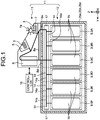
- FIG. 1 is a schematic view illustrating the banknote handling apparatus according to the embodiment.
- banknote handling apparatus 1 includes: a depositing section 5 through which a user deposits banknotes 3; a validation section 6 that validates banknotes 3, which are conveyed from the depositing section 5; a dispensing section 7 that dispenses banknotes 3 to users; and an upstream conveyance mechanism 8 including conveyance paths 8a that convey banknotes 3 among the depositing section 5, the validation section 6, and the dispensing section 7.
- the dispensing section 7 has an impeller 7a provided thereto that feeds out banknotes 3.
- the banknote handling apparatus 1 further includes a plurality of housing units 9 that houses banknotes 3, which are delivered from the validation section 6.
- the banknote handling apparatus 1 may include, as appropriate, a temporary housing section (not illustrated) that temporarily houses banknotes 3, which are deposited through the depositing section 5.
- the depositing section 5 and the dispensing section 7 may be configured as a single depositing and dispensing section (not illustrated). Any one of the housing units may be used as, for example, a backflow unit that houses banknotes 3 and delivers banknotes 3 to the dispensing section 7 or a collection unit that collects banknotes 3 that are abnormal and banknotes 3 that are deteriorated (damaged).
- a constituent part, in which the depositing section 5, the validation section 6, the dispensing section 7, and the upstream conveyance mechanism 8 are disposed, is configured as an upper device 11, and a constituent part, in which the housing units 9 are disposed, is configured as a lower device 12.
- the upper device 11 in the embodiment corresponds to a handling section according to the present application.
- the upper device 11 and each of housing units 9 in the lower device 12 are controlled by a controller 10.
- the upper device 11 and the lower device 12 are coupled together via two of the conveyance paths 8a, which are included in the upstream conveyance mechanism 8.
- a width direction of the banknote handling apparatus 1 is defined as an X-direction
- a forward or backward direction of the banknote handling apparatus 1 is defined as a Y-direction
- an upward or downward direction of the banknote handling apparatus 1 is defined as a Z-direction.
- the drawings that follow FIG. 1 are also illustrated with the X-direction, the Y-direction, and the Z-direction that are defined in the same manner as in FIG. 1 .
- banknotes 3 are used as an example of the paper sheets in the present embodiment, the paper sheets are not limited to banknotes 3. Examples of the paper sheets include securities such as bills, checks, gift certificates, securities of various types, and share certificates.
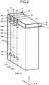
- FIG. 2 is a perspective view illustrating the housing units 9 that are included in the banknote handling apparatus 1 in the embodiment.
- FIG. 3 is a perspective view illustrating downstream conveyance mechanisms in the housing units 9 in the embodiment.
- each of the housing units 9 include: a downstream conveyance mechanism 14 that conveys banknotes 3, which are conveyed from the upper device 11; and a housing section 15 configured to house banknotes 3, which are conveyed by the downstream conveyance mechanisms 14.
- the individual housing units 9 are provided in such a manner that the downstream conveyance mechanisms 14 can be separated from the housing section 15.
- Each of the downstream conveyance mechanism 14 includes a conveyance path 14a that conveys banknotes 3, and the conveyance path 14a is provided with a gate member (not illustrated) that switches between paths, which convey banknotes 3.
- the controller 10 described above causes the gate member to switch therebetween, thereby controlling a path for banknotes 3 between a path, through which banknotes 3 are housed by a corresponding one of the housing sections 15 (a path through which banknotes 3 are delivered from the corresponding housing section 15), and a path, through which banknotes 3 are delivered to the conveyance path 14a in the downstream conveyance mechanism 14 that is provided in the next housing unit 9.
- housing units 9 9A to 9F are coupled together according to the present embodiment as illustrated in FIG. 1 .
- the three housing units 9A, 9B, and 9C disposed in the starting-end side (upstream side in the conveyance direction of a group of the downstream conveyance mechanisms 14) in the coupling direction of the housing units 9 (9A to 9F) (the Y-direction) are the housing units 9 that are previously included as a factory-default standard specification for the banknote handling apparatus 1.
- the housing unit 9F disposed in the terminal-end side (the most downstream side in the conveyance direction of a group of the downstream conveyance mechanisms 14) in the coupling direction of the housing units 9 (9A to 9F), is the housing unit 9 that is previously included as a factory-default standard specification for the banknote handling apparatus 1.
- the two housing units 9D and 9E coupled together between the housing unit 9C and the housing unit 9F are the housing units 9 that are optionally added (housing units 9 that are additionally installed). Accordingly, for another one of the housing units 9 to be added, the new housing unit 9 is disposed and coupled between the housing unit 9C and the housing unit 9F, for example, between the housing unit 9F and the housing unit 9E (see FIG. 5 ).
- the above configuration is merely an example, and is not intended to limit the number of housing units 9 included in the banknote handling apparatus 1 as standard specifications.
- the banknote handling apparatus 1 may include only two of the housing units 9 as a standard specification, the two being the housing unit 9 disposed at the starting end in the coupling direction (the Y-direction) of the housing units 9, and the housing unit 9 disposed at the terminal end in the coupling direction.
- the housing units 9 are configured so that each of the housing units 9 can be coupled to another one thereof via the downstream conveyance mechanisms 14 along the coupling direction (the Y-direction) of the housing units 9.
- the banknote handling apparatus 1 includes a coupling frame 20a and a coupling frame 20b.
- the coupling frame 20a couples together the downstream conveyance mechanisms 14 in the housing units 9A to 9C that are included as a standard specification.
- the coupling frame 20b is fixed to the downstream conveyance mechanism 14 in the housing unit 9F that is disposed at the terminal end in the coupling direction.
- the housing units 9D and 9E are provided with corresponding coupling frames 20c that are coupled to the downstream conveyance mechanisms 14 in the housing units 9, which are next to each other.
- Each of the housing units 9A and 9F which is disposed at both ends in the coupling direction of the housing units 9 (the Y-direction), includes a rotational support mechanism 17 that pivotably supports a group of the downstream conveyance mechanisms 14, which are coupled together, with respect to the group of the housing sections 15.
- the rotational support mechanism 17 includes a support frame 18, which is fixed to the corresponding downstream conveyance mechanism 14, and a rotational shaft 19, which is pivotably supported by the support frame 18.
- the rotational support mechanisms 17 are fixed to the coupling frames 20a and 20b.
- the group of the downstream conveyance mechanisms 14 is rotated about the rotational shafts 19 with respect to the group of the housing sections 15.
- the housing units 9B to 9E that are other than the housing units 9A and 9F, which are disposed at both ends in the coupling direction (the Y-direction), do not include the rotational support mechanisms 17 that allow the downstream conveyance mechanisms 14 to pivot with respect to the housing sections 15.
- the axial direction of the rotational shaft 19 that is included in the rotational support mechanism 17, is disposed along the coupling direction of the group of the downstream conveyance mechanisms 14 (the Y-direction). Increase in the size of a space occupied by the downstream conveyance mechanisms 14 in an unfolded state when being made to pivot with respect to the group of the housing sections 15, due to change in the number of the housing units9, can be thus suppressed.
- the coupling frames 20a, 20b, and 20c are coupled together via coupling members 22 and fastening members 23 such as screws, whereby the individual downstream conveyance mechanisms 14 in the housing units 9, are positioned in alignment with one another, and coupled in the coupling direction (the Y-direction).
- the group of the downstream conveyance mechanisms 14, which are connected together is coupled to the group of the housing sections 15 via the rotational support mechanisms 17 of the housing units 9A and 9F at both ends in the coupling direction in a manner that allows the group of the downstream conveyance mechanisms 14 to integrally pivot.
- the downstream conveyance mechanisms 14 in the individual housing units 9, include opening/closing mechanisms 24 that split the downstream conveyance mechanisms 14 along the conveyance paths 14a (see FIG. 7 ).
- the opening/closing mechanism 24 includes a rotational shaft 24a that extends in a direction (the X-direction) perpendicular to the coupling direction of the group of the downstream conveyance mechanisms 14 (the Y-direction).
- the conveyance paths 14a are split and opened by allowing lower parts of the conveyance paths 14a to pivot about the rotational shafts 24a.
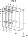
- FIG. 4 is a perspective view illustrating casings of the housing units 9 in the embodiment.
- the individual housing units 9 (9A to 9F) are provided with casings 25a, 25b, and 25c that are provided to the outer sides of the housing sections 15 as illustrated in FIG. 1 and FIG. 4 .
- the individual housing units 9A to 9C included in the banknote handling apparatus 1 as a standard specification are provided with the casing 25a, which is integrally formed.
- the housing unit 9F which is disposed at the terminal end in the coupling direction of the housing units 9 (the Y-direction), is provided with the casing 25b, which is formed so as to cover the terminal-end side of the conveyance paths 14a.
- the housing units 9D and 9E are provided with the corresponding casings 25c each coupled to the housing unit 9 that is adjacent thereto.
- the casings 25a, 25b, and 25c of the housing units 9 (9A to 9F) are coupled together via coupling members 26 and fastening members 27 such as screws, thereby collectively forming a box-like shape, and are configured as a part of an outer casing of the lower device 12.
- coupling members 26 and fastening members 27 such as screws
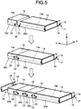
- FIG. 5 is a perspective view for explaining coupling of the downstream conveyance mechanisms 14 in the housing units 9 in the embodiment. As illustrated in FIG. 5 , when the housing units 9 (9A to 9F) are connected together in the coupling direction (the Y-direction), the group of the individual downstream conveyance mechanisms 14 is coupled together.
- the coupling frame 20c of the downstream conveyance mechanism 14 in the housing unit 9D is positioned in alignment with the coupling frame 20a of the downstream conveyance mechanisms 14 in the housing units 9A to 9C, and fixed thereto via the coupling member 22 and the fastening member 23.
- the coupling frames 20c of the downstream conveyance mechanisms 14 in the housing units 9D and 9E are positioned in alignment with each other and fixed to each other via the coupling member 22 and the fastening member 23.
- the coupling frame 20b of the downstream conveyance mechanism 14 in the housing unit 9F which is disposed at the terminal end, is positioned in alignment with the coupling frame 20c of the downstream conveyance mechanism 14 in the housing unit 9E, and fixed thereto via the coupling member 22 and the fastening member 23.
- the rotational support mechanism 17 is fixed to the downstream conveyance mechanism 14 of the housing unit 9F via the support frame 18.
- the downstream conveyance mechanisms 14 in the individual housing units 9 are thus coupled together while being positioned in alignment with one another, thereby being integrally pivotable about the rotational shafts 19 of the rotational support mechanisms 17.
- FIG. 6 is a perspective view for explaining coupling of the housing sections 15 in the housing units 9 in the embodiment.
- FIG. 6 omits illustration of the housing sections 15 for the sake of convenience.
- the individual housing sections 15 in the housing units 9 (9A to 9F) are coupled together via the casings 25a, 25b, and 25c.
- the casing 25c of the housing unit 9D is positioned in alignment with the casing 25a of the housing units 9A to 9C, and fixed thereto via the coupling members 26 and the fastening members 27.
- the casings 25c of the housing units 9D and 9E are positioned in alignment with each other, and fixed to each other via the coupling members 26 and the fastening members 27.
- the casing 25b of the housing unit 9F is positioned in alignment with the casing 25c of the housing unit 9E, and fixed thereto via the coupling members 26 and the fastening members 27.
- FIG. 7 is a perspective view for explaining operation of unfolding the downstream conveyance mechanisms 14 in the housing units 9 in the embodiment.
- the group of the downstream conveyance mechanism 14 is integrally rotated about the rotational shafts 19 of the rotational support mechanisms 17 with the downstream conveyance mechanisms 14 kept being coupled together.
- the group of the downstream conveyance mechanisms 14 is thereby integrally separated from the group of the housing sections 15.
- the conveyance paths 14a in the individual downstream conveyance mechanisms 14 in the group of the downstream conveyance mechanisms 14 that has been separated from the group of the housing sections 15 are individually opened via the opening/closing mechanisms 24, whereby maintenance is smoothly performed on the conveyance paths 14a.
- the conveyance paths 14a are opened and closed about the rotational shafts 24a perpendicular to the coupling direction of the downstream conveyance mechanisms 14 (the Y-direction), whereby increase in the size of a space occupied by the conveyance paths 14a in an unfolded state when being opened or closed about the rotational shafts 24a can be suppressed.
- each of the housing units 9, which includes the downstream conveyance mechanisms 14 and the housing sections 15, can be coupled to another one of the housing units 9 via the downstream conveyance mechanisms 14, and the group of the downstream conveyance mechanisms 14, which are coupled together, is coupled to the group of the housing sections 15 in a manner that allows the group of the downstream conveyance mechanisms 14 to integrally pivot.
- the housing units 9 are coupled together via the downstream conveyance mechanisms 14, whereby the number of housing units 9 can be easily changed.
- work of separating the downstream conveyance mechanisms 14 from the housing sections 15, is not needed to be performed with respect to each of the housing units 9.
- the group of the downstream conveyance mechanisms 14 can be collectively separated from the group of the housing sections 15, whereby maintenance is efficiently performed on the conveyance paths 14a in the group of the downstream conveyance mechanisms 14. Therefore, with the banknote handling apparatus 1, the number of housing units 9 can be easily changed, and the maintainability of the downstream conveyance mechanism 14 in each of the housing units 9, can be enhanced.
- the housing units 9A and 9F which are disposed at both ends among the housing units 9 (9A to 9F) in the coupling direction of the group of the downstream conveyance mechanisms 14 (the Y-direction), include the rotational support mechanisms 17 that pivotably support the downstream conveyance mechanisms 14 with respect to the housing sections 15.
- the group of the individual downstream conveyance mechanisms 14 in the housing units 9, is coupled together so as to be integrally pivotable via the rotational support mechanisms 17.
- the rotational support mechanisms 17 in the housing units 9A and 9F which are included in the banknote handling apparatus 1 according to the embodiment, include the rotational shafts 19, which are disposed along the coupling direction of the group of the downstream conveyance mechanisms 14 (the Y-direction). Increase in the size of a space occupied by the group of the downstream conveyance mechanisms 14 in an unfolded state, due to change in the number of the housing units 9 coupled together, can be thus suppressed.
- the downstream conveyance mechanisms 14 in the individual housing units 9 (9A to 9F) include the opening/closing mechanisms 24 that split the downstream conveyance mechanisms 14 along the conveyance paths 14a, and the opening/closing mechanisms 24 include the rotational shafts 24a, which extend in the direction (the X-direction) perpendicular to the coupling direction of the group of the downstream conveyance mechanisms 14 (the Y-direction).
- the rotational shaft 19 that allows the group of the downstream conveyance mechanisms 14 to integrally pivot and the rotational shaft 24a of the opening/closing mechanisms 24 are disposed perpendicular to each other.
- the individual conveyance paths 14a in the group of the downstream conveyance mechanisms 14 can be opened and closed within a compact range from a state, in which the group of the downstream conveyance mechanisms 14 is unfolded by the rotational support mechanism 17. This can suppress increase in the size of a space occupied by the conveyance paths 14a in an unfolded state. As a result, the maintainability of the downstream conveyance mechanisms 14 in the housing units 9 can be enhanced.
- the individual housing units 9 (9A to 9F), which are included in the banknote handling apparatus 1 according to the embodiment, include the downstream conveyance mechanisms 14, and the casings 25a, 25b, and 25c, which are provided on the outer sides of and the housing sections 15.
- the casings 25a, 25b, and 25c are coupled together.
- coupling of the housing units 9 is reinforced, and coupling of the housing units 9 can be enhanced in stability.
Landscapes
- Engineering & Computer Science (AREA)
- Mechanical Engineering (AREA)
- Physics & Mathematics (AREA)
- General Physics & Mathematics (AREA)
- Delivering By Means Of Belts And Rollers (AREA)
- Pile Receivers (AREA)
Abstract
Description
- The present invention relates to a paper sheet handling apparatus.
- As a banknote handling apparatus such as an automated teller machine (ATM), an apparatus including a housing device that houses deposited banknotes, is known. A banknote handling apparatus of this type includes, for example, a plurality of housing devices in accordance with the amount of banknotes to be handled, and the housing devices are coupled together via a conveyance mechanism that conveys banknotes.
- Patent Literature 1: Japanese Patent Publication Laid-open No.
2012-238137 - In the banknote handling apparatus described above, the number of needed housing devices changes depending on factors such as the environment of the handling of banknotes, and the number of housing devices therefore tends to subject to change as desired. For example, when a new housing device is added in the banknote handling apparatus, work needed for changing the number of housing devices, is complicated in a configuration that makes it unavoidable to extend a conveyance path of the conveyance mechanism and connect the conveyance mechanism to the new housing device. Against this inconvenience, simplification and speed-up of work for changing the number of housing devices is enabled by configuring each housing device as a housing unit that includes a housing section and a conveyance mechanism and coupling the housing units together via the conveyance mechanisms.
- When maintenance is performed on conveyance paths that are coupled between the adjacent housing units, however, the maintainability of the conveyance mechanisms of the individual coupled housing units, is lowered as a result of the maintenance work that is performed with a conveyance path of the individual conveyance mechanism opened and closed with respect to each housing unit.
- The technique disclosed herein has been developed in consideration of the foregoing inconvenience and is directed to providing a paper sheet handling apparatus that enables easy change of the number of housing units and allows for enhanced maintainability of a conveyance mechanism in each housing unit.
- To solve the above problem and attain the object, a paper sheet handling apparatus disclosed in this application, according to an aspect, includes: a handling section including an upstream conveyance mechanism and a validation section, the upstream conveyance mechanism that conveys paper sheets, the validation section that validates paper sheets, which are conveyed by the upstream conveyance mechanism; and a plurality of housing units each including a downstream conveyance mechanism and a housing section, the downstream conveyance mechanism that conveys paper sheets conveyed from the handling section, the housing section that houses paper sheets, which are conveyed by the downstream conveyance mechanism, wherein each of the housing units is capable of being coupled to another one of the housing units via the downstream conveyance mechanisms, and a group of the downstream conveyance mechanisms, which are coupled together, is coupled to a group of the housing sections in a manner that allows the group of the downstream conveyance mechanisms to integrally pivot with respect to the group of the housing sections.
- According to an aspect of the paper sheet handling apparatus that is disclosed by the present application, the number of housing units can be easily changed, and the maintainability of a conveyance mechanism in each housing unit can be enhanced.
-
-
FIG. 1 is a schematic view illustrating a banknote handling apparatus according to an embodiment. -
FIG. 2 is a perspective view illustrating housing units that are included in the banknote handling apparatus in the embodiment. -
FIG. 3 is a perspective view illustrating downstream conveyance mechanisms in the housing unit in the embodiment. -
FIG. 4 is a perspective view illustrating casings of the housing units in the embodiment. -
FIG. 5 is a perspective view for explaining coupling of the downstream conveyance mechanisms in the housing units in the embodiment. -
FIG. 6 is a perspective view for explaining coupling of the housing sections in the housing units in the embodiment. -
FIG. 7 is a perspective view for explaining operation of unfolding the downstream conveyance mechanisms in the housing units in the embodiment. - An embodiment of a paper sheet handling apparatus that is disclosed by the present application, is described below in detail based on the drawings. The embodiment described below is not intended to limit the paper sheet handling apparatus that is disclosed by the present application.
-
FIG. 1 is a schematic view illustrating the banknote handling apparatus according to the embodiment. As illustrated inFIG. 1 , banknote handling apparatus 1 according to the embodiment includes: a depositingsection 5 through which auser deposits banknotes 3; avalidation section 6 that validatesbanknotes 3, which are conveyed from the depositingsection 5; adispensing section 7 that dispensesbanknotes 3 to users; and an upstream conveyance mechanism 8 includingconveyance paths 8a that conveybanknotes 3 among thedepositing section 5, thevalidation section 6, and thedispensing section 7. Thedispensing section 7 has animpeller 7a provided thereto that feeds outbanknotes 3. The banknote handling apparatus 1 further includes a plurality of housing units 9 that housesbanknotes 3, which are delivered from thevalidation section 6. - The banknote handling apparatus 1 according to the present embodiment may include, as appropriate, a temporary housing section (not illustrated) that temporarily houses
banknotes 3, which are deposited through the depositingsection 5. Thedepositing section 5 and thedispensing section 7 may be configured as a single depositing and dispensing section (not illustrated). Any one of the housing units may be used as, for example, a backflow unit that housesbanknotes 3 and deliversbanknotes 3 to thedispensing section 7 or a collection unit that collectsbanknotes 3 that are abnormal andbanknotes 3 that are deteriorated (damaged). - Of the banknote handling apparatus 1 according to the embodiment, a constituent part, in which the depositing
section 5, thevalidation section 6, thedispensing section 7, and the upstream conveyance mechanism 8 are disposed, is configured as anupper device 11, and a constituent part, in which the housing units 9 are disposed, is configured as alower device 12. Theupper device 11 in the embodiment corresponds to a handling section according to the present application. Theupper device 11 and each of housing units 9 in thelower device 12 are controlled by acontroller 10. Theupper device 11 and thelower device 12 are coupled together via two of theconveyance paths 8a, which are included in the upstream conveyance mechanism 8. - For convenience of explanation, with respect to the banknote handling apparatus 1, viewed from one side thereof, having the depositing
section 5 inFIG. 1 , a width direction of the banknote handling apparatus 1, is defined as an X-direction, a forward or backward direction of the banknote handling apparatus 1, is defined as a Y-direction, and an upward or downward direction of the banknote handling apparatus 1, is defined as a Z-direction. The drawings that followFIG. 1 are also illustrated with the X-direction, the Y-direction, and the Z-direction that are defined in the same manner as inFIG. 1 . Whilebanknotes 3 are used as an example of the paper sheets in the present embodiment, the paper sheets are not limited tobanknotes 3. Examples of the paper sheets include securities such as bills, checks, gift certificates, securities of various types, and share certificates. -
FIG. 2 is a perspective view illustrating the housing units 9 that are included in the banknote handling apparatus 1 in the embodiment.FIG. 3 is a perspective view illustrating downstream conveyance mechanisms in the housing units 9 in the embodiment. As illustrated inFIG. 1 ,FIG. 2 , andFIG. 3 , each of the housing units 9 include: adownstream conveyance mechanism 14 that conveysbanknotes 3, which are conveyed from theupper device 11; and ahousing section 15 configured to housebanknotes 3, which are conveyed by thedownstream conveyance mechanisms 14. - The individual housing units 9 are provided in such a manner that the
downstream conveyance mechanisms 14 can be separated from thehousing section 15. Each of thedownstream conveyance mechanism 14 includes aconveyance path 14a that conveysbanknotes 3, and theconveyance path 14a is provided with a gate member (not illustrated) that switches between paths, which conveybanknotes 3. Thecontroller 10 described above causes the gate member to switch therebetween, thereby controlling a path forbanknotes 3 between a path, through whichbanknotes 3 are housed by a corresponding one of the housing sections 15 (a path through whichbanknotes 3 are delivered from the corresponding housing section 15), and a path, through whichbanknotes 3 are delivered to theconveyance path 14a in thedownstream conveyance mechanism 14 that is provided in the next housing unit 9. - In the banknote handling apparatus 1 given as an example, six housing units 9 (9A to 9F) are coupled together according to the present embodiment as illustrated in
FIG. 1 . Among those six housing units 9, the three housing units 9A, 9B, and 9C disposed in the starting-end side (upstream side in the conveyance direction of a group of the downstream conveyance mechanisms 14) in the coupling direction of the housing units 9 (9A to 9F) (the Y-direction), are the housing units 9 that are previously included as a factory-default standard specification for the banknote handling apparatus 1. Among the six housing units 9 (9A to 9F) in the banknote handling apparatus 1, the housing unit 9F disposed in the terminal-end side (the most downstream side in the conveyance direction of a group of the downstream conveyance mechanisms 14) in the coupling direction of the housing units 9 (9A to 9F), is the housing unit 9 that is previously included as a factory-default standard specification for the banknote handling apparatus 1. - In contrast, among the six housing units 9 (9A to 9F) in the banknote handling apparatus 1, the two housing units 9D and 9E coupled together between the housing unit 9C and the housing unit 9F, are the housing units 9 that are optionally added (housing units 9 that are additionally installed). Accordingly, for another one of the housing units 9 to be added, the new housing unit 9 is disposed and coupled between the housing unit 9C and the housing unit 9F, for example, between the housing unit 9F and the housing unit 9E (see
FIG. 5 ). For the number of the housing units 9 to be reduced, any one of the two housing units 9D and 9E disposed between the housing unit 9C and the housing unit 9F, is removed, or, the two housing units 9D and 9E are removed, and the housing unit 9C and the housing unit 9F are then coupled together. - The above configuration is merely an example, and is not intended to limit the number of housing units 9 included in the banknote handling apparatus 1 as standard specifications. The banknote handling apparatus 1 may include only two of the housing units 9 as a standard specification, the two being the housing unit 9 disposed at the starting end in the coupling direction (the Y-direction) of the housing units 9, and the housing unit 9 disposed at the terminal end in the coupling direction.
- As illustrated in
FIG. 2 andFIG. 3 , the housing units 9 are configured so that each of the housing units 9 can be coupled to another one thereof via thedownstream conveyance mechanisms 14 along the coupling direction (the Y-direction) of the housing units 9. The banknote handling apparatus 1 according to the embodiment includes acoupling frame 20a and acoupling frame 20b. Thecoupling frame 20a couples together thedownstream conveyance mechanisms 14 in the housing units 9A to 9C that are included as a standard specification. Thecoupling frame 20b is fixed to thedownstream conveyance mechanism 14 in the housing unit 9F that is disposed at the terminal end in the coupling direction. The housing units 9D and 9E are provided withcorresponding coupling frames 20c that are coupled to thedownstream conveyance mechanisms 14 in the housing units 9, which are next to each other. - Each of the housing units 9A and 9F, which is disposed at both ends in the coupling direction of the housing units 9 (the Y-direction), includes a
rotational support mechanism 17 that pivotably supports a group of thedownstream conveyance mechanisms 14, which are coupled together, with respect to the group of thehousing sections 15. Therotational support mechanism 17 includes asupport frame 18, which is fixed to the correspondingdownstream conveyance mechanism 14, and arotational shaft 19, which is pivotably supported by thesupport frame 18. Therotational support mechanisms 17 are fixed to the coupling frames 20a and 20b. The group of thedownstream conveyance mechanisms 14 is rotated about therotational shafts 19 with respect to the group of thehousing sections 15. - In other words, the housing units 9B to 9E that are other than the housing units 9A and 9F, which are disposed at both ends in the coupling direction (the Y-direction), do not include the
rotational support mechanisms 17 that allow thedownstream conveyance mechanisms 14 to pivot with respect to thehousing sections 15. Thus eliminating therotational support mechanisms 17, results in a simplified configuration. - The axial direction of the
rotational shaft 19 that is included in therotational support mechanism 17, is disposed along the coupling direction of the group of the downstream conveyance mechanisms 14 (the Y-direction). Increase in the size of a space occupied by thedownstream conveyance mechanisms 14 in an unfolded state when being made to pivot with respect to the group of thehousing sections 15, due to change in the number of the housing units9, can be thus suppressed. - As illustrated in
FIG. 2 andFIG. 3 , thecoupling frames coupling members 22 andfastening members 23 such as screws, whereby the individualdownstream conveyance mechanisms 14 in the housing units 9, are positioned in alignment with one another, and coupled in the coupling direction (the Y-direction). Accordingly, the group of thedownstream conveyance mechanisms 14, which are connected together, is coupled to the group of thehousing sections 15 via therotational support mechanisms 17 of the housing units 9A and 9F at both ends in the coupling direction in a manner that allows the group of thedownstream conveyance mechanisms 14 to integrally pivot. - The
downstream conveyance mechanisms 14 in the individual housing units 9, include opening/closing mechanisms 24 that split thedownstream conveyance mechanisms 14 along theconveyance paths 14a (seeFIG. 7 ). The opening/closing mechanism 24 includes arotational shaft 24a that extends in a direction (the X-direction) perpendicular to the coupling direction of the group of the downstream conveyance mechanisms 14 (the Y-direction). In the group of thedownstream conveyance mechanisms 14, theconveyance paths 14a are split and opened by allowing lower parts of theconveyance paths 14a to pivot about therotational shafts 24a. -
FIG. 4 is a perspective view illustrating casings of the housing units 9 in the embodiment. The individual housing units 9 (9A to 9F) are provided withcasings housing sections 15 as illustrated inFIG. 1 andFIG. 4 . The individual housing units 9A to 9C included in the banknote handling apparatus 1 as a standard specification, are provided with thecasing 25a, which is integrally formed. The housing unit 9F, which is disposed at the terminal end in the coupling direction of the housing units 9 (the Y-direction), is provided with thecasing 25b, which is formed so as to cover the terminal-end side of theconveyance paths 14a. The housing units 9D and 9E are provided with the correspondingcasings 25c each coupled to the housing unit 9 that is adjacent thereto. - The
casings coupling members 26 andfastening members 27 such as screws, thereby collectively forming a box-like shape, and are configured as a part of an outer casing of thelower device 12. With the housing units 9 thus coupled together via thecasings downstream conveyance mechanisms 14 is enhanced in stability. -
FIG. 5 is a perspective view for explaining coupling of thedownstream conveyance mechanisms 14 in the housing units 9 in the embodiment. As illustrated inFIG. 5 , when the housing units 9 (9A to 9F) are connected together in the coupling direction (the Y-direction), the group of the individualdownstream conveyance mechanisms 14 is coupled together. - First, the
coupling frame 20c of thedownstream conveyance mechanism 14 in the housing unit 9D is positioned in alignment with thecoupling frame 20a of thedownstream conveyance mechanisms 14 in the housing units 9A to 9C, and fixed thereto via thecoupling member 22 and thefastening member 23. Through the same procedure as above, the coupling frames 20c of thedownstream conveyance mechanisms 14 in the housing units 9D and 9E are positioned in alignment with each other and fixed to each other via thecoupling member 22 and thefastening member 23. Finally, thecoupling frame 20b of thedownstream conveyance mechanism 14 in the housing unit 9F, which is disposed at the terminal end, is positioned in alignment with thecoupling frame 20c of thedownstream conveyance mechanism 14 in the housing unit 9E, and fixed thereto via thecoupling member 22 and thefastening member 23. Therotational support mechanism 17 is fixed to thedownstream conveyance mechanism 14 of the housing unit 9F via thesupport frame 18. Thedownstream conveyance mechanisms 14 in the individual housing units 9 are thus coupled together while being positioned in alignment with one another, thereby being integrally pivotable about therotational shafts 19 of therotational support mechanisms 17. -
FIG. 6 is a perspective view for explaining coupling of thehousing sections 15 in the housing units 9 in the embodiment.FIG. 6 omits illustration of thehousing sections 15 for the sake of convenience. As illustrated inFIG. 6 , theindividual housing sections 15 in the housing units 9 (9A to 9F) are coupled together via thecasings - First, the
casing 25c of the housing unit 9D is positioned in alignment with thecasing 25a of the housing units 9A to 9C, and fixed thereto via thecoupling members 26 and thefastening members 27. Through the same procedure as above, thecasings 25c of the housing units 9D and 9E are positioned in alignment with each other, and fixed to each other via thecoupling members 26 and thefastening members 27. Finally, thecasing 25b of the housing unit 9F is positioned in alignment with thecasing 25c of the housing unit 9E, and fixed thereto via thecoupling members 26 and thefastening members 27. With theindividual housing sections 15 thus coupled together via thecasings -
FIG. 7 is a perspective view for explaining operation of unfolding thedownstream conveyance mechanisms 14 in the housing units 9 in the embodiment. As illustrated inFIG. 7 , when maintenance is performed on theconveyance paths 14a in thedownstream conveyance mechanisms 14, the group of thedownstream conveyance mechanism 14 is integrally rotated about therotational shafts 19 of therotational support mechanisms 17 with thedownstream conveyance mechanisms 14 kept being coupled together. The group of thedownstream conveyance mechanisms 14 is thereby integrally separated from the group of thehousing sections 15. - Subsequently, the
conveyance paths 14a in the individualdownstream conveyance mechanisms 14 in the group of thedownstream conveyance mechanisms 14 that has been separated from the group of thehousing sections 15 are individually opened via the opening/closing mechanisms 24, whereby maintenance is smoothly performed on theconveyance paths 14a. During this maintenance, theconveyance paths 14a are opened and closed about therotational shafts 24a perpendicular to the coupling direction of the downstream conveyance mechanisms 14 (the Y-direction), whereby increase in the size of a space occupied by theconveyance paths 14a in an unfolded state when being opened or closed about therotational shafts 24a can be suppressed. - As described above, in the banknote handling apparatus 1 according to the embodiment, each of the housing units 9, which includes the
downstream conveyance mechanisms 14 and thehousing sections 15, can be coupled to another one of the housing units 9 via thedownstream conveyance mechanisms 14, and the group of thedownstream conveyance mechanisms 14, which are coupled together, is coupled to the group of thehousing sections 15 in a manner that allows the group of thedownstream conveyance mechanisms 14 to integrally pivot. With the banknote handling apparatus 1, the housing units 9 are coupled together via thedownstream conveyance mechanisms 14, whereby the number of housing units 9 can be easily changed. When maintenance is performed on the housing units 9, work of separating thedownstream conveyance mechanisms 14 from thehousing sections 15, is not needed to be performed with respect to each of the housing units 9. Instead, the group of thedownstream conveyance mechanisms 14 can be collectively separated from the group of thehousing sections 15, whereby maintenance is efficiently performed on theconveyance paths 14a in the group of thedownstream conveyance mechanisms 14. Therefore, with the banknote handling apparatus 1, the number of housing units 9 can be easily changed, and the maintainability of thedownstream conveyance mechanism 14 in each of the housing units 9, can be enhanced. - In the banknote handling apparatus 1 according to the embodiment, the housing units 9A and 9F, which are disposed at both ends among the housing units 9 (9A to 9F) in the coupling direction of the group of the downstream conveyance mechanisms 14 (the Y-direction), include the
rotational support mechanisms 17 that pivotably support thedownstream conveyance mechanisms 14 with respect to thehousing sections 15. The group of the individualdownstream conveyance mechanisms 14 in the housing units 9, is coupled together so as to be integrally pivotable via therotational support mechanisms 17. Only the housing units 9A and 9F at both ends in the coupling direction of the housing units 9 (9A to 9F) thus, include therotational support mechanisms 17, whereby therotational support mechanisms 17 can be eliminated from the individual housing units 9B to 9E, which are disposed between the housing units 9A and 9F at both ends, and the configurations of the housing units 9E and 9F optionally added, can be simplified. - The
rotational support mechanisms 17 in the housing units 9A and 9F, which are included in the banknote handling apparatus 1 according to the embodiment, include therotational shafts 19, which are disposed along the coupling direction of the group of the downstream conveyance mechanisms 14 (the Y-direction). Increase in the size of a space occupied by the group of thedownstream conveyance mechanisms 14 in an unfolded state, due to change in the number of the housing units 9 coupled together, can be thus suppressed. - In the banknote handling apparatus 1 according to the embodiment, the
downstream conveyance mechanisms 14 in the individual housing units 9 (9A to 9F) include the opening/closing mechanisms 24 that split thedownstream conveyance mechanisms 14 along theconveyance paths 14a, and the opening/closing mechanisms 24 include therotational shafts 24a, which extend in the direction (the X-direction) perpendicular to the coupling direction of the group of the downstream conveyance mechanisms 14 (the Y-direction). Thus, therotational shaft 19 that allows the group of thedownstream conveyance mechanisms 14 to integrally pivot and therotational shaft 24a of the opening/closing mechanisms 24 are disposed perpendicular to each other. Therefore, theindividual conveyance paths 14a in the group of thedownstream conveyance mechanisms 14 can be opened and closed within a compact range from a state, in which the group of thedownstream conveyance mechanisms 14 is unfolded by therotational support mechanism 17. This can suppress increase in the size of a space occupied by theconveyance paths 14a in an unfolded state. As a result, the maintainability of thedownstream conveyance mechanisms 14 in the housing units 9 can be enhanced. - The individual housing units 9 (9A to 9F), which are included in the banknote handling apparatus 1 according to the embodiment, include the
downstream conveyance mechanisms 14, and thecasings housing sections 15. Thecasings -
- 3
- BANKNOTES (PAPER SHEETS)
- 6
- VALIDATION SECTION
- 8
- UPSTREAM CONVEYANCE MECHANISM
- 9
- HOUSING UNIT
- 11
- UPPER DEVICE (HANDLING SECTION)
- 12
- LOWER DEVICE
- 14
- DOWNSTREAM CONVEYANCE MECHANISM
- 14a
- CONVEYANCE PATH
- 15
- HOUSING SECTION
- 17
- ROTATIONAL SUPPORT MECHANISM
- 19
- ROTATIONAL SHAFT
- 24
- OPENING/CLOSING MECHANISM
- 24a
- ROTATIONAL SHAFT
Claims (5)
- A paper sheet handling apparatus comprising:a handling section including an upstream conveyance mechanism and a validation section, the upstream conveyance mechanism that conveys paper sheets, the validation section that validates paper sheets, which are conveyed by the upstream conveyance mechanism; anda plurality of housing units each including a downstream conveyance mechanism and a housing section, the downstream conveyance mechanism that conveys paper sheets conveyed from the handling section, the housing section that houses paper sheets, which are conveyed by the downstream conveyance mechanism, whereineach of the housing units is capable of being coupled to another one of the housing units via the downstream conveyance mechanisms, and a group of the downstream conveyance mechanisms, which are coupled together, is coupled to a group of the housing sections in a manner that allows the group of the downstream conveyance mechanisms to integrally pivot with respect to the group of the housing sections.
- The paper sheet handling apparatus according to claim 1, wherein
each of the housing units, which are disposed at both ends among the housing units in a coupling direction of a group of the downstream conveyance mechanisms, includes a rotational support mechanism that pivotably supports the downstream conveyance mechanisms with respect to the housing sections, and
a group of the individual downstream conveyance mechanisms in the housing units is coupled together so as to be integrally pivotable via the rotational support mechanisms. - The paper sheet handling apparatus according to claim 2, wherein the rotational support mechanism includes a rotational shaft that is disposed along a coupling direction of the group of the downstream conveyance mechanisms.
- The paper sheet handling apparatus according to claim 3, wherein
the downstream conveyance mechanism in each of the housing units includes an opening/closing mechanism that splits the downstream conveyance mechanism along a conveyance path, and
the opening/closing mechanism includes a rotational shaft that extends in a direction perpendicular to the coupling direction of the group of the downstream conveyance mechanisms. - The paper sheet handling apparatus according to claim 1, wherein the housing units are individually provided with casings that are provided to outer sides of the housing sections, and the casings are coupled together.
Applications Claiming Priority (1)
| Application Number | Priority Date | Filing Date | Title |
|---|---|---|---|
| PCT/JP2018/011160 WO2019180842A1 (en) | 2018-03-20 | 2018-03-20 | Paper sheet handling device |
Publications (3)
| Publication Number | Publication Date |
|---|---|
| EP3770869A1 true EP3770869A1 (en) | 2021-01-27 |
| EP3770869A4 EP3770869A4 (en) | 2021-04-14 |
| EP3770869B1 EP3770869B1 (en) | 2025-11-05 |
Family
ID=67986896
Family Applications (1)
| Application Number | Title | Priority Date | Filing Date |
|---|---|---|---|
| EP18910515.8A Active EP3770869B1 (en) | 2018-03-20 | 2018-03-20 | Paper sheet handling device |
Country Status (5)
| Country | Link |
|---|---|
| US (1) | US11505422B2 (en) |
| EP (1) | EP3770869B1 (en) |
| JP (1) | JP6860741B2 (en) |
| CN (1) | CN111868794B (en) |
| WO (1) | WO2019180842A1 (en) |
Families Citing this family (1)
| Publication number | Priority date | Publication date | Assignee | Title |
|---|---|---|---|---|
| CN110626696B (en) * | 2019-10-10 | 2024-08-30 | 维融科技股份有限公司 | A movement and its multi-currency dispensing line |
Family Cites Families (18)
| Publication number | Priority date | Publication date | Assignee | Title |
|---|---|---|---|---|
| JPH06325241A (en) * | 1993-05-11 | 1994-11-25 | Nippon Conlux Co Ltd | Paper money processor |
| JPH09235061A (en) * | 1996-03-01 | 1997-09-09 | Omron Corp | Paper storage device and transaction processing device |
| US7201320B2 (en) * | 2000-02-11 | 2007-04-10 | Cummins-Allison Corp. | System and method for processing currency bills and documents bearing barcodes in a document processing device |
| JP4048209B2 (en) | 2000-07-17 | 2008-02-20 | 日本金銭機械株式会社 | Banknote handling equipment |
| US8016186B2 (en) * | 2006-02-03 | 2011-09-13 | Nautilus Hyosung Inc. | Automated teller machine having a cassette apparatus |
| JP4654268B2 (en) * | 2008-05-28 | 2011-03-16 | 日立オムロンターミナルソリューションズ株式会社 | Banknote deposit and withdrawal device |
| JP5284843B2 (en) * | 2009-03-27 | 2013-09-11 | 富士通フロンテック株式会社 | Paper sheet processing equipment |
| JP5280976B2 (en) * | 2009-08-31 | 2013-09-04 | 富士通フロンテック株式会社 | Paper handling equipment |
| CN103168318B (en) * | 2010-10-27 | 2015-09-30 | 日立欧姆龙金融系统有限公司 | Bill handling device and cash automated trading device |
| JP5742451B2 (en) | 2011-05-11 | 2015-07-01 | 沖電気工業株式会社 | Banknote deposit and withdrawal device |
| JP5527347B2 (en) * | 2012-03-26 | 2014-06-18 | 沖電気工業株式会社 | Paper sheet storage and paper sheet handling device |
| JP5949487B2 (en) * | 2012-11-16 | 2016-07-06 | 沖電気工業株式会社 | Paper sheet conveying device and paper sheet handling device |
| CN103985188A (en) * | 2014-05-28 | 2014-08-13 | 昆山古鳌电子机械有限公司 | Paper money output and input device |
| JP6794697B2 (en) * | 2016-07-21 | 2020-12-02 | 沖電気工業株式会社 | Media processing equipment and media trading equipment |
| TWI607416B (en) * | 2016-12-08 | 2017-12-01 | Masterwork Automodules Tech Corp Ltd | Paper sheet handling apparatus |
| CN206581728U (en) * | 2017-01-20 | 2017-10-24 | 广州广电运通金融电子股份有限公司 | Financial self-service equipment and movement safeguard locker |
| CN107481410B (en) * | 2017-09-30 | 2023-09-08 | 深圳怡化电脑股份有限公司 | Lower core and self-service financial terminal |
| CN107689102B (en) * | 2017-09-30 | 2023-11-14 | 深圳怡化电脑股份有限公司 | Lower core and financial equipment |
-
2018
- 2018-03-20 JP JP2020507188A patent/JP6860741B2/en active Active
- 2018-03-20 WO PCT/JP2018/011160 patent/WO2019180842A1/en not_active Ceased
- 2018-03-20 CN CN201880091296.9A patent/CN111868794B/en active Active
- 2018-03-20 EP EP18910515.8A patent/EP3770869B1/en active Active
-
2020
- 2020-09-11 US US17/018,263 patent/US11505422B2/en active Active
Also Published As
| Publication number | Publication date |
|---|---|
| CN111868794A (en) | 2020-10-30 |
| JPWO2019180842A1 (en) | 2020-10-22 |
| EP3770869B1 (en) | 2025-11-05 |
| WO2019180842A1 (en) | 2019-09-26 |
| JP6860741B2 (en) | 2021-04-21 |
| US20200407186A1 (en) | 2020-12-31 |
| EP3770869A4 (en) | 2021-04-14 |
| US11505422B2 (en) | 2022-11-22 |
| CN111868794B (en) | 2022-05-13 |
Similar Documents
| Publication | Publication Date | Title |
|---|---|---|
| TWI336684B (en) | The switching gate for the conveyance path of paper and the automatic teller machine | |
| KR101723285B1 (en) | Paper money processing device, paper money processing system, and paper money conveyance device | |
| US8579279B2 (en) | Conveying direction-switching device for paper leaves with direction-changing drum | |
| US11505422B2 (en) | Paper sheet handling apparatus | |
| EP2890099B1 (en) | Document reading device | |
| CN103930932A (en) | Cash Drawer with Dual Roller Storage | |
| KR101250657B1 (en) | Medium cassette and financial device | |
| US20210192879A1 (en) | Automated teller machine and medium conveyance route switching device for automated teller machine | |
| EP1736937A1 (en) | Cash withdrawing apparatus of an automated teller machine | |
| KR20140085679A (en) | Apparatus for receiving and dispensing bill | |
| JP6770575B2 (en) | Front-back reversing device, paper leaf processing machine and front-back reversing method | |
| US12230090B2 (en) | Sheet storage device | |
| KR101719765B1 (en) | Automatic teller machine and gate apparatus for guiding bills thereof | |
| US20170256112A1 (en) | Paper sheet handling apparatus | |
| KR102323435B1 (en) | Automated teller machine and apparatus for changing of bill transferring direction threrof | |
| CN110077875A (en) | Processing unit and image forming apparatus | |
| US10621808B1 (en) | Media diverter and valuable media depository | |
| US5649892A (en) | Apparatus and method for conveying a sheet | |
| KR20160001939A (en) | medium path changing apparatus and financial device | |
| KR20110069961A (en) | Open Structure of Banknote Module | |
| KR102312912B1 (en) | Apparatus for changing of the bill transferring direction in automated teller machine | |
| KR102236775B1 (en) | Apparatus for changing of the bill transferring direction in automated teller machine | |
| CN112567433A (en) | Paper money processing device | |
| JP2024025420A (en) | Money handling device, money handling device manufacturing method, and program | |
| WO2023081836A1 (en) | Jam clearance mechanism for banknote feeder |
Legal Events
| Date | Code | Title | Description |
|---|---|---|---|
| STAA | Information on the status of an ep patent application or granted ep patent |
Free format text: STATUS: THE INTERNATIONAL PUBLICATION HAS BEEN MADE |
|
| PUAI | Public reference made under article 153(3) epc to a published international application that has entered the european phase |
Free format text: ORIGINAL CODE: 0009012 |
|
| STAA | Information on the status of an ep patent application or granted ep patent |
Free format text: STATUS: REQUEST FOR EXAMINATION WAS MADE |
|
| 17P | Request for examination filed |
Effective date: 20200911 |
|
| AK | Designated contracting states |
Kind code of ref document: A1 Designated state(s): AL AT BE BG CH CY CZ DE DK EE ES FI FR GB GR HR HU IE IS IT LI LT LU LV MC MK MT NL NO PL PT RO RS SE SI SK SM TR |
|
| AX | Request for extension of the european patent |
Extension state: BA ME |
|
| A4 | Supplementary search report drawn up and despatched |
Effective date: 20210312 |
|
| RIC1 | Information provided on ipc code assigned before grant |
Ipc: G07D 9/00 20060101AFI20210305BHEP Ipc: G07D 11/40 20190101ALI20210305BHEP |
|
| DAV | Request for validation of the european patent (deleted) | ||
| DAX | Request for extension of the european patent (deleted) | ||
| STAA | Information on the status of an ep patent application or granted ep patent |
Free format text: STATUS: EXAMINATION IS IN PROGRESS |
|
| 17Q | First examination report despatched |
Effective date: 20230228 |
|
| GRAP | Despatch of communication of intention to grant a patent |
Free format text: ORIGINAL CODE: EPIDOSNIGR1 |
|
| STAA | Information on the status of an ep patent application or granted ep patent |
Free format text: STATUS: GRANT OF PATENT IS INTENDED |
|
| INTG | Intention to grant announced |
Effective date: 20250703 |
|
| GRAS | Grant fee paid |
Free format text: ORIGINAL CODE: EPIDOSNIGR3 |
|
| GRAA | (expected) grant |
Free format text: ORIGINAL CODE: 0009210 |
|
| STAA | Information on the status of an ep patent application or granted ep patent |
Free format text: STATUS: THE PATENT HAS BEEN GRANTED |
|
| AK | Designated contracting states |
Kind code of ref document: B1 Designated state(s): AL AT BE BG CH CY CZ DE DK EE ES FI FR GB GR HR HU IE IS IT LI LT LU LV MC MK MT NL NO PL PT RO RS SE SI SK SM TR |
|
| REG | Reference to a national code |
Ref country code: CH Ref legal event code: F10 Free format text: ST27 STATUS EVENT CODE: U-0-0-F10-F00 (AS PROVIDED BY THE NATIONAL OFFICE) Effective date: 20251105 Ref country code: GB Ref legal event code: FG4D |
|
| REG | Reference to a national code |
Ref country code: DE Ref legal event code: R096 Ref document number: 602018087033 Country of ref document: DE |
|
| REG | Reference to a national code |
Ref country code: IE Ref legal event code: FG4D |
|
| REG | Reference to a national code |
Ref country code: NL Ref legal event code: MP Effective date: 20251105 |
|
| PGFP | Annual fee paid to national office [announced via postgrant information from national office to epo] |
Ref country code: GB Payment date: 20260309 Year of fee payment: 9 |
|
| PG25 | Lapsed in a contracting state [announced via postgrant information from national office to epo] |
Ref country code: ES Free format text: LAPSE BECAUSE OF FAILURE TO SUBMIT A TRANSLATION OF THE DESCRIPTION OR TO PAY THE FEE WITHIN THE PRESCRIBED TIME-LIMIT Effective date: 20251105 |
|
| REG | Reference to a national code |
Ref country code: LT Ref legal event code: MG9D |
|
| PG25 | Lapsed in a contracting state [announced via postgrant information from national office to epo] |
Ref country code: NO Free format text: LAPSE BECAUSE OF FAILURE TO SUBMIT A TRANSLATION OF THE DESCRIPTION OR TO PAY THE FEE WITHIN THE PRESCRIBED TIME-LIMIT Effective date: 20260205 |
|
| PG25 | Lapsed in a contracting state [announced via postgrant information from national office to epo] |
Ref country code: AT Free format text: LAPSE BECAUSE OF FAILURE TO SUBMIT A TRANSLATION OF THE DESCRIPTION OR TO PAY THE FEE WITHIN THE PRESCRIBED TIME-LIMIT Effective date: 20251105 Ref country code: HR Free format text: LAPSE BECAUSE OF FAILURE TO SUBMIT A TRANSLATION OF THE DESCRIPTION OR TO PAY THE FEE WITHIN THE PRESCRIBED TIME-LIMIT Effective date: 20251105 Ref country code: FI Free format text: LAPSE BECAUSE OF FAILURE TO SUBMIT A TRANSLATION OF THE DESCRIPTION OR TO PAY THE FEE WITHIN THE PRESCRIBED TIME-LIMIT Effective date: 20251105 |
|
| REG | Reference to a national code |
Ref country code: AT Ref legal event code: MK05 Ref document number: 1855241 Country of ref document: AT Kind code of ref document: T Effective date: 20251105 |
|
| PG25 | Lapsed in a contracting state [announced via postgrant information from national office to epo] |
Ref country code: NL Free format text: LAPSE BECAUSE OF FAILURE TO SUBMIT A TRANSLATION OF THE DESCRIPTION OR TO PAY THE FEE WITHIN THE PRESCRIBED TIME-LIMIT Effective date: 20251105 |
|
| PG25 | Lapsed in a contracting state [announced via postgrant information from national office to epo] |
Ref country code: RS Free format text: LAPSE BECAUSE OF FAILURE TO SUBMIT A TRANSLATION OF THE DESCRIPTION OR TO PAY THE FEE WITHIN THE PRESCRIBED TIME-LIMIT Effective date: 20260205 |
|
| PG25 | Lapsed in a contracting state [announced via postgrant information from national office to epo] |
Ref country code: IS Free format text: LAPSE BECAUSE OF FAILURE TO SUBMIT A TRANSLATION OF THE DESCRIPTION OR TO PAY THE FEE WITHIN THE PRESCRIBED TIME-LIMIT Effective date: 20260305 |
|
| PG25 | Lapsed in a contracting state [announced via postgrant information from national office to epo] |
Ref country code: PT Free format text: LAPSE BECAUSE OF FAILURE TO SUBMIT A TRANSLATION OF THE DESCRIPTION OR TO PAY THE FEE WITHIN THE PRESCRIBED TIME-LIMIT Effective date: 20260305 |
|
| PG25 | Lapsed in a contracting state [announced via postgrant information from national office to epo] |
Ref country code: PL Free format text: LAPSE BECAUSE OF FAILURE TO SUBMIT A TRANSLATION OF THE DESCRIPTION OR TO PAY THE FEE WITHIN THE PRESCRIBED TIME-LIMIT Effective date: 20251105 |
|
| PG25 | Lapsed in a contracting state [announced via postgrant information from national office to epo] |
Ref country code: LV Free format text: LAPSE BECAUSE OF FAILURE TO SUBMIT A TRANSLATION OF THE DESCRIPTION OR TO PAY THE FEE WITHIN THE PRESCRIBED TIME-LIMIT Effective date: 20251105 |
|
| PG25 | Lapsed in a contracting state [announced via postgrant information from national office to epo] |
Ref country code: BG Free format text: LAPSE BECAUSE OF FAILURE TO SUBMIT A TRANSLATION OF THE DESCRIPTION OR TO PAY THE FEE WITHIN THE PRESCRIBED TIME-LIMIT Effective date: 20251105 |