EP3770672B1 - Optische vorrichtung zur modulierung von einfallendem licht - Google Patents
Optische vorrichtung zur modulierung von einfallendem licht Download PDFInfo
- Publication number
- EP3770672B1 EP3770672B1 EP19188130.9A EP19188130A EP3770672B1 EP 3770672 B1 EP3770672 B1 EP 3770672B1 EP 19188130 A EP19188130 A EP 19188130A EP 3770672 B1 EP3770672 B1 EP 3770672B1
- Authority
- EP
- European Patent Office
- Prior art keywords
- optical
- state change
- change material
- state
- optical device
- Prior art date
- Legal status (The legal status is an assumption and is not a legal conclusion. Google has not performed a legal analysis and makes no representation as to the accuracy of the status listed.)
- Active
Links
Images



Classifications
-
- G—PHYSICS
- G02—OPTICS
- G02F—OPTICAL DEVICES OR ARRANGEMENTS FOR THE CONTROL OF LIGHT BY MODIFICATION OF THE OPTICAL PROPERTIES OF THE MEDIA OF THE ELEMENTS INVOLVED THEREIN; NON-LINEAR OPTICS; FREQUENCY-CHANGING OF LIGHT; OPTICAL LOGIC ELEMENTS; OPTICAL ANALOGUE/DIGITAL CONVERTERS
- G02F1/00—Devices or arrangements for the control of the intensity, colour, phase, polarisation or direction of light arriving from an independent light source, e.g. switching, gating or modulating; Non-linear optics
- G02F1/01—Devices or arrangements for the control of the intensity, colour, phase, polarisation or direction of light arriving from an independent light source, e.g. switching, gating or modulating; Non-linear optics for the control of the intensity, phase, polarisation or colour
- G02F1/0147—Devices or arrangements for the control of the intensity, colour, phase, polarisation or direction of light arriving from an independent light source, e.g. switching, gating or modulating; Non-linear optics for the control of the intensity, phase, polarisation or colour based on thermo-optic effects
-
- G—PHYSICS
- G03—PHOTOGRAPHY; CINEMATOGRAPHY; ANALOGOUS TECHNIQUES USING WAVES OTHER THAN OPTICAL WAVES; ELECTROGRAPHY; HOLOGRAPHY
- G03H—HOLOGRAPHIC PROCESSES OR APPARATUS
- G03H1/00—Holographic processes or apparatus using light, infrared or ultraviolet waves for obtaining holograms or for obtaining an image from them; Details peculiar thereto
- G03H1/02—Details of features involved during the holographic process; Replication of holograms without interference recording
-
- G—PHYSICS
- G03—PHOTOGRAPHY; CINEMATOGRAPHY; ANALOGOUS TECHNIQUES USING WAVES OTHER THAN OPTICAL WAVES; ELECTROGRAPHY; HOLOGRAPHY
- G03H—HOLOGRAPHIC PROCESSES OR APPARATUS
- G03H1/00—Holographic processes or apparatus using light, infrared or ultraviolet waves for obtaining holograms or for obtaining an image from them; Details peculiar thereto
- G03H1/22—Processes or apparatus for obtaining an optical image from holograms
- G03H1/2294—Addressing the hologram to an active spatial light modulator
-
- G—PHYSICS
- G02—OPTICS
- G02F—OPTICAL DEVICES OR ARRANGEMENTS FOR THE CONTROL OF LIGHT BY MODIFICATION OF THE OPTICAL PROPERTIES OF THE MEDIA OF THE ELEMENTS INVOLVED THEREIN; NON-LINEAR OPTICS; FREQUENCY-CHANGING OF LIGHT; OPTICAL LOGIC ELEMENTS; OPTICAL ANALOGUE/DIGITAL CONVERTERS
- G02F2202/00—Materials and properties
- G02F2202/30—Metamaterials
-
- G—PHYSICS
- G02—OPTICS
- G02F—OPTICAL DEVICES OR ARRANGEMENTS FOR THE CONTROL OF LIGHT BY MODIFICATION OF THE OPTICAL PROPERTIES OF THE MEDIA OF THE ELEMENTS INVOLVED THEREIN; NON-LINEAR OPTICS; FREQUENCY-CHANGING OF LIGHT; OPTICAL LOGIC ELEMENTS; OPTICAL ANALOGUE/DIGITAL CONVERTERS
- G02F2203/00—Function characteristic
- G02F2203/15—Function characteristic involving resonance effects, e.g. resonantly enhanced interaction
-
- G—PHYSICS
- G03—PHOTOGRAPHY; CINEMATOGRAPHY; ANALOGOUS TECHNIQUES USING WAVES OTHER THAN OPTICAL WAVES; ELECTROGRAPHY; HOLOGRAPHY
- G03H—HOLOGRAPHIC PROCESSES OR APPARATUS
- G03H1/00—Holographic processes or apparatus using light, infrared or ultraviolet waves for obtaining holograms or for obtaining an image from them; Details peculiar thereto
- G03H1/02—Details of features involved during the holographic process; Replication of holograms without interference recording
- G03H2001/0208—Individual components other than the hologram
- G03H2001/0224—Active addressable light modulator, i.e. Spatial Light Modulator [SLM]
-
- G—PHYSICS
- G03—PHOTOGRAPHY; CINEMATOGRAPHY; ANALOGOUS TECHNIQUES USING WAVES OTHER THAN OPTICAL WAVES; ELECTROGRAPHY; HOLOGRAPHY
- G03H—HOLOGRAPHIC PROCESSES OR APPARATUS
- G03H2225/00—Active addressable light modulator
- G03H2225/10—Shape or geometry
- G03H2225/12—2D SLM
-
- G—PHYSICS
- G03—PHOTOGRAPHY; CINEMATOGRAPHY; ANALOGOUS TECHNIQUES USING WAVES OTHER THAN OPTICAL WAVES; ELECTROGRAPHY; HOLOGRAPHY
- G03H—HOLOGRAPHIC PROCESSES OR APPARATUS
- G03H2225/00—Active addressable light modulator
- G03H2225/20—Nature, e.g. e-beam addressed
- G03H2225/22—Electrically addressed SLM [EA-SLM]
-
- G—PHYSICS
- G03—PHOTOGRAPHY; CINEMATOGRAPHY; ANALOGOUS TECHNIQUES USING WAVES OTHER THAN OPTICAL WAVES; ELECTROGRAPHY; HOLOGRAPHY
- G03H—HOLOGRAPHIC PROCESSES OR APPARATUS
- G03H2225/00—Active addressable light modulator
- G03H2225/30—Modulation
- G03H2225/32—Phase only
Definitions
- the present inventive concept relates to an optical device for modulating incident light.
- the present inventive concept further relates to a method a method of modulating light incident to the optical device.
- a holographic image is formed by controlling a light field in three dimensions. This is typically done by an array of optical devices, which each have an optical response, i.e. a specific way of altering incident light, to provide at least a part of a light field.
- the optical device may have a metasurface consisting of arrays of sub-wavelength features.
- the optical response of the array of optical devices may need to be altered.
- an optical device for modulating incident light comprising:
- the optical response of the optical device may be altered by applying a voltage difference to the at least two electrodes, thus changing a portion of the optical state change material.
- the geometric structure defined by the arrangement of the at least two spaced-apart electrode elements allows for a pattern of optical state change material to be generated in the two different states.
- a given geometric structure, i.e. a given pattern, may correspond to a given optical response, and the optical response of the optical device may hence be altered.
- no geometric structure needs to be produced during manufacture, in turn allowing for an easy and more cost-efficient manufacturing.
- a voltage difference may be applied across the at least two electrode elements.
- a current, a current field, a magnetic field, an electric field, or the like may be induced in the resonance defining layer structure and/or in the optical state change material to change a portion thereof from the first to the second state.
- the portion of the optical state change material along the current, current field, and/or magnetic field may change state, thereby generating the geometric structure required to provide a desired optical response.
- the portion may change state again from the second state to the first state when another voltage difference, such as a lower or higher voltage difference, is be applied across the at least two electrode elements.
- another voltage difference such as a lower or higher voltage difference
- the optical device may obtain a first geometric structure, be "reset", i.e. with no geometric structure, and subsequently obtain another or the same geometric structure.
- the optical device may obtain various optical responses in a simple manner using the structure of the optical device.
- the first and second states of the optical state change material are stable states.
- the optical state change material may have more than two stable states.
- the optical state change may be achieved by e.g. Joule heating caused by the current, current field, electromagnetic field, or the like, affecting the optical state change material.
- the optical state change material is arranged in a layer structure.
- the optical state change material may be a phase change material, PCM, preferably formed of a compound comprising a transition metal oxide or chalcogenide glass, such as germanium-antimony-tellurium, GST, wherein an optical state change is a phase change of the phase change material.
- PCM phase change material
- the optical state change may be carried out by means of a state change of the PCM.
- a substantial difference in optical properties between the first and the second state may be achieved, thereby allowing for better control of the optical response and consequently the scattered light.
- the difference in optical properties may, for instance, be a complex refractive index or complex permittivity of the PCM.
- the electrode elements may further be configured to repeatedly cause an optical state change of the portion of the optical state change material between the first state and the second state.
- the optical state change material is a PCM
- the phase change of the portion from the first state to the second state may be achieved by applying a given voltage difference to two of the at least two electrode elements.
- the resonance defining layer structure may further comprise an electrically conducting and/or an electrically insulating layer.
- a current may thus flow through the insulating and/or conducting layer of the electrically insulating layer, but not through the optical state change layer.
- the electrically insulating layer or the electrically conducting layer may in some embodiments be interposed between the optical state change material and the electrode layer.
- a current induced by the at least two electrode elements may flow through the optical state change material to change its states.
- the optical device may comprise two electrode layers disposed on each side of the resonance defining layer structure, such that an electric field may be generated across the resonance defining layer structure, when a voltage difference is applied between an electrode of each of the layers.
- an electrically insulating layer may be provided between the resonance defining layer structure and the respective electrode layer.
- the electrode elements may be configured to induce a current into at least one layer of the resonance defining layer structure so as to cause the optical state change of the portion of the optical state change material.
- a local heating may occur along the current path, which may cause the portion of the phase optical state change material to change its optical state.
- a simple and relatively easily controllable optical state change of a desired portion can be achieved.
- the current path may be well-defined and the heat may be controlled by the current intensity, a well-defined portion of the optical state change material may be caused to shift from a first state to a second state or vice versa.
- This makes it possible to form geometric structures in the optical state change material, preferably in the main plane of extension of the resonance defining layer, wherein each geometric structure may have a specific optical property so as to modulate incident light in a desired way.
- the optical state change of the optical state change material may be caused or at least triggered by means of a magnetic field induced by the current or a potential difference.
- the current will run through the optical state change material, whereas the current in other embodiments may run in one or more of the other layers of the device.
- the optical device may comprise at least three electrode elements, arranged to define at least two different geometric structures in the main plane of extension of the resonance defining layer.
- the optical device can be used to modulate light in the range of light visible to the human eye. This, again, allows for the optical device to be used for creating 3D holographic images and/or videos.
- the optical state change material in at least one of the first state and the second state may have plasmonic properties for incident light having a wavelength in the range from 100 nm to 2000 nm, preferably from 300 nm to 750 nm.
- optical state change material allows for the optical properties of the optical state change material to be highly dependent on the geometric structure formed in the optical state change material.
- the plasmonic properties may allow for an enhanced electromagnetic interaction with the light, and thus improved modulation capabilities in smaller volumes.
- the visible wavelength range allows the optical device to be used to modulate light in the visible spectrum of humans to e.g. provide holograms, or the like.
- the phase optical state change material may be arranged in a layer having a thickness smaller than a minimum wavelength of the incident light to be modulated.
- the first state of the optical state change material may be a dominantly crystalline state, whereas the second state of the optical state change material may be a dominantly amorphous state.
- a dominantly crystalline state of the optical change material refers to a state, wherein at least half of the optical state change material is in a crystalline state.
- the at least half of the material may be construed as at least 50 % by mass of the optical state change material.
- a dominantly amorphous state is to be understood as more than half, such as more than 50 % by mass, of the optical state change material being in an amorphous state.
- the optical state change material may have more than one dominantly crystalline state and/or more than one dominantly amorphous state.
- the dominantly crystalline states and/or dominantly amorphous states may in some embodiments exhibit different properties, such as optical properties, of the optical state change material.
- the resonance defining layer structure and the electrode layer may be arranged in a stack structure, and wherein the electrode layer may be arranged above and/or below the resonance defining layer structure when seen in a direction perpendicular to the surface of the resonance defining layer structure.
- the electrode elements of the electrode layer may be able to induce a current in, and/or generate a field in or about the resonance defining layer with minimal losses, thus increasing the efficiency of the optical device.
- a current may run from one electrode of the electrode layer, through at least a portion of the resonance defining layer, such as a portion of the optical state change material, to a second electrode of the electrode layer.
- a varying electric current or an alternating current may be sent through an electrode of the electrode layer to generate a magnetic field, at least partly affecting a portion of the resonance defining layer, e.g. by altering the state of the portion of the resonance defining layer.
- a first and second electrode layer may be provided on opposite sides of the resonance defining layer.
- a bias such as a potential difference, may be applied between an electrode of the first layer and a corresponding electrode, opposite the electrode of the first layer, of the second layer to generate a localised electric field through at least a portion of the resonance defining layer.
- the electrode layer comprises at least four electrode elements, arranged at positions spanning a rectangle and/or a hexagon.
- each electrode may form a corner in the rectangle and/or the hexagon when seen in a direction substantially perpendicular to the resonance defining layer.
- an array for forming a distribution of a three-dimensional light field comprising a plurality of the optical devices according to any of the above embodiments, wherein each of the at least three electrode elements of each of said optical devices are individually addressable such that the optical response of each of the optical devices can be altered independent of the other optical devices of the array.
- the optical device may be configured to modulate polarised light.
- the optical device may be configured to form a geometric shape that is anisotropic so as to allow for an increased difference in optical response upon the optical state change between the first state and the second state.
- This embodiment is based on the realisation that light can be represented by a travelling wave having an electric field that is perpendicular to the direction of propagation, wherein the polarisation of the light wave describes the exact orientation of the electric field.
- the polarisation may be described by a linear combination of orthogonal vectors in the plane perpendicular to the direction of propagation, and the light can be said to be linearly, circularly or elliptically polarized depending on the weights of these orthogonal vectors.
- polarisation becomes an important parameter as the light passes any structure, medium or interface where the magnetic field and the electric field see an anisotropic surrounding (such as an elliptically shaped geometric structure or nanoparticle).
- the weights of the orthogonal basis of polarisation may determine how the light will interact with this anisotropy.
- the polarisation may therefore, in the context of the present disclosure, be an important factor affecting the resulting modulation of the light.
- different polarisations can lead to significantly different optical responses. These effects may therefore be taken into consideration when designing the shape of the geometric structures.
- light comprising a fixed (or at least controlled) polarisation may be used.
- a method of modulating light incident to an optical device which may be similarly configured as the device described above with reference to the first aspect and the related embodiments.
- the method may comprise the following steps:
- the second voltage difference is applied for a longer period of time than the first voltage difference.
- the injected current is not high enough to melt the PCM material, it can still provide heat and thus energy to the atoms that is sufficient to allow them to move closer to their desired crystalline lattice location. The more energy provided, the more percentage of the atoms may be in a crystalline state.
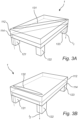
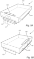
- an electrical current I3 is passed between the second electrode element 122 and the third electrode element 123, such that a third geometrical structure 133 is generated between the second and third electrode element 122, 123.
Landscapes
- Physics & Mathematics (AREA)
- General Physics & Mathematics (AREA)
- Nonlinear Science (AREA)
- Optics & Photonics (AREA)
- Optical Modulation, Optical Deflection, Nonlinear Optics, Optical Demodulation, Optical Logic Elements (AREA)
Claims (15)
- Optische Vorrichtung (1) zum Modulieren von einfallendem Licht (L), umfassend:eine resonanzdefinierende Schichtstruktur (110), die ein optisches Zustandsänderungsmaterial (112) umfasst;eine Elektrodenschicht (120), die mindestens zwei beabstandete Elektrodenelemente (121, 122, 123) umfasst;wobei die Elektrodenelemente individuell adressierbar sind und angeordnet sind, um eine optische Zustandsänderung eines Abschnitts des optischen Zustandsänderungsmaterials zwischen einem ersten Zustand und einem zweiten Zustand zu bewirken;wobei der Abschnitt eine geometrische Struktur (131, 132, 133, 134, 135, 136) bildet, die durch die Anordnung der mindestens zwei beabstandeten Elektrodenelemente definiert ist,wobei das optische Zustandsänderungsmaterial dazu konfiguriert ist, eine optische Reaktion der optischen Vorrichtung bei der optischen Zustandsänderung zwischen dem ersten Zustand und dem zweiten Zustand zu ändern, wobei die optische Reaktion die Modulation des einfallenden Lichts bestimmt.
- Optische Vorrichtung nach Anspruch 1, wobei das optische Zustandsänderungsmaterial ein Phasenänderungsmaterial ist, wobei das Phasenänderungsmaterial bevorzugt aus einer Zusammensetzung gebildet ist, die Germanium-Antimon-Tellur, GST, umfasst, und wobei eine optische Zustandsänderung eine Phasenänderung des Phasenänderungsmaterials ist.
- Optische Vorrichtung nach Anspruch 1 oder 2, wobei die Elektrodenelemente ferner dazu konfiguriert sind, wiederholt eine optische Zustandsänderung des Abschnitts des optischen Zustandsänderungsmaterials zwischen dem ersten und dem zweiten Zustand zu bewirken.
- Optische Vorrichtung nach einem der vorhergehenden Ansprüche, wobei die resonanzdefinierende Schichtstruktur ferner eine elektrisch leitende und/oder eine elektrisch isolierende Schicht (114) umfasst.
- Optische Vorrichtung nach einem der vorhergehenden Ansprüche, wobei die Elektrodenelemente dazu konfiguriert sind, einen Strom (I1, I2, I3) in mindestens einer Schicht der resonanzdefinierenden Schichtstruktur zu induzieren, um die optische Zustandsänderung des Abschnitts des optischen Zustandsänderungsmaterials zu bewirken.
- Optische Vorrichtung nach einem der vorhergehenden Ansprüche, umfassend mindestens drei Elektrodenelemente, die angeordnet sind, um mindestens zwei verschiedene geometrische Strukturen in dem optischen Zustandsänderungsmaterial zu definieren.
- Optische Vorrichtung nach Anspruch 6, wobei die mindestens zwei verschiedenen geometrischen Strukturen zusammen eine V-Form und/oder eine L-Form bilden, wenn sie in einer Richtung gesehen werden, die zur Oberfläche der resonanzdefinierenden Schichtstruktur rechtwinklig ist.
- Optische Vorrichtung nach einem der vorhergehenden Ansprüche, wobei die optische Vorrichtung dazu konfiguriert ist, einfallendes Licht mit einer Wellenlänge in dem Bereich von 100 nm bis 2000 nm, bevorzugt von 300 nm bis 750 nm, zu modulieren.
- Optische Vorrichtung nach einem der vorhergehenden Ansprüche, wobei die Vorrichtung dazu konfiguriert ist, polarisiertes Licht zu modulieren.
- Optische Vorrichtung nach einem der vorhergehenden Ansprüche, wobei das optische Zustandsänderungsmaterial in einer Schicht angeordnet ist, die eine Dicke aufweist, die kleiner als eine Mindestwellenlänge des zu modulierenden einfallenden Lichtes ist.
- Optische Vorrichtung nach einem der vorhergehenden Ansprüche, wobei der erste Zustand des optischen Zustandsänderungsmaterials ein dominant kristalliner Zustand ist, und wobei der zweite Zustand des optischen Zustandsänderungsmaterials ein dominant amorpher Zustand ist.
- Optische Vorrichtung nach einem der vorhergehenden Ansprüche, wobei die resonanzdefinierende Schichtstruktur und die Elektrodenschicht in einer Stapelstruktur angeordnet sind, und wobei die Elektrodenschicht über und/oder unter der resonanzdefinierenden Schichtstruktur angeordnet ist, wenn sie in einer Richtung gesehen werden, die zu der Oberfläche der resonanzdefinierenden Schichtstruktur rechtwinklig ist.
- Verfahren zum Modulieren von Licht, das auf eine optische Vorrichtung nach einem der vorhergehenden Ansprüche einfällt, umfassend folgende Schritte:Anwenden (10) einer ersten Spannungsdifferenz auf ein Paar der mindestens zwei Elektrodenelemente der optischen Vorrichtung, um eine optische Zustandsänderung des Abschnitts des optischen Zustandsänderungsmaterials von einem ersten Zustand in einen zweiten Zustand zu bewirken, undAnwenden (20) einer zweiten Spannungsdifferenz auf das Paar von Elektrodenelementen, um eine optische Zustandsänderung des optischen Zustandsänderungsmaterials von dem zweiten Zustand in den ersten Zustand zu bewirken.
- Verfahren nach Anspruch 13, wobei die zweite Spannungsdifferenz geringer als die erste Spannungsdifferenz ist und/oder während eines längeren Zeitraums als die erste Spannungsdifferenz angewendet wird.
- Verfahren nach Anspruch 13 oder Anspruch 14, wobei die Elektrodenschicht mindestens drei Elektrodenelemente umfasst, wobei das Verfahren ferner folgende Schritte umfasst:Anwenden (30) der ersten Spannungsdifferenz auf ein zweites Paar von Elektrodenelementen, um eine optische Zustandsänderung eines weiteren Abschnitts des optischen Zustandsänderungsmaterials von dem ersten Zustand in den zweiten Zustand zu bewirken, undAnwenden (40) der zweiten Spannungsdifferenz auf ein zweites Paar von Elektrodenelementen, um eine optische Zustandsänderung des weiteren Abschnitts des optischen Zustandsänderungsmaterials von dem ersten Zustand in den zweiten Zustand zu bewirken.
Priority Applications (4)
| Application Number | Priority Date | Filing Date | Title |
|---|---|---|---|
| EP19188130.9A EP3770672B1 (de) | 2019-07-24 | 2019-07-24 | Optische vorrichtung zur modulierung von einfallendem licht |
| CN202080051468.7A CN114127624B (zh) | 2019-07-24 | 2020-07-09 | 用于调制入射光的光学器件 |
| PCT/EP2020/069427 WO2021013572A1 (en) | 2019-07-24 | 2020-07-09 | An optical device for modulating incident light |
| US17/628,657 US12481180B2 (en) | 2019-07-24 | 2020-07-09 | Optical device for modulating incident light |
Applications Claiming Priority (1)
| Application Number | Priority Date | Filing Date | Title |
|---|---|---|---|
| EP19188130.9A EP3770672B1 (de) | 2019-07-24 | 2019-07-24 | Optische vorrichtung zur modulierung von einfallendem licht |
Publications (2)
| Publication Number | Publication Date |
|---|---|
| EP3770672A1 EP3770672A1 (de) | 2021-01-27 |
| EP3770672B1 true EP3770672B1 (de) | 2024-07-10 |
Family
ID=67438740
Family Applications (1)
| Application Number | Title | Priority Date | Filing Date |
|---|---|---|---|
| EP19188130.9A Active EP3770672B1 (de) | 2019-07-24 | 2019-07-24 | Optische vorrichtung zur modulierung von einfallendem licht |
Country Status (4)
| Country | Link |
|---|---|
| US (1) | US12481180B2 (de) |
| EP (1) | EP3770672B1 (de) |
| CN (1) | CN114127624B (de) |
| WO (1) | WO2021013572A1 (de) |
Family Cites Families (13)
| Publication number | Priority date | Publication date | Assignee | Title |
|---|---|---|---|---|
| IL106009A0 (en) * | 1993-06-14 | 1993-10-20 | Amir Alon | Method and apparatus for the simultaneous writing of data on an optical disk |
| GB2287327A (en) * | 1994-03-02 | 1995-09-13 | Sharp Kk | Electro-optic apparatus |
| US6690500B2 (en) * | 2000-06-30 | 2004-02-10 | Pioneer Corporation | Aberration correction apparatus and method |
| EP1647858A1 (de) * | 2004-10-18 | 2006-04-19 | Ecsibeo Ab | Cholseterisches Flüssigkristallanzeigesystem und Verfahren zur Herstellung |
| TWI400542B (zh) * | 2009-10-08 | 2013-07-01 | Chunghwa Picture Tubes Ltd | 半穿透半反射式薄膜電晶體面板及其製造方法 |
| US8971089B2 (en) * | 2012-06-27 | 2015-03-03 | Intel Corporation | Low power phase change memory cell |
| KR102176583B1 (ko) * | 2013-12-09 | 2020-11-09 | 삼성전자주식회사 | 홀로그래피 3차원 영상 표시 장치 및 방법 |
| KR102054041B1 (ko) * | 2013-12-23 | 2020-01-08 | 옥스포드 유니버시티 이노베이션 리미티드 | 상변화 물질에 기초한 디스플레이 장치 |
| EP3203309A1 (de) * | 2016-02-04 | 2017-08-09 | Bodle Technologies Limited | Optische vorrichtung mit thermisch umschaltendem phasenwechselmaterial |
| SG11201806553WA (en) * | 2016-02-05 | 2018-08-30 | Agency Science Tech & Res | Device and arrangement for controlling an electromagnetic wave, methods of forming and operating the same |
| KR102491605B1 (ko) * | 2017-12-27 | 2023-01-20 | 엘지디스플레이 주식회사 | 조명 장치 |
| EP3521912B1 (de) | 2018-01-31 | 2021-10-27 | IMEC vzw | Optische vorrichtung zur erzeugung der verteilung eines dreidimensionalen lichtfeldes |
| WO2020150110A1 (en) * | 2019-01-14 | 2020-07-23 | California Institute Of Technology | Electrically tunable metasurfaces incorporating a phase change material |
-
2019
- 2019-07-24 EP EP19188130.9A patent/EP3770672B1/de active Active
-
2020
- 2020-07-09 CN CN202080051468.7A patent/CN114127624B/zh active Active
- 2020-07-09 US US17/628,657 patent/US12481180B2/en active Active
- 2020-07-09 WO PCT/EP2020/069427 patent/WO2021013572A1/en not_active Ceased
Also Published As
| Publication number | Publication date |
|---|---|
| US12481180B2 (en) | 2025-11-25 |
| CN114127624B (zh) | 2025-06-24 |
| WO2021013572A1 (en) | 2021-01-28 |
| CN114127624A (zh) | 2022-03-01 |
| EP3770672A1 (de) | 2021-01-27 |
| US20220252909A1 (en) | 2022-08-11 |
Similar Documents
| Publication | Publication Date | Title |
|---|---|---|
| Jeong et al. | Dynamic terahertz plasmonics enabled by phase‐change materials | |
| Ding et al. | Electrically tunable optical metasurfaces | |
| US7561320B2 (en) | Modulation of electromagnetic radiation with electrically controllable composite material | |
| US10593873B2 (en) | Device for switchably influencing electromagnetic radiation, and method for obtaining such a device | |
| US20100165431A1 (en) | Dynamically reconfigurable holograms with electronically erasable programmable intermediate layers | |
| EP3254154B1 (de) | Optische modulationsvorrichtung mit gate-struktur | |
| US8797382B2 (en) | Dynamically reconfigurable holograms for generating color holographic images | |
| Vendik et al. | Tunable metamaterials for controlling THz radiation | |
| US20160223723A1 (en) | Optical modulating device having gate structure | |
| US8107149B2 (en) | Negative index material-based modulators and methods for fabricating the same | |
| CN108604637B (zh) | 控制电磁波的设备和装置及其形成和操作方法 | |
| US11506917B2 (en) | Optical device for forming a distribution of a three-dimensional light field | |
| US20110273755A1 (en) | Dynamically reconfigurable holograms | |
| EP3762760B1 (de) | Elektrisch rekonfigurierbare optische vorrichtung anhand eines elektrischen feldes | |
| CN111771168A (zh) | 用于形成三维光场分布的光学器件、系统和方法 | |
| EP3770672B1 (de) | Optische vorrichtung zur modulierung von einfallendem licht | |
| US20120154880A1 (en) | Optical modulators | |
| US20110273756A1 (en) | Dynamically reconfigurable holograms with chalcogenide intermediate layers | |
| CN114005932B (zh) | 一种基于相变材料的可控超表面结构及其制备方法 | |
| Khiavi | Theory and Design of Spatiotemporal Metasurfaces for Comprehensive Control of Light | |
| Miyazaki et al. | Enhanced light diffraction from a double-layer microsphere lattice | |
| US9104031B2 (en) | Active optical device and display apparatus including the same | |
| Yang et al. | Multifunctional metasurfaces: From versatile electromagnetic control to array antenna applications | |
| Wang | Electrically Reconfigurable Phase-Change Antennas and Metasurfaces | |
| Mun et al. | Wavelength-selective beam deflector based on Fano-resonant metasurface |
Legal Events
| Date | Code | Title | Description |
|---|---|---|---|
| PUAI | Public reference made under article 153(3) epc to a published international application that has entered the european phase |
Free format text: ORIGINAL CODE: 0009012 |
|
| STAA | Information on the status of an ep patent application or granted ep patent |
Free format text: STATUS: THE APPLICATION HAS BEEN PUBLISHED |
|
| AK | Designated contracting states |
Kind code of ref document: A1 Designated state(s): AL AT BE BG CH CY CZ DE DK EE ES FI FR GB GR HR HU IE IS IT LI LT LU LV MC MK MT NL NO PL PT RO RS SE SI SK SM TR |
|
| AX | Request for extension of the european patent |
Extension state: BA ME |
|
| STAA | Information on the status of an ep patent application or granted ep patent |
Free format text: STATUS: REQUEST FOR EXAMINATION WAS MADE |
|
| 17P | Request for examination filed |
Effective date: 20210624 |
|
| RBV | Designated contracting states (corrected) |
Designated state(s): AL AT BE BG CH CY CZ DE DK EE ES FI FR GB GR HR HU IE IS IT LI LT LU LV MC MK MT NL NO PL PT RO RS SE SI SK SM TR |
|
| STAA | Information on the status of an ep patent application or granted ep patent |
Free format text: STATUS: EXAMINATION IS IN PROGRESS |
|
| 17Q | First examination report despatched |
Effective date: 20220706 |
|
| GRAP | Despatch of communication of intention to grant a patent |
Free format text: ORIGINAL CODE: EPIDOSNIGR1 |
|
| STAA | Information on the status of an ep patent application or granted ep patent |
Free format text: STATUS: GRANT OF PATENT IS INTENDED |
|
| INTG | Intention to grant announced |
Effective date: 20240206 |
|
| P01 | Opt-out of the competence of the unified patent court (upc) registered |
Effective date: 20240328 |
|
| GRAS | Grant fee paid |
Free format text: ORIGINAL CODE: EPIDOSNIGR3 |
|
| GRAA | (expected) grant |
Free format text: ORIGINAL CODE: 0009210 |
|
| STAA | Information on the status of an ep patent application or granted ep patent |
Free format text: STATUS: THE PATENT HAS BEEN GRANTED |
|
| AK | Designated contracting states |
Kind code of ref document: B1 Designated state(s): AL AT BE BG CH CY CZ DE DK EE ES FI FR GB GR HR HU IE IS IT LI LT LU LV MC MK MT NL NO PL PT RO RS SE SI SK SM TR |
|
| REG | Reference to a national code |
Ref country code: CH Ref legal event code: EP |
|
| REG | Reference to a national code |
Ref country code: DE Ref legal event code: R096 Ref document number: 602019054888 Country of ref document: DE |
|
| REG | Reference to a national code |
Ref country code: LT Ref legal event code: MG9D |
|
| REG | Reference to a national code |
Ref country code: NL Ref legal event code: MP Effective date: 20240710 |
|
| PG25 | Lapsed in a contracting state [announced via postgrant information from national office to epo] |
Ref country code: PT Free format text: LAPSE BECAUSE OF FAILURE TO SUBMIT A TRANSLATION OF THE DESCRIPTION OR TO PAY THE FEE WITHIN THE PRESCRIBED TIME-LIMIT Effective date: 20241111 |
|
| REG | Reference to a national code |
Ref country code: AT Ref legal event code: MK05 Ref document number: 1702562 Country of ref document: AT Kind code of ref document: T Effective date: 20240710 |
|
| PG25 | Lapsed in a contracting state [announced via postgrant information from national office to epo] |
Ref country code: NL Free format text: LAPSE BECAUSE OF FAILURE TO SUBMIT A TRANSLATION OF THE DESCRIPTION OR TO PAY THE FEE WITHIN THE PRESCRIBED TIME-LIMIT Effective date: 20240710 |
|
| PG25 | Lapsed in a contracting state [announced via postgrant information from national office to epo] |
Ref country code: PT Free format text: LAPSE BECAUSE OF FAILURE TO SUBMIT A TRANSLATION OF THE DESCRIPTION OR TO PAY THE FEE WITHIN THE PRESCRIBED TIME-LIMIT Effective date: 20241111 Ref country code: NL Free format text: LAPSE BECAUSE OF FAILURE TO SUBMIT A TRANSLATION OF THE DESCRIPTION OR TO PAY THE FEE WITHIN THE PRESCRIBED TIME-LIMIT Effective date: 20240710 |
|
| PG25 | Lapsed in a contracting state [announced via postgrant information from national office to epo] |
Ref country code: NO Free format text: LAPSE BECAUSE OF FAILURE TO SUBMIT A TRANSLATION OF THE DESCRIPTION OR TO PAY THE FEE WITHIN THE PRESCRIBED TIME-LIMIT Effective date: 20241010 |
|
| PG25 | Lapsed in a contracting state [announced via postgrant information from national office to epo] |
Ref country code: FI Free format text: LAPSE BECAUSE OF FAILURE TO SUBMIT A TRANSLATION OF THE DESCRIPTION OR TO PAY THE FEE WITHIN THE PRESCRIBED TIME-LIMIT Effective date: 20240710 Ref country code: PL Free format text: LAPSE BECAUSE OF FAILURE TO SUBMIT A TRANSLATION OF THE DESCRIPTION OR TO PAY THE FEE WITHIN THE PRESCRIBED TIME-LIMIT Effective date: 20240710 Ref country code: GR Free format text: LAPSE BECAUSE OF FAILURE TO SUBMIT A TRANSLATION OF THE DESCRIPTION OR TO PAY THE FEE WITHIN THE PRESCRIBED TIME-LIMIT Effective date: 20241011 |
|
| PG25 | Lapsed in a contracting state [announced via postgrant information from national office to epo] |
Ref country code: BG Free format text: LAPSE BECAUSE OF FAILURE TO SUBMIT A TRANSLATION OF THE DESCRIPTION OR TO PAY THE FEE WITHIN THE PRESCRIBED TIME-LIMIT Effective date: 20240710 |
|
| PG25 | Lapsed in a contracting state [announced via postgrant information from national office to epo] |
Ref country code: LV Free format text: LAPSE BECAUSE OF FAILURE TO SUBMIT A TRANSLATION OF THE DESCRIPTION OR TO PAY THE FEE WITHIN THE PRESCRIBED TIME-LIMIT Effective date: 20240710 |
|
| PG25 | Lapsed in a contracting state [announced via postgrant information from national office to epo] |
Ref country code: IS Free format text: LAPSE BECAUSE OF FAILURE TO SUBMIT A TRANSLATION OF THE DESCRIPTION OR TO PAY THE FEE WITHIN THE PRESCRIBED TIME-LIMIT Effective date: 20241110 Ref country code: AT Free format text: LAPSE BECAUSE OF FAILURE TO SUBMIT A TRANSLATION OF THE DESCRIPTION OR TO PAY THE FEE WITHIN THE PRESCRIBED TIME-LIMIT Effective date: 20240710 |
|
| PG25 | Lapsed in a contracting state [announced via postgrant information from national office to epo] |
Ref country code: HR Free format text: LAPSE BECAUSE OF FAILURE TO SUBMIT A TRANSLATION OF THE DESCRIPTION OR TO PAY THE FEE WITHIN THE PRESCRIBED TIME-LIMIT Effective date: 20240710 |
|
| PG25 | Lapsed in a contracting state [announced via postgrant information from national office to epo] |
Ref country code: RS Free format text: LAPSE BECAUSE OF FAILURE TO SUBMIT A TRANSLATION OF THE DESCRIPTION OR TO PAY THE FEE WITHIN THE PRESCRIBED TIME-LIMIT Effective date: 20241010 Ref country code: ES Free format text: LAPSE BECAUSE OF FAILURE TO SUBMIT A TRANSLATION OF THE DESCRIPTION OR TO PAY THE FEE WITHIN THE PRESCRIBED TIME-LIMIT Effective date: 20240710 |
|
| PG25 | Lapsed in a contracting state [announced via postgrant information from national office to epo] |
Ref country code: RS Free format text: LAPSE BECAUSE OF FAILURE TO SUBMIT A TRANSLATION OF THE DESCRIPTION OR TO PAY THE FEE WITHIN THE PRESCRIBED TIME-LIMIT Effective date: 20241010 Ref country code: PL Free format text: LAPSE BECAUSE OF FAILURE TO SUBMIT A TRANSLATION OF THE DESCRIPTION OR TO PAY THE FEE WITHIN THE PRESCRIBED TIME-LIMIT Effective date: 20240710 Ref country code: NO Free format text: LAPSE BECAUSE OF FAILURE TO SUBMIT A TRANSLATION OF THE DESCRIPTION OR TO PAY THE FEE WITHIN THE PRESCRIBED TIME-LIMIT Effective date: 20241010 Ref country code: LV Free format text: LAPSE BECAUSE OF FAILURE TO SUBMIT A TRANSLATION OF THE DESCRIPTION OR TO PAY THE FEE WITHIN THE PRESCRIBED TIME-LIMIT Effective date: 20240710 Ref country code: IS Free format text: LAPSE BECAUSE OF FAILURE TO SUBMIT A TRANSLATION OF THE DESCRIPTION OR TO PAY THE FEE WITHIN THE PRESCRIBED TIME-LIMIT Effective date: 20241110 Ref country code: HR Free format text: LAPSE BECAUSE OF FAILURE TO SUBMIT A TRANSLATION OF THE DESCRIPTION OR TO PAY THE FEE WITHIN THE PRESCRIBED TIME-LIMIT Effective date: 20240710 Ref country code: GR Free format text: LAPSE BECAUSE OF FAILURE TO SUBMIT A TRANSLATION OF THE DESCRIPTION OR TO PAY THE FEE WITHIN THE PRESCRIBED TIME-LIMIT Effective date: 20241011 Ref country code: FI Free format text: LAPSE BECAUSE OF FAILURE TO SUBMIT A TRANSLATION OF THE DESCRIPTION OR TO PAY THE FEE WITHIN THE PRESCRIBED TIME-LIMIT Effective date: 20240710 Ref country code: ES Free format text: LAPSE BECAUSE OF FAILURE TO SUBMIT A TRANSLATION OF THE DESCRIPTION OR TO PAY THE FEE WITHIN THE PRESCRIBED TIME-LIMIT Effective date: 20240710 Ref country code: BG Free format text: LAPSE BECAUSE OF FAILURE TO SUBMIT A TRANSLATION OF THE DESCRIPTION OR TO PAY THE FEE WITHIN THE PRESCRIBED TIME-LIMIT Effective date: 20240710 Ref country code: AT Free format text: LAPSE BECAUSE OF FAILURE TO SUBMIT A TRANSLATION OF THE DESCRIPTION OR TO PAY THE FEE WITHIN THE PRESCRIBED TIME-LIMIT Effective date: 20240710 |
|
| REG | Reference to a national code |
Ref country code: CH Ref legal event code: PL |
|
| PG25 | Lapsed in a contracting state [announced via postgrant information from national office to epo] |
Ref country code: LU Free format text: LAPSE BECAUSE OF NON-PAYMENT OF DUE FEES Effective date: 20240724 |
|
| PG25 | Lapsed in a contracting state [announced via postgrant information from national office to epo] |
Ref country code: LU Free format text: LAPSE BECAUSE OF NON-PAYMENT OF DUE FEES Effective date: 20240724 |
|
| REG | Reference to a national code |
Ref country code: DE Ref legal event code: R097 Ref document number: 602019054888 Country of ref document: DE |
|
| PG25 | Lapsed in a contracting state [announced via postgrant information from national office to epo] |
Ref country code: DK Free format text: LAPSE BECAUSE OF FAILURE TO SUBMIT A TRANSLATION OF THE DESCRIPTION OR TO PAY THE FEE WITHIN THE PRESCRIBED TIME-LIMIT Effective date: 20240710 Ref country code: RO Free format text: LAPSE BECAUSE OF FAILURE TO SUBMIT A TRANSLATION OF THE DESCRIPTION OR TO PAY THE FEE WITHIN THE PRESCRIBED TIME-LIMIT Effective date: 20240710 Ref country code: SM Free format text: LAPSE BECAUSE OF FAILURE TO SUBMIT A TRANSLATION OF THE DESCRIPTION OR TO PAY THE FEE WITHIN THE PRESCRIBED TIME-LIMIT Effective date: 20240710 |
|
| PG25 | Lapsed in a contracting state [announced via postgrant information from national office to epo] |
Ref country code: MC Free format text: LAPSE BECAUSE OF FAILURE TO SUBMIT A TRANSLATION OF THE DESCRIPTION OR TO PAY THE FEE WITHIN THE PRESCRIBED TIME-LIMIT Effective date: 20240710 Ref country code: BE Free format text: LAPSE BECAUSE OF NON-PAYMENT OF DUE FEES Effective date: 20240731 Ref country code: CH Free format text: LAPSE BECAUSE OF NON-PAYMENT OF DUE FEES Effective date: 20240731 Ref country code: EE Free format text: LAPSE BECAUSE OF FAILURE TO SUBMIT A TRANSLATION OF THE DESCRIPTION OR TO PAY THE FEE WITHIN THE PRESCRIBED TIME-LIMIT Effective date: 20240710 |
|
| PG25 | Lapsed in a contracting state [announced via postgrant information from national office to epo] |
Ref country code: CZ Free format text: LAPSE BECAUSE OF FAILURE TO SUBMIT A TRANSLATION OF THE DESCRIPTION OR TO PAY THE FEE WITHIN THE PRESCRIBED TIME-LIMIT Effective date: 20240710 |
|
| PG25 | Lapsed in a contracting state [announced via postgrant information from national office to epo] |
Ref country code: IT Free format text: LAPSE BECAUSE OF FAILURE TO SUBMIT A TRANSLATION OF THE DESCRIPTION OR TO PAY THE FEE WITHIN THE PRESCRIBED TIME-LIMIT Effective date: 20240710 Ref country code: SK Free format text: LAPSE BECAUSE OF FAILURE TO SUBMIT A TRANSLATION OF THE DESCRIPTION OR TO PAY THE FEE WITHIN THE PRESCRIBED TIME-LIMIT Effective date: 20240710 |
|
| REG | Reference to a national code |
Ref country code: DE Ref legal event code: R081 Ref document number: 602019054888 Country of ref document: DE Owner name: SWAVE BV, BE Free format text: FORMER OWNERS: IMEC VZW, LEUVEN, BE; KATHOLIEKE UNIVERSITEIT LEUVEN KU LEUVEN RESEARCH & DEVELOPMENT, LEUVEN, BE Ref country code: DE Ref legal event code: R081 Ref document number: 602019054888 Country of ref document: DE Owner name: KATHOLIEKE UNIVERSITEIT LEUVEN KU LEUVEN RESEA, BE Free format text: FORMER OWNERS: IMEC VZW, LEUVEN, BE; KATHOLIEKE UNIVERSITEIT LEUVEN KU LEUVEN RESEARCH & DEVELOPMENT, LEUVEN, BE |
|
| PLBE | No opposition filed within time limit |
Free format text: ORIGINAL CODE: 0009261 |
|
| STAA | Information on the status of an ep patent application or granted ep patent |
Free format text: STATUS: NO OPPOSITION FILED WITHIN TIME LIMIT |
|
| REG | Reference to a national code |
Ref country code: BE Ref legal event code: MM Effective date: 20240731 |
|
| 26N | No opposition filed |
Effective date: 20250411 |
|
| GBPC | Gb: european patent ceased through non-payment of renewal fee |
Effective date: 20241010 |
|
| PG25 | Lapsed in a contracting state [announced via postgrant information from national office to epo] |
Ref country code: GB Free format text: LAPSE BECAUSE OF NON-PAYMENT OF DUE FEES Effective date: 20241010 |
|
| PG25 | Lapsed in a contracting state [announced via postgrant information from national office to epo] |
Ref country code: FR Free format text: LAPSE BECAUSE OF NON-PAYMENT OF DUE FEES Effective date: 20240910 |
|
| PG25 | Lapsed in a contracting state [announced via postgrant information from national office to epo] |
Ref country code: IE Free format text: LAPSE BECAUSE OF NON-PAYMENT OF DUE FEES Effective date: 20240724 |
|
| PG25 | Lapsed in a contracting state [announced via postgrant information from national office to epo] |
Ref country code: SE Free format text: LAPSE BECAUSE OF FAILURE TO SUBMIT A TRANSLATION OF THE DESCRIPTION OR TO PAY THE FEE WITHIN THE PRESCRIBED TIME-LIMIT Effective date: 20240710 |
|
| PGFP | Annual fee paid to national office [announced via postgrant information from national office to epo] |
Ref country code: DE Payment date: 20250728 Year of fee payment: 7 |
|
| PG25 | Lapsed in a contracting state [announced via postgrant information from national office to epo] |
Ref country code: CY Free format text: LAPSE BECAUSE OF FAILURE TO SUBMIT A TRANSLATION OF THE DESCRIPTION OR TO PAY THE FEE WITHIN THE PRESCRIBED TIME-LIMIT; INVALID AB INITIO Effective date: 20190724 |
|
| PG25 | Lapsed in a contracting state [announced via postgrant information from national office to epo] |
Ref country code: HU Free format text: LAPSE BECAUSE OF FAILURE TO SUBMIT A TRANSLATION OF THE DESCRIPTION OR TO PAY THE FEE WITHIN THE PRESCRIBED TIME-LIMIT; INVALID AB INITIO Effective date: 20190724 |