EP3770503A1 - Fluid distributor passages - Google Patents
Fluid distributor passages Download PDFInfo
- Publication number
- EP3770503A1 EP3770503A1 EP19214670.2A EP19214670A EP3770503A1 EP 3770503 A1 EP3770503 A1 EP 3770503A1 EP 19214670 A EP19214670 A EP 19214670A EP 3770503 A1 EP3770503 A1 EP 3770503A1
- Authority
- EP
- European Patent Office
- Prior art keywords
- swirl
- passages
- fluid distributor
- distributor
- ceiling
- Prior art date
- Legal status (The legal status is an assumption and is not a legal conclusion. Google has not performed a legal analysis and makes no representation as to the accuracy of the status listed.)
- Granted
Links
Images




Classifications
-
- F—MECHANICAL ENGINEERING; LIGHTING; HEATING; WEAPONS; BLASTING
- F23—COMBUSTION APPARATUS; COMBUSTION PROCESSES
- F23R—GENERATING COMBUSTION PRODUCTS OF HIGH PRESSURE OR HIGH VELOCITY, e.g. GAS-TURBINE COMBUSTION CHAMBERS
- F23R3/00—Continuous combustion chambers using liquid or gaseous fuel
- F23R3/28—Continuous combustion chambers using liquid or gaseous fuel characterised by the fuel supply
- F23R3/283—Attaching or cooling of fuel injecting means including supports for fuel injectors, stems, or lances
-
- B—PERFORMING OPERATIONS; TRANSPORTING
- B05—SPRAYING OR ATOMISING IN GENERAL; APPLYING FLUENT MATERIALS TO SURFACES, IN GENERAL
- B05B—SPRAYING APPARATUS; ATOMISING APPARATUS; NOZZLES
- B05B1/00—Nozzles, spray heads or other outlets, with or without auxiliary devices such as valves, heating means
- B05B1/34—Nozzles, spray heads or other outlets, with or without auxiliary devices such as valves, heating means designed to influence the nature of flow of the liquid or other fluent material, e.g. to produce swirl
- B05B1/3405—Nozzles, spray heads or other outlets, with or without auxiliary devices such as valves, heating means designed to influence the nature of flow of the liquid or other fluent material, e.g. to produce swirl to produce swirl
- B05B1/341—Nozzles, spray heads or other outlets, with or without auxiliary devices such as valves, heating means designed to influence the nature of flow of the liquid or other fluent material, e.g. to produce swirl to produce swirl before discharging the liquid or other fluent material, e.g. in a swirl chamber upstream the spray outlet
-
- F—MECHANICAL ENGINEERING; LIGHTING; HEATING; WEAPONS; BLASTING
- F23—COMBUSTION APPARATUS; COMBUSTION PROCESSES
- F23D—BURNERS
- F23D11/00—Burners using a direct spraying action of liquid droplets or vaporised liquid into the combustion space
- F23D11/36—Details
- F23D11/38—Nozzles; Cleaning devices therefor
- F23D11/383—Nozzles; Cleaning devices therefor with swirl means
-
- F—MECHANICAL ENGINEERING; LIGHTING; HEATING; WEAPONS; BLASTING
- F23—COMBUSTION APPARATUS; COMBUSTION PROCESSES
- F23R—GENERATING COMBUSTION PRODUCTS OF HIGH PRESSURE OR HIGH VELOCITY, e.g. GAS-TURBINE COMBUSTION CHAMBERS
- F23R3/00—Continuous combustion chambers using liquid or gaseous fuel
- F23R3/28—Continuous combustion chambers using liquid or gaseous fuel characterised by the fuel supply
- F23R3/36—Supply of different fuels
-
- F—MECHANICAL ENGINEERING; LIGHTING; HEATING; WEAPONS; BLASTING
- F23—COMBUSTION APPARATUS; COMBUSTION PROCESSES
- F23R—GENERATING COMBUSTION PRODUCTS OF HIGH PRESSURE OR HIGH VELOCITY, e.g. GAS-TURBINE COMBUSTION CHAMBERS
- F23R2900/00—Special features of, or arrangements for continuous combustion chambers; Combustion processes therefor
- F23R2900/00018—Manufacturing combustion chamber liners or subparts
-
- Y—GENERAL TAGGING OF NEW TECHNOLOGICAL DEVELOPMENTS; GENERAL TAGGING OF CROSS-SECTIONAL TECHNOLOGIES SPANNING OVER SEVERAL SECTIONS OF THE IPC; TECHNICAL SUBJECTS COVERED BY FORMER USPC CROSS-REFERENCE ART COLLECTIONS [XRACs] AND DIGESTS
- Y02—TECHNOLOGIES OR APPLICATIONS FOR MITIGATION OR ADAPTATION AGAINST CLIMATE CHANGE
- Y02P—CLIMATE CHANGE MITIGATION TECHNOLOGIES IN THE PRODUCTION OR PROCESSING OF GOODS
- Y02P10/00—Technologies related to metal processing
- Y02P10/25—Process efficiency
Definitions
- the present disclosure relates to fluid distributors, and in particular to fluid distributors for fuel manifolds and injection nozzles for gas turbine engines.
- injectors such as gas turbine engine fuel injectors
- additive manufacturing processes to the production of injectors.
- additive manufacturing processes have limitations that designers must avoid exceeding.
- One example is that conventional additive manufacturing techniques limit how great a swirl angle can be imposed in an additively manufactured injector.
- a fluid distributor passage is produced by a process of additively manufacturing a floor, ceiling, and opposed sidewalls of the fluid distributor passage using a build direction. At least one of the floor and/or the ceiling define a swirl angle greater than 60 degrees relative to the build direction.
- a method includes additively manufacturing a fluid distributor passage along a build direction.
- the fluid distributor passage winds along a swirl path around a swirl axis that is aligned with the build direction.
- the swirl path is angled at a swirl angle greater than 60 degrees relative to the build direction.
- the swirl angle can be greater than 80 degrees relative to the build direction.
- the swirl angle can be greater than 88 degrees relative to the build direction.
- a ceiling of the swirl path can be self-supported without removable support structure during additively manufacturing the swirl path.
- a fluid distributor includes a distributor body defining a plurality of fluid distributor passages therethrough.
- Each of the fluid distributor passages winds in swirl direction about a swirl axis.
- the swirl direction defines a swirl angle of at least 60 degrees relative to the swirl axis.
- Each of the fluid distributor passages defines a floor and opposed ceiling, and an opposed pair of sidewalls. At least one of the floor and/or the ceiling is vaulted to define a surface that is angled less than 60 degrees relative to the swirl axis.
- Both of the ceiling and floor can be vaulted in the same direction, wherein the distributor passage has a chevron cross-sectional shape in radial cross-section relative to the swirl axis. Both of the ceiling and floor can be vaulted but in opposite directions.
- the fluid distributor passages can be in fluid communication to feed a pressure atomizer.
- the distributor passages can be in fluid communication with an annular outlet within an air blast atomizer.
- the air blast atomizer can include one or both of an inner air passage radially inboard of the distributor passages, and/or an outer air passage radially outboard of the distributor passages.
- the distributor passages can be liquid fuel passages and a plurality of gaseous fuel distributor passages can be included, each of the gaseous fuel distributor passages winding in a gas swirl direction about the swirl axis, wherein the gas swirl direction defines a gas swirl angle of at least 60 degrees relative to the swirl axis, each of the gaseous fuel distributor passages defining a floor and opposed ceiling, and an opposed pair of sidewalls, wherein at least one of the floor and/or the ceiling is vaulted to define a surface that is angled less than 60 degrees relative to the swirl axis.
- the gaseous fuel distributor passages can be radially inboard of the liquid fuel passages.
- the liquid fuel passages and gaseous fuel distributor passages can all feed into a single annular outlet orifice.
- the swirl angle can be 90 degrees relative to the swirl axis.
- the fluid distributor passages can define a conical profile.
- the ceiling can be vaulted from each sidewall. It is also contemplated that the ceiling can be vaulted from only one sidewall.
- the ceiling can be curved.
- FIG. 1 a partial view of an embodiment of a system in accordance with the disclosure is shown in Fig. 1 and is designated generally by reference character 100.
- FIGs. 2-17 Other embodiments of systems in accordance with the disclosure, or aspects thereof, are provided in Figs. 2-17 , as will be described to facilitate production of fluid distributors such as fuel injectors using additive manufacturing techniques.
- the fluid distributor 100 e.g., for use as a fuel injector for a gas turbine engine or the like, includes a distributor body 102 defining a liquid inlet 104 and a liquid outlet 106, which in Fig. 1 is in the form of an annular outlet orifice.
- An air inlet 108 and air outlet 110 are included for atomizing air flow used to atomize a spray of liquid from the liquid outlet 106, and a separate air swirler (not shown) can be nested within the fuel swirler of the distributor body 102.
- the distributor body 102 defines a plurality of fluid distributor passages 112 winding therethrough.
- the passages 112 are defined between an inner sidewall 114 and an outer sidewall 116.
- the outer sidewall 116 is shown removed from view so the winding of the passages 112 can be seen.
- Each of the fluid distributor passages 112 winds in swirl direction S (indicated in Fig. 1 ) about a swirl axis A, and the swirl direction defines a swirl angle ⁇ of at least 60 degrees relative to the swirl axis A.
- the angle ⁇ is the bulk angle, e.g. along which fluid would travel in one of the passages 112, taken at any position in one of the passages 112.
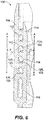
- the two flow arrows in Fig. 5 indicate the entrance of liquid through the liquid inlet 104, and the passage of liquid from an entrance plenum 118 into one of the passages 112.
- Each passage 112 has a passage outlet 120 that feeds in fluid communication into the annular chamber of the liquid outlet 106 (labeled in Figs. 1-2 ).
- the fluid distributor 100 can be part of an air blast atomizer that includes one or both of an inner air passage 110 radially inboard of the distributor passages 112, and/or an outer air passage 132 radially outboard of the distributor passages 112 (as indicated by the reference characters in Fig. 1 ).
- Figs. 3-4 show three surfaces 1, 2, and 3 in perspective and in side elevation, respectively.
- the surfaces 1, 2, and 3 are angled relative to the axis Z by angles ⁇ , ⁇ , and ⁇ .
- Those skilled in the art will readily appreciate that all surfaces, even curved surfaces, have a local angle relative to the z-axis.
- the local angle of the surfaces of the flow passages 112 in Fig. 5 is different from the bulk swirl angle ⁇ of the passage itself. This allows swirl angle ⁇ to be greater than 80 degrees relative to the build direction (indicated in Fig. 2 relative to the build plate 133).
- this can allow for swirl angles ⁇ greater than 88 degrees relative to the build direction, e.g. allowing the ceiling 123 (described below) of a fluid distributor passage 112 to be self-supporting during the build with good surface quality.
- the floor 125 and ceiling 123 are named according to their relative position with respect to the direction of gravity during a build, e.g., wherein the build direction is aligned with the direction of gravity, however after a build is complete, the floor 125 is not required to remain below the ceiling 123, since the completed build can be oriented as needed.
- each of the fluid distributor passages defines a ceiling 123 including two surfaces 122 and 124 and an opposed floor 125 including two surfaces 126 and 128, wherein the ceiling 123 and floor 125 are disposed between the opposed pair of sidewalls 116, 114.
- Each of ceilings 123 is vaulted into the two constituent surfaces 122, 124 to define a local surface that is angled locally at an angle ⁇ that is less than 60 degrees relative to the swirl axis A (those skilled in the art will readily appreciate that the swirl axis A is moved off center and shown in two different positions in Fig. 6 for convenience of labeling the angle ⁇ for two different ceiling surfaces 122 and 124).
- Both of the ceiling 123 and floor 125 are vaulted in the same direction, wherein the distributor passages 112 each has a chevron cross-sectional shape in radial cross-section relative to the swirl axis A.
- a fluid distributor 200 is shown having fluid distributor passages 216 that are in fluid communication to feed a pressure atomizer 211.
- the negative space of the fluid distributor passages 216 and pressure atomizer 211 are shown as solid forms for sake of clarity.
- cross-section in Fig. 8 in the passages 216 both of the ceiling 223 and floor 225 are vaulted but in opposite directions, so the passages 216 have a diamond cross-sectional shape relative to the axis A.
- a fluid distributor 300 is shown having fluid distributor passages 312, 317 that all feed into a single annular outlet orifice 306.
- the fluid distributor passages 317 are shown with the outer sidewall 316 removed for sake of clarity.
- the distributor passages 312 are liquid fuel passages, and are configured with the same chevron cross-sectional shape as passages 112 described above.
- the distributor passages 317 are a plurality of gaseous fuel distributor passages. Each of the gaseous fuel distributor passages 317 winds in a gas swirl direction about the swirl axis A, wherein the gas swirl direction defines a gas swirl angle ⁇ (identified in Fig. 10 ) of at least 60 degrees relative to the swirl axis A.
- each of the gaseous fuel distributor passages 317 defines a floor and opposed ceiling, and an opposed pair of sidewalls, wherein at least one of the floor and/or the ceiling is vaulted to define a surface that is angled less than 60 degrees relative to the swirl axis.
- the gaseous fuel distributor passages 317 are radially inboard of the liquid fuel passages 312. This configuration allows for dual fuel operation where liquid and/or gaseous fuel can be injected from the single annular outlet orifice 306.
- FIGs. 11 and 12 another fluid distributor 400 is shown, wherein the swirl angle ⁇ is fully 90 degrees relative to the swirl axis A, wherein the fluid distributor passages 412 spiral inward in a common plane P to outlets 410.
- the fluid distributor passages 512 of the fluid distributor 500 define a conical profile relative to the swirl axis A.
- the ceilings 423, 523 are each vaulted from each respective sidewall, but the floors 425, 525 are not vaulted.
- each distributor passage 612 has a ceiling 623 and floor 625 that vaulted from only one sidewall, i.e.
- the ceiling and or floor of the distributor passages 712 it is possible for the ceiling and or floor of the distributor passages 712 to be curved, i.e., the vaulting of the ceiling and optionally the floor follows a curve, e.g., for an egg shaped cross-sectional shape of the passages 712.
- the vaulting of the ceiling and optionally floors in the fluid distributor passages allows for the local angle ⁇ to not exceed the limits of a given additive manufacturing process, will allowing swirl angles ⁇ that exceed that limit.
- a method includes additively manufacturing a fluid distributor passage, e.g. passages 112, along a build direction, e.g., build direction indicated by the arrow in Fig. 2 .
- the fluid distributor passage winds along a swirl path around a swirl axis, e.g., swirl axis A that is aligned with the build direction.
- the swirl path is angled at a swirl angle, e.g., swirl angle ⁇ greater than 60 degrees relative to the build direction.
- the fluid distributor passage can be produced by a process of additively manufacturing a floor (e.g. floor 125), ceiling (e.g. ceiling 123), and opposed sidewalls (e.g. sidewalls 114, 116) of the fluid distributor passage using a build direction.
- At least one of the floor and/or the ceiling define a swirl angle greater than 60 degrees relative to the build direction.
- the ceiling of the swirl path can be self-supported without removable support structure during additively manufacturing the swirl path. While shown and described as used for fuel passages, those skilled in the art will readily appreciate that passages as disclosed herein can be used for air passages as well. For example, in Fig. 9 , the passages 317 could be used as an air swirler.
Landscapes
- Engineering & Computer Science (AREA)
- Chemical & Material Sciences (AREA)
- Combustion & Propulsion (AREA)
- Mechanical Engineering (AREA)
- General Engineering & Computer Science (AREA)
- Nozzles (AREA)
- Spray-Type Burners (AREA)
Abstract
Description
- The present disclosure relates to fluid distributors, and in particular to fluid distributors for fuel manifolds and injection nozzles for gas turbine engines.
- In injectors such as gas turbine engine fuel injectors, it is often desirable to have a high swirl angle where fluid exits the injector. It is also advantageous to employ additive manufacturing processes to the production of injectors. However, additive manufacturing processes have limitations that designers must avoid exceeding. One example is that conventional additive manufacturing techniques limit how great a swirl angle can be imposed in an additively manufactured injector.
- The conventional techniques have been considered satisfactory for their intended purpose. However, there is an ever present need for improved systems and methods for fluid distributor passages such as in injectors. This disclosure provides a solution for this need.
- A fluid distributor passage is produced by a process of additively manufacturing a floor, ceiling, and opposed sidewalls of the fluid distributor passage using a build direction. At least one of the floor and/or the ceiling define a swirl angle greater than 60 degrees relative to the build direction.
- A method includes additively manufacturing a fluid distributor passage along a build direction. The fluid distributor passage winds along a swirl path around a swirl axis that is aligned with the build direction. The swirl path is angled at a swirl angle greater than 60 degrees relative to the build direction.
- The swirl angle can be greater than 80 degrees relative to the build direction. The swirl angle can be greater than 88 degrees relative to the build direction. A ceiling of the swirl path can be self-supported without removable support structure during additively manufacturing the swirl path.
- A fluid distributor includes a distributor body defining a plurality of fluid distributor passages therethrough. Each of the fluid distributor passages winds in swirl direction about a swirl axis. The swirl direction defines a swirl angle of at least 60 degrees relative to the swirl axis. Each of the fluid distributor passages defines a floor and opposed ceiling, and an opposed pair of sidewalls. At least one of the floor and/or the ceiling is vaulted to define a surface that is angled less than 60 degrees relative to the swirl axis.
- Both of the ceiling and floor can be vaulted in the same direction, wherein the distributor passage has a chevron cross-sectional shape in radial cross-section relative to the swirl axis. Both of the ceiling and floor can be vaulted but in opposite directions.
- The fluid distributor passages can be in fluid communication to feed a pressure atomizer. The distributor passages can be in fluid communication with an annular outlet within an air blast atomizer. The air blast atomizer can include one or both of an inner air passage radially inboard of the distributor passages, and/or an outer air passage radially outboard of the distributor passages. The distributor passages can be liquid fuel passages and a plurality of gaseous fuel distributor passages can be included, each of the gaseous fuel distributor passages winding in a gas swirl direction about the swirl axis, wherein the gas swirl direction defines a gas swirl angle of at least 60 degrees relative to the swirl axis, each of the gaseous fuel distributor passages defining a floor and opposed ceiling, and an opposed pair of sidewalls, wherein at least one of the floor and/or the ceiling is vaulted to define a surface that is angled less than 60 degrees relative to the swirl axis. The gaseous fuel distributor passages can be radially inboard of the liquid fuel passages. The liquid fuel passages and gaseous fuel distributor passages can all feed into a single annular outlet orifice.
- The swirl angle can be 90 degrees relative to the swirl axis. The fluid distributor passages can define a conical profile. The ceiling can be vaulted from each sidewall. It is also contemplated that the ceiling can be vaulted from only one sidewall. The ceiling can be curved.
- These and other features of the systems and methods of the subject disclosure will become more readily apparent to those skilled in the art from the following detailed description of the preferred embodiments taken in conjunction with the drawings.
- So that those skilled in the art to which the subject disclosure appertains will readily understand how to make and use the devices and methods of the subject disclosure without undue experimentation, preferred embodiments thereof will be described in detail herein below with reference to certain figures, wherein:
-
Fig. 1 is a schematic perspective view of an embodiment of a fluid distributor constructed in accordance with the present disclosure; -
Fig. 2 is a cross-sectional side elevation view of the injector ofFig. 1 , showing fluid distributor passages; -
Fig. 3 is a schematic perspective view of fluid distributor passage surfaces angled relative to an axis; -
Fig. 4 is a side elevation view of the surfaces ofFig. 3 , showing the angles of the surfaces relative to the vertical axis; -
Fig. 5 is a side elevation view of a portion of the fluid distributor ofFig. 1 , showing the fluid distributor passages with the outer sidewall removed; -
Fig. 6 is a cross-sectional side elevation view of a portion of the fluid distributor ofFig. 2 , showing the vaulted ceiling and floor of each fluid distributor passage; -
Fig. 7 is schematic view of an embodiment of a pressure atomizer constructed in accordance with the present disclosure, schematically showing the negative space of the fluid distributor passages as a solid; -
Fig. 8 is a cross-sectional side elevation view of the pressure atomizer ofFig. 7 , showing the vaulted floor and ceiling in the fluid distributor passages vaulted different directions; -
Fig. 9 is a cross-sectional side elevation view of a dual fuel injector constructed in accordance with the present disclosure, showing the different sizes of fluid distributor passages for liquid and gaseous fuel; -
Fig. 10 is a schematic side-elevation view of the injector ofFig. 9 , showing the fluid distributor passages with the outer sidewall removed; -
Fig. 11 is a schematic perspective view of a portion of a fluid distributor constructed in accordance with the present disclosure, showing a plurality of fluid distributor passages defining a flat profile; -
Fig. 12 is a cross-sectional side elevation view of the fluid distributor ofFig. 11 , showing the cross-sections of the fluid distributor passages; -
Fig. 13 is a schematic perspective view of a portion of a fluid distributor constructed in accordance with the present disclosure, showing a plurality of fluid distributor passages in defining a conical profile; -
Fig. 14 is a cross-sectional side elevation view of the fluid distributor ofFig. 13 , showing the cross-sections of the fluid distributor passages; -
Fig. 15 is a cross-sectional side elevation view of a fluid distributor constructed in accordance with the present disclosure, showing fluid distributor passages where the ceiling is vaulted from only one sidewall; -
Fig. 16 is a cross-sectional side-elevation view of the fluid distributor ofFig. 15 , indicating the local surface angle of the ceiling of the fluid distributor passages; and -
Fig. 17 is a cross-sectional side-elevation view of a fluid distributor constructed in accordance with the present disclosure, showing fluid distributor passages with ceilings that are curved. - Reference will now be made to the drawings wherein like reference numerals identify similar structural features or aspects of the subject disclosure. For purposes of explanation and illustration, and not limitation, a partial view of an embodiment of a system in accordance with the disclosure is shown in
Fig. 1 and is designated generally byreference character 100. Other embodiments of systems in accordance with the disclosure, or aspects thereof, are provided inFigs. 2-17 , as will be described to facilitate production of fluid distributors such as fuel injectors using additive manufacturing techniques. - The
fluid distributor 100, e.g., for use as a fuel injector for a gas turbine engine or the like, includes adistributor body 102 defining aliquid inlet 104 and aliquid outlet 106, which inFig. 1 is in the form of an annular outlet orifice. Anair inlet 108 andair outlet 110 are included for atomizing air flow used to atomize a spray of liquid from theliquid outlet 106, and a separate air swirler (not shown) can be nested within the fuel swirler of thedistributor body 102. - With reference now to
Fig. 2 , thedistributor body 102 defines a plurality offluid distributor passages 112 winding therethrough. Thepassages 112 are defined between aninner sidewall 114 and anouter sidewall 116. InFig. 5 , theouter sidewall 116 is shown removed from view so the winding of thepassages 112 can be seen. Each of thefluid distributor passages 112 winds in swirl direction S (indicated inFig. 1 ) about a swirl axis A, and the swirl direction defines a swirl angle θ of at least 60 degrees relative to the swirl axis A. The angle θ is the bulk angle, e.g. along which fluid would travel in one of thepassages 112, taken at any position in one of thepassages 112. The two flow arrows inFig. 5 indicate the entrance of liquid through theliquid inlet 104, and the passage of liquid from anentrance plenum 118 into one of thepassages 112. Eachpassage 112 has apassage outlet 120 that feeds in fluid communication into the annular chamber of the liquid outlet 106 (labeled inFigs. 1-2 ). Thefluid distributor 100 can be part of an air blast atomizer that includes one or both of aninner air passage 110 radially inboard of thedistributor passages 112, and/or anouter air passage 132 radially outboard of the distributor passages 112 (as indicated by the reference characters inFig. 1 ). -
Figs. 3-4 show threesurfaces Fig. 4 , it is clear that thesurfaces flow passages 112 inFig. 5 is different from the bulk swirl angle θ of the passage itself. This allows swirl angle θ to be greater than 80 degrees relative to the build direction (indicated inFig. 2 relative to the build plate 133). It is contemplated that this can allow for swirl angles θ greater than 88 degrees relative to the build direction, e.g. allowing the ceiling 123 (described below) of afluid distributor passage 112 to be self-supporting during the build with good surface quality. Thefloor 125 andceiling 123 are named according to their relative position with respect to the direction of gravity during a build, e.g., wherein the build direction is aligned with the direction of gravity, however after a build is complete, thefloor 125 is not required to remain below theceiling 123, since the completed build can be oriented as needed. - With reference now to
Fig. 6 , each of the fluid distributor passages defines aceiling 123 including twosurfaces opposed floor 125 including twosurfaces ceiling 123 andfloor 125 are disposed between the opposed pair ofsidewalls ceilings 123 is vaulted into the twoconstituent surfaces Fig. 6 for convenience of labeling the angle α for two different ceiling surfaces 122 and 124). Both of theceiling 123 andfloor 125 are vaulted in the same direction, wherein thedistributor passages 112 each has a chevron cross-sectional shape in radial cross-section relative to the swirl axis A. - With reference now to
Fig. 7 , afluid distributor 200 is shown having fluid distributor passages 216 that are in fluid communication to feed apressure atomizer 211. InFig. 7 , the negative space of the fluid distributor passages 216 andpressure atomizer 211 are shown as solid forms for sake of clarity. As shown in cross-section inFig. 8 , in the passages 216 both of theceiling 223 andfloor 225 are vaulted but in opposite directions, so the passages 216 have a diamond cross-sectional shape relative to the axis A. - Referring now to
Fig. 9 , afluid distributor 300 is shown havingfluid distributor passages annular outlet orifice 306. InFig. 10 , thefluid distributor passages 317 are shown with theouter sidewall 316 removed for sake of clarity. Thedistributor passages 312 are liquid fuel passages, and are configured with the same chevron cross-sectional shape aspassages 112 described above. Thedistributor passages 317 are a plurality of gaseous fuel distributor passages. Each of the gaseousfuel distributor passages 317 winds in a gas swirl direction about the swirl axis A, wherein the gas swirl direction defines a gas swirl angle θ (identified inFig. 10 ) of at least 60 degrees relative to the swirl axis A. Much as described above with respect topassages fuel distributor passages 317 defines a floor and opposed ceiling, and an opposed pair of sidewalls, wherein at least one of the floor and/or the ceiling is vaulted to define a surface that is angled less than 60 degrees relative to the swirl axis. The gaseousfuel distributor passages 317 are radially inboard of theliquid fuel passages 312. This configuration allows for dual fuel operation where liquid and/or gaseous fuel can be injected from the singleannular outlet orifice 306. - In
Figs. 11 and 12 , anotherfluid distributor 400 is shown, wherein the swirl angle θ is fully 90 degrees relative to the swirl axis A, wherein thefluid distributor passages 412 spiral inward in a common plane P tooutlets 410. InFigs. 13 and 14 , thefluid distributor passages 512 of thefluid distributor 500 define a conical profile relative to the swirl axis A. InFigs. 11-14 , theceilings floors fluid distributor 600, eachdistributor passage 612 has aceiling 623 andfloor 625 that vaulted from only one sidewall, i.e. there is only one respective vaulted surface in each of theceiling 623 andfloor 625. In certain applications, such as certain size scales and materials, as shown inFig. 17 forfluid distributor 700, it is possible for the ceiling and or floor of thedistributor passages 712 to be curved, i.e., the vaulting of the ceiling and optionally the floor follows a curve, e.g., for an egg shaped cross-sectional shape of thepassages 712. In each of the foregoing examples, the vaulting of the ceiling and optionally floors in the fluid distributor passages allows for the local angle α to not exceed the limits of a given additive manufacturing process, will allowing swirl angles θ that exceed that limit. - A method includes additively manufacturing a fluid distributor passage,
e.g. passages 112, along a build direction, e.g., build direction indicated by the arrow inFig. 2 . The fluid distributor passage winds along a swirl path around a swirl axis, e.g., swirl axis A that is aligned with the build direction. The swirl path is angled at a swirl angle, e.g., swirl angle θ greater than 60 degrees relative to the build direction. The fluid distributor passage can be produced by a process of additively manufacturing a floor (e.g. floor 125), ceiling (e.g. ceiling 123), and opposed sidewalls (e.g. sidewalls 114, 116) of the fluid distributor passage using a build direction. At least one of the floor and/or the ceiling define a swirl angle greater than 60 degrees relative to the build direction. The ceiling of the swirl path can be self-supported without removable support structure during additively manufacturing the swirl path. While shown and described as used for fuel passages, those skilled in the art will readily appreciate that passages as disclosed herein can be used for air passages as well. For example, inFig. 9 , thepassages 317 could be used as an air swirler. - The methods and systems of the present disclosure, as described above and shown in the drawings, provide for facilitated production of fluid distributors such as fuel injectors using additive manufacturing techniques, and this can expand the design space for which additive manufacturing processes can be used. While the apparatus and methods of the subject disclosure have been shown and described with reference to preferred embodiments, those skilled in the art will readily appreciate that changes and/or modifications may be made thereto without departing from the scope of the subject disclosure.
Claims (15)
- A fluid distributor passage (112) produced by a process of:
additively manufacturing a floor, ceiling, and opposed sidewalls of the fluid distributor passage using a build direction, wherein at least one of the floor and/or the ceiling define a swirl angle greater than 60 degrees relative to the build direction. - The fluid distributor passage as recited in claim 1, wherein at least one of the floor and/or the ceiling define a swirl angle greater than 80 degrees relative to the build direction.
- The fluid distributor passage as recited in claim 1 or 2, wherein at least one of the floor and/or the ceiling define a swirl angle greater than 88 degrees relative to the build direction.
- A method comprising:
additively manufacturing a fluid distributor passage (112) along a build direction, wherein the fluid distributor passage winds along a swirl path around a swirl axis that is aligned with the build direction, wherein the swirl path is angled at a swirl angle greater than 60 degrees relative to the build direction. - The method as recited in claim 4, wherein the swirl angle is greater than 80 degrees relative to the build direction.
- The method as recited in claim 4 or 5, wherein a ceiling of the swirl path is self-supported without removable support structure during additively manufacturing the swirl path.
- A fluid distributor comprising:
a distributor body (102) defining a plurality of fluid distributor passages therethrough, each of the fluid distributor passages winding in swirl direction about a swirl axis, wherein the swirl direction defines a swirl angle of at least 60 degrees relative to the swirl axis, each of the fluid distributor passages defining a floor and opposed ceiling, and an opposed pair of sidewalls, wherein at least one of the floor and/or the ceiling is vaulted to define a surface that is angled less than 60 degrees relative to the swirl axis. - The fluid distributor as recited in claim 7, wherein both of the ceiling and floor are vaulted in the same direction, wherein the distributor passage has a chevron cross-sectional shape in radial cross-section relative to the swirl axis, or
wherein the both of the ceiling and floor are vaulted but in opposite directions. - The fluid distributor as recited in claim 7 or 8, wherein the fluid distributor passages are in fluid communication to feed a pressure atomizer.
- The fluid distributor as recited in any of claims 7 to 9, wherein the distributor passages are in fluid communication with an annular outlet within an air blast atomizer.
- The fluid distributor as recited in claim 10, where the air blast atomizer includes one or both of:an inner air passage radially inboard of the distributor passages; and/oran outer air passage radially outboard of the distributor passages.
- The fluid distributor as recited in claim 10, wherein the distributor passages are liquid fuel passages, and further comprising:
a plurality of gaseous fuel distributor passages each of the gaseous fuel distributor passages winding in a gas swirl direction about the swirl axis, wherein the gas swirl direction defines a gas swirl angle of at least 60 degrees relative to the swirl axis, each of the gaseous fuel distributor passages defining a floor and opposed ceiling, and an opposed pair of sidewalls, wherein at least one of the floor and/or the ceiling is vaulted to define a surface that is angled less than 60 degrees relative to the swirl axis. - The fluid distributor as recited in claim 12, wherein the gaseous fuel distributor passages are radially inboard of the liquid fuel passages, or
wherein the liquid fuel passages and gaseous fuel distributor passages all feed into a single annular outlet orifice. - The fluid distributor as recited in any of claims 7 to 13, wherein the swirl angle is 90 degrees relative to the swirl axis, and/or
wherein the fluid distributor passages define a conical profile. - The fluid distributor as recited in any of claims 7 o 14, wherein the ceiling is vaulted from each sidewall, or, wherein the ceiling is vaulted from only one sidewall, or
wherein the ceiling is curved.
Priority Applications (2)
| Application Number | Priority Date | Filing Date | Title |
|---|---|---|---|
| EP23161324.1A EP4212782B1 (en) | 2019-07-22 | 2019-12-10 | Fluid distributor with passages for fuel injector of gas turbines and fabrication method |
| EP23161256.5A EP4212781B1 (en) | 2019-07-22 | 2019-12-10 | Fluid distributor passages for a fuel injector of a gas turbine and method of manufacturing |
Applications Claiming Priority (1)
| Application Number | Priority Date | Filing Date | Title |
|---|---|---|---|
| US16/518,196 US12070760B2 (en) | 2019-07-22 | 2019-07-22 | Fluid distributor passages |
Related Child Applications (4)
| Application Number | Title | Priority Date | Filing Date |
|---|---|---|---|
| EP23161324.1A Division-Into EP4212782B1 (en) | 2019-07-22 | 2019-12-10 | Fluid distributor with passages for fuel injector of gas turbines and fabrication method |
| EP23161324.1A Division EP4212782B1 (en) | 2019-07-22 | 2019-12-10 | Fluid distributor with passages for fuel injector of gas turbines and fabrication method |
| EP23161256.5A Division EP4212781B1 (en) | 2019-07-22 | 2019-12-10 | Fluid distributor passages for a fuel injector of a gas turbine and method of manufacturing |
| EP23161256.5A Division-Into EP4212781B1 (en) | 2019-07-22 | 2019-12-10 | Fluid distributor passages for a fuel injector of a gas turbine and method of manufacturing |
Publications (2)
| Publication Number | Publication Date |
|---|---|
| EP3770503A1 true EP3770503A1 (en) | 2021-01-27 |
| EP3770503B1 EP3770503B1 (en) | 2025-10-22 |
Family
ID=68847956
Family Applications (3)
| Application Number | Title | Priority Date | Filing Date |
|---|---|---|---|
| EP23161324.1A Active EP4212782B1 (en) | 2019-07-22 | 2019-12-10 | Fluid distributor with passages for fuel injector of gas turbines and fabrication method |
| EP19214670.2A Active EP3770503B1 (en) | 2019-07-22 | 2019-12-10 | Fluid distributor |
| EP23161256.5A Active EP4212781B1 (en) | 2019-07-22 | 2019-12-10 | Fluid distributor passages for a fuel injector of a gas turbine and method of manufacturing |
Family Applications Before (1)
| Application Number | Title | Priority Date | Filing Date |
|---|---|---|---|
| EP23161324.1A Active EP4212782B1 (en) | 2019-07-22 | 2019-12-10 | Fluid distributor with passages for fuel injector of gas turbines and fabrication method |
Family Applications After (1)
| Application Number | Title | Priority Date | Filing Date |
|---|---|---|---|
| EP23161256.5A Active EP4212781B1 (en) | 2019-07-22 | 2019-12-10 | Fluid distributor passages for a fuel injector of a gas turbine and method of manufacturing |
Country Status (2)
| Country | Link |
|---|---|
| US (1) | US12070760B2 (en) |
| EP (3) | EP4212782B1 (en) |
Families Citing this family (1)
| Publication number | Priority date | Publication date | Assignee | Title |
|---|---|---|---|---|
| US12478987B2 (en) | 2022-11-15 | 2025-11-25 | Technifex Products Llc | 3-D printed variable pattern nozzle |
Citations (5)
| Publication number | Priority date | Publication date | Assignee | Title |
|---|---|---|---|---|
| GB375569A (en) * | 1931-07-14 | 1932-06-30 | Angelo Paganini | Improvements in spray nozzles for oil burners |
| EP3006831A1 (en) * | 2014-10-06 | 2016-04-13 | Rolls-Royce plc | A cooled component |
| EP3076083A1 (en) * | 2015-03-31 | 2016-10-05 | Delavan Inc | Fuel nozzles |
| EP3109548A1 (en) * | 2015-06-26 | 2016-12-28 | Delavan, Inc. | Combustion system with combustor dome integrated fuel manifold |
| EP3336434A1 (en) * | 2016-12-16 | 2018-06-20 | Delavan, Inc. | Dual fuel radial flow nozzles for a gas turbine |
Family Cites Families (16)
| Publication number | Priority date | Publication date | Assignee | Title |
|---|---|---|---|---|
| US3779466A (en) * | 1970-10-06 | 1973-12-18 | Itt | Method of producing a nozzle for a turbogenerator |
| US8418468B2 (en) | 2010-04-06 | 2013-04-16 | General Electric Company | Segmented annular ring-manifold quaternary fuel distributor |
| US20110247590A1 (en) | 2010-04-07 | 2011-10-13 | Delavan Inc | Injectors utilizing lattice support structure |
| US9644844B2 (en) | 2011-11-03 | 2017-05-09 | Delavan Inc. | Multipoint fuel injection arrangements |
| WO2014189602A2 (en) | 2013-03-14 | 2014-11-27 | United Technologies Corporation | Hollow-wall heat shield for fuel injector component |
| US9631985B2 (en) * | 2013-10-16 | 2017-04-25 | Rosemount Aerospace Inc. | Total air temperature sensors |
| US9528705B2 (en) | 2014-04-08 | 2016-12-27 | General Electric Company | Trapped vortex fuel injector and method for manufacture |
| GB2536965B (en) | 2015-04-02 | 2020-02-12 | Hamworthy Combustion Engineering Ltd | Atomizer with an Outlet having a Non-Circular Internal and/or External Cross-Section |
| US10502425B2 (en) | 2016-06-03 | 2019-12-10 | General Electric Company | Contoured shroud swirling pre-mix fuel injector assembly |
| US20170363294A1 (en) | 2016-06-21 | 2017-12-21 | General Electric Company | Pilot premix nozzle and fuel nozzle assembly |
| EP3324120B1 (en) | 2016-11-18 | 2019-09-18 | Ansaldo Energia Switzerland AG | Additively manufactured gas turbine fuel injector device |
| US10526972B2 (en) | 2016-12-07 | 2020-01-07 | Rolls-Royce Corporation | Segmented fuel delivery system |
| US10527286B2 (en) | 2016-12-16 | 2020-01-07 | Delavan, Inc | Staged radial air swirler with radial liquid fuel distributor |
| US10859269B2 (en) | 2017-03-31 | 2020-12-08 | Delavan Inc. | Fuel injectors for multipoint arrays |
| DE102017216595A1 (en) | 2017-09-19 | 2019-03-21 | Rolls-Royce Deutschland Ltd & Co Kg | Engine component with at least one cooling hole |
| WO2019078921A1 (en) | 2017-10-20 | 2019-04-25 | Siemens Energy, Inc. | Hybrid manufacturing of a support housing |
-
2019
- 2019-07-22 US US16/518,196 patent/US12070760B2/en active Active
- 2019-12-10 EP EP23161324.1A patent/EP4212782B1/en active Active
- 2019-12-10 EP EP19214670.2A patent/EP3770503B1/en active Active
- 2019-12-10 EP EP23161256.5A patent/EP4212781B1/en active Active
Patent Citations (5)
| Publication number | Priority date | Publication date | Assignee | Title |
|---|---|---|---|---|
| GB375569A (en) * | 1931-07-14 | 1932-06-30 | Angelo Paganini | Improvements in spray nozzles for oil burners |
| EP3006831A1 (en) * | 2014-10-06 | 2016-04-13 | Rolls-Royce plc | A cooled component |
| EP3076083A1 (en) * | 2015-03-31 | 2016-10-05 | Delavan Inc | Fuel nozzles |
| EP3109548A1 (en) * | 2015-06-26 | 2016-12-28 | Delavan, Inc. | Combustion system with combustor dome integrated fuel manifold |
| EP3336434A1 (en) * | 2016-12-16 | 2018-06-20 | Delavan, Inc. | Dual fuel radial flow nozzles for a gas turbine |
Also Published As
| Publication number | Publication date |
|---|---|
| US12070760B2 (en) | 2024-08-27 |
| EP4212781A1 (en) | 2023-07-19 |
| EP4212781B1 (en) | 2025-10-29 |
| EP3770503B1 (en) | 2025-10-22 |
| EP4212782A1 (en) | 2023-07-19 |
| EP4212782B1 (en) | 2025-11-19 |
| US20210023574A1 (en) | 2021-01-28 |
Similar Documents
| Publication | Publication Date | Title |
|---|---|---|
| US9765973B2 (en) | System and method for tube level air flow conditioning | |
| EP4050262B1 (en) | Fuel injectors for use in a gas turbine combustor | |
| US7721545B2 (en) | Device for injecting a mixture of air and fuel, combustion chamber and turbomachine both equipped with such a device | |
| EP3128239B1 (en) | Fuel staging | |
| US9512733B2 (en) | Diffuser/rectifier assembly for a turbine engine with corrugated downstream walls | |
| US20130299602A1 (en) | System and method having multi-tube fuel nozzle with differential flow | |
| US10184403B2 (en) | Atomizing fuel nozzle | |
| EP2589877A2 (en) | Multipoint fuel injection arrangements | |
| CN103562641A (en) | Annular combustion chamber for a turbomachine | |
| US9284933B2 (en) | Fuel nozzle with discrete jet inner air swirler | |
| US11181272B2 (en) | Spray nozzle | |
| US20080178597A1 (en) | Device for injecting a mixture of air and fuel, and combustion chamber and turbomachine provided with such a device | |
| US20210003095A1 (en) | Jet tube for a turbomachine | |
| US20150240746A1 (en) | Injector plate for a rocket engine | |
| EP3770503B1 (en) | Fluid distributor | |
| US9746185B2 (en) | Circumferential biasing and profiling of fuel injection in distribution ring | |
| EP3848635B1 (en) | Liquid fuel injector | |
| JP6960740B2 (en) | Combustion can with fuel injection device and fuel injection device | |
| US20200355370A1 (en) | Fuel swirler for pressure fuel nozzles | |
| US20110203294A1 (en) | Fuel injection system for a combustion chamber of a turbomachine | |
| US11466620B2 (en) | Hybrid manufacturing of a support housing | |
| US11774097B2 (en) | Thermal resistant air cap | |
| US20220316400A1 (en) | Turbine engine fuel injector with non-circular nozzle passage | |
| US10557630B1 (en) | Stackable air swirlers | |
| US11435082B2 (en) | Fuel supply device |
Legal Events
| Date | Code | Title | Description |
|---|---|---|---|
| PUAI | Public reference made under article 153(3) epc to a published international application that has entered the european phase |
Free format text: ORIGINAL CODE: 0009012 |
|
| STAA | Information on the status of an ep patent application or granted ep patent |
Free format text: STATUS: THE APPLICATION HAS BEEN PUBLISHED |
|
| AK | Designated contracting states |
Kind code of ref document: A1 Designated state(s): AL AT BE BG CH CY CZ DE DK EE ES FI FR GB GR HR HU IE IS IT LI LT LU LV MC MK MT NL NO PL PT RO RS SE SI SK SM TR |
|
| AX | Request for extension of the european patent |
Extension state: BA ME |
|
| STAA | Information on the status of an ep patent application or granted ep patent |
Free format text: STATUS: REQUEST FOR EXAMINATION WAS MADE |
|
| 17P | Request for examination filed |
Effective date: 20210727 |
|
| RBV | Designated contracting states (corrected) |
Designated state(s): AL AT BE BG CH CY CZ DE DK EE ES FI FR GB GR HR HU IE IS IT LI LT LU LV MC MK MT NL NO PL PT RO RS SE SI SK SM TR |
|
| RAP3 | Party data changed (applicant data changed or rights of an application transferred) |
Owner name: COLLINS ENGINE NOZZLES, INC. |
|
| STAA | Information on the status of an ep patent application or granted ep patent |
Free format text: STATUS: EXAMINATION IS IN PROGRESS |
|
| 17Q | First examination report despatched |
Effective date: 20220620 |
|
| P01 | Opt-out of the competence of the unified patent court (upc) registered |
Effective date: 20230922 |
|
| GRAP | Despatch of communication of intention to grant a patent |
Free format text: ORIGINAL CODE: EPIDOSNIGR1 |
|
| STAA | Information on the status of an ep patent application or granted ep patent |
Free format text: STATUS: GRANT OF PATENT IS INTENDED |
|
| INTG | Intention to grant announced |
Effective date: 20250519 |
|
| GRAS | Grant fee paid |
Free format text: ORIGINAL CODE: EPIDOSNIGR3 |
|
| GRAA | (expected) grant |
Free format text: ORIGINAL CODE: 0009210 |
|
| STAA | Information on the status of an ep patent application or granted ep patent |
Free format text: STATUS: THE PATENT HAS BEEN GRANTED |
|
| AK | Designated contracting states |
Kind code of ref document: B1 Designated state(s): AL AT BE BG CH CY CZ DE DK EE ES FI FR GB GR HR HU IE IS IT LI LT LU LV MC MK MT NL NO PL PT RO RS SE SI SK SM TR |
|
| REG | Reference to a national code |
Ref country code: CH Ref legal event code: F10 Free format text: ST27 STATUS EVENT CODE: U-0-0-F10-F00 (AS PROVIDED BY THE NATIONAL OFFICE) Effective date: 20251022 Ref country code: GB Ref legal event code: FG4D |
|
| REG | Reference to a national code |
Ref country code: DE Ref legal event code: R096 Ref document number: 602019077102 Country of ref document: DE |
|
| REG | Reference to a national code |
Ref country code: IE Ref legal event code: FG4D |
|
| PGFP | Annual fee paid to national office [announced via postgrant information from national office to epo] |
Ref country code: DE Payment date: 20251126 Year of fee payment: 7 |
|
| PGFP | Annual fee paid to national office [announced via postgrant information from national office to epo] |
Ref country code: GB Payment date: 20251119 Year of fee payment: 7 |
|
| REG | Reference to a national code |
Ref country code: NL Ref legal event code: MP Effective date: 20251022 |
|
| PG25 | Lapsed in a contracting state [announced via postgrant information from national office to epo] |
Ref country code: NL Free format text: LAPSE BECAUSE OF FAILURE TO SUBMIT A TRANSLATION OF THE DESCRIPTION OR TO PAY THE FEE WITHIN THE PRESCRIBED TIME-LIMIT Effective date: 20251022 |
|
| PG25 | Lapsed in a contracting state [announced via postgrant information from national office to epo] |
Ref country code: ES Free format text: LAPSE BECAUSE OF FAILURE TO SUBMIT A TRANSLATION OF THE DESCRIPTION OR TO PAY THE FEE WITHIN THE PRESCRIBED TIME-LIMIT Effective date: 20251022 |
|
| REG | Reference to a national code |
Ref country code: LT Ref legal event code: MG9D |
|
| PG25 | Lapsed in a contracting state [announced via postgrant information from national office to epo] |
Ref country code: NO Free format text: LAPSE BECAUSE OF FAILURE TO SUBMIT A TRANSLATION OF THE DESCRIPTION OR TO PAY THE FEE WITHIN THE PRESCRIBED TIME-LIMIT Effective date: 20260122 |
|
| PG25 | Lapsed in a contracting state [announced via postgrant information from national office to epo] |
Ref country code: AT Free format text: LAPSE BECAUSE OF FAILURE TO SUBMIT A TRANSLATION OF THE DESCRIPTION OR TO PAY THE FEE WITHIN THE PRESCRIBED TIME-LIMIT Effective date: 20251022 Ref country code: FI Free format text: LAPSE BECAUSE OF FAILURE TO SUBMIT A TRANSLATION OF THE DESCRIPTION OR TO PAY THE FEE WITHIN THE PRESCRIBED TIME-LIMIT Effective date: 20251022 Ref country code: HR Free format text: LAPSE BECAUSE OF FAILURE TO SUBMIT A TRANSLATION OF THE DESCRIPTION OR TO PAY THE FEE WITHIN THE PRESCRIBED TIME-LIMIT Effective date: 20251022 |
|
| REG | Reference to a national code |
Ref country code: AT Ref legal event code: MK05 Ref document number: 1849429 Country of ref document: AT Kind code of ref document: T Effective date: 20251022 |
|
| PG25 | Lapsed in a contracting state [announced via postgrant information from national office to epo] |
Ref country code: RS Free format text: LAPSE BECAUSE OF FAILURE TO SUBMIT A TRANSLATION OF THE DESCRIPTION OR TO PAY THE FEE WITHIN THE PRESCRIBED TIME-LIMIT Effective date: 20260122 |
|
| PG25 | Lapsed in a contracting state [announced via postgrant information from national office to epo] |
Ref country code: IS Free format text: LAPSE BECAUSE OF FAILURE TO SUBMIT A TRANSLATION OF THE DESCRIPTION OR TO PAY THE FEE WITHIN THE PRESCRIBED TIME-LIMIT Effective date: 20260222 |
|
| PG25 | Lapsed in a contracting state [announced via postgrant information from national office to epo] |
Ref country code: PT Free format text: LAPSE BECAUSE OF FAILURE TO SUBMIT A TRANSLATION OF THE DESCRIPTION OR TO PAY THE FEE WITHIN THE PRESCRIBED TIME-LIMIT Effective date: 20260223 |
|
| PG25 | Lapsed in a contracting state [announced via postgrant information from national office to epo] |
Ref country code: PL Free format text: LAPSE BECAUSE OF FAILURE TO SUBMIT A TRANSLATION OF THE DESCRIPTION OR TO PAY THE FEE WITHIN THE PRESCRIBED TIME-LIMIT Effective date: 20251022 |
|
| PG25 | Lapsed in a contracting state [announced via postgrant information from national office to epo] |
Ref country code: LV Free format text: LAPSE BECAUSE OF FAILURE TO SUBMIT A TRANSLATION OF THE DESCRIPTION OR TO PAY THE FEE WITHIN THE PRESCRIBED TIME-LIMIT Effective date: 20251022 |
|
| PG25 | Lapsed in a contracting state [announced via postgrant information from national office to epo] |
Ref country code: BG Free format text: LAPSE BECAUSE OF FAILURE TO SUBMIT A TRANSLATION OF THE DESCRIPTION OR TO PAY THE FEE WITHIN THE PRESCRIBED TIME-LIMIT Effective date: 20251022 |
|
| PG25 | Lapsed in a contracting state [announced via postgrant information from national office to epo] |
Ref country code: RO Free format text: LAPSE BECAUSE OF FAILURE TO SUBMIT A TRANSLATION OF THE DESCRIPTION OR TO PAY THE FEE WITHIN THE PRESCRIBED TIME-LIMIT Effective date: 20251022 |
|
| PG25 | Lapsed in a contracting state [announced via postgrant information from national office to epo] |
Ref country code: LT Free format text: LAPSE BECAUSE OF FAILURE TO SUBMIT A TRANSLATION OF THE DESCRIPTION OR TO PAY THE FEE WITHIN THE PRESCRIBED TIME-LIMIT Effective date: 20251022 |
|
| PG25 | Lapsed in a contracting state [announced via postgrant information from national office to epo] |
Ref country code: SM Free format text: LAPSE BECAUSE OF FAILURE TO SUBMIT A TRANSLATION OF THE DESCRIPTION OR TO PAY THE FEE WITHIN THE PRESCRIBED TIME-LIMIT Effective date: 20251022 |
|
| PG25 | Lapsed in a contracting state [announced via postgrant information from national office to epo] |
Ref country code: MC Free format text: LAPSE BECAUSE OF FAILURE TO SUBMIT A TRANSLATION OF THE DESCRIPTION OR TO PAY THE FEE WITHIN THE PRESCRIBED TIME-LIMIT Effective date: 20251022 |
|
| PG25 | Lapsed in a contracting state [announced via postgrant information from national office to epo] |
Ref country code: DK Free format text: LAPSE BECAUSE OF FAILURE TO SUBMIT A TRANSLATION OF THE DESCRIPTION OR TO PAY THE FEE WITHIN THE PRESCRIBED TIME-LIMIT Effective date: 20251022 |
|
| PG25 | Lapsed in a contracting state [announced via postgrant information from national office to epo] |
Ref country code: IT Free format text: LAPSE BECAUSE OF FAILURE TO SUBMIT A TRANSLATION OF THE DESCRIPTION OR TO PAY THE FEE WITHIN THE PRESCRIBED TIME-LIMIT Effective date: 20251022 |
|
| PG25 | Lapsed in a contracting state [announced via postgrant information from national office to epo] |
Ref country code: EE Free format text: LAPSE BECAUSE OF FAILURE TO SUBMIT A TRANSLATION OF THE DESCRIPTION OR TO PAY THE FEE WITHIN THE PRESCRIBED TIME-LIMIT Effective date: 20251022 |
|
| PG25 | Lapsed in a contracting state [announced via postgrant information from national office to epo] |
Ref country code: CZ Free format text: LAPSE BECAUSE OF FAILURE TO SUBMIT A TRANSLATION OF THE DESCRIPTION OR TO PAY THE FEE WITHIN THE PRESCRIBED TIME-LIMIT Effective date: 20251022 |
|
| REG | Reference to a national code |
Ref country code: CH Ref legal event code: H13 Free format text: ST27 STATUS EVENT CODE: U-0-0-H10-H13 (AS PROVIDED BY THE NATIONAL OFFICE) Effective date: 20260723 |
|
| PG25 | Lapsed in a contracting state [announced via postgrant information from national office to epo] |
Ref country code: SK Free format text: LAPSE BECAUSE OF FAILURE TO SUBMIT A TRANSLATION OF THE DESCRIPTION OR TO PAY THE FEE WITHIN THE PRESCRIBED TIME-LIMIT Effective date: 20251022 |
|
| PG25 | Lapsed in a contracting state [announced via postgrant information from national office to epo] |
Ref country code: SE Free format text: LAPSE BECAUSE OF FAILURE TO SUBMIT A TRANSLATION OF THE DESCRIPTION OR TO PAY THE FEE WITHIN THE PRESCRIBED TIME-LIMIT Effective date: 20251022 |