EP3770456B1 - Elektromechanischer aktuator - Google Patents
Elektromechanischer aktuator Download PDFInfo
- Publication number
- EP3770456B1 EP3770456B1 EP20184653.2A EP20184653A EP3770456B1 EP 3770456 B1 EP3770456 B1 EP 3770456B1 EP 20184653 A EP20184653 A EP 20184653A EP 3770456 B1 EP3770456 B1 EP 3770456B1
- Authority
- EP
- European Patent Office
- Prior art keywords
- rack
- pinion gear
- degrees
- electromechanical actuator
- gear drive
- Prior art date
- Legal status (The legal status is an assumption and is not a legal conclusion. Google has not performed a legal analysis and makes no representation as to the accuracy of the status listed.)
- Active
Links
Images


Classifications
-
- F—MECHANICAL ENGINEERING; LIGHTING; HEATING; WEAPONS; BLASTING
- F16—ENGINEERING ELEMENTS AND UNITS; GENERAL MEASURES FOR PRODUCING AND MAINTAINING EFFECTIVE FUNCTIONING OF MACHINES OR INSTALLATIONS; THERMAL INSULATION IN GENERAL
- F16D—COUPLINGS FOR TRANSMITTING ROTATION; CLUTCHES; BRAKES
- F16D55/00—Brakes with substantially-radial braking surfaces pressed together in axial direction, e.g. disc brakes
- F16D55/02—Brakes with substantially-radial braking surfaces pressed together in axial direction, e.g. disc brakes with axially-movable discs or pads pressed against axially-located rotating members
- F16D55/22—Brakes with substantially-radial braking surfaces pressed together in axial direction, e.g. disc brakes with axially-movable discs or pads pressed against axially-located rotating members by clamping an axially-located rotating disc between movable braking members, e.g. movable brake discs or brake pads
- F16D55/224—Brakes with substantially-radial braking surfaces pressed together in axial direction, e.g. disc brakes with axially-movable discs or pads pressed against axially-located rotating members by clamping an axially-located rotating disc between movable braking members, e.g. movable brake discs or brake pads with a common actuating member for the braking members
- F16D55/225—Brakes with substantially-radial braking surfaces pressed together in axial direction, e.g. disc brakes with axially-movable discs or pads pressed against axially-located rotating members by clamping an axially-located rotating disc between movable braking members, e.g. movable brake discs or brake pads with a common actuating member for the braking members the braking members being brake pads
- F16D55/226—Brakes with substantially-radial braking surfaces pressed together in axial direction, e.g. disc brakes with axially-movable discs or pads pressed against axially-located rotating members by clamping an axially-located rotating disc between movable braking members, e.g. movable brake discs or brake pads with a common actuating member for the braking members the braking members being brake pads in which the common actuating member is moved axially, e.g. floating caliper disc brakes
-
- F—MECHANICAL ENGINEERING; LIGHTING; HEATING; WEAPONS; BLASTING
- F16—ENGINEERING ELEMENTS AND UNITS; GENERAL MEASURES FOR PRODUCING AND MAINTAINING EFFECTIVE FUNCTIONING OF MACHINES OR INSTALLATIONS; THERMAL INSULATION IN GENERAL
- F16D—COUPLINGS FOR TRANSMITTING ROTATION; CLUTCHES; BRAKES
- F16D65/00—Parts or details
- F16D65/14—Actuating mechanisms for brakes; Means for initiating operation at a predetermined position
- F16D65/16—Actuating mechanisms for brakes; Means for initiating operation at a predetermined position arranged in or on the brake
- F16D65/18—Actuating mechanisms for brakes; Means for initiating operation at a predetermined position arranged in or on the brake adapted for drawing members together, e.g. for disc brakes
-
- F—MECHANICAL ENGINEERING; LIGHTING; HEATING; WEAPONS; BLASTING
- F16—ENGINEERING ELEMENTS AND UNITS; GENERAL MEASURES FOR PRODUCING AND MAINTAINING EFFECTIVE FUNCTIONING OF MACHINES OR INSTALLATIONS; THERMAL INSULATION IN GENERAL
- F16D—COUPLINGS FOR TRANSMITTING ROTATION; CLUTCHES; BRAKES
- F16D2121/00—Type of actuator operation force
- F16D2121/18—Electric or magnetic
- F16D2121/24—Electric or magnetic using motors
-
- F—MECHANICAL ENGINEERING; LIGHTING; HEATING; WEAPONS; BLASTING
- F16—ENGINEERING ELEMENTS AND UNITS; GENERAL MEASURES FOR PRODUCING AND MAINTAINING EFFECTIVE FUNCTIONING OF MACHINES OR INSTALLATIONS; THERMAL INSULATION IN GENERAL
- F16D—COUPLINGS FOR TRANSMITTING ROTATION; CLUTCHES; BRAKES
- F16D2125/00—Components of actuators
- F16D2125/18—Mechanical mechanisms
- F16D2125/20—Mechanical mechanisms converting rotation to linear movement or vice versa
- F16D2125/22—Mechanical mechanisms converting rotation to linear movement or vice versa acting transversely to the axis of rotation
- F16D2125/24—Rack-and-pinion
-
- F—MECHANICAL ENGINEERING; LIGHTING; HEATING; WEAPONS; BLASTING
- F16—ENGINEERING ELEMENTS AND UNITS; GENERAL MEASURES FOR PRODUCING AND MAINTAINING EFFECTIVE FUNCTIONING OF MACHINES OR INSTALLATIONS; THERMAL INSULATION IN GENERAL
- F16D—COUPLINGS FOR TRANSMITTING ROTATION; CLUTCHES; BRAKES
- F16D2125/00—Components of actuators
- F16D2125/18—Mechanical mechanisms
- F16D2125/20—Mechanical mechanisms converting rotation to linear movement or vice versa
- F16D2125/22—Mechanical mechanisms converting rotation to linear movement or vice versa acting transversely to the axis of rotation
- F16D2125/26—Cranks
-
- F—MECHANICAL ENGINEERING; LIGHTING; HEATING; WEAPONS; BLASTING
- F16—ENGINEERING ELEMENTS AND UNITS; GENERAL MEASURES FOR PRODUCING AND MAINTAINING EFFECTIVE FUNCTIONING OF MACHINES OR INSTALLATIONS; THERMAL INSULATION IN GENERAL
- F16D—COUPLINGS FOR TRANSMITTING ROTATION; CLUTCHES; BRAKES
- F16D2125/00—Components of actuators
- F16D2125/18—Mechanical mechanisms
- F16D2125/20—Mechanical mechanisms converting rotation to linear movement or vice versa
- F16D2125/22—Mechanical mechanisms converting rotation to linear movement or vice versa acting transversely to the axis of rotation
- F16D2125/28—Cams; Levers with cams
-
- F—MECHANICAL ENGINEERING; LIGHTING; HEATING; WEAPONS; BLASTING
- F16—ENGINEERING ELEMENTS AND UNITS; GENERAL MEASURES FOR PRODUCING AND MAINTAINING EFFECTIVE FUNCTIONING OF MACHINES OR INSTALLATIONS; THERMAL INSULATION IN GENERAL
- F16D—COUPLINGS FOR TRANSMITTING ROTATION; CLUTCHES; BRAKES
- F16D2125/00—Components of actuators
- F16D2125/18—Mechanical mechanisms
- F16D2125/20—Mechanical mechanisms converting rotation to linear movement or vice versa
- F16D2125/22—Mechanical mechanisms converting rotation to linear movement or vice versa acting transversely to the axis of rotation
- F16D2125/28—Cams; Levers with cams
- F16D2125/32—Cams; Levers with cams acting on one cam follower
Definitions
- the invention relates to an electromechanical actuator for a disc brake.
- Electromechanical actuators are well known. Current developments in the field of commercial vehicle disc brakes are moving towards electromechanical actuators with a cam disc.
- the DE102017004436A1 shows such an electromechanical actuator with a cam.
- the cam disk is mounted on an actuation shaft so that it can rotate and is movable in rotation and is driven by an electric motor, the electric motor generating a drive torque.
- a so-called brake tappet is operatively connected to the cam disc and a rotary lever of the disc brake.
- the cam disc converts the rotational movement of the actuating shaft into a translational movement, with the rotary lever applying tension to a brake disc via a pressure plate and two brake pads.
- the reduction of the drive torque, and thus the linear adjustment movement of the brake tappet can be varied by means of a gear mechanism that is operatively connected to the actuating shaft.
- the electromechanical actuator is in the US200050029858A1 and in the KR20030093690A disclosed.
- the electromechanical actuator has an electric motor and a transmission for generating a drive torque and an actuating shaft that is operatively connected to the electric motor and is rotatably movably mounted.
- a rack and pinion gear is operatively connected to the actuating shaft to actuate a piston and clamp brake pads against a brake disc.
- Disadvantages are the high number of components, in particular due to the cam disk, the additional gear, and the associated component size of the electromechanical actuator.
- the component size leads to problems when installing the electromechanical actuator in a front axle or in a rear axle of a vehicle.
- electric motors can only apply a low drive torque.
- high clamping forces are required to clamp the brake disc.
- a gear with a high reduction is required to clamp the brake disc with the low drive torque.
- a large reduction means that the actuation time, i.e. the time it takes to clamp the brake disc, is longer than with a gear with a small reduction.
- the object of the invention is to provide a compact electromechanical actuator.
- the electromechanical actuator has a continuously adjustable rack and pinion gear along an axial axis for actuating a rotary lever of a disk brake and is operatively connected to an actuating shaft of the electromechanical actuator.
- the rack and pinion gear has the advantage over an electromechanical actuator with a cam disk that at the beginning of a braking process, a fast linear feed movement with a high drive torque of the brake disc takes place via the brake pads and the drive torque decreases with increasing feed movement.
- a motor with a lower torque is therefore required to apply an application force.
- the force to be applied by the electromechanical actuator to apply the brake disc via the brake pads is defined as the clamping force.
- the rack and pinion gear comprises a rack and a drive gear operatively connected to the rack.
- the rack converts a rotary movement of the drive gear into a linear movement, i.e. into a translational movement, whereby the rotary lever of the disc brake is set into a rotary movement along an axial axis of the rack and clamps a brake disc at least via a pressure plate and brake pads.
- the movement of the rack in the direction of the brake disc is referred to as application movement.
- the actuating shaft is arranged offset on the drive gear wheel in relation to a drive gear wheel axis of the drive gear wheel.
- the actuating shaft which is offset on the drive gear wheel, generates a small reduction at the beginning of the application process, with the reduction increasing as the application force increases.
- the application force of a disc brake on a commercial vehicle is usually 30,000 N for adaptive braking.
- the application force for emergency braking is usually at least 200,000 N.
- the application force to be applied varies depending on the vehicle and disc brake type. On average, drive torques of around 140 Nm are required to engage a parking lock.
- the clamping forces can also vary depending on the vehicle and disc brake type.
- the offset actuating shaft reduces the drive torque by an average of 25%.
- the drive torque required to clamp a brake disc is reduced from 185 Nm to 140 Nm.
- the drive torque required to engage the parking lock is reduced from 135 Nm to 140 Nm on average to 100 Nm.
- the drive torque required to engage the parking lock is reduced by a drive torque plateau.
- a control system uses sensors to detect the drive torque required to apply the parking lock. The application force and the drive torque run approximately parallel until the required drive torque for applying the parking lock is reached. As soon as the required drive torque has been reached, the drive torque remains approximately the same in a rotational angle section of the drive gear wheel, with the clamping force continuing to increase linearly.
- the offset of the actuating shaft is achieved in that the drive gear wheel has a cylindrical passage in the direction of the drive gear wheel axis for receiving the actuation shaft.
- the distance between the radial boundaries of the cylindrical passage, relative to the drive gear axis, is greater than the distance between the axial boundaries of the cylindrical passage.
- the cylindrical passage allows variable adjustment of the reduction of the drive gear, and thus the adjustment of the drive torque.
- the toothed rack has a spring-loaded roller radially, relative to the axial axis, on the side of the toothed rack opposite the drive gear wheel.
- the spring-loaded roller compensates for a radial movement of the toothed rack in relation to the axial axis of the toothed rack.
- a radial movement of the toothed rack occurs, among other things, during an infeed movement or a return movement of the rack and pinion gear.
- the spring-loaded roller is located radially below the drive gear on the rack. The spring-loaded roller is therefore supported on the rack so that the rack and the drive gear are permanently operatively connected and the application of the full braking force for clamping the brake disc is guaranteed.
- the spring-loaded roller thus prevents an interruption of the Linear movement of the rack, due to a movement of the drive gear radially opposite to the rack.
- the toothed rack of the rack and pinion gear in relation to the axial axis, has a support roller radially on the side of the toothed rack opposite the drive gear, and the toothed rack has a support roller on the side of the toothed rack opposite the drive toothed wheel Curved track on, wherein the support roller is supported along the curved track.
- the curved path rises slightly during an application process of the disc brake or a resetting process of the disc brake, triggered by a rotary movement of the rotary lever and a radial movement of the toothed rack associated therewith.
- the drive gear is circular and the drive gear has teeth at a twist angle of 30 degrees to 300 degrees.
- the teeth engage in the tooth spacing of the rack.
- the area of the drive gear that is not occupied by teeth defines a limit area, ie a maximum extension of the rotary lever by the rack and a minimum extension of the rotary lever by the rack.
- the teeth of the drive gear and the teeth of the rack are sawtooth-shaped in a further development.
- the inclined flanks of the teeth of the rack are directed in the direction of the rotary lever.
- the inclined flanks of the drive gear are arranged opposite to the direction of the rotary lever on the drive gear.
- the engaged radial flanks of the teeth of the toothed rack are supported on the radial flanks of the drive gear wheel and an axial linear movement takes place in the direction of the rotary lever.
- the arrangement allows a transmission of drive torques with a force of at least 100 Nm.
- the teeth of the toothed rack are conical, ie cone-shaped.
- the teeth increase in dimension in the opposite direction of the rotary lever.
- the teeth therefore become wider in dimension along a horizontal axis.
- the conical geometry of the teeth on the rack reduces stress on the teeth of the rack and on the teeth of the drive wheel at high drive torques, or in other words, as soon as the brake pads are in contact with the brake disc and are further clamped, high drive torques arise.
- the conical configuration of the toothed rack serves to ensure that the toothed rack, for actuating the rotary lever, fits through an opening in the actuator housing with its narrowest dimension on the face side.
- the toothed rack has a receptacle for actuating the rotary lever.
- the receptacle is arranged on the end face of the toothed rack and is spherical in shape.
- the recording also acts as a pivot to compensate for tilting movements of the rotary lever.
- the drive gear wheel is designed to bridge a clearance of the disc brake at a torsion angle of between 0 degrees and 60 degrees and to apply a disc brake at an angle of between 30 degrees and 250 degrees or to apply a disc brake at an angle of between 30 degrees and 250 degrees to hold a parking lock position.
- the drive gear bridges the clearance of the disc brake between a torsion angle of 0 degrees and 30 degrees without applying any clamping force.
- the bridging of Depending on the vehicle and the disc brake, the clearance of the disc brake can vary up to a torsion angle of the drive gear of 60 degrees.
- the drive gear wheel has an initial position between 30 degrees and 60 degrees, with the rack and pinion gear having the lowest reduction in the range between 30 degrees and 90 degrees.
- the rack and pinion gear Up to an angle of rotation of the drive gear of 210 degrees, the rack and pinion gear has a relatively small gear reduction. This means that the rack-and-pinion gear has a small angle of twist with a small gear reduction for an adaptation braking process. Up to an angle of rotation of 210°, the reduction slides to its maximum value. In the area of the parking lock, the increase in clamping force and increase in reduction almost cancel each other out. So that the drive torque increases only slightly.
- the drive gear has a large gear reduction over a twisting angle of between 180 degrees and 270 degrees to apply the required application forces.
- the clamping force is defined as the force required to brake a brake disc via the brake pads of the disc brake.
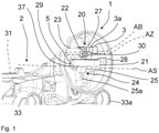
- an electromechanical actuator 1 with a disc brake 2 is shown.
- the disk brake 2 has a brake caliper 31 axially along a disk brake axis AS.
- the caliper 31 is slidably mounted on a brake carrier, not shown, via two guide bushings 33, 33a.
- the electromechanical actuator 1 is flanged to the brake caliper 31 and clamps a brake disc, not shown, via a rotary lever 5, a pressure plate, not shown and two brake pads, not shown.
- the electromechanical actuator 1 has an electric motor 3 with a gear 3a for generating a rotary drive torque.
- a rack and pinion gear 20 converts the rotational movement of the electric motor 3 into a translatory movement.
- the rack and pinion gear 20 has a toothed rack 21 , a drive gear wheel 22 and an actuating shaft 23 for converting a rotational movement into a translatory movement.
- the toothed rack 21 is operatively connected axially, with respect to an axial axis A of the toothed rack 21 , via a receptacle 29 of the toothed rack 21 to the rotary lever 5 .
- the receptacle 29 of the toothed rack 21 corresponds to a ball head 29 , the ball head 29 being arranged in a recess 37 of the rotary lever 5 .
- the ball head 29 and the recess 37 of the rotary lever 5 together form a bearing and compensate for the rotary movement of the rotary lever 5 .
- the rack and pinion gear 20 is set in motion via the actuating shaft 23 which is operatively connected to the electric motor 3 .
- the actuation shaft 23 engages through a cylindrical passage 30 of the drive gear 22, with the actuation shaft 23 transmitting the rotational movement to the drive gear 22.
- the actuating shaft 23 and the drive gear wheel 22 are offset relative to one another with respect to a drive gear wheel axis AZ of the drive gear wheel 22 and an actuation shaft axis AB of the actuation shaft 23 .
- the drive gear 22 In order to transfer the rotational movement of the drive gear 22 to a translatory movement of the toothed rack 21, the drive gear 22 has teeth 27 on the peripheral surface. The teeth 27 of the drive gear 22 engage in teeth 28 of the rack 21.
- the rack and pinion gear 20 also has a spring-loaded roller 24 on the side of the rack 21 opposite the drive gear 22.
- the spring-loaded roller 24 is composed of a support roller 25 and a spring 25a.
- the spring 25a is prestressed and presses the support roller 25 radially against the toothed rack 21.
- the spring-loaded roller 24 equals during an application movement or a return movement of the brake pads, not shown, a radial movement of the rack 21, whereby the teeth 27 of the drive gear 22 are in permanent engagement with the toothing 28 of the rack 21.
- In 2 is the rack and pinion gear 20 with the spring-loaded roller 24 after 1 shown again in detail.
- Mainly clarified 2 the operation of the rack and pinion gear 20.
- the drive gear 22 is not completely circular in the peripheral surface.
- the drive gear wheel 22 is circular at a twist angle of 0 degrees to 270 degrees and has teeth 27 .
- a first small gear reduction of the rack and pinion gear 20 is achieved by offsetting the actuating shaft axis AB of the actuating shaft 23 and the drive gear axis AZ of the drive gear 22 .
- the drive gear 22 is in a starting position with a twist angle of 60 degrees.
- a twist angle range of the drive gear 22 from 0 degrees to 60 degrees is used to bridge a clearance of the disc brake 2.
- the rack and pinion gear 20 has the smallest reduction. After a rotary movement of the drive gear 22 in a twist angle between 180 degrees and 270 degrees, the greatest possible reduction of the rack and pinion gear 20 is reached.
- the rotary lever 5 moves within a 180 degree movement of the actuating shaft 23 from a minimum deflection of the rotary lever 5 to a maximum deflection of the rotary lever 5.
- the position of the drive gear 22 and that of the rotary lever 5 is designed so that the rotary lever 5 after a Rotation of the actuating shaft 23 by 45 degrees reaches the minimum deflection and the rotary lever 5 reaches the maximum deflection after a rotation of the actuating shaft 23 by 210 degrees.
- In 3 is the rack and pinion gear 20 after figure 1 and figure 2 shown in a second embodiment.
- the rack and pinion gear 20 has against the 1 and 2 no spring-loaded roller 24, but a cam track 26 on.
- the curve 26a of the cam track 26 rises, as a result of which a pressure P is exerted on the rack 21 via the support roller 25 in order to prevent a radial movement of the rack 21, counter to the direction of the drive gear 22.
- both the toothed rack 21 and the teeth 28 of the toothed rack 21 are shaped conically in the direction of the rotary lever 5, which means that stresses on the teeth 27 of the drive gear 22 and stresses on the teeth 28 of the toothed rack 21 during a rotary movement of the drive gear 22 be minimized.
- the width of the teeth 28 increases in the direction of a vertical axis AV.
- figure 5 shows the teeth 27 of the drive gear 22 after the Figures 1 to 4 and the teeth 28 of the rack 21 according to Figures 1 to 4 in detail.
- Both the teeth 27 of the drive gear 22 and the teeth 28 of the toothed rack 21 are sawtooth-shaped.
- the sawtooth configuration of the teeth 27 of the drive gear 22 and the teeth 28 of the rack 21 minimize transverse forces in the rack and pinion 20, which are triggered by the spring-loaded roller 24 or the curved track 26.
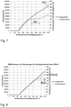
- the figures 6 and 7 show a graphics of an electromechanical actuator 1 after 1 with a rack 21, and a drive gear 22 with an offset after the Figures 1 to 5 .
- the driving gear 22 is referred to as gear 22 .
- gear 22 In 6 a situation is shown in which the drive gear 22 has a diameter of 27 mm and an offset of the drive gear axis AZ with respect to the actuating shaft axis AB of the actuating shaft 23 is 4 mm.
- a maximum twisting angle Amax of the rotary lever 5 of 17.5 mm is achieved with a twisting angle of the actuating shaft 23 of 45 degrees. After a rotation of the actuating shaft 23 by 225 degrees, the rotary lever 5 reaches a minimum angle of rotation Amin of 9.5 mm.
- the maximum translational movement BTmax of the toothed rack 21 is 65 mm with a twisting angle of the actuating shaft 23 of 270 degrees.
- the relationship between the stroke of the toothed rack 21, i.e. the translational movement, the clamping force and the drive torque on the actuating shaft 23 is in 7 shown.
- the application force increases in relation to the drive torque up to an angle of rotation of 120 degrees in an approximately linear manner.
- the electromechanical actuator 1 has an application force of 100,000 N and a drive torque of 100 Nm. In the range from 60 degrees to 120 degrees of the drive gear 22, the electromechanical brake actuator 1 clamps the brake disk.
- the area Bp1 for engaging a parking lock of disc brake 1 As area Bp1 for engaging a parking lock of disc brake 1 (see figure 1 ) the area Bp1 is defined with a drive torque of about 100 Nm and a rotation angle of about 150 degrees to 210 degrees. The clamping force also increases linearly as far as possible in the area Bp1 for engaging the parking lock. A drive torque Am of 100 Nm is applied to the actuation shaft 23 to fully engage the parking lock. The maximum clamping force is achieved with a drive torque of 140 Nm.
- figure 8 shows the graphic figure 7 , but without an offset of the drive gear wheel axis AZ in relation to the actuating shaft axis AB of the actuating shaft 23. It is easy to see that the drive torque Am2 on the actuating shaft 23 is 185 Nm, instead of after 7 is 140 Nm. In addition, the range Bp2 for engaging the parking lock between 135 Nm and 140 Nm is significantly higher than the range Bp1 of 100 Nm to engage the parking lock of an electromechanical brake actuator 1 7 .
Landscapes
- Engineering & Computer Science (AREA)
- General Engineering & Computer Science (AREA)
- Mechanical Engineering (AREA)
- Braking Arrangements (AREA)
- Transmission Devices (AREA)
Description
- Die Erfindung betrifft einen elektromechanischen Aktuator für eine Scheibenbremse. Elektromechanische Aktuatoren sind hinlänglich bekannt. Aktuelle Entwicklungen im Bereich der Nutzfahrzeugscheibenbremsen gehen hin zu elektromechanischen Aktuatoren mit einer Kurvenscheibe.
- Die
DE102017004436A1 zeigt einen solchen elektromechanischen Aktuator mit einer Kurvenscheibe. Die Kurvenscheibe ist rotatorisch beweglich auf einer Betätigungswelle gelagert und wird über einen Elektromotor angetrieben, wobei der Elektromotor ein Antriebsmoment erzeugt. Ein sogenannter Bremsstößel ist mit der Kurvenscheibe und einem Drehhebel der Scheibenbremse wirkverbunden. Die Kurvenscheibe wandelt zur Aktuierung des Drehhebels die rotatorische Bewegung der Betätigungswelle in eine translatorische Bewegung um, wobei der Drehhebel eine Bremsscheibe über eine Druckplatte und zwei Bremsbeläge zuspannt. Mittels einem, mit der Betätigungswelle wirkverbundenen Getriebe kann die Untersetzung des Antriebsmoments, und damit die lineare Zustellbewegung des Bremsstößels variiert werden. - Ein weiterer elektromechanischer Aktuator ist in der
US200050029858A1 KR20030093690A - Nachteilig sind die hohe Anzahl an Bauteilen, insbesondere durch die Kurvenscheibe, dem zusätzlichen Getriebe, und die damit verbundene Bauteilgröße des elektromechanischen Aktuators. Die Bauteilgröße führt wiederum insbesondere zu Problemen beim Einbau des elektromechanischen Aktuators in eine Vorderachse oder in eine Hinterachse eines Fahrzeugs. Darüber hinaus können Elektromotoren nur ein geringes Antriebsdrehmoment aufbringen. Zum Zuspannen der Bremsscheibe sind allerdings hohe Zuspannkräfte notwendig. Das heißt, dass zum Zuspannen der Bremsscheibe mit dem geringen Antriebsmoment ein Getriebe mit einer großen Untersetzung erforderlich ist. Eine große Untersetzung hat allerdings zur Folge, dass die Aktuierungszeit, also die Zeit zum Zuspannen der Bremsscheibe, größer ist als bei einem Getriebe mit einer kleinen Untersetzung.
- Aufgabe der Erfindung ist es, einen kompakt bauenden elektromechanischen Aktuator bereit zu stellen.
- Gelöst wird die Aufgabe dadurch, dass der elektromechanische Aktuator entlang einer axialen Achse ein stufenlos einstellbares Zahnstangengetriebe zur Betätigung eines Drehhebels einer Scheibenbremse aufweist und mit einer Betätigungswelle des elektromechanischen Aktuators wirkverbunden ist. Ein mit der Betätigungswelle wirkverbundener Antrieb, insbesondere ein Elektromotor, versetzt die Betätigungswelle in eine rotatorische Bewegung, wobei die rotatorische Bewegung auf das Antriebszahnrad übertragen wird. Weiterhin weist zum Einlegen einer Parksperre das Zahnstangengetriebe gegenüber einem elektromechanischen Aktuator mit einer Kurvenscheibe den Vorteil auf, das zum Beginn eines Bremsvorgangs eine schnelle lineare Zustellbewegung mit einem hohen Antriebsmoment der Bremsscheibe über die Bremsbeläge erfolgt und mit zunehmender Zustellbewegung das Antriebsmoment abnimmt. Es ist also ein Motor mit einem geringeren Drehmoment zum Aufbringen einer Zuspannkraft notwendig. Als Zuspannkraft ist die aufzubringende Kraft des elektromechanischen Aktuators zum Zuspannen der Bremsscheibe über die Bremsbeläge definiert.
- Das Zahnstangengetriebe umfasst erfindungsgemäß eine Zahnstange und ein mit der Zahnstange wirkverbundenes Antriebs-zahnrad. Die Zahnstange setzt eine Drehbewegung des Antriebszahnrads in eine Linearbewegung, also in eine translatorische Bewegung um, wodurch der Drehhebel der Scheibenbremse in eine Drehbewegung entlang einer axialen Achse der Zahnstange versetzt wird und eine Bremsscheibe zumindest über eine Druckplatte und Bremsbeläge zuspannt. Die Bewegung der Zahnstange in Richtung der Bremsscheibe wird als Zuspannbewegung bezeichnet. Während einer Rückstellbewegung, also einer entgegengesetzt der Zuspannbewegung gerichteten axialen Bewegung der Zahnstange, wird durch das Antriebszahnrad die lineare Bewegung der Zahnstange in eine Drehbewegung umgewandelt, wodurch die Bremsbeläge von der Bremsscheibe gelöst werden.
- Die Betätigungswelle ist, bezogen auf eine Antriebszahnradachse des Antriebszahnrades, erfindungsgemäß versetzt an dem Antriebszahnrad angeordnet. Die versetzt an dem Antriebszahnrad angeordnete Betätigungswelle erzeugt zu Beginn des Zuspannvorgangs eine kleine Untersetzung, wobei die Untersetzung mit einer zunehmenden Zuspannkraft zunimmt. Die Zuspannkraft einer Scheibenbremse eines Nutzfahrzeugs beträgt für Anpassungsbremsungen gewöhnlich 30.000 N. Die Zuspannkraft für Vollbremsungen beträgt gewöhnlich mindestens 200.000 N. Die aufzubringende Zuspannkraft variiert je nach Fahrzeug und Scheibenbremsentyp. Zum Einlegen einer Parksperre sind im Mittel Antriebsmomente von etwa 140 Nm erforderlich. Auch die Zuspannkräfte können je nach Fahrzeug und Scheibenbremsentyp abweichen. Die versetzt angeordnete Betätigungswelle reduziert das Antriebsmoment im Mittel um 25 %. Das heißt, dass sich ein erforderliches Antriebsmoment zum Zuspannen einer Bremssscheibe von 185 Nm auf 140 Nm reduziert. Zudem reduziert sich das aufzubringende Antriebsmoment zum Einlegen der Parksperre von 135 Nm bis 140 Nm im Mittel auf 100 Nm. Erreicht wird die Verringerung der Antriebsmomente zum Einlegen der Parksperre durch ein Antriebsmo-mentenplateau. Ein Steuersystem erkennt über Sensoren das erforderliche Antriebsmoment zum Zuspannen der Parksperre. Die Zuspannkraft und das Antriebsmoment verlaufen bis zum Erreichen des erforderlichen Antriebsmoments zum Zuspannen der Parksperre in etwa parallel. Sobald das erforderliche Antriebsmoment erreicht worden ist, bleibt das Antriebsmoment in einem Drehwinkelabschnitt des Antriebszahnrads etwa gleich, wobei die Zuspannkraft linear weiter ansteigt.
- Der Versatz der Betätigungswelle wird in einer weiteren Ausgestaltung dadurch erreicht, dass das Antriebszahnrad in Richtung der Antriebszahnradachse einen zylinderförmigen Durchgang zur Aufnahme der Betätigungswelle aufweist. Der Abstand zwischen den, bezogen auf die Antriebszahnradachse, radialen Begrenzungen des zylinderförmigen Durchgangs ist größer als der Abstand zwischen den axialen Begrenzungen des zylinderförmigen Durchgangs. Der zylinderförmige Durchgang ermöglicht eine variable Anpassung der Untersetzung des Antriebszahnrads, und damit der Anpassung des Antriebsmoments.
- In einer weiteren vorteilhaften Ausgestaltung weist die Zahnstange, bezogen auf die axiale Achse, radial, auf der dem Antriebszahnrad gegenüberliegenden Seite der Zahnstange, eine federbelastete Rolle auf. Die federbelastete Rolle gleicht, bezogen auf die axiale Achse der Zahnstange, eine radiale Bewegung der Zahnstange aus. Eine radiale Bewegung der Zahnstange entsteht unter anderen während einer Zustellbewegung oder einer Rückstellbewegung des Zahnstangengetriebes. Die federbelastete Rolle ist radial unterhalb des Antriebszahnrads an der Zahnstange angeordnet. Die federbelastete Rolle stützt sich daher an der Zahnstange ab, damit die Zahnstange und das Antriebszahnrad dauerhaft wirkverbunden sind und das Aufbringen der vollständigen Bremskraft zum Zuspannen der Bremsscheibe gewährleistet ist. Die federbelastete Rolle verhindert also eine Unterbrechung der Linearbewegung der Zahnstange, aufgrund einer der Zahnstange radial entgegengesetzten Bewegung des Antriebszahnrads.
- Zur Vermeidung einer Unterbrechung der Linearbewegung der Zahnstange, weist in einer alternativen Ausgestaltung die Zahnstange des Zahnstangengetriebes, bezogen auf die axiale Achse, radial auf der dem Antriebszahnrad gegenüberliegenden Seite der Zahnstange eine Stützrolle auf und die Zahnstange weist auf der dem Antriebszahnrad gegenüberliegenden Seite der Zahnstange eine Kurvenbahn auf, wobei sich die Stützrolle entlang der Kurvenbahn abstützt. Die Kurvenbahn steigt während eines Zuspannvorgangs der Scheibenbremse oder eines Rückstellvorgangs der Scheibenbremse, ausgelöst durch eine Drehbewegung des Drehhebels und einer damit verbundenen Radialbewegung der Zahnstange, leicht an.
- In einer weiteren Ausgestaltung ist das Antriebszahnrad kreisförmig ausgebildet und das Antriebszahnrad weist in einem Verdrehwinkel von 30 Grad bis 300 Grad Zähne auf. Die Zähne greifen in Zahnabstände der Zahnstange ein. Die nicht mit Zähnen besetzte Fläche des Antriebszahnrads definiert einen Grenzbereich, also eine maximale Auslegung des Drehhebels durch die Zahnstange und eine minimale Auslegung des Drehhebels durch die Zahnstange.
- Die Zähne des Antriebszahnrads und die Zähne der Zahnstange sind in einer Weiterbildung sägezahnförmig ausgebildet. Dabei sind die schrägen Flanken der Zähne der Zahnstange in Richtung des Drehhebels gerichtet. Die schrägen Flanken des Antriebszahnrads sind entgegengesetzt der Richtung des Drehhebels an dem Antriebszahnrad angeordnet. Während einer Zustellbewegung stützen sich die in Eingriff stehenden radialen Flanken der Zähne der Zahnstange an den radialen Flanken des Antriebszahnrads ab und eine axiale Linearbewegung in Richtung des Drehhebels erfolgt. Die Anordnung erlaubt eine Übertragung von Antriebsmomenten mit einer Kraft von mindestens 100 Nm.
- In einer weiteren Ausgestaltung sind die Zähne der Zahnstange konisch, also kegelförmig, ausgebildet. Die Zähne nehmen in ihrer Dimensionierung, entgegengesetzt der Richtung des Drehhebels, zu. Die Zähne werden daher entlang einer horizontalen Achse in ihrer Dimensionierung breiter. Die konische Geometrie der Zähne auf der Zahnstange verringert Spannungen an den Zähnen der Zahnstange und an den Zähnen des Antriebsrads bei hohen Antriebsmomenten, oder anders ausgedrückt, sobald die Bremsbeläge an der Bremsscheibe anliegen und weiter zugespannt werden, entstehen hohe Antriebsmomente. Zusätzlich dient die konische Ausgestaltung der Zahnstange dazu, dass die Zahnstange zur Betätigung des Drehhebels mit ihrer stirnseitig schmalsten Abmessung durch eine Öffnung des Aktuatorgehäuses passt.
- In einer weiteren Ausgestaltung weist die Zahnstange eine Aufnahme zur Betätigung des Drehhebels auf. Die Aufnahme ist stirnseitig an der Zahnstange angeordnet und kugelförmig ausgebildet. Die Aufnahme wirkt gleichzeitig als Drehgelenk zum Ausgleich von Kippbewegungen des Drehhebels.
- In einer letzten Ausgestaltung ist das Antriebszahnrad dazu ausgebildet in einem Verdrehwinkel zwischen 0 Grad bis 60 Grad ein Lüftspiel der Scheibenbremse zu überbrücken und in einem Winkel zwischen 30 Grad und 250 Grad eine Scheibenbremse zuzuspannen oder eine Scheibenbremse in einem Winkel zwischen 30 Grad und 250 Grad in einer Parksperrposition zu halten. Das Antriebszahnrad überbrückt mit einer kleinen Untersetzung des Zahnstangengetriebes das Lüftspiel der Scheibenbremse zwischen einem Verdrehwinkel von 0 Grad bis 30 Grad, ohne eine Zuspannkraft aufzubringen. Die Überbrückung des Lüftspiels der Scheibenbremse kann je nach Fahrzeug und Scheibenbremse bis zu einem Verdrehwinkel von 60 Grad des Antriebszahnrads variieren. Das Antriebszahnrad hat daher zu Beginn eines Bremsvorgangs eine Ausgangstellung zwischen 30 Grad und 60 Grad, wobei das Zahnstangengetriebe in dem Bereich zwischen 30 Grad und 90 Grad die niedrigste Untersetzung aufweist. Bis zu einem Verdrehwinkel des Antriebszahnrads von 210 Grad weist das Zahnstangengetriebe eine relativ kleine Untersetzung auf. Das heißt, dass das Zahnstangengetriebe für einen Anpassungsbremsvorgang einen kleinen Verdrehwinkel bei einer kleinen Untersetzung aufweist. Bis zu einem Verdrehwinkel von 210° gleitet die Untersetzung auf ihren Größtwert. Im Bereich der Parksperre heben sich Zunahme der Zuspannkraft und Zunahme der Untersetzung nahezu auf. So dass das Antriebsmoment nur gering ansteigt.
- Im Falle einer Notbremsung eines Fahrzeugs, weist das Antriebszahnrad über einen Verdrehwinkel zwischen 180 Grad bis 270 Grad zum Aufbringen der erforderlichen Zuspannkräfte eine große Untersetzung auf. Als Zuspannkraft ist die Kraft definiert, die erforderlich ist, um eine Bremsscheibe über Bremsbeläge der Scheibenbremse abzubremsen. Nachfolgend werden ausgewählte Ausführungsbeispiele der Erfindung anhand der beigefügten Figuren erläutert.
- Nachfolgend werden ausgewählte Ausführungsbeispiele der Erfindung anhand der beigefügten Figuren erläutert.
- Es zeigt:
-
Fig. 1 eine Scheibenbremse mit einem elektromechanischen Aktuator mit einem Zahnstangengetriebe aus einer seitlich gedrehten Ansicht, -
Fig. 2 eine schematische Ansicht eines Zahnstangengetriebes mit einer federbelasteten Rolle, -
Fig. 3 eine schematische Ansicht eines Zahnstangengetriebes mit einer Kurvenbahn, -
Fig. 4 eine Draufsicht eines schematisch dargestellten Zahnstangengetriebes, -
Fig. 5 eine Detailansicht eines Zahneingriffs des Zahnstangengetriebes mit Zähnen in Sägezahnform, -
Fig. 6 bis Fig. 7 grafische Darstellungen des elektromechanischen Aktuators mit einer Zahnstange und einem Antriebszahnrad mit einem Versatz, -
Fig. 8 eine grafische Darstellung des elektromechanischen Aktuators mit einer Zahnstange und einem Antriebszahnrad ohne einen Versatz, - In
Fig. 1 ist ein elektromechanischer Aktuator 1 mit einer Scheibenbremse 2 gezeigt. Die Scheibenbremse 2 weist, axial, entlang einer Scheibenbremsenachse AS, einen Bremssattel 31 auf. Der Bremssattel 31 ist über zwei Führungsbuchsen 33, 33a an einem nicht gezeigten Bremsträger gleitend gelagert. Der elektromechanische Aktuator 1 ist an dem Bremssattel 31 angeflanscht und spannt eine nicht gezeigte Bremsscheibe über einen Drehhebel 5, einer nicht gezeigten Druckplatte und zwei nicht gezeigten Bremsbelägen zu. Der elektromechanische Aktuator 1 weist einen Elektromotor 3 mit einem Getriebe 3a zum Erzeugen eines rotatorischen Antriebsmoments auf. Ein Zahnstangengetriebe 20 wandelt die rotatorische Bewegung des Elektromotors 3 in eine translatorische Bewegung um. Zur Umwandlung von einer rotatorischen Bewegung in eine translatorische Bewegung weist das Zahnstangengetriebe 20 eine Zahnstange 21, einem Antriebszahnrad 22 und einer Betätigungswelle 23 auf. Die Zahnstange 21 ist axial, in Bezug auf eine Axiale Achse A der Zahnstange 21, über eine Aufnahme 29 der Zahnstange 21 mit dem Drehhebel 5 wirkverbunden. Die Aufnahme 29 der Zahnstange 21 entspricht einem Kugelkopf 29, wobei der Kugelkopf 29 in eine Ausnehmung 37 des Drehhebels 5 angeordnet ist. Der Kugelkopf 29 und die Ausnehmung 37 des Drehhebels 5 bilden zusammen ein Lager und gleichen die Drehbewegung des Drehhebels 5 aus. Das Zahnstangengetriebe 20 wird über die mit dem Elektromotor 3 wirkverbundene Betätigungswelle 23 in Bewegung versetzt. Die Betätigungswelle 23 greift durch einen zylinderförmigen Durchgang 30 des Antriebszahnrads 22, wobei die Betätigungswelle 23 die rotatorische Bewegung auf das Antriebszahnrad 22 überträgt. Die Betätigungswelle 23 und das Antriebszahnrad 22 sind bezogen auf eine Antriebszahnradachse AZ des Antriebszahnrads 22 und eine Betätigungswellenachse AB der Betätigungswelle 23 versetzt zueinander angeordnet. Zur Übertragung der rotatorischen Bewegung des Antriebszahnrads 22 auf eine translatorische Bewegung der Zahnstange 21 weist das Antriebszahnrad 22 an der Umfangsfläche Zähne 27 auf. Die Zähne 27 des Antriebszahnrads 22 greifen in eine Verzahnung 28 der Zahnstange 21. Das Zahnstangengetriebe 20 weist darüber hinaus an der dem Antriebszahnrad 22 gegenüberliegenden Seite der Zahnstange 21 eine federbelastete Rolle 24 auf. Die federbelastete Rolle 24 setzt sich aus einer Stützrolle 25 und einer Feder 25a zusammen. Die Feder 25a ist vorgespannt und drückt die Stützrolle 25 radial gegen die Zahnstange 21. Die federbelastete Rolle 24 gleicht während einer Zuspannbewegung oder einer Rückstellbewegung der nicht gezeigten Bremsbeläge eine radiale Bewegung der Zahnstange 21 aus, wodurch die Zähne 27 des Antriebszahnrads 22 im dauerhaften Eingriff mit der Verzahnung 28 der Zahnstange 21 stehen. - In
Fig. 2 ist das Zahnstangengetriebe 20 mit der federbelasteten Rolle 24 nachFig. 1 noch einmal im Detail gezeigt. Vor allem verdeutlichtFig. 2 die Funktionsweise des Zahnstangegetriebes 20. Das Antriebszahnrad 22 ist in der Umfangsfläche nicht vollständig kreisrund. In Figur 2 ist das Antriebszahnrad 22 in einem Verdrehwinkel von 0 Grad bis 270 Grad kreisrund und mit Zähnen 27 besetzt. Eine erste kleine Untersetzung des Zahnstangengetriebes 20 wird durch den Versatz der Betätigungswellenachse AB der Betätigungswelle 23 und der Antriebszahnradachse AZ des Antriebszahnrads 22 erreicht. Das Antriebszahnrad 22 befindet sich in einer Ausgangsstellung mit einem Verdrehwinkel von 60 Grad. Ein Verdrehwinkelbereich des Antriebszahnrads 22 von 0 Grad bis 60 Grad dient der Überbrückung eines Lüftspiels der Scheibenbremse 2. Bei einem Verdrehwinkel von 60 Grad des Antriebszahnrads 22 weist das Zahnstangengetriebe 20 die kleinste Untersetzung auf. Nach einer Drehbewegung des Antriebszahnrads 22 in einem Verdrehwinkel zwischen 180 Grad bis 270 Grad ist die größtmögliche Untersetzung des Zahnstangengetriebes 20 erreicht. Der Drehhebel 5 bewegt sich innerhalb einer 180 Grad Bewegung der Betätigungswelle 23 von einer minimalen Auslenkung des Drehhebels 5 hin zu einer maximalen Auslenkung des Drehhebels 5. Zusätzlich ist die Stellung des Antriebszahnrads 22 und der des Drehhebels 5 so ausgelegt, dass der Drehhebel 5 nach einer Rotation der Betätigungswelle 23 um 45 Grad, die minimale Auslenkung erreicht und das der Drehhebel 5 nach einer Rotation der Betätigungswelle 23 um 210 Grad die maximale Auslenkung erreicht. - In
Fig. 3 ist das Zahnstangengetriebe 20 nachFigur 1 undFigur 2 in einer zweiten Ausführung gezeigt. Das Zahnstangengetriebe 20 weist entgegen derFig. 1 undFig. 2 keine federbelastete Rolle 24, sondern eine Kurvenbahn 26 auf. Mit zunehmender Auslenkung des Drehhebels 5 und der Zunahme einer Zuspannkraft (s.Fig. 7 ) des elektromechanischen Bremsaktuators 1 (Fig. 1 ) steigt die Kurve 26a der Kurvenbahn 26 an, wodurch über die Stützrolle 25 auf die Zahnstange 21 ein Druck P zur Verhinderung einer radialen Bewegung der Zahnstange 21, entgegen der Richtung des Antriebszahnrads 22, ausgeübt wird. -
Fig. 4 zeigt das Zahnstangengetriebe 20 aus der Draufsicht nach denFiguren 1 bis 3 . Deutlich sichtbar ist, sowohl die Zahnstange 21, als auch die Verzahnung 28 der Zahnstange 21 sind konisch in Richtung des Drehhebels 5 geformt, wodurch Spannungen an den Zähnen 27 des Antriebszahnrads 22 und Spannungen an der Verzahnung 28 der Zahnstange 21 während einer Drehbewegung des Antriebszahnrads 22 minimiert werden. Die Breite der Verzahnung 28 nimmt in Richtung einer vertikalen Achse AV zu. -
Fig. 5 zeigt die Zähne 27 des Antriebszahnrads 22 nach denFiguren 1 bis 4 und die Verzahnung 28 der Zahnstange 21 nach denFiguren 1 bis 4 im Detail. Sowohl die Zähne 27 des Antriebszahnrads 22, als auch die Verzahnung 28 der Zahnstange 21 sind sägezahnförmig ausgestaltet. Die sägezahnförmige Ausgestaltung der Zähne 27 des Antriebszahnrads 22 und der Verzahnung 28 der Zahnstange 21 minimieren Querkräfte im Zahnstangengetriebe 20, welche durch die federbelastete Rolle 24 oder der Kurvenbahn 26 ausgelöst werden. - Die
Figuren 6 und7 zeigen eine Grafiken eines elektromechanischen Aktuators 1 nachFig. 1 mit einer Zahnstange 21, sowie einem Antriebszahnrad 22 mit einem Versatz nach denFiguren 1 bis 5 . Das Antriebszahnrad 22 ist als Zahnrad 22 bezeichnet. InFig. 6 ist eine Situation gezeigt, bei der das Antriebszahnrad 22 einen Durchmesser von 27 mm und einen Versatz der Antriebszahnradachse AZ in Bezug auf die Betätigungswellenachse AB der Betätigungswelle 23 von 4 mm aufweist. Ein maximaler Verdrehwinkel Amax des Drehhebels 5 von 17,5 mm wird bei einem Verdrehwinkel der Betätigungswelle 23 von 45 Grad erreicht. Nach einer Rotation der Betätigungswelle 23 um 225 Grad erreicht der Drehhebel 5 einem minimalen Verdrehwinkel Amin von 9,5 mm. Die maximale translatorische Bewegung BTmax der Zahnstange 21 beträgt 65 mm bei einem Verdrehwinkel der Betätigungswelle 23 von 270 Grad. Der Zusammenhang zwischen dem Hub der Zahnstange 21, also der translatorischen Bewegung, der Zuspannkraft und dem Antriebsmoment an der Betätigungswelle 23 ist inFig. 7 gezeigt. Ab einem Verdrehwinkel des Antriebszahnrads 22 von 60 Grad steigt die Zuspannkraft bezogen auf das Antriebsmoment bis zu einem Verdrehwinkel von 120 Grad in etwa linear an. Bei dem Verdrehwinkel von 120 Grad weist der elektromechanische Aktuator 1 eine Zuspannkraft von 100.000 N und ein Antriebsmoment von 100 Nm auf. In dem Bereich von 60 Grad bis 120 Grad des Antriebszahnrads 22 spannt der elektromechanische Bremsaktuator 1 die Bremsscheibe zu. Als Bereich Bp1 zum Einlegen einer Parksperre der Scheibenbremse 1 (s.Figur 1 ) ist der Bereich Bp1 mit einem Antriebsmoment von etwa 100 Nm und einem Drehwinkel von etwa 150 Grad bis 210 Grad definiert. Die Zuspannkraft steigt auch im Bereich Bp1 zum Einlegen der Parksperre weitestgehend linear weiter an. Zum vollständigen Einlegen der Parksperre liegt ein Antriebsmoment Am von 100 Nm an der Betätigungswelle 23 an. Die maximale Zuspannkraft wird bei einem Antriebsmoment von 140 Nm erreicht. -
Figur 8 zeigt die Grafik nachFigur 7 , jedoch ohne einen Versatz der Antriebszahnradachse AZ in Bezug auf die Betätigungswellenachse AB der Betätigungswelle 23. Gut zu erkennen ist, dass das Antriebsmoment Am2 an der Betätigungswelle 23 185 Nm, anstatt nachFig. 7 140 Nm beträgt. Zudem ist der Bereich Bp2 zum Einlegen der Parksperre zwischen 135 Nm und 140 Nm deutlich höher als der Bereich Bp1 von 100 Nm zum Einlegen der Parksperre eines elektromechanischen Bremsenaktuators 1 nachFig. 7 . -
- 1
- Elektromechanischer Aktuator
- 2
- Scheibenbremse
- 3
- Elektromotor
- 3a
- Getriebe
- 5
- Drehhebel
- 20
- Zahnstangengetriebe
- 21
- Zahnstange
- 22
- Antriebszahnrad
- 23
- Betätigungswelle
- 24
- federbelastete Rolle
- 25
- Stützrolle
- 25a
- Feder
- 26
- Kurvenbahn
- 26a
- Kurve der Kurvenbahn 26
- 27
- Zähne
- 28
- Verzahnung der Zahnstange 21
- 29
- als Kugelkopf ausgebildete Aufnahme der Zahnstange 21
- 30
- zylinderförmiger Durchgang des Antriebszahnrads 29
- 31
- Bremssattel
- 33, 33a
- Führungsbuchsen
- 37
- Ausnehmung des Drehhebels 5
- A
- axiale Achse der Zahnstange 21
- AB
- Betätigungswellenachse
- Am1, Am2
- Antriebsmomente an der Betätigungswelle 23
- Amin
- minimaler Verdrehwinkel der Betätigungswelle 23
- Amax
- maximaler Verdrehwinkel der Betätigungswelle 23
- AS
- Scheibenbremsenachse
- AV
- vertikale Achse der Zahnstange 21
- AZ
- Antriebszahnradachse
- Bp1, Bp2
- Bereiche zum Einlegen einer Parksperre der Scheibenbremse 1
- BTmax
- maximale translatorische Bewegung der Zahnstange 21
- P
- Druck
Claims (9)
- Elektromechanischer Aktuator (1) für eine Scheibenbremse (2), insbesondere für eine Nutzfahrzeugscheibenbremse, mit einem Elektromotor (3) und einem Getriebe (3a) zum Erzeugen eines Antriebsmoments (M) und einer mit dem Elektromotor (3) wirkverbundenen rotatorisch beweglich gelagerten Betätigungswelle (23), wobei der elektromechanische Aktuator (1) entlang einer axialen Achse (A) ein mit der Betätigungswelle (23) wirkverbundenes Zahnstangengetriebe (20) zur Betätigung eines Drehhebels (5) der Scheibenbremse (2) aufweist, wobei das Zahnstangengetriebe (20) eine Zahnstange (21) und ein mit der Zahnstange (21) wirkverbundenden Antriebszahnrad (22) umfasst, dadurch gekennzeichnet, dass die Betätigungswelle (23), bezogen auf eine Antriebszahnradachse (AZ), versetzt an dem Antriebszahnrad (22) angeordnet ist.
- Elektromechanischer Aktuator (1) nach Anspruch 1, dadurch gekennzeichnet, dass das Antriebszahnrad (22) in Richtung der Antriebszahnradachse (AZ) einen zylinderförmigen Durchgang 29 zur Aufnahme der Betätigungswelle (23) aufweist.
- Elektromechanischer Aktuator (1) nach Anspruch 1 oder 2, dadurch gekennzeichnet, dass die Zahnstange (21), bezogen auf die axiale Achse (A), radial, auf der dem Antriebszahnrad (21) gegenüberliegenden Seite der Zahnstange (21) eine federbelastete Rolle (24) aufweist.
- Elektromechanischer Aktuator (1) nach einem der Ansprüche 1 bis 3, dadurch gekennzeichnet, dass die Zahnstange (21), bezogen auf die axiale Achse (A), radial, auf der dem Antriebszahnrad (22) gegenüberliegenden Seite der Zahnstange (21) eine Stützrolle (25) aufweist und die Zahnstange (21) auf der dem Antriebszahnrad (22) gegenüberliegenden Seite der Zahnstange (21) eine Kurvenbahn (26) aufweist und die Stützrolle (24) sich entlang der Kurvenbahn (25) abstützt.
- Elektromechanischer Aktuator (1) nach einem Ansprüche 1 bis 4, dadurch gekennzeichnet, dass das Antriebszahnrad (22) kreisförmig ausgebildet ist und in einem Verdrehwinkel von 30 Grad bis 300 Grad Zähne (27) aufweist.
- Elektromechanischer Aktuator (1) nach Anspruch 5, dadurch gekennzeichnet, dass die Zähne (27) sägezahnförmig ausgebildet sind.
- Elektromechanischer Aktuator (1) nach einem der Ansprüche 1 bis 6, dadurch gekennzeichnet, dass die Zahnstange (21) auf der Seite des Antriebszahnrads (22), entlang der axialen Achse (A), eine Verzahnung (28) aufweist und die Verzahnung (28) axial in Richtung des Drehhebels (5) konisch ausgebildet ist.
- Elektromechanischer Aktuator (1) nach einem der Ansprüche 1 bis 7, dadurch gekennzeichnet, dass die Zahnstange (21) eine Aufnahme (29) zur Betätigung des Drehhebels (5) aufweist.
- Elektromechanischer Aktuator (1) nach einem der Ansprüche 1 bis 8, dadurch gekennzeichnet, dass das Antriebszahnrad (22) dazu ausgebildet ist in einem Verdrehwinkel zwischen 0 Grad bis 60 Grad ein Lüftspiel der Scheibenbremse (2) zu überbrücken und in einem Winkel zwischen 30 Grad und 270 Grad eine Scheibenbremse zuzuspannen oder eine Scheibenbremse (2) in einem Winkel zwischen 60 Grad und 270 Grad in einer Parksperrposition zu halten
Applications Claiming Priority (1)
| Application Number | Priority Date | Filing Date | Title |
|---|---|---|---|
| DE102019119839.9A DE102019119839A1 (de) | 2019-07-23 | 2019-07-23 | Elektromechanischer Aktuator |
Publications (2)
| Publication Number | Publication Date |
|---|---|
| EP3770456A1 EP3770456A1 (de) | 2021-01-27 |
| EP3770456B1 true EP3770456B1 (de) | 2022-03-02 |
Family
ID=71527628
Family Applications (1)
| Application Number | Title | Priority Date | Filing Date |
|---|---|---|---|
| EP20184653.2A Active EP3770456B1 (de) | 2019-07-23 | 2020-07-08 | Elektromechanischer aktuator |
Country Status (2)
| Country | Link |
|---|---|
| EP (1) | EP3770456B1 (de) |
| DE (1) | DE102019119839A1 (de) |
Family Cites Families (8)
| Publication number | Priority date | Publication date | Assignee | Title |
|---|---|---|---|---|
| US8100232B2 (en) * | 2001-08-16 | 2012-01-24 | Wabco Gmbh | Actuating device for a brake |
| DE10140077B4 (de) * | 2001-08-16 | 2014-08-21 | Wabco Gmbh | Zuspanneinrichtung für Radbremsen mit Lüftspielzustellvorrichtung |
| KR20030093690A (ko) * | 2002-06-05 | 2003-12-11 | 현대모비스 주식회사 | 캠을 이용한 전기 디스크 브레이크 장치 |
| KR100610119B1 (ko) * | 2004-12-16 | 2006-08-09 | 현대자동차주식회사 | 래크구동 디스크 브레이크 장치 |
| DE102006039984A1 (de) * | 2006-08-25 | 2008-02-28 | Robert Bosch Gmbh | Selbstverstärkende elektromechanische Reibungsbremse |
| DE102010004602A1 (de) * | 2010-01-13 | 2011-07-14 | IMS Gear GmbH, 78166 | Antrieb zur Betätigung einer Feststellbremse |
| KR101443539B1 (ko) * | 2013-11-26 | 2014-09-22 | 재단법인대구경북과학기술원 | 차동기어를 이용한 전자식 브레이크장치 |
| DE102017004436A1 (de) * | 2017-05-09 | 2018-11-15 | Wabco Europe Bvba | Elektromechanischer Bremsenaktuator |
-
2019
- 2019-07-23 DE DE102019119839.9A patent/DE102019119839A1/de not_active Withdrawn
-
2020
- 2020-07-08 EP EP20184653.2A patent/EP3770456B1/de active Active
Also Published As
| Publication number | Publication date |
|---|---|
| EP3770456A1 (de) | 2021-01-27 |
| DE102019119839A1 (de) | 2021-01-28 |
Similar Documents
| Publication | Publication Date | Title |
|---|---|---|
| EP0569031B1 (de) | Nachstellvorrichtung für eine Scheibenbremse | |
| EP2931570B1 (de) | Bremseinheit für ein fahrzeug und fahrzeug mit einer derartigen bremseinheit | |
| EP2307754B1 (de) | Nachstellvorrichtung für eine scheibenbremse | |
| EP1322872B1 (de) | Scheibenbremse mit verstellbarer linearführung des bremsbelags | |
| EP1421293B2 (de) | Zuspanneinrichtung für eine bremse | |
| EP2931573B1 (de) | Bremseinheit für ein fahrzeug und fahrzeug mit einer derartigen bremseinheit | |
| EP2934975B1 (de) | Bremseinheit für ein fahrzeug und fahrzeug mit einer derartigen bremseinheit | |
| DE19851668A1 (de) | Radbremsvorrichtung | |
| DE102017008196A1 (de) | Trommelbremse mit einem elektromechanisch-hydraulischen Bremsaktuator | |
| DE19648581A1 (de) | Scheibenbremse mit Feststellbremsfunktion | |
| DE102007015208B4 (de) | Kompakt-Kombizylinder mit manueller Lösevorrichtung | |
| DE102016002645A1 (de) | Elektromechanischer Aktuator zur Betätigung eines durch Reibungskraftschluss kraftübertragenden Systems | |
| EP3770456A1 (de) | Elektromechanischer aktuator | |
| DE102022109506A1 (de) | Elektromechanische Bremse | |
| DE10260548B4 (de) | Antrieb für einen Fahrzeugsitzeinsteller | |
| EP3867544B1 (de) | Scheibenbremse | |
| DE4307017C2 (de) | Nachstellvorrichtung für eine Scheibenbremse | |
| EP2682626B1 (de) | Nachstelleinrichtung für eine Reibungskupplung und entsprechende Reibungskupplung | |
| DE10105752A1 (de) | Scheibenbremse | |
| DE102008006481B4 (de) | Scheibenbremse für ein Nutzfahrzeug | |
| DE102021115795A1 (de) | Bremssattel einer elektromechanisch betreibbaren Reibungsbremse eines Fahrzeuges | |
| EP3091246B1 (de) | Scheibenbremse | |
| EP4568860B1 (de) | Kompakt-bremszange mit elektromechanischem aktuator, exzenterwellenantrieb und mechanischem nachsteller, und verfahren zum betreiben einer solchen kompakt-bremszange | |
| EP2951073B1 (de) | Bremseinheit für ein fahrzeug und fahrzeug mit einer derartigen bremseinheit | |
| DE10004058A1 (de) | Bremsvorrichtung |
Legal Events
| Date | Code | Title | Description |
|---|---|---|---|
| PUAI | Public reference made under article 153(3) epc to a published international application that has entered the european phase |
Free format text: ORIGINAL CODE: 0009012 |
|
| STAA | Information on the status of an ep patent application or granted ep patent |
Free format text: STATUS: THE APPLICATION HAS BEEN PUBLISHED |
|
| AK | Designated contracting states |
Kind code of ref document: A1 Designated state(s): AL AT BE BG CH CY CZ DE DK EE ES FI FR GB GR HR HU IE IS IT LI LT LU LV MC MK MT NL NO PL PT RO RS SE SI SK SM TR |
|
| AX | Request for extension of the european patent |
Extension state: BA ME |
|
| RAP3 | Party data changed (applicant data changed or rights of an application transferred) |
Owner name: ZF CV SYSTEMS GLOBAL GMBH |
|
| STAA | Information on the status of an ep patent application or granted ep patent |
Free format text: STATUS: REQUEST FOR EXAMINATION WAS MADE |
|
| 17P | Request for examination filed |
Effective date: 20210727 |
|
| RBV | Designated contracting states (corrected) |
Designated state(s): AL AT BE BG CH CY CZ DE DK EE ES FI FR GB GR HR HU IE IS IT LI LT LU LV MC MK MT NL NO PL PT RO RS SE SI SK SM TR |
|
| GRAP | Despatch of communication of intention to grant a patent |
Free format text: ORIGINAL CODE: EPIDOSNIGR1 |
|
| STAA | Information on the status of an ep patent application or granted ep patent |
Free format text: STATUS: GRANT OF PATENT IS INTENDED |
|
| INTG | Intention to grant announced |
Effective date: 20211217 |
|
| GRAS | Grant fee paid |
Free format text: ORIGINAL CODE: EPIDOSNIGR3 |
|
| GRAA | (expected) grant |
Free format text: ORIGINAL CODE: 0009210 |
|
| STAA | Information on the status of an ep patent application or granted ep patent |
Free format text: STATUS: THE PATENT HAS BEEN GRANTED |
|
| AK | Designated contracting states |
Kind code of ref document: B1 Designated state(s): AL AT BE BG CH CY CZ DE DK EE ES FI FR GB GR HR HU IE IS IT LI LT LU LV MC MK MT NL NO PL PT RO RS SE SI SK SM TR |
|
| REG | Reference to a national code |
Ref country code: GB Ref legal event code: FG4D Free format text: NOT ENGLISH |
|
| REG | Reference to a national code |
Ref country code: CH Ref legal event code: EP Ref country code: AT Ref legal event code: REF Ref document number: 1472482 Country of ref document: AT Kind code of ref document: T Effective date: 20220315 |
|
| REG | Reference to a national code |
Ref country code: DE Ref legal event code: R096 Ref document number: 502020000720 Country of ref document: DE |
|
| REG | Reference to a national code |
Ref country code: IE Ref legal event code: FG4D Free format text: LANGUAGE OF EP DOCUMENT: GERMAN |
|
| REG | Reference to a national code |
Ref country code: LT Ref legal event code: MG9D |
|
| REG | Reference to a national code |
Ref country code: NL Ref legal event code: MP Effective date: 20220302 |
|
| PG25 | Lapsed in a contracting state [announced via postgrant information from national office to epo] |
Ref country code: SE Free format text: LAPSE BECAUSE OF FAILURE TO SUBMIT A TRANSLATION OF THE DESCRIPTION OR TO PAY THE FEE WITHIN THE PRESCRIBED TIME-LIMIT Effective date: 20220302 Ref country code: RS Free format text: LAPSE BECAUSE OF FAILURE TO SUBMIT A TRANSLATION OF THE DESCRIPTION OR TO PAY THE FEE WITHIN THE PRESCRIBED TIME-LIMIT Effective date: 20220302 Ref country code: NO Free format text: LAPSE BECAUSE OF FAILURE TO SUBMIT A TRANSLATION OF THE DESCRIPTION OR TO PAY THE FEE WITHIN THE PRESCRIBED TIME-LIMIT Effective date: 20220602 Ref country code: LT Free format text: LAPSE BECAUSE OF FAILURE TO SUBMIT A TRANSLATION OF THE DESCRIPTION OR TO PAY THE FEE WITHIN THE PRESCRIBED TIME-LIMIT Effective date: 20220302 Ref country code: HR Free format text: LAPSE BECAUSE OF FAILURE TO SUBMIT A TRANSLATION OF THE DESCRIPTION OR TO PAY THE FEE WITHIN THE PRESCRIBED TIME-LIMIT Effective date: 20220302 Ref country code: ES Free format text: LAPSE BECAUSE OF FAILURE TO SUBMIT A TRANSLATION OF THE DESCRIPTION OR TO PAY THE FEE WITHIN THE PRESCRIBED TIME-LIMIT Effective date: 20220302 Ref country code: BG Free format text: LAPSE BECAUSE OF FAILURE TO SUBMIT A TRANSLATION OF THE DESCRIPTION OR TO PAY THE FEE WITHIN THE PRESCRIBED TIME-LIMIT Effective date: 20220602 |
|
| PG25 | Lapsed in a contracting state [announced via postgrant information from national office to epo] |
Ref country code: PL Free format text: LAPSE BECAUSE OF FAILURE TO SUBMIT A TRANSLATION OF THE DESCRIPTION OR TO PAY THE FEE WITHIN THE PRESCRIBED TIME-LIMIT Effective date: 20220302 Ref country code: LV Free format text: LAPSE BECAUSE OF FAILURE TO SUBMIT A TRANSLATION OF THE DESCRIPTION OR TO PAY THE FEE WITHIN THE PRESCRIBED TIME-LIMIT Effective date: 20220302 Ref country code: GR Free format text: LAPSE BECAUSE OF FAILURE TO SUBMIT A TRANSLATION OF THE DESCRIPTION OR TO PAY THE FEE WITHIN THE PRESCRIBED TIME-LIMIT Effective date: 20220603 Ref country code: FI Free format text: LAPSE BECAUSE OF FAILURE TO SUBMIT A TRANSLATION OF THE DESCRIPTION OR TO PAY THE FEE WITHIN THE PRESCRIBED TIME-LIMIT Effective date: 20220302 |
|
| PG25 | Lapsed in a contracting state [announced via postgrant information from national office to epo] |
Ref country code: NL Free format text: LAPSE BECAUSE OF FAILURE TO SUBMIT A TRANSLATION OF THE DESCRIPTION OR TO PAY THE FEE WITHIN THE PRESCRIBED TIME-LIMIT Effective date: 20220302 |
|
| PG25 | Lapsed in a contracting state [announced via postgrant information from national office to epo] |
Ref country code: SM Free format text: LAPSE BECAUSE OF FAILURE TO SUBMIT A TRANSLATION OF THE DESCRIPTION OR TO PAY THE FEE WITHIN THE PRESCRIBED TIME-LIMIT Effective date: 20220302 Ref country code: SK Free format text: LAPSE BECAUSE OF FAILURE TO SUBMIT A TRANSLATION OF THE DESCRIPTION OR TO PAY THE FEE WITHIN THE PRESCRIBED TIME-LIMIT Effective date: 20220302 Ref country code: RO Free format text: LAPSE BECAUSE OF FAILURE TO SUBMIT A TRANSLATION OF THE DESCRIPTION OR TO PAY THE FEE WITHIN THE PRESCRIBED TIME-LIMIT Effective date: 20220302 Ref country code: PT Free format text: LAPSE BECAUSE OF FAILURE TO SUBMIT A TRANSLATION OF THE DESCRIPTION OR TO PAY THE FEE WITHIN THE PRESCRIBED TIME-LIMIT Effective date: 20220704 Ref country code: EE Free format text: LAPSE BECAUSE OF FAILURE TO SUBMIT A TRANSLATION OF THE DESCRIPTION OR TO PAY THE FEE WITHIN THE PRESCRIBED TIME-LIMIT Effective date: 20220302 Ref country code: CZ Free format text: LAPSE BECAUSE OF FAILURE TO SUBMIT A TRANSLATION OF THE DESCRIPTION OR TO PAY THE FEE WITHIN THE PRESCRIBED TIME-LIMIT Effective date: 20220302 |
|
| PG25 | Lapsed in a contracting state [announced via postgrant information from national office to epo] |
Ref country code: IS Free format text: LAPSE BECAUSE OF FAILURE TO SUBMIT A TRANSLATION OF THE DESCRIPTION OR TO PAY THE FEE WITHIN THE PRESCRIBED TIME-LIMIT Effective date: 20220702 Ref country code: AL Free format text: LAPSE BECAUSE OF FAILURE TO SUBMIT A TRANSLATION OF THE DESCRIPTION OR TO PAY THE FEE WITHIN THE PRESCRIBED TIME-LIMIT Effective date: 20220302 |
|
| REG | Reference to a national code |
Ref country code: DE Ref legal event code: R097 Ref document number: 502020000720 Country of ref document: DE |
|
| PLBE | No opposition filed within time limit |
Free format text: ORIGINAL CODE: 0009261 |
|
| STAA | Information on the status of an ep patent application or granted ep patent |
Free format text: STATUS: NO OPPOSITION FILED WITHIN TIME LIMIT |
|
| PG25 | Lapsed in a contracting state [announced via postgrant information from national office to epo] |
Ref country code: DK Free format text: LAPSE BECAUSE OF FAILURE TO SUBMIT A TRANSLATION OF THE DESCRIPTION OR TO PAY THE FEE WITHIN THE PRESCRIBED TIME-LIMIT Effective date: 20220302 |
|
| 26N | No opposition filed |
Effective date: 20221205 |
|
| PG25 | Lapsed in a contracting state [announced via postgrant information from national office to epo] |
Ref country code: SI Free format text: LAPSE BECAUSE OF FAILURE TO SUBMIT A TRANSLATION OF THE DESCRIPTION OR TO PAY THE FEE WITHIN THE PRESCRIBED TIME-LIMIT Effective date: 20220302 Ref country code: MC Free format text: LAPSE BECAUSE OF FAILURE TO SUBMIT A TRANSLATION OF THE DESCRIPTION OR TO PAY THE FEE WITHIN THE PRESCRIBED TIME-LIMIT Effective date: 20220302 |
|
| REG | Reference to a national code |
Ref country code: BE Ref legal event code: MM Effective date: 20220731 |
|
| PG25 | Lapsed in a contracting state [announced via postgrant information from national office to epo] |
Ref country code: LU Free format text: LAPSE BECAUSE OF NON-PAYMENT OF DUE FEES Effective date: 20220708 |
|
| PG25 | Lapsed in a contracting state [announced via postgrant information from national office to epo] |
Ref country code: BE Free format text: LAPSE BECAUSE OF NON-PAYMENT OF DUE FEES Effective date: 20220731 |
|
| P01 | Opt-out of the competence of the unified patent court (upc) registered |
Effective date: 20230528 |
|
| PG25 | Lapsed in a contracting state [announced via postgrant information from national office to epo] |
Ref country code: IT Free format text: LAPSE BECAUSE OF FAILURE TO SUBMIT A TRANSLATION OF THE DESCRIPTION OR TO PAY THE FEE WITHIN THE PRESCRIBED TIME-LIMIT Effective date: 20220302 Ref country code: IE Free format text: LAPSE BECAUSE OF NON-PAYMENT OF DUE FEES Effective date: 20220708 |
|
| REG | Reference to a national code |
Ref country code: CH Ref legal event code: PL |
|
| PG25 | Lapsed in a contracting state [announced via postgrant information from national office to epo] |
Ref country code: MK Free format text: LAPSE BECAUSE OF FAILURE TO SUBMIT A TRANSLATION OF THE DESCRIPTION OR TO PAY THE FEE WITHIN THE PRESCRIBED TIME-LIMIT Effective date: 20220302 Ref country code: CY Free format text: LAPSE BECAUSE OF FAILURE TO SUBMIT A TRANSLATION OF THE DESCRIPTION OR TO PAY THE FEE WITHIN THE PRESCRIBED TIME-LIMIT Effective date: 20220302 Ref country code: CH Free format text: LAPSE BECAUSE OF NON-PAYMENT OF DUE FEES Effective date: 20230731 |
|
| PG25 | Lapsed in a contracting state [announced via postgrant information from national office to epo] |
Ref country code: HU Free format text: LAPSE BECAUSE OF FAILURE TO SUBMIT A TRANSLATION OF THE DESCRIPTION OR TO PAY THE FEE WITHIN THE PRESCRIBED TIME-LIMIT; INVALID AB INITIO Effective date: 20200708 |
|
| PG25 | Lapsed in a contracting state [announced via postgrant information from national office to epo] |
Ref country code: TR Free format text: LAPSE BECAUSE OF FAILURE TO SUBMIT A TRANSLATION OF THE DESCRIPTION OR TO PAY THE FEE WITHIN THE PRESCRIBED TIME-LIMIT Effective date: 20220302 |
|
| PG25 | Lapsed in a contracting state [announced via postgrant information from national office to epo] |
Ref country code: MT Free format text: LAPSE BECAUSE OF FAILURE TO SUBMIT A TRANSLATION OF THE DESCRIPTION OR TO PAY THE FEE WITHIN THE PRESCRIBED TIME-LIMIT Effective date: 20220302 |
|
| PGFP | Annual fee paid to national office [announced via postgrant information from national office to epo] |
Ref country code: GB Payment date: 20250529 Year of fee payment: 6 |
|
| PGFP | Annual fee paid to national office [announced via postgrant information from national office to epo] |
Ref country code: FR Payment date: 20250610 Year of fee payment: 6 |
|
| PGFP | Annual fee paid to national office [announced via postgrant information from national office to epo] |
Ref country code: DE Payment date: 20250604 Year of fee payment: 6 |
|
| PGFP | Annual fee paid to national office [announced via postgrant information from national office to epo] |
Ref country code: AT Payment date: 20251020 Year of fee payment: 5 |