EP3770079A1 - Device for closing a threaded neck of a container providing tamper-evidence - Google Patents
Device for closing a threaded neck of a container providing tamper-evidence Download PDFInfo
- Publication number
- EP3770079A1 EP3770079A1 EP19188510.2A EP19188510A EP3770079A1 EP 3770079 A1 EP3770079 A1 EP 3770079A1 EP 19188510 A EP19188510 A EP 19188510A EP 3770079 A1 EP3770079 A1 EP 3770079A1
- Authority
- EP
- European Patent Office
- Prior art keywords
- plug
- piece
- container
- cap
- inner piece
- Prior art date
- Legal status (The legal status is an assumption and is not a legal conclusion. Google has not performed a legal analysis and makes no representation as to the accuracy of the status listed.)
- Withdrawn
Links
Images


Classifications
-
- B—PERFORMING OPERATIONS; TRANSPORTING
- B65—CONVEYING; PACKING; STORING; HANDLING THIN OR FILAMENTARY MATERIAL
- B65D—CONTAINERS FOR STORAGE OR TRANSPORT OF ARTICLES OR MATERIALS, e.g. BAGS, BARRELS, BOTTLES, BOXES, CANS, CARTONS, CRATES, DRUMS, JARS, TANKS, HOPPERS, FORWARDING CONTAINERS; ACCESSORIES, CLOSURES, OR FITTINGS THEREFOR; PACKAGING ELEMENTS; PACKAGES
- B65D51/00—Closures not otherwise provided for
- B65D51/18—Arrangements of closures with protective outer cap-like covers or of two or more co-operating closures
-
- B—PERFORMING OPERATIONS; TRANSPORTING
- B65—CONVEYING; PACKING; STORING; HANDLING THIN OR FILAMENTARY MATERIAL
- B65D—CONTAINERS FOR STORAGE OR TRANSPORT OF ARTICLES OR MATERIALS, e.g. BAGS, BARRELS, BOTTLES, BOXES, CANS, CARTONS, CRATES, DRUMS, JARS, TANKS, HOPPERS, FORWARDING CONTAINERS; ACCESSORIES, CLOSURES, OR FITTINGS THEREFOR; PACKAGING ELEMENTS; PACKAGES
- B65D2251/00—Details relating to container closures
- B65D2251/0003—Two or more closures
- B65D2251/0006—Upper closure
- B65D2251/0015—Upper closure of the 41-type
-
- B—PERFORMING OPERATIONS; TRANSPORTING
- B65—CONVEYING; PACKING; STORING; HANDLING THIN OR FILAMENTARY MATERIAL
- B65D—CONTAINERS FOR STORAGE OR TRANSPORT OF ARTICLES OR MATERIALS, e.g. BAGS, BARRELS, BOTTLES, BOXES, CANS, CARTONS, CRATES, DRUMS, JARS, TANKS, HOPPERS, FORWARDING CONTAINERS; ACCESSORIES, CLOSURES, OR FITTINGS THEREFOR; PACKAGING ELEMENTS; PACKAGES
- B65D2251/00—Details relating to container closures
- B65D2251/0003—Two or more closures
- B65D2251/0068—Lower closure
- B65D2251/0075—Lower closure of the 39-type
-
- B—PERFORMING OPERATIONS; TRANSPORTING
- B65—CONVEYING; PACKING; STORING; HANDLING THIN OR FILAMENTARY MATERIAL
- B65D—CONTAINERS FOR STORAGE OR TRANSPORT OF ARTICLES OR MATERIALS, e.g. BAGS, BARRELS, BOTTLES, BOXES, CANS, CARTONS, CRATES, DRUMS, JARS, TANKS, HOPPERS, FORWARDING CONTAINERS; ACCESSORIES, CLOSURES, OR FITTINGS THEREFOR; PACKAGING ELEMENTS; PACKAGES
- B65D2401/00—Tamper-indicating means
- B65D2401/15—Tearable part of the closure
Definitions
- the invention relates to a device for closing a threaded neck of a container providing tamper-evidence, a container with a threaded neck comprising such a device, and the use of such a device.
- closures for containers which attempt to give evidence that the container has been opened or at least has been placed in a condition for opening once it has been filled.
- IHS induction heat seal
- design features such as bore seals and tamper evidence bands are used to overcome the requirement of a separate IHS component.
- IHS component design features
- the gist of the invention is to provide a two-part device having a plug and a cap, wherein the cap comprises a piece of the front surface which is in mechanical engagement with the cap and the mechanical engagement allows a rotational force to be transmitted from the piece to the plug.
- the piece of the front surface is connected to the remainder of the front surface by a material weakening.
- the piece can be rotatably supported in the rotational direction in case the cap is rotated in the closing direction (usually clockwise rotation) and when the cap is rotated in the opening direction (usually anti-clockwise rotation) the piece can be broken from the remainder of the front surface by breaking along the material weakening.
- the material weakening can transfer a rotational force to the piece and further to the plug during the capping process, whilst in the reverse direction the material weakening can be unsupported and thus breaks on opening due to a friction of the plug on the inner neck of the container.
- This provides a tamper evident solution to a consumer, both visual and with an audible/physical break.
- the invention does not require any modification to the neck of the container. Instead, existing outer geometry of containers, especially the neck, can be maintained and most importantly no modifications are required to existing filling equipment. Further, a linerless cap can be provided.
- the plug can provide a leak-proof seal to the neck of the container.
- the plug can have a diameter which is wider than a seal usually used to ensure firm and consistent contact is maintained.
- the container does not have to be manufactured by injection blow moulding (IBM) which is proven to achieve a container having great accuracy and consistency. Further, sealing of an extrusion blow moulded (EBM) container, especially a bottle made of HDPE or a similar material, becomes possible, which especially allows an existing dairy application to remain light-weight.
- EBM extrusion blow moulded
- the material is not limited to the application of HDPE but the container can also be manufactured from PET, R-PET, PP, PLA, PS or LDPE.
- the device can be applied to a wide range of closure applications which require sealing of products and tamper evidence without requiring additional features on the external neck to provide a locating feature for a tamper evidence band to snap over, like existing forms of closures.
- the invention provides (a) a cap and (b) a plug, wherein the cap comprises a front surface and a skirt surrounding the front surface, wherein the skirt comprises an inner thread for engaging with a thread of the threaded neck of the container, wherein the plug is at least partially arranged inside the skirt, wherein the front surface has an inner piece and an outer piece that surrounds the inner piece, wherein the inner piece is connected to the outer piece by a connection, wherein the connection between the inner piece and the outer piece has a material weakening, wherein the inner piece is in mechanical engagement with the plug, the mechanical engagement allowing a rotational force to be transmitted from the inner piece to the plug.
- cap encompasses a screw cap or closure made of plastic or metal which is screwed on and off a thread on a neck of a container.
- the cap can comprise continuous inner threads or lugs.
- the cap can be adapted to be reclosable together with the plug.
- the cap can further be adapted to at least partially cover the neck of a container.
- the cap can be adapted to be an over cap which in use can be positioned over the plug.
- plug encompasses a plug which can have a top surface and a circumferential projection or plug extending at least partially in a direction transverse to the radial direction of the top surface.
- the top surface can be adapted to cover an opening at the neck of the container.
- the circumferential projection which is in use facing the opening of the neck is adapted to be in engagement of the inner and/or outer edge of the opening at the neck of the container.
- the plug or circumferential projection is adapted to protrude into the neck of the container.
- the plug can comprise two circumferential projections extending at least partially in a direction transverse to the radial direction of the top surface, one of the two circumferential projections can be adapted to engage at least partially with the inner edge or outer edge of the neck of the container. In case two projections are provided, the other one of the two circumferential projections can be adapted to engage at least partially with the other edge of the neck of the container which is not in engagement with the first of the two projections.
- the plug can be adapted to be inside the cap.
- the plug and the cap can be manufactured separately from each other.
- the plug can have a maximum diameter which is greater than the inner diameter defined by the thread inside the cap.
- the cap and the plug can be assembled by pushing the outside rim or outer circumference of the plug behind the inner thread of the cap so that the cap and the plug remain together - the plug remains in the cap - to provide a consumer with a single unit once the device is removed from the container.
- the plug can be designed as a plug seal which is adapted to seal the container, i.e. the opening at the neck of the container.
- front surface of the cap encompasses a surface which is adapted to at least partially cover the opening at the neck of the container.
- the front surface can be bigger than the area surrounded by the edge of the opening.
- the front surface can have a closed surface, but it does not necessarily have to be a closed surface. Holes, gaps and/or windows in the front surface are possible.
- skirt is a part of the cap which surrounds the front surface and extends in a direction transverse the plane of the front surface.
- the skirt and the front surface can confine an angle between 50° and 130°, preferably between 60° and 120°, more preferably between 70° and 110°, most preferably between 80° and 100°.
- the skirt and the front surface confine an angle of substantially 90°.
- the skirt can be structured to increase the contact grip for manual engagement to rotate the cap in closing direction or opening direction.
- the skirt can have ribs extending in radial direction extending away from the center of the cap.
- the skirt can have a circular shape. The circular shape of the skirt can be coaxial with the front surface.
- inner piece and outer piece encompass pieces of the cap which have a different distance with regard to the center of the cap which can be determined as a point in the plane of the front surface having the same distance to a circular shape defined by the skirt.
- the inner piece is arranged closer to the center of the cap.
- the distance between the outer piece and the center of the cap is greater than the distance between the inner piece and the center of the cap.
- the outer piece can be integrally formed or connected with the skirt. To increase easy handling and in order to reduce sharp edges, the connection between the outer piece and the skirt can be rounded.
- material weakening is a structural design or configuration which leads to a weakening of the material so that the inner piece can be broken from or off the outer piece. This can be done in a way that the inner piece can be rotatably supported in the rotational direction in case the cap is rotated in the closing direction and when the cap is rotated in the opening direction the inner piece is unsupported and can be broken from the remainder of the front surface breaking the material weakening.
- connection When it is mentioned that the inner piece is connected to the outer piece by a connection, more than one connection, i.e. 2, 3, 4, 5, 6, 7 or more connections can be possible.
- the connections can be arranged symmetrical around the inner piece between the inner and outer piece.
- the connections can be provided around the inner piece, wherein all neighboring connections with regard to the circumference can have substantially the same distance. However, an unsymmetrical arrangement of the connections can also be possible.
- the term "mechanical engagement" encompasses a contact of the inner piece with the plug that reduces a relative movement of the inner piece with regard to the plug when the cap is moved, for example rotated.
- the plug can be forced by the mechanical engagement to move together with the inner piece when rotated in the closing direction.
- the inner piece can be held static by the plug by the resistance of the plug against rotating, due to the friction against the inner neck of the container when the cap is rotated in the opening direction in this preferred embodiment.
- the resistance force of the plug can be specified to be greater than the breaking strength of the material weakening at the connection between inner piece and outer piece, resulting in the connection to be broken as the cap is rotated further.
- the insertion of the plug can be assisted by an existing rotational application during the filling process which can reduce the top load required to push the seal plug within the neck preventing the requirement for neck support or additional material to strengthen this area.
- the invention can also be used if the neck of the container has no thread.
- the cap can, for example, be lifted from the neck with a linear movement.
- the cap can also be designed as a push-on cap.
- Each of the relative movements described (purely linear movement, mixed movement with a linear component, in particular tilting or pivoting movement) between the cap and the container can - in addition to or as alternative to the relative rotary movement between the cap and the container - lead to a break between the inner part and the outer part which provides a tamper evidence.
- the inner piece is a center piece and the outer piece is a rim piece.
- This embodiment provides an inner piece which can be in mechanical engagement with the plug at a point or an area which is arranged at a position in which the rotational force acting on the cap and the plug is reduced.
- the rotational force when rotating in the opening direction as well as when rotating in the closing direction can be decreased.
- a symmetric arrangement can be provided which can be used to stabilize the inner piece and/or decrease the effort in construction and/or manufacture.
- the top surface of the inner piece and the top surface of the outer piece are arranged in the same plane. This allows for a usual appearance and a simple design. In addition, the tamper evidence can be observed when looking down from above the container.
- the inner piece or the plug comprises a protrusion having a circumference which is correspondingly structured to a recess in the plug or the inner piece, respectively.
- the protrusion extends in a direction which is transverse to the plane of the front surface.
- the protrusion and the front surface can confine an angle between 50° and 130°, preferably between 60° and 120°, more preferably between 70° and 110°, most preferably between 80° and 100°.
- the protrusion and the front surface confine an angle of substantially 90°.
- a mechanical engagement of the inner piece and the plug can be insured and maintained. The mechanical engagement can be established by an interference fit, a press fit, friction fit or form fit.
- the protrusion is structured as having a non-circular outer circumference and the recess having a corresponding non-circular inner circumference to establish a form fit.
- the shape of the circumference of the recess can comprise abutment surfaces of the protrusion for a rotation in the opening as well as closing direction.
- the protrusion and the recess can be mechanically joined to obtain the mechanical engagement by means of a drive gear.
- the pitch of the teeth on the drive gear can be specified to aid the assembly process to maintain high levels of output by keeping alignment to a minimal.
- the inner piece is formed as a disc-shaped element.
- the disc-shape of the inner piece especially as a center piece, provides the possibility to obtain an inner piece being substantially symmetrical.
- the inner piece can be arranged inside the front surface with a small effort of construction and/or manufacture.
- the cap comprises an inwardly extending projection that supports an outer circumference of the plug allowing an axial force to be transmitted from the cap onto the plug.
- the axial force can be in the same direction as the longitudinal direction of the neck and/or container.
- the projection is at least partially provided by the inner thread of the cap. Providing the projection as at least partially by the inner thread of the cap, it becomes possible that the contact with the outer circumference or rim of the plug is at least partially angled with regard to the longitudinal axis of the neck or cap which can obtain a "peeling" action of the plug away from the neck.
- the material weakening of the connection between the inner piece and the outer piece is provided by the thickness of the cap at the connection being thinner than the thickness of the inner piece and the outer piece.
- This form of material weakening is easy to construct and to design so that the breaking strength of the material weakening can be controlled in a simple manner.
- the material weakening of the connection between the inner piece and the outer piece is provided by the connection having a circumferential gap between the inner piece and the outer piece that surrounds the inner piece, whereby the gap is bridged by a least one bridge that connects the inner piece to the outer piece.
- This form of material weakening is easy to construct and to design, too.
- the breaking strength of the material weakening can be controlled in a simple manner.
- the visual appearance with regard to the purpose as a tamper evidence is simple to recognize.
- the bridge extends at an angle to the radial direction.
- An angle to the radial direction which can be between 50° and 130°, preferably between 60° and 120°, more preferably between 70° and 110°, most preferably between 80° and 100°, and can be in a preferred embodiment substantially 90°, offers the possibility that the material weakening can even support rotation of the inner piece in the closing direction via the outer piece when rotated, whilst in the reverse direction can be unsupported and thus break.
- the gap is bridged by at least one bridge
- more than one bridge i.e. 2, 3, 4, 5, 6, 7 or more bridges can be possible.
- the bridges can be arranged symmetrically at the inner piece.
- the bridges can be provided around the inner piece, wherein all neighboring bridges with regard to the circumference can have the same distance.
- an unsymmetrical arrangement of the bridges can also be possible.
- the invention also provides a container with a threaded neck and a device as described above which is attached to the threaded neck.
- container encompasses any receptacle or vessel, which can be especially a bottle-like, a jar-like or a tube-like container.
- the container can have an extrusion blow moulded (EBM) or an injection stretch blow moulded (ISBM) neck or most preferably the container is made by extrusion blow moulding.
- EBM extrusion blow moulded
- ISBM injection stretch blow moulded
- the plug has a plug that protrudes into the neck of the container, wherein an interference fit is provided between the outer circumferential surface of the plug and the inner circumferential surface of the neck.
- the container is an extrusion blow moulded container.
- the cap comprises an inwardly extending projection that supports an outer circumference of the plug allowing an axial force to be transmitted from the cap onto the plug, wherein in a first state of the container, the extending projection is spaced apart from the outer circumference and in a second state of the container, the extending part supports the outer circumference of the plug, whereby the cap is screwed further down onto the thread of the threaded neck in the first state of the container than in the second state of the container.
- the distance between the projection, which can be the inner thread of the cap, and the outer circumference of the plug insures that the plug can be pushed into the neck of the container without any mechanical interaction of the cap and the plug.
- the projection still allows for a lifting or peeling action of the plug away from the neck.
- the projection can be at least partially formed along the inner circumference of the cap.
- the projection can be formed in a plane which is substantially parallel to the front surface. An inclination of the projection with regard to the front surface is preferred as the force for lifting or peeling can be initiated at a portion of the outer circumference of the plug and by further rotation of the cap the portion of the outer circumference of the plug which acts with the projection is changed and/or increased.
- the projection can be formed as a continuous projection or as a projection having breaks so that the projection is only formed along portions of the inner circumference of the cap.
- the invention further provides a use of a device described above to close a threaded neck of a container that contains a product, especially a dairy food product.
- the container with the device can establish an airtight or nearly airtight storage for the product contained therein.
- the airtight or nearly airtight storage can even be established after the container has been opened and closed again.
- the product can be sealed in the container.
- the device can also provide the user a tamper evidence feature to check before first opening.
- Applications can include chemical packaging, pharmaceutical, confectionary or any other product that may require sealing and tamper evidence within a container with a threaded neck.
- the product to be stored in the container can be a liquid and/or solid.
- the term “at least partially” encompasses that the respective component can be formed completely or in part or parts along a respective indicated section.
- the naming of a numerical value includes not only the actual numerical value, but also - in order to take into account in particular manufacturing tolerances - a range around the concrete numerical value, which can be +/- 15%, preferably +/- 10%, of the indicated numerical value.
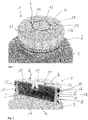
- Fig. 1 shows in a schematic view a device 1 for closing a threaded neck 2 of a container 3 (see Fig. 2 ).
- the device 1 provides tamper-evidence.
- the device 1 comprises a cap 4 and a plug 5, which is formed as a plug seal.
- the cap 4 comprises a front surface 6 and a skirt 7 surrounding the front surface 6.
- the skirt 7 comprises an inner thread 8 for engaging with a thread 9 of the threaded neck 2 of the container 3.
- the plug 5 is arranged inside the skirt 7 and the plug 5 is pressed within the neck 2 of the container 3 by the front surface 4 when the cap 4 is screwed on the threaded neck 2.
- the plug 5 comprises a top surface 16 for covering the neck 2 of the container 3.
- the front surface 6 has an inner piece 10 and an outer piece 11 that surrounds the inner piece 10.
- the inner piece 10 is connected to the outer piece 11 by four connections 12.
- the four connections between the inner piece 10 and the outer piece 11 each have a material weakening.
- connection 12 having circumferential gaps between the inner piece 10 and the outer piece 11 that surround the inner piece 10 (see Fig. 3 ).
- the gaps are bridged by the four connections forming four bridges that connect the inner piece 10 to the outer piece 11.
- the bridges extend at an angle to the radial direction of the cap 4 which is substantially 90°.
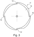
- FIG. 2 Shown in Fig. 2 is that the inner piece 10 is in mechanical engagement with the plug 5.
- the mechanical engagement allows a rotational force to be transmitted from the inner piece 10 to the plug 5.
- the inner piece 10 comprises a protrusion 13 having a circumference which is correspondingly structured to a recess 14 in the plug 5 (see Fig. 6 ).
- the inner piece 10 is a center piece and the outer piece 11 is a rim piece being connected to the skirt 7. Further, the top surface of the inner piece 10 and the top surface of the outer piece 11 are arranged in the same plane.
- the inner piece 10 is formed as a disc-shaped element.
- Fig. 2 shows that the plug 5 is in interference fit within the neck 2 of the container 3.
- the plug 5 comprises a projection 15 which extends substantially transverse to the top surface 16 and along a direction transverse to the radial direction of the plug 5.
- the projection 15 is adapted to extend into the neck 2 of the container 3 from the inside forming a plug which protrudes into the neck 2 of the container 3.
- the projection 15 is pressed against the inside of the neck 2 of the container 3.
- the plug forms an interference fit between the outer circumferential surface of the plug and the inner circumferential surface of the neck 2.
- the plug 5 comprises a further projection 17 as a sealing lip that extends substantially transverse to the top surface 16 and along a direction transverse to the radial direction of the plug 5.
- the projection 15 and the further projection 17 are substantially parallel to each other.
- the projection 17 surrounds the outer edge of the neck 2 of the container 3.
- Fig. 4 shows the steps when the container 3 with device 1 is opened for the first time.
- Fig. 4a shows the condition in which the container 3 is closed by the device 1.
- Fig. 4b shows that the cap 4 is rotated anti-clockwise and when the cap 4 is rotated anti-clockwise due to the mechanical engagement of the inner piece 10 with the plug 5 which is in interference fit within the neck 2 of the container 3, the material weakening of the connections 12 is strained and the connection 12 breaks (see Fig. 4c ).
- an inwardly extending projection 18 that supports an outer circumference 19 of the plug 5 allowing an axial force to be transmitted from the cap 4 onto the plug 5 to lift or peel the seal plug 5 from the neck 2 of the container 3.
- the inwardly extending projection 18, which can support the outer circumference 19 of the plug 5 for allowing an axial force to be transmitted from the cap 4 onto the plug 5 is spaced apart from the outer circumference 19 and in a state between closed state and opened state (second state), the extending projection 18 is in contact with the outer circumference 19.
- the cap 4 is screwed down onto the thread of the threaded neck 2 ( Fig. 5 )
- the contact between the projection 18 and the outer circumference 19 becomes lost and the projection 18 and the outer circumference 19 become spaced apart ( Fig. 2 ).
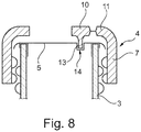
- Fig. 8 shows in a schematic view a further embodiment of a device 1 for closing a threaded neck 2 of a container 3 providing tamper-evidence in a partially cut view.
- the inner piece 10 is arranged off-center with regard to the cap 4 and the seal plug 5.
- the mechanical engagement of the inner piece 10 and the plug 5 is established by the projection 13 of the inner piece 10 extending into a recess of the plug 5.
Landscapes
- Engineering & Computer Science (AREA)
- Mechanical Engineering (AREA)
- Closures For Containers (AREA)
Abstract
The invention relates to a Device for closing a threaded neck of a container providing tamper-evidence, the device comprising a cap and a plug, wherein the cap comprises a front surface and a skirt surrounding the front surface, wherein the skirt comprises an inner thread for engaging with a thread of the threaded neck of the container, wherein the plug is at least partially arranged inside the skirt, wherein the front surface has an inner piece and an outer piece that surrounds the inner piece, wherein the inner piece is connected to the outer piece by a connection, wherein the connection between the inner piece and the outer piece has a material weakening, wherein the inner piece is in mechanical engagement with the plug, the mechanical engagement allowing a force, preferably a rotational force to be transmitted from the inner piece to the plug.
Description
- The invention relates to a device for closing a threaded neck of a container providing tamper-evidence, a container with a threaded neck comprising such a device, and the use of such a device.
- A large variety of closures for containers is known which attempt to give evidence that the container has been opened or at least has been placed in a condition for opening once it has been filled.
- A separate induction heat seal (IHS) component is known which is used to seal a container in transit and up until first use, provides tamper evidence. However, the component which is formed as an induction heat seal foil requires a step of heating during the closure of the container. A tamper indicating closure with adhesive-attached gasket is known from
US 4 747 499 A . - In other closure applications, design features such as bore seals and tamper evidence bands are used to overcome the requirement of a separate IHS component. However, in some of the known designs it is hard to identify whether the container already has been opened or not.
- Known from
US 8 596 477 B2 is a retortable package with plastic closure cap which includes a tamper-evidencing band attached to the terminal end of a skirt of the cap. The band is an extension of the skirt and/or otherwise attached to the skirt by a plurality of bridges. This design requires a certain extent of the neck of the container and the breakage of skirt and band is not necessarily evident and in that case it has to be manually verified whether the band is broken from the skirt. - It is an object of the present invention to provide a device for closing a threaded neck of a container which is improved with regard to at least one of the aforementioned issues and/or disadvantages. Further, it is an object of the present invention to improve a container comprising such a device.
- The object is solved according to the independent claims. Advantageous embodiments are the subject-matter of the dependent patent claims and/or can be gathered from the following description.
- The gist of the invention is to provide a two-part device having a plug and a cap, wherein the cap comprises a piece of the front surface which is in mechanical engagement with the cap and the mechanical engagement allows a rotational force to be transmitted from the piece to the plug. The piece of the front surface is connected to the remainder of the front surface by a material weakening. Preferably, the piece can be rotatably supported in the rotational direction in case the cap is rotated in the closing direction (usually clockwise rotation) and when the cap is rotated in the opening direction (usually anti-clockwise rotation) the piece can be broken from the remainder of the front surface by breaking along the material weakening. The material weakening can transfer a rotational force to the piece and further to the plug during the capping process, whilst in the reverse direction the material weakening can be unsupported and thus breaks on opening due to a friction of the plug on the inner neck of the container. This provides a tamper evident solution to a consumer, both visual and with an audible/physical break. The invention does not require any modification to the neck of the container. Instead, existing outer geometry of containers, especially the neck, can be maintained and most importantly no modifications are required to existing filling equipment. Further, a linerless cap can be provided. The plug can provide a leak-proof seal to the neck of the container. The plug can have a diameter which is wider than a seal usually used to ensure firm and consistent contact is maintained. Once the cap is fully applied, the thread and the front surface of the cap can provide additional pressure to maintain the seal. The container does not have to be manufactured by injection blow moulding (IBM) which is proven to achieve a container having great accuracy and consistency. Further, sealing of an extrusion blow moulded (EBM) container, especially a bottle made of HDPE or a similar material, becomes possible, which especially allows an existing dairy application to remain light-weight. However, the material is not limited to the application of HDPE but the container can also be manufactured from PET, R-PET, PP, PLA, PS or LDPE. The device can be applied to a wide range of closure applications which require sealing of products and tamper evidence without requiring additional features on the external neck to provide a locating feature for a tamper evidence band to snap over, like existing forms of closures.
- The invention provides (a) a cap and (b) a plug, wherein the cap comprises a front surface and a skirt surrounding the front surface, wherein the skirt comprises an inner thread for engaging with a thread of the threaded neck of the container, wherein the plug is at least partially arranged inside the skirt, wherein the front surface has an inner piece and an outer piece that surrounds the inner piece, wherein the inner piece is connected to the outer piece by a connection, wherein the connection between the inner piece and the outer piece has a material weakening, wherein the inner piece is in mechanical engagement with the plug, the mechanical engagement allowing a rotational force to be transmitted from the inner piece to the plug.
- The term "cap" according to the description encompasses a screw cap or closure made of plastic or metal which is screwed on and off a thread on a neck of a container. The cap can comprise continuous inner threads or lugs. The cap can be adapted to be reclosable together with the plug. The cap can further be adapted to at least partially cover the neck of a container. The cap can be adapted to be an over cap which in use can be positioned over the plug.
- The term "plug" according to the description encompasses a plug which can have a top surface and a circumferential projection or plug extending at least partially in a direction transverse to the radial direction of the top surface. The top surface can be adapted to cover an opening at the neck of the container. The circumferential projection which is in use facing the opening of the neck is adapted to be in engagement of the inner and/or outer edge of the opening at the neck of the container. The plug or circumferential projection is adapted to protrude into the neck of the container. The plug can comprise two circumferential projections extending at least partially in a direction transverse to the radial direction of the top surface, one of the two circumferential projections can be adapted to engage at least partially with the inner edge or outer edge of the neck of the container. In case two projections are provided, the other one of the two circumferential projections can be adapted to engage at least partially with the other edge of the neck of the container which is not in engagement with the first of the two projections. The plug can be adapted to be inside the cap. The plug and the cap can be manufactured separately from each other. The plug can have a maximum diameter which is greater than the inner diameter defined by the thread inside the cap. Being manufactured separately from each other, the cap and the plug can be assembled by pushing the outside rim or outer circumference of the plug behind the inner thread of the cap so that the cap and the plug remain together - the plug remains in the cap - to provide a consumer with a single unit once the device is removed from the container. In a preferred embodiment the plug can be designed as a plug seal which is adapted to seal the container, i.e. the opening at the neck of the container.
- The term "front surface" of the cap according to the description encompasses a surface which is adapted to at least partially cover the opening at the neck of the container. The front surface can be bigger than the area surrounded by the edge of the opening. The front surface can have a closed surface, but it does not necessarily have to be a closed surface. Holes, gaps and/or windows in the front surface are possible.
- The term "skirt" according to the description is a part of the cap which surrounds the front surface and extends in a direction transverse the plane of the front surface. Especially, the skirt and the front surface can confine an angle between 50° and 130°, preferably between 60° and 120°, more preferably between 70° and 110°, most preferably between 80° and 100°. In a preferred embodiment the skirt and the front surface confine an angle of substantially 90°. The skirt can be structured to increase the contact grip for manual engagement to rotate the cap in closing direction or opening direction. The skirt can have ribs extending in radial direction extending away from the center of the cap. The skirt can have a circular shape. The circular shape of the skirt can be coaxial with the front surface.
- The terms "inner piece" and "outer piece" according to the description encompass pieces of the cap which have a different distance with regard to the center of the cap which can be determined as a point in the plane of the front surface having the same distance to a circular shape defined by the skirt. The inner piece is arranged closer to the center of the cap. The distance between the outer piece and the center of the cap is greater than the distance between the inner piece and the center of the cap.
- The outer piece can be integrally formed or connected with the skirt. To increase easy handling and in order to reduce sharp edges, the connection between the outer piece and the skirt can be rounded.
- The term "material weakening" according to the description is a structural design or configuration which leads to a weakening of the material so that the inner piece can be broken from or off the outer piece. This can be done in a way that the inner piece can be rotatably supported in the rotational direction in case the cap is rotated in the closing direction and when the cap is rotated in the opening direction the inner piece is unsupported and can be broken from the remainder of the front surface breaking the material weakening.
- When it is mentioned that the inner piece is connected to the outer piece by a connection, more than one connection, i.e. 2, 3, 4, 5, 6, 7 or more connections can be possible. The connections can be arranged symmetrical around the inner piece between the inner and outer piece. The connections can be provided around the inner piece, wherein all neighboring connections with regard to the circumference can have substantially the same distance. However, an unsymmetrical arrangement of the connections can also be possible.
- The term "mechanical engagement" according to the description encompasses a contact of the inner piece with the plug that reduces a relative movement of the inner piece with regard to the plug when the cap is moved, for example rotated. In a preferred embodiment, the plug can be forced by the mechanical engagement to move together with the inner piece when rotated in the closing direction. However, the inner piece can be held static by the plug by the resistance of the plug against rotating, due to the friction against the inner neck of the container when the cap is rotated in the opening direction in this preferred embodiment. As the cap continues to rotate in the opening direction, the resistance force of the plug can be specified to be greater than the breaking strength of the material weakening at the connection between inner piece and outer piece, resulting in the connection to be broken as the cap is rotated further.
- With regard to first closure of the container, the insertion of the plug can be assisted by an existing rotational application during the filling process which can reduce the top load required to push the seal plug within the neck preventing the requirement for neck support or additional material to strengthen this area.
- Although the description refers to a detachable screw cap as a cap, the invention can also be used if the neck of the container has no thread. The cap can, for example, be lifted from the neck with a linear movement. In this respect, the cap can also be designed as a push-on cap. Alternatively or additionally, it is possible for the cap to be designed as a cap which can be lifted from the neck of the container by means of a pivoting or tilting movement. Each of the relative movements described (purely linear movement, mixed movement with a linear component, in particular tilting or pivoting movement) between the cap and the container can - in addition to or as alternative to the relative rotary movement between the cap and the container - lead to a break between the inner part and the outer part which provides a tamper evidence. For designs that work with a linear movement or a pivoting/tilting movement, it is not strictly necessary that the inner piece is in a mechanical engagement with the plug, which allows a rotational force to be transmitted from the inner piece to the plug. In these designs it can be sufficient, if a mechanical engagement between the inner piece and the plug is provided that allows for a linear force to be transmitted from the plug to the inner piece / from the inner piece to the plug.
- According to a preferred embodiment, the inner piece is a center piece and the outer piece is a rim piece. This embodiment provides an inner piece which can be in mechanical engagement with the plug at a point or an area which is arranged at a position in which the rotational force acting on the cap and the plug is reduced. Thus, the rotational force when rotating in the opening direction as well as when rotating in the closing direction can be decreased. Further, a symmetric arrangement can be provided which can be used to stabilize the inner piece and/or decrease the effort in construction and/or manufacture.
- According to a preferred embodiment, the top surface of the inner piece and the top surface of the outer piece are arranged in the same plane. This allows for a usual appearance and a simple design. In addition, the tamper evidence can be observed when looking down from above the container.
- According to a preferred embodiment, the inner piece or the plug comprises a protrusion having a circumference which is correspondingly structured to a recess in the plug or the inner piece, respectively. The protrusion extends in a direction which is transverse to the plane of the front surface. Especially, the protrusion and the front surface can confine an angle between 50° and 130°, preferably between 60° and 120°, more preferably between 70° and 110°, most preferably between 80° and 100°. In a preferred embodiment the protrusion and the front surface confine an angle of substantially 90°. A mechanical engagement of the inner piece and the plug can be insured and maintained. The mechanical engagement can be established by an interference fit, a press fit, friction fit or form fit. In a most preferred embodiment the protrusion is structured as having a non-circular outer circumference and the recess having a corresponding non-circular inner circumference to establish a form fit. The shape of the circumference of the recess can comprise abutment surfaces of the protrusion for a rotation in the opening as well as closing direction. The protrusion and the recess can be mechanically joined to obtain the mechanical engagement by means of a drive gear. The pitch of the teeth on the drive gear can be specified to aid the assembly process to maintain high levels of output by keeping alignment to a minimal. Once the seal plug is inserted into the cap being in mechanical engagement with the same, the seal plug is locked and maintained within the front surface of the cap.
- According to a preferred embodiment, the inner piece is formed as a disc-shaped element. The disc-shape of the inner piece, especially as a center piece, provides the possibility to obtain an inner piece being substantially symmetrical. The inner piece can be arranged inside the front surface with a small effort of construction and/or manufacture.
- According to a preferred embodiment, the cap comprises an inwardly extending projection that supports an outer circumference of the plug allowing an axial force to be transmitted from the cap onto the plug. The axial force can be in the same direction as the longitudinal direction of the neck and/or container. By this, the cap can be unscrewed on the neck of the container and becomes in contact with the outer circumference or rim of the plug to provide a "lifting" action away from the neck. The plug can remain in the cap.
- According to a preferred embodiment, the projection is at least partially provided by the inner thread of the cap. Providing the projection as at least partially by the inner thread of the cap, it becomes possible that the contact with the outer circumference or rim of the plug is at least partially angled with regard to the longitudinal axis of the neck or cap which can obtain a "peeling" action of the plug away from the neck.
- According to a preferred embodiment, the material weakening of the connection between the inner piece and the outer piece is provided by the thickness of the cap at the connection being thinner than the thickness of the inner piece and the outer piece. This form of material weakening is easy to construct and to design so that the breaking strength of the material weakening can be controlled in a simple manner.
- According to a preferred embodiment, the material weakening of the connection between the inner piece and the outer piece is provided by the connection having a circumferential gap between the inner piece and the outer piece that surrounds the inner piece, whereby the gap is bridged by a least one bridge that connects the inner piece to the outer piece. This form of material weakening is easy to construct and to design, too. Thus, the breaking strength of the material weakening can be controlled in a simple manner. Further, the visual appearance with regard to the purpose as a tamper evidence is simple to recognize.
- According to a preferred embodiment, the bridge extends at an angle to the radial direction. An angle to the radial direction, which can be between 50° and 130°, preferably between 60° and 120°, more preferably between 70° and 110°, most preferably between 80° and 100°, and can be in a preferred embodiment substantially 90°, offers the possibility that the material weakening can even support rotation of the inner piece in the closing direction via the outer piece when rotated, whilst in the reverse direction can be unsupported and thus break.
- When it is mentioned that the gap is bridged by at least one bridge, more than one bridge, i.e. 2, 3, 4, 5, 6, 7 or more bridges can be possible. The bridges can be arranged symmetrically at the inner piece. The bridges can be provided around the inner piece, wherein all neighboring bridges with regard to the circumference can have the same distance. However, an unsymmetrical arrangement of the bridges can also be possible.
- The invention also provides a container with a threaded neck and a device as described above which is attached to the threaded neck.
- The term "container" according to the description encompasses any receptacle or vessel, which can be especially a bottle-like, a jar-like or a tube-like container. In a preferred embodiment the container can have an extrusion blow moulded (EBM) or an injection stretch blow moulded (ISBM) neck or most preferably the container is made by extrusion blow moulding..
- According to a preferred embodiment of the container, the plug has a plug that protrudes into the neck of the container, wherein an interference fit is provided between the outer circumferential surface of the plug and the inner circumferential surface of the neck.
- According to a preferred embodiment of the container, the container is an extrusion blow moulded container.
- According to a preferred embodiment of the container, the cap comprises an inwardly extending projection that supports an outer circumference of the plug allowing an axial force to be transmitted from the cap onto the plug, wherein in a first state of the container, the extending projection is spaced apart from the outer circumference and in a second state of the container, the extending part supports the outer circumference of the plug, whereby the cap is screwed further down onto the thread of the threaded neck in the first state of the container than in the second state of the container. The distance between the projection, which can be the inner thread of the cap, and the outer circumference of the plug insures that the plug can be pushed into the neck of the container without any mechanical interaction of the cap and the plug. However, the projection still allows for a lifting or peeling action of the plug away from the neck. The projection can be at least partially formed along the inner circumference of the cap. The projection can be formed in a plane which is substantially parallel to the front surface. An inclination of the projection with regard to the front surface is preferred as the force for lifting or peeling can be initiated at a portion of the outer circumference of the plug and by further rotation of the cap the portion of the outer circumference of the plug which acts with the projection is changed and/or increased. The projection can be formed as a continuous projection or as a projection having breaks so that the projection is only formed along portions of the inner circumference of the cap.
- The invention further provides a use of a device described above to close a threaded neck of a container that contains a product, especially a dairy food product. The container with the device can establish an airtight or nearly airtight storage for the product contained therein. The airtight or nearly airtight storage can even be established after the container has been opened and closed again. The product can be sealed in the container. The device can also provide the user a tamper evidence feature to check before first opening. Applications can include chemical packaging, pharmaceutical, confectionary or any other product that may require sealing and tamper evidence within a container with a threaded neck. The product to be stored in the container can be a liquid and/or solid.
- According to the description, the term "at least partially" encompasses that the respective component can be formed completely or in part or parts along a respective indicated section.
- According to the description, the naming of a numerical value includes not only the actual numerical value, but also - in order to take into account in particular manufacturing tolerances - a range around the concrete numerical value, which can be +/- 15%, preferably +/- 10%, of the indicated numerical value.
- The description with regard to the device, especially the description with regard to similar terms used, holds for the container and the device being attached to the threaded neck of the container as well as for the described use.
- Exemplary embodiments of the invention will now be described in greater detail with reference to the drawings.
- It is shown in the drawings:
- Fig. 1
- an isometric view of a device for closing a threaded neck of a container providing tamper-evidence and a container;
- Fig. 2
- the device and the container of
Fig. 1 in partially cut view; - Fig. 3
- a detail of the device of
Fig. 1 ; - Fig. 4
- a sequence of steps when the container of
Fig. 1 is opened for the first time; - Fig. 5
- the device and the container of
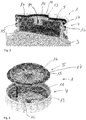
Fig. 1 in partially cut view when the container has been opened for the first time; - Fig. 6
- the device shown in
Fig.1 seen from below and before being assembled; - Fig. 7
- the device shown in
Fig. 1 in partially cut view and being assembled; and - Fig. 8
- a further embodiment of a device for closing a threaded neck of a container providing tamper-evidence in partially cut view.
-
Fig. 1 shows in a schematic view a device 1 for closing a threadedneck 2 of a container 3 (seeFig. 2 ). The device 1 provides tamper-evidence. The device 1 comprises acap 4 and aplug 5, which is formed as a plug seal. Thecap 4 comprises afront surface 6 and askirt 7 surrounding thefront surface 6. Theskirt 7 comprises aninner thread 8 for engaging with athread 9 of the threadedneck 2 of thecontainer 3. - The
plug 5 is arranged inside theskirt 7 and theplug 5 is pressed within theneck 2 of thecontainer 3 by thefront surface 4 when thecap 4 is screwed on the threadedneck 2. Theplug 5 comprises atop surface 16 for covering theneck 2 of thecontainer 3. - The
front surface 6 has aninner piece 10 and anouter piece 11 that surrounds theinner piece 10. Theinner piece 10 is connected to theouter piece 11 by fourconnections 12. The four connections between theinner piece 10 and theouter piece 11 each have a material weakening. - In the embodiment shown in
Figs. 1 to 7 , the material weakening of theconnections 12 between theinner piece 10 and theouter piece 11 is provided by theconnection 12 having circumferential gaps between theinner piece 10 and theouter piece 11 that surround the inner piece 10 (seeFig. 3 ). The gaps are bridged by the four connections forming four bridges that connect theinner piece 10 to theouter piece 11. - The bridges extend at an angle to the radial direction of the
cap 4 which is substantially 90°. - Shown in
Fig. 2 is that theinner piece 10 is in mechanical engagement with theplug 5. The mechanical engagement allows a rotational force to be transmitted from theinner piece 10 to theplug 5. - The
inner piece 10 comprises aprotrusion 13 having a circumference which is correspondingly structured to arecess 14 in the plug 5 (seeFig. 6 ). - In the embodiment shown in
Figs. 1 to 7 , theinner piece 10 is a center piece and theouter piece 11 is a rim piece being connected to theskirt 7. Further, the top surface of theinner piece 10 and the top surface of theouter piece 11 are arranged in the same plane. - As can be seen from
Fig. 3 theinner piece 10 is formed as a disc-shaped element. -
Fig. 2 shows that theplug 5 is in interference fit within theneck 2 of thecontainer 3. Theplug 5 comprises aprojection 15 which extends substantially transverse to thetop surface 16 and along a direction transverse to the radial direction of theplug 5. Theprojection 15 is adapted to extend into theneck 2 of thecontainer 3 from the inside forming a plug which protrudes into theneck 2 of thecontainer 3. Theprojection 15 is pressed against the inside of theneck 2 of thecontainer 3. The plug forms an interference fit between the outer circumferential surface of the plug and the inner circumferential surface of theneck 2. - The
plug 5 comprises afurther projection 17 as a sealing lip that extends substantially transverse to thetop surface 16 and along a direction transverse to the radial direction of theplug 5. Theprojection 15 and thefurther projection 17 are substantially parallel to each other. Theprojection 17 surrounds the outer edge of theneck 2 of thecontainer 3. -
Fig. 4 shows the steps when thecontainer 3 with device 1 is opened for the first time.Fig. 4a shows the condition in which thecontainer 3 is closed by the device 1.Fig. 4b shows that thecap 4 is rotated anti-clockwise and when thecap 4 is rotated anti-clockwise due to the mechanical engagement of theinner piece 10 with theplug 5 which is in interference fit within theneck 2 of thecontainer 3, the material weakening of theconnections 12 is strained and theconnection 12 breaks (seeFig. 4c ). - Formed by a section of the
inner thread 8 of thecap 4 is an inwardly extendingprojection 18 that supports anouter circumference 19 of theplug 5 allowing an axial force to be transmitted from thecap 4 onto theplug 5 to lift or peel theseal plug 5 from theneck 2 of thecontainer 3. In the closed state (first state) of thecontainer 3, the inwardly extendingprojection 18, which can support theouter circumference 19 of theplug 5 for allowing an axial force to be transmitted from thecap 4 onto theplug 5, is spaced apart from theouter circumference 19 and in a state between closed state and opened state (second state), the extendingprojection 18 is in contact with theouter circumference 19. Vice versa, when thecap 4 is screwed down onto the thread of the threaded neck 2 (Fig. 5 ), the contact between theprojection 18 and theouter circumference 19 becomes lost and theprojection 18 and theouter circumference 19 become spaced apart (Fig. 2 ). -
Fig. 8 shows in a schematic view a further embodiment of a device 1 for closing a threadedneck 2 of acontainer 3 providing tamper-evidence in a partially cut view. Theinner piece 10 is arranged off-center with regard to thecap 4 and theseal plug 5. The mechanical engagement of theinner piece 10 and theplug 5 is established by theprojection 13 of theinner piece 10 extending into a recess of theplug 5.
Claims (15)
- Device (1) for closing a threaded neck (2) of a container (3) providing tamper-evidence, the device (1) comprising(a) a cap (4) and(b) a plug (5),wherein the cap (4) comprises a front surface (6) and a skirt (7) surrounding the front surface (6), wherein the skirt (7) comprises an inner thread (8) for engaging with a thread of the threaded neck (2) of the container (3),
wherein the plug (5) is at least partially arranged inside the skirt (7),
wherein the front surface (6) has an inner piece (10) and an outer piece (11) that surrounds the inner piece (10), wherein the inner piece (10) is connected to the outer piece (11) by a connection (12), wherein the connection (12) between the inner piece (10) and the outer piece (11) has a material weakening,
wherein the inner piece (10) is in mechanical engagement with the plug (5), the mechanical engagement allowing a force, preferably a rotational force to be transmitted from the inner piece (10) to the plug (5). - Device (1) according to claim 1, wherein the inner piece (10) is a center piece and the outer piece (11) is a rim piece.
- Device (1) according to claim 1 or 2, wherein the top surface of the inner piece (10) and the top surface of the outer piece (11) are arranged in the same plane.
- Device (1) according to any one of claims 1 to 3, wherein the inner piece (10) or the plug (5) comprises a protrusion (13) having a circumference which is correspondingly structured to a recess (14) in the plug (5) or the inner piece (10), respectively.
- Device (1) according to any one of claims 1 to 4, wherein the inner piece (10) is formed as a disc-shaped element.
- Device (1) according to any one of claims 1 to 5, wherein the cap (4) comprises an inwardly extending projection (18) that supports an outer circumference (19) of the plug (5) allowing an axial force to be transmitted from the cap (4) onto the plug (5).
- Device (1) according to claim 6, wherein the projection (18) is at least partially provided by the inner thread (8) of the cap (4).
- Device (1) according to any one of claims 1 to 7, wherein the material weakening of the connection (12) between the inner piece (10) and the outer piece (11) is provided by the thickness of the cap (4) at the connection (12) being thinner than the thickness of the inner piece (10) and the outer piece (11).
- Device (1) according to any one of claims 1 to 7, wherein the material weakening of the connection (12) between the inner piece (10) and the outer piece (11) is provided
by the connection (12) having a circumferential gap between the inner piece (10) and the outer piece (11) that surrounds the inner piece (10), whereby the gap is bridged by a least one bridge that connects the inner piece (10) to the outer piece (11). - Device (1) according to claim 9, characterized in that the bridge extends at an angle to the radial direction.
- Container (3) with a threaded neck (2) and a device (1) according to any one of claims 1 to 10 being attached to the threaded neck (2).
- Container (3) according to claim 11, wherein the plug (5) has a plug that protrudes into the neck (2) of the container (3), wherein an interference fit is provided between the outer circumferential surface of the plug and the inner circumferential surface of the neck (2).
- Container (3) according to one of claims 11 and 12, wherein the container (3) is an extrusion blow moulded container.
- Container (3) according to any one of claims 11 to 13, wherein the cap (4) comprises an inwardly extending projection (18) that supports an outer circumference (19) of the plug (5) allowing an axial force to be transmitted from the cap (4) onto the plug (5), wherein in a first state of the container (3), the extending projection (18) is spaced apart from the outer circumference (19) and in a second state of the container (3), the inwardly extending projection (18) supports the outer circumference (19) of the plug (5), whereby the cap (4) is screwed further down onto the thread of the threaded neck (2) in the first state of the container (3) than in the second state of the container (3).
- Use of a device (1) according to any one of claims 1 to 10 to close a threaded neck (2) of a container (3) that contains a product which requires sealing, especially a dairy product.
Priority Applications (5)
| Application Number | Priority Date | Filing Date | Title |
|---|---|---|---|
| EP19188510.2A EP3770079A1 (en) | 2019-07-26 | 2019-07-26 | Device for closing a threaded neck of a container providing tamper-evidence |
| PCT/EP2020/070766 WO2021018716A1 (en) | 2019-07-26 | 2020-07-23 | Device for closing a threaded neck of a container providing tamper-evidence |
| US17/627,718 US20220250813A1 (en) | 2019-07-26 | 2020-07-23 | Device for closing a threaded neck of a container providing tamper-evidence |
| EP20743144.6A EP4003863A1 (en) | 2019-07-26 | 2020-07-23 | Device for closing a threaded neck of a container providing tamper-evidence |
| CA3143769A CA3143769A1 (en) | 2019-07-26 | 2020-07-23 | Device for closing a threaded neck of a container providing tamper-evidence |
Applications Claiming Priority (1)
| Application Number | Priority Date | Filing Date | Title |
|---|---|---|---|
| EP19188510.2A EP3770079A1 (en) | 2019-07-26 | 2019-07-26 | Device for closing a threaded neck of a container providing tamper-evidence |
Publications (1)
| Publication Number | Publication Date |
|---|---|
| EP3770079A1 true EP3770079A1 (en) | 2021-01-27 |
Family
ID=67439025
Family Applications (2)
| Application Number | Title | Priority Date | Filing Date |
|---|---|---|---|
| EP19188510.2A Withdrawn EP3770079A1 (en) | 2019-07-26 | 2019-07-26 | Device for closing a threaded neck of a container providing tamper-evidence |
| EP20743144.6A Withdrawn EP4003863A1 (en) | 2019-07-26 | 2020-07-23 | Device for closing a threaded neck of a container providing tamper-evidence |
Family Applications After (1)
| Application Number | Title | Priority Date | Filing Date |
|---|---|---|---|
| EP20743144.6A Withdrawn EP4003863A1 (en) | 2019-07-26 | 2020-07-23 | Device for closing a threaded neck of a container providing tamper-evidence |
Country Status (4)
| Country | Link |
|---|---|
| US (1) | US20220250813A1 (en) |
| EP (2) | EP3770079A1 (en) |
| CA (1) | CA3143769A1 (en) |
| WO (1) | WO2021018716A1 (en) |
Citations (7)
| Publication number | Priority date | Publication date | Assignee | Title |
|---|---|---|---|---|
| US4378894A (en) * | 1981-06-19 | 1983-04-05 | Aluminum Company Of America | Tamper-evident closure |
| US4747499A (en) | 1983-02-14 | 1988-05-31 | Sunbeam Plastics Corporation | Tamper indicating closure with adhesive-attached gasket |
| US4801029A (en) * | 1988-02-09 | 1989-01-31 | Continental White Cap, Inc. | Tamper evident cap |
| US5975322A (en) * | 1995-04-12 | 1999-11-02 | Innovative Molding | Wine bottle closure with threads |
| US20090032488A1 (en) * | 2007-07-30 | 2009-02-05 | Owens-Illinois Closure Inc. | Ceremonial plug closure and package |
| US8596477B2 (en) | 2005-12-28 | 2013-12-03 | Silgan White Cap LLC | Retortable package with plastic closure cap |
| WO2018136927A1 (en) * | 2017-01-23 | 2018-07-26 | Rieke Corporation | Closure for container with informational and/or anti-counterfeiting capabilities |
Family Cites Families (3)
| Publication number | Priority date | Publication date | Assignee | Title |
|---|---|---|---|---|
| US5660290A (en) * | 1996-03-27 | 1997-08-26 | Carnaudmetalbox (Holdings) Usa Inc. | Closure fitting for unthreaded containers |
| US5960972A (en) * | 1996-11-15 | 1999-10-05 | Constancio Larguia, Sr. | Container cap with interlocked safety closure |
| US7780024B1 (en) * | 2005-07-14 | 2010-08-24 | Rexam Closures And Containers Inc. | Self peel flick-it seal for an opening in a container neck |
-
2019
- 2019-07-26 EP EP19188510.2A patent/EP3770079A1/en not_active Withdrawn
-
2020
- 2020-07-23 EP EP20743144.6A patent/EP4003863A1/en not_active Withdrawn
- 2020-07-23 WO PCT/EP2020/070766 patent/WO2021018716A1/en unknown
- 2020-07-23 US US17/627,718 patent/US20220250813A1/en not_active Abandoned
- 2020-07-23 CA CA3143769A patent/CA3143769A1/en active Pending
Patent Citations (7)
| Publication number | Priority date | Publication date | Assignee | Title |
|---|---|---|---|---|
| US4378894A (en) * | 1981-06-19 | 1983-04-05 | Aluminum Company Of America | Tamper-evident closure |
| US4747499A (en) | 1983-02-14 | 1988-05-31 | Sunbeam Plastics Corporation | Tamper indicating closure with adhesive-attached gasket |
| US4801029A (en) * | 1988-02-09 | 1989-01-31 | Continental White Cap, Inc. | Tamper evident cap |
| US5975322A (en) * | 1995-04-12 | 1999-11-02 | Innovative Molding | Wine bottle closure with threads |
| US8596477B2 (en) | 2005-12-28 | 2013-12-03 | Silgan White Cap LLC | Retortable package with plastic closure cap |
| US20090032488A1 (en) * | 2007-07-30 | 2009-02-05 | Owens-Illinois Closure Inc. | Ceremonial plug closure and package |
| WO2018136927A1 (en) * | 2017-01-23 | 2018-07-26 | Rieke Corporation | Closure for container with informational and/or anti-counterfeiting capabilities |
Also Published As
| Publication number | Publication date |
|---|---|
| EP4003863A1 (en) | 2022-06-01 |
| US20220250813A1 (en) | 2022-08-11 |
| WO2021018716A1 (en) | 2021-02-04 |
| CA3143769A1 (en) | 2021-02-04 |
Similar Documents
| Publication | Publication Date | Title |
|---|---|---|
| CA1321567C (en) | Rigid container, particularly of glass, having a screw closure device | |
| CA1294585C (en) | Combination of endpiece and recipient | |
| EP1582475B1 (en) | Tamper evident closure assembly | |
| US8123056B2 (en) | Closure arrangement with opening indicating (anti-tamper) elements | |
| US11577887B2 (en) | Closure with tamper-evident band | |
| KR20150016975A (en) | Closure with application guide | |
| US8544666B2 (en) | Tamper-evident container system | |
| US4898295A (en) | Spin welded, tamper-proof, resealable thermoplastic container | |
| CA2428077A1 (en) | Synthetic-resin screw cap | |
| EP3102501B1 (en) | Container closure | |
| JP6715580B2 (en) | Container mouth structure and container | |
| US9758283B2 (en) | Measuring cap | |
| US20180319550A1 (en) | Single-Thread Screw Thread Variator Device | |
| CN107000903B (en) | For the lid of container and the packaging including such lid | |
| US20220250813A1 (en) | Device for closing a threaded neck of a container providing tamper-evidence | |
| CN110615174A (en) | Packaging container with safety reminding structure | |
| JP4928625B2 (en) | Container with opening means | |
| CN113853342B (en) | Closure for a container | |
| JP6702020B2 (en) | Cap structure and packaging container using the same | |
| EP1627821A1 (en) | Screw cap for a container | |
| GB2307901A (en) | Child-resistant and tamper-evident screw closure | |
| US12122575B2 (en) | Closing cap for a container | |
| US20230399149A1 (en) | Closure cap and container neck for preventing detachment of a tamperevident strip | |
| EP4206083B1 (en) | Container | |
| EP3608244B1 (en) | Metal container with closure |
Legal Events
| Date | Code | Title | Description |
|---|---|---|---|
| PUAI | Public reference made under article 153(3) epc to a published international application that has entered the european phase |
Free format text: ORIGINAL CODE: 0009012 |
|
| STAA | Information on the status of an ep patent application or granted ep patent |
Free format text: STATUS: THE APPLICATION HAS BEEN PUBLISHED |
|
| AK | Designated contracting states |
Kind code of ref document: A1 Designated state(s): AL AT BE BG CH CY CZ DE DK EE ES FI FR GB GR HR HU IE IS IT LI LT LU LV MC MK MT NL NO PL PT RO RS SE SI SK SM TR |
|
| AX | Request for extension of the european patent |
Extension state: BA ME |
|
| STAA | Information on the status of an ep patent application or granted ep patent |
Free format text: STATUS: THE APPLICATION IS DEEMED TO BE WITHDRAWN |
|
| 18D | Application deemed to be withdrawn |
Effective date: 20210728 |