EP3769988A1 - Kühlkreislauf - Google Patents
Kühlkreislauf Download PDFInfo
- Publication number
- EP3769988A1 EP3769988A1 EP20182284.8A EP20182284A EP3769988A1 EP 3769988 A1 EP3769988 A1 EP 3769988A1 EP 20182284 A EP20182284 A EP 20182284A EP 3769988 A1 EP3769988 A1 EP 3769988A1
- Authority
- EP
- European Patent Office
- Prior art keywords
- cooling circuit
- volume flow
- partial
- electrical machine
- motor vehicle
- Prior art date
- Legal status (The legal status is an assumption and is not a legal conclusion. Google has not performed a legal analysis and makes no representation as to the accuracy of the status listed.)
- Granted
Links
Images
Classifications
-
- B—PERFORMING OPERATIONS; TRANSPORTING
- B60—VEHICLES IN GENERAL
- B60K—ARRANGEMENT OR MOUNTING OF PROPULSION UNITS OR OF TRANSMISSIONS IN VEHICLES; ARRANGEMENT OR MOUNTING OF PLURAL DIVERSE PRIME-MOVERS IN VEHICLES; AUXILIARY DRIVES FOR VEHICLES; INSTRUMENTATION OR DASHBOARDS FOR VEHICLES; ARRANGEMENTS IN CONNECTION WITH COOLING, AIR INTAKE, GAS EXHAUST OR FUEL SUPPLY OF PROPULSION UNITS IN VEHICLES
- B60K1/00—Arrangement or mounting of electrical propulsion units
-
- B—PERFORMING OPERATIONS; TRANSPORTING
- B60—VEHICLES IN GENERAL
- B60K—ARRANGEMENT OR MOUNTING OF PROPULSION UNITS OR OF TRANSMISSIONS IN VEHICLES; ARRANGEMENT OR MOUNTING OF PLURAL DIVERSE PRIME-MOVERS IN VEHICLES; AUXILIARY DRIVES FOR VEHICLES; INSTRUMENTATION OR DASHBOARDS FOR VEHICLES; ARRANGEMENTS IN CONNECTION WITH COOLING, AIR INTAKE, GAS EXHAUST OR FUEL SUPPLY OF PROPULSION UNITS IN VEHICLES
- B60K11/00—Arrangement in connection with cooling of propulsion units
- B60K11/02—Arrangement in connection with cooling of propulsion units with liquid cooling
-
- B—PERFORMING OPERATIONS; TRANSPORTING
- B60—VEHICLES IN GENERAL
- B60K—ARRANGEMENT OR MOUNTING OF PROPULSION UNITS OR OF TRANSMISSIONS IN VEHICLES; ARRANGEMENT OR MOUNTING OF PLURAL DIVERSE PRIME-MOVERS IN VEHICLES; AUXILIARY DRIVES FOR VEHICLES; INSTRUMENTATION OR DASHBOARDS FOR VEHICLES; ARRANGEMENTS IN CONNECTION WITH COOLING, AIR INTAKE, GAS EXHAUST OR FUEL SUPPLY OF PROPULSION UNITS IN VEHICLES
- B60K6/00—Arrangement or mounting of plural diverse prime-movers for mutual or common propulsion, e.g. hybrid propulsion systems comprising electric motors and internal combustion engines
- B60K6/20—Arrangement or mounting of plural diverse prime-movers for mutual or common propulsion, e.g. hybrid propulsion systems comprising electric motors and internal combustion engines the prime-movers consisting of electric motors and internal combustion engines, e.g. HEVs
- B60K6/50—Architecture of the driveline characterised by arrangement or kind of transmission units
- B60K6/52—Driving a plurality of drive axles, e.g. four-wheel drive
-
- B—PERFORMING OPERATIONS; TRANSPORTING
- B60—VEHICLES IN GENERAL
- B60L—PROPULSION OF ELECTRICALLY-PROPELLED VEHICLES; SUPPLYING ELECTRIC POWER FOR AUXILIARY EQUIPMENT OF ELECTRICALLY-PROPELLED VEHICLES; ELECTRODYNAMIC BRAKE SYSTEMS FOR VEHICLES IN GENERAL; MAGNETIC SUSPENSION OR LEVITATION FOR VEHICLES; MONITORING OPERATING VARIABLES OF ELECTRICALLY-PROPELLED VEHICLES; ELECTRIC SAFETY DEVICES FOR ELECTRICALLY-PROPELLED VEHICLES
- B60L50/00—Electric propulsion with power supplied within the vehicle
- B60L50/50—Electric propulsion with power supplied within the vehicle using propulsion power supplied by batteries or fuel cells
- B60L50/60—Electric propulsion with power supplied within the vehicle using propulsion power supplied by batteries or fuel cells using power supplied by batteries
-
- B—PERFORMING OPERATIONS; TRANSPORTING
- B60—VEHICLES IN GENERAL
- B60K—ARRANGEMENT OR MOUNTING OF PROPULSION UNITS OR OF TRANSMISSIONS IN VEHICLES; ARRANGEMENT OR MOUNTING OF PLURAL DIVERSE PRIME-MOVERS IN VEHICLES; AUXILIARY DRIVES FOR VEHICLES; INSTRUMENTATION OR DASHBOARDS FOR VEHICLES; ARRANGEMENTS IN CONNECTION WITH COOLING, AIR INTAKE, GAS EXHAUST OR FUEL SUPPLY OF PROPULSION UNITS IN VEHICLES
- B60K1/00—Arrangement or mounting of electrical propulsion units
- B60K2001/003—Arrangement or mounting of electrical propulsion units with means for cooling the electrical propulsion units
- B60K2001/006—Arrangement or mounting of electrical propulsion units with means for cooling the electrical propulsion units the electric motors
-
- Y—GENERAL TAGGING OF NEW TECHNOLOGICAL DEVELOPMENTS; GENERAL TAGGING OF CROSS-SECTIONAL TECHNOLOGIES SPANNING OVER SEVERAL SECTIONS OF THE IPC; TECHNICAL SUBJECTS COVERED BY FORMER USPC CROSS-REFERENCE ART COLLECTIONS [XRACs] AND DIGESTS
- Y02—TECHNOLOGIES OR APPLICATIONS FOR MITIGATION OR ADAPTATION AGAINST CLIMATE CHANGE
- Y02T—CLIMATE CHANGE MITIGATION TECHNOLOGIES RELATED TO TRANSPORTATION
- Y02T10/00—Road transport of goods or passengers
- Y02T10/60—Other road transportation technologies with climate change mitigation effect
- Y02T10/70—Energy storage systems for electromobility, e.g. batteries
Definitions
- the invention relates to a cooling circuit for a drive train of a motor vehicle, the drive train having at least one first electrical machine for providing a first drive power for a first axle of the motor vehicle and at least one second electrical machine for providing a second drive power for a second axle of the motor vehicle.
- the cooling circuit is intended in particular for temperature control of (electrical) components of a motor vehicle.
- Motor vehicles have one or more cooling circuits in which a cooling fluid is conveyed through the cooling circuit by one or more pumps (each).
- a cooling fluid is conveyed through the cooling circuit by one or more pumps (each).
- thermal energy is absorbed via the cooling fluid by the components integrated in the respective cooling circuit, in particular an electrical machine, a pulse-controlled inverter, a charger, a voltage converter, a battery. This thermal energy is then released into the ambient air via an ambient heat exchanger (a cooler).
- a cooling arrangement for a motor vehicle is known.
- a friction clutch and an electrical machine are cooled by a pump arrangement.
- the cooling capacity can be freely regulated between 0% and 100% for both components.
- cooling circuits should be constructed as simply as possible and be operated with low energy consumption.
- the object of the present invention is to at least partially solve the problems cited with reference to the prior art.
- a cooling circuit is to be specified which is designed as simply as possible, especially for motor vehicles with all-wheel drive, and which can be operated with low energy consumption.
- a cooling circuit for a drive train of a motor vehicle having at least one first electrical machine for providing a first drive power for a first axle of the motor vehicle and at least one second electrical machine for providing a second drive power for a second axle of the motor vehicle.
- the cooling circuit has at least one pump for conveying a cooling fluid through the cooling circuit, at least the first electrical machine and the second electrical machine being arranged in subregions of the cooling circuit that are connected in parallel to one another.
- the cooling circuit is provided for a drive train by means of which an all-wheel drive can be implemented.
- the electrical machines are each assigned to (only) one axis.
- At least one electrical machine is only operated as required.
- a switchable all-wheel drive is implemented in this way.
- the cooling circuit can have one or more pumps, which can be operated individually or jointly to represent volume flows of different sizes. However, the at least one pump only generates a (common) volume flow that can be conveyed through the cooling circuit.
- the volume flow downstream of the at least one pump is divided into a first sub-area and a second sub-area, which are connected in parallel to one another. Downstream of the partial areas, the partial volume flows of the partial areas are brought together again. In particular, the then common volume flow can act on a cooler (an ambient heat exchanger) so that the absorbed thermal energy can be dissipated to an environment.
- a cooler an ambient heat exchanger
- a bypass to bypass the cooler is provided for the (total) volume flow, so that, for. B. a preferred operating temperature of the cooling fluid can be reached faster after starting a cooling circuit.
- the diversion of the cooling fluid to the cooler or to the bypass can take place via a valve (e.g. a 2-way valve).
- a battery (a power store provided for the electrical supply of at least both electrical machines) can be acted upon by the volume flow.
- the battery can have its own partial cooling circuit (e.g. with its own pump) acted upon with the cooling fluid at least temporarily in order to also heat or temper the battery more quickly to a preferred operating temperature.
- an expansion tank is connected to the cooling circuit.
- the expansion tank ensures that there is sufficient cooling fluid in the cooling circuit.
- An expansion of the cooling fluid can also be compensated for by means of an air reservoir via the expansion tank.
- a volume flow conveyed by the at least one pump is divided in a predetermined ratio into a first partial volume flow for a first partial area and a second partial volume flow for a second partial area of the cooling circuit via at least one throttle.
- a throttle is a particularly constant cross-sectional constriction of a flow cross-section (here the flow cross-section of at least one of the subregions).
- a ratio between the first partial volume flow and the second partial volume flow (fixed) can be set with the throttle.
- the at least one throttle is arranged in the second partial area so that the second partial volume flow acting on the second partial area is (always) smaller than the first partial volume flow.
- the second sub-area is assigned to the electrical machine, which is only used as required (for example when all-wheel drive is to be provided) to drive the motor vehicle.
- the second partial area is therefore only acted upon by a second partial volume flow when required.
- there is always a second partial volume flow when the drive train is in operation since a pulse-controlled inverter assigned to this electrical machine always requires heat dissipation.
- a volume flow conveyed by the at least one pump can be divided in a variable ratio into a first partial volume flow for a first partial area and a second partial volume flow for a second partial area of the cooling circuit via at least one control valve.
- control valve can reduce at least the second partial volume flow to zero.
- control valve can also reduce the first partial volume flow to zero.
- each ratio of the partial volume flows can be set via the control valve.
- each partial volume flow can be between 0% and 100% of the volume flow delivered by the at least one pump.
- the motor vehicle is driven via the first drive power, the second drive power only being able to be provided in addition to the first drive power when required.
- a pulse-controlled inverter is arranged in each sub-area.
- the pulse-controlled inverter is arranged in at least one of the partial areas (preferably in both partial areas) upstream of the electrical machine arranged in the partial area.
- further components of the drive train are arranged in the first partial area or in the area of the cooling circuit through which the (total) volume flow flows (for example a charger and / or a voltage converter).
- a motor vehicle is also proposed, at least having a drive train.
- the drive train comprises at least one first electrical machine for providing a first drive power for a first axle (with wheels) of the motor vehicle and at least one second electrical machine for providing a second drive power for a second axle (with wheels) of the motor vehicle. Both electrical machines are arranged in the cooling circuit described.
- first primarily (only) serve to distinguish between several similar objects, sizes or processes, i.e. in particular no dependency and / or sequence of these objects, Specify sizes or processes for each other. Should a dependency and / or sequence be required, this is explicitly stated here or it is obvious to the person skilled in the art when studying the specifically described embodiment. If a component can occur several times (“at least one"), the description of one of these components can apply equally to all or part of the majority of these components, but this is not mandatory.
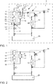
- the Fig. 1 shows a motor vehicle 3 with a drive train 2 and a first variant of a cooling circuit 1.
- the drive train 2 comprises a first electrical machine 4 for providing a first drive power for a first axle 5 with wheels of the motor vehicle 3 and a second electrical machine 6 for providing a second Drive power for a second axle 7 with wheels of the motor vehicle 3.
- Both electrical machines 4, 6 are arranged in a cooling circuit 1 or are acted upon by cooling fluid 9 through one cooling circuit 1.
- the cooling circuit 1 has a pump 8 for conveying a cooling fluid 9 through the cooling circuit 1, at least the first electrical machine 4 and the second electrical machine 6 being arranged in subregions 10, 11 of the cooling circuit 1 connected in parallel to one another.
- the cooling circuit 1 is provided for a drive train 2 by means of which an all-wheel drive can be implemented.
- the electrical machines 4, 6 are each assigned to only one axis 4, 6, so they can only provide the drive power generated to this one axis.
- the volume flow 12 generated by the pump 8 is divided downstream of the pump 8 into a first sub-area 10 and a second sub-area 11, which are connected in parallel to one another. Downstream of the partial areas 10, 11, the partial volume flows 14, 15 of the partial areas 10, 11 are brought together again.
- a cooler 22 an ambient heat exchanger
- a bypass 23 is provided to bypass the cooler 22 so that, for. B. after starting up a cooling circuit 1, a preferred operating temperature of the cooling fluid 9 can be reached more quickly.
- the diversion of the cooling fluid 9 to the cooler 22 or to the bypass 23 takes place via a valve 21 (e.g. a 2/3-way valve; with two switching positions and three connections).
- a battery 25 can be acted upon by the volume flow 12.
- An expansion tank 24 is also connected to the cooling circuit 1.
- the expansion tank 24 ensures that there is sufficient cooling fluid 9 in the cooling circuit 1. Furthermore, expansion of the cooling fluid 9 can be compensated for by means of an air reservoir via the expansion tank 24.
- the volume flow 12 conveyed by the pump 8 can be divided in a predetermined ratio into a first partial volume flow 14 for a first partial area 10 and a second partial volume flow 15 for a second partial area 11 of the cooling circuit 1 via a throttle 13.
- the throttle 13 is arranged in the second partial area 11, so that the second partial volume flow 15 acting on the second partial area 11 is (always) smaller than the first partial volume flow 14.
- the second sub-area 11 is assigned to the second electrical machine 6, which is only switched on as required (for example when all-wheel drive is to be provided).
- the motor vehicle 3 is driven via the first drive power, the second drive power only being able to be provided in addition to the first drive power when required.
- Only components 17 (for example only one pulse-controlled inverter 18 - PWR) that are required for operating the second electrical machine 6 are arranged in the second partial area 11.
- the pulse-controlled inverters 18 are arranged in both sub-areas upstream of the electrical machine 4, 6 arranged in the sub-area 10, 11. In this way, the pulse-controlled inverter 18 can each have a cooler cooling fluid 9 applied to it than the electrical machines 4, 6.
- further components 17 of the drive train 2 are arranged (here along the flow direction of the cooling fluid 9, for example, a voltage converter 20 and then a charger 19).
- Fig. 2 shows a second variant embodiment of a cooling circuit 1 Fig. 1 is referred.
- the cooling circuit 1 here has a control valve 16 (instead of the throttle 13), via which a volume flow 12 conveyed by the pump 8 in a variable ratio into a first partial volume flow 14 for a first partial area 10 and into a second partial volume flow 15 can be divided for a second sub-area 11 of the cooling circuit 1.
- the control valve 16 can reduce both the second partial volume flow 15 and the first partial volume flow 14 to zero. Any ratio of the partial volume flows 14, 15 can be set via the control valve 16. In particular, each partial volume flow 14, 15 can be between 0% and 100% of the volume flow 12 conveyed by the pump 8.
- control valve 16 is designed as a proportional valve, a slide being adjustable as required.
Landscapes
- Engineering & Computer Science (AREA)
- Transportation (AREA)
- Mechanical Engineering (AREA)
- Chemical & Material Sciences (AREA)
- Combustion & Propulsion (AREA)
- Life Sciences & Earth Sciences (AREA)
- Sustainable Development (AREA)
- Sustainable Energy (AREA)
- Power Engineering (AREA)
- Electric Propulsion And Braking For Vehicles (AREA)
Abstract
Description
- Die Erfindung betrifft einen Kühlkreislauf für einen Antriebsstrang eines Kraftfahrzeugs, wobei der Antriebsstrang zumindest eine erste elektrische Maschine zur Bereitstellung einer ersten Antriebsleistung für eine erste Achse des Kraftfahrzeuges und zumindest eine zweite elektrische Maschine zur Bereitstellung einer zweiten Antriebsleistung für eine zweite Achse des Kraftfahrzeuges aufweist. Das Kühlkreislauf ist insbesondere zur Temperierung von (elektrischen) Komponenten eines Kraftfahrzeuges vorgesehen.
- Kraftfahrzeuge weisen ein oder mehrere Kühlkreisläufe auf, in denen ein Kühlfluid durch eine oder mehrere Pumpen (jeweils) durch den Kühlkreislauf gefördert wird. Dabei wird über das Kühlfluid Wärmeenergie von den, in dem jeweiligen Kühlkreislauf integrierten Komponenten, insbesondere einer elektrischen Maschine, einem Pulswechselgleichrichter, einem Ladegerät, einem Spannungswandler, einer Batterie, aufgenommen. Diese Wärmeenergie wird anschließend über einen Umgebungswärmetauscher (einem Kühler) an die Umgebungsluft abgegeben.
- Es ist bekannt, insbesondere für jede Antriebseinheit eines Kraftfahrzeugs jeweils einen eigenen Kühlkreislauf mit einer eigenen Pumpe bereitzustellen. Dabei kann die Kühlung jeder Antriebseinheit und die ihr zugeordneten Komponenten über die jeweilige Pumpe geregelt erfolgen.
- Aus der
EP 2 667 053 B1 ist eine Kühlanordnung für ein Kraftfahrzeug bekannt. Dabei wird über eine Pumpenanordnung eine Reibungskupplung und eine elektrische Maschine gekühlt. Die Kühlleistung kann für beide Komponenten zwischen jeweils 0% und 100% frei geregelt werden. - Es besteht ein ständiges Bedürfnis, vorhandene Kühlkreisläufe bzw. Antriebsstränge zu verbessern. Insbesondere sollen Kühlkreisläufe möglichst einfach aufgebaut und energetisch günstig zu betreiben sein.
- Aufgabe der vorliegenden Erfindung ist es, die mit Bezug auf den Stand der Technik angeführten Probleme zumindest teilweise zu lösen. Insbesondere soll ein Kühlkreislauf angegeben werden, der gerade für Kraftfahrzeuge mit Allradantrieb möglichst einfach ausgeführt ist und energetisch günstig betreibbar ist.
- Zur Lösung dieser Aufgaben trägt ein Kühlkreislauf mit den Merkmalen gemäß Patentanspruch 1 bei. Vorteilhafte Weiterbildungen sind Gegenstand der abhängigen Patentansprüche. Die in den Patentansprüchen einzeln aufgeführten Merkmale sind in technologisch sinnvoller Weise miteinander kombinierbar und können durch erläuternde Sachverhalte aus der Beschreibung und/oder Details aus den Figuren ergänzt werden, wobei weitere Ausführungsvarianten der Erfindung aufgezeigt werden.
- Es wird ein Kühlkreislauf für einen Antriebsstrang eines Kraftfahrzeugs vorgeschlagen, wobei der Antriebsstrang zumindest eine erste elektrische Maschine zur Bereitstellung einer ersten Antriebsleistung für eine erste Achse des Kraftfahrzeuges und zumindest eine zweite elektrische Maschine zur Bereitstellung einer zweiten Antriebsleistung für eine zweite Achse des Kraftfahrzeuges aufweist. Der Kühlkreislauf weist mindestens eine Pumpe zur Förderung eines Kühlfluids durch den Kühlkreislauf auf, wobei zumindest die erste elektrische Maschine und die zweite elektrische Maschine in zueinander parallel geschalteten Teilbereichen des Kühlkreislaufs angeordnet sind.
- Insbesondere ist der Kühlkreislauf für einen Antriebsstrang vorgesehen, durch den ein Allradantrieb realisierbar ist. Insbesondere sind die elektrischen Maschinen jeweils (nur) einer Achse zugeordnet.
- Insbesondere ist vorgesehen, dass zumindest eine elektrische Maschine nur bedarfsweise betrieben wird. Damit ist insbesondere ein zuschaltbarer Allradantrieb realisiert.
- Der Kühlkreislauf kann eine oder mehrere Pumpen aufweisen, die zur Darstellung unterschiedlich großer Volumenströme jeweils allein oder gemeinsam betreibbar sein können. Allerdings erzeugt die mindestens eine Pumpe nur einen (gemeinsamen) Volumenstrom, der durch den Kühlkreislauf gefördert werden kann.
- Insbesondere wird der Volumenstrom stromabwärts der mindestens einen Pumpe aufgeteilt in einen ersten Teilbereich und in einen zweiten Teilbereich, die zueinander parallel verschaltet sind. Stromabwärts der Teilbereiche werden die Teilvolumenströme der Teilbereiche wieder zusammengeführt. Insbesondere kann durch den dann gemeinsamen Volumenstrom ein Kühler (ein Umgebungswärmetauscher) beaufschlagt werden, so dass die aufgenommene Wärmeenergie an eine Umgebung abgeführt werden kann.
- Insbesondere ist für den (Gesamt-)Volumenstrom ein Bypass zur Umgehung des Kühlers vorgesehen, so dass z. B. nach Inbetriebnahme eines Kühlkreislaufs schneller eine bevorzugte Betriebstemperatur des Kühlfluids erreicht werden kann. Die Umleitung des Kühlfluids hin zum Kühler oder hin zum Bypass kann über ein Ventil (z. B. ein 2-Wege-Ventil) erfolgen.
- Insbesondere kann eine Batterie (ein zur elektrischen Versorgung zumindest beider elektrischer Maschinen vorgesehener Stromspeicher) durch den Volumenstrom beaufschlagt werden. Insbesondere kann die Batterie durch einen eigenen Teilkühlkreislauf (z. B. mit eigener Pumpe) zumindest zeitweise mit dem Kühlfluid beaufschlagt werden, um auch die Batterie schneller auf eine bevorzugte Betriebstemperatur zu erwärmen bzw. zu temperieren.
- Insbesondere ist ein Ausgleichbehälter an den Kühlkreislauf angeschlossen. Der Ausgleichbehälter stellt sicher, dass ausreichend Kühlfluid in dem Kühlkreislauf vorhanden ist. Weiter kann über den Ausgleichbehälter eine Ausdehnung des Kühlfluids über eine Luftvorlage kompensiert werden.
- Insbesondere ist ein von der mindestens einen Pumpe geförderter Volumenstrom über mindestens eine Drossel in einem vorbestimmten Verhältnis in einen ersten Teilvolumenstrom für einen ersten Teilbereich und in einen zweiten Teilvolumenstrom für einen zweiten Teilbereich des Kühlkreislaufs aufgeteilt.
- Eine Drossel ist eine insbesondere konstant vorliegende Querschnittsverengung eines Strömungsquerschnitts (hier der Strömungsquerschnitt zumindest eines der Teilbereiche). Mit der Drossel kann ein Verhältnis zwischen dem ersten Teilvolumenstrom und dem zweiten Teilvolumenstrom (fest) eingestellt werden.
- Insbesondere ist die mindestens eine Drossel in dem zweiten Teilbereich angeordnet, so dass der den zweiten Teilbereich beaufschlagende zweite Teilvolumenstrom (immer) kleiner ist als der erste Teilvolumenstrom.
- Insbesondere ist der zweite Teilbereich der elektrischen Maschine zugeordnet, die nur bedarfsweise (z. B. wenn ein Allradantrieb bereitgestellt werden soll) zum Antrieb des Kraftfahrzeugs genutzt wird. Der zweite Teilbereich wird daher nur bedarfsweise mit einem zweiten Teilvolumenstrom beaufschlagt. Insbesondere liegt aber im Betrieb des Antriebsstrangs ständig ein zweiter Teilvolumenstrom vor, da ein dieser elektrischen Maschine zugeordneter Pulswechselrichter immer eine Wärmeabfuhr benötigt.
- Insbesondere ist ein von der mindestens einen Pumpe geförderter Volumenstrom über mindestens ein Regelventil in einem variablen Verhältnis in einen ersten Teilvolumenstrom für einen ersten Teilbereich und in einen zweiten Teilvolumenstrom für einen zweiten Teilbereich des Kühlkreislaufs aufteilbar.
- Insbesondere kann das Regelventil zumindest den zweiten Teilvolumenstrom auf null reduzieren. Insbesondere kann das Regelventil auch den ersten Teilvolumenstrom auf null reduzieren. Insbesondere kann jedes Verhältnis der Teilvolumenströme über das Regelventil eingestellt werden. Insbesondere kann jeder Teilvolumenstrom zwischen 0% und 100% des von der mindestens einen Pumpe geförderten Volumenstroms betragen.
- Insbesondere erfolgt ein Antrieb des Kraftfahrzeugs über die erste Antriebsleistung, wobei die zweite Antriebsleistung nur im Bedarfsfall zusätzlich zur ersten Antriebsleistung bereitstellbar ist.
- Insbesondere sind im zweiten Teilbereich ausschließlich Komponenten (z. B. nur ein Pulswechselrichter - PWR) angeordnet, die zum Betrieb der zweiten elektrischen Maschine erforderlich sind.
- Insbesondere ist in jedem Teilbereich ein Pulswechselrichter angeordnet.
- Insbesondere ist der Pulswechselrichter in zumindest einem der Teilbereiche (bevorzugt in beiden Teilbereichen) stromaufwärts der in dem Teilbereich angeordneten elektrischen Maschine angeordnet.
- Insbesondere sind in dem ersten Teilbereich oder in dem von dem (Gesamt-)Volumenstrom durchströmten Bereich des Kühlkreislaufs weitere Komponenten des Antriebsstrangs angeordnet (z. B. ein Ladegerät und/oder ein Spannungswandler).
- Es wird weiter ein Kraftfahrzeug vorgeschlagen, zumindest aufweisend einen Antriebsstrang. Der Antriebsstrang umfasst zumindest eine erste elektrische Maschine zur Bereitstellung einer ersten Antriebsleistung für eine erste Achse (mit Rädern) des Kraftfahrzeuges und zumindest eine zweite elektrische Maschine zur Bereitstellung einer zweiten Antriebsleistung für eine zweite Achse (mit Rädern) des Kraftfahrzeuges. Beide elektrischen Maschinen sind in dem beschriebenen Kühlkreislauf angeordnet.
- Die Ausführungen zu dem Kühlkreislauf sind insbesondere auf das Kraftfahrzeug übertragbar und umgekehrt.
- Die Verwendung unbestimmter Artikel ("ein", "eine", "einer" und "eines"), insbesondere in den Patentansprüchen und der diese wiedergebenden Beschreibung, ist als solche und nicht als Zahlwort zu verstehen. Entsprechend damit eingeführte Begriffe bzw. Komponenten sind somit so zu verstehen, dass diese mindestens einmal vorhanden sind und insbesondere aber auch mehrfach vorhanden sein können.
- Vorsorglich sei auch angemerkt, dass die hier verwendeten Zahlwörter ("erste", "zweite", ...) vorrangig (nur) zur Unterscheidung von mehreren gleichartigen Gegenständen, Größen oder Prozessen dienen, also insbesondere keine Abhängigkeit und/oder Reihenfolge dieser Gegenstände, Größen oder Prozesse zueinander zwingend vorgeben. Sollte eine Abhängigkeit und/oder Reihenfolge erforderlich sein, ist dies hier explizit angegeben oder es ergibt sich offensichtlich für den Fachmann beim Studium der konkret beschriebenen Ausgestaltung. Soweit ein Bauteil mehrfach vorkommen kann ("mindestens ein"), kann die Beschreibung zu einem dieser Bauteile für alle oder ein Teil der Mehrzahl dieser Bauteile gleichermaßen gelten, dies ist aber nicht zwingend.
- Die Erfindung sowie das technische Umfeld werden nachfolgend anhand der beiliegenden Figuren näher erläutert. Es ist darauf hinzuweisen, dass die Erfindung durch die angeführten Ausführungsbeispiele nicht beschränkt werden soll. Insbesondere ist es, soweit nicht explizit anders dargestellt, auch möglich, Teilaspekte der in den Figuren erläuterten Sachverhalte zu extrahieren und mit anderen Bestandteilen und Erkenntnissen aus der vorliegenden Beschreibung zu kombinieren. Insbesondere ist darauf hinzuweisen, dass die Figuren und insbesondere die dargestellten Größenverhältnisse nur schematisch sind. Es zeigen:
- Fig. 1:
- ein Kraftfahrzeug mit einem Antriebsstrang und einer ersten Ausführungsvariante eines Kühlkreislaufs; und
- Fig. 2:
- eine zweite Ausführungsvariante eines Kühlkreislaufs.
- Die
Fig. 1 zeigt ein Kraftfahrzeug 3 mit einem Antriebsstrang 2 und einer ersten Ausführungsvariante eines Kühlkreislaufs 1. Der Antriebsstrang 2 umfasst eine erste elektrische Maschine 4 zur Bereitstellung einer ersten Antriebsleistung für eine erste Achse 5 mit Rädern des Kraftfahrzeuges 3 und eine zweite elektrische Maschine 6 zur Bereitstellung einer zweiten Antriebsleistung für eine zweite Achse 7 mit Rädern des Kraftfahrzeuges 3. Beide elektrischen Maschinen 4, 6 sind in einem Kühlkreislauf 1 angeordnet bzw. werden durch den einen Kühlkreislauf 1 mit Kühlfluid 9 beaufschlagt. - Der Kühlkreislauf 1 weist eine Pumpe 8 zur Förderung eines Kühlfluids 9 durch den Kühlkreislauf 1 auf, wobei zumindest die erste elektrische Maschine 4 und die zweite elektrische Maschine 6 in zueinander parallel geschalteten Teilbereichen 10, 11 des Kühlkreislaufs 1 angeordnet sind.
- Der Kühlkreislauf 1 ist für einen Antriebsstrang 2 vorgesehen, durch den ein Allradantrieb realisierbar ist. Die elektrischen Maschinen 4, 6 sind jeweils nur einer Achse 4, 6 zugeordnet, können also jeweils nur dieser einen Achse die erzeugte Antriebsleistung zur Verfügung stellen. Der von der Pumpe 8 erzeugte Volumenstrom 12 wird stromabwärts der Pumpe 8 aufgeteilt in einen ersten Teilbereich 10 und in einen zweiten Teilbereich 11, die zueinander parallel verschaltet sind. Stromabwärts der Teilbereiche 10, 11 werden die Teilvolumenströme 14, 15 der Teilbereiche 10, 11 wieder zusammengeführt. Durch den dann gemeinsamen Volumenstrom 12 wird ein Kühler 22 (ein Umgebungswärmetauscher) beaufschlagt, so dass die aufgenommene Wärmeenergie an eine Umgebung abgeführt werden kann.
- Für den (Gesamt-)Volumenstrom 12 ist ein Bypass 23 zur Umgehung des Kühlers 22 vorgesehen, so dass z. B. nach Inbetriebnahme eines Kühlkreislaufs 1 schneller eine bevorzugte Betriebstemperatur des Kühlfluids 9 erreicht werden kann. Die Umleitung des Kühlfluids 9 hin zum Kühler 22 oder hin zum Bypass 23 erfolgt über ein Ventil 21 (z. B. ein 2/3-Wege-Ventil; mit zwei Schaltstellungen und drei Anschlüssen).
- Eine Batterie 25 kann durch den Volumenstrom 12 beaufschlagt werden.
- Weiter ist ein Ausgleichbehälter 24 an den Kühlkreislauf 1 angeschlossen. Der Ausgleichbehälter 24 stellt sicher, dass ausreichend Kühlfluid 9 in dem Kühlkreislauf 1 vorhanden ist. Weiter kann über den Ausgleichbehälter 24 eine Ausdehnung des Kühlfluids 9 über eine Luftvorlage kompensiert werden.
- Der von der Pumpe 8 geförderte Volumenstrom 12 kann über eine Drossel 13 in einem vorbestimmten Verhältnis in einen ersten Teilvolumenstrom 14 für einen ersten Teilbereich 10 und in einen zweiten Teilvolumenstrom 15 für einen zweiten Teilbereich 11 des Kühlkreislaufs 1 aufgeteilt werden.
- Die Drossel 13 ist in dem zweiten Teilbereich 11 angeordnet, so dass der den zweiten Teilbereich 11 beaufschlagende zweite Teilvolumenstrom 15 (immer) kleiner ist als der erste Teilvolumenstrom14.
- Der zweite Teilbereich 11 ist der zweiten elektrischen Maschine 6 zugeordnet, die nur bedarfsweise (z. B. wenn ein Allradantrieb bereitgestellt werden soll) zugeschaltet wird.
- Es erfolgt ein Antrieb des Kraftfahrzeugs 3 über die erste Antriebsleistung, wobei die zweite Antriebsleistung nur im Bedarfsfall zusätzlich zur ersten Antriebsleistung bereitstellbar ist.
- Im zweiten Teilbereich 11 sind ausschließlich Komponenten 17 (z. B. nur ein Pulswechselrichter 18 - PWR) angeordnet, die zum Betrieb der zweiten elektrischen Maschine 6 erforderlich sind.
- Die Pulswechselrichter 18 sind in beiden Teilbereichen jeweils stromaufwärts der in dem Teilbereich 10, 11 angeordneten elektrischen Maschine 4, 6 angeordnet. Damit kann der Pulswechselrichter 18 jeweils mit einem kühleren Kühlfluid 9 beaufschlagt werden als die elektrischen Maschinen 4, 6.
- In dem ersten Teilbereich 10 sind weitere Komponenten 17 des Antriebsstrangs 2 angeordnet (hier entlang der Strömungsrichtung des Kühlfluids 9 z. B. ein Spannungswandler 20 und dann ein Ladegerät 19).
-
Fig. 2 zeigt eine zweite Ausführungsvariante eines Kühlkreislaufs 1. Auf die Ausführungen zuFig. 1 wird verwiesen. Im Unterschied zur ersten Ausführungsvariante weist der Kühlkreislauf 1 hier ein Regelventil 16 (anstatt der Drossel 13) auf, über das ein von der Pumpe 8 geförderter Volumenstrom 12 in einem variablen Verhältnis in einen ersten Teilvolumenstrom 14 für einen ersten Teilbereich 10 und in einen zweiten Teilvolumenstrom 15 für einen zweiten Teilbereich 11 des Kühlkreislaufs 1 aufteilbar ist. - Das Regelventil 16 kann sowohl den zweiten Teilvolumenstrom 15 als auch den ersten Teilvolumenstrom 14 auf null reduzieren. Über das Regelventil 16 kann jedes Verhältnis der Teilvolumenströme 14, 15 eingestellt werden. Insbesondere kann jeder Teilvolumenstrom 14, 15 zwischen 0% und 100% des von der Pumpe 8 geförderten Volumenstroms 12 betragen.
- Hier ist das Regelventil 16 als Proportionalventil ausgeführt, wobei ein Schieber beliebig verstellbar ist.
-
- 1
- Kühlkreislauf
- 2
- Antriebsstrang
- 3
- Kraftfahrzeug
- 4
- erste elektrische Maschine
- 5
- erste Achse
- 6
- zweite elektrische Maschine
- 7
- zweite Achse
- 8
- Pumpe
- 9
- Kühlfluid
- 10
- erster Teilbereich
- 11
- zweiter Teilbereich
- 12
- Volumenstrom
- 13
- Drossel
- 14
- erster Teilvolumenstrom
- 15
- zweiter Teilvolumenstrom
- 16
- Regelventil
- 17
- Komponente
- 18
- Pulswechselrichter
- 19
- Ladegerät
- 20
- Spannungswandler
- 21
- Ventil
- 22
- Kühler
- 23
- Bypass
- 24
- Ausgleichbehälter
- 25
- Batterie
Claims (10)
- Kühlkreislauf (1) für einen Antriebsstrang (2) eines Kraftfahrzeugs (3), wobei der Antriebsstrang (2) zumindest eine erste elektrische Maschine (4) zur Bereitstellung einer ersten Antriebsleistung für eine erste Achse (5) des Kraftfahrzeuges (3) und zumindest eine zweite elektrische Maschine (6) zur Bereitstellung einer zweiten Antriebsleistung für eine zweite Achse (7) des Kraftfahrzeuges (3) aufweist; wobei der Kühlkreislauf (1) mindestens eine Pumpe (8) zur Förderung eines Kühlfluids (9) durch den Kühlkreislauf (1) aufweist, wobei zumindest die erste elektrische Maschine (4) und die zweite elektrische Maschine (6) in zueinander parallel geschalteten Teilbereichen (10, 11) des Kühlkreislaufs (1) angeordnet sind.
- Kühlkreislauf (1) nach Patentanspruch 1, wobei ein von der mindestens einen Pumpe (8) geförderter Volumenstrom (12) über mindestens eine Drossel (13) in einem vorbestimmten Verhältnis in einen ersten Teilvolumenstrom (14) für einen ersten Teilbereich (10) und in einen zweiten Teilvolumenstrom (15) für einen zweiten Teilbereich (11) des Kühlkreislaufs (1) aufgeteilt ist.
- Kühlkreislauf (1) nach Patentanspruch 2, wobei die mindestens eine Drossel (13) in dem zweiten Teilbereich (11) angeordnet ist, so dass der den zweiten Teilbereich (11) beaufschlagende zweite Teilvolumenstrom (15) kleiner ist als der erste Teilvolumenstrom (14).
- Kühlkreislauf (1) nach Patentanspruch 1, wobei ein von der mindestens einen Pumpe (8) geförderter Volumenstrom (12) über mindestens ein Regelventil (16) in einem variablen Verhältnis in einen ersten Teilvolumenstrom (14) für einen ersten Teilbereich (10) und in einen zweiten Teilvolumenstrom (15) für einen zweiten Teilbereich (11) des Kühlkreislaufs (1) aufteilbar ist.
- Kühlkreislauf (1) nach Patentanspruch 4, wobei das Regelventil (16) zumindest den zweiten Teilvolumenstrom (15) auf null reduzieren kann.
- Kühlkreislauf (1) nach einem der vorhergehenden Patentansprüche, wobei ein Antrieb des Kraftfahrzeugs (3) über die erste Antriebsleistung erfolgt und die zweite Antriebsleistung nur im Bedarfsfall zusätzlich zur ersten Antriebsleistung bereitstellbar ist.
- Kühlkreislauf (1) nach einem der vorhergehenden Patentansprüche, wobei im zweiten Teilbereich (11) ausschließlich Komponenten (17) angeordnet sind, die zum Betrieb der zweiten elektrischen Maschine (6) erforderlich sind.
- Kühlkreislauf (1) nach einem der vorhergehenden Patentansprüche, wobei in jedem Teilbereich (10, 11) ein Pulswechselrichter (18) angeordnet ist.
- Kühlkreislauf (1) nach Patentanspruch 8, wobei der Pulswechselrichter (18) in zumindest einem der Teilbereiche (10, 11) stromaufwärts der in dem Teilbereich (10, 11) angeordneten elektrischen Maschine (4, 6) angeordnet ist.
- Kraftfahrzeug (3), zumindest aufweisend einen Antriebsstrang (2), wobei der Antriebsstrang (2) zumindest eine erste elektrische Maschine (4) zur Bereitstellung einer ersten Antriebsleistung für eine erste Achse (5) des Kraftfahrzeuges (3) und zumindest eine zweite elektrische Maschine (6) zur Bereitstellung einer zweiten Antriebsleistung für eine zweite Achse (7) des Kraftfahrzeuges (3) aufweist; wobei beide elektrischen Maschinen (4, 6) in einem Kühlkreislauf (1) nach einem der vorhergehenden Patentansprüche angeordnet sind.
Applications Claiming Priority (1)
| Application Number | Priority Date | Filing Date | Title |
|---|---|---|---|
| DE102019210967.5A DE102019210967A1 (de) | 2019-07-24 | 2019-07-24 | Kühlkreislauf |
Publications (2)
| Publication Number | Publication Date |
|---|---|
| EP3769988A1 true EP3769988A1 (de) | 2021-01-27 |
| EP3769988B1 EP3769988B1 (de) | 2022-06-01 |
Family
ID=71170290
Family Applications (1)
| Application Number | Title | Priority Date | Filing Date |
|---|---|---|---|
| EP20182284.8A Active EP3769988B1 (de) | 2019-07-24 | 2020-06-25 | Kühlkreislauf |
Country Status (3)
| Country | Link |
|---|---|
| EP (1) | EP3769988B1 (de) |
| CN (1) | CN112297825A (de) |
| DE (1) | DE102019210967A1 (de) |
Families Citing this family (1)
| Publication number | Priority date | Publication date | Assignee | Title |
|---|---|---|---|---|
| DE102023002554A1 (de) * | 2023-06-23 | 2024-12-24 | Mercedes-Benz Group AG | Elektrische Antriebseinrichtung für ein Kraftfahrzeug, insbesondere für einen Kraftwagen, sowie Kraftfahrzeug |
Citations (5)
| Publication number | Priority date | Publication date | Assignee | Title |
|---|---|---|---|---|
| DE4236124A1 (de) * | 1991-10-24 | 1993-05-13 | Aisin Aw Co | Elektrofahrzeug |
| JP2012244753A (ja) * | 2011-05-19 | 2012-12-10 | Toyota Motor Corp | 電機ユニット |
| AT512492A1 (de) * | 2012-01-24 | 2013-08-15 | Avl List Gmbh | Elektrisches antriebsaggregat |
| US20170144532A1 (en) * | 2015-11-24 | 2017-05-25 | Toyota Jidosha Kabushiki Kaisha | Cooling apparatus for vehicle |
| EP2667053B1 (de) | 2012-05-21 | 2017-08-23 | GETRAG B.V. & Co. KG | Kühlanordnung und Kühlverfahren für KFZ-Antriebsstrang |
Family Cites Families (3)
| Publication number | Priority date | Publication date | Assignee | Title |
|---|---|---|---|---|
| DE102017116600A1 (de) * | 2017-07-24 | 2019-01-24 | Volkswagen Aktiengesellschaft | Kühlsystem und Kraftfahrzeug |
| DE102017120615A1 (de) * | 2017-09-07 | 2019-03-07 | Volkswagen Aktiengesellschaft | Kraftfahrzeug mit einem Kühlsystem |
| CN207902087U (zh) * | 2017-12-07 | 2018-09-25 | 浙江亚太机电股份有限公司 | 新能源汽车电机散热与座舱空调单元综合温控系统 |
-
2019
- 2019-07-24 DE DE102019210967.5A patent/DE102019210967A1/de active Pending
-
2020
- 2020-06-25 EP EP20182284.8A patent/EP3769988B1/de active Active
- 2020-07-24 CN CN202010722846.1A patent/CN112297825A/zh active Pending
Patent Citations (5)
| Publication number | Priority date | Publication date | Assignee | Title |
|---|---|---|---|---|
| DE4236124A1 (de) * | 1991-10-24 | 1993-05-13 | Aisin Aw Co | Elektrofahrzeug |
| JP2012244753A (ja) * | 2011-05-19 | 2012-12-10 | Toyota Motor Corp | 電機ユニット |
| AT512492A1 (de) * | 2012-01-24 | 2013-08-15 | Avl List Gmbh | Elektrisches antriebsaggregat |
| EP2667053B1 (de) | 2012-05-21 | 2017-08-23 | GETRAG B.V. & Co. KG | Kühlanordnung und Kühlverfahren für KFZ-Antriebsstrang |
| US20170144532A1 (en) * | 2015-11-24 | 2017-05-25 | Toyota Jidosha Kabushiki Kaisha | Cooling apparatus for vehicle |
Also Published As
| Publication number | Publication date |
|---|---|
| CN112297825A (zh) | 2021-02-02 |
| EP3769988B1 (de) | 2022-06-01 |
| DE102019210967A1 (de) | 2021-01-28 |
Similar Documents
| Publication | Publication Date | Title |
|---|---|---|
| EP3454401B1 (de) | Kraftfahrzeug mit einem kühlsystem | |
| DE102016200362B4 (de) | Wärmesystem, Elektro- oder Hybridfahrzeug mit einem solchen und Verfahren dafür | |
| DE102016006682B4 (de) | Verfahren zum Betreiben einer Klimaanlage eines Elektro- oder Hybridfahrzeugs sowie Klimaanlage zur Durchführung des Verfahrens | |
| EP4171977B1 (de) | Thermomanagementsystem für ein elektrofahrzeug und verfahren zu dessen betrieb | |
| DE102019210029A1 (de) | Kühlkreislauf | |
| DE102019132689A1 (de) | Wärmemanagementsystem für ein Kraftfahrzeug und Kraftfahrzeug mit einem solchen | |
| DE102014206770A1 (de) | Batteriekühleinrichtung und zugehöriges Betriebsverfahren | |
| EP2824302A1 (de) | Verfahren und System zur Wärmeübertragung für ein Fahrzeug | |
| DE102011120206A1 (de) | Kühlmittelkreislauf für eine Brennkraftmaschine | |
| EP3769988B1 (de) | Kühlkreislauf | |
| EP3214285B1 (de) | Verfahren zum betreiben eines kraftfahrzeugs | |
| DE102014010297A1 (de) | Kühlvorrichtung und Fahrzeug | |
| DE102022002297A1 (de) | Hydraulisch gekoppelter Kühlkreislauf | |
| DE102019132816A1 (de) | Wärmemanagementsystem für ein Kraftfahrzeug und Kraftfahrzeug mit einem solchen | |
| DE10131630A1 (de) | Kraftstoffanlage für ein mit Pflanzenöl zu betreibendes Dieselantriebsaggregat | |
| EP3515733B1 (de) | Klimatisierungsvorrichtung für ein kraftfahrzeug und verfahren zu deren betrieb | |
| DE102010002705A1 (de) | Kühlvorrichtung | |
| DE102010049094A1 (de) | Kühleinrichtung für einen Kraftwagen | |
| EP4059747A1 (de) | Thermomanagementsystem für ein kraftfahrzeug mit einem temperiersystem und einem davon separierten transfersystem | |
| DE102011005177A1 (de) | Kondensator | |
| DE102019008366A1 (de) | Wärmeübertrager | |
| DE102017213664B4 (de) | Kühlsystem mit einer zentralen Stelleinrichtung für eine Antriebseinrichtung für ein Kraftfahrzeug | |
| DE102011056869A1 (de) | Vorrichtung zur Klimatisierung eines Kraftfahrzeuges | |
| DE102023201486A1 (de) | Antriebsanordnung mit gemeinsamen Ölkreislauf | |
| WO2025172093A1 (de) | Wärmepumpensystem für ein elektrisch betriebenes fahrzeug und verfahren zu dessen betrieb |
Legal Events
| Date | Code | Title | Description |
|---|---|---|---|
| PUAI | Public reference made under article 153(3) epc to a published international application that has entered the european phase |
Free format text: ORIGINAL CODE: 0009012 |
|
| STAA | Information on the status of an ep patent application or granted ep patent |
Free format text: STATUS: THE APPLICATION HAS BEEN PUBLISHED |
|
| AK | Designated contracting states |
Kind code of ref document: A1 Designated state(s): AL AT BE BG CH CY CZ DE DK EE ES FI FR GB GR HR HU IE IS IT LI LT LU LV MC MK MT NL NO PL PT RO RS SE SI SK SM TR |
|
| AX | Request for extension of the european patent |
Extension state: BA ME |
|
| STAA | Information on the status of an ep patent application or granted ep patent |
Free format text: STATUS: REQUEST FOR EXAMINATION WAS MADE |
|
| 17P | Request for examination filed |
Effective date: 20210727 |
|
| RBV | Designated contracting states (corrected) |
Designated state(s): AL AT BE BG CH CY CZ DE DK EE ES FI FR GB GR HR HU IE IS IT LI LT LU LV MC MK MT NL NO PL PT RO RS SE SI SK SM TR |
|
| GRAP | Despatch of communication of intention to grant a patent |
Free format text: ORIGINAL CODE: EPIDOSNIGR1 |
|
| STAA | Information on the status of an ep patent application or granted ep patent |
Free format text: STATUS: GRANT OF PATENT IS INTENDED |
|
| INTG | Intention to grant announced |
Effective date: 20220210 |
|
| GRAS | Grant fee paid |
Free format text: ORIGINAL CODE: EPIDOSNIGR3 |
|
| GRAA | (expected) grant |
Free format text: ORIGINAL CODE: 0009210 |
|
| STAA | Information on the status of an ep patent application or granted ep patent |
Free format text: STATUS: THE PATENT HAS BEEN GRANTED |
|
| AK | Designated contracting states |
Kind code of ref document: B1 Designated state(s): AL AT BE BG CH CY CZ DE DK EE ES FI FR GB GR HR HU IE IS IT LI LT LU LV MC MK MT NL NO PL PT RO RS SE SI SK SM TR |
|
| REG | Reference to a national code |
Ref country code: GB Ref legal event code: FG4D Free format text: NOT ENGLISH |
|
| REG | Reference to a national code |
Ref country code: AT Ref legal event code: REF Ref document number: 1495156 Country of ref document: AT Kind code of ref document: T Effective date: 20220615 Ref country code: CH Ref legal event code: EP Ref country code: DE Ref legal event code: R096 Ref document number: 502020001158 Country of ref document: DE |
|
| REG | Reference to a national code |
Ref country code: IE Ref legal event code: FG4D Free format text: LANGUAGE OF EP DOCUMENT: GERMAN |
|
| REG | Reference to a national code |
Ref country code: LT Ref legal event code: MG9D |
|
| REG | Reference to a national code |
Ref country code: NL Ref legal event code: MP Effective date: 20220601 |
|
| PG25 | Lapsed in a contracting state [announced via postgrant information from national office to epo] |
Ref country code: SE Free format text: LAPSE BECAUSE OF FAILURE TO SUBMIT A TRANSLATION OF THE DESCRIPTION OR TO PAY THE FEE WITHIN THE PRESCRIBED TIME-LIMIT Effective date: 20220601 Ref country code: NO Free format text: LAPSE BECAUSE OF FAILURE TO SUBMIT A TRANSLATION OF THE DESCRIPTION OR TO PAY THE FEE WITHIN THE PRESCRIBED TIME-LIMIT Effective date: 20220901 Ref country code: LT Free format text: LAPSE BECAUSE OF FAILURE TO SUBMIT A TRANSLATION OF THE DESCRIPTION OR TO PAY THE FEE WITHIN THE PRESCRIBED TIME-LIMIT Effective date: 20220601 Ref country code: HR Free format text: LAPSE BECAUSE OF FAILURE TO SUBMIT A TRANSLATION OF THE DESCRIPTION OR TO PAY THE FEE WITHIN THE PRESCRIBED TIME-LIMIT Effective date: 20220601 Ref country code: GR Free format text: LAPSE BECAUSE OF FAILURE TO SUBMIT A TRANSLATION OF THE DESCRIPTION OR TO PAY THE FEE WITHIN THE PRESCRIBED TIME-LIMIT Effective date: 20220902 Ref country code: FI Free format text: LAPSE BECAUSE OF FAILURE TO SUBMIT A TRANSLATION OF THE DESCRIPTION OR TO PAY THE FEE WITHIN THE PRESCRIBED TIME-LIMIT Effective date: 20220601 Ref country code: BG Free format text: LAPSE BECAUSE OF FAILURE TO SUBMIT A TRANSLATION OF THE DESCRIPTION OR TO PAY THE FEE WITHIN THE PRESCRIBED TIME-LIMIT Effective date: 20220901 |
|
| PG25 | Lapsed in a contracting state [announced via postgrant information from national office to epo] |
Ref country code: RS Free format text: LAPSE BECAUSE OF FAILURE TO SUBMIT A TRANSLATION OF THE DESCRIPTION OR TO PAY THE FEE WITHIN THE PRESCRIBED TIME-LIMIT Effective date: 20220601 Ref country code: PL Free format text: LAPSE BECAUSE OF FAILURE TO SUBMIT A TRANSLATION OF THE DESCRIPTION OR TO PAY THE FEE WITHIN THE PRESCRIBED TIME-LIMIT Effective date: 20220601 Ref country code: LV Free format text: LAPSE BECAUSE OF FAILURE TO SUBMIT A TRANSLATION OF THE DESCRIPTION OR TO PAY THE FEE WITHIN THE PRESCRIBED TIME-LIMIT Effective date: 20220601 |
|
| PG25 | Lapsed in a contracting state [announced via postgrant information from national office to epo] |
Ref country code: NL Free format text: LAPSE BECAUSE OF FAILURE TO SUBMIT A TRANSLATION OF THE DESCRIPTION OR TO PAY THE FEE WITHIN THE PRESCRIBED TIME-LIMIT Effective date: 20220601 |
|
| PG25 | Lapsed in a contracting state [announced via postgrant information from national office to epo] |
Ref country code: SM Free format text: LAPSE BECAUSE OF FAILURE TO SUBMIT A TRANSLATION OF THE DESCRIPTION OR TO PAY THE FEE WITHIN THE PRESCRIBED TIME-LIMIT Effective date: 20220601 Ref country code: SK Free format text: LAPSE BECAUSE OF FAILURE TO SUBMIT A TRANSLATION OF THE DESCRIPTION OR TO PAY THE FEE WITHIN THE PRESCRIBED TIME-LIMIT Effective date: 20220601 Ref country code: RO Free format text: LAPSE BECAUSE OF FAILURE TO SUBMIT A TRANSLATION OF THE DESCRIPTION OR TO PAY THE FEE WITHIN THE PRESCRIBED TIME-LIMIT Effective date: 20220601 Ref country code: PT Free format text: LAPSE BECAUSE OF FAILURE TO SUBMIT A TRANSLATION OF THE DESCRIPTION OR TO PAY THE FEE WITHIN THE PRESCRIBED TIME-LIMIT Effective date: 20221003 Ref country code: ES Free format text: LAPSE BECAUSE OF FAILURE TO SUBMIT A TRANSLATION OF THE DESCRIPTION OR TO PAY THE FEE WITHIN THE PRESCRIBED TIME-LIMIT Effective date: 20220601 Ref country code: EE Free format text: LAPSE BECAUSE OF FAILURE TO SUBMIT A TRANSLATION OF THE DESCRIPTION OR TO PAY THE FEE WITHIN THE PRESCRIBED TIME-LIMIT Effective date: 20220601 Ref country code: CZ Free format text: LAPSE BECAUSE OF FAILURE TO SUBMIT A TRANSLATION OF THE DESCRIPTION OR TO PAY THE FEE WITHIN THE PRESCRIBED TIME-LIMIT Effective date: 20220601 |
|
| REG | Reference to a national code |
Ref country code: BE Ref legal event code: MM Effective date: 20220630 |
|
| PG25 | Lapsed in a contracting state [announced via postgrant information from national office to epo] |
Ref country code: MC Free format text: LAPSE BECAUSE OF FAILURE TO SUBMIT A TRANSLATION OF THE DESCRIPTION OR TO PAY THE FEE WITHIN THE PRESCRIBED TIME-LIMIT Effective date: 20220601 Ref country code: IS Free format text: LAPSE BECAUSE OF FAILURE TO SUBMIT A TRANSLATION OF THE DESCRIPTION OR TO PAY THE FEE WITHIN THE PRESCRIBED TIME-LIMIT Effective date: 20221001 |
|
| REG | Reference to a national code |
Ref country code: DE Ref legal event code: R097 Ref document number: 502020001158 Country of ref document: DE |
|
| PG25 | Lapsed in a contracting state [announced via postgrant information from national office to epo] |
Ref country code: AL Free format text: LAPSE BECAUSE OF FAILURE TO SUBMIT A TRANSLATION OF THE DESCRIPTION OR TO PAY THE FEE WITHIN THE PRESCRIBED TIME-LIMIT Effective date: 20220601 |
|
| PLBE | No opposition filed within time limit |
Free format text: ORIGINAL CODE: 0009261 |
|
| STAA | Information on the status of an ep patent application or granted ep patent |
Free format text: STATUS: NO OPPOSITION FILED WITHIN TIME LIMIT |
|
| PG25 | Lapsed in a contracting state [announced via postgrant information from national office to epo] |
Ref country code: LU Free format text: LAPSE BECAUSE OF NON-PAYMENT OF DUE FEES Effective date: 20220625 Ref country code: IE Free format text: LAPSE BECAUSE OF NON-PAYMENT OF DUE FEES Effective date: 20220625 Ref country code: DK Free format text: LAPSE BECAUSE OF FAILURE TO SUBMIT A TRANSLATION OF THE DESCRIPTION OR TO PAY THE FEE WITHIN THE PRESCRIBED TIME-LIMIT Effective date: 20220601 |
|
| 26N | No opposition filed |
Effective date: 20230302 |
|
| PG25 | Lapsed in a contracting state [announced via postgrant information from national office to epo] |
Ref country code: SI Free format text: LAPSE BECAUSE OF FAILURE TO SUBMIT A TRANSLATION OF THE DESCRIPTION OR TO PAY THE FEE WITHIN THE PRESCRIBED TIME-LIMIT Effective date: 20220601 Ref country code: BE Free format text: LAPSE BECAUSE OF NON-PAYMENT OF DUE FEES Effective date: 20220630 |
|
| P01 | Opt-out of the competence of the unified patent court (upc) registered |
Effective date: 20230523 |
|
| PG25 | Lapsed in a contracting state [announced via postgrant information from national office to epo] |
Ref country code: IT Free format text: LAPSE BECAUSE OF FAILURE TO SUBMIT A TRANSLATION OF THE DESCRIPTION OR TO PAY THE FEE WITHIN THE PRESCRIBED TIME-LIMIT Effective date: 20220601 |
|
| REG | Reference to a national code |
Ref country code: CH Ref legal event code: PL |
|
| PG25 | Lapsed in a contracting state [announced via postgrant information from national office to epo] |
Ref country code: MK Free format text: LAPSE BECAUSE OF FAILURE TO SUBMIT A TRANSLATION OF THE DESCRIPTION OR TO PAY THE FEE WITHIN THE PRESCRIBED TIME-LIMIT Effective date: 20220601 Ref country code: CY Free format text: LAPSE BECAUSE OF FAILURE TO SUBMIT A TRANSLATION OF THE DESCRIPTION OR TO PAY THE FEE WITHIN THE PRESCRIBED TIME-LIMIT Effective date: 20220601 Ref country code: CH Free format text: LAPSE BECAUSE OF NON-PAYMENT OF DUE FEES Effective date: 20230630 |
|
| PG25 | Lapsed in a contracting state [announced via postgrant information from national office to epo] |
Ref country code: HU Free format text: LAPSE BECAUSE OF FAILURE TO SUBMIT A TRANSLATION OF THE DESCRIPTION OR TO PAY THE FEE WITHIN THE PRESCRIBED TIME-LIMIT; INVALID AB INITIO Effective date: 20200625 |
|
| PG25 | Lapsed in a contracting state [announced via postgrant information from national office to epo] |
Ref country code: MT Free format text: LAPSE BECAUSE OF FAILURE TO SUBMIT A TRANSLATION OF THE DESCRIPTION OR TO PAY THE FEE WITHIN THE PRESCRIBED TIME-LIMIT Effective date: 20220601 |
|
| PG25 | Lapsed in a contracting state [announced via postgrant information from national office to epo] |
Ref country code: BG Free format text: LAPSE BECAUSE OF FAILURE TO SUBMIT A TRANSLATION OF THE DESCRIPTION OR TO PAY THE FEE WITHIN THE PRESCRIBED TIME-LIMIT Effective date: 20220601 |
|
| PG25 | Lapsed in a contracting state [announced via postgrant information from national office to epo] |
Ref country code: BG Free format text: LAPSE BECAUSE OF FAILURE TO SUBMIT A TRANSLATION OF THE DESCRIPTION OR TO PAY THE FEE WITHIN THE PRESCRIBED TIME-LIMIT Effective date: 20220601 |
|
| PGFP | Annual fee paid to national office [announced via postgrant information from national office to epo] |
Ref country code: DE Payment date: 20250630 Year of fee payment: 6 |
|
| PGFP | Annual fee paid to national office [announced via postgrant information from national office to epo] |
Ref country code: GB Payment date: 20250617 Year of fee payment: 6 |
|
| PGFP | Annual fee paid to national office [announced via postgrant information from national office to epo] |
Ref country code: FR Payment date: 20250624 Year of fee payment: 6 |
|
| PGFP | Annual fee paid to national office [announced via postgrant information from national office to epo] |
Ref country code: AT Payment date: 20250721 Year of fee payment: 5 |
|
| PG25 | Lapsed in a contracting state [announced via postgrant information from national office to epo] |
Ref country code: TR Free format text: LAPSE BECAUSE OF FAILURE TO SUBMIT A TRANSLATION OF THE DESCRIPTION OR TO PAY THE FEE WITHIN THE PRESCRIBED TIME-LIMIT Effective date: 20220601 |