EP3769843B1 - Heizer - Google Patents
Heizer Download PDFInfo
- Publication number
- EP3769843B1 EP3769843B1 EP19188688.6A EP19188688A EP3769843B1 EP 3769843 B1 EP3769843 B1 EP 3769843B1 EP 19188688 A EP19188688 A EP 19188688A EP 3769843 B1 EP3769843 B1 EP 3769843B1
- Authority
- EP
- European Patent Office
- Prior art keywords
- heater
- track
- temperature
- main
- heater track
- Prior art date
- Legal status (The legal status is an assumption and is not a legal conclusion. Google has not performed a legal analysis and makes no representation as to the accuracy of the status listed.)
- Active
Links
Images


Classifications
-
- B—PERFORMING OPERATIONS; TRANSPORTING
- B01—PHYSICAL OR CHEMICAL PROCESSES OR APPARATUS IN GENERAL
- B01L—CHEMICAL OR PHYSICAL LABORATORY APPARATUS FOR GENERAL USE
- B01L7/00—Heating or cooling apparatus; Heat insulating devices
- B01L7/52—Heating or cooling apparatus; Heat insulating devices with provision for submitting samples to a predetermined sequence of different temperatures, e.g. for treating nucleic acid samples
-
- B—PERFORMING OPERATIONS; TRANSPORTING
- B01—PHYSICAL OR CHEMICAL PROCESSES OR APPARATUS IN GENERAL
- B01L—CHEMICAL OR PHYSICAL LABORATORY APPARATUS FOR GENERAL USE
- B01L2200/00—Solutions for specific problems relating to chemical or physical laboratory apparatus
- B01L2200/02—Adapting objects or devices to another
- B01L2200/025—Align devices or objects to ensure defined positions relative to each other
-
- B—PERFORMING OPERATIONS; TRANSPORTING
- B01—PHYSICAL OR CHEMICAL PROCESSES OR APPARATUS IN GENERAL
- B01L—CHEMICAL OR PHYSICAL LABORATORY APPARATUS FOR GENERAL USE
- B01L2200/00—Solutions for specific problems relating to chemical or physical laboratory apparatus
- B01L2200/12—Specific details about manufacturing devices
-
- B—PERFORMING OPERATIONS; TRANSPORTING
- B01—PHYSICAL OR CHEMICAL PROCESSES OR APPARATUS IN GENERAL
- B01L—CHEMICAL OR PHYSICAL LABORATORY APPARATUS FOR GENERAL USE
- B01L2200/00—Solutions for specific problems relating to chemical or physical laboratory apparatus
- B01L2200/14—Process control and prevention of errors
- B01L2200/143—Quality control, feedback systems
- B01L2200/147—Employing temperature sensors
-
- B—PERFORMING OPERATIONS; TRANSPORTING
- B01—PHYSICAL OR CHEMICAL PROCESSES OR APPARATUS IN GENERAL
- B01L—CHEMICAL OR PHYSICAL LABORATORY APPARATUS FOR GENERAL USE
- B01L2300/00—Additional constructional details
- B01L2300/18—Means for temperature control
- B01L2300/1805—Conductive heating, heat from thermostatted solids is conducted to receptacles, e.g. heating plates, blocks
- B01L2300/1827—Conductive heating, heat from thermostatted solids is conducted to receptacles, e.g. heating plates, blocks using resistive heater
Definitions
- the present invention relates to a heater for providing a variable temperature on a reaction surface of the heater.
- PCR polymerase chain reaction
- Prior art heaters are fabricated from electrically conductive tracks supported by an electrically insulating substrate. Prior art heaters are controlled using a separate temperature sensor to sense the heater temperature and a control algorithm and electronic drive circuit to modulate the electric drive to the heater.
- the heater In order to provide fast thermal response, the heater must have low heat capacity and the heater must be in close thermal contact with the reaction surface. In particular the thermal diffusion time from the heater element to the reaction surface must be less than the required temperature change response time, so the heater and reaction surface can only be separated by a thin layer.
- use of a temperature sensor separated from the heater introduces a delay in the heater control loop which can reduce the response speed or introduce temperature overshoot.
- temperature non-uniformity results from heat generation within spatially separated resistive heating tracks located close to the reaction surface, resulting in hotter regions directly above heater tracks and colder regions above the gaps between heater tracks. Temperature non-uniformity on the reaction surface is undesirable as it may reduce the efficiency and specificity of the PCR amplification. Therefore an objective of the invention is to increase the temperature uniformity and references to improved temperature uniformity and increased temperature uniformity are equivalent.
- Temperature non-uniformity at the reaction surface can be reduced by using narrower tracks and gaps, but this complicates fabrication using standard printed circuit board techniques. Temperature non-uniformity at the reaction surface can also be reduced by increasing the distance between the heater tracks and the reaction surface, but this increases the thermal diffusion time from heater to reaction surface and slows the heater response.
- Temperature non-uniformity also results from edge effects, where the temperature of the heater is reduced at the edges due to lateral heat flow.
- edge effects are reduced by design of heater track patterns with increased heat output near the edge of the heater, for example by reducing the track and gap widths of the heater element in these areas.
- this approach needs to be carefully designed for a particular operating temperature and reaction surface geometry and thermal load, and may be difficult to achieve if the heater track and gap widths are already close to the minimum values practical for standard fabrication processes. It is also desirable to minimise the heater track and gap widths in the central area of the heater to minimise temperature non-uniformity and therefore it is difficult to further reduce the heater track and gap widths near the edges of the heater.
- a heater may be connected to a heat sink via a controlled thermal resistance.
- the heater temperature uniformity will depend on the uniformity of the thermal contact between the heater and heat sink.
- any air gaps between the heater and heat sink can introduce substantial thermal resistance and temperature non-uniformity.
- a microfluidic device in one embodiment, includes a microfluidic chip having a plurality of microfluidic channels and a plurality of multiplexed heater electrodes, wherein the heater electrodes are part of a multiplex circuit including a common lead connecting the heater electrodes to a power supply, each of the heater electrodes being associated with one of the microfluidic channels.
- the microfluidic device also includes a control system configured to regulate power applied to each heater electrode by varying a duty cycle, the control system being further configured to determine the temperature of each heater electrode by determining the resistance of each heater electrode.
- WO 2015/073589 A1 describes methods and systems for thermal control of a device having (i) a heated zone including two or more resistive sensors and (ii) a common electrode connected to each of the two or more resistive sensors.
- the two or more resistive sensors may be driven with heater control signals having alternating polarities.
- One or more portions of a thermal boundary of the heated zone may be heated by one or more thermal guard heaters.
- US 2013/0157271 A1 describes methods and systems using thermal systems including heat spreading devices, including interconnection methods and materials developed to connect heat spreaders to microfluidic devices. Also described are methods and systems for controlling, measuring, and calibrating the thermal systems.
- US 2012/0264202 A1 describes a printed circuit structure containing a fluidic chamber configured to receive an aqueous solution containing a sample to be analyzed and fluorophore for polymerase chain reaction analysis.
- the printed circuit structure also contains a heating element that provides for temperature cycling of the fluidic chamber to support polymerase chain reaction analysis.
- a heat smoothing layer is placed between the heating element and the chamber.
- WO 01/08800 A1 (re-published as EP 1202805 A1 ) describes temperature control in a rectangular array of reaction vessels such as a thermal cycler such as is used for PCR procedures which is achieved by use of a temperature block that is in contact with a combination of Peltier effect thermoelectric modules and wire heating elements embedded along the edges of the block.
- the elements can be energized in such a manner as to achieve a constant temperature throughout the array or a temperature gradient.
- Further control over the temperature and prevention of condensation in the individual reaction vessels is achieved by the use of a glass (or other transparent material) plate positioned above the vessels, with an electrically conductive coating on the upper surface of the glass plate to provide resistance heating.
- the present invention provides a heater for thermocycling to carry out PCR amplification, as set out in claim 1.
- the reaction surface heat spreader layer improves temperature uniformity at the reaction surface.
- the back surface heat spreader layer improves thermal contact with any heat sink adjacent to the back surface.
- the main heater track comprises a central region comprising a plurality of substantially parallel track sections having widths W track and separated by gaps of width W gap , wherein the thickness H D of the thermal diffusion layer is less than a minimum width of the track sections W track or less than a minimum gap width W gap , where W track or W gap are evaluated in the central region of the main heater track.
- the main heater track can be manufactured using PCB manufacturing techniques. This also means that the heater is thin enough for many applications requiring rapid temperature change.
- the gap width W gap and/or the width of the track sections W track is lower for a track section near an edge of the main heater track than for a track section in the central region of the main heater track. This increases temperature uniformity in the central region of the main heater track.
- the heater further comprises: a guard heater track between the heater track support layer and the thermal diffusion layer, the guard heater track substantially surrounding the main heater track; and two further electrical contacts to the guard heater track independent from the four-terminal electrical contacts to the main heater track. This inhibits lateral heat flow and increases temperature uniformity in the plane of the main heater track.
- the heater track support layer has a thermal resistance ⁇ area product in the range 1 ⁇ 10 -4 to 1 ⁇ 10 -2 K.m 2 /W and more preferably in the range 3x10 -4 to 3 ⁇ 10 -3 K.m 2 /W.
- the reaction surface heat spreader layer is more thermally conductive, has a greater lateral thermal conductivity and has a lower heat capacity than the one of the thermal diffusion layer or the heater track support layer.
- the reaction surface heat spreader layer is located within the heater track support layer at a distance L s from the main heater track, wherein L s is less than 20% of the minimum of the heater track width W track and heater gap width W gap evaluated in the central region. This further improves temperature uniformity at the reaction surface.
- the heater further comprises a heat sink in contact with the back surface. This has the effect of reducing the temperature of the heater when the heater is not being driven.
- the present invention provides a single use consumable comprising a heater and a reaction cell arranged in contact with the reaction surface.
- the present invention provides a method of operating a heater or a variable temperature reactor according to the invention, comprising driving the main heater track, simultaneously sensing a resistance of the main heater track, and calculating a temperature of the main heater track based on the sensed resistance.
- the method comprises performing feedback-based driving of the main heater track according to a sequence of temperature set points for the main heater track to cycle the temperature of the reaction surface to carry out PCR amplification.
- the method further comprises driving the guard heater track to provide a higher heat output per unit area than the main heater track.
- the heater or single use consumable as previously described further comprises a control circuit configured to perform a method as previously described.
- thermocycling is the sum of the time for temperature changes and the time for reactions, and the slowest part of the PCR reaction is the extension phase, which requires approximately 1s or more for a typical sequence length of 100 base pairs. Therefore we target a time of ⁇ 1s for temperature ramping.
- the target temperatures for PCR are typically between 60°C and 95°C so we need temperature ramp rates of 70°C/s or more for heating and cooling to reduce the temperature change time to 1s.
- Much higher temperature ramp rates (200°C/s or higher) offer limited speed advantage as the total time required will be dominated by the reaction time and not the time required for temperature changes.
- a heater for carrying out fast thermal cycling has a temperature ramp rate of approximately 100°C/s without the disadvantages of conventional heaters and temperature control systems.
- the heater may, for example, be arranged together with a reaction cell in a single use consumable.
- the single use consumable may be supplied with the necessary reagents and power to perform a single reaction test and then disposed of.
- the heater contains the following elements: main heater tracks configured to enable simultaneous heating and temperature sensing via the heater track's temperature-dependent resistance; guard heater tracks substantially surrounding the main heater tracks; a thermal diffusion layer located between the heater tracks and the reaction surface; and a heater support layer located between the heater tracks and the back surface of the heater.
- the heater may also be provided with a heat sink in thermal contact with the back surface to allow rapid cooling of the heater when the heater drive power is reduced.
- Figure 1 shows a schematic cross-section of an embodiment of the invention comprising a heater 100 and a heat sink 200.
- the heater 100 has a reaction surface 110 on one face and a back surface 120 on the opposite face.
- the reaction surface 110 is heated by the heater to provide a time-variable and substantially spatially-uniform temperature.
- the back surface 120 is in thermal contact with the heat sink 200 to allow cooling when the heater 100 is not driven.
- the heater comprises a main heater track 130 for resistive heating of the reaction surface.
- a main heater track 130 for resistive heating of the reaction surface.
- the main heater track 130 is substantially surrounded by a guard heater track 140.
- a guard heater track is an additional heater track located near the edge of a main heater track and driven to maintain a temperature close to or greater than a target temperature of the main heater track.
- the heat output per unit area of the guard heater track is higher than that of the main heater track to compensate for lateral heat loss.
- the guard heater track may be driven independently from the main heater.
- the main heater track 130 and the guard heater track 140 may, for example, be formed from a metal such as copper.
- the main heater track 130 and the guard heater track 140 are located between a heater track support layer 150 and a thermal diffusion layer 160.
- the heater track support layer 150 may, for example, comprise a printed circuit constructed from FR4 or polyimide or another electrically insulating support material.
- a reaction surface heat spreader layer 170, 180 is within or in contact with each of the heater track support layer 150 and thermal diffusion layer 160.
- the reaction surface heat spreader layer 170, 180 is a layer of a material with higher thermal conductivity than the thermal diffusion layer or heater track support layer.
- the function of the reaction surface heat spreader layers is to increase the temperature uniformity on a reaction surface 110.
- Each of the reaction surface heat spreader layers has a thickness H S , thermal conductivity k S , density ⁇ s , and specific heat capacity C s
- the heater track support layer 150 and the thermal diffusion layer 160 each have respective thicknesses H B , H D thermal conductivities k B , k D , densities ⁇ B , ⁇ D and specific heat capacities C B , C D .
- the reaction surface heat spreader layer In order to increase temperature uniformity while maintaining fast temperature response, the reaction surface heat spreader layer must have a greater lateral thermal conductivity and/or a lower heat capacity than the heater track support layer 150 / thermal diffusion layer 160.
- H S ⁇ S C S ⁇ H D ⁇ D C D For the heat spreader layer to have a lower heat capacity than the thermal diffusion layer, H S ⁇ S C S ⁇ H D ⁇ D C D .
- reaction surface heat spreader layers 170, 180 is located near to the main heater track 130.
- the reaction surface heat spreader layer 170 in the thermal diffusion layer 160 is provided at a distance of 10 ⁇ m from the upper surface of the main heater track and the reaction surface heat spreader layer 180 in the heater track support layer 150 is provided at a distance of 5 ⁇ m from the lower surface of the main heater track.
- the back surface 120 is also provided with a back surface heat spreader 190 to increase temperature uniformity on the reaction surface 110.
- the heat sink 200 may take any form, including the solid block shown in Figure 1 and the individual pillars shown in Figure 7 and described below.
- the back surface heat spreader 190 is particularly useful when it cannot be guaranteed that the thermal contact between the heater track support layer and the heatsink is uniform.
- a thermal resistance ⁇ area product between the main heater track and the back surface heat spreader or the heat sink should preferably be in the range 1 ⁇ 10 -4 to 1 ⁇ 10 -2 K.m 2 /W and more preferably in the range 3 ⁇ 10 -4 to 3 ⁇ 10 -3 K.m 2 /W.
- the heater and heat sink can have planar or curved forms.
- a planar form may be preferred for ease of construction and optical monitoring of a reaction for which the heater is to be used.
- other forms such as part-spherical or cylindrical are possible and these may have benefits in allowing tensioned flexible reaction cell and heater layers to make good thermal contact with each other and with the heat sink which is typically a rigid metal part.
- Figure 2 shows two examples of schematic layouts of resistive heating tracks and electrical connections in the heater 100, including the main heater track 130, the guard heater track 140 and electrical connections to these heater tracks.
- the main heater tracks 130 of these embodiments have serpentine configurations.
- the main heater tracks 130 may comprise a plurality of track sections both located and electrically connected in parallel.
- the guard heater tracks 140 of these embodiments have a serpentine configuration.
- the guard heater track 140 does not completely surround the main heater track 130, but substantially surrounds the main heater track 130 to an extent required to achieve the effect of limiting lateral heat flow within the area of the main heater track. In many embodiments, this requirement corresponds to the guard heater track 140 surrounding more than 50% of a perimeter length of the main heater track 130.
- Figure 2(i) shows a heater with uniform track and gap width in the main heater track 130
- figure 2(ii) shows main heater tracks 130 with larger track and gap width in the central region 131 and smaller heater track and gap widths near the edges of the heater 133.
- the edge regions 133 provide increased heat output per unit area and also contain tracks oriented parallel to the edge of the heater in order to reduce thermal conductivity in the direction perpendicular to the edge of the heater and thereby reduce lateral heat flow and increase temperature uniformity in the central region 131.
- a spatially separated temperature sensor could cause a time lag between temperature changes at the main heater track and temperature changes at the temperature sensor. This time lag could cause problems such as overshoot or oscillation of the heater element temperature.
- the main heater track is configured as a temperature sensor where the resistance of the heater element is used to determine its temperature.
- a metallic heater element will usually have a positive temperature coefficient of resistance while a metal oxide or semiconductor heater element will have a negative temperature coefficient. It is desirable that the magnitude of the temperature coefficient of resistance (TCR) of the heater element is large, preferably greater than 500 ppm/K, and more preferably greater than 2,500 ppm/K.
- the main heater track 130 has 4-wire connections comprising electrical drive positive and negative connections 132 and 134, and voltage sense V sense positive and negative connections 136 and 138. Measurements of V sense can be used to accurately monitor of the track resistance using a circuit such as shown in Figure 3 . In combination with a known temperature coefficient of resistance, TCR, or desired temperature setpoints, of the main heater track 130, V sense can be used to perform temperature sensing for the main heater track 130.
- the use of 4-wire connections with separate contacts for driving the main heater track and sensing a voltage across the main heater track instead of using a conventional 2-wire connection for both the driving and sensing, has the advantage of eliminating any voltage drop due to internal resistance of connections through which current is supplied to the main heater track.
- the guard heater track 140 has positive and negative connections 142 and 144 to be driven independently from the main heater track 130.
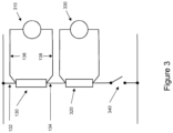
- FIG 3 schematically illustrates an electronic circuit driven by supply connections V pos and V neg , which can be used for driving the main heater track, simultaneously sensing a resistance of the main heater track, and calculating a temperature of the main heater track based on the sensed resistance.
- a control circuit may be included with the heater 100 or could be connected when the heater is in use.
- current flows through the heater track 130 via a positive drive connection 132 and a negative drive connection 134.
- the heater track is provided with 4-wire contacts to allow the voltage V sense across the heater track to be measured using positive voltage sense contact 136 and negative voltage sense contact 138 and a voltage measuring circuit 310.
- the current flowing through the heater track 130 is measured using a current sense resistor 320 with known resistance R isense and a voltage measuring circuit 330 for measuring the voltage V isense across the current sense resistor.
- Feedback-based driving of the main heater track may then be performed according to a sequence of temperature set points. Temperature control is implemented by determining setpoint values of R heater corresponding to desired temperature setpoints and controlling the heater drive to meet the heater resistance setpoint values. Alternatively, temperature control may be performed continuously across a temperature range based on the known temperature coefficient of resistance, TCR.
- a switch 340 which may be a transistor, is turned on to measure the heater resistance and is then turned off or left on for a predetermined time interval depending on whether R heater is above or below a currently required setpoint resistance.
- the switch 340 may driven with a pulse width modulated waveform with duty cycle selected to drive the heater with the required power. In both approaches the switch 340 is used to modulate the electrical drive to the main heater track to cycle the temperature of the reaction surface to carry out PCR amplification.
- the guard heater track may be operated with closed loop control with a temperature setpoint equal to or greater than the temperature setpoint of the main heater track or the guard heater track may be operated with the same controller or on/off timing as the main heater element but with a different drive voltage which can be adjusted to optimise the temperature uniformity at a specific temperature setpoint.
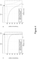
- FIGS. 4A and 4B the results of simulations of the temperature distributions on the reaction surface were obtained from the centre of a rectangular heater area to the edge in a longitudinal direction (A) and a transverse direction (B).
- temperature is shown on the vertical axis and position along the longitudinal/transverse direction from the centre is shown on the horizontal axis.
- Temperature distributions are shown without guard heater (solid lines) and with guard heater (dashed lines), showing more uniform temperature distribution when guard heaters are used.
- the locations of the main heater and guard heater are indicated on each of Figures 4A and 4B .
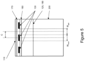
- FIG. 5 shows another schematic cross-section through the heater 100 and the heatsink 200.
- the main heater track 130 comprises a plurality of substantially parallel track sections having a width W track spaced apart by gaps of width W gap .
- the track sections need not be precisely parallel, so long as it is possible to define the gap width W gap .
- the heat output from the main heater track 130 is non-uniform due to the finite width of the tracks and gaps. This is exacerbated by the need to make a thickness H D of the thermal diffusion layer small in order to achieve rapid temperature changes.
- the thickness H D of the thermal diffusion layer is less than a minimum width of the track sections W track or less than a minimum gap width W gap .
- Narrower track and gap widths will increase temperature uniformity at the reaction surface, but this is limited by typical design rules, such as the requirements of PCB manufacturing techniques.
- Figure 5 also indicates a simulation region C for which the heater and heatsink were simulated.
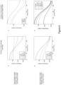
- Figures 6A, 6B, 6C and 6D show results of simulations of the temperature along the reaction surface within the simulation region C.
- the simulations assumed a heater with copper tracks where W track and W gap are constant at 75 ⁇ m, and further assumed that the heater track support layer 150 is made of FR4 and the thermal diffusion layer 160 is made of polypropylene.
- the effect of increasing a heat spreader layer thickness is shown for two cases where, in each Figure, temperature on the reaction surface is shown on the vertical axis and position along the reaction surface within simulation region C, starting from the centre of the heater track portion, is shown on the horizontal axis.
- Figure 6A shows the results of simulations where a reaction surface heat spreader layer 170 made of aluminium is located within the thermal diffusion layer, between the heater tracks and the reaction surface 110, at a distance of 10 ⁇ m from the heater tracks, and reaction surface heat spreader layer 180 is omitted (configuration A).
- Figure 6B shows the results of simulations where a reaction surface heat spreader layer 180 made of aluminium is located within the heater track support layer, between the heater tracks and the back surface 120 of the heater, at a distance of 5 ⁇ m from the heater tracks, and reaction surface heat spreader layer 170 is omitted (configuration B).
- the heat spreader layer increases temperature uniformity, with thicker heat spreader layers being more effective, and configuration A is more effective than configuration B.
- Figures 6C and 6D show simulation results in which the location of a reaction surface heat spreader layer 170 is varied.
- the reaction surface heat spreader is located in the thermal diffusion layer, and the distances shown in the legend of the graph in Figure 6C show the separation of the upper surface of the heater tracks and the heat spreader layer.
- the heat spreader is located in the heater support layer and the distances shown in the legend of the graph in Figure 6D show the separation of the lower surface of the heater tracks and the heat spreader layer.
- the heat spreader is made of aluminium and has thickness 100nm. The reaction surface heat spreader position has little impact on temperature uniformity when the heat spreader is located within the thermal diffusion layer ( Figure 6C ).
- reaction surface heat spreader when the reaction surface heat spreader is located in the heater support layer, the reaction surface heat spreader is preferably located within 15 ⁇ m of the heater in order to provide a substantial improvement in temperature uniformity ( Figure 6D ). This distance scales with the track and gap width and corresponds to 20% of the minimum track and gap width as evaluated in the central region.
- the heater 100 includes a back surface heat spreader 190. While this feature is not required in all embodiments of the invention, the back surface heat spreader 190 has the advantage of further improving temperature uniformity at the reaction surface 110 as demonstrated using simulations.
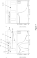
- Figures 7A and 7B show simulation results comparing heaters without ( Figure 7A ) and with ( Figure 7B ) a back surface heat spreader 190.
- the upper plot shows temperature contours from 40°C to 60°C on a simulated heater.
- the simulated heater includes heater tracks shown as a dashed line, where shorter dashes indicate the main heater track 130 and longer dashes indicate the guard heater track 140.
- a reaction cell 710 is surrounded by the thermal diffusion layer 160 having the reaction surface 110, such that a temperature of the contents of the reaction cell can be controlled according to the temperature of the reaction surface.
- the lower plot shows the temperature profile along the reaction surface (solid line, "A” in legend), in a plane cutting through the heater tracks ("B” in legend) and on the back surface of the heater ("C” in legend).
- the simulation of Figure 7B assumes that the back surface heat spreader is constructed from a 12 ⁇ m thick layer of copper.
- a heat sink 200 with non-uniform thermal contact is represented by a set of three aluminium pillars, width 0.5mm and height 1.0mm.
- Figure 8 shows simulation of the transient response of a heater as described above with a back surface heat spreader, thermocycling with 4s cycle time using temperature setpoints of 58°C, 73°C and 98°C.
- the temperature of the main heater track is shown in trace A (dashed line) and the temperature at the centre of the reaction surface is shown in trace B (solid line).
- a heater according to the invention may be used for providing heat to a reaction.
- the reaction surface of the heater is located in contact with a reaction cell having a reaction volume containing a sample.
- the heater element is switched on, and heat generated by the heater element flows through the reaction surface into the reaction volume. If rapid cooling is required, the heater can contact a heat sink on its back surface so that when the heater element is switched off, heat flows from the reaction surface, through the heater and into the heat sink.
- Table 1 below shows an example choice of materials for a heater according to the invention, in which the thermal diffusion time of the thermal diffusion layer is less than the reaction time for PCR, which we take as approximately 1s for amplification of a 100 base pair DNA sequence.
- the thermal resistance of the heater track support layer R T can be optimised to minimise the thermal cycling time for a given temperature profile and heatsink temperature T Sink and heater power p Heat .
- Table 2 shows example values for heater power, optimal thermal resistance and thermal cycle time. These are shown for the case of a reaction surface with area 50mm 2 and with heat capacity 0.04 J/K, cycling between 60°C and 95°C with a heat sink temperature of 30°C.
- Figure 9 shows an alternative schematic layout of resistive heating tracks in a heater 100 according to the invention.
- two main heater tracks 130 are arranged next to each other in order to heat individual respective areas of a reaction surface 110.
- the main heater tracks are both surrounded and separated by a guard heater track 140.
- FIG. 9 illustrates how a heater according to the invention may be provided with a main heater track for each of a plurality of individually temperature-controlled areas of a reaction surface.
- the guard heater track 140 inhibits lateral heat flow and thereby increases the accuracy with which each of the individual areas of the reaction surface may be temperature-controlled.
- the guard heater track 140 has three connections 142, 144 and 146 such that the current and heat output per unit area may be different between and around the two main heater tracks 130.
- each main heater track 130 may be provided with a separate guard heater track 140 with two connections.
- the heater is provided in an assembly with a heat sink.
- the invention is also applicable in cases where uniform heating is required, but a heat sink is not required.
- the heat sink may be omitted for applications where a cooling time is less important.
- the heater is provided with a guard heater track 140.
- the main heater track 130 may be designed to have higher heat output near its edges and to extend beyond the reaction volume. This higher heat output effect may be achieved by increasing the density of the heater track by reducing the gap width between two or more heater track portions near the edge of the main heater track as compared to heater track portions at the centre of the main heater track. Additionally or alternatively, this effect may be achieved by increasing the resistance of the main heater track by reducing the width or height of one or more heater track portions near the edge of the main heater track as compared to heater track portions at the centre of the main heater track.
- the higher heat output of the heater element near its edges can compensate for lateral heat flow and provide more uniform temperature conditions across the reaction volume. Furthermore, where a heater has a reaction surface that extends significantly beyond the required reaction volume, it is possible to omit both of the guard heater track and the modifications near the edge of the main heater track.
- Table 1 Example heater materials, thermal properties and layer thicknesses.
- Heat sink temperature T Sink °C 30 Lower cycling temperature, T LOW °C 60 Higher cycling temperature, T HIGH °C 95 Reaction surface area, A cell m 2 5E-05 Reactor heat capacity, h J/K 0.04 Heater power, p heat W 47.50 15.83 4.75 1.58 0.48
- Optimal thermal resistance from heater to heatsink R T,Opt K/W 2 6 20 60 200 Thermal resistance ⁇ area, R T,Opt ⁇ A cell K.m 2 /W 1E-04 3E-04 1E-03 3E-03 1E-02 Thermal time constant, h ⁇ R T,Opt s 0.13 0.38 0.76 1.52 5.07 Cooling time, t cool s 0.10 0.29 0.59 1.18 3.92 Heating time, t heat s 0.10 0.29 0.59 1.18 3.92 Minimum cycle time, t cycle s 0.20 0.59 1.18 2.35 7.83 Energy consumed per cycle, E cycle J 2.94 2.94 2.94 2.94 2.94 2.94 2.94
Landscapes
- Chemical & Material Sciences (AREA)
- Health & Medical Sciences (AREA)
- Clinical Laboratory Science (AREA)
- Biochemistry (AREA)
- General Health & Medical Sciences (AREA)
- Molecular Biology (AREA)
- Life Sciences & Earth Sciences (AREA)
- Chemical Kinetics & Catalysis (AREA)
- Apparatus Associated With Microorganisms And Enzymes (AREA)
- Measuring Or Testing Involving Enzymes Or Micro-Organisms (AREA)
- Control Of Temperature (AREA)
- Resistance Heating (AREA)
- Physical Or Chemical Processes And Apparatus (AREA)
Claims (14)
- Heizer (100) für Thermocycling zur Durchführung von PCR-Amplifikation, wobei der Heizer umfasst:eine Thermodiffusionsschicht (160) mit einer Reaktionsoberfläche (110) zum Übertragen von Wärme an eine Reaktionszelle;eine Heizerbahnträgerschicht (150) mit einer rückwärtigen Oberfläche (120) zur Kühlung;eine elektrisch leitfähige Hauptheizerbahn (130), die zwischen der Heizerbahnträgerschicht und der Thermodiffusionsschicht getragen wird; undvierpolige elektrische Kontakte (132, 134, 136, 138) zu der Hauptheizerbahn, die eingerichtet sind, um elektrische Verbindung zum Antreiben der Hauptheizerbahn und zum gleichzeitigen Abfühlen eines Widerstands der Hauptheizerbahn bereitzustellen,wobei die lateralen Abmessungen der Reaktionsoberfläche größer als eine Dicke H des Heizers sind, so dass der Flächeninhalt der Reaktionsoberfläche A > H 2 ist,wobei der Heizer des Weiteren eine Wärmeverteilungsschicht (170, 180) der Reaktionsoberfläche umfasst, die sich in Kontakt mit oder innerhalb von einer von der Thermodiffusionsschicht (160) oder der Heizerbahnträgerschicht (150) befindet,wobei eine Wärmeverteilungsschicht der rückwärtigen Oberfläche sich auf der rückwärtigen Oberfläche befindet.
- Heizer nach Anspruch 1, wobei die Hauptheizerbahn (130) eine zentrale Region (131) umfasst, umfassend eine Vielzahl von im Wesentlichen parallelen Bahnsegmenten mit Breiten WBahn und getrennt durch Spalten mit der Breite WSpalt, wobei die Dicke HD der Thermodiffusionsschicht (160) kleiner als eine minimale Breite der Bahnsegmente WBahn oder kleiner als eine minimale Spaltbreite WSpalt ist, wobei WBahn oder WSpalt in der zentralen Region (131) der Hauptheizerbahn bewertet werden.
- Heizer nach Anspruch 2, wobei die Spaltbreite WSpalt und/oder die Breite der Bahnsegmente WBahn für ein Bahnsegment (133) nahe dem Rand der Hauptheizerbahn niedriger als für ein Bahnsegment (131) in der zentralen Region der Hauptheizerbahn ist/sind.
- Heizer nach einem der vorhergehenden Ansprüche, des Weiteren umfassend:eine Schutzheizerbahn (140) zwischen der Heizerbahnträgerschicht (150) und der Thermodiffusionsschicht (160), wobei die Schutzheizerbahn die Hauptheizerbahn (130) im Wesentlichen umgibt; undzwei weitere elektrische Kontakte (142, 144) zu der Schutzheizerbahn unabhängig von den vierpoligen elektrischen Kontakten zu der Hauptheizerbahn.
- Heizer nach einem der vorhergehenden Ansprüche, wobei die Heizerbahnträgerschicht (150) ein Produkt aus Wärmewiderstand × Flächeninhalt im Bereich von 1×10⁻⁴ bis 1×10⁻² K.m2/W und bevorzugter im Bereich von 3×10⁻⁴ bis 3×10⁻³ K.m2/W hat.
- Heizer nach Anspruch 1, wobei die Wärmeverteilungsschicht (170, 180) der Reaktionsoberfläche wärmeleitfähiger ist, eine größere laterale Wärmeleitfähigkeit hat und eine niedrigere Wärmekapazität hat als die eine von der Thermodiffusionsschicht (160) oder der Heizerbahnträgerschicht (150).
- Heizer nach Anspruch 2 oder Anspruch 3, wobei die Wärmeverteilungsschicht (170, 180) der Reaktionsoberfläche sich innerhalb der Heizerbahnträgerschicht (150) in einem Abstand Ls zu der Hauptheizerbahn (130) befindet, wobei Ls kleiner als 20 % des Minimums der Heizerbahnbreite WBahn und der Heizerspaltbreite WSpalt ist, bewertet in der zentralen Region (131).
- Heizer nach einem der vorhergehenden Ansprüche, wobei eine Wärmeverteilungsschicht der rückwärtigen Oberfläche sich auf der rückwärtigen Oberfläche befindet.
- Heizer nach einem der vorhergehenden Ansprüche, des Weiteren umfassend eine Wärmesenke (200) in Kontakt mit der rückwärtigen Oberfläche.
- Einweg-Verbrauchsartikel, umfassend einen Heizer (100) gemäß einem der vorhergehenden Ansprüche und eine Reaktionszelle, die in Kontakt mit der Reaktionsoberfläche angeordnet ist.
- Verfahren zum Betreiben eines Heizers (100) oder eines Reaktors mit variabler Temperatur gemäß einem der vorhergehenden Ansprüche, umfassend Antreiben der Hauptheizerbahn (130), gleichzeitiges Abfühlen eines Widerstands der Hauptheizerbahn, und Berechnen einer Temperatur der Hauptheizerbahn basierend auf dem abgefühlten Widerstand.
- Verfahren nach Anspruch 11, umfassend Durchführen von rückmeldebasiertem Antreiben der Hauptheizerbahn (130) gemäß einer Sequenz von Temperatursollwerten für die Hauptheizerbahn, um die Temperatur der Reaktionsoberfläche zyklisch zu führen, um PCR-Amplifikation durchzuführen.
- Verfahren nach Anspruch 11 oder Anspruch 12, wobei der Heizer (100) ein Heizer gemäß Anspruch 4 ist und das Verfahren des Weiteren Antreiben der Schutzheizerbahn (140) umfasst, um eine höhere Wärmeabgabe pro Flächeneinheit als die Hauptheizerbahn (130) bereitzustellen.
- Heizer (100) oder Einweg-Verbrauchsartikel nach einem der Ansprüche 1 bis 10, des Weiteren umfassend eine Steuerschaltung, die ausgelegt ist, um ein Verfahren gemäß einem der Ansprüche 11 bis 13 durchzuführen.
Priority Applications (8)
| Application Number | Priority Date | Filing Date | Title |
|---|---|---|---|
| EP19188688.6A EP3769843B1 (de) | 2019-07-26 | 2019-07-26 | Heizer |
| EP20742787.3A EP4003600A1 (de) | 2019-07-26 | 2020-07-24 | Heizer |
| JP2022505479A JP7812783B2 (ja) | 2019-07-26 | 2020-07-24 | ヒータ |
| US17/630,468 US20220250080A1 (en) | 2019-07-26 | 2020-07-24 | Heater |
| CN202080063456.6A CN114375323A (zh) | 2019-07-26 | 2020-07-24 | 加热器 |
| CA3148777A CA3148777A1 (en) | 2019-07-26 | 2020-07-24 | Heater |
| AU2020321480A AU2020321480B2 (en) | 2019-07-26 | 2020-07-24 | Heater |
| PCT/EP2020/071059 WO2021018807A1 (en) | 2019-07-26 | 2020-07-24 | Heater |
Applications Claiming Priority (1)
| Application Number | Priority Date | Filing Date | Title |
|---|---|---|---|
| EP19188688.6A EP3769843B1 (de) | 2019-07-26 | 2019-07-26 | Heizer |
Publications (3)
| Publication Number | Publication Date |
|---|---|
| EP3769843A1 EP3769843A1 (de) | 2021-01-27 |
| EP3769843C0 EP3769843C0 (de) | 2024-10-30 |
| EP3769843B1 true EP3769843B1 (de) | 2024-10-30 |
Family
ID=67439132
Family Applications (2)
| Application Number | Title | Priority Date | Filing Date |
|---|---|---|---|
| EP19188688.6A Active EP3769843B1 (de) | 2019-07-26 | 2019-07-26 | Heizer |
| EP20742787.3A Pending EP4003600A1 (de) | 2019-07-26 | 2020-07-24 | Heizer |
Family Applications After (1)
| Application Number | Title | Priority Date | Filing Date |
|---|---|---|---|
| EP20742787.3A Pending EP4003600A1 (de) | 2019-07-26 | 2020-07-24 | Heizer |
Country Status (7)
| Country | Link |
|---|---|
| US (1) | US20220250080A1 (de) |
| EP (2) | EP3769843B1 (de) |
| JP (1) | JP7812783B2 (de) |
| CN (1) | CN114375323A (de) |
| AU (1) | AU2020321480B2 (de) |
| CA (1) | CA3148777A1 (de) |
| WO (1) | WO2021018807A1 (de) |
Families Citing this family (1)
| Publication number | Priority date | Publication date | Assignee | Title |
|---|---|---|---|---|
| GB201812192D0 (en) | 2018-07-26 | 2018-09-12 | Ttp Plc | Variable temperature reactor, heater and control circuit for the same |
Family Cites Families (10)
| Publication number | Priority date | Publication date | Assignee | Title |
|---|---|---|---|---|
| US6477479B1 (en) * | 1998-12-11 | 2002-11-05 | Symyx Technologies | Sensor array for rapid materials characterization |
| US6337435B1 (en) * | 1999-07-30 | 2002-01-08 | Bio-Rad Laboratories, Inc. | Temperature control for multi-vessel reaction apparatus |
| JP2002141163A (ja) | 2000-10-31 | 2002-05-17 | Kyocera Corp | セラミックヒーター及びこれを用いた光合分波器 |
| EP1878501A1 (de) * | 2006-07-14 | 2008-01-16 | Roche Diagnostics GmbH | Vorrichtung zur Heizung und Kühlung |
| US8306773B2 (en) * | 2007-08-29 | 2012-11-06 | Canon U.S. Life Sciences, Inc. | Microfluidic devices with integrated resistive heater electrodes including systems and methods for controlling and measuring the temperatures of such heater electrodes |
| EP2689005A4 (de) * | 2011-03-23 | 2014-09-03 | California Inst Of Techn | System zur durchführung einer nukleinsäureamplifikation für eine polymerasekettenreaktion |
| EP2710859B1 (de) * | 2011-05-17 | 2019-09-04 | Canon U.S. Life Sciences, Inc. | Systeme und verfahren mit externen erwärmungssystemen in mikrofluidischen vorrichtungen |
| EP3068536A4 (de) * | 2013-11-13 | 2017-07-26 | Canon U.S. Life Sciences, Inc. | Thermische steuerungssysteme und -verfahren mit thermisch geschützten multiplex-sensoren |
| JP6856619B2 (ja) * | 2015-07-23 | 2021-04-07 | セフェィド | 熱制御装置、使用方法、及び熱管理システム |
| US11123739B2 (en) * | 2016-04-15 | 2021-09-21 | Cbf Systems Inc. | Thermal cycling methods and apparatuses for carrying out efficient polymerase chain reaction (PCR) processes to amplify deoxyribonucleic acid (DNA) |
-
2019
- 2019-07-26 EP EP19188688.6A patent/EP3769843B1/de active Active
-
2020
- 2020-07-24 US US17/630,468 patent/US20220250080A1/en active Pending
- 2020-07-24 CN CN202080063456.6A patent/CN114375323A/zh active Pending
- 2020-07-24 AU AU2020321480A patent/AU2020321480B2/en active Active
- 2020-07-24 JP JP2022505479A patent/JP7812783B2/ja active Active
- 2020-07-24 CA CA3148777A patent/CA3148777A1/en active Pending
- 2020-07-24 WO PCT/EP2020/071059 patent/WO2021018807A1/en not_active Ceased
- 2020-07-24 EP EP20742787.3A patent/EP4003600A1/de active Pending
Also Published As
| Publication number | Publication date |
|---|---|
| EP3769843A1 (de) | 2021-01-27 |
| JP7812783B2 (ja) | 2026-02-10 |
| EP3769843C0 (de) | 2024-10-30 |
| CN114375323A (zh) | 2022-04-19 |
| AU2020321480B2 (en) | 2025-11-20 |
| AU2020321480A1 (en) | 2022-02-17 |
| EP4003600A1 (de) | 2022-06-01 |
| CA3148777A1 (en) | 2021-02-04 |
| JP2022543212A (ja) | 2022-10-11 |
| WO2021018807A1 (en) | 2021-02-04 |
| US20220250080A1 (en) | 2022-08-11 |
Similar Documents
| Publication | Publication Date | Title |
|---|---|---|
| EP0545736B1 (de) | Verfahren und Gerät zur Temperaturregelung von Vielfachproben | |
| US9538583B2 (en) | Substrate support with switchable multizone heater | |
| US10835900B2 (en) | Microfluidic device with multiple temperature zones | |
| TWI751180B (zh) | 靜電夾頭加熱器 | |
| US11845080B2 (en) | Temperature control system for microfluidic device | |
| US12551897B2 (en) | Variable temperature reactor, heater, and control circuit for the same | |
| KR20120020528A (ko) | 중합효소 연쇄반응 장치 | |
| EP3769843B1 (de) | Heizer | |
| WO1993009486A1 (en) | Reaction temperature control device | |
| EP1425101B1 (de) | Heizung zur zonalen temperierung von probenträgern | |
| US12356508B2 (en) | Heater temperature control method, heater, and placement stand | |
| US9499896B2 (en) | Thermocycling system, composition, and microfabrication method | |
| US20140130518A1 (en) | Temperature control device and temperature element | |
| CN112189129A (zh) | 诊断测试传感器内的整体温度控制 | |
| CN116273225A (zh) | 一种集成加热功能的pcb数字微流控芯片 | |
| JP2006064365A (ja) | 温度調節装置 | |
| US5196865A (en) | Temperature sensing of heater points in thermal print heads by resistive layer beneath the heating points | |
| US20250069913A1 (en) | Heater system for gas processing components | |
| US20240063170A1 (en) | Mounting head | |
| JP2000010639A (ja) | ゾーン分割ヒータの温度制御装置 | |
| HK1250683A1 (en) | Microfluidic device with multiple temperature zones | |
| HK1114809A (en) | Temperature sensor element for monitoring heating and cooling | |
| JP2016019503A (ja) | デバイスの温度制御方法、温度制御装置、分析装置、および分析システム |
Legal Events
| Date | Code | Title | Description |
|---|---|---|---|
| PUAI | Public reference made under article 153(3) epc to a published international application that has entered the european phase |
Free format text: ORIGINAL CODE: 0009012 |
|
| STAA | Information on the status of an ep patent application or granted ep patent |
Free format text: STATUS: THE APPLICATION HAS BEEN PUBLISHED |
|
| AK | Designated contracting states |
Kind code of ref document: A1 Designated state(s): AL AT BE BG CH CY CZ DE DK EE ES FI FR GB GR HR HU IE IS IT LI LT LU LV MC MK MT NL NO PL PT RO RS SE SI SK SM TR |
|
| AX | Request for extension of the european patent |
Extension state: BA ME |
|
| STAA | Information on the status of an ep patent application or granted ep patent |
Free format text: STATUS: REQUEST FOR EXAMINATION WAS MADE |
|
| 17P | Request for examination filed |
Effective date: 20210723 |
|
| RBV | Designated contracting states (corrected) |
Designated state(s): AL AT BE BG CH CY CZ DE DK EE ES FI FR GB GR HR HU IE IS IT LI LT LU LV MC MK MT NL NO PL PT RO RS SE SI SK SM TR |
|
| GRAP | Despatch of communication of intention to grant a patent |
Free format text: ORIGINAL CODE: EPIDOSNIGR1 |
|
| STAA | Information on the status of an ep patent application or granted ep patent |
Free format text: STATUS: GRANT OF PATENT IS INTENDED |
|
| INTG | Intention to grant announced |
Effective date: 20240524 |
|
| GRAS | Grant fee paid |
Free format text: ORIGINAL CODE: EPIDOSNIGR3 |
|
| GRAA | (expected) grant |
Free format text: ORIGINAL CODE: 0009210 |
|
| STAA | Information on the status of an ep patent application or granted ep patent |
Free format text: STATUS: THE PATENT HAS BEEN GRANTED |
|
| AK | Designated contracting states |
Kind code of ref document: B1 Designated state(s): AL AT BE BG CH CY CZ DE DK EE ES FI FR GB GR HR HU IE IS IT LI LT LU LV MC MK MT NL NO PL PT RO RS SE SI SK SM TR |
|
| REG | Reference to a national code |
Ref country code: GB Ref legal event code: FG4D |
|
| REG | Reference to a national code |
Ref country code: CH Ref legal event code: EP |
|
| REG | Reference to a national code |
Ref country code: IE Ref legal event code: FG4D |
|
| REG | Reference to a national code |
Ref country code: DE Ref legal event code: R096 Ref document number: 602019061037 Country of ref document: DE |
|
| U01 | Request for unitary effect filed |
Effective date: 20241120 |
|
| U07 | Unitary effect registered |
Designated state(s): AT BE BG DE DK EE FI FR IT LT LU LV MT NL PT RO SE SI Effective date: 20241127 |
|
| PG25 | Lapsed in a contracting state [announced via postgrant information from national office to epo] |
Ref country code: HR Free format text: LAPSE BECAUSE OF FAILURE TO SUBMIT A TRANSLATION OF THE DESCRIPTION OR TO PAY THE FEE WITHIN THE PRESCRIBED TIME-LIMIT Effective date: 20241030 Ref country code: IS Free format text: LAPSE BECAUSE OF FAILURE TO SUBMIT A TRANSLATION OF THE DESCRIPTION OR TO PAY THE FEE WITHIN THE PRESCRIBED TIME-LIMIT Effective date: 20250228 |
|
| PG25 | Lapsed in a contracting state [announced via postgrant information from national office to epo] |
Ref country code: ES Free format text: LAPSE BECAUSE OF FAILURE TO SUBMIT A TRANSLATION OF THE DESCRIPTION OR TO PAY THE FEE WITHIN THE PRESCRIBED TIME-LIMIT Effective date: 20241030 |
|
| PG25 | Lapsed in a contracting state [announced via postgrant information from national office to epo] |
Ref country code: NO Free format text: LAPSE BECAUSE OF FAILURE TO SUBMIT A TRANSLATION OF THE DESCRIPTION OR TO PAY THE FEE WITHIN THE PRESCRIBED TIME-LIMIT Effective date: 20250130 |
|
| PG25 | Lapsed in a contracting state [announced via postgrant information from national office to epo] |
Ref country code: GR Free format text: LAPSE BECAUSE OF FAILURE TO SUBMIT A TRANSLATION OF THE DESCRIPTION OR TO PAY THE FEE WITHIN THE PRESCRIBED TIME-LIMIT Effective date: 20250131 |
|
| PG25 | Lapsed in a contracting state [announced via postgrant information from national office to epo] |
Ref country code: PL Free format text: LAPSE BECAUSE OF FAILURE TO SUBMIT A TRANSLATION OF THE DESCRIPTION OR TO PAY THE FEE WITHIN THE PRESCRIBED TIME-LIMIT Effective date: 20241030 |
|
| PG25 | Lapsed in a contracting state [announced via postgrant information from national office to epo] |
Ref country code: RS Free format text: LAPSE BECAUSE OF FAILURE TO SUBMIT A TRANSLATION OF THE DESCRIPTION OR TO PAY THE FEE WITHIN THE PRESCRIBED TIME-LIMIT Effective date: 20250130 |
|
| PG25 | Lapsed in a contracting state [announced via postgrant information from national office to epo] |
Ref country code: SM Free format text: LAPSE BECAUSE OF FAILURE TO SUBMIT A TRANSLATION OF THE DESCRIPTION OR TO PAY THE FEE WITHIN THE PRESCRIBED TIME-LIMIT Effective date: 20241030 |
|
| PGFP | Annual fee paid to national office [announced via postgrant information from national office to epo] |
Ref country code: GB Payment date: 20250605 Year of fee payment: 7 |
|
| U20 | Renewal fee for the european patent with unitary effect paid |
Year of fee payment: 7 Effective date: 20250606 |
|
| PG25 | Lapsed in a contracting state [announced via postgrant information from national office to epo] |
Ref country code: SK Free format text: LAPSE BECAUSE OF FAILURE TO SUBMIT A TRANSLATION OF THE DESCRIPTION OR TO PAY THE FEE WITHIN THE PRESCRIBED TIME-LIMIT Effective date: 20241030 |
|
| PG25 | Lapsed in a contracting state [announced via postgrant information from national office to epo] |
Ref country code: CZ Free format text: LAPSE BECAUSE OF FAILURE TO SUBMIT A TRANSLATION OF THE DESCRIPTION OR TO PAY THE FEE WITHIN THE PRESCRIBED TIME-LIMIT Effective date: 20241030 |
|
| PLBE | No opposition filed within time limit |
Free format text: ORIGINAL CODE: 0009261 |
|
| STAA | Information on the status of an ep patent application or granted ep patent |
Free format text: STATUS: NO OPPOSITION FILED WITHIN TIME LIMIT |
|
| 26N | No opposition filed |
Effective date: 20250731 |
|
| PGFP | Annual fee paid to national office [announced via postgrant information from national office to epo] |
Ref country code: CH Payment date: 20250918 Year of fee payment: 7 |