EP3769833A1 - Filterelement mit funktionsraum und filteranordnung mit solchem filterelement und verfahren zur steuerung eines filtersystems - Google Patents
Filterelement mit funktionsraum und filteranordnung mit solchem filterelement und verfahren zur steuerung eines filtersystems Download PDFInfo
- Publication number
- EP3769833A1 EP3769833A1 EP19188126.7A EP19188126A EP3769833A1 EP 3769833 A1 EP3769833 A1 EP 3769833A1 EP 19188126 A EP19188126 A EP 19188126A EP 3769833 A1 EP3769833 A1 EP 3769833A1
- Authority
- EP
- European Patent Office
- Prior art keywords
- filter element
- filter
- bellows
- sensor
- recess
- Prior art date
- Legal status (The legal status is an assumption and is not a legal conclusion. Google has not performed a legal analysis and makes no representation as to the accuracy of the status listed.)
- Granted
Links
- 238000000034 method Methods 0.000 title claims description 3
- 239000003205 fragrance Substances 0.000 claims abstract description 27
- 239000000126 substance Substances 0.000 claims description 10
- 230000005540 biological transmission Effects 0.000 claims description 7
- 238000005259 measurement Methods 0.000 claims description 5
- 238000001914 filtration Methods 0.000 claims description 4
- 230000001590 oxidative effect Effects 0.000 claims description 4
- 239000007789 gas Substances 0.000 description 24
- 238000011161 development Methods 0.000 description 8
- 230000018109 developmental process Effects 0.000 description 8
- 230000000694 effects Effects 0.000 description 6
- 238000004140 cleaning Methods 0.000 description 5
- 239000007800 oxidant agent Substances 0.000 description 2
- 238000007789 sealing Methods 0.000 description 2
- 239000005708 Sodium hypochlorite Substances 0.000 description 1
- 241000700605 Viruses Species 0.000 description 1
- 238000004891 communication Methods 0.000 description 1
- 238000010276 construction Methods 0.000 description 1
- 238000011109 contamination Methods 0.000 description 1
- 230000002950 deficient Effects 0.000 description 1
- 230000010354 integration Effects 0.000 description 1
- 244000005700 microbiome Species 0.000 description 1
- 239000002245 particle Substances 0.000 description 1
- 230000002265 prevention Effects 0.000 description 1
- 150000004760 silicates Chemical class 0.000 description 1
- SUKJFIGYRHOWBL-UHFFFAOYSA-N sodium hypochlorite Chemical compound [Na+].Cl[O-] SUKJFIGYRHOWBL-UHFFFAOYSA-N 0.000 description 1
Images
Classifications
-
- B—PERFORMING OPERATIONS; TRANSPORTING
- B01—PHYSICAL OR CHEMICAL PROCESSES OR APPARATUS IN GENERAL
- B01D—SEPARATION
- B01D46/00—Filters or filtering processes specially modified for separating dispersed particles from gases or vapours
- B01D46/10—Particle separators, e.g. dust precipitators, using filter plates, sheets or pads having plane surfaces
-
- B—PERFORMING OPERATIONS; TRANSPORTING
- B01—PHYSICAL OR CHEMICAL PROCESSES OR APPARATUS IN GENERAL
- B01D—SEPARATION
- B01D46/00—Filters or filtering processes specially modified for separating dispersed particles from gases or vapours
- B01D46/42—Auxiliary equipment or operation thereof
-
- B—PERFORMING OPERATIONS; TRANSPORTING
- B01—PHYSICAL OR CHEMICAL PROCESSES OR APPARATUS IN GENERAL
- B01D—SEPARATION
- B01D46/00—Filters or filtering processes specially modified for separating dispersed particles from gases or vapours
- B01D46/52—Particle separators, e.g. dust precipitators, using filters embodying folded corrugated or wound sheet material
- B01D46/521—Particle separators, e.g. dust precipitators, using filters embodying folded corrugated or wound sheet material using folded, pleated material
-
- A—HUMAN NECESSITIES
- A61—MEDICAL OR VETERINARY SCIENCE; HYGIENE
- A61L—METHODS OR APPARATUS FOR STERILISING MATERIALS OR OBJECTS IN GENERAL; DISINFECTION, STERILISATION OR DEODORISATION OF AIR; CHEMICAL ASPECTS OF BANDAGES, DRESSINGS, ABSORBENT PADS OR SURGICAL ARTICLES; MATERIALS FOR BANDAGES, DRESSINGS, ABSORBENT PADS OR SURGICAL ARTICLES
- A61L9/00—Disinfection, sterilisation or deodorisation of air
- A61L9/015—Disinfection, sterilisation or deodorisation of air using gaseous or vaporous substances, e.g. ozone
- A61L9/04—Disinfection, sterilisation or deodorisation of air using gaseous or vaporous substances, e.g. ozone using substances evaporated in the air without heating
- A61L9/12—Apparatus, e.g. holders, therefor
-
- B—PERFORMING OPERATIONS; TRANSPORTING
- B01—PHYSICAL OR CHEMICAL PROCESSES OR APPARATUS IN GENERAL
- B01D—SEPARATION
- B01D46/00—Filters or filtering processes specially modified for separating dispersed particles from gases or vapours
- B01D46/0027—Filters or filtering processes specially modified for separating dispersed particles from gases or vapours with additional separating or treating functions
- B01D46/0038—Filters or filtering processes specially modified for separating dispersed particles from gases or vapours with additional separating or treating functions with means for influencing the odor, e.g. deodorizing substances
-
- B—PERFORMING OPERATIONS; TRANSPORTING
- B01—PHYSICAL OR CHEMICAL PROCESSES OR APPARATUS IN GENERAL
- B01D—SEPARATION
- B01D46/00—Filters or filtering processes specially modified for separating dispersed particles from gases or vapours
- B01D46/0084—Filters or filtering processes specially modified for separating dispersed particles from gases or vapours provided with safety means
- B01D46/0086—Filter condition indicators
-
- B—PERFORMING OPERATIONS; TRANSPORTING
- B01—PHYSICAL OR CHEMICAL PROCESSES OR APPARATUS IN GENERAL
- B01D—SEPARATION
- B01D46/00—Filters or filtering processes specially modified for separating dispersed particles from gases or vapours
- B01D46/42—Auxiliary equipment or operation thereof
- B01D46/429—Means for wireless communication
-
- B—PERFORMING OPERATIONS; TRANSPORTING
- B01—PHYSICAL OR CHEMICAL PROCESSES OR APPARATUS IN GENERAL
- B01D—SEPARATION
- B01D46/00—Filters or filtering processes specially modified for separating dispersed particles from gases or vapours
- B01D46/42—Auxiliary equipment or operation thereof
- B01D46/44—Auxiliary equipment or operation thereof controlling filtration
-
- B—PERFORMING OPERATIONS; TRANSPORTING
- B60—VEHICLES IN GENERAL
- B60H—ARRANGEMENTS OF HEATING, COOLING, VENTILATING OR OTHER AIR-TREATING DEVICES SPECIALLY ADAPTED FOR PASSENGER OR GOODS SPACES OF VEHICLES
- B60H3/00—Other air-treating devices
- B60H3/0007—Adding substances other than water to the air, e.g. perfume, oxygen
- B60H3/0014—Adding substances other than water to the air, e.g. perfume, oxygen characterised by the location of the substance adding device
-
- B—PERFORMING OPERATIONS; TRANSPORTING
- B60—VEHICLES IN GENERAL
- B60H—ARRANGEMENTS OF HEATING, COOLING, VENTILATING OR OTHER AIR-TREATING DEVICES SPECIALLY ADAPTED FOR PASSENGER OR GOODS SPACES OF VEHICLES
- B60H3/00—Other air-treating devices
- B60H3/06—Filtering
- B60H3/0658—Filter elements specially adapted for their arrangement in vehicles
-
- B—PERFORMING OPERATIONS; TRANSPORTING
- B01—PHYSICAL OR CHEMICAL PROCESSES OR APPARATUS IN GENERAL
- B01D—SEPARATION
- B01D46/00—Filters or filtering processes specially modified for separating dispersed particles from gases or vapours
- B01D46/52—Particle separators, e.g. dust precipitators, using filters embodying folded corrugated or wound sheet material
-
- B—PERFORMING OPERATIONS; TRANSPORTING
- B60—VEHICLES IN GENERAL
- B60H—ARRANGEMENTS OF HEATING, COOLING, VENTILATING OR OTHER AIR-TREATING DEVICES SPECIALLY ADAPTED FOR PASSENGER OR GOODS SPACES OF VEHICLES
- B60H3/00—Other air-treating devices
- B60H3/06—Filtering
- B60H2003/0683—Filtering the quality of the filter or the air being checked
Definitions
- the invention relates to a filter element with a functional space according to the preamble of claim 1.
- a filter element with an integrated container is known.
- the container can serve to hold a scenting element.
- fragrance elements an air flow in the filter element can be mixed with a certain fragrance.
- US 2007/0261376 A1 and the EP 2 868 987 A1 filter elements emerge with fragrance elements.
- the WO 2016/016085 A1 and the US 2003/0052791 A1 filter elements are known that have sensors.
- the sensors are attached directly to the filter medium.
- the object of the present invention is to create a filter element which has a functional space which in a simple manner enables at least one sensor element and / or at least one fragrance element to be provided and the fragrance elements to be exchanged easily.
- a further object is to create a filter arrangement which enables a filter element to be exchanged easily, in particular if the filter element comprises a reusable sensor element.
- the filter element according to the invention has a bellows made of a pleated filter medium with a large number of folded edges and folded surfaces and has edge strips to delimit the filter medium, so that in each case one edge strip forms a wall of the filter element.
- the filter element has a functional space which is firmly connected to the filter element, adjoins the bellows and is arranged within the edge strips.
- An interface is arranged between the bellows and the functional space and separates the bellows from the functional space.
- the interface is advantageously provided with at least one recess, for example a recess or a hole for receiving sensor elements and / or fragrance elements.
- the sensor elements can be used to measure particles, gases, fragrances, etc. in an air flow through the filter element.
- the sensor elements and / or scenting elements are not only receivable in the filter element but actually present and are part of the filter element.
- the recesses are designed such that a sensor head of the sensor element or the scenting element can be positioned in the area of the bellows. So that there is sufficient space for the sensor elements and / or scenting elements, the pleat spacing and / or the pleat height of the bellows can possibly be changed locally so that more space is created for sensor elements or scenting elements. Any existing fragrancing elements are preferably arranged on the clean gas side of the bellows, since the fragrances can thus be released directly into the cleaned air.
- the filter element according to the invention is designed to be particularly compact in an advantageous manner and simple fitting with scenting elements or sensor elements is made possible.
- the integration of the functional space in the filter element also ensures that the number of possible bypasses and thus the risk of defective air is reduced.
- At least two recesses are provided in the interface for receiving at least one sensor element in one recess and at least one scenting element in another recess.
- both the air flow can be scented through the filter element and certain properties of the air flow can be measured. All the elements required for this are integrated in the filter element.
- At least two recesses are provided in the interface to accommodate two sensor elements, one recess and thus also one sensor element each on the clean gas side and one recess and thus also a sensor element on the raw gas side of the bellows. Thanks to such a measurement of supply air and exhaust air, statements on air quality, cleaning performance or filtration performance, service life of the filter, required filter replacement, etc. are possible.
- At least one recess 5b is provided in the interface 4 for receiving at least one scenting element 7, the at least one recess 5b being positioned on the clean gas side b of the bellows 1, so that the cleaned air can be scented directly Air flow with fragrance is made possible.
- At least one recess 5b is provided in the interface 4 for receiving at least one scenting element 7, the at least one recess 5b being positioned on the raw gas side a of the bellows 1 and the scenting element containing a dosing substance with oxidizing agent Has an effect.
- a metering substance with a cleaning effect for the filter medium of the bellows can be provided by the scenting element on the raw gas side.
- At least one recess 5b is provided in the interface 4 for receiving at least one scenting element 7, the at least one recess 5b being positioned on the clean gas side b of the bellows 1 and the scenting element containing a dosing substance with oxidizing agent Has an effect.
- a dosing substance with a cleaning effect for the Filter element downstream components such as. For example, air lines, heat exchangers, control flaps, etc. are provided.
- a combination of these configurations results in a filter element in which at least two recesses are provided in the interface to accommodate two fragrance elements, one fragrance element each being positioned on the clean gas side and one fragrance element on the raw gas side of the bellows.
- the scenting element on the clean gas side enables direct scenting of the cleaned air flow with scent.
- a metering substance for the filter medium of the bellows can be provided by the scenting element on the raw gas side.
- a dosing substance with a cleaning effect can be provided for components connected downstream of the filter element
- a dosing substance with an oxidizing effect such as a sodium hypochlorite solution enriched with silicates
- a cleaning effect on the filter medium or on downstream components with regard to microorganisms and viruses which leads to an extension of the filter life of the filter element or to a prevention a "contamination" of the downstream components.
- the functional space is only open on one side and is therefore not completely closed, but accessible.
- the functional space is open to the raw gas side.
- the functional space extends parallel to the folded edges of the bellows and the folded surfaces of the bellows are pierced by any sensor elements and / or fragrancing elements that may be present. These are there are also corresponding recesses in the folding surfaces of the bellows.
- the boundary surface of the filter element can either be formed from the filter medium or designed as an edge strip.
- the functional space is positioned adjacent to the end faces of the edges of the bellows and the interface is designed as an edge strip.
- any sensor elements and / or fragrance elements that may be present can lie between or above folding surfaces, so that the folding surfaces of the bellows remain intact.
- a sensor component can be arranged in the functional space, the sensor component and the at least one sensor element each forming one or more sensors.
- the sensor element can essentially comprise the measuring head and the sensor component can comprise the control and power supply of the sensor head.
- the sensor element and sensor component can either be separate elements. However, the sensor element and sensor component can also be combined to form one component.
- a transmitter is additionally arranged in the functional space, which is connected to the sensor for data transmission for data transmission of measurement data from the sensor.
- the measurement data of the sensor can thus be transmitted to a receiver, which is attached, for example, in a housing of the filter element, or in the system or machine in which the filter element is used.
- the transmitter can be designed as an NFC transmitter, as a near-field communication transmitter, for example using RFID or “Bluetooth”.
- the invention also relates to a filter arrangement with a frame and a filter element as described above, the filter element being received in the frame.
- a frame is also understood here to be a housing.
- the invention also relates to the use of such a filter arrangement for air filtration in a mobile device, in particular in a motor vehicle or a utility vehicle.
- the invention also relates to a method for controlling a filter system with a filter arrangement as described above.
- the filter system further comprises a control device for controlling the filter element, the control device being connected in terms of data transmission to at least one sensor in the filter element and the control of the filter element taking place as a function of measured values of the sensor.
- the control of the filter element can include the control of the volume flow, an ionization of the supply air and a regulation of the circulating air / fresh air proportion.
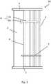
- Fig.1 shows a filter element 10 in a plan view from the raw gas side.
- the filter element 10 has a bellows 1 made of pleated filter medium and a functional space 2 directly adjacent to the bellows 1.
- the functional space 2 extends parallel to the folded edges of the bellows 1.
- the bellows 1 and the functional space 2 are separated from one another by an interface 4.
- Edge strips 3 are provided to stabilize and seal the bellows 1.
- the functional space 2 is located within the edge strips 3 and is firmly connected to the bellows 1 and is thus part of the filter element 10.
- Recesses 5a, 5b are provided in the interface 4 through which sensor elements 6a and scenting elements 7 can be introduced and pushed in, that this is in the area of the bellows 1 are located.
- Any sensor elements 6a and scenting elements 7 that may be present pierce the folding surfaces of the bellows 1, for which purpose recesses are also provided in the folding surfaces (not shown).
- a sensor element 6a and such a scenting element 7 are indicated with dashed lines.
- a sensor component 6b which is located in the functional space 2 or protrudes into it, is connected in one piece to the sensor element 6a. The sensor element 6a and the sensor component 6b together form a sensor 6.
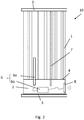
- Fig. 2 a second alternative arrangement of the functional space 2 relative to the bellows 1 is shown.
- the functional space 2 adjoins the bellows 1 on one side, namely where the end faces of the folded edges of the bellows 1 are located.
- the functional space 2 is separated from the bellows 1 by an interface 4.
- the functional space 2 lies within the boundaries of the edge strips 3.
- the boundary surface 4 can also be designed as edge strips 3.
- a sensor 6 and a fragrance element 7 can be seen.
- the sensor 6 is connected to a transmitter 8 which can transmit measurement data from the sensor 6 to a receiver (not shown).
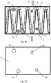
- the filter element 10 can also be equipped with several sensor elements 6a and several fragrance elements 7. This is in the Figures 3a and 3b shown.
- Fig. 3a shows a sectional view through the filter element 10 in the area of its bellows 1.
- An air flow L flows through the bellows 1.
- On the raw gas side a the air is still unfiltered, on the clean gas side b the air is already filtered.
- the filter element 10 has two sensor elements 6a and two fragrance elements 7.
- a first sensor element 6a is on the Raw gas side a and a second sensor element 6a arranged on the clean gas side b. This makes it possible to measure the air before and after filtering through the filter element 10.
- the scenting element 7 on the clean gas side (at b) serves to scent the air flow L directly
- the dosing substances with an oxidizing effect released by the raw gas side (at a) are used to clean the filter medium of the bellows 1, which leads to an extension of the filter life.
- the associated interface 4 is shown, which has two recesses 5a for the sensor elements 6a and two recesses 5b for the fragrance elements 7.
- the recesses 5a and 5b here have a circular or square basic shape.
- other shapes of the recesses 5a, 5b are also conceivable, for example also non-point-symmetrical shapes which allow sensor elements 6a and scenting elements 7 to be inserted only in a predetermined orientation.
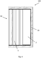
- a filter arrangement 100 is shown, wherein a filter element 10 is received by a frame 20.
- the filter element 10 has - as already stated above - a functional space 2. Any sensor elements 6a and fragrance elements 7 that may be present are not shown here for the sake of clarity. Since the functional space 2 is integrated into the filter element 10 and the external dimensions of the filter element 10 can remain unchanged despite the presence of the functional space 2, the filter element 10 can be easily installed in the frame 20 in existing machines and systems. The presence of the functional space 2 also does not result in any additional need for sealing between the filter element 10 and the frame 20.
- the additional functionalities of the filter element 10, which are provided by the sensor elements 6a and the fragrance elements 7 can be created without changing the system around the filter element 10, that is to say without changing the frame 20 and the filter arrangement 100.
Landscapes
- Chemical & Material Sciences (AREA)
- Chemical Kinetics & Catalysis (AREA)
- Engineering & Computer Science (AREA)
- Mechanical Engineering (AREA)
- Health & Medical Sciences (AREA)
- Animal Behavior & Ethology (AREA)
- Veterinary Medicine (AREA)
- Public Health (AREA)
- General Health & Medical Sciences (AREA)
- Life Sciences & Earth Sciences (AREA)
- Epidemiology (AREA)
- Computer Networks & Wireless Communication (AREA)
- Filtering Of Dispersed Particles In Gases (AREA)
- Disinfection, Sterilisation Or Deodorisation Of Air (AREA)
Abstract
Description
- Die Erfindung betrifft ein Filterelement mit einem Funktionsraum gemäß dem Oberbegriff von Anspruch 1.
- Aus der
WO 2007/093272 A1 ist ein Filterelement mit einem integrierten Behältnis bekannt. Das Behältnis kann dabei zur Aufnahme eines Beduftungselements dienen. Mit solchen Beduftungselementen kann ein Luftstrom im Filterelement mit einem bestimmten Duft versetzt werden. Auch aus derUS 2007/0261376 A1 und derEP 2 868 987 A1 gehen Filterelemente mit Beduftungselementen hervor. - Aus der
DE 10 2009 040 707 A1 , derWO 2016/016085 A1 und derUS 2003/0052791 A1 sind Filterelemente bekannt, die über Sensoren verfügen. Die Sensoren sind dabei direkt auf dem Filtermedium angebracht. - Aufgabe der vorliegenden Erfindung ist es ein Filterelement zu schaffen, welches einen Funktionsraum aufweist, welcher in einfacher Art und Weise das Vorsehen von mindestens einem Sensorelement und/ oder von mindestens einem Beduftungselement und einen einfachen Austausch der Beduftungselemente ermöglicht.
- Weitere Aufgabe ist es, eine Filteranordnung zu schaffen, welche einen einfachen Austausch eines Filterelements ermöglicht, insbesondere wenn das Filterelement ein wiederverwendbares Sensorelement umfasst.
- Gelöst wird diese Aufgabe durch ein Filterelement mit einem Funktionsraum mit den Merkmalen von Anspruch 1.
- Erfindungsgemäß wurde als vorteilhaft erkannt den Funktionsraum innerhalb der Kantenstreifen des Filterelements vorzusehen, sodass das Filterelement bei zusätzlicher Funktionalität kein größeres Volumen aufweist und in bestehenden Filteranordnungen Verwendung finden kann.
- Das erfindungsgemäße Filterelement besitzt einen Faltenbalg aus einem plissierten Filtermedium mit einer Vielzahl von Faltkanten und Faltflächen und besitzt Kantenstreifen zur Begrenzung des Filtermediums, sodass jeweils ein Kantenstreifen eine Wand des Filterelements bildet. Das Filterelement besitzt einen Funktionsraum, welcher fest mit dem Filterelement verbunden ist, an den Faltenbalg angrenzt und innerhalb der Kantenstreifen angeordnet ist. Eine Grenzfläche ist zwischen Faltenbalg und Funktionsraum angeordnet und trennt den Faltenbalg vom Funktionsraum. In vorteilhafter Weise ist die Grenzfläche mit mindestens einer Ausnehmung versehen, z.B. einer Aussparung oder einem Loch zur Aufnahme von Sensorelementen und/oder Beduftungselementen. Die Sensorelemente können dabei zur Messung von Partikeln, Gasen, Duftstoffen, etc. in einem Luftstrom durch das Filterelement dienen. Insbesondere sind die Sensorelemente und/oder Beduftungselemente in dem Filterelement nicht nur aufnehmbar sondern tatsächlich vorhanden und Teil des Filterelements.
- Die Ausnehmungen sind dabei derart ausgestaltet, dass ein Sensorkopf des Sensorelements oder das Beduftungselement im Bereich des Faltenbalgs positionierbar ist. Damit ausreichend Platz für die Sensorelemente und/oder Beduftungselemente besteht, kann der Faltenabstand und/oder die Faltenhöhe des Faltenbalgs eventuell lokal so verändert werden, dass mehr Platz für Sensorelemente bzw. Beduftungselemente geschaffen wird. Eventuell vorhandene Beduftungselemente sind bevorzugt reingasseitig des Faltenbalgs angeordnet, da die Duftstoffe so direkt in die gereinigte Luft abgegeben werden können.
- Das erfindungsgemäße Filterelement ist in vorteilhafter Weise besonders kompakt ausgestaltet und es wird eine einfache Bestückung mit Beduftungselementen bzw. Sensorelementen ermöglicht. Auch wird durch die Integration des Funktionsraumes in das Filterelement sichergestellt, dass die Anzahl möglicher Bypässe und damit die Gefahr von Fehlluft reduziert wird.
- In vorteilhafter Weiterbildung des erfindungsgemäßen Filterelements sind mindestens zwei Ausnehmungen in der Grenzfläche vorgesehen zur Aufnahme mindestens eines Sensorelements in einer Ausnehmung und mindestens eines Beduftungselements in einer anderen Ausnehmung. Bei dieser Ausgestaltung kann in vorteilhafter Weise sowohl eine Beduftung des Luftstroms durch das Filterelement erfolgen als auch eine Messung bestimmter Eigenschaften des Luftstroms. Alle dazu erforderlichen Elemente sind in das Filterelement integriert.
- In möglicher Ausgestaltung des erfindungsgemäßen Filterelements sind mindestens zwei Ausnehmungen in der Grenzfläche vorgesehen, zur Aufnahme von zwei Sensorelementen, wobei je eine Ausnehmung und damit auch je ein Sensorelement auf der Reingasseite und eine Ausnehmung und damit auch ein Sensorelement auf der Rohgasseite des Faltenbalgs positioniert ist. Dank einer derartigen Messung von Zuluft und Abluft sind Aussagen zur Luftqualität, Reinigungsleistung bzw. Filtrationsleistung, Lebensdauer des Filters, erforderlichem Filteraustausch, etc. möglich.
- In einer alternativen Ausgestaltung oder auch Weiterbildung des erfindungsgemäßen Filterelements ist mindestens eine Ausnehmung 5b in der Grenzfläche 4 vorgesehen zur Aufnahme von mindestens einem Beduftungselement 7, wobei die mindestens eine Ausnehmung 5b auf der Reingasseite b des Faltenbalgs 1 positioniert ist, sodass ein direktes Beduften des gereinigten Luftstroms mit Duftstoff ermöglicht wird.
- In einer alternativen Ausgestaltung oder auch Weiterbildung des erfindungsgemäßen Filterelements ist mindestens eine Ausnehmung 5b in der Grenzfläche 4 vorgesehen zur Aufnahme von mindestens einem Beduftungselement 7, wobei die mindestens eine Ausnehmung 5b auf der Rohgasseite a des Faltenbalgs 1 positioniert ist und das Beduftungselement einen Dosierstoff mit oxidierender Wirkung besitzt. Durch das rohgasseitige Beduftungselement kann ein Dosierstoff mit reinigender Wirkung für das Filtermedium des Faltenbalgs bereitgestellt werden.
- In einer alternativen Ausgestaltung oder auch Weiterbildung des erfindungsgemäßen Filterelements ist mindestens eine Ausnehmung 5b in der Grenzfläche 4 vorgesehen zur Aufnahme von mindestens einem Beduftungselement 7, wobei die mindestens eine Ausnehmung 5b auf der Reingasseite b des Faltenbalgs 1 positioniert ist und das Beduftungselement einen Dosierstoff mit oxidierender Wirkung besitzt. Durch das reingasseitige Beduftungselement kann ein Dosierstoff mit reinigender Wirkung für dem Filterelement nachgeschaltete Komponenten, wie. z.B. Luftleitungen, Wärmetauscher, Steuerungsklappen, usw. bereitgestellt werden.
- Bei Kombination dieser Ausgestaltungen ergibt sich ein Filterelement, bei welchem mindestens zwei Ausnehmungen in der Grenzfläche vorgesehen sind zur Aufnahme von zwei Beduftungselementen, wobei je ein Beduftungselement auf der Reingasseite und ein Beduftungselement auf der Rohgasseite des Faltenbalgs positioniert ist. Durch das reingasseitige Beduftungselement wird ein direktes Beduften des gereinigten Luftstroms mit Duftstoff ermöglicht. Durch das rohgasseitige Beduftungselement kann ein Dosierstoff für das Filtermedium des Faltenbalgs bereitgestellt werden. Durch ein weiteres reingasseitige Beduftungselement kann ein Dosierstoff mit reinigender Wirkung für dem Filterelement nachgeschaltete Komponenten bereitgestellt werden
- Überraschenderweise wurde gefunden, dass ein Dosierstoff mit oxidierender Wirkung, wie z.B. eine mit Silikaten angereicherte Natriumhypochloritlösung eine reinigende Wirkung auf das Filtermedium bzw auf nachgeschaltete Komponenten in Bezug auf Mikroorganismen und Viren haben kann, was zu einer Verlängerung der Filterlebensdauer des Filterelements bzw. zu einer Verhinderung einer "Verseuchung" der nachgeschaltete Komponenten führt.
- In vorteilhafter Ausgestaltung des erfindungsgemäßen Filterelements ist der Funktionsraum nur zu einer Seite hin geöffnet und ist damit nicht komplett abgeschlossen, sondern zugänglich. Insbesondere ist der Funktionsraum zur Rohgasseite hin geöffnet.
- In einer ersten möglichen Ausführungsvariante des Filterelements erstreckt sich der Funktionsraum parallel zu den Faltkanten des Faltenbalgs und die Faltflächen des Faltenbalgs werden von eventuell vorhandenen Sensorelementen und/oder Beduftungselementen durchstoßen. Dazu sind auch in den Faltflächen des Faltenbalgs entsprechende Ausnehmungen vorhanden. Die Grenzfläche des Filterelements kann dabei entweder aus dem Filtermedium ausgebildet oder als Kantenstreifen ausgeführt sein.
- Gemäß der zweiten Ausführungsvariante ist der Funktionsraum angrenzend an die Stirnflächen der Falkanten des Faltenbalgs positioniert und die Grenzfläche ist als Kantenstreifen ausgeführt. Bei dieser Ausführungsvariante können eventuell vorhandene Sensorelemente und/oder Beduftungselemente zwischen bzw. oberhalb von Faltflächen liegen, sodass die Faltflächen des Faltenbalgs ganz bleiben.
- In vorteilhafter Weiterbildung kann in dem Funktionsraum eine Sensorkomponente angeordnet sein, wobei die Sensorkomponente und das mindestens eine Sensorelement jeweils einen bzw. mehrere Sensoren ausbilden. So kann das Sensorelement im Wesentlichen den Messkopf umfassen und die Sensorkomponente die Ansteuerung und Stromversorgung des Sensorkopfes. Bei Sensorelement und Sensorkomponente kann es sich entweder um getrennte Elemente handeln. Sensorelement und Sensorkomponente können jedoch auch zu einem Bauteil zusammengefasst sein.
- In vorteilhafter Weiterbildung ist in dem Funktionsraum zusätzlich ein Sender angeordnet, der datenübertragungstechnisch mit dem Sensor verbunden ist zur Datenübertragung von Messdaten des Sensors. Die Messdaten des Sensors können so an einen Empfänger übertragen werden, welcher beispielsweise in einem Gehäuse des Filterelements angebracht ist, oder in der Anlage bzw. Maschine, in welcher das Filterelement zum Einsatz kommt. Insbesondere kann der Sender als NFC Sender, als Nearfield-Communication-Sender ausgebildet sein, z.B. unter Verwendung von RFID oder "Bluetooth".
- Die Erfindung betrifft auch eine Filteranordnung mit einem Rahmen und einem wie vorstehend beschriebenem Filterelement, wobei das Filterelement in den Rahmen aufgenommen ist. Unter Rahmen wird hierbei auch ein Gehäuse verstanden. Bei einer derartigen Ausgestaltung einer Filteranordnung wird in vorteilhafter Weise ein Funktionsraum innerhalb des Filterelements geschaffen. Der Rahmen muss nicht geändert werden und es besteht kein größerer Platzbedarf für das Filterelement. Auch wird keine zusätzliche Abdichtung des Funktionsraums zur Leckagevermeidung benötigt.
- Weiterhin betrifft die Erfindung auch die Verwendung einer solchen Filteranordnung zur Luftfiltration in einer mobilen Einrichtung, insbesondere in einem Kraftfahrzeug oder einem Nutzfahrzeug.
- Gegenstand der Erfindung ist auch ein Verfahren zur Steuerung eines Filtersystems mit einer wie obenstehend beschriebenen Filteranordnung. Das Filtersystem umfasst weiter eine Steuereinrichtung zur Ansteuerung des Filterelements, wobei die Steuereinrichtung datenübertragungstechnisch mit mindestens einem Sensor in dem Filterelement verbunden ist und die Ansteuerung des Filterelements abhängig von Messwerten des Sensors erfolgt. Beispielsweise kann die Ansteuerung des Filterelements die Steuerung des Volumenstroms, eine Ionisierung der Zuluft und eine Regulierung des Umluft-Frischluftanteils umfassen.
- Die beschriebene Erfindung und die beschriebenen vorteilhaften Weiterbildungen der Erfindung stellen auch in Kombination miteinander - soweit dies technisch sinnvoll ist - vorteilhafte Weiterbildungen der Erfindung dar.
- Hinsichtlich weiterer Vorteile und in konstruktiver und funktioneller Hinsicht vorteilhafter Ausgestaltungen der Erfindung wird auf die Unteransprüche sowie die Beschreibung von Ausführungsbeispielen unter Bezugnahme auf die beiliegenden Figuren verwiesen.
- Die Erfindung soll an Hand beigefügter Figuren noch näher erläutert werden. Einander entsprechende Elemente und Bauteile sind in den Figuren mit gleichen Bezugszeichen versehen. Zugunsten einer besseren Übersichtlichkeit der Figuren wurde auf eine maßstabsgetreue Darstellung verzichtet. Es zeigen in schematischer Darstellung
- Fig. 1
- eine erste Ausführungsvariante eines erfindungsgemäßen Filterelements
- Fig. 2
- eine zweite Ausführungsvariante eines erfindungsgemäßen Filterelements
- Fig. 3a
- ein Schnitt durch das Filterelement
- Fig. 3b
- eine Ansicht der Trennfläche
- Fig. 4
- eine Draufsicht einer Filteranordnung
-
Fig.1 zeigt ein Filterelement 10 in einer Draufsicht von der Rohgasseite her. Das Filterelement 10 besitzt einen Faltenbalg 1 aus plissiertem Filtermedium und direkt angrenzend an den Faltenbalg 1 einen Funktionsraum 2. Der Funktionsraum 2 erstreckt sich parallel zu den Faltkanten des Faltenbalgs 1. Der Faltenbalg 1 und der Funktionsraum 2 sind durch eine Grenzfläche 4 voneinander getrennt. Zur Stabilisierung und Abdichtung des Faltenbalgs 1 sind Kantenstreifen 3 vorgesehen. Der Funktionsraum 2 befindet sich innerhalb der Kantenstreifen 3 und ist fest mit dem Faltenbalg 1 verbunden und somit ein Teil des Filterelements 10. In der Grenzfläche 4 sind Ausnehmungen 5a, 5b vorgesehen, durch welche Sensorelemente 6a und Beduftungselemente 7 eingeführt und so eingeschoben werden können, dass sich diese im Bereich des Faltenbalgs 1 befinden. Eventuell vorhandene Sensorelemente 6a und Beduftungselemente 7 durchstoßen die Faltflächen den Faltenbalgs 1, wozu in den Faltflächen ebenfalls Ausnehmungen vorgesehen sind (nicht dargestellt). In der Darstellung vonFig. 1 ist ein solches Sensorelement 6a und ein solches Beduftungselement 7 mit gestrichelten Linien angedeutet. Einteilig mit dem Sensorelement 6a ist eine Sensorkomponente 6b verbunden, welche sich im Funktionsraum 2 befindet bzw. in diesen hineinragt. Das Sensorelement 6a und die Sensorkomponente 6b bilden zusammen einen Sensor 6 aus. - In
Fig. 2 ist eine zweite alternative Anordnung des Funktionsraums 2 relativ zum Faltenbalg 1 dargestellt. Der Funktionsraum 2 grenzt an einer Seite an den Faltenbalg 1 an, nämlich dort, wo sich die Stirnflächen der Faltkanten des Faltenbalgs1 befinden. Durch eine Grenzfläche 4 wird der Funktionsraum 2 vom Faltenbalg 1 getrennt. Auch hier liegt der Funktionsraum 2 innerhalb der Grenzen der Kantenstreifen 3. Auch die Grenzfläche 4 kann als Kantenstreifen 3 ausgeführt sein. In der Draufsicht vonFig. 2 ist ein Sensor 6 und ein Beduftungselement 7 zu erkennen. Der Sensor 6 ist datenübertragungstechnisch mit einem Sender 8 verbunden, welcher Messdaten des Sensors 6 zu einem nicht dargestellten Empfänger übertragen kann. - Während in den
Fig. 1 und2 jeweils nur ein Beduftungselement und ein - Sensorelement dargestellt waren, kann das Filterelement 10 auch mit mehreren Sensorelementen 6a und mehreren Beduftungselementen 7 bestückt sein. Dies ist in denFig. 3a und 3b dargestellt. -
Fig. 3a zeigt eine Schnittdarstellung durch das Filterelement 10 im Bereich seines Faltenbalgs 1. Der Faltenbalg 1 wird von einem Luftstrom L durchströmt. Auf der Rohgasseite a ist die Luft noch ungefiltert, auf der Reingasseite b ist die Luft bereits gefiltert. Das Filterelement 10 besitzt zwei Sensorelemente 6a und zwei Beduftungselemente 7. Ein erstes Sensorelement 6a ist auf der Rohgasseite a und ein zweites Sensorelement 6a auf der Reingasseite b angeordnet. Dadurch wird ermöglicht, die Luft vor und nach der Filterung durch das Filterelement 10 zu messen. Während das reingasseitige Beduftungselement 7 (bei b) einer direkten Beduftung des Luftstroms L dient, dienen die von dem rohgasseitigen (bei a) positionierten Beduftungselement 7 freigegebenen Dosierstoffe mit oxidierender Wirkung einer Reinigung des Filtermediums des Faltenbalgs 1, was zu einer Verlängerung der Filterlebensdauer führt. - In
Fig. 3b ist die zugehörige Grenzfläche 4 dargestellt, welche über zwei Ausnehmungen 5a für die Sensorelemente 6a und über zwei Ausnehmungen 5b für die Beduftungselemente 7 verfügt. Die Ausnehmungen 5a bzw. 5b haben hier eine kreisförmige bzw. quadratische Grundform. Es sind jedoch auch andere Formen der Ausnehmungen 5a, 5b denkbar, beispielsweise auch nicht-punktsymmetrische Formen, welche ein Einschieben von Sensorelementen 6a und Beduftungselementen 7 nur in einer vorgegebenen Orientierung ermöglichen. - In
Fig. 4 ist eine Filteranordnung 100 dargestellt, wobei ein Filterelement 10 von einem Rahmen 20 aufgenommen wird. Das Filterelement 10 besitzt - wie bereits obenstehend ausgeführt wird - einen Funktionsraum 2. Eventuelle vorhandene Sensorelemente 6a und Beduftungselemente 7 sind hier der besseren Übersichtlichkeit halber nicht dargestellt. Da der Funktionsraum 2 in das Filterelement 10 integriert ist und die Außenabmaße des Filterelements 10 trotz dem Vorhandensein des Funktionsraumes 2 unverändert bleiben können, kann das Filterelement 10 problemlos in Rahmen 20 in bestehende Maschinen und Anlagen montiert werden. Auch ergibt sich durch das Vorhandensein des Funktionsraums 2 kein zusätzliches Abdichtbedürfnis zwischen Filterelement 10 und Rahmen 20. Die zusätzlichen Funktionalitäten des Filterelements 10, welche durch die Sensorelemente 6a und die Beduftungselemente 7 geschaffen werden, können also ohne eine Veränderung des Systems um das Filterelement 10 herum, sprich ohne Veränderungen von Rahmen 20 und Filteranordnung 100 erfolgen. -
- 1
- Faltenbalg aus plissiertem Filtermedium
- 2
- Funktionsraum
- 3
- Kantenstreifen
- 4
- Grenzfläche
- 5a
- Ausnehmung Sensorelement
- 5b
- Ausnehmung Beduftungselement
- 6
- Sensor
- 6a
- Sensorelement
- 6b
- Sensorkomponente
- 7
- Beduftungselement
- 8
- Sender
- 9
- -
- 10
- Filterelement
- 20
- Rahmen
- 100
- Filteranordnung
- a
- Rohgasseite
- b
- Reingasseite
- L
- Luftstrom
Claims (13)
- Filterelement(10) mit einem Faltenbalg (1) aus einem plissierten Filtermedium und Kantenstreifen (3) zur Begrenzung des Faltenbalgs (1) wobei das Filterelement (10) einen Funktionsraum (2) besitzt, welcher an den Faltenbalg (1) angrenzt und innerhalb der Kantenstreifen (3) angeordnet ist, mit einer Grenzfläche (4) zwischen Faltenbalg (1) und Funktionsraum (2),
dadurch gekennzeichnet,
dass die Grenzfläche (4) mit mindestens einer Ausnehmung (5a, 5b) versehen ist zur Aufnahme von Sensorelementen (6a) und/oder von Beduftungselementen (7). - Filterelement nach Anspruch 1 dadurch gekennzeichnet,
dass mindestens zwei Ausnehmungen (5a, 5b) in der Grenzfläche (4) vorgesehen sind zur Aufnahme mindestens eines Sensorelements (6a) und mindestens eines Beduftungselements (7). - Filterelement nach einem der vorangehenden Ansprüche dadurch gekennzeichnet,
dass mindestens zwei Ausnehmungen (5a) in der Grenzfläche (4) vorgesehen sind zur Aufnahme von mindestens zwei Sensorelementen (6a), wobei mindestens je eine Ausnehmung (5a) auf der Reingasseite (b) undeine Ausnehmung (5a) auf der Rohgasseite (a) des Faltenbalgs (1) positioniert ist. - Filterelement nach einem der vorangehenden Ansprüche dadurch gekennzeichnet,- dass mindestens eine Ausnehmung (5b) in der Grenzfläche (4) vorgesehen ist zur Aufnahme von mindestens einem Beduftungselement (7), wobei die mindestens eine Ausnehmung (5b) auf der Reingasseite (b) des Faltenbalgs (1) positioniert ist, und/oder- dass mindestens eine Ausnehmung (5b) in der Grenzfläche (4) vorgesehen ist zur Aufnahme von mindestens einem Beduftungselement (7), wobei die mindestens eine Ausnehmung (5b) auf der Rohgasseite (a) des Faltenbalgs (1) positioniert ist und das Beduftungselement einen Dosierstoff mit oxidierender Wirkung besitzt, und/oder- dass mindestens eine Ausnehmung (5b) in der Grenzfläche (4) vorgesehen ist zur Aufnahme von mindestens einem Beduftungselement (7), wobei die mindestens eine Ausnehmung (5b) auf der Reingasseite (b) des Faltenbalgs (1) positioniert ist und das Beduftungselement einen Dosierstoff mit oxidierender Wirkung besitzt.
- Filterelement nach einem der vorangehenden Ansprüche dadurch gekennzeichnet,
dass der Funktionsraum (2) nur zu einer Seite hin geöffnet ist, insbesondere zur Rohgasseite (a) hin. - Filterelement nach einem der vorangehenden Ansprüche dadurch gekennzeichnet,
dass sich der Funktionsraum (2) parallel zu den Faltkanten des Faltenbalgs (1) erstreckt und die Faltflächen von Sensorelementen (6a) und /oder Beduftungselementen (7) durchstoßen werden. - Filterelement nach Anspruch 6 dadurch gekennzeichnet,
dass die Grenzfläche (4) aus Filtermedium gebildet wird oder als Kantenstreifen (3) ausgeführt ist. - Filterelement nach einem der Ansprüche 1 bis 5 dadurch gekennzeichnet,
dass der Funktionsraum (2) angrenzend an die Stirnflächen der Faltkanten des Faltenbalgs (1) positioniert ist und die Grenzfläche (4) als Kantenstreifen (3) ausgeführt ist. - Filterelement nach einem der vorangehenden Ansprüche dadurch gekennzeichnet,
dass in dem Funktionsraum (4) eine Sensorkomponente (6b) angeordnet ist, wobei die Sensorkomponente (6b) und das Sensorelement (6a) einen Sensor (6) bilden. - Filterelement nach Anspruch 9 dadurch gekennzeichnet,
dass in dem Funktionsraum (2) ein Sender (8) angeordnet ist, der datenübertragungstechnisch mit dem Sensor (6) verbunden ist zur Datenübertragung von Messdaten des Sensors (6). - Filteranordnung (100) mit einem Rahmen (20) und einem Filterelement (10) nach einem der vorangehenden Ansprüche, wobei das Filterelement (10) in dem Rahmen (20) aufgenommen ist.
- Verwendung einer Filteranordnung (100) nach Anspruch 11 zur Luftfiltration in einer mobilen Einrichtung, insbesondere in einem Kraftfahrzeug oder einem Nutzfahrzeug.
- Verfahren zur Steuerung eines Filtersystems mit einer Filteranordnung (100) nach Anspruch 11 und einer Steuereinrichtung zur Ansteuerung des Filterelements (10), wobei die Steuereinrichtung datenübertragungstechnisch mit mindestens einem Sensor (6) in dem Filterelement (10) verbunden ist und die Ansteuerung des Filterelements (10) abhängig von Messwerten des Sensors (6) erfolgt.
Priority Applications (3)
| Application Number | Priority Date | Filing Date | Title |
|---|---|---|---|
| EP19188126.7A EP3769833B1 (de) | 2019-07-24 | 2019-07-24 | Filterelement mit funktionsraum und filteranordnung mit solchem filterelement und verfahren zur steuerung eines filtersystems |
| CN202010655018.0A CN112295339A (zh) | 2019-07-24 | 2020-07-09 | 具有功能空间的过滤元件和具有这种过滤元件的过滤装置 |
| US16/928,014 US20210023494A1 (en) | 2019-07-24 | 2020-07-14 | Filter element having a functional space and filter arrangement having such a filter element, and method for controlling a filter system |
Applications Claiming Priority (1)
| Application Number | Priority Date | Filing Date | Title |
|---|---|---|---|
| EP19188126.7A EP3769833B1 (de) | 2019-07-24 | 2019-07-24 | Filterelement mit funktionsraum und filteranordnung mit solchem filterelement und verfahren zur steuerung eines filtersystems |
Publications (2)
| Publication Number | Publication Date |
|---|---|
| EP3769833A1 true EP3769833A1 (de) | 2021-01-27 |
| EP3769833B1 EP3769833B1 (de) | 2022-04-20 |
Family
ID=67438738
Family Applications (1)
| Application Number | Title | Priority Date | Filing Date |
|---|---|---|---|
| EP19188126.7A Active EP3769833B1 (de) | 2019-07-24 | 2019-07-24 | Filterelement mit funktionsraum und filteranordnung mit solchem filterelement und verfahren zur steuerung eines filtersystems |
Country Status (3)
| Country | Link |
|---|---|
| US (1) | US20210023494A1 (de) |
| EP (1) | EP3769833B1 (de) |
| CN (1) | CN112295339A (de) |
Families Citing this family (1)
| Publication number | Priority date | Publication date | Assignee | Title |
|---|---|---|---|---|
| EP3865199B1 (de) * | 2020-02-12 | 2023-09-13 | Carl Freudenberg KG | Filtermodul mit sensor zur bestimmung des beladungszustandes und verfahren zum bestimmen des beladungszustandes |
Citations (8)
| Publication number | Priority date | Publication date | Assignee | Title |
|---|---|---|---|---|
| US20030052791A1 (en) | 2001-08-17 | 2003-03-20 | Heinz Reinhardt | Method and device for monitoring the service life of a filter |
| KR20070068955A (ko) * | 2005-12-27 | 2007-07-02 | 현대모비스 주식회사 | 에어필터용 적외선센서 장착구조 |
| WO2007093272A1 (de) | 2006-02-15 | 2007-08-23 | Carl Freudenberg Kg | Filterelement mit einem stoff zur beduftung und/oder reinigung |
| US20070261376A1 (en) | 2004-07-01 | 2007-11-15 | Valeo Systemes Thermiques | Air Treatment Device Used in a Particle Filter or a Combined Filter for a Heating, Ventilation and/or Air Conditioning Installation for a Vehicle Cabin |
| DE102009040707A1 (de) | 2009-09-10 | 2011-04-21 | Carl Freudenberg Kg | Filterelement mit einem fest angebundenen Sensor |
| DE102012019332A1 (de) * | 2012-10-02 | 2014-04-03 | Bayerische Motoren Werke Aktiengesellschaft | System zur Einbringung von Duftstoffen in den Innenraum eines Fahrzeugs |
| EP2868987A1 (de) | 2013-07-29 | 2015-05-06 | Carl Freudenberg KG | Filterkonstruktion sowie diese umfassendes Filtersystem |
| WO2016016085A1 (de) | 2014-08-01 | 2016-02-04 | Carl Freudenberg Kg | Sensor, filterelement mit einem sensor und verwendung eines solchen filterelements |
Family Cites Families (13)
| Publication number | Priority date | Publication date | Assignee | Title |
|---|---|---|---|---|
| US3699749A (en) * | 1971-05-18 | 1972-10-24 | Raymond M Nowicki | Automobile carburator air intake filters |
| US5192346A (en) * | 1992-07-22 | 1993-03-09 | Thaddeus Kowalczyk | Air purifier pleated filter to stop pollution for passenger inside of the motor vehicle |
| US5753343A (en) * | 1992-08-04 | 1998-05-19 | Minnesota Mining And Manufacturing Company | Corrugated nonwoven webs of polymeric microfiber |
| KR100470632B1 (ko) * | 2002-11-02 | 2005-02-21 | 기아자동차주식회사 | 차량용 에어컨 필터 구조 |
| US7749303B2 (en) * | 2007-08-30 | 2010-07-06 | The Boeing Company | Service life indicator for chemical filters |
| DE102008022630B4 (de) * | 2008-05-08 | 2015-12-31 | Bayerische Motoren Werke Aktiengesellschaft | Fahrzeugklimaanlage mit einem Filterelement mit Feuchtesensor und Verfahren zum Betreiben einer Fahrzeugklimaanlage |
| US9504945B2 (en) * | 2009-06-12 | 2016-11-29 | Clarcor Air Filtration Products | Air cooling system incorporating membrane-free filter and/or integral framing for filter |
| WO2011121644A1 (ja) * | 2010-03-30 | 2011-10-06 | サンデン株式会社 | 車両空調装置用フィルター |
| DE202012012812U1 (de) * | 2011-06-21 | 2013-12-16 | Carl Freudenberg Kg | Filterelement mit Fûhrungsschächten |
| CN104524896B (zh) * | 2014-12-29 | 2017-07-04 | 东莞市宇洁新材料有限公司 | 一种可检测颗粒物过滤器寿命的室内空气净化装置及其检测方法 |
| CN105854453B (zh) * | 2016-03-30 | 2018-09-14 | 刘晓冰 | 抗病型空气净化器用过滤装置及其安装和使用方法 |
| CN107261658A (zh) * | 2017-06-30 | 2017-10-20 | 苏州瓷气时代净化设备有限公司 | 一种智能化洁净型空气净化设备 |
| US11779870B2 (en) * | 2020-12-04 | 2023-10-10 | Mahle International Gmbh | Smart filter elements and systems |
-
2019
- 2019-07-24 EP EP19188126.7A patent/EP3769833B1/de active Active
-
2020
- 2020-07-09 CN CN202010655018.0A patent/CN112295339A/zh active Pending
- 2020-07-14 US US16/928,014 patent/US20210023494A1/en not_active Abandoned
Patent Citations (8)
| Publication number | Priority date | Publication date | Assignee | Title |
|---|---|---|---|---|
| US20030052791A1 (en) | 2001-08-17 | 2003-03-20 | Heinz Reinhardt | Method and device for monitoring the service life of a filter |
| US20070261376A1 (en) | 2004-07-01 | 2007-11-15 | Valeo Systemes Thermiques | Air Treatment Device Used in a Particle Filter or a Combined Filter for a Heating, Ventilation and/or Air Conditioning Installation for a Vehicle Cabin |
| KR20070068955A (ko) * | 2005-12-27 | 2007-07-02 | 현대모비스 주식회사 | 에어필터용 적외선센서 장착구조 |
| WO2007093272A1 (de) | 2006-02-15 | 2007-08-23 | Carl Freudenberg Kg | Filterelement mit einem stoff zur beduftung und/oder reinigung |
| DE102009040707A1 (de) | 2009-09-10 | 2011-04-21 | Carl Freudenberg Kg | Filterelement mit einem fest angebundenen Sensor |
| DE102012019332A1 (de) * | 2012-10-02 | 2014-04-03 | Bayerische Motoren Werke Aktiengesellschaft | System zur Einbringung von Duftstoffen in den Innenraum eines Fahrzeugs |
| EP2868987A1 (de) | 2013-07-29 | 2015-05-06 | Carl Freudenberg KG | Filterkonstruktion sowie diese umfassendes Filtersystem |
| WO2016016085A1 (de) | 2014-08-01 | 2016-02-04 | Carl Freudenberg Kg | Sensor, filterelement mit einem sensor und verwendung eines solchen filterelements |
Also Published As
| Publication number | Publication date |
|---|---|
| CN112295339A (zh) | 2021-02-02 |
| US20210023494A1 (en) | 2021-01-28 |
| EP3769833B1 (de) | 2022-04-20 |
Similar Documents
| Publication | Publication Date | Title |
|---|---|---|
| DE102013002057B4 (de) | Filtereinrichtung, insbesondere Luftfilter | |
| EP1128898B1 (de) | Verfahren zur herstellung eines membranmoduls | |
| EP2654922B1 (de) | Luftfilterelement | |
| DE4430333A1 (de) | Filter | |
| WO2002062447A1 (de) | Filtervorrichtung | |
| EP2207609A1 (de) | Filtervorrichtung | |
| DE19809989A1 (de) | Ventil für eine Filteranordnung und ein Verfahren zu dessen Herstellung | |
| DE102010029591A1 (de) | Filtereinrichtung für hochviskose Medien | |
| DE102006039952B4 (de) | Luftfilter | |
| EP3769833B1 (de) | Filterelement mit funktionsraum und filteranordnung mit solchem filterelement und verfahren zur steuerung eines filtersystems | |
| EP2397211B1 (de) | Innenraumluftfilterelement, Filteraufnahme, Filteranordnung und Verfahren zum Herstellen des Innenraumluftfilterelements | |
| EP3037150B1 (de) | Filtereinrichtung | |
| DE10026451A1 (de) | Flüssigkeitsfilter | |
| EP2808071B1 (de) | Filtereinrichtung, insbesondere für ein Kraftfahrzeug | |
| EP3680003A1 (de) | Filterpatrone mit venturi-düse | |
| EP2749335B1 (de) | Zweiteiliger Partikelfilter | |
| DE102013002729A1 (de) | Druckluft-Wartungsgerät zum Filtern von Druckluft sowie Verfahren zum Wechseln einer Filterpatrone | |
| EP2461887A1 (de) | Filtereinrichtung und wickelfilterelement | |
| DE102018219062B4 (de) | Luftfilter und eine Belüftungseinrichtung mit dem Luftfilter | |
| DE202006004529U1 (de) | Filtereinsatz mit Verschluss für zweite Filterkammer | |
| WO2009052911A1 (de) | Innenraumfilter für eine heizungs- oder klimaanlage eines kraftwagens | |
| DE102015007182A1 (de) | Filterelement und Filtersystem | |
| DE112009000298B4 (de) | Filtereinrichtung, insbesondere Luftfilter für Brennkraftmaschinen | |
| EP4115964B1 (de) | Filtervorrichtung | |
| DE102007004491A1 (de) | Filterelement zur Abreinigung von Fluiden |
Legal Events
| Date | Code | Title | Description |
|---|---|---|---|
| PUAI | Public reference made under article 153(3) epc to a published international application that has entered the european phase |
Free format text: ORIGINAL CODE: 0009012 |
|
| STAA | Information on the status of an ep patent application or granted ep patent |
Free format text: STATUS: THE APPLICATION HAS BEEN PUBLISHED |
|
| AK | Designated contracting states |
Kind code of ref document: A1 Designated state(s): AL AT BE BG CH CY CZ DE DK EE ES FI FR GB GR HR HU IE IS IT LI LT LU LV MC MK MT NL NO PL PT RO RS SE SI SK SM TR |
|
| AX | Request for extension of the european patent |
Extension state: BA ME |
|
| STAA | Information on the status of an ep patent application or granted ep patent |
Free format text: STATUS: REQUEST FOR EXAMINATION WAS MADE |
|
| 17P | Request for examination filed |
Effective date: 20210512 |
|
| RBV | Designated contracting states (corrected) |
Designated state(s): AL AT BE BG CH CY CZ DE DK EE ES FI FR GB GR HR HU IE IS IT LI LT LU LV MC MK MT NL NO PL PT RO RS SE SI SK SM TR |
|
| STAA | Information on the status of an ep patent application or granted ep patent |
Free format text: STATUS: EXAMINATION IS IN PROGRESS |
|
| 17Q | First examination report despatched |
Effective date: 20210707 |
|
| GRAP | Despatch of communication of intention to grant a patent |
Free format text: ORIGINAL CODE: EPIDOSNIGR1 |
|
| STAA | Information on the status of an ep patent application or granted ep patent |
Free format text: STATUS: GRANT OF PATENT IS INTENDED |
|
| INTG | Intention to grant announced |
Effective date: 20220107 |
|
| RIN1 | Information on inventor provided before grant (corrected) |
Inventor name: STAHL, ULRICH Inventor name: BRAEUNLING, VOLKER Inventor name: OELSNER, ALEXANDER |
|
| GRAS | Grant fee paid |
Free format text: ORIGINAL CODE: EPIDOSNIGR3 |
|
| GRAA | (expected) grant |
Free format text: ORIGINAL CODE: 0009210 |
|
| STAA | Information on the status of an ep patent application or granted ep patent |
Free format text: STATUS: THE PATENT HAS BEEN GRANTED |
|
| AK | Designated contracting states |
Kind code of ref document: B1 Designated state(s): AL AT BE BG CH CY CZ DE DK EE ES FI FR GB GR HR HU IE IS IT LI LT LU LV MC MK MT NL NO PL PT RO RS SE SI SK SM TR |
|
| REG | Reference to a national code |
Ref country code: GB Ref legal event code: FG4D Free format text: NOT ENGLISH |
|
| REG | Reference to a national code |
Ref country code: CH Ref legal event code: EP |
|
| REG | Reference to a national code |
Ref country code: IE Ref legal event code: FG4D Free format text: LANGUAGE OF EP DOCUMENT: GERMAN |
|
| REG | Reference to a national code |
Ref country code: DE Ref legal event code: R096 Ref document number: 502019004099 Country of ref document: DE |
|
| REG | Reference to a national code |
Ref country code: AT Ref legal event code: REF Ref document number: 1484730 Country of ref document: AT Kind code of ref document: T Effective date: 20220515 |
|
| REG | Reference to a national code |
Ref country code: LT Ref legal event code: MG9D |
|
| REG | Reference to a national code |
Ref country code: NL Ref legal event code: MP Effective date: 20220420 |
|
| PG25 | Lapsed in a contracting state [announced via postgrant information from national office to epo] |
Ref country code: NL Free format text: LAPSE BECAUSE OF FAILURE TO SUBMIT A TRANSLATION OF THE DESCRIPTION OR TO PAY THE FEE WITHIN THE PRESCRIBED TIME-LIMIT Effective date: 20220420 |
|
| PG25 | Lapsed in a contracting state [announced via postgrant information from national office to epo] |
Ref country code: SE Free format text: LAPSE BECAUSE OF FAILURE TO SUBMIT A TRANSLATION OF THE DESCRIPTION OR TO PAY THE FEE WITHIN THE PRESCRIBED TIME-LIMIT Effective date: 20220420 Ref country code: PT Free format text: LAPSE BECAUSE OF FAILURE TO SUBMIT A TRANSLATION OF THE DESCRIPTION OR TO PAY THE FEE WITHIN THE PRESCRIBED TIME-LIMIT Effective date: 20220822 Ref country code: NO Free format text: LAPSE BECAUSE OF FAILURE TO SUBMIT A TRANSLATION OF THE DESCRIPTION OR TO PAY THE FEE WITHIN THE PRESCRIBED TIME-LIMIT Effective date: 20220720 Ref country code: LT Free format text: LAPSE BECAUSE OF FAILURE TO SUBMIT A TRANSLATION OF THE DESCRIPTION OR TO PAY THE FEE WITHIN THE PRESCRIBED TIME-LIMIT Effective date: 20220420 Ref country code: HR Free format text: LAPSE BECAUSE OF FAILURE TO SUBMIT A TRANSLATION OF THE DESCRIPTION OR TO PAY THE FEE WITHIN THE PRESCRIBED TIME-LIMIT Effective date: 20220420 Ref country code: GR Free format text: LAPSE BECAUSE OF FAILURE TO SUBMIT A TRANSLATION OF THE DESCRIPTION OR TO PAY THE FEE WITHIN THE PRESCRIBED TIME-LIMIT Effective date: 20220721 Ref country code: FI Free format text: LAPSE BECAUSE OF FAILURE TO SUBMIT A TRANSLATION OF THE DESCRIPTION OR TO PAY THE FEE WITHIN THE PRESCRIBED TIME-LIMIT Effective date: 20220420 Ref country code: ES Free format text: LAPSE BECAUSE OF FAILURE TO SUBMIT A TRANSLATION OF THE DESCRIPTION OR TO PAY THE FEE WITHIN THE PRESCRIBED TIME-LIMIT Effective date: 20220420 Ref country code: BG Free format text: LAPSE BECAUSE OF FAILURE TO SUBMIT A TRANSLATION OF THE DESCRIPTION OR TO PAY THE FEE WITHIN THE PRESCRIBED TIME-LIMIT Effective date: 20220720 |
|
| PG25 | Lapsed in a contracting state [announced via postgrant information from national office to epo] |
Ref country code: RS Free format text: LAPSE BECAUSE OF FAILURE TO SUBMIT A TRANSLATION OF THE DESCRIPTION OR TO PAY THE FEE WITHIN THE PRESCRIBED TIME-LIMIT Effective date: 20220420 Ref country code: PL Free format text: LAPSE BECAUSE OF FAILURE TO SUBMIT A TRANSLATION OF THE DESCRIPTION OR TO PAY THE FEE WITHIN THE PRESCRIBED TIME-LIMIT Effective date: 20220420 Ref country code: LV Free format text: LAPSE BECAUSE OF FAILURE TO SUBMIT A TRANSLATION OF THE DESCRIPTION OR TO PAY THE FEE WITHIN THE PRESCRIBED TIME-LIMIT Effective date: 20220420 Ref country code: IS Free format text: LAPSE BECAUSE OF FAILURE TO SUBMIT A TRANSLATION OF THE DESCRIPTION OR TO PAY THE FEE WITHIN THE PRESCRIBED TIME-LIMIT Effective date: 20220820 |
|
| REG | Reference to a national code |
Ref country code: DE Ref legal event code: R097 Ref document number: 502019004099 Country of ref document: DE |
|
| PG25 | Lapsed in a contracting state [announced via postgrant information from national office to epo] |
Ref country code: SM Free format text: LAPSE BECAUSE OF FAILURE TO SUBMIT A TRANSLATION OF THE DESCRIPTION OR TO PAY THE FEE WITHIN THE PRESCRIBED TIME-LIMIT Effective date: 20220420 Ref country code: SK Free format text: LAPSE BECAUSE OF FAILURE TO SUBMIT A TRANSLATION OF THE DESCRIPTION OR TO PAY THE FEE WITHIN THE PRESCRIBED TIME-LIMIT Effective date: 20220420 Ref country code: RO Free format text: LAPSE BECAUSE OF FAILURE TO SUBMIT A TRANSLATION OF THE DESCRIPTION OR TO PAY THE FEE WITHIN THE PRESCRIBED TIME-LIMIT Effective date: 20220420 Ref country code: EE Free format text: LAPSE BECAUSE OF FAILURE TO SUBMIT A TRANSLATION OF THE DESCRIPTION OR TO PAY THE FEE WITHIN THE PRESCRIBED TIME-LIMIT Effective date: 20220420 Ref country code: DK Free format text: LAPSE BECAUSE OF FAILURE TO SUBMIT A TRANSLATION OF THE DESCRIPTION OR TO PAY THE FEE WITHIN THE PRESCRIBED TIME-LIMIT Effective date: 20220420 Ref country code: CZ Free format text: LAPSE BECAUSE OF FAILURE TO SUBMIT A TRANSLATION OF THE DESCRIPTION OR TO PAY THE FEE WITHIN THE PRESCRIBED TIME-LIMIT Effective date: 20220420 |
|
| PLBE | No opposition filed within time limit |
Free format text: ORIGINAL CODE: 0009261 |
|
| STAA | Information on the status of an ep patent application or granted ep patent |
Free format text: STATUS: NO OPPOSITION FILED WITHIN TIME LIMIT |
|
| PG25 | Lapsed in a contracting state [announced via postgrant information from national office to epo] |
Ref country code: MC Free format text: LAPSE BECAUSE OF FAILURE TO SUBMIT A TRANSLATION OF THE DESCRIPTION OR TO PAY THE FEE WITHIN THE PRESCRIBED TIME-LIMIT Effective date: 20220420 |
|
| REG | Reference to a national code |
Ref country code: CH Ref legal event code: PL |
|
| 26N | No opposition filed |
Effective date: 20230123 |
|
| REG | Reference to a national code |
Ref country code: BE Ref legal event code: MM Effective date: 20220731 |
|
| PG25 | Lapsed in a contracting state [announced via postgrant information from national office to epo] |
Ref country code: AL Free format text: LAPSE BECAUSE OF FAILURE TO SUBMIT A TRANSLATION OF THE DESCRIPTION OR TO PAY THE FEE WITHIN THE PRESCRIBED TIME-LIMIT Effective date: 20220420 |
|
| PG25 | Lapsed in a contracting state [announced via postgrant information from national office to epo] |
Ref country code: LU Free format text: LAPSE BECAUSE OF NON-PAYMENT OF DUE FEES Effective date: 20220724 Ref country code: LI Free format text: LAPSE BECAUSE OF NON-PAYMENT OF DUE FEES Effective date: 20220731 Ref country code: FR Free format text: LAPSE BECAUSE OF NON-PAYMENT OF DUE FEES Effective date: 20220731 Ref country code: CH Free format text: LAPSE BECAUSE OF NON-PAYMENT OF DUE FEES Effective date: 20220731 |
|
| PG25 | Lapsed in a contracting state [announced via postgrant information from national office to epo] |
Ref country code: SI Free format text: LAPSE BECAUSE OF FAILURE TO SUBMIT A TRANSLATION OF THE DESCRIPTION OR TO PAY THE FEE WITHIN THE PRESCRIBED TIME-LIMIT Effective date: 20220420 Ref country code: BE Free format text: LAPSE BECAUSE OF NON-PAYMENT OF DUE FEES Effective date: 20220731 |
|
| P01 | Opt-out of the competence of the unified patent court (upc) registered |
Effective date: 20230503 |
|
| PG25 | Lapsed in a contracting state [announced via postgrant information from national office to epo] |
Ref country code: IE Free format text: LAPSE BECAUSE OF NON-PAYMENT OF DUE FEES Effective date: 20220724 |
|
| PGFP | Annual fee paid to national office [announced via postgrant information from national office to epo] |
Ref country code: DE Payment date: 20230724 Year of fee payment: 5 |
|
| PG25 | Lapsed in a contracting state [announced via postgrant information from national office to epo] |
Ref country code: IT Free format text: LAPSE BECAUSE OF FAILURE TO SUBMIT A TRANSLATION OF THE DESCRIPTION OR TO PAY THE FEE WITHIN THE PRESCRIBED TIME-LIMIT Effective date: 20220420 |
|
| GBPC | Gb: european patent ceased through non-payment of renewal fee |
Effective date: 20230724 |
|
| PG25 | Lapsed in a contracting state [announced via postgrant information from national office to epo] |
Ref country code: MK Free format text: LAPSE BECAUSE OF FAILURE TO SUBMIT A TRANSLATION OF THE DESCRIPTION OR TO PAY THE FEE WITHIN THE PRESCRIBED TIME-LIMIT Effective date: 20220420 Ref country code: CY Free format text: LAPSE BECAUSE OF FAILURE TO SUBMIT A TRANSLATION OF THE DESCRIPTION OR TO PAY THE FEE WITHIN THE PRESCRIBED TIME-LIMIT Effective date: 20220420 Ref country code: GB Free format text: LAPSE BECAUSE OF NON-PAYMENT OF DUE FEES Effective date: 20230724 |