EP3769793B1 - Method for producing sterile receptacles and bottling plant comprising said producing apparatus - Google Patents
Method for producing sterile receptacles and bottling plant comprising said producing apparatus Download PDFInfo
- Publication number
- EP3769793B1 EP3769793B1 EP20185560.8A EP20185560A EP3769793B1 EP 3769793 B1 EP3769793 B1 EP 3769793B1 EP 20185560 A EP20185560 A EP 20185560A EP 3769793 B1 EP3769793 B1 EP 3769793B1
- Authority
- EP
- European Patent Office
- Prior art keywords
- parisons
- unit
- moulding
- neck
- thermal conditioning
- Prior art date
- Legal status (The legal status is an assumption and is not a legal conclusion. Google has not performed a legal analysis and makes no representation as to the accuracy of the status listed.)
- Active
Links
- 238000004519 manufacturing process Methods 0.000 title claims description 13
- 230000001954 sterilising effect Effects 0.000 claims description 27
- 238000000465 moulding Methods 0.000 claims description 26
- 238000004659 sterilization and disinfection Methods 0.000 claims description 23
- 230000003750 conditioning effect Effects 0.000 claims description 18
- 238000007664 blowing Methods 0.000 claims description 16
- 239000012815 thermoplastic material Substances 0.000 claims description 5
- 239000008187 granular material Substances 0.000 claims description 4
- 238000000926 separation method Methods 0.000 claims description 4
- 238000000034 method Methods 0.000 claims description 3
- 239000000356 contaminant Substances 0.000 claims description 2
- 238000002844 melting Methods 0.000 claims 1
- 230000008018 melting Effects 0.000 claims 1
- 238000011049 filling Methods 0.000 description 10
- 238000011109 contamination Methods 0.000 description 5
- 230000009467 reduction Effects 0.000 description 5
- 238000012423 maintenance Methods 0.000 description 4
- 239000000243 solution Substances 0.000 description 4
- 238000007906 compression Methods 0.000 description 3
- 238000004806 packaging method and process Methods 0.000 description 3
- 239000002253 acid Substances 0.000 description 2
- 238000004140 cleaning Methods 0.000 description 2
- 230000006835 compression Effects 0.000 description 2
- 230000036512 infertility Effects 0.000 description 2
- 239000000126 substance Substances 0.000 description 2
- 238000011144 upstream manufacturing Methods 0.000 description 2
- 238000012371 Aseptic Filling Methods 0.000 description 1
- 241000196324 Embryophyta Species 0.000 description 1
- 241001122767 Theaceae Species 0.000 description 1
- 230000000721 bacterilogical effect Effects 0.000 description 1
- 239000013043 chemical agent Substances 0.000 description 1
- 235000016213 coffee Nutrition 0.000 description 1
- 235000013353 coffee beverage Nutrition 0.000 description 1
- 238000000748 compression moulding Methods 0.000 description 1
- 230000000694 effects Effects 0.000 description 1
- 238000005516 engineering process Methods 0.000 description 1
- 239000012530 fluid Substances 0.000 description 1
- 235000013305 food Nutrition 0.000 description 1
- 235000011389 fruit/vegetable juice Nutrition 0.000 description 1
- 239000011521 glass Substances 0.000 description 1
- 238000010438 heat treatment Methods 0.000 description 1
- 238000002347 injection Methods 0.000 description 1
- 239000007924 injection Substances 0.000 description 1
- 238000009434 installation Methods 0.000 description 1
- 230000010354 integration Effects 0.000 description 1
- 238000002955 isolation Methods 0.000 description 1
- 238000011169 microbiological contamination Methods 0.000 description 1
- 244000005700 microbiome Species 0.000 description 1
- 235000020124 milk-based beverage Nutrition 0.000 description 1
- 235000008486 nectar Nutrition 0.000 description 1
- 230000003647 oxidation Effects 0.000 description 1
- 238000007254 oxidation reaction Methods 0.000 description 1
- 230000002265 prevention Effects 0.000 description 1
- 230000002035 prolonged effect Effects 0.000 description 1
- 230000005855 radiation Effects 0.000 description 1
- 238000007789 sealing Methods 0.000 description 1
- 235000014214 soft drink Nutrition 0.000 description 1
- 239000007921 spray Substances 0.000 description 1
- 238000003860 storage Methods 0.000 description 1
- 239000012536 storage buffer Substances 0.000 description 1
- 230000001360 synchronised effect Effects 0.000 description 1
- 235000013616 tea Nutrition 0.000 description 1
- 238000009424 underpinning Methods 0.000 description 1
Images

Classifications
-
- A—HUMAN NECESSITIES
- A61—MEDICAL OR VETERINARY SCIENCE; HYGIENE
- A61L—METHODS OR APPARATUS FOR STERILISING MATERIALS OR OBJECTS IN GENERAL; DISINFECTION, STERILISATION OR DEODORISATION OF AIR; CHEMICAL ASPECTS OF BANDAGES, DRESSINGS, ABSORBENT PADS OR SURGICAL ARTICLES; MATERIALS FOR BANDAGES, DRESSINGS, ABSORBENT PADS OR SURGICAL ARTICLES
- A61L2/00—Methods or apparatus for disinfecting or sterilising materials or objects other than foodstuffs or contact lenses; Accessories therefor
- A61L2/16—Methods or apparatus for disinfecting or sterilising materials or objects other than foodstuffs or contact lenses; Accessories therefor using chemical substances
- A61L2/22—Phase substances, e.g. smokes, aerosols or sprayed or atomised substances
-
- B—PERFORMING OPERATIONS; TRANSPORTING
- B29—WORKING OF PLASTICS; WORKING OF SUBSTANCES IN A PLASTIC STATE IN GENERAL
- B29C—SHAPING OR JOINING OF PLASTICS; SHAPING OF MATERIAL IN A PLASTIC STATE, NOT OTHERWISE PROVIDED FOR; AFTER-TREATMENT OF THE SHAPED PRODUCTS, e.g. REPAIRING
- B29C49/00—Blow-moulding, i.e. blowing a preform or parison to a desired shape within a mould; Apparatus therefor
- B29C49/42—Component parts, details or accessories; Auxiliary operations
- B29C49/46—Component parts, details or accessories; Auxiliary operations characterised by using particular environment or blow fluids other than air
-
- B—PERFORMING OPERATIONS; TRANSPORTING
- B29—WORKING OF PLASTICS; WORKING OF SUBSTANCES IN A PLASTIC STATE IN GENERAL
- B29C—SHAPING OR JOINING OF PLASTICS; SHAPING OF MATERIAL IN A PLASTIC STATE, NOT OTHERWISE PROVIDED FOR; AFTER-TREATMENT OF THE SHAPED PRODUCTS, e.g. REPAIRING
- B29C49/00—Blow-moulding, i.e. blowing a preform or parison to a desired shape within a mould; Apparatus therefor
- B29C49/42—Component parts, details or accessories; Auxiliary operations
- B29C49/64—Heating or cooling preforms, parisons or blown articles
- B29C49/6409—Thermal conditioning of preforms
-
- B—PERFORMING OPERATIONS; TRANSPORTING
- B67—OPENING, CLOSING OR CLEANING BOTTLES, JARS OR SIMILAR CONTAINERS; LIQUID HANDLING
- B67C—CLEANING, FILLING WITH LIQUIDS OR SEMILIQUIDS, OR EMPTYING, OF BOTTLES, JARS, CANS, CASKS, BARRELS, OR SIMILAR CONTAINERS, NOT OTHERWISE PROVIDED FOR; FUNNELS
- B67C7/00—Concurrent cleaning, filling, and closing of bottles; Processes or devices for at least two of these operations
- B67C7/0073—Sterilising, aseptic filling and closing
-
- A—HUMAN NECESSITIES
- A61—MEDICAL OR VETERINARY SCIENCE; HYGIENE
- A61L—METHODS OR APPARATUS FOR STERILISING MATERIALS OR OBJECTS IN GENERAL; DISINFECTION, STERILISATION OR DEODORISATION OF AIR; CHEMICAL ASPECTS OF BANDAGES, DRESSINGS, ABSORBENT PADS OR SURGICAL ARTICLES; MATERIALS FOR BANDAGES, DRESSINGS, ABSORBENT PADS OR SURGICAL ARTICLES
- A61L2202/00—Aspects relating to methods or apparatus for disinfecting or sterilising materials or objects
- A61L2202/20—Targets to be treated
- A61L2202/23—Containers, e.g. vials, bottles, syringes, mail
-
- B—PERFORMING OPERATIONS; TRANSPORTING
- B29—WORKING OF PLASTICS; WORKING OF SUBSTANCES IN A PLASTIC STATE IN GENERAL
- B29C—SHAPING OR JOINING OF PLASTICS; SHAPING OF MATERIAL IN A PLASTIC STATE, NOT OTHERWISE PROVIDED FOR; AFTER-TREATMENT OF THE SHAPED PRODUCTS, e.g. REPAIRING
- B29C2949/00—Indexing scheme relating to blow-moulding
- B29C2949/07—Preforms or parisons characterised by their configuration
- B29C2949/0715—Preforms or parisons characterised by their configuration the preform having one end closed
-
- B—PERFORMING OPERATIONS; TRANSPORTING
- B29—WORKING OF PLASTICS; WORKING OF SUBSTANCES IN A PLASTIC STATE IN GENERAL
- B29C—SHAPING OR JOINING OF PLASTICS; SHAPING OF MATERIAL IN A PLASTIC STATE, NOT OTHERWISE PROVIDED FOR; AFTER-TREATMENT OF THE SHAPED PRODUCTS, e.g. REPAIRING
- B29C49/00—Blow-moulding, i.e. blowing a preform or parison to a desired shape within a mould; Apparatus therefor
- B29C49/02—Combined blow-moulding and manufacture of the preform or the parison
- B29C49/06—Injection blow-moulding
-
- B—PERFORMING OPERATIONS; TRANSPORTING
- B29—WORKING OF PLASTICS; WORKING OF SUBSTANCES IN A PLASTIC STATE IN GENERAL
- B29C—SHAPING OR JOINING OF PLASTICS; SHAPING OF MATERIAL IN A PLASTIC STATE, NOT OTHERWISE PROVIDED FOR; AFTER-TREATMENT OF THE SHAPED PRODUCTS, e.g. REPAIRING
- B29C49/00—Blow-moulding, i.e. blowing a preform or parison to a desired shape within a mould; Apparatus therefor
- B29C49/42—Component parts, details or accessories; Auxiliary operations
- B29C49/4205—Handling means, e.g. transfer, loading or discharging means
- B29C49/42093—Transporting apparatus, e.g. slides, wheels or conveyors
- B29C49/42095—Rotating wheels or stars
-
- B—PERFORMING OPERATIONS; TRANSPORTING
- B29—WORKING OF PLASTICS; WORKING OF SUBSTANCES IN A PLASTIC STATE IN GENERAL
- B29C—SHAPING OR JOINING OF PLASTICS; SHAPING OF MATERIAL IN A PLASTIC STATE, NOT OTHERWISE PROVIDED FOR; AFTER-TREATMENT OF THE SHAPED PRODUCTS, e.g. REPAIRING
- B29C49/00—Blow-moulding, i.e. blowing a preform or parison to a desired shape within a mould; Apparatus therefor
- B29C49/42—Component parts, details or accessories; Auxiliary operations
- B29C49/42414—Treatment of preforms, e.g. cleaning or spraying water for improved heat transfer
-
- B—PERFORMING OPERATIONS; TRANSPORTING
- B65—CONVEYING; PACKING; STORING; HANDLING THIN OR FILAMENTARY MATERIAL
- B65B—MACHINES, APPARATUS OR DEVICES FOR, OR METHODS OF, PACKAGING ARTICLES OR MATERIALS; UNPACKING
- B65B55/00—Preserving, protecting or purifying packages or package contents in association with packaging
- B65B55/02—Sterilising, e.g. of complete packages
- B65B55/027—Packaging in aseptic chambers
-
- B—PERFORMING OPERATIONS; TRANSPORTING
- B65—CONVEYING; PACKING; STORING; HANDLING THIN OR FILAMENTARY MATERIAL
- B65B—MACHINES, APPARATUS OR DEVICES FOR, OR METHODS OF, PACKAGING ARTICLES OR MATERIALS; UNPACKING
- B65B55/00—Preserving, protecting or purifying packages or package contents in association with packaging
- B65B55/02—Sterilising, e.g. of complete packages
- B65B55/04—Sterilising wrappers or receptacles prior to, or during, packaging
- B65B55/10—Sterilising wrappers or receptacles prior to, or during, packaging by liquids or gases
Definitions
- the present invention relates to a method for producing sterile receptacles.
- the reference sector is the bottling of so-called "sensitive" food products, that is, products that are particularly sensitive to bacteriological contamination and oxidation, such as, for example, isotonic drinks, juices, nectars, soft drinks, tea, milk-based drinks, coffee-based drinks, etc., for which the prevention of possible microbiological contamination throughout all packaging stages is of fundamental importance.
- sensitive food products that is, products that are particularly sensitive to bacteriological contamination and oxidation, such as, for example, isotonic drinks, juices, nectars, soft drinks, tea, milk-based drinks, coffee-based drinks, etc.
- Packaging lines using aseptic technology are already known in the prior art, in which the various operations take place in a contaminationcontrolled environment, so that the bottled products can be stored for a prolonged period of time and have chemical/physical and organoleptic stability even at room temperature.
- a "conventional" aseptic bottling line includes:
- the main drawback of conventional lines is related to the need to have to sterilize the container once it has been formed and to maintain the sterilized state thereof throughout all subsequent operations, for example the filling and capping operations.
- a modern concept of an aseptic bottling line instead includes:
- container and closure sterilization performance is expressed by the number of decimal reductions that the sterilization treatment is capable of achieving against a reference microorganism. For example, in aseptic lines that package low-acid products, six decimal reductions are generally required, whereas in lines that treat high-acid products, four decimal reductions are sufficient.
- the main disadvantage of a "modern" line is related to the need to maintain high sterilization performance in all units in order to ensure the required decimal reductions, due to the lack of contamination control on all steps upstream of the aseptic bottling line (parisons production in dedicated factories, transport to the bottling factory, storage and feeding of the forming machine).
- document EP2578504 shows an aseptic filling system in which all operating units, comprising the parison moulding press, are placed in a clean chamber. Each operating unit is also contained in a dedicated cabin at a higher pressure than the pressure of the clean chamber in order to ensure a higher degree of purity within the cabin itself. The operator is allowed to access to each cabin of the line.
- the main disadvantage of the solutions integrating the parison moulding press within the aseptic line is related to the increase in volumes and surfaces to be sterilized before installation and to the increase in volumes to be kept sterile during production.
- document EP2578504 provides a temporary storage buffer of the parisons between the press and the blowing machine.
- a bottling system which includes moulding the parisons, forming and filling the receptacles in the same line.
- the parisons are sterilized in the receptacle forming unit using plasma.
- the technical task underpinning the present invention is to provide a method for producing sterile receptacles, which obviates the drawbacks of the prior art cited above.
- an object of the present invention is to provide a method for producing a sterile receptacle in which the sterilization times of the receptacle itself are shortened, the operations for maintaining the sterility are simplified and therefore the operating costs are reduced.
- each parison 4 has a tubular body 4a and a neck 4b (usually threaded) not subject to processing.
- FIG 3 schematically illustrates the structure of a parison 4, in which an annular protrusion of the neck 4b, indicated by reference 4c, is also visible.
- This annular protrusion 4c is known in the art as a "bague”.
- the producing apparatus 1 comprises:
- a transferring unit 23 is interposed between the moulding unit 13 and the forming unit 3, which comprises at least one thermal conditioning device 230 configured to heat the tubular portion 4a of the parisons 4 in such a way that the parisons 4 leaving the transferring unit 23 have a thermal profile adapted to allow forming by stretch-blowing in the forming unit 3.
- the parisons 4 leave the moulding unit 13 with the tubular body 4a at a temperature above 100°C.
- the neck 4b is instead cooled so as to have a temperature lower than the glass temperature of the PET, preferably between 20°C and 40°C.
- the parisons 4 re-establish an optimal thermal profile adapted to allow forming by stretch-blowing.
- Sterilization devices 231 of the parisons 4 are located on the transferring unit 23 which are configured to sterilize the parisons 4 at least internally, i.e., the walls inside the tubular cavity.
- both the thermal conditioning of the parisons 4 and their sterilization occur in the transferring unit 23.
- the transferring unit 23 is of the rotary carousel type.
- the transferring unit 23 comprises a star-wheel having a plurality of supporting stations for supporting the parisons 4 by the neck 4b thereof.
- each supporting station comprises a pocket 25 at the external circumference of the star-wheel for receiving and supporting the neck 4b of one of the parisons 4.
- each supporting station gripping means 26 e.g., grippers
- the neck 4b of the parison 4 is present in each supporting station. This variant is illustrated in figure 4 .
- a thermal conditioning device 230 is arranged at each supporting station.
- each thermal conditioning device 230 is a heating element, such as a thermal resistance, installed in the corresponding pocket 25.
- the thermal conditioning device 230 is arranged in such a way as to contact a lower portion of the bague 4c of the parison 4 present in the pocket 25, as seen in figure 2 .
- the thermal conditioning device 230 may be configured at least in one activated condition in which it heats a zone of the tubular body 4a beneath the bague 4c of the parison 4.
- the thermal conditioning device 230 is an infrared or microwave type generator, preferably mounted on the star-wheel of the transferring unit 23.
- One of the sterilization devices 231 is also located at each supporting station (hence the pocket 25 or the gripping means 26).
- each sterilization device 231 consists of a spray nozzle of a sterilizing fluid.
- the transferring unit 23 is of the linear type.
- the moulding unit 13 and the forming unit 3 are synchronized so that each moulded parison 4 is transferred directly to the forming unit 3 via the transferring unit 23.
- the moulding unit 13 of the parisons 4 comprises a plurality of moulding stations, in each of which a mould is arranged constituted by a concave portion (also called the "female mould") and a convex portion (also called the “male mould”) which is insertable in the concave portion.
- the moulding unit 13 is a conventional type, alternating cycle machine with injection-type moulds.
- the moulding unit 13 is a continuously operating rotary machine with compression or injection-compression type moulds.
- the moulding unit 13 comprises means for cleaning the surfaces of the moulds adapted to come into contact with the parisons 4.
- the moulding unit 13 is arranged in an ultra-clean environment 24.
- ultra-clean environment is intended as a volume which is separated from the (dirty) external environment by means of a physical separation which has the purpose of limiting the entrance of contaminants from the external environment.
- the physical separation need not necessarily be tight sealed.
- the ultra-clean environment 24 is maintained at an overpressure value of about 10 Pa.
- microfiltered air flows from special devices (HEPA filters, e.g., level H13) used to generate such overpressure.
- HEPA filters e.g., level H13
- the purpose of the ultra-clean environment 24 is to limit the contamination of the parisons 4.
- the thermal conditioning unit 23 and the forming unit 3 are also located in the ultra-clean environment 24.
- the forming unit 3 is of the rotary carousel type. In an alternative embodiment (not shown), the forming unit 3 is of the linear type.
- the forming unit 3 comprises a plurality of forming stations 5 in each of which a mould of a known type is arranged.
- the proposed disclosure further relates to a bottling plant not according to the invention comprising:
- a step is provided for moulding the parisons 4 starting from granules of thermoplastic material.
- the surfaces of the moulds adapted to come into contact with the parisons 4 are cleaned before starting the moulding.
- the granules are melted and moulded in the moulds by injection or compression or injection-compression moulding.
- the parisons 4 At the end of the moulding step the parisons 4 have a temperature around 100°C.
- the neck 4b of the parisons 4 is cooled to allow it to be gripped.
- the moulded parisons 4 are then subjected to a thermal conditioning step to give the parisons 4 a predefined thermal profile adapted to allow the forming by stretch-blowing.
- the moulded parisons 4 are also subjected to a sterilization step.
- the sterilization step overlaps at least partly with the thermal conditioning step.
- the sterilization step of the parisons 4 and the thermal conditioning step are simultaneous, i.e., completely overlapping.
- the parisons 4 are introduced into the moulds of the forming unit 3 and the receptacles are formed by stretch-blowing.
- the receptacles are transferred to the filling apparatus.
- the neck 4b of the receptacles (which has not undergone processing) is maintained in sterile conditions thanks to the presence of a first isolation device, which in fact isolates the volume in which the filling occurs - volume having an extension such as to comprise the neck 4b of the receptacles and the filling nozzles but not the body of the formed receptacles.
- the receptacles are sent to the closing or capping apparatus.
- the characteristics of the method for producing sterile receptacles according to the present invention emerge clearly from the above description, as do the advantages.
- the integration of the moulding unit allows to keep the contamination of the parisons under control during their generation and to deliver parisons to the blowing machine with a low level of contamination.
Description
- The present invention relates to a method for producing sterile receptacles.
- The reference sector is the bottling of so-called "sensitive" food products, that is, products that are particularly sensitive to bacteriological contamination and oxidation, such as, for example, isotonic drinks, juices, nectars, soft drinks, tea, milk-based drinks, coffee-based drinks, etc., for which the prevention of possible microbiological contamination throughout all packaging stages is of fundamental importance.
- Packaging lines using aseptic technology are already known in the prior art, in which the various operations take place in a contaminationcontrolled environment, so that the bottled products can be stored for a prolonged period of time and have chemical/physical and organoleptic stability even at room temperature.
- Aside from differences in design, a "conventional" aseptic bottling line includes:
- forming the container starting with a parison made of a thermoplastic material;
- chemical sterilization of the formed container;
- rinsing, filling and capping of the filled container, to be carried out in a sterile environment.
- The main drawback of conventional lines is related to the need to have to sterilize the container once it has been formed and to maintain the sterilized state thereof throughout all subsequent operations, for example the filling and capping operations.
- A modern concept of an aseptic bottling line instead includes:
- sterilization of the parison using chemical agents or radiations;
- "aseptic" forming of the container starting with a sterilized parison;
- filling and capping of the filled container, to be carried out in a sterile environment.
- In an aseptic line, container and closure sterilization performance is expressed by the number of decimal reductions that the sterilization treatment is capable of achieving against a reference microorganism. For example, in aseptic lines that package low-acid products, six decimal reductions are generally required, whereas in lines that treat high-acid products, four decimal reductions are sufficient.
- The main disadvantage of a "modern" line is related to the need to maintain high sterilization performance in all units in order to ensure the required decimal reductions, due to the lack of contamination control on all steps upstream of the aseptic bottling line (parisons production in dedicated factories, transport to the bottling factory, storage and feeding of the forming machine).
- However, ensuring four or six decimal reductions substantially affects the complexity of the overall dimensions of the aseptic line and also increases its operating costs.
- For these reasons, in recent years some manufacturers have developed solutions which provide for the production of parisons upstream of the packaging line, in the same factory.
- For example, document
EP2578504 shows an aseptic filling system in which all operating units, comprising the parison moulding press, are placed in a clean chamber. Each operating unit is also contained in a dedicated cabin at a higher pressure than the pressure of the clean chamber in order to ensure a higher degree of purity within the cabin itself. The operator is allowed to access to each cabin of the line. - Similar solutions are also described in documents
US2011/0219728 (see in particular the embodiment illustrated infigure 2 of such document),EP0794903 andEP2324987 . - In the latter, explicit reference is made to the need to sterilize the internal surfaces of the clean chamber and the external surfaces of the cabins/boxes containing the individual operating units.
- The main disadvantage of the solutions integrating the parison moulding press within the aseptic line is related to the increase in volumes and surfaces to be sterilized before installation and to the increase in volumes to be kept sterile during production.
- All the sterility maintenance and line management activities are thereby complicated. In addition, the cleaning and sterilization times are lengthened.
- Another disadvantage is due to the increased complexity of the press in order to be compatible with the production rate of the downstream units. For example, document
EP2578504 provides a temporary storage buffer of the parisons between the press and the blowing machine. - In document
WO 2016/088003 , in the name of the Applicant, a bottling system is proposed which includes moulding the parisons, forming and filling the receptacles in the same line. The parisons are sterilized in the receptacle forming unit using plasma. - This solution increases the constructive complexity of the aseptic blowing machine and makes maintenance more difficult, having to always access the blowing machine to repair failures related to the sterilization devices.
- In this context, the technical task underpinning the present invention is to provide a method for producing sterile receptacles, which obviates the drawbacks of the prior art cited above.
- In particular, an object of the present invention is to provide a method for producing a sterile receptacle in which the sterilization times of the receptacle itself are shortened, the operations for maintaining the sterility are simplified and therefore the operating costs are reduced.
- The stated technical task and specified objects are substantially achieved by a method for producing a sterile receptacle according to the claims.
- Further characteristics and advantages of the present invention will more fully emerge from the non-limiting description of a preferred but not exclusive embodiment of a method for producing sterile receptacles, as illustrated in the accompanying drawings, in which:
-
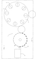
figure 1 illustrates an apparatus for producing sterile receptacles, according to the claimed method, in a schematic plan view; -
figure 2 illustrates a detail of the transferring unit of the producing apparatus offigure 1 , in a lateral view; -
figure 3 schematically illustrates a parison, in a lateral view; -
figure 4 illustrates a variant of the producing apparatus offigure 1 . With reference to the figures, the number 1 indicates an apparatus for producing sterile receptacles starting fromparisons 4 made of thermoplastic material. - Preferably, each
parison 4 has atubular body 4a and aneck 4b (usually threaded) not subject to processing. -
Figure 3 schematically illustrates the structure of aparison 4, in which an annular protrusion of theneck 4b, indicated byreference 4c, is also visible. Thisannular protrusion 4c is known in the art as a "bague". - The producing apparatus 1 comprises:
- a
moulding unit 13 for mouldingparisons 4 starting from granules of thermoplastic material (e.g. PET); - a forming
unit 3 for forming themoulded parisons 4, in particular by stretch-blowing. - A transferring
unit 23 is interposed between themoulding unit 13 and the formingunit 3, which comprises at least onethermal conditioning device 230 configured to heat thetubular portion 4a of theparisons 4 in such a way that theparisons 4 leaving the transferringunit 23 have a thermal profile adapted to allow forming by stretch-blowing in the formingunit 3. - In fact, the
parisons 4 leave themoulding unit 13 with thetubular body 4a at a temperature above 100°C. - The
neck 4b is instead cooled so as to have a temperature lower than the glass temperature of the PET, preferably between 20°C and 40°C. - This creates a temperature imbalance between the
neck 4b and thetubular body 4a, which imbalance generates an uncontrolled thermal profile which extends down to below thebague 4c. This situation is not suitable for forming theparison 4. - Thanks to the passage in the transferring
unit 23 provided with thethermal conditioning device 230, theparisons 4 re-establish an optimal thermal profile adapted to allow forming by stretch-blowing. -
Sterilization devices 231 of theparisons 4 are located on the transferringunit 23 which are configured to sterilize theparisons 4 at least internally, i.e., the walls inside the tubular cavity. - Advantageously, therefore, both the thermal conditioning of the
parisons 4 and their sterilization occur in the transferringunit 23. - In accordance with the embodiment described and illustrated herein, the transferring
unit 23 is of the rotary carousel type. - In the embodiment described and illustrated herein, the transferring
unit 23 comprises a star-wheel having a plurality of supporting stations for supporting theparisons 4 by theneck 4b thereof. - Preferably, each supporting station comprises a
pocket 25 at the external circumference of the star-wheel for receiving and supporting theneck 4b of one of theparisons 4. - As an alternative to the pocket, in each supporting station gripping means 26 (e.g., grippers) of the
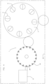
neck 4b of theparison 4 is present. This variant is illustrated infigure 4 . - According to the invention, a
thermal conditioning device 230 is arranged at each supporting station. - In accordance with the embodiment described and illustrated herein, each
thermal conditioning device 230 is a heating element, such as a thermal resistance, installed in thecorresponding pocket 25. - In particular, the
thermal conditioning device 230 is arranged in such a way as to contact a lower portion of thebague 4c of theparison 4 present in thepocket 25, as seen infigure 2 . - The
thermal conditioning device 230 may be configured at least in one activated condition in which it heats a zone of thetubular body 4a beneath thebague 4c of theparison 4. - In one embodiment, the
thermal conditioning device 230 is an infrared or microwave type generator, preferably mounted on the star-wheel of the transferringunit 23. - One of the
sterilization devices 231 is also located at each supporting station (hence thepocket 25 or the gripping means 26). - For example, each
sterilization device 231 consists of a spray nozzle of a sterilizing fluid. - In one embodiment not according to the invention the transferring
unit 23 is of the linear type. - The
moulding unit 13 and the formingunit 3 are synchronized so that eachmoulded parison 4 is transferred directly to the formingunit 3 via the transferringunit 23. - Preferably, the
moulding unit 13 of theparisons 4 comprises a plurality of moulding stations, in each of which a mould is arranged constituted by a concave portion (also called the "female mould") and a convex portion (also called the "male mould") which is insertable in the concave portion. Preferably, themoulding unit 13 is a conventional type, alternating cycle machine with injection-type moulds. Alternatively, themoulding unit 13 is a continuously operating rotary machine with compression or injection-compression type moulds. - In accordance with one embodiment, the
moulding unit 13 comprises means for cleaning the surfaces of the moulds adapted to come into contact with theparisons 4. - According to the invention, the
moulding unit 13 is arranged in anultra-clean environment 24. In this context, ultra-clean environment is intended as a volume which is separated from the (dirty) external environment by means of a physical separation which has the purpose of limiting the entrance of contaminants from the external environment. - In particular, the physical separation need not necessarily be tight sealed. According to the invention, the
ultra-clean environment 24 is maintained at an overpressure value of about 10 Pa. Preferably, microfiltered air flows from special devices (HEPA filters, e.g., level H13) used to generate such overpressure. The purpose of theultra-clean environment 24 is to limit the contamination of theparisons 4. - According to the invention, the
thermal conditioning unit 23 and the formingunit 3 are also located in theultra-clean environment 24. - Preferably, the forming
unit 3 is of the rotary carousel type. In an alternative embodiment (not shown), the formingunit 3 is of the linear type. - The forming
unit 3 comprises a plurality of formingstations 5 in each of which a mould of a known type is arranged. - The proposed disclosure further relates to a bottling plant not according to the invention comprising:
- the producing apparatus 1 for producing sterile receptacles described above;
- a filling apparatus for filling the formed receptacles, arranged downstream of the producing apparatus 1;
- a closing apparatus for closing the filled receptacles, which is arranged downstream of the filling apparatus.
- The method for producing sterile receptacles, in accordance with the present invention, is described below.
- First of all, a step is provided for moulding the
parisons 4 starting from granules of thermoplastic material. - Preferably, the surfaces of the moulds adapted to come into contact with the
parisons 4 are cleaned before starting the moulding. - Subsequently, the granules are melted and moulded in the moulds by injection or compression or injection-compression moulding.
- At the end of the moulding step the
parisons 4 have a temperature around 100°C. Theneck 4b of theparisons 4 is cooled to allow it to be gripped. Themoulded parisons 4 are then subjected to a thermal conditioning step to give theparisons 4 a predefined thermal profile adapted to allow the forming by stretch-blowing. - The
moulded parisons 4 are also subjected to a sterilization step. - Originally, the sterilization step overlaps at least partly with the thermal conditioning step.
- In accordance with a variant of the method, the sterilization step of the
parisons 4 and the thermal conditioning step are simultaneous, i.e., completely overlapping. - At the end of the sterilization/thermal conditioning step, the
parisons 4 are introduced into the moulds of the formingunit 3 and the receptacles are formed by stretch-blowing. - Leaving the forming
unit 3, the receptacles are transferred to the filling apparatus. - In particular, the
neck 4b of the receptacles (which has not undergone processing) is maintained in sterile conditions thanks to the presence of a first isolation device, which in fact isolates the volume in which the filling occurs - volume having an extension such as to comprise theneck 4b of the receptacles and the filling nozzles but not the body of the formed receptacles. - Once filled, the receptacles are sent to the closing or capping apparatus. The characteristics of the method for producing sterile receptacles according to the present invention emerge clearly from the above description, as do the advantages.
- First of all, having integrated the parison moulding unit within the receptacle producing apparatus, together with the fact that the sterilization step of the parisons is at least overlapping the thermal conditioning step before the forming by stretch-blowing, allows reducing the structural complexity of the "aseptic" blowing machine with isolator and of all the parts operating at the interface thereof (e.g., sealing systems between the sterile zone and the external environment, separation of the stretching rod, sterilization system of the blowing air circuit, etc.).
- In fact, the integration of the moulding unit allows to keep the contamination of the parisons under control during their generation and to deliver parisons to the blowing machine with a low level of contamination.
- This is also due to the high temperature of the parisons leaving the moulding unit, which is about 100°C.
- The handling of the parisons only by means of gripping shells operating on the neck thereof and the maintenance of the parisons in an ultra-clean environment also contributes to this end.
- Furthermore, having disconnected the sterilization from the blowing machine facilitates maintenance and, in particular, the repair of failures related to the sterilization devices.
Claims (2)
- Method for producing sterile receptacles, comprising the steps of:- obtaining parisons (4) by melting and moulding granules of thermoplastic material in a moulding unit (13) for moulding parisons (4), each of said parisons (4) having a tubular body (4a) and a neck (4b) with an annular protrusion called bague (4c), the parisons (4) leaving the moulding unit (13) with the tubular body (4a) at a temperature above 100°C and the neck (4b) being cooled so as to have a temperature between 20°C and 40°C, this creating a temperature imbalance between the neck (4b) and the tubular body (4a), which temperature imbalance generates an uncontrolled thermal profile which extends down below the bague (4c);- sterilizing the moulded parisons (4);- submitting the moulded parisons (4) to thermal conditioning in a transferring unit (23) comprising a star-wheel having a plurality of supporting stations for supporting the parisons (4) by their neck (4b), in each supporting station being arranged one thermal conditioning device (230) configured to heat a tubular body (4a) of said parisons (4) so that said parisons (4) leaving the transferring unit (23) have a predefined thermal profile adapted to allow forming by stretch-blowing;- obtaining the receptacles by stretch-blowing said parisons (4) in a forming unit (3) for stretch-blowing the parisons (4), said transferring unit (23) being interposed between said moulding unit (13) and said forming unit (3),said moulding unit (13), said forming unit (3) and said transferring unit (23) being arranged in an ultra-clean environment (24), i.e. in a volume that is separated from the external environment by means of a physical separation that has the purpose of limiting the entrance of contaminants from the external environment, said ultra-clean environment (24) being maintained at an overpressure value of about 10 Pa, microfiltered air flows coming from HEPA filters of level H13 being used to generate such overpressure,
the step of sterilizing the moulded parisons (4) occurring at least partly during the step of thermal conditioning of the parisons (4) in a plurality of sterilization devices (231) configured to sterilize at least internally said parisons (4), said sterilization devices (231) being installed on said transferring unit (23), one of the sterilization devices (231) being located at each supporting station. - Method according to claim 1, wherein the step of sterilizing the parisons (4) and the step of thermal conditioning of the parisons (4) are simultaneous.
Applications Claiming Priority (1)
| Application Number | Priority Date | Filing Date | Title |
|---|---|---|---|
| IT102019000013053A IT201900013053A1 (en) | 2019-07-26 | 2019-07-26 | METHOD AND APPARATUS FOR PRODUCTION OF STERILE CONTAINERS AND BOTTLING PLANT INCLUDING THIS APPARATUS |
Publications (2)
| Publication Number | Publication Date |
|---|---|
| EP3769793A1 EP3769793A1 (en) | 2021-01-27 |
| EP3769793B1 true EP3769793B1 (en) | 2023-09-06 |
Family
ID=68733519
Family Applications (1)
| Application Number | Title | Priority Date | Filing Date |
|---|---|---|---|
| EP20185560.8A Active EP3769793B1 (en) | 2019-07-26 | 2020-07-13 | Method for producing sterile receptacles and bottling plant comprising said producing apparatus |
Country Status (3)
| Country | Link |
|---|---|
| EP (1) | EP3769793B1 (en) |
| HU (1) | HUE063706T2 (en) |
| IT (1) | IT201900013053A1 (en) |
Family Cites Families (8)
| Publication number | Priority date | Publication date | Assignee | Title |
|---|---|---|---|---|
| JPH08164925A (en) | 1994-12-12 | 1996-06-25 | Coca Cola Co:The | Beverage packaging device |
| FR2887526B1 (en) * | 2005-06-24 | 2007-09-07 | Sidel Sas | PROCESS FOR STERILIZING PREFORMS AND SYSTEM PRODUCING STERILE BOTTLES THEREFROM |
| CN102196889B (en) | 2008-08-28 | 2014-10-15 | 东洋制罐株式会社 | Compression-molding mold of preform and preform, and aseptic filling system for food or drink and method for producing blow-molded container using the same |
| DE102008056346A1 (en) * | 2008-11-07 | 2010-05-12 | Krones Ag | Process for the pretreatment of preforms and stretch blow molding machine for the pretreatment and stretch blow molding of preforms into containers |
| DE102008057403A1 (en) | 2008-11-14 | 2010-05-20 | Krones Ag | Apparatus and method for producing plastic containers |
| EP2578504A4 (en) | 2010-05-25 | 2015-05-27 | Otsuka Pharma Co Ltd | Aseptic filling system |
| DE102010034895A1 (en) * | 2010-08-19 | 2012-02-23 | Krones Aktiengesellschaft | Device for treating packaging |
| EP3227085B1 (en) | 2014-12-01 | 2018-10-31 | Gea Procomac S.p.A. | A production apparatus of sterile receptacles, a bottling plant comprising the apparatus and a production method of a sterile receptacle |
-
2019
- 2019-07-26 IT IT102019000013053A patent/IT201900013053A1/en unknown
-
2020
- 2020-07-13 EP EP20185560.8A patent/EP3769793B1/en active Active
- 2020-07-13 HU HUE20185560A patent/HUE063706T2/en unknown
Also Published As
| Publication number | Publication date |
|---|---|
| EP3769793A1 (en) | 2021-01-27 |
| IT201900013053A1 (en) | 2021-01-26 |
| HUE063706T2 (en) | 2024-01-28 |
Similar Documents
| Publication | Publication Date | Title |
|---|---|---|
| US8770957B2 (en) | Blow moulding machine, method of exchanging blow moulding station components and beverage filling plant and/or beverage container production plant | |
| US9505162B2 (en) | Apparatus for shaping plastic preforms, comprising a sterile chamber | |
| WO2010024165A1 (en) | Compression-molding mold of preform and preform, and aseptic filling system for food or drink and method for producing blow-molded container using the same | |
| JPH08164925A (en) | Beverage packaging device | |
| US10343325B2 (en) | Production apparatus of sterile receptacles, a bottling plant comprising the apparatus and a production method of a sterile receptacle | |
| JP5382298B2 (en) | Aseptic filling system for container-packed drinks and foodstuffs | |
| CN107922074B (en) | Aseptic filling system, container sterilization unit, and aseptic filling method | |
| US10800088B2 (en) | Process station for a parison or a container made of thermoplastic material, apparatus for processing parisons or containers, production and packaging line for producing and packaging the containers and method for producing and packaging containers | |
| EP3769793B1 (en) | Method for producing sterile receptacles and bottling plant comprising said producing apparatus | |
| JP2017095114A (en) | Aseptic filling device and decontamination method thereof | |
| JP2004001840A (en) | Beverage filling apparatus | |
| EP3240753B1 (en) | Apparatus for filling containers | |
| JP2019064682A (en) | Sterilization method of aseptic filling machine | |
| JP2022093895A (en) | Aseptic filling method and aseptic filling machine | |
| EP3172028B1 (en) | Method for moulding and sterilizing a container made of plastic material, device for moulding and sterilizing a container made of plastic material and moulding and sterilizing machine | |
| JP5880647B2 (en) | Aseptic filling method and apparatus | |
| JP6079734B2 (en) | Aseptic filling method and apparatus | |
| JP5804165B2 (en) | Aseptic filling equipment | |
| JP5804164B2 (en) | Aseptic filling method and apparatus | |
| JP7472889B2 (en) | Aseptic filling method and aseptic filling machine | |
| WO2023176425A1 (en) | Blow molding system, content filling system, blow molding method, and content filling method | |
| WO2021100557A1 (en) | Aseptic filling method and aseptic filling machine | |
| JP2017095115A (en) | Aseptic filling device and decontamination method thereof | |
| JP6516098B2 (en) | Content filling method and apparatus | |
| JP6007954B2 (en) | Aseptic filling method and apparatus |
Legal Events
| Date | Code | Title | Description |
|---|---|---|---|
| PUAI | Public reference made under article 153(3) epc to a published international application that has entered the european phase |
Free format text: ORIGINAL CODE: 0009012 |
|
| STAA | Information on the status of an ep patent application or granted ep patent |
Free format text: STATUS: THE APPLICATION HAS BEEN PUBLISHED |
|
| AK | Designated contracting states |
Kind code of ref document: A1 Designated state(s): AL AT BE BG CH CY CZ DE DK EE ES FI FR GB GR HR HU IE IS IT LI LT LU LV MC MK MT NL NO PL PT RO RS SE SI SK SM TR |
|
| AX | Request for extension of the european patent |
Extension state: BA ME |
|
| STAA | Information on the status of an ep patent application or granted ep patent |
Free format text: STATUS: REQUEST FOR EXAMINATION WAS MADE |
|
| 17P | Request for examination filed |
Effective date: 20210422 |
|
| RBV | Designated contracting states (corrected) |
Designated state(s): AL AT BE BG CH CY CZ DE DK EE ES FI FR GB GR HR HU IE IS IT LI LT LU LV MC MK MT NL NO PL PT RO RS SE SI SK SM TR |
|
| STAA | Information on the status of an ep patent application or granted ep patent |
Free format text: STATUS: EXAMINATION IS IN PROGRESS |
|
| 17Q | First examination report despatched |
Effective date: 20211001 |
|
| GRAP | Despatch of communication of intention to grant a patent |
Free format text: ORIGINAL CODE: EPIDOSNIGR1 |
|
| STAA | Information on the status of an ep patent application or granted ep patent |
Free format text: STATUS: GRANT OF PATENT IS INTENDED |
|
| GRAS | Grant fee paid |
Free format text: ORIGINAL CODE: EPIDOSNIGR3 |
|
| INTG | Intention to grant announced |
Effective date: 20230523 |
|
| P01 | Opt-out of the competence of the unified patent court (upc) registered |
Effective date: 20230526 |
|
| GRAA | (expected) grant |
Free format text: ORIGINAL CODE: 0009210 |
|
| STAA | Information on the status of an ep patent application or granted ep patent |
Free format text: STATUS: THE PATENT HAS BEEN GRANTED |
|
| AK | Designated contracting states |
Kind code of ref document: B1 Designated state(s): AL AT BE BG CH CY CZ DE DK EE ES FI FR GB GR HR HU IE IS IT LI LT LU LV MC MK MT NL NO PL PT RO RS SE SI SK SM TR |
|
| REG | Reference to a national code |
Ref country code: GB Ref legal event code: FG4D |
|
| REG | Reference to a national code |
Ref country code: CH Ref legal event code: EP |
|
| REG | Reference to a national code |
Ref country code: DE Ref legal event code: R096 Ref document number: 602020017077 Country of ref document: DE |
|
| REG | Reference to a national code |
Ref country code: IE Ref legal event code: FG4D |
|
| REG | Reference to a national code |
Ref country code: LT Ref legal event code: MG9D |
|
| REG | Reference to a national code |
Ref country code: NL Ref legal event code: MP Effective date: 20230906 |
|
| PG25 | Lapsed in a contracting state [announced via postgrant information from national office to epo] |
Ref country code: GR Free format text: LAPSE BECAUSE OF FAILURE TO SUBMIT A TRANSLATION OF THE DESCRIPTION OR TO PAY THE FEE WITHIN THE PRESCRIBED TIME-LIMIT Effective date: 20231207 |
|
| REG | Reference to a national code |
Ref country code: HU Ref legal event code: AG4A Ref document number: E063706 Country of ref document: HU |
|
| PG25 | Lapsed in a contracting state [announced via postgrant information from national office to epo] |
Ref country code: SE Free format text: LAPSE BECAUSE OF FAILURE TO SUBMIT A TRANSLATION OF THE DESCRIPTION OR TO PAY THE FEE WITHIN THE PRESCRIBED TIME-LIMIT Effective date: 20230906 Ref country code: RS Free format text: LAPSE BECAUSE OF FAILURE TO SUBMIT A TRANSLATION OF THE DESCRIPTION OR TO PAY THE FEE WITHIN THE PRESCRIBED TIME-LIMIT Effective date: 20230906 Ref country code: NO Free format text: LAPSE BECAUSE OF FAILURE TO SUBMIT A TRANSLATION OF THE DESCRIPTION OR TO PAY THE FEE WITHIN THE PRESCRIBED TIME-LIMIT Effective date: 20231206 Ref country code: LV Free format text: LAPSE BECAUSE OF FAILURE TO SUBMIT A TRANSLATION OF THE DESCRIPTION OR TO PAY THE FEE WITHIN THE PRESCRIBED TIME-LIMIT Effective date: 20230906 Ref country code: LT Free format text: LAPSE BECAUSE OF FAILURE TO SUBMIT A TRANSLATION OF THE DESCRIPTION OR TO PAY THE FEE WITHIN THE PRESCRIBED TIME-LIMIT Effective date: 20230906 Ref country code: HR Free format text: LAPSE BECAUSE OF FAILURE TO SUBMIT A TRANSLATION OF THE DESCRIPTION OR TO PAY THE FEE WITHIN THE PRESCRIBED TIME-LIMIT Effective date: 20230906 Ref country code: GR Free format text: LAPSE BECAUSE OF FAILURE TO SUBMIT A TRANSLATION OF THE DESCRIPTION OR TO PAY THE FEE WITHIN THE PRESCRIBED TIME-LIMIT Effective date: 20231207 Ref country code: FI Free format text: LAPSE BECAUSE OF FAILURE TO SUBMIT A TRANSLATION OF THE DESCRIPTION OR TO PAY THE FEE WITHIN THE PRESCRIBED TIME-LIMIT Effective date: 20230906 |
|
| REG | Reference to a national code |
Ref country code: AT Ref legal event code: UEP Ref document number: 1607649 Country of ref document: AT Kind code of ref document: T Effective date: 20230906 |
|
| PG25 | Lapsed in a contracting state [announced via postgrant information from national office to epo] |
Ref country code: NL Free format text: LAPSE BECAUSE OF FAILURE TO SUBMIT A TRANSLATION OF THE DESCRIPTION OR TO PAY THE FEE WITHIN THE PRESCRIBED TIME-LIMIT Effective date: 20230906 |
|
| PG25 | Lapsed in a contracting state [announced via postgrant information from national office to epo] |
Ref country code: IS Free format text: LAPSE BECAUSE OF FAILURE TO SUBMIT A TRANSLATION OF THE DESCRIPTION OR TO PAY THE FEE WITHIN THE PRESCRIBED TIME-LIMIT Effective date: 20240106 |