EP3769710B1 - Myokardgewebeablation mit enger temperaturvariation - Google Patents
Myokardgewebeablation mit enger temperaturvariation Download PDFInfo
- Publication number
- EP3769710B1 EP3769710B1 EP20187664.6A EP20187664A EP3769710B1 EP 3769710 B1 EP3769710 B1 EP 3769710B1 EP 20187664 A EP20187664 A EP 20187664A EP 3769710 B1 EP3769710 B1 EP 3769710B1
- Authority
- EP
- European Patent Office
- Prior art keywords
- ablation
- temperature
- distal end
- energy
- pumping rate
- Prior art date
- Legal status (The legal status is an assumption and is not a legal conclusion. Google has not performed a legal analysis and makes no representation as to the accuracy of the status listed.)
- Active
Links
Images
Classifications
-
- A—HUMAN NECESSITIES
- A61—MEDICAL OR VETERINARY SCIENCE; HYGIENE
- A61B—DIAGNOSIS; SURGERY; IDENTIFICATION
- A61B18/00—Surgical instruments, devices or methods for transferring non-mechanical forms of energy to or from the body
- A61B18/04—Surgical instruments, devices or methods for transferring non-mechanical forms of energy to or from the body by heating
- A61B18/12—Surgical instruments, devices or methods for transferring non-mechanical forms of energy to or from the body by heating by passing a current through the tissue to be heated, e.g. high-frequency current
- A61B18/14—Probes or electrodes therefor
- A61B18/1492—Probes or electrodes therefor having a flexible, catheter-like structure, e.g. for heart ablation
-
- A—HUMAN NECESSITIES
- A61—MEDICAL OR VETERINARY SCIENCE; HYGIENE
- A61B—DIAGNOSIS; SURGERY; IDENTIFICATION
- A61B18/00—Surgical instruments, devices or methods for transferring non-mechanical forms of energy to or from the body
- A61B18/04—Surgical instruments, devices or methods for transferring non-mechanical forms of energy to or from the body by heating
- A61B18/12—Surgical instruments, devices or methods for transferring non-mechanical forms of energy to or from the body by heating by passing a current through the tissue to be heated, e.g. high-frequency current
- A61B18/1206—Generators therefor
-
- A—HUMAN NECESSITIES
- A61—MEDICAL OR VETERINARY SCIENCE; HYGIENE
- A61N—ELECTROTHERAPY; MAGNETOTHERAPY; RADIATION THERAPY; ULTRASOUND THERAPY
- A61N7/00—Ultrasound therapy
- A61N7/02—Localised ultrasound hyperthermia
- A61N7/022—Localised ultrasound hyperthermia intracavitary
-
- A—HUMAN NECESSITIES
- A61—MEDICAL OR VETERINARY SCIENCE; HYGIENE
- A61B—DIAGNOSIS; SURGERY; IDENTIFICATION
- A61B17/00—Surgical instruments, devices or methods
- A61B17/00234—Surgical instruments, devices or methods for minimally invasive surgery
- A61B2017/00238—Type of minimally invasive operation
- A61B2017/00243—Type of minimally invasive operation cardiac
-
- A—HUMAN NECESSITIES
- A61—MEDICAL OR VETERINARY SCIENCE; HYGIENE
- A61B—DIAGNOSIS; SURGERY; IDENTIFICATION
- A61B18/00—Surgical instruments, devices or methods for transferring non-mechanical forms of energy to or from the body
- A61B2018/00315—Surgical instruments, devices or methods for transferring non-mechanical forms of energy to or from the body for treatment of particular body parts
- A61B2018/00345—Vascular system
- A61B2018/00351—Heart
- A61B2018/00357—Endocardium
-
- A—HUMAN NECESSITIES
- A61—MEDICAL OR VETERINARY SCIENCE; HYGIENE
- A61B—DIAGNOSIS; SURGERY; IDENTIFICATION
- A61B18/00—Surgical instruments, devices or methods for transferring non-mechanical forms of energy to or from the body
- A61B2018/00571—Surgical instruments, devices or methods for transferring non-mechanical forms of energy to or from the body for achieving a particular surgical effect
- A61B2018/00577—Ablation
-
- A—HUMAN NECESSITIES
- A61—MEDICAL OR VETERINARY SCIENCE; HYGIENE
- A61B—DIAGNOSIS; SURGERY; IDENTIFICATION
- A61B18/00—Surgical instruments, devices or methods for transferring non-mechanical forms of energy to or from the body
- A61B2018/00571—Surgical instruments, devices or methods for transferring non-mechanical forms of energy to or from the body for achieving a particular surgical effect
- A61B2018/00613—Irreversible electroporation
-
- A—HUMAN NECESSITIES
- A61—MEDICAL OR VETERINARY SCIENCE; HYGIENE
- A61B—DIAGNOSIS; SURGERY; IDENTIFICATION
- A61B18/00—Surgical instruments, devices or methods for transferring non-mechanical forms of energy to or from the body
- A61B2018/00636—Sensing and controlling the application of energy
- A61B2018/00642—Sensing and controlling the application of energy with feedback, i.e. closed loop control
-
- A—HUMAN NECESSITIES
- A61—MEDICAL OR VETERINARY SCIENCE; HYGIENE
- A61B—DIAGNOSIS; SURGERY; IDENTIFICATION
- A61B18/00—Surgical instruments, devices or methods for transferring non-mechanical forms of energy to or from the body
- A61B2018/00636—Sensing and controlling the application of energy
- A61B2018/00696—Controlled or regulated parameters
- A61B2018/00702—Power or energy
-
- A—HUMAN NECESSITIES
- A61—MEDICAL OR VETERINARY SCIENCE; HYGIENE
- A61B—DIAGNOSIS; SURGERY; IDENTIFICATION
- A61B18/00—Surgical instruments, devices or methods for transferring non-mechanical forms of energy to or from the body
- A61B2018/00636—Sensing and controlling the application of energy
- A61B2018/00696—Controlled or regulated parameters
- A61B2018/00714—Temperature
-
- A—HUMAN NECESSITIES
- A61—MEDICAL OR VETERINARY SCIENCE; HYGIENE
- A61B—DIAGNOSIS; SURGERY; IDENTIFICATION
- A61B18/00—Surgical instruments, devices or methods for transferring non-mechanical forms of energy to or from the body
- A61B2018/00636—Sensing and controlling the application of energy
- A61B2018/00696—Controlled or regulated parameters
- A61B2018/00744—Fluid flow
-
- A—HUMAN NECESSITIES
- A61—MEDICAL OR VETERINARY SCIENCE; HYGIENE
- A61B—DIAGNOSIS; SURGERY; IDENTIFICATION
- A61B18/00—Surgical instruments, devices or methods for transferring non-mechanical forms of energy to or from the body
- A61B2018/00636—Sensing and controlling the application of energy
- A61B2018/00773—Sensed parameters
- A61B2018/00791—Temperature
- A61B2018/00797—Temperature measured by multiple temperature sensors
-
- A—HUMAN NECESSITIES
- A61—MEDICAL OR VETERINARY SCIENCE; HYGIENE
- A61B—DIAGNOSIS; SURGERY; IDENTIFICATION
- A61B18/00—Surgical instruments, devices or methods for transferring non-mechanical forms of energy to or from the body
- A61B2018/00636—Sensing and controlling the application of energy
- A61B2018/00773—Sensed parameters
- A61B2018/00791—Temperature
- A61B2018/00821—Temperature measured by a thermocouple
-
- A—HUMAN NECESSITIES
- A61—MEDICAL OR VETERINARY SCIENCE; HYGIENE
- A61B—DIAGNOSIS; SURGERY; IDENTIFICATION
- A61B18/00—Surgical instruments, devices or methods for transferring non-mechanical forms of energy to or from the body
- A61B2018/00636—Sensing and controlling the application of energy
- A61B2018/00773—Sensed parameters
- A61B2018/00839—Bioelectrical parameters, e.g. ECG, EEG
-
- A—HUMAN NECESSITIES
- A61—MEDICAL OR VETERINARY SCIENCE; HYGIENE
- A61B—DIAGNOSIS; SURGERY; IDENTIFICATION
- A61B2218/00—Details of surgical instruments, devices or methods for transferring non-mechanical forms of energy to or from the body
- A61B2218/001—Details of surgical instruments, devices or methods for transferring non-mechanical forms of energy to or from the body having means for irrigation and/or aspiration of substances to and/or from the surgical site
- A61B2218/002—Irrigation
Definitions
- the present invention relates generally to cardiac ablation, and specifically to controlling the temperature of myocardial tissue during an ablation procedure.
- a temperature sensor may be positioned within a distal tip of the catheter, and the region being ablated may be irrigated with an irrigation fluid, typically saline, in order to prevent charring.
- U.S. Patent 5,868,743 to Saul, et al. describes a method of targeting and ablating cardiac tissue.
- the method describes modulating the delivered ablation power between 0.5 - 5.0 W using feedback from a catheter-embedded thermocouple in order to attempt to achieve a selected target temperature of between 45°C - 95°C.
- the method also describes a mode of operation that achieves a tissue temperature below 52°C, and preferably in the range of 48°C - 52°C.
- U.S. Patent 5,735,846 to Panescu, et al. describes systems and methods for ablating body tissue using an electrode for contacting tissue at a tissue-electrode interface to transmit ablation energy at a determinable power level.
- the method includes applying 30W of radiofrequency catheter ablation power in order to achieve ablation temperatures between 45°C - 50°C.
- U.S. Patent 5,743,903 to Stern, et al. describes a cardiac ablation system and method that uses an ablation electrode having an energy emitting body.
- the system can maintain the temperature of the tissue undergoing ablation can also above a prescribed minimum temperature condition (e.g. 40°C).
- U.S. Patent 6,063,078 to Wittkampf describes methods and systems for ablating tissue within a body.
- the system includes a control that can be aimed so that a constant power to the electrode is maintained, or a constant temperature of the tip electrode is maintained.
- US 2017/312008A1 presents ablation systems and methods directed toward delivering pulsed radiofrequency (RF) energy to target tissue.
- RF radiofrequency
- EP 3375396A1 discloses an apparatus, consisting of a probe configured to be inserted into contact with a myocardium, and an electrode attached to the probe.
- a temperature sensor incorporated in the probe, is configured to output a temperature signal.
- a pump irrigates the myocardium, via the probe, with an irrigation fluid at a controllable rate, and a radiofrequency (RF) signal generator applies RF power via the electrode to the myocardium, so as to ablate the myocardium.
- RF radiofrequency
- the apparatus also has processing circuitry that measures a temperature of the probe, based on the temperature signal, while the RF power is applied and, when the measured temperature exceeds a preset target temperature, iteratively reduces the RF power applied by the signal generator and concurrently iteratively varies a rate of irrigation of the irrigation fluid provided by the pump, until the measured temperature is reduced to the preset target temperature.
- an irrigated ablation system including a medical probe including a flexible insertion tube having a distal end configured to be inserted into a chamber of a heart, an ablation electrode disposed at the distal end and configured to convey ablation energy to a region of myocardial tissue with which the electrode is in contact, a temperature sensor disposed at the distal end and configured to output a temperature signal indicative of a temperature of the region of myocardial tissue, a channel contained within the insertion tube and configured to deliver an irrigation fluid to the distal end, and one or more fluid ports coupled to the channel and disposed at the distal end.
- the irrigated ablation system also includes an ablation energy generator configured to apply a specified level of the ablation energy to the ablation electrode, a pump configured to force the irrigation fluid into the channel at a controllable pumping rate, and a processor configured to control the pumping rate responsively to the temperature signal so that a difference between a specified ablation temperature, which is no greater than 55°C, and the indicated temperature is no greater than ⁇ 2.5°C while the ablation energy generator delivers a constant level of the ablation energy to the ablation electrode.
- an ablation energy generator configured to apply a specified level of the ablation energy to the ablation electrode
- a pump configured to force the irrigation fluid into the channel at a controllable pumping rate
- a processor configured to control the pumping rate responsively to the temperature signal so that a difference between a specified ablation temperature, which is no greater than 55°C, and the indicated temperature is no greater than ⁇ 2.5°C while the ablation energy generator delivers a constant level of the ablation energy to the ablation electrode.
- the medical probe includes an intracardiac catheter.
- the irrigation fluid includes a saline solution.
- the specified ablation temperature is at least 42°C.
- the temperature sensor includes a thermocouple.
- the irrigated ablation system may also include a temperature module configured to receive the temperature signal from the temperature sensor, to compute, based on the temperature signal, a temperature value, and wherein the processor is configured to control the pumping rate responsively to the temperature signal by controlling the pumping rate responsively to the temperature value.
- the processor is configured to control the pumping rate responsively to the temperature signal by applying a proportional-integral-derivative controller (PID) algorithm to the indicated temperature.
- PID proportional-integral-derivative controller
- the ablation energy can be selected from a list consisting of radio-frequency (RF) energy, high-intensity focused ultrasound (HIFU) energy and pulsed field ablation (PFA) energy.
- RF radio-frequency
- HIFU high-intensity focused ultrasound
- PFA pulsed field ablation
- an unclaimed method including applying a specified level of ablation energy to an ablation electrode disposed at a distal end of a medical probe inserted into a chamber of a heart and in contact with a region of myocardial tissue, receiving, by a processor from a temperature sensor disposed at the distal end, a signal indicative of a temperature of the region of myocardial tissue, and controlling a pumping rate of irrigation fluid to one or more fluid ports disposed at the distal end distal end responsively to the temperature signal so that a difference between a specified ablation temperature, which is no greater than 55° C, and the indicated temperature is no greater than ⁇ 2.5° C while delivering a constant level of the ablation energy to the ablation electrode.
- a computer software product operated in conjunction with an intracardiac catheter having a distal end inserted into a chamber of a heart, a channel contained within the insertion tube and configured to deliver an irrigation fluid to the distal end, and one or more fluid ports coupled to the channel and disposed at the distal end
- the product including a non-transitory computer-readable medium, in which program instructions are stored, which instructions, when read by a computer, cause the computer to apply a specified level of ablation energy to an ablation electrode disposed at the distal end and configured to convey ablation energy to a region of myocardial tissue with which the electrode is in contact to receive, from a temperature sensor disposed at the distal end, a temperature signal indicative of a temperature of the region of myocardial tissue, and to control a pumping rate of irrigation fluid to the one or more fluid ports end responsively to the temperature signal so that a difference between a specified ablation temperature, which is no greater than 55° C, and the indicated temperature is
- Embodiments of the present disclosure describe systems and unclaimed methods for maintaining the temperature of myocardial tissue within a specified range during an ablation procedure.
- the system comprises a medical probe, an ablation energy generator, a pump, and a processor.
- the medical probe comprises a flexible insertion tube having a distal end configured to be inserted into a chamber of a heart, and an electrode disposed at the distal end and configured to convey ablation energy to a region of myocardial tissue with which the electrode is in contact.
- the medical probe also comprises a temperature sensor disposed at the distal end and configured to output a temperature signal indicative of a temperature of the region of myocardial tissue.
- the medical probe further comprises a channel contained within the insertion tube and configured to deliver an irrigation fluid to the distal end.
- the medical probe additionally includes one or more fluid ports coupled to the channel and disposed at the distal end.
- the ablation energy generator is configured to apply a specified level of the ablation energy to the ablation electrode
- the pump is configured to force the irrigation fluid into the channel at a controllable pumping rate.
- the processor is configured to control the pumping rate responsively to the temperature signal so that a difference between a specified ablation temperature, which is typically no greater than 55°C, and an indicated or target temperature, is no greater than ⁇ 2.5°C while the ablation signal generator delivers a constant level of the ablation energy to the ablation electrode.
- systems implementing exemplary embodiments of the invention can help reduce the risk of heat-based complications (e.g., steam-pops) during ablation procedures.
- heat-based complications e.g., steam-pops
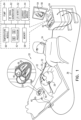
- FIG 1 is a schematic, pictorial illustration of a medical system 20 comprising a medical probe 22 and a control console 24.
- Medical system 20 may be based, for example, on the CARTO ® system, produced by Biosense Webster Inc. (Diamond Bar, California, U.S.A.).
- medical probe 22 comprises an intracardiac catheter that can be used for diagnostic or therapeutic treatment, such as for ablating tissue in a heart 26 of a patient 28. Medical probe 22 may also be referred to as an ablation catheter.
- Medical probe 22 comprises an insertion tube 30 and a handle 32 coupled to a proximal end of the insertion tube.
- a medical professional 34 can insert a distal end 36 of medical probe 22 into a body cavity in patient 28.
- medical professional 34 can insert medical probe 22 through the vascular system of patient 28 so that distal end 36 enters a chamber of heart 26 and engages myocardial tissue at a desired location or locations.
- Control console 24 is connected, by a cable 38 to body surface electrodes, which typically comprise adhesive skin patches 40 that are affixed to patient 28.
- Control console 24 comprises a processor 42 that, in conjunction with a current tracking module 44, determines position coordinates of distal end 36 inside heart 26 based on impedances measured between adhesive skin patches 40 and a location electrode 46 that is disposed at distal end 36, as described in the description referencing Figure 2 hereinbelow.
- Location electrode 46 is connected to control console 24 by wires (not shown) running through medical probe 22.
- Processor 42 may comprise real-time noise reduction circuitry 48 typically configured as a field programmable gate array (FPGA), followed by an analog-to-digital (A/D) ECG (electrocardiograph) signal conversion integrated circuit 50.
- the processor can pass the signal from A/D ECG circuit 50 to another processor and/or can be programmed to perform one or more algorithms disclosed herein, each of the one or more algorithms comprising steps described hereinbelow.
- the processor uses noise reduction circuitry 48 and A/D ECG circuit 50 as well as features of modules which are described in more detail below, in order to perform the one or more algorithms presented in exemplary embodiments described herein.
- the medical system shown in Figure 1 uses impedance-based sensing to measure a location of distal end 36; however, other position tracking techniques may be used (e.g., techniques using magnetic-based sensors). Impedance-based position tracking techniques are described, for example, in U.S. Patents 5,983,126 , 6,456,864 and 5,944,022 . The methods of position sensing described hereinabove are implemented in the above-mentioned CARTO ® system and are described in detail in the patents cited above.
- Control console 24 also comprises an input/output (I/O) communications interface 52 that enables the control console to transfer signals from, and/or transfer signals to electrode 46 and adhesive skin patches 40. Based on signals received from electrode 46 and/or adhesive skin patches 40, processor 42 can generate can generate a map 54 that shows the position of distal end 36 in the patient's body.
- I/O input/output
- processor 42 can present map 54 to medical professional 34 on a display 56, and store data representing the electroanatomical LAT map in a memory 58.
- Memory 58 may comprise any suitable volatile and/or non-volatile memory, such as random access memory or a hard disk drive.
- medical professional 34 can manipulate map 54 using one or more input devices 60.
- display 56 may comprise a touchscreen that can be configured to accept inputs from medical professional 34, in addition to presenting map 54.
- Control console 24 also comprises an ablation energy generator such as a radio-frequency (RF) signal generator 62.
- RF radio-frequency
- the ablation energy generator may be configured to generate other types of ablation energy such as high-intensity focused ultrasound (HIFU) energy and pulsed field ablation (PFA) energy.
- HIFU high-intensity focused ultrasound
- PFA pulsed field ablation
- Pulsed field ablation can also be referred to as irreversible electroporation (IRE) .
- control console 24 additionally comprises a pump 64 and a temperature module 66.
- the respective functionalities of RF signal generator 62, pump 64 and temperature module 66 are described in the description referencing Figure 2 hereinbelow.
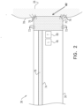
- FIG. 2 is a schematic cross-sectional longitudinal view of distal end 36.
- medical probe 22 comprises location electrode 46 and an ablation electrode 70 disposed at distal end 36.
- Ablation electrode 70 typically comprises a thin metal layer formed over distal end 36.
- Ablation electrode 70 is connected to RF signal generator 62 by conductors (not shown) in insertion tube 30.
- RF signal generator 62 is configured to apply RF energy to ablation electrode 70.
- ablation electrode 70 conveys applied RF energy to a region 82 of myocardial tissue 78 that is in contact with the ablation electrode 70, thereby ablating the myocardial tissue 78.
- RF signal generator 62 can, in response to instructions (i.e., power signals) from processor 42, monitor and control ablation parameters such as the level, the frequency and the duration of RF energy applied to ablation electrode 70.
- Ablation electrode 70 comprises a plurality of fluid ports 72.
- fluid ports 72 are disposed at distal end 36 within ablation electrode 70.
- Medical probe 22 also comprises a channel 74 (e.g., tubing) that is contained within insertion tube 30. A first end of channel 74 is coupled to fluid ports 72, and a second end of the channel is coupled to pump 64.
- channel 74 e.g., tubing
- Pump 64 forces irrigation fluid 76 (e.g., a saline solution) into channel 74, and fluid ports 72 convey the pumped irrigation fluid to myocardial tissue 78 in order to irrigate and thereby control the temperature of the myocardial tissue during an ablation procedure.
- irrigation fluid 76 e.g., a saline solution
- fluid ports 72 convey the pumped irrigation fluid to myocardial tissue 78 in order to irrigate and thereby control the temperature of the myocardial tissue during an ablation procedure.
- pump 64 can, in response to instructions received from processor 42, control a rate of flow of irrigation fluid 76 from the pump 64.
- Medical probe 22 further comprises a temperature sensor 80 (e.g., a thermocouple) disposed at distal end 36 of probe 22.
- Temperature sensor 80 generates a temperature signal indicating a temperature of myocardial tissue 78 in contact with ablation electrode 70.
- Temperature sensor 80 is connected to temperature module 66 by conductors (not shown) in insertion tube 30. In operation, temperature module 66 analyzes the temperature signal received from temperature sensor 80 located at the distal end 36 of the probe 22 so as to determine the temperature indicated by the temperature signal.
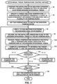
- Figure 3 is a flow diagram that schematically illustrates a method for maintaining the temperature of region 82 of myocardial tissue 78 within a specified range during an ablation procedure.
- medical professional 34 inserts distal end 36 into a chamber of heart 26 and manipulates handle 32 so that ablation electrode 70 engages a targeted region 82 of myocardial tissue 78.
- processor 42 specifies ablation procedure parameters comprising a target ablation temperature, a temperature difference threshold, a level or radio-frequency (RF) energy for ablation and a plurality of pumping rates for irrigation fluid 76.
- processor 42 can retrieve one or more of the ablation procedure parameters from memory 58.
- processor 42 can receive inputs from medical professional 34 (e.g., via input devices 60) specifying one or more of the ablation procedure parameters.
- processor 42 sets the pumping rate for pump 64 to one of the specified pumping rates.
- processor 42 can convey a pump signal to pump 64 instructing the pump to initially set the pumping rate to the intermediate pumping rate of 10 ml/minute.
- processor 42 conveys a power signal to RF signal generator 62 instructing the RF signal generator to generate a specific level of RF energy and to apply (i.e. convey) the generated RF energy to ablation electrode 70.
- pump 64 forces irrigation fluid 76 into channel 74 at the set pumping rate, and the irrigation fluid exits distal end 36 via fluid ports 72, thereby irrigating the region of myocardial tissue 78.
- processor 42 receives, from temperature sensor 80, a temperature signal indicative of a temperature of the engaged region of myocardial tissue 78.
- temperature module 66 can receive the temperature signal from temperature sensor 80, compute, based on the temperature signal, a temperature value, and convey, to processor 42, the computed temperature value (also referred to herein as the indicated temperature).
- processor 42 conveys a pump signal to pump 64 instructing the pump to set the pumping rate to the intermediate pumping rate.
- step 106 if the ablation procedure is not complete, then the method continues with step 96. If the ablation procedure is complete, then in a halt step 108, processor 42 conveys a power signal instructing RF signal generator 62 to halt generation and application of the specified level of RF energy, and the method ends.
- processor 42 conveys a pump signal to pump 64 instructing the pump to increase the pumping rate.
- processor 42 can increase the pumping rate by conveying a pump signal to pump 64 that instructs the pump to set the pumping rate to the high pumping rate.
- processor 42 can increase the pumping rate by conveying a pump signal to pump 64 that instructs the pump to increase the pumping rate by a specified value (e.g., increase by 2ml/minute).
- processor 42 can apply an algorithm such as a proportional-integral-derivative controller (PID) algorithm to analyze the indicated temperature in order to control a continuously variable flow of irrigation fluid 76.
- PID proportional-integral-derivative controller
- processor 42 can use a variation of the PID algorithm that is configured to instruct RF signal generator 62 to reduce the level of RF energy applied to ablation electrode 70.
- processor 42 conveys a pump signal to pump 64 instructing the pump to decrease the pumping rate.
- processor 42 can decrease the pumping rate by conveying a pump signal to pump 64 that instructs the pump to set the pumping rate to the low pumping rate.
- processor 42 can decrease the pumping rate by conveying a pump signal to pump 64 that instructs the pump to decrease the pumping rate by a specified value (e.g., decrease by 2ml/minute).
- processor 42 conveys, in response to the indicated temperature, pump signals instructing pump 64 to adjust the pumping rate while RF signal generator generates a constant specific level of RF energy. In other words, while continuously generating the specific level of RF energy, medical console 24 adjusts the pumping rate for irrigation fluid 76 in order to maintain the temperature of the myocardial tissue being treated at or near the target ablation temperature.
Landscapes
- Health & Medical Sciences (AREA)
- Engineering & Computer Science (AREA)
- Life Sciences & Earth Sciences (AREA)
- Surgery (AREA)
- Biomedical Technology (AREA)
- Animal Behavior & Ethology (AREA)
- Nuclear Medicine, Radiotherapy & Molecular Imaging (AREA)
- Veterinary Medicine (AREA)
- Public Health (AREA)
- General Health & Medical Sciences (AREA)
- Physics & Mathematics (AREA)
- Molecular Biology (AREA)
- Medical Informatics (AREA)
- Heart & Thoracic Surgery (AREA)
- Otolaryngology (AREA)
- Plasma & Fusion (AREA)
- Cardiology (AREA)
- Radiology & Medical Imaging (AREA)
- Surgical Instruments (AREA)
Claims (9)
- Gespültes Ablationssystem, umfassend:
eine medizinische Sonde (22), umfassend:einen flexiblen Einführschlauch (30), der ein distales Ende (36) aufweist, das konfiguriert ist, um in eine Kammer eines Herzens (26) eingeführt zu werden;eine Ablationselektrode (70), die an dem distalen Ende (36) angeordnet und konfiguriert ist, um Ablationsenergie an einen Bereich von Myokardgewebe (82) zu übermitteln, mit dem die Ablationselektrode (70) in Kontakt ist;einen Temperatursensor (80), der an dem distalen Ende (36) angeordnet und konfiguriert ist, um ein Temperatursignal auszugeben, das eine Temperatur des Bereichs von Myokardgewebe (82) angibt;einen Kanal (74), der innerhalb des Einführschlauchs enthalten und konfiguriert ist, um ein Spülfluid (76) an das distale Ende (36) abzugeben; undeinen oder mehrere Fluidanschlüsse (72), die mit dem Kanal (74) gekoppelt und an dem distalen Ende (36) angeordnet sind;einen Ablationsenergiegenerator (62), der konfiguriert ist, um ein festgelegtes Niveau der Ablationsenergie auf die Ablationselektrode anzuwenden;eine Pumpe (64), die konfiguriert ist, um das Spülfluid (76) mit einer steuerbaren Pumprate in den Kanal (74) zu drücken; undeinen Prozessor (42), der konfiguriert ist, um die Pumprate als Reaktion auf das Temperatursignal zu steuern, so dass eine Differenz zwischen einer festgelegten Ablationstemperatur, die nicht höher als 55 °C ist, und der angegebenen Temperatur nicht höher als ±2,5 °C ist, während der Ablationsenergiegenerator (62) ein konstantes Niveau der Ablationsenergie an die Ablationselektrode (70) abgibt. - Gespültes Ablationssystem nach Anspruch 1, wobei die medizinische Sonde (22) einen intrakardialen Katheter umfasst.
- Gespültes Ablationssystem nach Anspruch 1, wobei das Spülfluid (76) eine Salzlösung umfasst.
- Gespültes Ablationssystem nach Anspruch 1, wobei die festgelegte Ablationstemperatur mindestens 42 °C beträgt.
- Gespültes Ablationssystem nach Anspruch 1, wobei der Temperatursensor (80) ein Thermoelement umfasst.
- Gespültes Ablationssystem nach Anspruch 1, und umfassend ein Temperaturmodul (56), das konfiguriert ist, um das Temperatursignal von dem Temperatursensor (80) zu empfangen, um, basierend auf dem Temperatursignal, einen Temperaturwert zu berechnen, und wobei der Prozessor (42) konfiguriert ist, um die Pumprate als Reaktion auf das Temperatursignal durch Steuern der Pumprate als Reaktion auf den Temperaturwert zu steuern.
- Gespültes Ablationssystem nach Anspruch 6, wobei der Prozessor (42) konfiguriert ist, um die Pumprate als Reaktion auf das Temperatursignal durch Anwenden eines Proportional-Integral-Differential-Steuerungsalgorithmus (PID-Algorithmus) auf die angegebene Temperatur zu steuern.
- Gespültes Ablationssystem nach Anspruch 1, wobei die Ablationsenergie aus einer Liste ausgewählt wird, die aus Radiofrequenzenergie (RF-Energie), hochintensiver fokussierter Ultraschallenergie (HIFU-Energie) und gepulster Feldablationsenergie (PFA-Energie) besteht.
- Computersoftwareprodukt, das in Verbindung mit einem intrakardialen Katheter (22) betätigt wird, der einen Einführschlauch (30) und ein distales Ende (36), das in eine Kammer eines Herzens (26) eingeführt wird, einen Kanal (74), der innerhalb des Einführschlauchs (30) enthalten und konfiguriert ist, um ein Spülfluid (76) an das distale Ende (36) abzugeben, und einen oder mehrere Fluidanschlüsse (72), die mit dem Kanal (74) gekoppelt und an dem distalen Ende (36) angeordnet sind, aufweist, das Produkt umfassend ein nicht flüchtiges, computerlesbares Medium, auf dem Programmanweisungen gespeichert sind, dessen Anweisungen, wenn sie durch einen Computer gelesen werden, den Computer veranlassen:ein festgelegtes Niveau von Ablationsenergie auf eine Ablationselektrode (70) anzuwenden, die an dem distalen Ende angeordnet und konfiguriert ist, um Ablationsenergie auf einen Bereich von Myokardgewebe (82) zu übermitteln, mit dem die Ablationselektrode (70) in Kontakt ist;ein Temperatursignal von einem Temperatursensor (80) zu empfangen, der an dem distalen Ende (36) angeordnet ist, das eine Temperatur des Bereichs von Myokardgewebe (82) angibt; undeine Pumprate von Spülfluid (76) zu dem einem oder den mehreren Fluidanschlüssen (72) als Reaktion auf das Temperatursignal zu steuern, so dass eine Differenz zwischen einer festgelegten Ablationstemperatur, die nicht höher als 55 °C ist, und der angegebenen Temperatur nicht höher als ±2,5 °C ist, während ein konstantes Niveau der Ablationsenergie an die Ablationselektrode (70) abgegeben wird.
Applications Claiming Priority (1)
| Application Number | Priority Date | Filing Date | Title |
|---|---|---|---|
| US16/522,938 US12042215B2 (en) | 2019-07-26 | 2019-07-26 | Myocardial tissue ablation with narrow temperature variation |
Publications (3)
| Publication Number | Publication Date |
|---|---|
| EP3769710A1 EP3769710A1 (de) | 2021-01-27 |
| EP3769710C0 EP3769710C0 (de) | 2024-10-16 |
| EP3769710B1 true EP3769710B1 (de) | 2024-10-16 |
Family
ID=71786829
Family Applications (1)
| Application Number | Title | Priority Date | Filing Date |
|---|---|---|---|
| EP20187664.6A Active EP3769710B1 (de) | 2019-07-26 | 2020-07-24 | Myokardgewebeablation mit enger temperaturvariation |
Country Status (5)
| Country | Link |
|---|---|
| US (2) | US12042215B2 (de) |
| EP (1) | EP3769710B1 (de) |
| JP (1) | JP7551377B2 (de) |
| CN (1) | CN112294427A (de) |
| IL (1) | IL275672B2 (de) |
Families Citing this family (3)
| Publication number | Priority date | Publication date | Assignee | Title |
|---|---|---|---|---|
| US12343059B2 (en) * | 2019-11-25 | 2025-07-01 | Gyrus Acmi, Inc. | Steam ablation device for treatment of menorrhagia |
| WO2024075034A1 (en) | 2022-10-05 | 2024-04-11 | Btl Medical Technologies S.R.O. | Pulsed field ablation device and method |
| US12575881B2 (en) * | 2022-12-27 | 2026-03-17 | Biosense Webster (Israel) Ltd. | Caliper tool with toggling between multiple ablation modes |
Family Cites Families (24)
| Publication number | Priority date | Publication date | Assignee | Title |
|---|---|---|---|---|
| WO1994010922A1 (en) | 1992-11-13 | 1994-05-26 | Ep Technologies, Inc. | Cardial ablation systems using temperature monitoring |
| US5462521A (en) * | 1993-12-21 | 1995-10-31 | Angeion Corporation | Fluid cooled and perfused tip for a catheter |
| US5735846A (en) | 1994-06-27 | 1998-04-07 | Ep Technologies, Inc. | Systems and methods for ablating body tissue using predicted maximum tissue temperature |
| US5876336A (en) | 1994-10-11 | 1999-03-02 | Ep Technologies, Inc. | Systems and methods for guiding movable electrode elements within multiple-electrode structure |
| US5697377A (en) | 1995-11-22 | 1997-12-16 | Medtronic, Inc. | Catheter mapping system and method |
| US5868743A (en) | 1995-12-13 | 1999-02-09 | Children's Medical Center Corporation | Cardiac ablation system with low temperature target site identification |
| US6235022B1 (en) * | 1996-12-20 | 2001-05-22 | Cardiac Pathways, Inc | RF generator and pump apparatus and system and method for cooled ablation |
| US6063078A (en) | 1997-03-12 | 2000-05-16 | Medtronic, Inc. | Method and apparatus for tissue ablation |
| US5944022A (en) | 1997-04-28 | 1999-08-31 | American Cardiac Ablation Co. Inc. | Catheter positioning system |
| US6537272B2 (en) * | 1998-07-07 | 2003-03-25 | Medtronic, Inc. | Apparatus and method for creating, maintaining, and controlling a virtual electrode used for the ablation of tissue |
| US6210406B1 (en) * | 1998-12-03 | 2001-04-03 | Cordis Webster, Inc. | Split tip electrode catheter and signal processing RF ablation system |
| US6611699B2 (en) * | 2001-06-28 | 2003-08-26 | Scimed Life Systems, Inc. | Catheter with an irrigated composite tip electrode |
| US8920411B2 (en) * | 2006-06-28 | 2014-12-30 | Kardium Inc. | Apparatus and method for intra-cardiac mapping and ablation |
| CN101502442B (zh) * | 2008-02-05 | 2011-06-01 | 北京迈迪顶峰医疗科技有限公司 | 射频消融系统、消融控制器及射频消融装置 |
| US9277961B2 (en) * | 2009-06-12 | 2016-03-08 | Advanced Cardiac Therapeutics, Inc. | Systems and methods of radiometrically determining a hot-spot temperature of tissue being treated |
| US8954161B2 (en) * | 2012-06-01 | 2015-02-10 | Advanced Cardiac Therapeutics, Inc. | Systems and methods for radiometrically measuring temperature and detecting tissue contact prior to and during tissue ablation |
| US8834388B2 (en) * | 2010-04-30 | 2014-09-16 | Medtronic Ablation Frontiers Llc | Method and apparatus to regulate a tissue temperature |
| US9855094B2 (en) | 2010-12-28 | 2018-01-02 | St. Jude Medical, Atrial Fibrillation Division, Inc. | Multi-rate fluid flow and variable power delivery for ablation electrode assemblies used in catheter ablation procedures |
| WO2016161209A1 (en) * | 2015-03-31 | 2016-10-06 | St. Jude Medical, Cardiology Division, Inc. | Methods and devices for delivering pulsed rf energy during catheter ablation |
| CN204600671U (zh) * | 2015-04-30 | 2015-09-02 | 重庆润泽医药有限公司 | 一种具有自动滴水断电功能的电凝镊系统 |
| US10675080B2 (en) * | 2015-11-25 | 2020-06-09 | Smith & Nephew, Inc. | System and methods of controlling temperature related to electrosurgical procedures |
| EP3451961B1 (de) * | 2016-05-02 | 2024-12-04 | Affera, Inc. | System umfassend einen katheter und eine expandierbare elektrode |
| US11020178B2 (en) * | 2017-03-14 | 2021-06-01 | Biosense Webster (Israel) Ltd. | Simultaneous control of power and irrigation during ablation |
| US11918277B2 (en) * | 2018-07-16 | 2024-03-05 | Thermedical, Inc. | Inferred maximum temperature monitoring for irrigated ablation therapy |
-
2019
- 2019-07-26 US US16/522,938 patent/US12042215B2/en active Active
-
2020
- 2020-06-25 IL IL275672A patent/IL275672B2/en unknown
- 2020-07-22 JP JP2020125133A patent/JP7551377B2/ja active Active
- 2020-07-24 CN CN202010722889.XA patent/CN112294427A/zh active Pending
- 2020-07-24 EP EP20187664.6A patent/EP3769710B1/de active Active
-
2024
- 2024-06-26 US US18/754,436 patent/US20240341845A1/en active Pending
Also Published As
| Publication number | Publication date |
|---|---|
| IL275672B1 (en) | 2025-03-01 |
| EP3769710A1 (de) | 2021-01-27 |
| US20210022802A1 (en) | 2021-01-28 |
| US20240341845A1 (en) | 2024-10-17 |
| JP7551377B2 (ja) | 2024-09-17 |
| EP3769710C0 (de) | 2024-10-16 |
| JP2021020064A (ja) | 2021-02-18 |
| US12042215B2 (en) | 2024-07-23 |
| IL275672B2 (en) | 2025-07-01 |
| IL275672A (en) | 2021-01-31 |
| CN112294427A (zh) | 2021-02-02 |
Similar Documents
| Publication | Publication Date | Title |
|---|---|---|
| CN112451081B (zh) | 根据分段电极的接触的动态消融和感测 | |
| JP7238034B2 (ja) | 温度制御された短時間アブレーション | |
| JP7114282B2 (ja) | アブレーション中の電力及び灌流の同時制御 | |
| US10973575B2 (en) | Temperature controlled short duration ablation | |
| US20240341845A1 (en) | Myocardial tissue ablation with narrow temperature variation | |
| US10973574B2 (en) | Temperature controlled short duration ablation | |
| US10507058B2 (en) | Temperature controlled short duration ablation | |
| JP7330706B2 (ja) | 可変温度限界を有する電力制御式の短時間アブレーション | |
| JP7455610B2 (ja) | エネルギー誘導高周波(rf)アブレーション | |
| US20250177040A1 (en) | Temperature controlled short duration ablation with resistive heating | |
| RU2737762C1 (ru) | Коррекция скорости орошения при радиочастотной (рч) абляции в ответ на изменение усилия контакта | |
| US20240024018A1 (en) | Ablation of lesions of low-medium depths using ultrahigh radiofrequency (rf) power for ultrashort durations |
Legal Events
| Date | Code | Title | Description |
|---|---|---|---|
| PUAI | Public reference made under article 153(3) epc to a published international application that has entered the european phase |
Free format text: ORIGINAL CODE: 0009012 |
|
| STAA | Information on the status of an ep patent application or granted ep patent |
Free format text: STATUS: THE APPLICATION HAS BEEN PUBLISHED |
|
| AK | Designated contracting states |
Kind code of ref document: A1 Designated state(s): AL AT BE BG CH CY CZ DE DK EE ES FI FR GB GR HR HU IE IS IT LI LT LU LV MC MK MT NL NO PL PT RO RS SE SI SK SM TR |
|
| AX | Request for extension of the european patent |
Extension state: BA ME |
|
| STAA | Information on the status of an ep patent application or granted ep patent |
Free format text: STATUS: REQUEST FOR EXAMINATION WAS MADE |
|
| 17P | Request for examination filed |
Effective date: 20210517 |
|
| RBV | Designated contracting states (corrected) |
Designated state(s): AL AT BE BG CH CY CZ DE DK EE ES FI FR GB GR HR HU IE IS IT LI LT LU LV MC MK MT NL NO PL PT RO RS SE SI SK SM TR |
|
| RAP3 | Party data changed (applicant data changed or rights of an application transferred) |
Owner name: BIOSENSE WEBSTER (ISRAEL) LTD. |
|
| GRAP | Despatch of communication of intention to grant a patent |
Free format text: ORIGINAL CODE: EPIDOSNIGR1 |
|
| STAA | Information on the status of an ep patent application or granted ep patent |
Free format text: STATUS: GRANT OF PATENT IS INTENDED |
|
| INTG | Intention to grant announced |
Effective date: 20240716 |
|
| RIC1 | Information provided on ipc code assigned before grant |
Ipc: A61N 7/02 20060101ALN20240710BHEP Ipc: A61B 18/18 20060101ALN20240710BHEP Ipc: A61B 18/12 20060101ALN20240710BHEP Ipc: A61B 18/00 20060101ALN20240710BHEP Ipc: A61B 18/14 20060101AFI20240710BHEP |
|
| GRAS | Grant fee paid |
Free format text: ORIGINAL CODE: EPIDOSNIGR3 |
|
| GRAA | (expected) grant |
Free format text: ORIGINAL CODE: 0009210 |
|
| STAA | Information on the status of an ep patent application or granted ep patent |
Free format text: STATUS: THE PATENT HAS BEEN GRANTED |
|
| AK | Designated contracting states |
Kind code of ref document: B1 Designated state(s): AL AT BE BG CH CY CZ DE DK EE ES FI FR GB GR HR HU IE IS IT LI LT LU LV MC MK MT NL NO PL PT RO RS SE SI SK SM TR |
|
| REG | Reference to a national code |
Ref country code: GB Ref legal event code: FG4D |
|
| REG | Reference to a national code |
Ref country code: CH Ref legal event code: EP Ref country code: DE Ref legal event code: R096 Ref document number: 602020039445 Country of ref document: DE |
|
| REG | Reference to a national code |
Ref country code: IE Ref legal event code: FG4D |
|
| U01 | Request for unitary effect filed |
Effective date: 20241113 |
|
| U07 | Unitary effect registered |
Designated state(s): AT BE BG DE DK EE FI FR IT LT LU LV MT NL PT RO SE SI Effective date: 20241120 |
|
| PG25 | Lapsed in a contracting state [announced via postgrant information from national office to epo] |
Ref country code: IS Free format text: LAPSE BECAUSE OF FAILURE TO SUBMIT A TRANSLATION OF THE DESCRIPTION OR TO PAY THE FEE WITHIN THE PRESCRIBED TIME-LIMIT Effective date: 20250216 Ref country code: HR Free format text: LAPSE BECAUSE OF FAILURE TO SUBMIT A TRANSLATION OF THE DESCRIPTION OR TO PAY THE FEE WITHIN THE PRESCRIBED TIME-LIMIT Effective date: 20241016 |
|
| PG25 | Lapsed in a contracting state [announced via postgrant information from national office to epo] |
Ref country code: ES Free format text: LAPSE BECAUSE OF FAILURE TO SUBMIT A TRANSLATION OF THE DESCRIPTION OR TO PAY THE FEE WITHIN THE PRESCRIBED TIME-LIMIT Effective date: 20241016 |
|
| PG25 | Lapsed in a contracting state [announced via postgrant information from national office to epo] |
Ref country code: NO Free format text: LAPSE BECAUSE OF FAILURE TO SUBMIT A TRANSLATION OF THE DESCRIPTION OR TO PAY THE FEE WITHIN THE PRESCRIBED TIME-LIMIT Effective date: 20250116 |
|
| PG25 | Lapsed in a contracting state [announced via postgrant information from national office to epo] |
Ref country code: GR Free format text: LAPSE BECAUSE OF FAILURE TO SUBMIT A TRANSLATION OF THE DESCRIPTION OR TO PAY THE FEE WITHIN THE PRESCRIBED TIME-LIMIT Effective date: 20250117 |
|
| PG25 | Lapsed in a contracting state [announced via postgrant information from national office to epo] |
Ref country code: PL Free format text: LAPSE BECAUSE OF FAILURE TO SUBMIT A TRANSLATION OF THE DESCRIPTION OR TO PAY THE FEE WITHIN THE PRESCRIBED TIME-LIMIT Effective date: 20241016 |
|
| PG25 | Lapsed in a contracting state [announced via postgrant information from national office to epo] |
Ref country code: RS Free format text: LAPSE BECAUSE OF FAILURE TO SUBMIT A TRANSLATION OF THE DESCRIPTION OR TO PAY THE FEE WITHIN THE PRESCRIBED TIME-LIMIT Effective date: 20250116 |
|
| PG25 | Lapsed in a contracting state [announced via postgrant information from national office to epo] |
Ref country code: SM Free format text: LAPSE BECAUSE OF FAILURE TO SUBMIT A TRANSLATION OF THE DESCRIPTION OR TO PAY THE FEE WITHIN THE PRESCRIBED TIME-LIMIT Effective date: 20241016 |
|
| PGFP | Annual fee paid to national office [announced via postgrant information from national office to epo] |
Ref country code: GB Payment date: 20250605 Year of fee payment: 6 |
|
| U20 | Renewal fee for the european patent with unitary effect paid |
Year of fee payment: 6 Effective date: 20250606 |
|
| PG25 | Lapsed in a contracting state [announced via postgrant information from national office to epo] |
Ref country code: SK Free format text: LAPSE BECAUSE OF FAILURE TO SUBMIT A TRANSLATION OF THE DESCRIPTION OR TO PAY THE FEE WITHIN THE PRESCRIBED TIME-LIMIT Effective date: 20241016 |
|
| PG25 | Lapsed in a contracting state [announced via postgrant information from national office to epo] |
Ref country code: CZ Free format text: LAPSE BECAUSE OF FAILURE TO SUBMIT A TRANSLATION OF THE DESCRIPTION OR TO PAY THE FEE WITHIN THE PRESCRIBED TIME-LIMIT Effective date: 20241016 |
|
| PLBE | No opposition filed within time limit |
Free format text: ORIGINAL CODE: 0009261 |
|
| STAA | Information on the status of an ep patent application or granted ep patent |
Free format text: STATUS: NO OPPOSITION FILED WITHIN TIME LIMIT |
|
| 26N | No opposition filed |
Effective date: 20250717 |
|
| REG | Reference to a national code |
Ref country code: CH Ref legal event code: H13 Free format text: ST27 STATUS EVENT CODE: U-0-0-H10-H13 (AS PROVIDED BY THE NATIONAL OFFICE) Effective date: 20260224 |