EP3769706A1 - Cryoprobe - Google Patents
Cryoprobe Download PDFInfo
- Publication number
- EP3769706A1 EP3769706A1 EP19187779.4A EP19187779A EP3769706A1 EP 3769706 A1 EP3769706 A1 EP 3769706A1 EP 19187779 A EP19187779 A EP 19187779A EP 3769706 A1 EP3769706 A1 EP 3769706A1
- Authority
- EP
- European Patent Office
- Prior art keywords
- capillary tube
- cryoprobe
- section
- tension element
- lumen
- Prior art date
- Legal status (The legal status is an assumption and is not a legal conclusion. Google has not performed a legal analysis and makes no representation as to the accuracy of the status listed.)
- Pending
Links
- 239000000463 material Substances 0.000 claims description 12
- 239000012530 fluid Substances 0.000 claims description 10
- 229910000831 Steel Inorganic materials 0.000 claims description 5
- 239000010959 steel Substances 0.000 claims description 5
- 230000005540 biological transmission Effects 0.000 claims description 2
- 210000001635 urinary tract Anatomy 0.000 claims description 2
- 229910001220 stainless steel Inorganic materials 0.000 claims 1
- 239000010935 stainless steel Substances 0.000 claims 1
- 239000000523 sample Substances 0.000 description 17
- 238000005452 bending Methods 0.000 description 13
- 238000001574 biopsy Methods 0.000 description 5
- 239000002131 composite material Substances 0.000 description 2
- 238000001816 cooling Methods 0.000 description 2
- 239000013013 elastic material Substances 0.000 description 2
- 238000010438 heat treatment Methods 0.000 description 2
- 239000002184 metal Substances 0.000 description 2
- 229910052751 metal Inorganic materials 0.000 description 2
- 239000007769 metal material Substances 0.000 description 2
- 239000004033 plastic Substances 0.000 description 2
- 230000002792 vascular Effects 0.000 description 2
- 241001164374 Calyx Species 0.000 description 1
- 229920000049 Carbon (fiber) Polymers 0.000 description 1
- RYGMFSIKBFXOCR-UHFFFAOYSA-N Copper Chemical compound [Cu] RYGMFSIKBFXOCR-UHFFFAOYSA-N 0.000 description 1
- 239000004696 Poly ether ether ketone Substances 0.000 description 1
- 238000000137 annealing Methods 0.000 description 1
- 239000004760 aramid Substances 0.000 description 1
- 229920006231 aramid fiber Polymers 0.000 description 1
- JUPQTSLXMOCDHR-UHFFFAOYSA-N benzene-1,4-diol;bis(4-fluorophenyl)methanone Chemical compound OC1=CC=C(O)C=C1.C1=CC(F)=CC=C1C(=O)C1=CC=C(F)C=C1 JUPQTSLXMOCDHR-UHFFFAOYSA-N 0.000 description 1
- 239000004917 carbon fiber Substances 0.000 description 1
- 239000012809 cooling fluid Substances 0.000 description 1
- 239000010949 copper Substances 0.000 description 1
- 229910052802 copper Inorganic materials 0.000 description 1
- 239000000835 fiber Substances 0.000 description 1
- 230000003993 interaction Effects 0.000 description 1
- 229910052755 nonmetal Inorganic materials 0.000 description 1
- 229920002530 polyetherether ketone Polymers 0.000 description 1
Images
Classifications
-
- A—HUMAN NECESSITIES
- A61—MEDICAL OR VETERINARY SCIENCE; HYGIENE
- A61B—DIAGNOSIS; SURGERY; IDENTIFICATION
- A61B10/00—Other methods or instruments for diagnosis, e.g. instruments for taking a cell sample, for biopsy, for vaccination diagnosis; Sex determination; Ovulation-period determination; Throat striking implements
- A61B10/02—Instruments for taking cell samples or for biopsy
- A61B10/0233—Pointed or sharp biopsy instruments
-
- A—HUMAN NECESSITIES
- A61—MEDICAL OR VETERINARY SCIENCE; HYGIENE
- A61B—DIAGNOSIS; SURGERY; IDENTIFICATION
- A61B10/00—Other methods or instruments for diagnosis, e.g. instruments for taking a cell sample, for biopsy, for vaccination diagnosis; Sex determination; Ovulation-period determination; Throat striking implements
- A61B10/02—Instruments for taking cell samples or for biopsy
- A61B10/04—Endoscopic instruments
-
- A—HUMAN NECESSITIES
- A61—MEDICAL OR VETERINARY SCIENCE; HYGIENE
- A61B—DIAGNOSIS; SURGERY; IDENTIFICATION
- A61B18/00—Surgical instruments, devices or methods for transferring non-mechanical forms of energy to or from the body
- A61B18/02—Surgical instruments, devices or methods for transferring non-mechanical forms of energy to or from the body by cooling, e.g. cryogenic techniques
-
- A—HUMAN NECESSITIES
- A61—MEDICAL OR VETERINARY SCIENCE; HYGIENE
- A61L—METHODS OR APPARATUS FOR STERILISING MATERIALS OR OBJECTS IN GENERAL; DISINFECTION, STERILISATION OR DEODORISATION OF AIR; CHEMICAL ASPECTS OF BANDAGES, DRESSINGS, ABSORBENT PADS OR SURGICAL ARTICLES; MATERIALS FOR BANDAGES, DRESSINGS, ABSORBENT PADS OR SURGICAL ARTICLES
- A61L29/00—Materials for catheters, medical tubing, cannulae, or endoscopes or for coating catheters
- A61L29/02—Inorganic materials
-
- A—HUMAN NECESSITIES
- A61—MEDICAL OR VETERINARY SCIENCE; HYGIENE
- A61B—DIAGNOSIS; SURGERY; IDENTIFICATION
- A61B10/00—Other methods or instruments for diagnosis, e.g. instruments for taking a cell sample, for biopsy, for vaccination diagnosis; Sex determination; Ovulation-period determination; Throat striking implements
- A61B10/02—Instruments for taking cell samples or for biopsy
- A61B2010/0208—Biopsy devices with actuators, e.g. with triggered spring mechanisms
-
- A—HUMAN NECESSITIES
- A61—MEDICAL OR VETERINARY SCIENCE; HYGIENE
- A61B—DIAGNOSIS; SURGERY; IDENTIFICATION
- A61B10/00—Other methods or instruments for diagnosis, e.g. instruments for taking a cell sample, for biopsy, for vaccination diagnosis; Sex determination; Ovulation-period determination; Throat striking implements
- A61B10/02—Instruments for taking cell samples or for biopsy
- A61B10/04—Endoscopic instruments
- A61B2010/045—Needles
-
- A—HUMAN NECESSITIES
- A61—MEDICAL OR VETERINARY SCIENCE; HYGIENE
- A61B—DIAGNOSIS; SURGERY; IDENTIFICATION
- A61B17/00—Surgical instruments, devices or methods, e.g. tourniquets
- A61B17/00234—Surgical instruments, devices or methods, e.g. tourniquets for minimally invasive surgery
- A61B2017/00292—Surgical instruments, devices or methods, e.g. tourniquets for minimally invasive surgery mounted on or guided by flexible, e.g. catheter-like, means
- A61B2017/003—Steerable
- A61B2017/00318—Steering mechanisms
- A61B2017/00323—Cables or rods
-
- A—HUMAN NECESSITIES
- A61—MEDICAL OR VETERINARY SCIENCE; HYGIENE
- A61B—DIAGNOSIS; SURGERY; IDENTIFICATION
- A61B18/00—Surgical instruments, devices or methods for transferring non-mechanical forms of energy to or from the body
- A61B2018/00315—Surgical instruments, devices or methods for transferring non-mechanical forms of energy to or from the body for treatment of particular body parts
- A61B2018/00505—Urinary tract
- A61B2018/00511—Kidney
-
- A—HUMAN NECESSITIES
- A61—MEDICAL OR VETERINARY SCIENCE; HYGIENE
- A61B—DIAGNOSIS; SURGERY; IDENTIFICATION
- A61B18/00—Surgical instruments, devices or methods for transferring non-mechanical forms of energy to or from the body
- A61B2018/00982—Surgical instruments, devices or methods for transferring non-mechanical forms of energy to or from the body combined with or comprising means for visual or photographic inspections inside the body, e.g. endoscopes
-
- A—HUMAN NECESSITIES
- A61—MEDICAL OR VETERINARY SCIENCE; HYGIENE
- A61B—DIAGNOSIS; SURGERY; IDENTIFICATION
- A61B18/00—Surgical instruments, devices or methods for transferring non-mechanical forms of energy to or from the body
- A61B18/02—Surgical instruments, devices or methods for transferring non-mechanical forms of energy to or from the body by cooling, e.g. cryogenic techniques
- A61B2018/0212—Surgical instruments, devices or methods for transferring non-mechanical forms of energy to or from the body by cooling, e.g. cryogenic techniques using an instrument inserted into a body lumen, e.g. catheter
-
- A—HUMAN NECESSITIES
- A61—MEDICAL OR VETERINARY SCIENCE; HYGIENE
- A61B—DIAGNOSIS; SURGERY; IDENTIFICATION
- A61B18/00—Surgical instruments, devices or methods for transferring non-mechanical forms of energy to or from the body
- A61B18/02—Surgical instruments, devices or methods for transferring non-mechanical forms of energy to or from the body by cooling, e.g. cryogenic techniques
- A61B2018/0231—Characteristics of handpieces or probes
- A61B2018/0262—Characteristics of handpieces or probes using a circulating cryogenic fluid
- A61B2018/0268—Characteristics of handpieces or probes using a circulating cryogenic fluid with restriction of flow
Definitions
- the invention relates to a cryoprobe which is particularly suitable for taking tissue samples in highly branched vascular systems, such as, for example, vascular systems, such as for example for taking tissue samples in the upper urinary tract, especially in the renal calyx system.
- highly branched vascular systems such as, for example, vascular systems, such as for example for taking tissue samples in the upper urinary tract, especially in the renal calyx system.
- Cryoprobes for tissue biopsy are known in principle.
- the DE 10 2011 000 004 B4 a flexible cryoprobe with a tube which has a lumen and at the distal end of which a metallic head in the form of a cup is arranged, the diameter of which corresponds to the diameter of the tube and which has a rounded base at its distal end.
- a capillary tube is disposed in the tube which extends the entire length of the tube and terminates inside the head. The capillary tube is used to introduce cryofluid into the head in order to cool it.
- the distal end of the probe When taking a tissue sample, the distal end of the probe is cooled down to such an extent that the tissue to be taken freezes to the head of the probe. The tissue then has to be separated from the unfrozen tissue, ie torn off and guided out of the patient's lumen with the probe will. In the case of angled lumens, it is also important to be able to bend the probe with a small bending radius, whereby a bend of significantly more than 90 ° may be desired.
- the cryoprobe according to the invention comprises a tube which is provided at its end with a head which is used to remove tissue.
- a capillary tube extends through the lumen of the tube to supply the head with a cryofluid.
- the capillary tube is a line whose pressure resistance is matched to the cryofluid to be used.
- a puller wire is additionally arranged, which is used to transmit pulling forces from the head to a proximal end of the cryoprobe.
- This enables the use of a capillary tube that is highly flexible in one or more sections or as a whole and, on the other hand, also enables the necessary tensile forces to be transmitted from the proximal end to the head in order to tear off tissue that is frozen on the head and thus take a tissue sample.
- the cryoprobe according to the invention is so flexible that it can be angled at large angles with little use of force, and it combines this with high tensile strength.
- the cryoprobe can be designed very filigree and have an outer diameter of less than 1.2 mm, so that it can also be used in very narrow endoscopes.
- bending angles i.e. bending of more than 150 °, preferably more than 160 °, can be achieved. Due to the high flexibility of the cryoprobe, the bending can be carried out with little effort that can be exerted by the endoscope.
- the capillary tube is preferably made of a material in which an increase or a decrease in its tensile strength can be achieved through an action, for example a heat treatment. Furthermore, the capillary tube is preferably treated or machined so that it has at least one section in which the tensile strength of the material and thus also the flexural strength of the capillary tube is reduced compared to the tensile strength and thus also the flexural strength of the rest of the capillary tube. This section of reduced tensile strength and reduced flexural rigidity is preferably arranged in that distal section of the cryoprobe which is angled from the endoscope in use.
- the capillary tube consists, for example, of steel or another material that is resistant to tension and is rigid.
- the steel can be annealed, for example.
- the puller wire is used to transmit pulling forces from the proximal end to the head of the probe. At least he is arranged spanning the soft portion of the capillary tube.
- the pull wire is connected to the head of the instrument at the distal end in a tensile manner.
- the pull wire can be connected directly to the head or also to a section of the capillary tube which is resistant to tension and which in turn can be connected to the head.
- the distal end of the puller wire can be connected to the distal end of the probe or, as is preferred, to the distal part of the capillary tube which is resistant to tension.
- the puller wire thus spans at least the section of the capillary that has reduced flexural rigidity.
- the pull wire can be connected to the capillary tube in a tensile manner, for example via weld spots, weld seams or other types of connection.
- the puller wire preferably lies parallel to the capillary tube, i.e. the connection points between the puller wire and capillary tube are arranged in the same angular position with respect to the capillary cross section. This enables free angular movement of the probe in all radial directions.
- the diameter of the puller wire is preferably less than the difference between the diameter of the lumen and the outer diameter of the capillary tube. Both the capillary tube and the puller wire thus remain movable radially and in the circumferential direction in the lumen. When the probe is bent, in which the puller wire lies radially outward with respect to the bending radius, at least the middle section of the puller wire can migrate in the lumen and onto the opposite side of the lumen. As a result, the puller wire does not offer any resistance to bending in this case either.
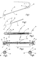
- an endoscope 10 is illustrated in which a cryoprobe 11 is inserted. This extends from the proximal end 12 of the endoscope to its distal end 14, which can be moved via operating elements 13.
- the endoscope 10 has an elongated shaft 15 through whose channel the cryoprobe 11 is guided. The distal end 16 of the cryoprobe 11 can be drawn into the shaft 15 or pushed out of it.
- the outer diameter of the cryoprobe 11 is preferably somewhat smaller than the inner diameter of the channel provided in the shaft 15.
- the control elements 13 are used to control the distal end 14 of the shaft 15, in particular to bend it in a targeted manner against the axial direction 17, which, as shown in FIG Figure 2 shows, lies along the shaft 15.
- the angle ⁇ that can be achieved here is preferably greater than 90 °, more preferably greater than 140 ° and, in the preferred case, greater than 160 °.
- the bending radius is less than 20 mm, preferably less than 15 mm, with an outer diameter of the shaft 15 of less than 3.3 mm.
- the cryoprobe 11 is in the region of its distal end 16 in Figure 3 illustrated separately. It has a hose 18, at the distal end 19 of which a head 20 is connected in a fluid-tight manner.
- the tube 18 encloses a lumen 21 and is designed to be highly flexible at least at the section adjoining the head 20.
- the head 20 is in Figure 3 illustrated schematically. It preferably has an outer diameter which corresponds to the outer diameter of the hose 18. At its distal end, the head 20 is closed by a flat, rounded or otherwise configured base.
- the hose is also provided with a fluid channel 22 which is used to bring cooling fluid to the head 20 or into it.
- the fluid channel 22 can be formed by a capillary tube 22a which extends through the lumen 21 of the tube 18.
- the capillary tube 22a can be connected to the head 20 at its head-side end 23.
- the connection can be made by connecting elements which are not further illustrated or, as shown in FIG Figure 3 can be seen, a weld point or the like can be made directly through a weld seam 24.
- the capillary tube 22a can be open at its distal end or can be provided with a nozzle. the nozzle can also be molded onto the capillary tube.
- the capillary tube 22a is preferably made of a tensile steel, for example X2CrNiMo 1.4404 or X2CrNiMo 1.4401.
- the material of the capillary tube 22a preferably has a tensile strength of more than 900 N / mm 2 .
- the capillary tube 22a is used to introduce cryofluid into the interior of the head 20 for cooling the same and also for the transmission of tensile forces during biopsy removal.
- the capillary tube 22a is not designed to be tensile strength throughout.
- the capillary tube 22a is reduced in its tensile strength and thus also in its flexural rigidity by a heat treatment, for example by soft annealing.
- the tensile strength in this section is preferably less than 700 N / mm 2 .
- the capillary tube 22a has thus also grown in section 25 of the pressure load exerted by the cryofluid. It is also flexible so that the cryoprobe can be angled with a small bending radius, as shown in Figure 2 is indicated.
- the section 25 is not tensile enough to transmit the necessary tensile forces for biopsy removal.
- the section 25 is bridged by a tension element 26, which in the present exemplary embodiment is a tension wire 27.
- a tension element 26 which in the present exemplary embodiment is a tension wire 27.
- This consists of a material with high tensile strength which, in interaction with the capillary tube 22a, transmits the tensile forces required for biopsy removal within its elastic material stress.
- the pull wire 27 is connected at both ends by welded connections 28, 29, for example welded seams, to the capillary tube 22a, which also transmits the tensile forces within its elastic material stress.
- the distance of the weld seams 28, 29 from one another, measured along the length of the capillary tube 22a, is in any case greater than the length of the section which is reduced in its tensile strength and flexural strength compared to the rest of the capillary tube 22a.
- FIGS. 5 and 6 illustrate this and also show that the welded connections 28, 29 are arranged at the two ends of the puller wire 27 at the same radial position of the capillary tube 22a. Between the two welded connections 28, 29, the pull wire 27 rests in an untensioned (slack) and laterally movable manner on the capillary tube 22a or runs at a small distance therefrom as it does Figure 3 indicates. In the alignment, the pull wire 27 is oriented largely parallel to the capillary tube 22a.
- the cryoprobe 11 with the endoscope 10 is inserted into a lumen of the patient and the distal end 16 with the patient's tissue to be sampled brought into contact or stabbed into this.
- the introduction of the cryoprobe 11 into the endoscope 10 is particularly facilitated by the fact that the cryoprobe 11 is stiff almost along its entire length, ie stiffer than the section 25, in accordance with the stiffness of the capillary tube 22a.
- the instrument is flexible overall. Only the part of the length determined by the section 25 is more flexible and easier to bend.
- the endoscope can, like Figure 2 shows, if necessary, to be angled at an angle greater than 160 °.
- the endoscope 10 and the cryoprobe 11 can be inserted into narrow and highly angled vessels of a patient.
- the cryoprobe 11 is dimensioned such that the section 25 lies in the area of the bending point of the endoscope.
- the length of the section 25 is preferably so great that the angling is possible both when the head 20 is still at the opening of the distal end 14 of the shaft 15, as well as when the head 20, as Figures 1 and 2 show, is pushed out of the shaft 15.
- the length of the section 25 is preferably more than a few centimeters, preferably more than 10 cm.
- the bending of the endoscope 10 is only slightly hindered by the rigidity of the capillary tube 22a, because the section 25 is designed to be correspondingly flexible.
- the tube 18 is also made of a flexible material, preferably a plastic, preferably a PEEK or PA, which only slightly hinders the bending of the endoscope.
- the tension wire 27, which is stiff, also does not offer any significant resistance to the bending due to its small diameter.
- the diameter of the pulling element 26, in particular of the pulling wire 27, is smaller than the diameter of the capillary tube 22a.
- cryofluid is applied to the inside of the head 20, which is introduced into the head 20 through the capillary tube 22a.
- parts of the tissue to be sampled freeze on it.
- the cryoprobe 11 is moved in the proximal direction.
- the tissue frozen onto the head 20 is torn off from the remaining tissue.
- the force required for this is first transmitted via the capillary tube 22a to the welded connection 29 and from there via the pull wire 27 to the welded connection 28. From there, the flow of force goes to the head 20 via the capillary tube 22a.
- the pull wire 27 thus bridges the non-tensile section 25 in terms of force.
- the capillary tube 22a from the proximal end to the connection point 28 can be formed completely or in one or more sections of a metallic or non-metallic material which is more flexible than the rest of the capillary tube 22a.
- the capillary tube 22a can be completely or completely up to its distal end be partially made of a material that is more flexible and less tensile strength than the rest of the capillary tube 22a.
- the capillary tube 22a in its entirety or in one or more sections from a flexible, non-rigid and non-tensile material.
- the pulling element 26 is connected at its distal end to the head 20 or an element connected to it, while its proximal end is connected to the proximal end of the cryoprobe 11.
- a pull wire 27 a tensile metal band, a wire bundle, a rope, a pipe or the like can also be used as the pulling element 26.
- a metallic tension element 26 a non-metallic tension element can also be used, the ends of which are also connected to the capillary tube 22a in order to bridge at least the section 25 or longer parts of the capillary tube 22a or the entire capillary tube 22a.
- the tension element 26 can also be designed as a monofilament or as a rope made from a non-metallic material or from a composite material, for example a fiber composite material.
- the capillary tube is only flexible in its section 25.
- This section 25 typically has a length of 10 cm to 30 cm and is limited to a length which is the sum of the length of the active angled area of the endoscope and the maximum extension length of the cryoprobe 11 from the endoscope 10 during use.
- the length of the tension element 26 is dimensioned such that at least the entire length of the flexible region 25 of the capillary tube 22a is bridged.
- the tension element 26 is anchored proximally in a force-transmitting manner on the capillary tube 22a and distally on the head 20 or on the capillary tube 22a, provided that the flexible section does not extend up to this point.
- the cryoprobe 11 can be easily handled in the usual way. In addition, it is ensured that the tension element 26 restricts the cross section of the lumen 21 only over a short length of the tube 18 and thus does not significantly reduce the flow resistance therein.
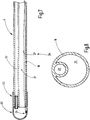
- Figure 7 illustrates a modified embodiment of the instrument 11 for which the previous description applies correspondingly on the basis of the reference symbols introduced.
- the instrument 11 is after Figure 7 compared to the instrument 11 after the Figures 3 to 6 modified.
- Its tube 18 is designed with two lumen, in that the fluid channel 22 is arranged parallel to the lumen 21.
- Figure 8 illustrates an exemplary channel arrangement in an enlarged cross section. While the fluid channel 22 can have a circular cross section, for example, the cross section of the lumen 21 can be configured differently from the circular shape Figure 8 illustrated or also circular.
- a pulling element 26 is in turn assigned to the hose 18, for example in the form of a pulling wire 27, which for example extends through the lumen 21 and can be connected to the head 20 at its distal end at a weld 24.
- the puller wire 27 can extend as far as the proximal end of the tube 18 in order to transmit tensile forces to the head 20 from there.
- the tension element 26 can be metal or also a non-metal such as carbon fibers, aramid fibers or the like.
- the tension element 26 can alternatively be embedded in the wall of the hose 18.
- the tension element 26 is in any case preferably according to all embodiments Figure 3 to Figure 8 arranged in the longitudinal direction of the instrument 11, wherein the pulling element 26 is preferably arranged straight.
- the tension element preferably wraps around neither the lumen 21 nor the fluid channel 22, but is arranged essentially parallel to them.
- a cryoprobe according to the invention has a head 20 to which cryofluid is fed via a capillary tube 22a.
- the capillary tube 22a has a flexible section 25 which is bridged by a tension element 26. In this way, an easy-to-handle cryoprobe 11 is obtained, which can be angled easily and very widely and which nevertheless transmits the tensile forces required for taking the sample.
Abstract
Eine erfindungsgemäße Kryosonde weist einen Kopf (20) auf, dem über ein Kapillarrohr (22a) Kryofluid zugeführt wird. Zur Abfuhr des Kryofluids dient ein Schlauch (18), durch dessen Lumen (21) sich das Kapillarrohr (22a) erstreckt. Das Kapillarrohr (22a) weist einen biegeweichen Abschnitt (55) auf, der von einem Zugelement (26) überbrückt wird. Auf diese Weise wird eine gut handhabbare Kryosonde (11) erhalten, die sich leicht und sehr weit abwinkeln lässt und dennoch die zur Probeentnahme nötigen Zugkräfte überträgt.

Description
Die Erfindung betrifft eine Kryosonde, die insbesondere zur Gewebeprobenentnahme in stark verzweigten Gefäßsystemen, wie beispielsweise Gefäßsystemen, wie beispielsweise zur Gewebeprobeentnahme im oberen Harntrakt, speziell im Nierenkelchsystem, geeignet ist.The invention relates to a cryoprobe which is particularly suitable for taking tissue samples in highly branched vascular systems, such as, for example, vascular systems, such as for example for taking tissue samples in the upper urinary tract, especially in the renal calyx system.
Kryosonden für die Gewebebiopsie sind prinzipiell bekannt. Zum Beispiel offenbart die
Ähnliche Kryosonden sind aus der
Bei der Gewebeprobenentnahme wird das distale Ende der Sonde soweit abgekühlt, dass das zu entnehmende Gewebe an dem Kopf der Sonde anfriert. Das Gewebe muss dann von dem nicht gefrorenen Gewebe getrennt, d.h., abgerissen und mit der Sonde aus dem Lumen des Patienten herausgeführt werden. Bei verwinkelten Lumen kommt es dabei zusätzlich darauf an, die Sonde mit geringem Biegeradius abwinkeln zu können, wobei eine Abwinkelung von deutlich mehr als 90° gewünscht sein kann.When taking a tissue sample, the distal end of the probe is cooled down to such an extent that the tissue to be taken freezes to the head of the probe. The tissue then has to be separated from the unfrozen tissue, ie torn off and guided out of the patient's lumen with the probe will. In the case of angled lumens, it is also important to be able to bend the probe with a small bending radius, whereby a bend of significantly more than 90 ° may be desired.
Davon ausgehend ist es Aufgabe der Erfindung, eine Kryosonde bereitzustellen, die für derart anspruchsvollen Gebrauch geeignet ist.On this basis, it is the object of the invention to provide a cryoprobe which is suitable for such demanding use.
Diese Aufgabe wird mit der Kryosonde nach Anspruch 1 erfüllt.This object is achieved with the cryoprobe according to claim 1.
Die erfindungsgemäße Kryosonde umfasst einen Schlauch, der an seinem Ende mit einem Kopf versehen ist, der zur Gewebeentnahme dient. Durch das Lumen des Schlauchs erstreckt sich ein Kapillarrohr, um den Kopf mit einem Kryofluid zu versorgen. Das Kapillarrohr ist eine Leitung, deren Druckfestigkeit auf das einzusetzende Kryofluid abgestimmt ist.The cryoprobe according to the invention comprises a tube which is provided at its end with a head which is used to remove tissue. A capillary tube extends through the lumen of the tube to supply the head with a cryofluid. The capillary tube is a line whose pressure resistance is matched to the cryofluid to be used.
In dem Lumen des Schlauchs ist zusätzlich ein Zugdraht angeordnet, der der Übertragung von Zugkräften von dem Kopf auf ein proximales Ende der Kryosonde dient. Dies ermöglicht die Nutzung eines in einem oder mehreren Abschnitten oder insgesamt hochflexiblen Kapillarrohrs und andererseits auch die Übertragung der nötigen Zugkräfte von dem proximalen Ende auf den Kopf, um an dem Kopf angefrorenes Gewebe von nicht gefrorenem Gewebe abzureißen und so eine Gewebeprobe zu entnehmen.In the lumen of the tube, a puller wire is additionally arranged, which is used to transmit pulling forces from the head to a proximal end of the cryoprobe. This enables the use of a capillary tube that is highly flexible in one or more sections or as a whole and, on the other hand, also enables the necessary tensile forces to be transmitted from the proximal end to the head in order to tear off tissue that is frozen on the head and thus take a tissue sample.
Die erfindungsgemäße Kryosonde ist so flexibel, dass sie mit geringem Krafteinsatz in großen Winkeln abgewinkelt werden kann, und sie vereint dies mit hoher Zugfestigkeit.The cryoprobe according to the invention is so flexible that it can be angled at large angles with little use of force, and it combines this with high tensile strength.
Die Kryosonde kann sehr filigran gestaltet werden und einen Außendurchmesser von weniger als 1,2 mm aufweisen, sodass sie auch in sehr engen Endoskopen einsetzbar ist. Es können mit dem erfindungsgemäßen Konzept Biegewinkel, d.h., ein Abwinkeln von mehr als 150° vorzugsweise mehr als 160° erreicht werden. Dabei kann aufgrund der hohen Flexibilität der Kryosonde das Abwinkeln mit geringem von dem Endoskop aufbringbaren Kraftaufwand durchgeführt werden.The cryoprobe can be designed very filigree and have an outer diameter of less than 1.2 mm, so that it can also be used in very narrow endoscopes. With the concept according to the invention, bending angles, i.e. bending of more than 150 °, preferably more than 160 °, can be achieved. Due to the high flexibility of the cryoprobe, the bending can be carried out with little effort that can be exerted by the endoscope.
Vorzugsweise ist das Kapillarrohr aus einem Material gefertigt, bei dem durch eine Einwirkung, beispielsweise eine Wärmebehandlung, eine Erhöhung oder eine Verminderung seiner Zugfestigkeit erzielbar ist. Weiter vorzugsweise ist das Kapillarrohr so behandelt oder bearbeitet, dass es wenigstens einen Abschnitt aufweist, in dem die Zugfestigkeit des Materials und somit auch die Biegesteifigkeit des Kapillarrohrs gegenüber der Zugfestigkeit und somit auch der Biegesteifigkeit des übrigen Kapillarrohrs reduziert ist. Dieser Abschnitt reduzierter Zugfestigkeit und reduzierter Biegesteifigkeit ist vorzugsweise in demjenigen distalen Abschnitt der Kryosonde angeordnet, der von dem Endoskop im Einsatz abgewinkelt wird. Das Kapillarrohr besteht beispielsweise aus Stahl oder einem anderen zugfesten und biegesteifen Material. In dem Abschnitt, in dem die Sonde mit geringem Biegeradius abzuwinkeln ist kann der Stahl beispielsweise weichgeglüht sein. Alternativ ist es möglich, diesen Abschnitt durch ein Kapillarrohrstück aus anderem Material zu bilden, beispielsweise Kunststoff, Kupfer oder dergleichen.The capillary tube is preferably made of a material in which an increase or a decrease in its tensile strength can be achieved through an action, for example a heat treatment. Furthermore, the capillary tube is preferably treated or machined so that it has at least one section in which the tensile strength of the material and thus also the flexural strength of the capillary tube is reduced compared to the tensile strength and thus also the flexural strength of the rest of the capillary tube. This section of reduced tensile strength and reduced flexural rigidity is preferably arranged in that distal section of the cryoprobe which is angled from the endoscope in use. The capillary tube consists, for example, of steel or another material that is resistant to tension and is rigid. In the section in which the probe is to be angled with a small bending radius, the steel can be annealed, for example. Alternatively, it is possible to form this section by a piece of capillary tube made of another material, for example plastic, copper or the like.
Der Zugdraht dient zur Übertragung von Zugkräften von dem proximalen Ende auf den Kopf der Sonde. Er ist wenigstens den weichen Abschnitt des Kapillarrohrs überspannend angeordnet. Dazu ist der Zugdraht an dem distalen Ende zugfest mit dem Kopf des Instruments verbunden. Der Zugdraht kann dazu direkt an den Kopf oder auch an einen zugfesten Abschnitt des Kapillarrohrs angeschlossen sein, das wiederum mit dem Kopf verbunden sein kann.The puller wire is used to transmit pulling forces from the proximal end to the head of the probe. At least he is arranged spanning the soft portion of the capillary tube. For this purpose, the pull wire is connected to the head of the instrument at the distal end in a tensile manner. For this purpose, the pull wire can be connected directly to the head or also to a section of the capillary tube which is resistant to tension and which in turn can be connected to the head.
Das distale Ende des Zugdrahts kann bis zum distalen Ende der Sonde oder, wie es bevorzugt wird, mit dem zugfesten distalen Teil des Kapillarrohrs verbunden sein. Damit überspannt der Zugdraht wenigstens den Abschnitt der Kapillare der eine reduzierte Biegesteifigkeit aufweist.The distal end of the puller wire can be connected to the distal end of the probe or, as is preferred, to the distal part of the capillary tube which is resistant to tension. The puller wire thus spans at least the section of the capillary that has reduced flexural rigidity.
Der Zugdraht kann beispielsweise über Schweißpunkte, Schweißnähte oder andere Verbindungsarten, zugfest mit dem Kapillarrohr verbunden sein. Vorzugsweise liegt der Zugdraht dabei parallel zu dem Kapillarrohr, d.h., die Verbindungsstellen zwischen Zugdraht und Kapillarrohr sind bezüglich des Kapillarquerschnitts in gleicher Winkelposition angeordnet. Dadurch wird eine freie Winkelbewegung der Sonde in allen Radialrichtungen ermöglicht.The pull wire can be connected to the capillary tube in a tensile manner, for example via weld spots, weld seams or other types of connection. The puller wire preferably lies parallel to the capillary tube, i.e. the connection points between the puller wire and capillary tube are arranged in the same angular position with respect to the capillary cross section. This enables free angular movement of the probe in all radial directions.
Obwohl es prinzipiell möglich ist, den biegeweichen Abschnitt des Kapillarohrs mit mehreren Zugdrähten zu überbrücken, wird es bevorzugt, lediglich einen Zugdraht vorzusehen. Es ergibt sich dabei eine gute Beweglichkeit der Kryosonde in allen Richtungen.Although it is in principle possible to bridge the pliable section of the capillary tube with several puller wires, it is preferred to provide only one puller wire. This results in good mobility of the cryoprobe in all directions.
Der Durchmesser des Zugdrahts ist vorzugsweise geringer als die Differenz zwischen dem Durchmesser des Lumens und dem Außendurchmesser des Kapillarohrs. Damit bleibt sowohl das Kapillarrohr als auch der Zugdraht in dem Lumen radial und in Umfangsrichtung beweglich. Bei einer Biegung der Sonde, bei der der Zugdraht bezüglich des Biegeradius radial außen liegt, kann zumindest der mittlere Abschnitt des Zugdrahts in dem Lumen wandern und auf die gegenüber liegenden Seite des Lumens gelangen. Dadurch setzt der Zugdraht auch in diesem Fall einer Abwinklung keinen Widerstand entgegen.The diameter of the puller wire is preferably less than the difference between the diameter of the lumen and the outer diameter of the capillary tube. Both the capillary tube and the puller wire thus remain movable radially and in the circumferential direction in the lumen. When the probe is bent, in which the puller wire lies radially outward with respect to the bending radius, at least the middle section of the puller wire can migrate in the lumen and onto the opposite side of the lumen. As a result, the puller wire does not offer any resistance to bending in this case either.
Weitere Einzelheiten vorteilhafter Ausführungsformen der Erfindung ergeben sich aus der Zeichnung, der Beschreibung und Ansprüchen. Es zeigen:
-
Figur 1 ein Endoskop mit einer erfindungsgemäßen Sonde, in schematisierter perspektivischer Darstellung, -
Figur 2 das distale Ende des Endoskops mit Sonde, in abgewinkeltem Zustand, -
Figur 3 das distale Ende der Sonde, in schematischer längsgeschnittener Darstellung, -
Figur 4 einen Ausschnitt des distalen Endes der Sonde, in schematisierter längsgeschnittener Darstellung, -
Figur 5 und 6 Schnittdarstellungen der Sonde nachFigur 4 , geschnitten entlang der Linien V-V bzw. VI-VI, -
Figur 7 eine alternative Ausführungsform des Instruments, -
Figur 8 , das Instrument nachFigur 7 im Querschnitt.
-
Figure 1 an endoscope with a probe according to the invention, in a schematic perspective illustration, -
Figure 2 the distal end of the endoscope with probe, in an angled position, -
Figure 3 the distal end of the probe, in a schematic longitudinal section, -
Figure 4 a section of the distal end of the probe, in a schematic longitudinal section, -
Figures 5 and 6 Sectional views of the probeFigure 4 , cut along the lines VV or VI-VI, -
Figure 7 an alternative embodiment of the instrument, -
Figure 8 , the instrument afterFigure 7 in cross section.
In
Die Bedienelemente 13 dienen dazu, das distale Ende 14 des Schafts 15 zu steuern, insbesondere gezielt gegen die Axialrichtung 17 abzuwinkeln, die, wie es
Die Kryosonde 11 ist im Bereich ihres distalen Endes 16 in
Der Schlauch ist außerdem mit einem Fluidkanal 22 versehen, der dazu dient, Kühlfluid an den Kopf 20 heran oder in diesen zu führen. Der Fluidkanal 22 kann durch ein Kapillarrohr 22a gebildet sein, das sich durch das Lumen 21 des Schlauchs 18 erstreckt. Das Kapillarrohr 22a kann an seinem kopfseitigen Ende 23 mit dem Kopf 20 verbunden sein. Die Verbindung kann durch nicht weiter veranschaulichte Verbindungselemente oder, wie aus
Das Kapillarrohr 22a kann an seinem distalen Ende offen oder mit einer Düse versehen sein. die Düse kann auch an dem Kapillarrohr angeformt sein. Vorzugsweise besteht das Kapillarrohr 22a aus einem zugfesten Stahl, beispielsweise X2CrNiMo 1.4404 oder X2CrNiMo 1.4401. Vorzugsweise weist das Material des Kapillarrohrs 22a eine Zugfestigkeit von mehr als 900 N/mm2 auf. Das Kapillarrohr 22a dient der Einleitung von Kryofluid in den Innenraum des Kopfs 20 zur Kühlung desselben sowie auch zur Übertragung von Zugkräften bei der Biopsieentnahme.The
Das Kapillarrohr 22a ist jedoch nicht durchgängig zugfest ausgebildet. In seinem in
Der Abschnitt 25 ist durch ein Zugelement 26 überbrückt, das im vorliegenden Ausführungsbeispiel ein Zugdraht 27 ist. Dieser besteht aus einem zugfesten Material, das die zur Biopsieentnahme erforderlichen Zugkräfte im Zusammenspiel mit dem Kapillarrohr 22a innerhalb seiner elastischen Materialbeanspruchung überträgt. Der Zugdraht 27 ist an seinen beiden Enden durch Schweißverbindungen 28, 29, beispielsweise Schweißnähte, mit dem Kapillarrohr 22a verbunden, das die Zugkräfte ebenfalls innerhalb seiner elastischen Materialbeanspruchung überträgt. Das Zugelement 26 hält Zugbeanspruchungen jedoch weitgehend von der weichgeglühren Stelle des Kapillarrohrs 22a fern. Der entlang der Länge des Kapillarrohrs 22a gemessene Abstand der Schweißnähte 28, 29 voneinander ist jedenfalls größer als die Länge des in seiner Zugfestigkeit und Biegesteifigkeit gegenüber dem sonstigen Kapillarrohr 22a reduzierten Abschnitt.The
Die
Zur Biopsieentnahme wird die Kryosonde 11 mit dem Endoskop 10 in ein Lumen des Patienten eingeführt und das distale Ende 16 mit dem zu beprobenden Gewebe des Patienten in Berührung gebracht oder in dieses eingestochen. Das Einführen der Kryosonde 11 in das Endoskop 10 wird insbesondere dadurch erleichtert, dass die Kryosonde 11 entsprechend der Steifigkeit des Kapillarrohrs 22a fast entlang ihrer gesamten Länge steif, d.h. steifer als der Abschnitt 25, ist. Das Instrument ist jedoch insgesamt flexibel. Lediglich der von dem Abschnitt 25 bestimmte Teil der Länge ist biegeweicher und leichter abwinkelbar.To take a biopsy, the
Das Endoskop kann, wie
Zur Probenentnahme wird der Kopf 20 innen mit Kryofluid beaufschlagt, welches durch das Kapillarrohr 22a in den Kopf 20 eingeführt wird. Durch die Abkühlung des Kopfs 20 frieren Teile des zu beprobenden Gewebes an diesem an.In order to take samples, cryofluid is applied to the inside of the
Zur Probenentnahme wird die Kryosonde 11 in proximaler Richtung bewegt. Dabei wird das an den Kopf 20 angefrorene Gewebe von dem übrigen Gewebe abgerissen. Die dazu nötige Kraft wird über das Kapillarrohr 22a zunächst bis an die Schweißverbindung 29 und von dieser über den Zugdraht 27 auf die Schweißverbindung 28 übertragen. Von dort geht der Kraftfluss über das Kapillarrohr 22a zu dem Kopf 20. Kräftemäßig überbrückt der Zugdraht 27 somit den nicht zugfesten Abschnitt 25.To take samples, the
Weiter ist es möglich, das Zugelement 26 lediglich an der Verbindungsstelle 28 mit dem Kapillarrohr 22a zu verbinden und es durch die gesamte Länge der Kryosonde 11 bis an deren proximales Ende zu führen. In diesem Fall kann das Kapillarrohr 22a vom proximalen Ende bis zu der Verbindungsstelle 28 vollständig oder in einem oder in mehreren Abschnitten aus einem metallischen oder nicht metallischen Material ausgebildet sein, das flexibler ist, als das übrige Kapillarrohr 22a.It is also possible to connect the pulling
Weiter ist es möglich, das distale Ende des Zugelements 26 direkt mit dem Kopf 20 zu verbinden, während das proximale Ende des Zugelements über die Schweißverbindung 29 oder eine sonstige Verbindung mit dem Kapillarrohr 22a verbunden ist. In diesem Fall kann das Kapillarrohr 22a ausgehend von der Schweißverbindung 29 oder einer sonstigen Verbindungsstelle bis zu seinem distalen Ende ganz oder teilweise aus einem Material ausgebildet sein, das flexibler und weniger zugfest ist, als das übrige Kapillarrohr 22a.It is also possible to connect the distal end of the
Es ist außerdem möglich, das Kapillarrohr 22a insgesamt oder in einem oder in mehreren Abschnitten aus einem flexiblen nicht biegesteifen und nicht zugfesten Material auszubilden. In diesem Fall ist das Zugelement 26 an seinem distalen Ende an den Kopf 20 oder ein mit diesem verbundenes Element angeschlossen, während sein proximales Ende mit dem proximalen Ende der Kryosonde 11 verbunden ist.It is also possible to form the
Es wird darauf hingewiesen, dass als Zugelement 26 anstelle eines Zugdrahts 27 auch ein zugfestes Metallband, ein Drahtbündel, ein Seil, ein Rohr oder dergleichen, Anwendung finden kann. Auch kann anstelle eines metallischen Zugelements 26 ein nicht metallisches Zugelement Anwendung finden, dessen Enden ebenfalls mit dem Kapillarrohr 22a verbunden sind, um wenigstens den Abschnitt 25 oder längere Teile des Kapillarrohrs 22a oder das gesamte Kapillarrohr 22a zu überbrücken. Das Zugelement 26 kann auch als Monofil oder als Seil aus einem nicht metallischen Material oder aus einem Verbundwerkstoff zum Beispiel einem Faserverbundwerkstoff ausgebildet sein.It is pointed out that instead of a
Bei einer bevorzugten Ausführungsform ist das Kapillarrohr lediglich in seinem Abschnitt 25 biegeweich. Dieser Abschnitt 25 hat typischerweise eine Länge von 10 cm bis 30 cm und ist auf eine Länge begrenzt, die sich als Summe der Länge des Aktivabwinkelbereichs des Endoskops und der maximalen Ausfahrlänge der Kryosonde 11 aus dem Endoskop 10 während der Anwendung ergibt. Die Länge des Zugelements 26 ist dabei so bemessen, dass zumindest die gesamte Länge des biegeweichen Bereichs 25 des Kapillarrohrs 22a überbrückt wird. Das Zugelement 26 ist dabei proximal kraftübertragend an dem Kapillarrohr 22a und distal an dem Kopf 20 oder an dem Kapillarrohr 22a verankert, sofern sich der biegeweiche Abschnitt nicht bis zu dieser Stelle erstreckt. Weil das Kapillarrohr 22a lediglich in dem Abschnitt 25 weich ansonsten aber steif ist, lässt sich die Kryosonde 11 in gewohnter Weise leicht handhaben. Außerdem wird sichergestellt, dass das Zugelement 26 den Querschnitt des Lumens 21 nur auf kurzer Länge des Schlauchs 18 einschränkt und somit den Strömungswiderstand in diesem nicht wesentlich reduziert.In a preferred embodiment, the capillary tube is only flexible in its
Bei der Ausführungsform des Instruments 11 nach den
Als Zugelement 26 kommen weitere zugfeste Elemente in Betracht wie beispielsweise Bänder, Profildrähte, Drahtbündel, Seile oder dergleichen. Das Material des Zugelements 26 kann Metall oder auch ein Nichtmetall wie beispielsweise Kohlenstofffasern, Aramidfasern oder dergleichen sein. Das Zugelement 26 kann alternativ in die Wandung des Schlauchs 18 eingebettet sein. Das Zugelement 26 ist dabei jedenfalls vorzugsweise bei allen Ausführungsformen nach
Eine erfindungsgemäße Kryosonde weist einen Kopf 20 auf, dem über ein Kapillarrohr 22a Kryofluid zugeführt wird. Zur Abfuhr des Kryofluids dient ein Schlauch 18, durch dessen Lumen 21 sich das Kapillarrohr 22a erstreckt. Das Kapillarrohr 22a weist einen biegeweichen Abschnitt 25 auf, der von einem Zugelement 26 überbrückt wird. Auf diese Weise wird eine gut handhabbare Kryosonde 11 erhalten, die sich leicht und sehr weit abwinkeln lässt und dennoch die zur Probeentnahme nötigen Zugkräfte überträgt.A cryoprobe according to the invention has a
- 1010
- Endoskopendoscope
- 1111
- KryosondeCryoprobe
- 1212
-
proximales Ende des Endoskops 10proximal end of the
endoscope 10 - 1313
- BedienelementeControls
- 1414th
-
distales Ende des Endoskops 10distal end of the
endoscope 10 - 1515th
- Schaftshaft
- 1616
-
distales Ende der Kryosonde 11distal end of
cryoprobe 11 - 1717th
-
Längsrichtung des Schafts 15Longitudinal direction of the
shaft 15 - αα
- Winkelangle
- 1818th
- Schlauchtube
- 1919th
-
distales Ende des Schlauchs 18distal end of
tube 18 - 2020th
- Kopfhead
- 2121st
-
Lumen des Schlauchs 18
Tube 18 lumens - 2222nd
- FluidkanalFluid channel
- 22a22a
- KapillarrohrCapillary tube
- 2323
-
kopfseitiges Ende des Kapillarrohrs 22ahead end of the
capillary tube 22a - 2424
- SchweißnahtWeld
- 2525th
- Abschnittsection
- 2626th
- ZugelementTension element
- 2727
- ZugdrahtPull wire
- 28, 2928, 29
- SchweißverbindungenWelded joints
Claims (15)
mit einem Schlauch (18), der ein Lumen (21) aufweist und an seinem distalen Ende (19) mit einem Kopf (20) versehen ist,
mit einem Fluidkanal (22) der an seinem distalen Ende (23) mit dem Kopf (20) kommunizierend angeordnet ist, mit mindestens einem Zugelement (26), das dem Schlauch (18) zugeordnet und sich über wenigstens einen Teil seiner Länge erstreckend angeordnet ist.Cryoprobe (11), in particular for taking tissue samples in the upper urinary tract of a patient,
with a tube (18) which has a lumen (21) and is provided with a head (20) at its distal end (19),
with a fluid channel (22) which is arranged at its distal end (23) communicating with the head (20), with at least one pulling element (26) which is assigned to the hose (18) and is arranged to extend over at least part of its length .
dadurch gekennzeichnet, dass das Zugelement (26) durch ein oder mehrere Drähte aus hochfestem Stahl, insbesondere Edelstahl, mit einer Zugfestigkeit >900N/mm2 gebildet ist.Cryoprobe according to one of the preceding claims,
characterized in that the tension element (26) is formed by one or more wires made of high-strength steel, in particular stainless steel, with a tensile strength> 900N / mm 2 .
dadurch gekennzeichnet, dass das Zugelement (26) weitgehend parallel zu dem Kapillarrohr (22a) angeordnet ist.Cryoprobe according to one of the preceding claims,
characterized in that the tension element (26) is arranged largely parallel to the capillary tube (22a).
dadurch gekennzeichnet, dass in dem Lumen (21) nur ein Zugelement (26) angeordnet ist.Cryoprobe according to one of the preceding claims,
characterized in that only one tension element (26) is arranged in the lumen (21).
dadurch gekennzeichnet, dass der Durchmesser des Zugelements (26) geringer ist, als die Differenz zwischen dem Durchmesser des Lumens (21) und dem Außendurchmesser des Kapillarrohrs (22a).Cryoprobe according to one of the preceding claims,
characterized in that the diameter of the tension element (26) is smaller than the difference between the diameter of the lumen (21) and the outer diameter of the capillary tube (22a).
dass der Schlauch (18) zweilumig ausgebildet ist, dessen beide Lumen das Lumen (21) und der Fluidkanal (22) sind, wobei sich das Zugelement (26) durch das Lumen (21) oder den Fluidkanal(22) oder durch die Wandung des Schlauchs (18) erstreckt.Cryoprobe according to Claim 1, characterized in that
that the tube (18) has two lumens, the two lumens of which are the lumen (21) and the fluid channel (22), the tension element (26) extending through the lumen (21) or the fluid channel (22) or through the wall of the hose (18).
Priority Applications (7)
| Application Number | Priority Date | Filing Date | Title |
|---|---|---|---|
| EP19187779.4A EP3769706A1 (en) | 2019-07-23 | 2019-07-23 | Cryoprobe |
| KR1020200084607A KR20210011883A (en) | 2019-07-23 | 2020-07-09 | Cryoprobe |
| US16/928,720 US20210022788A1 (en) | 2019-07-23 | 2020-07-14 | Cryoprobe |
| BR102020014418-9A BR102020014418A2 (en) | 2019-07-23 | 2020-07-15 | CRIOSONDA |
| RU2020123424A RU2020123424A (en) | 2019-07-23 | 2020-07-15 | CRYOProbe |
| JP2020123555A JP2021035492A (en) | 2019-07-23 | 2020-07-20 | Cryoprobe |
| CN202010716460.XA CN112274190A (en) | 2019-07-23 | 2020-07-23 | Cryoprobe |
Applications Claiming Priority (1)
| Application Number | Priority Date | Filing Date | Title |
|---|---|---|---|
| EP19187779.4A EP3769706A1 (en) | 2019-07-23 | 2019-07-23 | Cryoprobe |
Publications (1)
| Publication Number | Publication Date |
|---|---|
| EP3769706A1 true EP3769706A1 (en) | 2021-01-27 |
Family
ID=67438521
Family Applications (1)
| Application Number | Title | Priority Date | Filing Date |
|---|---|---|---|
| EP19187779.4A Pending EP3769706A1 (en) | 2019-07-23 | 2019-07-23 | Cryoprobe |
Country Status (7)
| Country | Link |
|---|---|
| US (1) | US20210022788A1 (en) |
| EP (1) | EP3769706A1 (en) |
| JP (1) | JP2021035492A (en) |
| KR (1) | KR20210011883A (en) |
| CN (1) | CN112274190A (en) |
| BR (1) | BR102020014418A2 (en) |
| RU (1) | RU2020123424A (en) |
Cited By (2)
| Publication number | Priority date | Publication date | Assignee | Title |
|---|---|---|---|---|
| EP4349287A1 (en) | 2022-10-07 | 2024-04-10 | Erbe Elektromedizin GmbH | Ablation instrument |
| EP4349288A1 (en) | 2022-10-07 | 2024-04-10 | Erbe Elektromedizin GmbH | Ablation probe with internal cooling |
Citations (8)
| Publication number | Priority date | Publication date | Assignee | Title |
|---|---|---|---|---|
| US6270476B1 (en) * | 1999-04-23 | 2001-08-07 | Cryocath Technologies, Inc. | Catheter |
| EP2114276A1 (en) | 2006-12-19 | 2009-11-11 | Erbe Elektromedizin GmbH | Cryosurgical instrument for separating a tissue sample from surrounding tissue of a biological tissue that is to be treated |
| EP2170197A1 (en) | 2007-06-26 | 2010-04-07 | Erbe Elektromedizin GmbH | Cryobiopsy probe |
| EP2257235A1 (en) | 2008-02-21 | 2010-12-08 | Erbe Elektromedizin GmbH | Cryosurgical instrument |
| US20120029494A1 (en) * | 2010-07-28 | 2012-02-02 | Medtronic Cryocath Lp | Device and method for pulmonary vein isolation |
| DE102011000004B4 (en) | 2010-12-08 | 2015-02-19 | Erbe Elektromedizin Gmbh | gas nozzle |
| US20150265329A1 (en) * | 2014-03-21 | 2015-09-24 | Medtronic Cryocath Lp | Shape changing ablation balloon |
| EP3323366A1 (en) * | 2016-11-18 | 2018-05-23 | Erbe Elektromedizin GmbH | Cryoprobe and method for producing same |
Family Cites Families (11)
| Publication number | Priority date | Publication date | Assignee | Title |
|---|---|---|---|---|
| US5409453A (en) * | 1992-08-12 | 1995-04-25 | Vidamed, Inc. | Steerable medical probe with stylets |
| US5285795A (en) * | 1991-09-12 | 1994-02-15 | Surgical Dynamics, Inc. | Percutaneous discectomy system having a bendable discectomy probe and a steerable cannula |
| US5573532A (en) * | 1995-01-13 | 1996-11-12 | Cryomedical Sciences, Inc. | Cryogenic surgical instrument and method of manufacturing the same |
| US6241722B1 (en) * | 1998-06-17 | 2001-06-05 | Cryogen, Inc. | Cryogenic device, system and method of using same |
| US6858025B2 (en) * | 2002-08-06 | 2005-02-22 | Medically Advanced Designs, Llc | Cryo-surgical apparatus and method of use |
| US20090204021A1 (en) * | 2004-12-16 | 2009-08-13 | Senorx, Inc. | Apparatus and method for accessing a body site |
| DE102008024946B4 (en) * | 2008-05-23 | 2010-07-22 | Erbe Elektromedizin Gmbh | Cryosurgical instrument for obtaining a tissue sample |
| US8083691B2 (en) * | 2008-11-12 | 2011-12-27 | Hansen Medical, Inc. | Apparatus and method for sensing force |
| US7967815B1 (en) * | 2010-03-25 | 2011-06-28 | Icecure Medical Ltd. | Cryosurgical instrument with enhanced heat transfer |
| WO2013162700A1 (en) * | 2012-04-27 | 2013-10-31 | Medtronic Ardian Luxembourg Sarl | Cryotherapeutic devices for renal neuromodulation and associated systems and methods |
| US20180310977A1 (en) * | 2017-04-28 | 2018-11-01 | Kyphon SÀRL | Introducer and cryoprobe |
-
2019
- 2019-07-23 EP EP19187779.4A patent/EP3769706A1/en active Pending
-
2020
- 2020-07-09 KR KR1020200084607A patent/KR20210011883A/en unknown
- 2020-07-14 US US16/928,720 patent/US20210022788A1/en active Pending
- 2020-07-15 RU RU2020123424A patent/RU2020123424A/en unknown
- 2020-07-15 BR BR102020014418-9A patent/BR102020014418A2/en unknown
- 2020-07-20 JP JP2020123555A patent/JP2021035492A/en active Pending
- 2020-07-23 CN CN202010716460.XA patent/CN112274190A/en active Pending
Patent Citations (8)
| Publication number | Priority date | Publication date | Assignee | Title |
|---|---|---|---|---|
| US6270476B1 (en) * | 1999-04-23 | 2001-08-07 | Cryocath Technologies, Inc. | Catheter |
| EP2114276A1 (en) | 2006-12-19 | 2009-11-11 | Erbe Elektromedizin GmbH | Cryosurgical instrument for separating a tissue sample from surrounding tissue of a biological tissue that is to be treated |
| EP2170197A1 (en) | 2007-06-26 | 2010-04-07 | Erbe Elektromedizin GmbH | Cryobiopsy probe |
| EP2257235A1 (en) | 2008-02-21 | 2010-12-08 | Erbe Elektromedizin GmbH | Cryosurgical instrument |
| US20120029494A1 (en) * | 2010-07-28 | 2012-02-02 | Medtronic Cryocath Lp | Device and method for pulmonary vein isolation |
| DE102011000004B4 (en) | 2010-12-08 | 2015-02-19 | Erbe Elektromedizin Gmbh | gas nozzle |
| US20150265329A1 (en) * | 2014-03-21 | 2015-09-24 | Medtronic Cryocath Lp | Shape changing ablation balloon |
| EP3323366A1 (en) * | 2016-11-18 | 2018-05-23 | Erbe Elektromedizin GmbH | Cryoprobe and method for producing same |
Cited By (2)
| Publication number | Priority date | Publication date | Assignee | Title |
|---|---|---|---|---|
| EP4349287A1 (en) | 2022-10-07 | 2024-04-10 | Erbe Elektromedizin GmbH | Ablation instrument |
| EP4349288A1 (en) | 2022-10-07 | 2024-04-10 | Erbe Elektromedizin GmbH | Ablation probe with internal cooling |
Also Published As
| Publication number | Publication date |
|---|---|
| JP2021035492A (en) | 2021-03-04 |
| CN112274190A (en) | 2021-01-29 |
| BR102020014418A2 (en) | 2021-03-09 |
| US20210022788A1 (en) | 2021-01-28 |
| RU2020123424A (en) | 2022-01-17 |
| KR20210011883A (en) | 2021-02-02 |
Similar Documents
| Publication | Publication Date | Title |
|---|---|---|
| EP0552429B1 (en) | Endoscope with a steerable distal end portion | |
| DE69726166T2 (en) | GUIDE WIRE WITH LOW MASS FOR TORQUE TRANSMISSION | |
| DE10262151B4 (en) | Device for ligating living tissue | |
| DE4320962C2 (en) | Catheter made of a flexible plastic tube | |
| DE4305376C1 (en) | Medical instrument shaft | |
| DE10004869B4 (en) | Connecting arrangement for an endoscope or a treatment instrument and a method for producing the same | |
| AT413940B (en) | LAPAROSCOPIC INSTRUMENT | |
| DE102007008099A1 (en) | Hose arrangement for an endoscope | |
| DE19828415A1 (en) | Endoscopic stent temporarily inserted in body organ | |
| DE19935182A1 (en) | High-frequency noose for endoscope with control cable retractable into sleeve where noose is loosely held in end of endoscope | |
| EP2055240A1 (en) | Stitch section for a surgical stitching instrument | |
| EP3769706A1 (en) | Cryoprobe | |
| DE19520717C2 (en) | Surgical tubular shaft instrument | |
| DE3516052C2 (en) | ||
| EP2460458A1 (en) | Endoscopic instrument system | |
| EP2401020B1 (en) | Catheter | |
| EP3459473B1 (en) | Instrument | |
| EP2903494B1 (en) | Disposable endoscopy and biopsy system | |
| AT508891B1 (en) | TOOLS FOR DRILLING CURVED BORING HOLES | |
| DE202005008481U1 (en) | Endoscopic puncture arrangement comprises a hollow puncture needle and a slidable element held together by a sleeve or a hose, and a sleeve joining the catheter distal end to a flexible metal helix | |
| DE3824297C2 (en) | Endoscope, especially cystoscope urethroscope | |
| EP1036546A1 (en) | Surgical cutting instrument | |
| DE10051652B4 (en) | An element for holding an output mechanism for an endoscopic treatment instrument | |
| DE60301132T2 (en) | Guidewire unit with sensor | |
| DE202010016473U1 (en) | Surgical instrument for insertion into the human or animal body |
Legal Events
| Date | Code | Title | Description |
|---|---|---|---|
| PUAI | Public reference made under article 153(3) epc to a published international application that has entered the european phase |
Free format text: ORIGINAL CODE: 0009012 |
|
| STAA | Information on the status of an ep patent application or granted ep patent |
Free format text: STATUS: THE APPLICATION HAS BEEN PUBLISHED |
|
| AK | Designated contracting states |
Kind code of ref document: A1 Designated state(s): AL AT BE BG CH CY CZ DE DK EE ES FI FR GB GR HR HU IE IS IT LI LT LU LV MC MK MT NL NO PL PT RO RS SE SI SK SM TR |
|
| AX | Request for extension of the european patent |
Extension state: BA ME |
|
| STAA | Information on the status of an ep patent application or granted ep patent |
Free format text: STATUS: REQUEST FOR EXAMINATION WAS MADE |
|
| 17P | Request for examination filed |
Effective date: 20210601 |
|
| RBV | Designated contracting states (corrected) |
Designated state(s): AL AT BE BG CH CY CZ DE DK EE ES FI FR GB GR HR HU IE IS IT LI LT LU LV MC MK MT NL NO PL PT RO RS SE SI SK SM TR |
|
| STAA | Information on the status of an ep patent application or granted ep patent |
Free format text: STATUS: EXAMINATION IS IN PROGRESS |