EP3769667B1 - Flexible tube-based detection and packaging structure and in-vivo detection device - Google Patents
Flexible tube-based detection and packaging structure and in-vivo detection device Download PDFInfo
- Publication number
- EP3769667B1 EP3769667B1 EP19901183.4A EP19901183A EP3769667B1 EP 3769667 B1 EP3769667 B1 EP 3769667B1 EP 19901183 A EP19901183 A EP 19901183A EP 3769667 B1 EP3769667 B1 EP 3769667B1
- Authority
- EP
- European Patent Office
- Prior art keywords
- circuit board
- detection
- tube
- conducting material
- component
- Prior art date
- Legal status (The legal status is an assumption and is not a legal conclusion. Google has not performed a legal analysis and makes no representation as to the accuracy of the status listed.)
- Active
Links
Images



Classifications
-
- A—HUMAN NECESSITIES
- A61—MEDICAL OR VETERINARY SCIENCE; HYGIENE
- A61B—DIAGNOSIS; SURGERY; IDENTIFICATION
- A61B1/00—Instruments for performing medical examinations of the interior of cavities or tubes of the body by visual or photographical inspection, e.g. endoscopes; Illuminating arrangements therefor
- A61B1/06—Instruments for performing medical examinations of the interior of cavities or tubes of the body by visual or photographical inspection, e.g. endoscopes; Illuminating arrangements therefor with illuminating arrangements
- A61B1/0661—Endoscope light sources
- A61B1/0676—Endoscope light sources at distal tip of an endoscope
-
- A—HUMAN NECESSITIES
- A61—MEDICAL OR VETERINARY SCIENCE; HYGIENE
- A61B—DIAGNOSIS; SURGERY; IDENTIFICATION
- A61B1/00—Instruments for performing medical examinations of the interior of cavities or tubes of the body by visual or photographical inspection, e.g. endoscopes; Illuminating arrangements therefor
- A61B1/00064—Constructional details of the endoscope body
- A61B1/00071—Insertion part of the endoscope body
- A61B1/0008—Insertion part of the endoscope body characterised by distal tip features
-
- A—HUMAN NECESSITIES
- A61—MEDICAL OR VETERINARY SCIENCE; HYGIENE
- A61B—DIAGNOSIS; SURGERY; IDENTIFICATION
- A61B1/00—Instruments for performing medical examinations of the interior of cavities or tubes of the body by visual or photographical inspection, e.g. endoscopes; Illuminating arrangements therefor
- A61B1/00064—Constructional details of the endoscope body
- A61B1/00071—Insertion part of the endoscope body
- A61B1/0008—Insertion part of the endoscope body characterised by distal tip features
- A61B1/00096—Optical elements
-
- A—HUMAN NECESSITIES
- A61—MEDICAL OR VETERINARY SCIENCE; HYGIENE
- A61B—DIAGNOSIS; SURGERY; IDENTIFICATION
- A61B1/00—Instruments for performing medical examinations of the interior of cavities or tubes of the body by visual or photographical inspection, e.g. endoscopes; Illuminating arrangements therefor
- A61B1/012—Instruments for performing medical examinations of the interior of cavities or tubes of the body by visual or photographical inspection, e.g. endoscopes; Illuminating arrangements therefor characterised by internal passages or accessories therefor
- A61B1/018—Instruments for performing medical examinations of the interior of cavities or tubes of the body by visual or photographical inspection, e.g. endoscopes; Illuminating arrangements therefor characterised by internal passages or accessories therefor for receiving instruments
-
- A—HUMAN NECESSITIES
- A61—MEDICAL OR VETERINARY SCIENCE; HYGIENE
- A61B—DIAGNOSIS; SURGERY; IDENTIFICATION
- A61B1/00—Instruments for performing medical examinations of the interior of cavities or tubes of the body by visual or photographical inspection, e.g. endoscopes; Illuminating arrangements therefor
- A61B1/04—Instruments for performing medical examinations of the interior of cavities or tubes of the body by visual or photographical inspection, e.g. endoscopes; Illuminating arrangements therefor combined with photographic or television appliances
- A61B1/05—Instruments for performing medical examinations of the interior of cavities or tubes of the body by visual or photographical inspection, e.g. endoscopes; Illuminating arrangements therefor combined with photographic or television appliances characterised by the image sensor, e.g. camera, being in the distal end portion
-
- A—HUMAN NECESSITIES
- A61—MEDICAL OR VETERINARY SCIENCE; HYGIENE
- A61B—DIAGNOSIS; SURGERY; IDENTIFICATION
- A61B5/00—Measuring for diagnostic purposes; Identification of persons
-
- H—ELECTRICITY
- H05—ELECTRIC TECHNIQUES NOT OTHERWISE PROVIDED FOR
- H05K—PRINTED CIRCUITS; CASINGS OR CONSTRUCTIONAL DETAILS OF ELECTRIC APPARATUS; MANUFACTURE OF ASSEMBLAGES OF ELECTRICAL COMPONENTS
- H05K1/00—Printed circuits
- H05K1/02—Details
- H05K1/14—Structural association of two or more printed circuits
- H05K1/141—One or more single auxiliary printed circuits mounted on a main printed circuit, e.g. modules, adapters
-
- H—ELECTRICITY
- H05—ELECTRIC TECHNIQUES NOT OTHERWISE PROVIDED FOR
- H05K—PRINTED CIRCUITS; CASINGS OR CONSTRUCTIONAL DETAILS OF ELECTRIC APPARATUS; MANUFACTURE OF ASSEMBLAGES OF ELECTRICAL COMPONENTS
- H05K1/00—Printed circuits
- H05K1/18—Printed circuits structurally associated with non-printed electric components
- H05K1/181—Printed circuits structurally associated with non-printed electric components associated with surface mounted components
-
- A—HUMAN NECESSITIES
- A61—MEDICAL OR VETERINARY SCIENCE; HYGIENE
- A61B—DIAGNOSIS; SURGERY; IDENTIFICATION
- A61B1/00—Instruments for performing medical examinations of the interior of cavities or tubes of the body by visual or photographical inspection, e.g. endoscopes; Illuminating arrangements therefor
- A61B1/00002—Operational features of endoscopes
- A61B1/00011—Operational features of endoscopes characterised by signal transmission
- A61B1/00018—Operational features of endoscopes characterised by signal transmission using electrical cables
-
- A—HUMAN NECESSITIES
- A61—MEDICAL OR VETERINARY SCIENCE; HYGIENE
- A61B—DIAGNOSIS; SURGERY; IDENTIFICATION
- A61B1/00—Instruments for performing medical examinations of the interior of cavities or tubes of the body by visual or photographical inspection, e.g. endoscopes; Illuminating arrangements therefor
- A61B1/00064—Constructional details of the endoscope body
- A61B1/0011—Manufacturing of endoscope parts
-
- A—HUMAN NECESSITIES
- A61—MEDICAL OR VETERINARY SCIENCE; HYGIENE
- A61B—DIAGNOSIS; SURGERY; IDENTIFICATION
- A61B1/00—Instruments for performing medical examinations of the interior of cavities or tubes of the body by visual or photographical inspection, e.g. endoscopes; Illuminating arrangements therefor
- A61B1/005—Flexible endoscopes
-
- A—HUMAN NECESSITIES
- A61—MEDICAL OR VETERINARY SCIENCE; HYGIENE
- A61B—DIAGNOSIS; SURGERY; IDENTIFICATION
- A61B2560/00—Constructional details of operational features of apparatus; Accessories for medical measuring apparatus
- A61B2560/04—Constructional details of apparatus
-
- A—HUMAN NECESSITIES
- A61—MEDICAL OR VETERINARY SCIENCE; HYGIENE
- A61B—DIAGNOSIS; SURGERY; IDENTIFICATION
- A61B2562/00—Details of sensors; Constructional details of sensor housings or probes; Accessories for sensors
- A61B2562/02—Details of sensors specially adapted for in-vivo measurements
-
- A—HUMAN NECESSITIES
- A61—MEDICAL OR VETERINARY SCIENCE; HYGIENE
- A61B—DIAGNOSIS; SURGERY; IDENTIFICATION
- A61B2562/00—Details of sensors; Constructional details of sensor housings or probes; Accessories for sensors
- A61B2562/22—Arrangements of medical sensors with cables or leads; Connectors or couplings specifically adapted for medical sensors
- A61B2562/221—Arrangements of sensors with cables or leads, e.g. cable harnesses
- A61B2562/223—Optical cables therefor
-
- A—HUMAN NECESSITIES
- A61—MEDICAL OR VETERINARY SCIENCE; HYGIENE
- A61B—DIAGNOSIS; SURGERY; IDENTIFICATION
- A61B2562/00—Details of sensors; Constructional details of sensor housings or probes; Accessories for sensors
- A61B2562/22—Arrangements of medical sensors with cables or leads; Connectors or couplings specifically adapted for medical sensors
- A61B2562/225—Connectors or couplings
- A61B2562/227—Sensors with electrical connectors
-
- H—ELECTRICITY
- H05—ELECTRIC TECHNIQUES NOT OTHERWISE PROVIDED FOR
- H05K—PRINTED CIRCUITS; CASINGS OR CONSTRUCTIONAL DETAILS OF ELECTRIC APPARATUS; MANUFACTURE OF ASSEMBLAGES OF ELECTRICAL COMPONENTS
- H05K2201/00—Indexing scheme relating to printed circuits covered by H05K1/00
- H05K2201/10—Details of components or other objects attached to or integrated in a printed circuit board
- H05K2201/10007—Types of components
- H05K2201/10151—Sensor
Definitions
- the present invention relates to the medical field, and in particular, to a detection packaging structure and an in-vivo detection apparatus that are based on a flexible tube.
- An in-vivo detection apparatus based on a flexible tube can be extended into a human body to help medical personnel inspect an internal organ of the human body.
- the in-vivo detection apparatus based on the flexible tube may include a flexible controllable curved tube and a detection component formed at an end of the controllable curved tube.
- a wiring terminal of the detection component may be welded to another cable through welding, to realize electrical transmission.
- US 2017/251914 A1 also describes a compact detection packaging structure with a two circuits, a detection component, an instrument tube, a tube cap, an outer tube, a first conducting material and a detection conducting material.
- the present invention provides a detection packaging structure and an in-vivo detection apparatus that are based on a flexible tube, to resolve a problem.
- a detection packaging structure based on a flexible tube including: a main circuit board, a detection circuit board, a detection component, an instrument tube, a tube cap, and an outer tube, where
- the detection conducting material includes at least two conductive portions, the conductive portions are along the second direction, and the at least two conductive portions are parallel to each other.
- the main circuit board is provided with a mounting locating groove, and both the detection circuit board and the tube cap are mounted in the mounting locating groove in an insertion manner.
- an end surface of an end, distal from the instrument tube, of the tube cap is provided with a first inclined surface
- an end surface, proximal to the tube cap, of the outer tube is provided with a second inclined surface whose angle matches an angle of the first inclined surface
- the detection component is an image acquisition component; a lighting component is disposed at an end of the main circuit board, and both the lighting component and the detection component are along the second direction, and face a same direction.
- an opening groove is provided at the end of the main circuit board, and the lighting component is disposed in the opening groove.
- a lighting conducting material is further disposed on the first side surface and/or the second side surface of the main circuit board, the lighting conducting material is conductively welded to the lighting component, at least two lighting components are connected in parallel, and the lighting conducting material is conductively connected to the cable.
- the instrument tube and the tube cap are glued together, and the detection component and the main circuit board are glued together.
- an edge of a side, distal from the main circuit board, of the detection circuit board is arc-shaped, and the arc-shaped edge matches an inner surface of the outer tube.
- an in-vivo detection apparatus based on a flexible tube including the detection packaging structure based on the flexible tube and the flexible controllable curved tube in the first aspect and the optional solutions of the first aspect, where the detection packaging structure based on the flexible tube forms an insertion portion at an end of the controllable curved tube.
- the detection circuit board and the main circuit board that are perpendicular to each other are used, the first conducting material is disposed on the first side surface of the detection circuit board, the second conducting material capable of being conducted to the first conducting material is disposed on the second side surface, and when the detection component is connected to the first side surface of the detection circuit board, the wiring terminal of the detection component is capable of being welded to the first conducting material.
- the cable is prevented from being directly welded to the detection component by using the main circuit board and the detection circuit board that are perpendicular to each other, and the conducting materials disposed on the detection circuit board.
- the detection component needs to be welded only to the first conducting material disposed on the first side surface, thereby helping enlarge a welding spot of the detection component. Therefore, based on the present invention, difficulty of welding operations is reduced, welding strength and reliability are enhanced, and welding stability in a plurality of motion statuses is satisfied.
- the detection circuit board is perpendicularly disposed on the first side surface of the main circuit board, which helps rationalize space utilization, thereby facilitating reduction of an overall size of the structure.
- the cable can be conductively connected by using the at least two conductive portions parallel to each other, which can facilitate a welding operation of a cable corresponding to a sensing component and help increase welding strength.
- the mounting locating groove can help reduce a radial size after the detection circuit board and the main circuit board are mounted.
- the insertion passability of the insertion portion is effectively improved by using the first inclined surface and the second inclined surface.
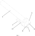
- FIG. 1 is a schematic structural diagram 1 of a part of a detection packaging structure based on a flexible tube except an outer tube according to an embodiment of the present invention.
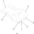
- FIG. 2 is a schematic structural diagram 2 of a part of a detection packaging structure based on a flexible tube except an outer tube according to an embodiment of the present invention.
- the detection packaging structure based on the flexible tube includes: a main circuit board 1, a detection circuit board 2, a detection component 3, an instrument tube 4, a tube cap 5, and an outer tube 7.
- the detection circuit board 2 is perpendicularly disposed on a first side surface, along a first direction, of the main circuit board 1, and the instrument tube 4 is disposed on a second side surface, along the first direction, of the main circuit board.
- the tube cap 5 is mounted on the second side surface of the main circuit board, and is connected to an end of the instrument tube.
- the first direction may be understood as a direction of a front side/reverse side, or may be understood as a direction perpendicular to a surface of the main circuit board 1.
- the detection circuit board 2 and the instrument tube 4 may be respectively disposed on surfaces on two sides of the main circuit board 1.
- the detection component 3 is disposed, along the second direction, on a first side surface of the detection circuit board 2.
- the second direction may be understood as a direction of a front side/reverse side of the detection circuit board 2, or may be understood as a direction perpendicular to a surface of the detection circuit board 2, or may be understood as a length direction of the instrument tube 4.
- the first side surface of the detection circuit board 2 may face a detection direction, so that the detection component 3 may face the detection direction.
- the first direction and the second direction may be understood as directions perpendicular to each other.
- the detection circuit board is perpendicularly disposed on the first side surface of the main circuit board, which helps rationalize space utilization, thereby facilitating reduction of an overall size of the structure.
- a first conducting material (not shown in the figure) is disposed on the first side surface, along the second direction, of the detection circuit board 2, a second conducting material 21 capable of being conducted to the first conducting material is disposed on a second side surface, along the second direction, of the detection circuit board 2, a detection conducting material 11 is disposed on the first side surface of the main circuit board 1, a wiring terminal of the detection component 3 is conductively connected to the first conducting material, one end of the detection conducting material 11 is conductively welded to the second conducting material 21, and the other end of the detection conducting material 11 is conductively connected to a cable.
- the cable is prevented from being directly welded to the detection component by using the main circuit board and the detection circuit board that are perpendicular to each other, and the conducting materials disposed on the detection circuit board.
- the detection component needs to be welded only to the first conducting material disposed on the first side surface, thereby helping enlarge a welding spot of the detection component. Therefore, based on the present invention, difficulty of welding operations is reduced, welding strength and reliability are enhanced, and welding stability in a plurality of motion statuses is satisfied.
- first side surface and the second side surface of the main circuit board 1, and the first side surface and the second side surface of the detection circuit board 2 may all be planes, and an implementation in which these side surfaces are curved surfaces or arc-shaped surfaces is not excluded in this embodiment.
- the first conducting material may be any material that can be connected and electrically conductive, and may be a metal sheet such as a copper sheet.
- the first conducting material may be disposed on the first side surface.
- a groove may be provided on the first side surface, so that the first conducting material may be disposed in the groove.
- the second conducting material 21 may be any material that can be connected and electrically conductive, and may be a metal sheet such as a copper sheet.
- the second conducting material may be disposed on the second side surface.
- a groove may be provided on the first side surface, so that the second conducting material may be disposed in the groove.
- the detection conducting material 11 may be any material that can be connected and electrically conductive, and is specifically conducted to the conducting material on the detection circuit board 2, so that signal and/or electric energy can be transmitted between the cable and the detection circuit board 2.
- the detection conducting material 11 may be a metal sheet such as a copper sheet. In an implementation, the detection conducting material 11 may extend to an outer end surface and/or an inner end surface of the main circuit board.
- the instrument tube 4 may be understood as a tube that can be equipped with a biopsy instrument, a laser instrument, or the like, and may be flexible. For details, refer to definitions of the instrument tube 4 in a controllable curved tube in the field for understanding.
- FIG. 3 is a schematic structural diagram 1 of a detection packaging structure based on a flexible tube according to an embodiment of the present invention.
- FIG. 4 is a schematic structural diagram 2 of a detection packaging structure based on a flexible tube according to an embodiment of the present invention.
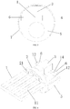
- FIG. 5 is a schematic structural diagram of an end surface of a detection packaging structure based on a flexible tube according to an embodiment of the present invention.
- the main circuit board 1, the detection circuit board 2, the detection component 3, the tube cap 5, and a part of the instrument tube 4 are all disposed in the outer tube 7, and the outer tube 7 is directly or indirectly connected to a flexible controllable curved tube.
- the outer tube 7 can be filled with glue, through which locations of the circuit boards, components, and instrument tube can be fixed, thereby implementing overall packaging of the apparatus. It may be understood that, the outer tube 7 being filled with glue means that as long as there is glue in the outer tube 7, the above description applies regardless of whether all empty spaces are filled.
- An integral insertion portion may be formed through fixing by using glue.
- FIG. 6 is a schematic structural diagram 1 of a part of a detection packaging structure based on a flexible tube except an outer tube and an instrument tube according to an embodiment of the present invention.
- FIG. 7 is a schematic structural diagram 2 of a part of a detection packaging structure based on a flexible tube except an outer tube and an instrument tube according to an embodiment of the present invention.
- FIG. 8 is a schematic structural diagram 3 of a part of a detection packaging structure based on a flexible tube except an outer tube and an instrument tube according to an embodiment of the present invention.
- the detection conducting material 11 includes at least two conductive portions, the conductive portions are along the second direction, and the at least two conductive portions are parallel to each other.
- the conductive portion is rectangular and can directly conduct the cable and the second conducting material at two ends.
- the conductive portions are lined up and arranged in parallel, which can facilitate welding between the detection conducting material 11 and the cable, and can effectively increase welding strength.
- the main circuit board 1 is provided with a mounting locating groove 15, and both the detection circuit board 2 and the tube cap 5 are mounted in the mounting locating groove 15 in an insertion manner.
- the mounting locating groove 15 is provided, so that the detection circuit board 2 and the tube cap 5 can be mounted in an insertion manner. Therefore, a radial size of an overall structure can be effectively controlled through rational utilization of space.
- the mounting locating groove 15 may be a rectangular groove.
- the tube cap 5 may be mounted on a part, distal from the cable, of the mounting locating groove 15 along the second direction.
- the detection circuit board 2 may be mounted on a part, proximal to the cable, of the mounting locating groove 15 along the second direction.
- a connecting component may be further disposed on an edge of the mounting locating groove 15.
- the connecting component may be any connecting component used for gluing, clamping, and welding, which can further facilitate stabilization of mounting and locating between the main circuit board 1 and the detection circuit board 2, and stabilization of mounting and locating between the main circuit board 1 and the tube cap 5.
- an edge of a side, distal from the main circuit board 1, of the detection circuit board 2 is arc-shaped, and the arc-shaped edge matches an inner surface of the outer tube 7, so that the detection circuit board 2 and the outer tube 7 may be assembled on the edge.
- the detection circuit board 2 may include a semicircular portion, and an insertion portion disposed on a linear edge of the semicircular portion along the first direction.
- the insertion portion may be inserted into the mounting locating groove 15, and the semicircular portion is along a third direction perpendicular to the first direction and the second direction.
- a diameter of the semicircular portion needs to be greater than a size of the insertion portion along the third direction, and the size of the insertion portion along the third direction matches a size of the mounting locating groove 15 along the third direction.
- an insertion portion is also disposed on a side, along the first direction, of the tube cap 5, and the insertion portion may be inserted into the mounting locating groove 15.
- an end surface of an end, distal from the instrument tube, of the tube cap 5 is provided with a first inclined surface
- an end surface, proximal to the tube cap, of the outer tube 7 is provided with a second inclined surface whose angle matches an angle of the first inclined surface.
- an axis of the instrument tube 4 and each of the first inclined surface and the second inclined surface can form a non-right included angle.
- the angle of the first inclined surface matching the angle of the second inclined surface means that the included angle between the first inclined surface and the axis and the included angle between the second inclined surface and the axis are the same or a difference between the included angles is less than a threshold.
- the first inclined surface may be a part of the end surface of the tube cap 5, or may be all of the end surface of the tube cap 5.
- the second inclined surface may be a part of the end surface of the outer tube 7, or may be all of the end surface of the outer tube 7.
- the foregoing inclined surfaces may be flat inclined surfaces or may be curved.
- Insertion passability of the structure or the formed insertion portion may be effectively improved by using the first inclined surface of the tube cap 5 and the second inclined surface of the outer tube 7.
- the detection component 3 may be an image acquisition component. In another optional implementation, the detection component 3 may also be any detection apparatus that detects physical and chemical properties of a liquid, a gas, or a solid, such as a liquid detection component or a gas detection component.
- the detection component 3 may be the image acquisition component. With quick development of image sensors, the smallest image sensor can now achieve 0.7 ⁇ 0.7 mm. Therefore, there is an urgent need for a packaging structure that can effectively control an external diameter and be safely and reliably packaged with lighting and low costs. However, the apparatus in this embodiment can exactly meet this demand.
- the apparatus may further include a lighting component 6.
- the lighting component 6 is disposed at an end of the main circuit board 1, which can also be understood as that the lighting component 6 is disposed at an end, proximal to the detection component 3, of the main circuit board 1.
- Both the lighting component 6 and the detection component 3 are along the second direction, and face a same direction.
- the same direction may be a detection direction, in other words, a lighting direction.
- a quantity of lighting components 6 may be two groups, and the light components 6 are distributed at the end of the main circuit board 1 along the third direction.
- the two groups of lighting components 6 may be uniformly distributed on two sides of the detection component 3 along the third direction, thereby facilitating implementation of clear and uniform lighting.
- the lighting component 6 may be any component that can emit light, or may be any component with any color and any lighting principle.
- the lighting component 6 may be an LED.
- the lighting component 6 may be monochromatic, multicolor, or allochroic.
- an opening groove 14 is provided at the end of the main circuit board 1, and the lighting component 6 is disposed in the opening groove 14.
- a shape of the opening groove 14 may match an external shape of the lighting component 6.
- opening groove 14 may facilitate stable mounting of the lighting component 6.
- a depth of the opening groove 14 along the second direction may be associated with a size of the detection component 3 along the second direction, which can help ensure that an end, distal from the detection circuit board 2, of the detection component 3 and an end, distal from the detection circuit board 2, of the lighting component 6 stay in a same reference plane.
- the reference plane is a plane perpendicular to the second direction.
- the end of the lighting component 5 may also be slightly higher or lower than the end of the detection component 3 along the second direction. The two ends conform to the matching described above, and are also located in a same reference plane described above.
- the lighting component 6 and the detection component 3 being in the same reference plane can make lighting more uniform.
- the lighting conducting material and the cable to which the lighting conducting material is connected may transmit signals or electric energy.
- a lighting conducting material is further disposed on the first side surface and/or the second side surface of the main circuit board 1, the lighting conducting material is conductively welded to the lighting component 6,at least two lighting components are connected in parallel, and the lighting conducting material is conductively connected to the cable.
- the lighting conducting material may include a first lighting conducting material 12 conductively welded to the lighting component 6, and a second lighting conducting material 13 conductively welded to the first lighting conducting material 12 and the cable along the second direction.
- the second lighting conducting material 13 may be similar to the detection conducting material 11, and includes conductive portions parallel to each other.
- the conductive portions may be lined up and arranged in parallel, which can facilitate welding between the second lighting conducting material 13 and the cable, and can effectively increase welding strength.
- a cable corresponding to lighting and a cable corresponding to detection may be different cables or may be disposed in a same cable.
- the cable may be a coaxial cable with a shielding layer.
- the shielding layer can effectively enhance welding strength and avoid occurrence of an abnormality in the cable.
- the instrument tube 4 and the tube cap 5 may be glued together, and the detection component 3 and the main circuit board 1 may also be glued together. Therefore, stability of locations between each other can be ensured, and a glue filling manner is also not excluded in this implementation.
- This embodiment further provides an in-vivo detection apparatus based on a flexible tube, including the detection packaging structure based on the flexible tube and the flexible controllable curved tube in the foregoing optional solutions, where the detection packaging structure based on the flexible tube forms an insertion portion at an end of the controllable curved tube.
- the insertion portion and the controllable curved tube may be a controllable curved tube and an insertion portion of an endoscope.
- the detection circuit board and the main circuit board that are perpendicular to each other are used, the first conducting material is disposed on the first side surface of the detection circuit board, the second conducting material capable of being conducted to the first conducting material is disposed on the second side surface, and when the detection component is connected to the first side surface of the detection circuit board, the wiring terminal of the detection component is capable of being welded to the first conducting material.
- the cable is prevented from being directly welded to the detection component by using the main circuit board and the detection circuit board that are perpendicular to each other, and the conducting materials disposed on the detection circuit board.
- the detection component needs to be welded only to the first conducting material disposed on the first side surface, thereby helping enlarge a welding spot of the detection component. Therefore, based on the present invention, difficulty of welding operations is reduced, welding strength and reliability are enhanced, and welding stability in a plurality of motion statuses is satisfied.
- the detection circuit board is perpendicularly disposed on the first side surface of the main circuit board, which helps rationalize space utilization, thereby facilitating reduction of an overall size of the structure.
Landscapes
- Health & Medical Sciences (AREA)
- Life Sciences & Earth Sciences (AREA)
- Surgery (AREA)
- Engineering & Computer Science (AREA)
- General Health & Medical Sciences (AREA)
- Molecular Biology (AREA)
- Pathology (AREA)
- Veterinary Medicine (AREA)
- Public Health (AREA)
- Biophysics (AREA)
- Biomedical Technology (AREA)
- Heart & Thoracic Surgery (AREA)
- Medical Informatics (AREA)
- Physics & Mathematics (AREA)
- Animal Behavior & Ethology (AREA)
- Optics & Photonics (AREA)
- Nuclear Medicine, Radiotherapy & Molecular Imaging (AREA)
- Radiology & Medical Imaging (AREA)
- Microelectronics & Electronic Packaging (AREA)
- Manufacturing & Machinery (AREA)
- Endoscopes (AREA)
- Instruments For Viewing The Inside Of Hollow Bodies (AREA)
- Geophysics And Detection Of Objects (AREA)
Description
- The present invention relates to the medical field, and in particular, to a detection packaging structure and an in-vivo detection apparatus that are based on a flexible tube.
- With development of science and technologies, in-vivo detection technologies based on flexible tubes have been widely applied to the medical field. An in-vivo detection apparatus based on a flexible tube can be extended into a human body to help medical personnel inspect an internal organ of the human body.
- In the related art, the in-vivo detection apparatus based on the flexible tube may include a flexible controllable curved tube and a detection component formed at an end of the controllable curved tube. A wiring terminal of the detection component may be welded to another cable through welding, to realize electrical transmission.
- However, due to a relatively small size of the detection component and a relatively small size of a cable of the detection component, it is inconvenient to weld the detection component to another cable. In addition, it is difficult to ensure a welding effect during motion. For example, it is easy for the cable of the detection component to disconnect from another cable during motion.
-
US 2017/251914 A1 also describes a compact detection packaging structure with a two circuits, a detection component, an instrument tube, a tube cap, an outer tube, a first conducting material and a detection conducting material. - The present invention provides a detection packaging structure and an in-vivo detection apparatus that are based on a flexible tube, to resolve a problem.
- According to a first aspect of the present invention, a detection packaging structure based on a flexible tube is provided, including: a main circuit board, a detection circuit board, a detection component, an instrument tube, a tube cap, and an outer tube, where
- the detection circuit board is perpendicularly disposed on a first side surface, along a first direction, of the main circuit board, the instrument tube is disposed on a second side surface, along the first direction, of the main circuit board, and the detection component is disposed, along a second direction, on a first side surface of the detection circuit board; the tube cap is mounted on the second side surface of the main circuit board, and is connected to an end of the instrument tube;
- a first conducting material is disposed on the first side surface, along the second direction, of the detection circuit board, a second conducting material capable of being conducted to the first conducting material is disposed on a second side surface, along the second direction, of the detection circuit board, a detection conducting material is disposed on the first side surface of the main circuit board, a wiring terminal of the detection component is conductively welded to the first conducting material, one end of the detection conducting material is conductively welded to the second conducting material, and the other end of the detection conducting material is conductively connected to a cable;
- the main circuit board, the detection circuit board, the detection component, the tube cap, and a part of the instrument tube are all disposed in the outer tube, and the outer tube is directly or indirectly connected to a flexible controllable curved tube; and
- the first direction is perpendicular to the second direction.
- Optionally, the detection conducting material includes at least two conductive portions, the conductive portions are along the second direction, and the at least two conductive portions are parallel to each other.
- Optionally, the main circuit board is provided with a mounting locating groove, and both the detection circuit board and the tube cap are mounted in the mounting locating groove in an insertion manner.
- Optionally, an end surface of an end, distal from the instrument tube, of the tube cap is provided with a first inclined surface, and an end surface, proximal to the tube cap, of the outer tube is provided with a second inclined surface whose angle matches an angle of the first inclined surface.
- Optionally, the detection component is an image acquisition component; a lighting component is disposed at an end of the main circuit board, and both the lighting component and the detection component are along the second direction, and face a same direction.
- Optionally, an opening groove is provided at the end of the main circuit board, and the lighting component is disposed in the opening groove.
- Optionally, a lighting conducting material is further disposed on the first side surface and/or the second side surface of the main circuit board, the lighting conducting material is conductively welded to the lighting component, at least two lighting components are connected in parallel, and the lighting conducting material is conductively connected to the cable.
- Optionally, the instrument tube and the tube cap are glued together, and the detection component and the main circuit board are glued together.
- Optionally, an edge of a side, distal from the main circuit board, of the detection circuit board is arc-shaped, and the arc-shaped edge matches an inner surface of the outer tube.
- According to a second aspect of the present invention, an in-vivo detection apparatus based on a flexible tube is provided, including the detection packaging structure based on the flexible tube and the flexible controllable curved tube in the first aspect and the optional solutions of the first aspect, where the detection packaging structure based on the flexible tube forms an insertion portion at an end of the controllable curved tube.
- For the detection packaging structure and the in-vivo detection apparatus that are based on the flexible tube provided in the present invention, the detection circuit board and the main circuit board that are perpendicular to each other are used, the first conducting material is disposed on the first side surface of the detection circuit board, the second conducting material capable of being conducted to the first conducting material is disposed on the second side surface, and when the detection component is connected to the first side surface of the detection circuit board, the wiring terminal of the detection component is capable of being welded to the first conducting material. In this way, the cable is prevented from being directly welded to the detection component by using the main circuit board and the detection circuit board that are perpendicular to each other, and the conducting materials disposed on the detection circuit board. In addition, the detection component needs to be welded only to the first conducting material disposed on the first side surface, thereby helping enlarge a welding spot of the detection component. Therefore, based on the present invention, difficulty of welding operations is reduced, welding strength and reliability are enhanced, and welding stability in a plurality of motion statuses is satisfied.
- Based on the present invention, stable mounting and use of the detection component are further ensured through assembly of the main circuit board and the detection circuit board, so that the detection component is not impacted by external force. In addition, the detection circuit board is perpendicularly disposed on the first side surface of the main circuit board, which helps rationalize space utilization, thereby facilitating reduction of an overall size of the structure.
- In an optional solution of the present invention, the cable can be conductively connected by using the at least two conductive portions parallel to each other, which can facilitate a welding operation of a cable corresponding to a sensing component and help increase welding strength.
- In an optional solution of the present invention, the mounting locating groove can help reduce a radial size after the detection circuit board and the main circuit board are mounted.
- In an optional solution of the present invention, the insertion passability of the insertion portion is effectively improved by using the first inclined surface and the second inclined surface.
- To describe the technical solutions in the embodiments of the present invention or in the prior art more clearly, accompanying drawings required to describe the embodiments or the prior art are briefly described below. It is obvious that the accompanying drawings described below are only some embodiments of the present invention. It is apparent to those of ordinary skill in the art that other drawings may be further obtained based on the accompanying drawings without inventive effort.
-
FIG. 1 is a schematic structural diagram 1 of a part of a detection packaging structure based on a flexible tube except an outer tube according to an embodiment of the present invention; -
FIG. 2 is a schematic structural diagram 2 of a part of a detection packaging structure based on a flexible tube except an outer tube according to an embodiment of the present invention; -
FIG. 3 is a schematic structural diagram 1 of a detection packaging structure based on a flexible tube according to an embodiment of the present invention; -
FIG. 4 is a schematic structural diagram 2 of a detection packaging structure based on a flexible tube according to an embodiment of the present invention; -
FIG. 5 is a schematic structural diagram of an end surface of a detection packaging structure based on a flexible tube according to an embodiment of the present invention; -
FIG. 6 is a schematic structural diagram 1 of a part of a detection packaging structure based on a flexible tube except an outer tube and an instrument tube according to an embodiment of the present invention; -
FIG. 7 is a schematic structural diagram 2 of a part of a detection packaging structure based on a flexible tube except an outer tube and an instrument tube according to an embodiment of the present invention; and -
FIG. 8 is a schematic structural diagram 3 of a part of a detection packaging structure based on a flexible tube except an outer tube and an instrument tube according to an embodiment of the present invention, where
description of reference signs:- 1-main circuit board;
- 11-detection conducting material;
- 12-first lighting conducting material;
- 13-second lighting conducting material;
- 14-opening groove;
- 15-mounting locating groove;
- 2-detection circuit board;
- 21-second conducting material;
- 3-detection component;
- 4-instrument tube;
- 5-tube cap;
- 6-lighting component; and
- 7-outer tube.
- Technical solutions in the embodiments of the present invention are clearly and completely described below with reference to accompanying drawings in the embodiments of the present invention. Apparently, the described embodiments are only some rather than all of the embodiments of the present invention.
- Terms "first", "second", "third", "fourth", and the like (if any) in the specification and claims of the present invention and the foregoing accompanying drawings are used to distinguish similar objects, but do not need to be used for describing a specific sequence or an order. It should be understood that data used in this way can be interchanged under appropriate circumstances, so that the embodiments of the present invention described herein can be implemented in an order other than those illustrated or described herein.
- The technical solutions of the present invention are described in detail below with reference to the specific embodiments. The following several embodiments may be combined with each other, and a same or similar concept or process may not be described again in some embodiments.
-
FIG. 1 is a schematic structural diagram 1 of a part of a detection packaging structure based on a flexible tube except an outer tube according to an embodiment of the present invention.FIG. 2 is a schematic structural diagram 2 of a part of a detection packaging structure based on a flexible tube except an outer tube according to an embodiment of the present invention. - Referring to
FIG. 1 , the detection packaging structure based on the flexible tube includes: amain circuit board 1, adetection circuit board 2, adetection component 3, aninstrument tube 4, atube cap 5, and anouter tube 7. - The
detection circuit board 2 is perpendicularly disposed on a first side surface, along a first direction, of themain circuit board 1, and theinstrument tube 4 is disposed on a second side surface, along the first direction, of the main circuit board. Thetube cap 5 is mounted on the second side surface of the main circuit board, and is connected to an end of the instrument tube. - The first direction may be understood as a direction of a front side/reverse side, or may be understood as a direction perpendicular to a surface of the
main circuit board 1. In this way, thedetection circuit board 2 and theinstrument tube 4 may be respectively disposed on surfaces on two sides of themain circuit board 1. - The
detection component 3 is disposed, along the second direction, on a first side surface of thedetection circuit board 2. - The second direction may be understood as a direction of a front side/reverse side of the
detection circuit board 2, or may be understood as a direction perpendicular to a surface of thedetection circuit board 2, or may be understood as a length direction of theinstrument tube 4. The first side surface of thedetection circuit board 2 may face a detection direction, so that thedetection component 3 may face the detection direction. The first direction and the second direction may be understood as directions perpendicular to each other. - It may be seen that, based on this embodiment, stable mounting and use of the detection component are further ensured through assembly of the main circuit board and the detection circuit board, so that the detection component is not impacted by external force. In addition, the detection circuit board is perpendicularly disposed on the first side surface of the main circuit board, which helps rationalize space utilization, thereby facilitating reduction of an overall size of the structure.
- A first conducting material (not shown in the figure) is disposed on the first side surface, along the second direction, of the
detection circuit board 2, asecond conducting material 21 capable of being conducted to the first conducting material is disposed on a second side surface, along the second direction, of thedetection circuit board 2, adetection conducting material 11 is disposed on the first side surface of themain circuit board 1, a wiring terminal of thedetection component 3 is conductively connected to the first conducting material, one end of thedetection conducting material 11 is conductively welded to thesecond conducting material 21, and the other end of thedetection conducting material 11 is conductively connected to a cable. - It may be seen that, in this embodiment, the cable is prevented from being directly welded to the detection component by using the main circuit board and the detection circuit board that are perpendicular to each other, and the conducting materials disposed on the detection circuit board. In addition, the detection component needs to be welded only to the first conducting material disposed on the first side surface, thereby helping enlarge a welding spot of the detection component. Therefore, based on the present invention, difficulty of welding operations is reduced, welding strength and reliability are enhanced, and welding stability in a plurality of motion statuses is satisfied.
- In addition, the first side surface and the second side surface of the
main circuit board 1, and the first side surface and the second side surface of thedetection circuit board 2 may all be planes, and an implementation in which these side surfaces are curved surfaces or arc-shaped surfaces is not excluded in this embodiment. - The first conducting material may be any material that can be connected and electrically conductive, and may be a metal sheet such as a copper sheet. In an implementation, the first conducting material may be disposed on the first side surface. In another optional implementation, a groove may be provided on the first side surface, so that the first conducting material may be disposed in the groove.
- The
second conducting material 21 may be any material that can be connected and electrically conductive, and may be a metal sheet such as a copper sheet. In an implementation, the second conducting material may be disposed on the second side surface. In another optional implementation, a groove may be provided on the first side surface, so that the second conducting material may be disposed in the groove. - The
detection conducting material 11 may be any material that can be connected and electrically conductive, and is specifically conducted to the conducting material on thedetection circuit board 2, so that signal and/or electric energy can be transmitted between the cable and thedetection circuit board 2. Thedetection conducting material 11 may be a metal sheet such as a copper sheet. In an implementation, thedetection conducting material 11 may extend to an outer end surface and/or an inner end surface of the main circuit board. - The
instrument tube 4 may be understood as a tube that can be equipped with a biopsy instrument, a laser instrument, or the like, and may be flexible. For details, refer to definitions of theinstrument tube 4 in a controllable curved tube in the field for understanding. -
FIG. 3 is a schematic structural diagram 1 of a detection packaging structure based on a flexible tube according to an embodiment of the present invention.FIG. 4 is a schematic structural diagram 2 of a detection packaging structure based on a flexible tube according to an embodiment of the present invention.FIG. 5 is a schematic structural diagram of an end surface of a detection packaging structure based on a flexible tube according to an embodiment of the present invention. - Referring to
FIG. 3 to FIG. 5 , in the embodiments, themain circuit board 1, thedetection circuit board 2, thedetection component 3, thetube cap 5, and a part of theinstrument tube 4 are all disposed in theouter tube 7, and theouter tube 7 is directly or indirectly connected to a flexible controllable curved tube. - The
outer tube 7 can be filled with glue, through which locations of the circuit boards, components, and instrument tube can be fixed, thereby implementing overall packaging of the apparatus. It may be understood that, theouter tube 7 being filled with glue means that as long as there is glue in theouter tube 7, the above description applies regardless of whether all empty spaces are filled. - An integral insertion portion may be formed through fixing by using glue.
-
FIG. 6 is a schematic structural diagram 1 of a part of a detection packaging structure based on a flexible tube except an outer tube and an instrument tube according to an embodiment of the present invention.FIG. 7 is a schematic structural diagram 2 of a part of a detection packaging structure based on a flexible tube except an outer tube and an instrument tube according to an embodiment of the present invention.FIG. 8 is a schematic structural diagram 3 of a part of a detection packaging structure based on a flexible tube except an outer tube and an instrument tube according to an embodiment of the present invention. - Referring to
FIG. 1 to FIG. 6 , in an implementation, thedetection conducting material 11 includes at least two conductive portions, the conductive portions are along the second direction, and the at least two conductive portions are parallel to each other. The conductive portion is rectangular and can directly conduct the cable and the second conducting material at two ends. - It may be seen that the conductive portions are lined up and arranged in parallel, which can facilitate welding between the
detection conducting material 11 and the cable, and can effectively increase welding strength. - In an implementation, referring to
FIG. 8 , with reference to other accompanying drawings, themain circuit board 1 is provided with amounting locating groove 15, and both thedetection circuit board 2 and thetube cap 5 are mounted in themounting locating groove 15 in an insertion manner. - The mounting locating
groove 15 is provided, so that thedetection circuit board 2 and thetube cap 5 can be mounted in an insertion manner. Therefore, a radial size of an overall structure can be effectively controlled through rational utilization of space. - The mounting locating
groove 15 may be a rectangular groove. Thetube cap 5 may be mounted on a part, distal from the cable, of the mounting locatinggroove 15 along the second direction. Thedetection circuit board 2 may be mounted on a part, proximal to the cable, of the mounting locatinggroove 15 along the second direction. - While mounting and locating are performed, a connecting component may be further disposed on an edge of the mounting locating
groove 15. For example, the connecting component may be any connecting component used for gluing, clamping, and welding, which can further facilitate stabilization of mounting and locating between themain circuit board 1 and thedetection circuit board 2, and stabilization of mounting and locating between themain circuit board 1 and thetube cap 5. - In an implementation, an edge of a side, distal from the
main circuit board 1, of thedetection circuit board 2 is arc-shaped, and the arc-shaped edge matches an inner surface of theouter tube 7, so that thedetection circuit board 2 and theouter tube 7 may be assembled on the edge. - In a specific implementation process, the
detection circuit board 2 may include a semicircular portion, and an insertion portion disposed on a linear edge of the semicircular portion along the first direction. The insertion portion may be inserted into the mounting locatinggroove 15, and the semicircular portion is along a third direction perpendicular to the first direction and the second direction. A diameter of the semicircular portion needs to be greater than a size of the insertion portion along the third direction, and the size of the insertion portion along the third direction matches a size of the mounting locatinggroove 15 along the third direction. - In a specific implementation process, an insertion portion is also disposed on a side, along the first direction, of the
tube cap 5, and the insertion portion may be inserted into the mounting locatinggroove 15. - In an implementation, referring to
FIG. 2 ,FIG. 3 ,FIG. 4 , andFIG. 7 , an end surface of an end, distal from the instrument tube, of thetube cap 5 is provided with a first inclined surface, and an end surface, proximal to the tube cap, of theouter tube 7 is provided with a second inclined surface whose angle matches an angle of the first inclined surface. - It may be understood that an axis of the
instrument tube 4 and each of the first inclined surface and the second inclined surface can form a non-right included angle. It may be understood that, the angle of the first inclined surface matching the angle of the second inclined surface means that the included angle between the first inclined surface and the axis and the included angle between the second inclined surface and the axis are the same or a difference between the included angles is less than a threshold. In addition, the first inclined surface may be a part of the end surface of thetube cap 5, or may be all of the end surface of thetube cap 5. The second inclined surface may be a part of the end surface of theouter tube 7, or may be all of the end surface of theouter tube 7. - In addition, the foregoing inclined surfaces may be flat inclined surfaces or may be curved.
- Insertion passability of the structure or the formed insertion portion may be effectively improved by using the first inclined surface of the
tube cap 5 and the second inclined surface of theouter tube 7. - In an implementation, the
detection component 3 may be an image acquisition component. In another optional implementation, thedetection component 3 may also be any detection apparatus that detects physical and chemical properties of a liquid, a gas, or a solid, such as a liquid detection component or a gas detection component. - The
detection component 3 may be the image acquisition component. With quick development of image sensors, the smallest image sensor can now achieve 0.7∗0.7 mm. Therefore, there is an urgent need for a packaging structure that can effectively control an external diameter and be safely and reliably packaged with lighting and low costs. However, the apparatus in this embodiment can exactly meet this demand. - To be suitable for implementing effective image acquisition, the apparatus may further include a
lighting component 6. Specifically, thelighting component 6 is disposed at an end of themain circuit board 1, which can also be understood as that thelighting component 6 is disposed at an end, proximal to thedetection component 3, of themain circuit board 1. Both thelighting component 6 and thedetection component 3 are along the second direction, and face a same direction. The same direction may be a detection direction, in other words, a lighting direction. - In a specific implementation process, a quantity of
lighting components 6 may be two groups, and thelight components 6 are distributed at the end of themain circuit board 1 along the third direction. In addition, the two groups oflighting components 6 may be uniformly distributed on two sides of thedetection component 3 along the third direction, thereby facilitating implementation of clear and uniform lighting. - The
lighting component 6 may be any component that can emit light, or may be any component with any color and any lighting principle. For example, thelighting component 6 may be an LED. In a specific implementation process, thelighting component 6 may be monochromatic, multicolor, or allochroic. - In an implementation, referring to
FIG. 6 andFIG. 8 , an openinggroove 14 is provided at the end of themain circuit board 1, and thelighting component 6 is disposed in theopening groove 14. A shape of the openinggroove 14 may match an external shape of thelighting component 6. - It may be seen that the opening
groove 14 may facilitate stable mounting of thelighting component 6. - In addition, a depth of the opening
groove 14 along the second direction may be associated with a size of thedetection component 3 along the second direction, which can help ensure that an end, distal from thedetection circuit board 2, of thedetection component 3 and an end, distal from thedetection circuit board 2, of thelighting component 6 stay in a same reference plane. The reference plane is a plane perpendicular to the second direction. In addition, the end of thelighting component 5 may also be slightly higher or lower than the end of thedetection component 3 along the second direction. The two ends conform to the matching described above, and are also located in a same reference plane described above. - It may be seen that the
lighting component 6 and thedetection component 3 being in the same reference plane can make lighting more uniform. - The lighting conducting material and the cable to which the lighting conducting material is connected may transmit signals or electric energy.
- In an implementation, a lighting conducting material is further disposed on the first side surface and/or the second side surface of the
main circuit board 1, the lighting conducting material is conductively welded to thelighting component 6,at least two lighting components are connected in parallel, and the lighting conducting material is conductively connected to the cable. - The lighting conducting material may include a first
lighting conducting material 12 conductively welded to thelighting component 6, and a secondlighting conducting material 13 conductively welded to the firstlighting conducting material 12 and the cable along the second direction. The secondlighting conducting material 13 may be similar to thedetection conducting material 11, and includes conductive portions parallel to each other. In addition, the conductive portions may be lined up and arranged in parallel, which can facilitate welding between the secondlighting conducting material 13 and the cable, and can effectively increase welding strength. - It may be seen that, by using the circuit boards and the conducting materials, welding strength and reliability of the detection component, the lighting component, and the cable can be effectively improved, and a short circuit risk between a welding spot and the outer tube can be reduced.
- In addition, a cable corresponding to lighting and a cable corresponding to detection may be different cables or may be disposed in a same cable.
- In a specific implementation process, the cable may be a coaxial cable with a shielding layer. The shielding layer can effectively enhance welding strength and avoid occurrence of an abnormality in the cable.
- In an implementation, the
instrument tube 4 and thetube cap 5 may be glued together, and thedetection component 3 and themain circuit board 1 may also be glued together. Therefore, stability of locations between each other can be ensured, and a glue filling manner is also not excluded in this implementation. - The structure provided in the foregoing solutions has the following positive effects: an ingenious design, less parts, rational utilization of space, simplicity, reliability, and being easy to manufacture. In addition, if this embodiment and the optional solutions of this embodiment are applied to the endoscope field, an insertion portion, with an inclined edge and a diameter of less than 3 mm, of a micro sensor endoscope can be obtained through packaging, which greatly expands an application range of micro sensors in the endoscope field.
- This embodiment further provides an in-vivo detection apparatus based on a flexible tube, including the detection packaging structure based on the flexible tube and the flexible controllable curved tube in the foregoing optional solutions, where the detection packaging structure based on the flexible tube forms an insertion portion at an end of the controllable curved tube.
- The insertion portion and the controllable curved tube may be a controllable curved tube and an insertion portion of an endoscope.
- To sum up, for the detection packaging structure and the in-vivo detection apparatus that are based on the flexible tube provided in this embodiment, the detection circuit board and the main circuit board that are perpendicular to each other are used, the first conducting material is disposed on the first side surface of the detection circuit board, the second conducting material capable of being conducted to the first conducting material is disposed on the second side surface, and when the detection component is connected to the first side surface of the detection circuit board, the wiring terminal of the detection component is capable of being welded to the first conducting material. In this way, the cable is prevented from being directly welded to the detection component by using the main circuit board and the detection circuit board that are perpendicular to each other, and the conducting materials disposed on the detection circuit board. In addition, the detection component needs to be welded only to the first conducting material disposed on the first side surface, thereby helping enlarge a welding spot of the detection component. Therefore, based on the present invention, difficulty of welding operations is reduced, welding strength and reliability are enhanced, and welding stability in a plurality of motion statuses is satisfied.
- Based on this embodiment, stable mounting and use of the detection component are further ensured through assembly of the main circuit board and the detection circuit board, so that the detection component is not impacted by external force. In addition, the detection circuit board is perpendicularly disposed on the first side surface of the main circuit board, which helps rationalize space utilization, thereby facilitating reduction of an overall size of the structure.
Claims (10)
- A detection packaging structure based on a flexible tube, comprising: a main circuit board (1), a detection circuit board (2), a detection component (3), an instrument tube (4), a tube cap (5), and an outer tube (7),wherein the detection circuit board (2) board is perpendicularly disposed on a first side surface, along a first direction, of the main circuit board (1), the instrument tube (4) is disposed on a second side surface, along the first direction, of the main circuit board (1), and the detection component (3) is disposed, along a second direction, on a first side surface of the detection circuit board (2); the tube cap (5) is mounted on the second side surface of the main circuit board (1), and is connected to an end of the instrument tube(4);a first conducting material is disposed on the first side surface, along the second direction, of the detection circuit board (2), a second conducting material (21) capable of being conducted to the first conducting material is disposed on a second side surface, along the second direction, of the detection circuit board (2), a detection conducting material (11) is disposed on the first side surface of the main circuit board (1), a wiring terminal of the detection component (3) is conductively welded to the first conducting material, one end of the detection conducting material (11) is conductively welded to the second conducting material (21), and the other end of the detection conducting material (11) is conductively connected to a cable;the main circuit board (1), the detection circuit board (2), the detection component (3), the tube cap (5), and a part of the instrument tube (4) are all disposed in the outer tube (7), and the outer tube (7) is directly or indirectly connected to a flexible controllable curved tube; andthe first direction is perpendicular to the second direction.
- The structure according to claim 1, wherein the detection conducting material comprises at least two conductive portions, the conductive portions are along the second direction, and the at least two conductive portions are parallel to each other.
- The structure according to claim 1, wherein the main circuit board is provided with a mounting locating groove, and both the detection circuit board and the tube cap are mounted in the mounting locating groove in an insertion manner.
- The structure according to claim 1, wherein an end surface of an end, distal from the instrument tube, of the tube cap is provided with a first inclined surface, and an end surface, proximal to the tube cap, of the outer tube is provided with a second inclined surface whose angle matches an angle of the first inclined surface.
- The structure according to any one of claims 1 to 4, wherein the detection component is an image acquisition component; a lighting component is disposed at an end of the main circuit board, and both the lighting component and the detection component are along the second direction, and face a same direction.
- The structure according to claim 5, wherein an opening groove is provided at the end of the main circuit board, and the lighting component is disposed in the opening groove.
- The structure according to claim 6, wherein a lighting conducting material is further disposed on the first side surface and/or the second side surface of the main circuit board, the lighting conducting material is conductively welded to the lighting component, at least two lighting components are connected in parallel, and the lighting conducting material is conductively connected to the cable.
- The structure according to any one of claims 1 to 4, wherein the instrument tube and the tube cap are glued together, and the detection component and the main circuit board are glued together.
- The structure according to any one of claims 1 to 4, wherein an edge of a side, distal from the main circuit board, of the detection circuit board is arc-shaped, and the arc-shaped edge matches an inner surface of the outer tube.
- An in-vivo detection apparatus based on a flexible tube, comprising the detection packaging structure based on the flexible tube and the flexible controllable curved tube according to any one of claims 1 to 9, wherein the detection packaging structure based on the flexible tube forms an insertion portion at an end of the controllable curved tube.
Applications Claiming Priority (2)
| Application Number | Priority Date | Filing Date | Title |
|---|---|---|---|
| CN201811570625.6A CN109700432B (en) | 2018-12-21 | 2018-12-21 | Detection packaging structure and in-vivo detection device based on flexible pipe |
| PCT/CN2019/073614 WO2020124752A1 (en) | 2018-12-21 | 2019-01-29 | Flexible tube-based detection and packaging structure and in-vivo detection device |
Publications (3)
| Publication Number | Publication Date |
|---|---|
| EP3769667A1 EP3769667A1 (en) | 2021-01-27 |
| EP3769667A4 EP3769667A4 (en) | 2021-05-19 |
| EP3769667B1 true EP3769667B1 (en) | 2021-12-22 |
Family
ID=66257206
Family Applications (1)
| Application Number | Title | Priority Date | Filing Date |
|---|---|---|---|
| EP19901183.4A Active EP3769667B1 (en) | 2018-12-21 | 2019-01-29 | Flexible tube-based detection and packaging structure and in-vivo detection device |
Country Status (7)
| Country | Link |
|---|---|
| US (1) | US12016535B2 (en) |
| EP (1) | EP3769667B1 (en) |
| JP (1) | JP7059398B2 (en) |
| CN (1) | CN109700432B (en) |
| ES (1) | ES2904507T3 (en) |
| PT (1) | PT3769667T (en) |
| WO (1) | WO2020124752A1 (en) |
Families Citing this family (3)
| Publication number | Priority date | Publication date | Assignee | Title |
|---|---|---|---|---|
| WO2021181528A1 (en) * | 2020-03-10 | 2021-09-16 | オリンパス株式会社 | Endoscope, distal end frame member of endoscope, and insertion part of endoscope |
| CN114403782A (en) * | 2022-01-28 | 2022-04-29 | 上海安清医疗器械有限公司 | Endoscope and head end device thereof |
| JP7689990B2 (en) * | 2023-06-14 | 2025-06-09 | 平河ヒューテック株式会社 | Sensor module, sensor assembly and medical device |
Family Cites Families (25)
| Publication number | Priority date | Publication date | Assignee | Title |
|---|---|---|---|---|
| US5040069A (en) * | 1989-06-16 | 1991-08-13 | Fuji Photo Optical Co., Ltd. | Electronic endoscope with a mask bump bonded to an image pick-up device |
| JPH089272A (en) * | 1994-04-22 | 1996-01-12 | Olympus Optical Co Ltd | Solid-state image pickup device for electron endoscope |
| JP2000199863A (en) * | 1999-01-07 | 2000-07-18 | Sony Corp | Solid-state imaging device |
| US6635865B1 (en) * | 2000-07-25 | 2003-10-21 | Andrew J. Soltyk | Imaging sensor microassembly having dual circuit board formed of unsymmetrical T shape |
| US7927548B2 (en) | 2005-01-27 | 2011-04-19 | Bamburgh Marsh Llc | Specimen sample collection device and test system |
| US7091731B1 (en) * | 2006-01-26 | 2006-08-15 | Agilent Technologies, Inc. | Flexible ribbon probe for peripheral leads of an electronic part's package |
| US7955255B2 (en) * | 2006-04-20 | 2011-06-07 | Boston Scientific Scimed, Inc. | Imaging assembly with transparent distal cap |
| US8792951B1 (en) | 2010-02-23 | 2014-07-29 | Vioptix, Inc. | Bone oxygenation measurement |
| CN104995907B (en) * | 2013-02-15 | 2019-05-28 | 理查德·沃尔夫有限公司 | Components for video endoscopes |
| DE102013224683A1 (en) * | 2013-12-02 | 2015-06-03 | Digital Endoscopy Gmbh | ENDOSCOPIC HEAD AND ENDOSCOPE |
| AU2015230978B2 (en) * | 2014-03-21 | 2020-01-23 | DePuy Synthes Products, Inc. | Card edge connector for an imaging sensor |
| CN107072505B (en) * | 2014-04-05 | 2021-03-12 | 手术感应设备公司 | Devices, systems, and methods for mapping of tissue oxygenation |
| JP6272745B2 (en) * | 2014-10-27 | 2018-01-31 | ソニー・オリンパスメディカルソリューションズ株式会社 | Medical device substrate and medical device |
| EP3231347B1 (en) * | 2014-12-09 | 2020-04-29 | Olympus Corporation | Endoscope |
| WO2016111075A1 (en) * | 2015-01-05 | 2016-07-14 | オリンパス株式会社 | Imaging unit, imaging module and endoscopic system |
| WO2016143179A1 (en) * | 2015-03-10 | 2016-09-15 | オリンパス株式会社 | Imaging apparatus for endoscope |
| CN204790091U (en) * | 2015-07-14 | 2015-11-18 | 深圳市源度通信有限公司 | Emission of light subassembly |
| JP6539548B2 (en) * | 2015-08-31 | 2019-07-03 | 富士フイルム株式会社 | Endoscope imaging apparatus and endoscope |
| CN205338921U (en) * | 2016-01-21 | 2016-06-29 | 史佃磊 | Multi -functional internal medicine department examination device |
| JP6617054B2 (en) * | 2016-03-03 | 2019-12-04 | 富士フイルム株式会社 | Endoscope |
| CN111315111B (en) * | 2018-12-12 | 2023-05-23 | 荣晶生物科技股份有限公司 | Endoscope device, flexible circuit board assembly and flexible circuit board thereof |
| JPWO2020121435A1 (en) * | 2018-12-12 | 2021-09-30 | オリンパス株式会社 | Endoscope tip and endoscope |
| TWM576855U (en) * | 2018-12-12 | 2019-04-21 | 榮晶生物科技股份有限公司 | Endoscope device and cable assembly thereof |
| DE102018132449B4 (en) * | 2018-12-17 | 2025-01-16 | Schölly Fiberoptic GmbH | research instrument |
| CN209808318U (en) * | 2018-12-21 | 2019-12-20 | 上海英诺伟医疗器械有限公司 | Detection packaging structure based on flexible pipe and in-vivo detection device |
-
2018
- 2018-12-21 CN CN201811570625.6A patent/CN109700432B/en active Active
-
2019
- 2019-01-29 EP EP19901183.4A patent/EP3769667B1/en active Active
- 2019-01-29 PT PT199011834T patent/PT3769667T/en unknown
- 2019-01-29 US US17/049,951 patent/US12016535B2/en active Active
- 2019-01-29 ES ES19901183T patent/ES2904507T3/en active Active
- 2019-01-29 WO PCT/CN2019/073614 patent/WO2020124752A1/en not_active Ceased
- 2019-01-29 JP JP2020558972A patent/JP7059398B2/en active Active
Also Published As
| Publication number | Publication date |
|---|---|
| JP7059398B2 (en) | 2022-04-25 |
| PT3769667T (en) | 2022-01-21 |
| US12016535B2 (en) | 2024-06-25 |
| EP3769667A1 (en) | 2021-01-27 |
| ES2904507T3 (en) | 2022-04-05 |
| WO2020124752A1 (en) | 2020-06-25 |
| CN109700432A (en) | 2019-05-03 |
| JP2021519656A (en) | 2021-08-12 |
| CN109700432B (en) | 2024-06-07 |
| EP3769667A4 (en) | 2021-05-19 |
| US20210353134A1 (en) | 2021-11-18 |
Similar Documents
| Publication | Publication Date | Title |
|---|---|---|
| JP6550318B2 (en) | Endoscope | |
| US10653306B2 (en) | Electronic circuit unit, imaging unit, and endoscope | |
| US12016535B2 (en) | Flexible tube-based detection and packaging structure and in-vivo detection device | |
| US11903565B2 (en) | Flexible catheter-based in vivo detection device and system | |
| US20200221598A1 (en) | Microelectronic device and circuit board thereof element thereof | |
| EP3053508A1 (en) | Imaging module and endoscope device | |
| US20150011891A1 (en) | Cable connection structure, ultrasonic probe, and ultrasonic endoscope system | |
| US20170251913A1 (en) | Compact image sensor module and method of assembly for image sensor modules | |
| WO2019187629A1 (en) | Endoscope | |
| WO2020181661A1 (en) | Detection package structure and in vivo detection apparatus | |
| JP5128872B2 (en) | Signal transmission member, and imaging device and endoscope using the same | |
| EP2915477A1 (en) | Electrical unit and endoscope having same mounted thereto | |
| US8853538B2 (en) | Cable connection structure and cable connection board | |
| EP2923635A1 (en) | Image pickup unit for endoscope | |
| JP6537508B2 (en) | Cable connection structure and endoscope apparatus | |
| CN209808318U (en) | Detection packaging structure based on flexible pipe and in-vivo detection device | |
| CN210204694U (en) | Detection packaging structure and in-vivo detection device | |
| WO2017115441A1 (en) | Mounting structure, image pickup device, and endoscope | |
| JP2005116400A (en) | Optical active connector | |
| CN209808294U (en) | In-vivo detection device and system based on flexible pipe | |
| JP2015029774A (en) | Board module | |
| WO2024013822A1 (en) | Endoscope, cable member, and method for producing endoscope | |
| JPH08136826A (en) | Endoscope | |
| JPH0434873A (en) | Connector | |
| JPH0621613A (en) | Structure of wiring board and coaxial cable connection |
Legal Events
| Date | Code | Title | Description |
|---|---|---|---|
| STAA | Information on the status of an ep patent application or granted ep patent |
Free format text: STATUS: THE INTERNATIONAL PUBLICATION HAS BEEN MADE |
|
| PUAI | Public reference made under article 153(3) epc to a published international application that has entered the european phase |
Free format text: ORIGINAL CODE: 0009012 |
|
| STAA | Information on the status of an ep patent application or granted ep patent |
Free format text: STATUS: REQUEST FOR EXAMINATION WAS MADE |
|
| 17P | Request for examination filed |
Effective date: 20201022 |
|
| AK | Designated contracting states |
Kind code of ref document: A1 Designated state(s): AL AT BE BG CH CY CZ DE DK EE ES FI FR GB GR HR HU IE IS IT LI LT LU LV MC MK MT NL NO PL PT RO RS SE SI SK SM TR |
|
| AX | Request for extension of the european patent |
Extension state: BA ME |
|
| A4 | Supplementary search report drawn up and despatched |
Effective date: 20210419 |
|
| RIC1 | Information provided on ipc code assigned before grant |
Ipc: A61B 5/00 20060101AFI20210413BHEP Ipc: A61B 1/05 20060101ALI20210413BHEP Ipc: A61B 1/005 20060101ALN20210413BHEP Ipc: A61B 1/06 20060101ALN20210413BHEP Ipc: A61B 1/018 20060101ALN20210413BHEP Ipc: G02B 23/24 20060101ALN20210413BHEP |
|
| RIC1 | Information provided on ipc code assigned before grant |
Ipc: G02B 23/24 20060101ALN20210802BHEP Ipc: A61B 1/018 20060101ALN20210802BHEP Ipc: A61B 1/06 20060101ALN20210802BHEP Ipc: A61B 1/005 20060101ALN20210802BHEP Ipc: A61B 1/05 20060101ALI20210802BHEP Ipc: A61B 5/00 20060101AFI20210802BHEP |
|
| GRAP | Despatch of communication of intention to grant a patent |
Free format text: ORIGINAL CODE: EPIDOSNIGR1 |
|
| STAA | Information on the status of an ep patent application or granted ep patent |
Free format text: STATUS: GRANT OF PATENT IS INTENDED |
|
| RIC1 | Information provided on ipc code assigned before grant |
Ipc: G02B 23/24 20060101ALN20210824BHEP Ipc: A61B 1/018 20060101ALN20210824BHEP Ipc: A61B 1/06 20060101ALN20210824BHEP Ipc: A61B 1/005 20060101ALN20210824BHEP Ipc: A61B 1/05 20060101ALI20210824BHEP Ipc: A61B 5/00 20060101AFI20210824BHEP |
|
| DAV | Request for validation of the european patent (deleted) | ||
| DAX | Request for extension of the european patent (deleted) | ||
| INTG | Intention to grant announced |
Effective date: 20210924 |
|
| GRAS | Grant fee paid |
Free format text: ORIGINAL CODE: EPIDOSNIGR3 |
|
| GRAA | (expected) grant |
Free format text: ORIGINAL CODE: 0009210 |
|
| STAA | Information on the status of an ep patent application or granted ep patent |
Free format text: STATUS: THE PATENT HAS BEEN GRANTED |
|
| AK | Designated contracting states |
Kind code of ref document: B1 Designated state(s): AL AT BE BG CH CY CZ DE DK EE ES FI FR GB GR HR HU IE IS IT LI LT LU LV MC MK MT NL NO PL PT RO RS SE SI SK SM TR |
|
| REG | Reference to a national code |
Ref country code: GB Ref legal event code: FG4D |
|
| REG | Reference to a national code |
Ref country code: CH Ref legal event code: EP |
|
| REG | Reference to a national code |
Ref country code: DE Ref legal event code: R096 Ref document number: 602019010333 Country of ref document: DE |
|
| REG | Reference to a national code |
Ref country code: AT Ref legal event code: REF Ref document number: 1456548 Country of ref document: AT Kind code of ref document: T Effective date: 20220115 |
|
| REG | Reference to a national code |
Ref country code: IE Ref legal event code: FG4D |
|
| REG | Reference to a national code |
Ref country code: PT Ref legal event code: SC4A Ref document number: 3769667 Country of ref document: PT Date of ref document: 20220121 Kind code of ref document: T Free format text: AVAILABILITY OF NATIONAL TRANSLATION Effective date: 20220114 |
|
| REG | Reference to a national code |
Ref country code: SE Ref legal event code: TRGR |
|
| REG | Reference to a national code |
Ref country code: NL Ref legal event code: FP |
|
| REG | Reference to a national code |
Ref country code: ES Ref legal event code: FG2A Ref document number: 2904507 Country of ref document: ES Kind code of ref document: T3 Effective date: 20220405 |
|
| REG | Reference to a national code |
Ref country code: LT Ref legal event code: MG9D |
|
| PG25 | Lapsed in a contracting state [announced via postgrant information from national office to epo] |
Ref country code: RS Free format text: LAPSE BECAUSE OF FAILURE TO SUBMIT A TRANSLATION OF THE DESCRIPTION OR TO PAY THE FEE WITHIN THE PRESCRIBED TIME-LIMIT Effective date: 20211222 Ref country code: LT Free format text: LAPSE BECAUSE OF FAILURE TO SUBMIT A TRANSLATION OF THE DESCRIPTION OR TO PAY THE FEE WITHIN THE PRESCRIBED TIME-LIMIT Effective date: 20211222 Ref country code: FI Free format text: LAPSE BECAUSE OF FAILURE TO SUBMIT A TRANSLATION OF THE DESCRIPTION OR TO PAY THE FEE WITHIN THE PRESCRIBED TIME-LIMIT Effective date: 20211222 Ref country code: BG Free format text: LAPSE BECAUSE OF FAILURE TO SUBMIT A TRANSLATION OF THE DESCRIPTION OR TO PAY THE FEE WITHIN THE PRESCRIBED TIME-LIMIT Effective date: 20220322 |
|
| PG25 | Lapsed in a contracting state [announced via postgrant information from national office to epo] |
Ref country code: NO Free format text: LAPSE BECAUSE OF FAILURE TO SUBMIT A TRANSLATION OF THE DESCRIPTION OR TO PAY THE FEE WITHIN THE PRESCRIBED TIME-LIMIT Effective date: 20220322 Ref country code: LV Free format text: LAPSE BECAUSE OF FAILURE TO SUBMIT A TRANSLATION OF THE DESCRIPTION OR TO PAY THE FEE WITHIN THE PRESCRIBED TIME-LIMIT Effective date: 20211222 Ref country code: HR Free format text: LAPSE BECAUSE OF FAILURE TO SUBMIT A TRANSLATION OF THE DESCRIPTION OR TO PAY THE FEE WITHIN THE PRESCRIBED TIME-LIMIT Effective date: 20211222 Ref country code: GR Free format text: LAPSE BECAUSE OF FAILURE TO SUBMIT A TRANSLATION OF THE DESCRIPTION OR TO PAY THE FEE WITHIN THE PRESCRIBED TIME-LIMIT Effective date: 20220323 |
|
| PG25 | Lapsed in a contracting state [announced via postgrant information from national office to epo] |
Ref country code: SM Free format text: LAPSE BECAUSE OF FAILURE TO SUBMIT A TRANSLATION OF THE DESCRIPTION OR TO PAY THE FEE WITHIN THE PRESCRIBED TIME-LIMIT Effective date: 20211222 Ref country code: SK Free format text: LAPSE BECAUSE OF FAILURE TO SUBMIT A TRANSLATION OF THE DESCRIPTION OR TO PAY THE FEE WITHIN THE PRESCRIBED TIME-LIMIT Effective date: 20211222 Ref country code: RO Free format text: LAPSE BECAUSE OF FAILURE TO SUBMIT A TRANSLATION OF THE DESCRIPTION OR TO PAY THE FEE WITHIN THE PRESCRIBED TIME-LIMIT Effective date: 20211222 Ref country code: EE Free format text: LAPSE BECAUSE OF FAILURE TO SUBMIT A TRANSLATION OF THE DESCRIPTION OR TO PAY THE FEE WITHIN THE PRESCRIBED TIME-LIMIT Effective date: 20211222 Ref country code: CZ Free format text: LAPSE BECAUSE OF FAILURE TO SUBMIT A TRANSLATION OF THE DESCRIPTION OR TO PAY THE FEE WITHIN THE PRESCRIBED TIME-LIMIT Effective date: 20211222 |
|
| PG25 | Lapsed in a contracting state [announced via postgrant information from national office to epo] |
Ref country code: PL Free format text: LAPSE BECAUSE OF FAILURE TO SUBMIT A TRANSLATION OF THE DESCRIPTION OR TO PAY THE FEE WITHIN THE PRESCRIBED TIME-LIMIT Effective date: 20211222 |
|
| REG | Reference to a national code |
Ref country code: CH Ref legal event code: PL |
|
| REG | Reference to a national code |
Ref country code: DE Ref legal event code: R097 Ref document number: 602019010333 Country of ref document: DE |
|
| PG25 | Lapsed in a contracting state [announced via postgrant information from national office to epo] |
Ref country code: MC Free format text: LAPSE BECAUSE OF FAILURE TO SUBMIT A TRANSLATION OF THE DESCRIPTION OR TO PAY THE FEE WITHIN THE PRESCRIBED TIME-LIMIT Effective date: 20211222 Ref country code: IS Free format text: LAPSE BECAUSE OF FAILURE TO SUBMIT A TRANSLATION OF THE DESCRIPTION OR TO PAY THE FEE WITHIN THE PRESCRIBED TIME-LIMIT Effective date: 20220422 |
|
| PLBE | No opposition filed within time limit |
Free format text: ORIGINAL CODE: 0009261 |
|
| STAA | Information on the status of an ep patent application or granted ep patent |
Free format text: STATUS: NO OPPOSITION FILED WITHIN TIME LIMIT |
|
| PG25 | Lapsed in a contracting state [announced via postgrant information from national office to epo] |
Ref country code: LU Free format text: LAPSE BECAUSE OF NON-PAYMENT OF DUE FEES Effective date: 20220129 Ref country code: DK Free format text: LAPSE BECAUSE OF FAILURE TO SUBMIT A TRANSLATION OF THE DESCRIPTION OR TO PAY THE FEE WITHIN THE PRESCRIBED TIME-LIMIT Effective date: 20211222 Ref country code: AL Free format text: LAPSE BECAUSE OF FAILURE TO SUBMIT A TRANSLATION OF THE DESCRIPTION OR TO PAY THE FEE WITHIN THE PRESCRIBED TIME-LIMIT Effective date: 20211222 |
|
| 26N | No opposition filed |
Effective date: 20220923 |
|
| PG25 | Lapsed in a contracting state [announced via postgrant information from national office to epo] |
Ref country code: LI Free format text: LAPSE BECAUSE OF NON-PAYMENT OF DUE FEES Effective date: 20220131 Ref country code: CH Free format text: LAPSE BECAUSE OF NON-PAYMENT OF DUE FEES Effective date: 20220131 |
|
| PG25 | Lapsed in a contracting state [announced via postgrant information from national office to epo] |
Ref country code: IE Free format text: LAPSE BECAUSE OF NON-PAYMENT OF DUE FEES Effective date: 20220129 |
|
| PG25 | Lapsed in a contracting state [announced via postgrant information from national office to epo] |
Ref country code: SI Free format text: LAPSE BECAUSE OF FAILURE TO SUBMIT A TRANSLATION OF THE DESCRIPTION OR TO PAY THE FEE WITHIN THE PRESCRIBED TIME-LIMIT Effective date: 20211222 |
|
| REG | Reference to a national code |
Ref country code: AT Ref legal event code: UEP Ref document number: 1456548 Country of ref document: AT Kind code of ref document: T Effective date: 20211222 |
|
| PG25 | Lapsed in a contracting state [announced via postgrant information from national office to epo] |
Ref country code: MK Free format text: LAPSE BECAUSE OF FAILURE TO SUBMIT A TRANSLATION OF THE DESCRIPTION OR TO PAY THE FEE WITHIN THE PRESCRIBED TIME-LIMIT Effective date: 20211222 Ref country code: CY Free format text: LAPSE BECAUSE OF FAILURE TO SUBMIT A TRANSLATION OF THE DESCRIPTION OR TO PAY THE FEE WITHIN THE PRESCRIBED TIME-LIMIT Effective date: 20211222 |
|
| PG25 | Lapsed in a contracting state [announced via postgrant information from national office to epo] |
Ref country code: HU Free format text: LAPSE BECAUSE OF FAILURE TO SUBMIT A TRANSLATION OF THE DESCRIPTION OR TO PAY THE FEE WITHIN THE PRESCRIBED TIME-LIMIT; INVALID AB INITIO Effective date: 20190129 |
|
| PG25 | Lapsed in a contracting state [announced via postgrant information from national office to epo] |
Ref country code: MT Free format text: LAPSE BECAUSE OF FAILURE TO SUBMIT A TRANSLATION OF THE DESCRIPTION OR TO PAY THE FEE WITHIN THE PRESCRIBED TIME-LIMIT Effective date: 20211222 |
|
| PG25 | Lapsed in a contracting state [announced via postgrant information from national office to epo] |
Ref country code: TR Free format text: LAPSE BECAUSE OF FAILURE TO SUBMIT A TRANSLATION OF THE DESCRIPTION OR TO PAY THE FEE WITHIN THE PRESCRIBED TIME-LIMIT Effective date: 20211222 |
|
| PGFP | Annual fee paid to national office [announced via postgrant information from national office to epo] |
Ref country code: GB Payment date: 20251215 Year of fee payment: 8 |
|
| PGFP | Annual fee paid to national office [announced via postgrant information from national office to epo] |
Ref country code: PT Payment date: 20251211 Year of fee payment: 8 |
|
| PGFP | Annual fee paid to national office [announced via postgrant information from national office to epo] |
Ref country code: NL Payment date: 20251215 Year of fee payment: 8 Ref country code: FR Payment date: 20251215 Year of fee payment: 8 |
|
| PGFP | Annual fee paid to national office [announced via postgrant information from national office to epo] |
Ref country code: BE Payment date: 20251215 Year of fee payment: 8 |
|
| PGFP | Annual fee paid to national office [announced via postgrant information from national office to epo] |
Ref country code: SE Payment date: 20251211 Year of fee payment: 8 |
|
| PGFP | Annual fee paid to national office [announced via postgrant information from national office to epo] |
Ref country code: ES Payment date: 20260217 Year of fee payment: 8 |
|
| PGFP | Annual fee paid to national office [announced via postgrant information from national office to epo] |
Ref country code: DE Payment date: 20260120 Year of fee payment: 8 |
|
| PGFP | Annual fee paid to national office [announced via postgrant information from national office to epo] |
Ref country code: AT Payment date: 20260119 Year of fee payment: 8 |
|
| PGFP | Annual fee paid to national office [announced via postgrant information from national office to epo] |
Ref country code: IT Payment date: 20260130 Year of fee payment: 8 |