EP3769054B1 - Verfahren zum betrieb eines containers - Google Patents
Verfahren zum betrieb eines containers Download PDFInfo
- Publication number
- EP3769054B1 EP3769054B1 EP19709880.9A EP19709880A EP3769054B1 EP 3769054 B1 EP3769054 B1 EP 3769054B1 EP 19709880 A EP19709880 A EP 19709880A EP 3769054 B1 EP3769054 B1 EP 3769054B1
- Authority
- EP
- European Patent Office
- Prior art keywords
- container
- pressure
- filling material
- protective gas
- medium channel
- Prior art date
- Legal status (The legal status is an assumption and is not a legal conclusion. Google has not performed a legal analysis and makes no representation as to the accuracy of the status listed.)
- Active
Links
Images





Classifications
-
- G—PHYSICS
- G01—MEASURING; TESTING
- G01F—MEASURING VOLUME, VOLUME FLOW, MASS FLOW OR LIQUID LEVEL; METERING BY VOLUME
- G01F23/00—Indicating or measuring liquid level or level of fluent solid material, e.g. indicating in terms of volume or indicating by means of an alarm
- G01F23/14—Indicating or measuring liquid level or level of fluent solid material, e.g. indicating in terms of volume or indicating by means of an alarm by measurement of pressure
-
- B—PERFORMING OPERATIONS; TRANSPORTING
- B65—CONVEYING; PACKING; STORING; HANDLING THIN OR FILAMENTARY MATERIAL
- B65D—CONTAINERS FOR STORAGE OR TRANSPORT OF ARTICLES OR MATERIALS, e.g. BAGS, BARRELS, BOTTLES, BOXES, CANS, CARTONS, CRATES, DRUMS, JARS, TANKS, HOPPERS, FORWARDING CONTAINERS; ACCESSORIES, CLOSURES, OR FITTINGS THEREFOR; PACKAGING ELEMENTS; PACKAGES
- B65D81/00—Containers, packaging elements, or packages, for contents presenting particular transport or storage problems, or adapted to be used for non-packaging purposes after removal of contents
- B65D81/18—Containers, packaging elements, or packages, for contents presenting particular transport or storage problems, or adapted to be used for non-packaging purposes after removal of contents providing specific environment for contents, e.g. temperature above or below ambient
-
- B—PERFORMING OPERATIONS; TRANSPORTING
- B65—CONVEYING; PACKING; STORING; HANDLING THIN OR FILAMENTARY MATERIAL
- B65D—CONTAINERS FOR STORAGE OR TRANSPORT OF ARTICLES OR MATERIALS, e.g. BAGS, BARRELS, BOTTLES, BOXES, CANS, CARTONS, CRATES, DRUMS, JARS, TANKS, HOPPERS, FORWARDING CONTAINERS; ACCESSORIES, CLOSURES, OR FITTINGS THEREFOR; PACKAGING ELEMENTS; PACKAGES
- B65D88/00—Large containers
- B65D88/26—Hoppers, i.e. containers having funnel-shaped discharge sections
-
- B—PERFORMING OPERATIONS; TRANSPORTING
- B65—CONVEYING; PACKING; STORING; HANDLING THIN OR FILAMENTARY MATERIAL
- B65D—CONTAINERS FOR STORAGE OR TRANSPORT OF ARTICLES OR MATERIALS, e.g. BAGS, BARRELS, BOTTLES, BOXES, CANS, CARTONS, CRATES, DRUMS, JARS, TANKS, HOPPERS, FORWARDING CONTAINERS; ACCESSORIES, CLOSURES, OR FITTINGS THEREFOR; PACKAGING ELEMENTS; PACKAGES
- B65D90/00—Component parts, details or accessories for large containers
- B65D90/48—Arrangements of indicating or measuring devices
-
- B—PERFORMING OPERATIONS; TRANSPORTING
- B67—OPENING, CLOSING OR CLEANING BOTTLES, JARS OR SIMILAR CONTAINERS; LIQUID HANDLING
- B67D—DISPENSING, DELIVERING OR TRANSFERRING LIQUIDS, NOT OTHERWISE PROVIDED FOR
- B67D3/00—Apparatus or devices for controlling flow of liquids under gravity from storage containers for dispensing purposes
- B67D3/0058—Details
- B67D3/0061—Details of liquid containers, e.g. filling, emptying, closing or opening means
-
- G—PHYSICS
- G01—MEASURING; TESTING
- G01F—MEASURING VOLUME, VOLUME FLOW, MASS FLOW OR LIQUID LEVEL; METERING BY VOLUME
- G01F22/00—Methods or apparatus for measuring volume of fluids or fluent solid material, not otherwise provided for
- G01F22/02—Methods or apparatus for measuring volume of fluids or fluent solid material, not otherwise provided for involving measurement of pressure
-
- G—PHYSICS
- G01—MEASURING; TESTING
- G01F—MEASURING VOLUME, VOLUME FLOW, MASS FLOW OR LIQUID LEVEL; METERING BY VOLUME
- G01F23/00—Indicating or measuring liquid level or level of fluent solid material, e.g. indicating in terms of volume or indicating by means of an alarm
- G01F23/14—Indicating or measuring liquid level or level of fluent solid material, e.g. indicating in terms of volume or indicating by means of an alarm by measurement of pressure
- G01F23/18—Indicating, recording or alarm devices actuated electrically
-
- B—PERFORMING OPERATIONS; TRANSPORTING
- B65—CONVEYING; PACKING; STORING; HANDLING THIN OR FILAMENTARY MATERIAL
- B65D—CONTAINERS FOR STORAGE OR TRANSPORT OF ARTICLES OR MATERIALS, e.g. BAGS, BARRELS, BOTTLES, BOXES, CANS, CARTONS, CRATES, DRUMS, JARS, TANKS, HOPPERS, FORWARDING CONTAINERS; ACCESSORIES, CLOSURES, OR FITTINGS THEREFOR; PACKAGING ELEMENTS; PACKAGES
- B65D2588/00—Large container
- B65D2588/74—Large container having means for heating, cooling, aerating or other conditioning of contents
- B65D2588/743—Large container having means for heating, cooling, aerating or other conditioning of contents blowing or injecting heating, cooling or other conditioning fluid inside the container
- B65D2588/746—Large container having means for heating, cooling, aerating or other conditioning of contents blowing or injecting heating, cooling or other conditioning fluid inside the container with additional treatment function
-
- B—PERFORMING OPERATIONS; TRANSPORTING
- B65—CONVEYING; PACKING; STORING; HANDLING THIN OR FILAMENTARY MATERIAL
- B65D—CONTAINERS FOR STORAGE OR TRANSPORT OF ARTICLES OR MATERIALS, e.g. BAGS, BARRELS, BOTTLES, BOXES, CANS, CARTONS, CRATES, DRUMS, JARS, TANKS, HOPPERS, FORWARDING CONTAINERS; ACCESSORIES, CLOSURES, OR FITTINGS THEREFOR; PACKAGING ELEMENTS; PACKAGES
- B65D2590/00—Component parts, details or accessories for large containers
- B65D2590/0083—Computer or electronic system, e.g. GPS systems
-
- G—PHYSICS
- G01—MEASURING; TESTING
- G01F—MEASURING VOLUME, VOLUME FLOW, MASS FLOW OR LIQUID LEVEL; METERING BY VOLUME
- G01F1/00—Measuring the volume flow or mass flow of fluid or fluent solid material wherein the fluid passes through a meter in a continuous flow
- G01F1/007—Measuring the volume flow or mass flow of fluid or fluent solid material wherein the fluid passes through a meter in a continuous flow by measuring the level variations of storage tanks relative to the time
Definitions
- the present application relates to a method according to the preamble of claim 1.
- a container the operation of which is the subject of the method, can be used in particular to store an aqueous, free-flowing filling material. Mention should be made here of so-called fruit preparations, for example, which are bottled by a manufacturer and then sold to customers.
- the container includes in particular a frame and a container, the container being storable by means of the frame at a distance above an underground. In this way the container is accessible from its underside.
- the container has at least one opening on said underside, by means of which the container can be loaded with filling material or filling material can be removed from the container.
- the container also has at least one gas connection, by means of which a protective gas line can be connected to the container.
- Such a protective gas line makes it possible to feed a protective gas, for example carbon dioxide, to the container. In this way it is ensured that, in addition to the filling material itself, an interior space of the container is filled exclusively with the protective gas. This ensures that the filling material in the container does not deteriorate through contact with the ambient air.
- a protective gas for example carbon dioxide
- the inert gas line is usually connected to the gas connection of the container before a sampling device is connected to the opening of the container.
- the consequence of this is that the inert gas line is in any case already connected at the moment the filling material is removed from the container and inert gas can flow into the interior of the container at any time. Accordingly, it is customary to only remove the inert gas line from the container when the filling material has been removed. In particular, it is conceivable to always separate the extraction device from the opening first, before the protective gas line is removed from the gas connection.
- the container is preferably made of stainless steel, so that it can be used as often as desired, that is to say in particular it can be loaded and unloaded. If the filling material has a comparatively high viscosity, it can be useful to pump the filling material out of the container by means of a pump in order to remove it. In the course of removing the Filling material from the interior of the container to ensure a sufficient flow of protective gas, it is also advantageous if the protective gas line is connected to a pressure source that provides the protective gas under a certain pressure. In this way it is ensured that no foreign gas, in particular no ambient air, unintentionally flows into the container.
- the U.S. 2018/0052030 A1 discloses a fluid level measuring arrangement comprising a container with an inlet and an outlet for the filling material arranged on the underside.
- a plurality of flow lines extend from a medium supply to the container, each flow line opening out at a different level inside the container.
- a first flow line opens at a lowest level
- a second flow line opens at an intermediate level
- a third flow line opens at a highest level.
- a pressure transducer is positioned in each of the flow lines to measure the pressure within each flow line. When the fluid level in the container exceeds the lowest level, thereby covering the mouth of the first flow line, the pressure transducer detects a sharp increase in pressure compared to the outlet pressure in the flow line. This increase in pressure indicates the liquid level in the container.
- the pressure transducers in the three flow lines measure a constant pressure until the level has exceeded the mouth of the lowest, middle or highest flow line. The sensed levels are used to fully or partially open or close the outlet and/or inlet to
- the CN 205 615 969 U discloses a tank for holding methanol having an inlet tube and an outlet tube.
- a first gas inlet pipe, a second gas inlet pipe and a third gas inlet pipe for the supply of nitrogen are arranged at the top of the tank, the first gas inlet pipe opening at the top, the second gas inlet pipe at the bottom and the third gas inlet pipe opening in the middle of the tank.
- the first air inlet pipe is equipped with a gauge that can measure the pressure at the liquid surface.
- the second gas inlet tube directs the nitrogen to the bottom of the tank.
- a gauge is placed on the second gas inlet tube to measure the pressure difference between the bottom of the liquid and the liquid surface. The liquid height is calculated from the pressure difference.
- Another gauge on the third gas inlet tube measures the pressure difference between the second gas inlet tube and the third gas inlet tube to determine the density of the liquid.
- the present application is based on the object of providing a method by means of which the filling level of a respective container can be determined more easily in comparison to the prior art.
- the method provides that before the filling material is removed from the container, an inert gas line is connected to the gas connection and pressurized. A corresponding procedure has already been explained at the outset. Furthermore, a removal device is connected to the opening of the container, so that filling material can be removed from the container by means of the removal device. In principle, the connection of the inert gas line and the connection of the extraction device to the container are not subject to any chronological order. The only thing that matters is that the actual removal of the filling material, the protective gas line is connected to the container and pressurized, so that protective gas can be tracked and thus a volume released in the container due to the removal of the filling material can be filled.
- the “medium channel” can refer to any line through which the protective gas can flow into the container.
- the medium channel can be formed directly on the protective gas line or on or in the container itself.
- the medium channel is formed on an adapter element that is connected to the container in a force-transmitting manner.
- the inert gas line can be connected to the adapter element so that the inert gas provided by means of the inert gas line can flow through the adapter element or a medium channel thereof to the gas connection of the container and finally into the interior of the container.
- the method according to the invention only requires that at least one medium channel, through which the protective gas flows into the container, be equipped with a pressure sensor, so that a pressure of the protective gas in the medium channel can be detected at least indirectly by means of the pressure sensor.
- the "pressure” does not necessarily have to designate an overall pressure of the protective gas. Instead, it is also possible that the detected pressure only describes a partial pressure of the protective gas, for example a dynamic pressure or a static pressure of the protective gas.
- the dynamic pressure of the protective gas is determined by its flow rate within the medium channel.
- the static pressure within the medium channel can be detected, for example, by means of a stub line which extends obliquely, preferably perpendicularly, to a longitudinal axis of the medium duct and is connected to a medium duct, with the pressure sensor being arranged at an end of the stub line remote from the medium channel.
- a flow of protective gas through the medium channel is oriented perpendicularly to the stub line, so that a pressure detected by means of the pressure sensor arranged at the end of the stub line is free from a proportion of the dynamic pressure in the overall pressure of the protective gas. Instead, only the static pressure of the protective gas is detected by means of such a pressure sensor.
- the medium channel with a pitot tube, which has a section that extends in the direction of the medium channel parallel to the longitudinal axis.
- a pitot tube By means of an opening cross-section, such a pitot tube is suitable for receiving protective gas flowing through the medium channel, with a pressure sensor arranged at an end of the pitot tube facing away from the medium channel being able to record a total pressure of the protective gas, i.e. the sum of a static and a dynamic pressure of the protective gas.
- a total pressure of the protective gas i.e. the sum of a static and a dynamic pressure of the protective gas.
- the dynamic pressure of the protective gas can be deduced by means of subtraction.
- a combined detection of total pressure and static pressure is possible, for example, using a Prandtl tube, the use of which is equally conceivable here.
- Alternative arrangements of a pressure sensor on or in a medium channel are of course also conceivable.
- the method according to the invention has many advantages.
- it is possible to monitor a large number of containers in a decentralized manner and without any additional external aids, and to track the filling level of each individual container individually. All that is required for this is to arrange at least one pressure sensor in or on a medium channel of the container and to process data recorded by the pressure sensor.
- a respective container can be equipped with such a pressure sensor in a particularly simple manner by means of an adapter element that can be used on the gas connection, as will be explained separately below.
- a statement can also be made as a function of the pressure conditions as to how large the volume flow of the protective gas flowing into the container and consequently also the mass flow of the filling material removed from the container are.
- the "removal speed" relating to the filling material can be taken into account as an additional parameter.
- the volume flow of the inert gas flowing in is proportional to the mass flow of the filling material removed from the container, so that the filling level of the container can be precisely determined quantitatively.
- the fill level can be estimated with sufficient accuracy using the determined removal duration, assuming typical values for the mass flow during removal for a specific filling material.
- the initial removal of filling material from the completely filled container and the complete emptying of the container can be determined at least reliably by evaluating the pressure curve. A qualitative filling level control is therefore always possible with the pressure sensor.
- the protective gas is accelerated in the medium channel, in particular by means of a constriction arranged in the medium channel.
- a constriction is defined in that a cross section of the medium channel in the area of the constriction is smaller than a cross section of the medium channel outside of the constriction.
- the acceleration of the shielding gas in the area of the constriction leads to a local increase in the dynamic pressure of the shielding gas, while the static pressure decreases accordingly. This applies at least to those cases in which a total pressure of the protective gas provided by a pressure source is at least essentially, in particular completely, constant.
- the area-wise acceleration of the protective gas within the medium channel makes it easier in particular to determine changes in a volume flow that flows through the medium channel into the interior of the container.
- the collection of data relating to such a change is advantageous insofar as such data can be used to indirectly determine the mass flow with which filling material is removed from the container. This is based on the consideration that the quicker the removal of filling material from the container, the quicker the subsequent flow of protective gas through the medium channel will be.
- the survey of the pressure conditions in the medium channel for example according to the Venturi principle or by means of a pitot tube, can therefore help to make a corresponding statement.
- the recorded static and dynamic pressure allows the calculation of the flow velocity of the protective gas in a flow cross-section using Bernoulli's law.
- the calculation of the mass flow of the inflowing protective gas then results from the product of the density of the protective gas, the calculated flow speed and the flow cross-section.
- it is conceivable to directly and separately determine a mass flow of the filling material exiting the container through the opening it being possible, for example, to arrange a corresponding flow sensor at the opening of the container.
- data recorded by means of the pressure sensor are stored at least temporarily by means of a data logger.
- a data logger it is conceivable to store the recorded data at least until the container has been completely emptied.
- the data recorded by means of the pressure sensor are processed by means of an evaluation unit.
- the latter can, for example, use a stored algorithm to determine changes in the pressure present in the medium channel and, based on this, to determine the times at which the removal of filling material from the container begins and/or ends.
- a transmitter can, for example, use the normal cellular network to transmit data. In this way, it is possible for an authorized person to call up and view the relevant data and make individual decisions based on this.
- the container used in the method includes at least one sensor device that has an adapter element.
- This adapter element is suitable for being connected to the gas connection of the container, preferably in a detachable manner, so that the sensor device is connected to the container.
- the adapter element comprises at least one gas connection piece and at least one medium channel, with the gas connection piece being suitable for accommodating a protective gas line, so that protective gas, starting from the protective gas line, through the gas connection piece and through the medium channel of the adapter element, to the gas connection of the container and finally into the interior of the container is conductive.
- the sensor device comprises at least one pressure sensor which interacts at least indirectly with the medium channel.
- the at least one pressure sensor can be used to record data relating to the pressure of the protective gas in the medium channel. As already explained above, this pressure can be either a total pressure of the protective gas or partial pressures thereof, for example a dynamic pressure and/or a static pressure.
- the method according to the invention can be carried out particularly easily using the container.
- the at least one pressure sensor can be used to collect data relating to a pressure within the medium channel in a particularly simple manner, from which, in the manner described, conclusions can be drawn about a removed quantity of filling material and therefore about a filling level of a respective container with filling material.
- the medium channel of the adapter element has at least one constriction, at which a cross section of the medium channel is reduced compared to a cross section of the medium channel outside of the constriction.
- the constriction is advantageously integrated into the medium channel in such a way that the cross section of the medium channel is widened on both sides of the constriction.
- the medium channel is advantageously designed in such a way that gas flowing through the medium channel is accelerated in the region of the constriction and is then decelerated after leaving the constriction due to the particularly conical widening of the medium channel.
- the dynamic pressure thereof is increased locally within the medium channel and the static pressure is correspondingly reduced as long as the total pressure of the gas, which is provided, for example, from a pressurized gas cylinder, remains constant.
- the sensor device has at least one branch line which interacts in terms of flow with the medium channel of the adapter element.
- a longitudinal axis of the stub is preferably perpendicular to a Oriented along the longitudinal axis of the medium channel so that the stub line meets the medium channel perpendicularly.
- An embodiment in which the branch line meets the medium channel in the area of a constriction mentioned above is particularly preferred.
- Such a configuration of the sensor device enables the measurement of a change in the static pressure within the medium channel, which results from a flow rate of the gas flowing through the medium channel. This is based on the consideration that the higher the flow velocity of the gas in the area of the constriction, the higher the dynamic pressure and, conversely, the lower the static pressure of the gas in the medium channel, insofar as a total pressure of the gas is generated by a pressure source is provided is constant.
- the pressure in the branch line also changes, which, due to its preferred perpendicular orientation to the medium channel, is exclusively subjected to the static pressure of the gas, with this change being detectable by means of the pressure sensor.
- the inert gas is flowing through the medium channel and consequently that filling material is evidently being removed from the vessel of the container. Otherwise the shielding gas would not flow into the container, but possibly only the static pressure would increase, depending on the pressure level of the source of the shielding gas.
- the combination of constriction, branch line and pressure sensor enables the flow conditions of a protective gas to be monitored by the sensor device.
- a pressure curve which was detected by the pressure sensor and then recorded, can have characteristic deflections, especially at moments when a pump for removing the filling material is activated and deactivated, by means of their interpretation in the manner described above, a statement about a removal duration and from it resulting in a removed amount of the filling is possible.
- the pressure curve can show a sudden drop at the moment the pump is activated, which can be attributed to a flow of protective gas within the medium channel. This starts because a vacant volume in the interior of the container is "replenished" with protective gas, which flows through the gas connection of the container - and thus previously through the medium channel of the sensor device - into the interior.
- the static pressure drops in the area of the constriction due to the increase in dynamic pressure, which is registered as a pressure drop by the pressure sensor in the branch line connected to the constriction.
- the static pressure in the branch line increases again when the removal of filling material from the container is complete, so that the point in time at which the removal was completed can be determined.
- FIG. 1 to 9 An embodiment in the Figures 1 to 9 is shown comprises a container 1, which comprises a container 4 and a frame 2 .
- the frame 2 in turn comprises a plurality of legs 42, by means of which the container 1 stands up on a base 3 .
- the container 4 is mounted at a distance from the base 3 by means of the frame 2 in such a way that an underside 6 of the container 4 is accessible from below.
- a lowest point 43 of the container 4 is at a distance 5 from the base 3. Said lowest point 43 interacts with an opening 7 through which an interior 8 of the container 4 can be loaded with filling material or said filling material from the interior 8 can be removed.
- the container 4 interacts with a connecting pipe 30 that has a 90° angle, so that a cross section of the opening 7 is oriented vertically.
- the opening 7 interacts here with a connecting piece, so that a filling material hose can be coupled to the opening 7 , by means of which filling material can be removed from the container 4 or, conversely, filling material can be filled into the container 4 .
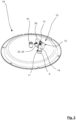
- the container 1 On an upper side 18 the container 1 has a cover 19 on which a gas connection 9 and a pressure relief valve 31 are formed.
- This gas connection 9 is used to interact with a protective gas line, not shown in the figures.
- a protective gas line makes it possible to supply a protective gas, for example carbon dioxide, to the interior 8 of the container 4 .
- a protective gas is important in order to fill up a free volume that is available in the container 4 and is not filled with a particular product. In particular, it is often to be avoided that the filling material comes into contact with oxygen, whereupon the filling material would oxidize. The inert gas prevents such reactions and thus contributes to a long shelf life of the filling within the container 4 .
- the protective gas line is typically connected to a pressure source, by means of which the respective protective gas is made available under pressure. In this way, it is ensured that in the course of removing the filling material from the container 4 , protective gas immediately flows into the volume released in the container 4 .
- the gas connection 9 interacts with a gas connector 17 , which is suitable here for interacting with a quick-release fastener 32 of the protective gas line.
- a gas connector 17 which is suitable here for interacting with a quick-release fastener 32 of the protective gas line.
- the container 1 includes a sensor device 10 which includes an adapter element 11 and a telemetry module 12 .
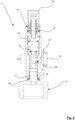
- the adapter element 11 comprises a medium channel 14 and a gas connection piece 13.
- the adapter element 11 has a connection section 44 which is designed in a complementary manner to the gas connection piece 17 of the gas connection 9 of the container 4 .
- the sensor device 10 can be fixed to the gas connection piece 17 , the sensor device 10 being able to be plugged or plugged onto the gas connection piece 17 to a certain extent.
- the gas connector 17 has a sealing ring 34 by means of which the adapter element 11 can be sealed against the gas connection 9 .
- connection section 44 and the gas connection piece 17 are in principle identical to that by means of which a protective gas line can be connected to the gas connection piece 17 .
- a protective gas line can be connected to the gas connection piece 17 .
- the adapter element 11 has the gas connector 13 , which interacts with a quick-release fastener 32 in the example shown.
- the quick-release fastener 32 is sealed off from the gas connection piece 13 of the adapter element 11 by means of a sealing ring 33 .
- the gas connection piece 13 is designed here in a particularly advantageous manner to be compatible with the gas connection piece 17 of the container 4 .
- the gas connection piece 13 of the adapter element 11 reproduces the gas connection piece 17 of the gas connection 9 at least substantially, preferably completely, identically.
- a respective protective gas line can be connected directly to the gas connection piece 13 of the adapter element 11 instead of to the gas connection piece 17 of the gas connection 9 without any need for adaptation or modification.
- the container 1 can continue to be used without any conversion, although the actual gas connection 9 of the container 1 is now used to fix the sensor device 10 to the container 1 .
- the gas nozzle 13 of the adapter element 11 interacts fluidically with its medium channel 14 , so that after connecting a protective gas line to the Gas connector 13 (here using the quick-release fastener 32 ), the respective protective gas can flow directly through the medium channel 14 to the gas connection 9 of the container 4 and finally into the interior 8 of the container 4 .
- the telemetry module 12 of the sensor device 10 comprises a plurality of sensors 15 and a transmitter 16.
- the telemetry module 12 has a geoposition sensor 41, an acceleration sensor 25, a temperature sensor 28, a data logger 26 and an evaluation unit 27 .
- These components of the telemetry module 12 are housed together in a housing 29 which protects said components from external influences, in particular moisture and dirt.
- the sensors 15 are suitable for acquiring data relating to at least one status parameter of the container 1 and/or one status parameter of the filling material stored in the container 1 .
- the said data can be sent by means of the transmitter 16 , possibly after intermediate storage in the data logger 26 and, if necessary, processing by means of the evaluation unit 27 , so that the said data can be called up wirelessly from a distance.
- the recorded data can be stored by means of the data logger 26 , so that not only current data sets can be called up, but in particular a history can also be evaluated.
- the at least one acceleration sensor 25 can also be used to detect acceleration states of the container 1 , with strong deflections being able to indicate an accident, for example.
- the medium channel 14 of the adapter element 11 includes a constriction 20 in the area of which a cross section 21 of the medium channel 14 is reduced compared to a cross section 22 outside of the constriction 20 .
- the constriction 20 is designed in such a way that the medium channel 14 widens on both sides of the constriction 20 .
- the medium channel 14 is designed in the area of the constriction 20 in the form of a Venturi nozzle.
- the reduction in the cross section of the medium channel 14 means that the protective gas flowing through the medium channel 14 is accelerated in the area of the constriction 20 .
- a flow rate of the protective gas 20 in the area of the constriction 20 is greater than in an area outside of the constriction 20. This leads to a dynamic pressure of the protective gas in the area of the constriction 20 increasing, which conversely causes a static pressure that presses hydrostatically on a wall of the medium channel 14 , decreases.
- the medium channel 14 also interacts with a branch line 23 whose longitudinal axis is aligned perpendicularly to a longitudinal axis of the medium channel 14 .
- the branch line 23 meets the medium channel 14 at an angle 48 in the area of the constriction 20, which is 90° here.
- the branch line 23 interacts with a pressure sensor 24 .
- This is suitable for acquiring data relating to a static pressure within the stub line 23 .
- said static pressure changes as soon as protective gas flows through the medium channel 14 .
- Such a flow can consequently be detected by means of a change in the pressure within the branch line 23 , said change being detected by means of the pressure sensor 24 .
- This phenomenon can be seen, for example, from a pressure curve 45 , which is shown in figure 9 is shown.
- a peak 46 can be seen here, which initially reveals a connection of a protective gas line to the container 1 , as a result of which the static pressure at the pressure sensor 24 increases sharply. This is due to the protective gas line being connected to a pressure source whose pressure exceeds the internal pressure of the container 4 .
- the protective gas line being connected to a pressure source whose pressure exceeds the internal pressure of the container 4 .
- the steep drop in the pressure profile curve 45 in the area of the peak 46 thus suggests that filling material has started to be removed from the container 4 .
- the pressure profile curve 45 also reveals a further high point 47 , from which the pressure profile curve 45 drops sharply. This point can be interpreted as the time at which the container 4 is completely emptied, that is, all contents from the Container 4 was removed.
- a pump by means of which the filling material is sucked out of the container, immediately draws in the protective gas at this moment, so that the static pressure inside the container 1 and analogously inside the medium channel 14 and the branch line 23 suddenly decreases.
- Said high point 47 can therefore be interpreted as the point in time at which the container 4 is completely empty.
- the continuous detection of the pressure by means of the pressure sensor 24 allows according to the invention an analysis of the filling level of the container 4 with filling material, in that at least one period of time 40 can be recorded during which filling material is removed from the container 1 .
- the removal takes place in such a way that the container 4 of the container 1 is finally completely emptied.
- the removal of the filling ends at least temporarily before the container 4 is completely emptied.
- An end of the extraction would be recognizable in the pressure curve 45 by a sudden increase in the static pressure, since without the extraction of further filling material from the container 4 , a flow of protective gas through the medium channel 14 would be stopped and as a result the dynamic pressure would decrease while the static pressure would increase.
- the pressure curve 45 can be used to determine the period of time over which filling material was removed from the container 4 . Conversely, a statement can be made from this as to what fill level of the filling material inside the container 4 is still present. Consequently, it is possible to monitor a filling level of the container 4 of the container 1 by monitoring the pressure using a pressure sensor 24 of the sensor device 10 .
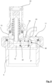
- a change in the pressure within the medium channel 14 is not detected according to the Venturi principle as explained above, but by means of a so-called pitot tube 35.
- Said pitot tube 35 has an opening cross section 36 oriented perpendicularly to a direction of flow of the protective gas, through which protective gas flowing through can enter the pitot tube 35 and can finally be routed to a pressure sensor 24 .
- the occurrence of such a flow can be associated with the removal of filling material from the container 4 , so that the start and end of a removal of filling material from the container 1 can be detected on the basis of data recorded by the pressure sensor 24 , with the determination of a period of time over which the removal has taken place finally, a conclusion about the fill level of the filling material inside the container 4 can be drawn.
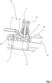
- FIG. 6 An alternative embodiment of a sensor device 10 in the Figures 6 to 8 is shown comprises an adapter element 11, which in comparison to the sensor devices 10 according to the Figures 3 to 5 is formed significantly smaller.
- Said sensor device 10 is connected to the gas connection 9 of the container 4 by means of a union nut 39 .
- the gas connection 9 as such does not have its own gas connection piece 17 in the example shown, so that a protective gas line can only be connected to the container 4 via the gas connection piece 13 of the adapter element 11 .
- the associated container 1 is therefore designed in such a way that it depends on the arrangement of the sensor device 10 on the gas connection 9 in order to be used as intended.
- the medium channel 14 is oriented at least substantially horizontally, as a result of which the volume of installation space required for the adapter element 11 is significantly reduced.
- the sensor device 10 also has a branch line 23, which is connected to the medium channel 14 by forming an angle 48 in the area of the constriction 20 , the angle 48 being formed here by a right angle.
- connection line 37 interacts at an end remote from the adapter element 11 with a pressure sensor 24 which is accommodated here in the associated telemetry module 12 .
- the latter has a cuboid housing 29 which is basically connected to the cover 19 of the container 1 in a force-transmitting manner independently of the adapter element 11 , in particular by means of a screw connection.
- the telemetry module 12 has an LED 38 here, by means of which an operating state of the telemetry module 12 or of the sensors 15 located therein can be displayed optically.
Landscapes
- Engineering & Computer Science (AREA)
- Mechanical Engineering (AREA)
- Physics & Mathematics (AREA)
- Fluid Mechanics (AREA)
- General Physics & Mathematics (AREA)
- Filling Or Discharging Of Gas Storage Vessels (AREA)
Description
- Die vorliegende Anmeldung betrifft ein Verfahren gemäß dem Oberbegriff von Anspruch 1.
- Ein Container, dessen Betrieb Gegenstand des Verfahrens ist, kann insbesondere dazu verwendet werden, ein wässriges, fließfähiges Füllgut vorzuhalten. Hierzu sind beispielsweise sogenannte Fruchtzubereitungen zu nennen, die beispielsweise bei einem Hersteller abgefüllt und sodann an Abnehmer vertrieben werden. Der Container umfasst insbesondere ein Gestell sowie einen Behälter, wobei der Behälter mittels des Gestells in einem Abstand oberhalb eines Untergrundes lagerbar ist. Auf diese Weise ist der Behälter von seiner Unterseite her zugänglich. An besagter Unterseite verfügt der Behälter über mindestens eine Öffnung, mittels derer der Behälter mit Füllgut beladbar ist oder Füllgut aus dem Behälter entnehmbar ist. Um eine Kontamination des Füllguts insbesondere mit Sauerstoff zu vermeiden, verfügt der Behälter zudem über mindestens einen Gasanschluss, mittels dessen eine Schutzgasleitung an den Behälter anschließbar ist. Mittels einer solchen Schutzgasleitung ist es möglich, ein Schutzgas, beispielsweise Kohlendioxid, dem Behälter zuzuleiten. Auf diese Weise ist sichergestellt, dass neben dem Füllgut selbst ein Innenraum des Behälters ausschließlich mit dem Schutzgas gefüllt ist. Hierdurch wird erreicht, dass das in dem Behälter befindliche Füllgut nicht durch den Kontakt mit Umgebungsluft verdirbt.
- Der Anschluss der Schutzgasleitung an den Gasanschluss des Behälters erfolgt in aller Regel bevor eine Entnahmevorrichtung an die Öffnung des Behälters angeschlossen wird. Dies hat zur Folge, dass in dem Moment der Entnahme von Füllgut aus dem Behälter in jedem Falle bereits die Schutzgasleitung angeschlossen ist und jederzeit Schutzgas in den Innenraum des Behälters nachströmen kann. Entsprechend ist es üblich, die Schutzgasleitung erst dann von dem Behälter zu entfernen, wenn die Entnahme von Füllgut beendet ist. Insbesondere ist es denkbar, immer zuerst die Entnahmevorrichtung von der Öffnung zu trennen, bevor die Schutzgasleitung von dem Gasanschluss entfernt wird.
- Der Container ist vorzugsweise von Edelstahl gebildet, sodass er beliebig häufig verwendet, das heißt insbesondere be- und entladen, werden kann. Sofern das Füllgut eine vergleichsweise hohe Viskosität aufweist kann es sinnvoll sein, das Füllgut zur Entnahme aus dem Behälter mittels einer Pumpe abzupumpen. Um im Zuge der Entnahme des Füllguts aus dem Innenraum des Behälters eine ausreichende Nachströmung von Schutzgas sicherzustellen, ist es zudem vorteilhaft, wenn die Schutzgasleitung an eine Druckquelle angeschlossen ist, die das Schutzgas unter einen bestimmten Druck bereitstellt. Auf diese Weise ist sichergestellt, dass kein Fremdgas, insbesondere keine Umgebungsluft, unbeabsichtigter Weise in den Behälter einströmt.
- Container der eingangs beschriebenen Art sind im Stand der Technik bereits bekannt. Hierzu wird beispielhaft auf das Europäische Patent
EP 1 544 030 B1 verwiesen, dass sich mit einem Gestell eines solchen Containers befasst. - In der alltäglichen Logistik betreffend derartige Container hat sich herausgestellt, dass es wünschenswert ist, den Füllstand eines solchen Containers nachvollziehen zu können. Hierzu ist es üblich, einen jeweiligen Container im Zuge der Entnahme von Füllgut aus dessen Behälter auf einer Waage zu platzieren, mittels derer eine Veränderung der Masse des Containers feststellbar ist, woraus wiederum ein Rückschluss auf die entnommene Menge des Füllguts gezogen werden kann. Diese Vorgehensweise ist jedoch insoweit von Nachteil, als in jedem Falle eine solche Waage notwendig ist, um den Füllstand des Containers zu überwachen. Hierzu ist anzumerken, dass es in der Praxis sehr üblich ist, dass ein jeweiliger Container etappenweise, womöglich über einen längeren Zeitraum hinweg, geleert wird. Eine Leerung "in einem Zug" ist demgegenüber vergleichsweise unüblich. Mithin besteht grundsätzlich das Interesse, die Füllstände einzelner Container individuell nachzuhalten, sodass jederzeit Klarheit darüber besteht, welche Menge des Füllguts noch verfügbar ist.
- Die
US 2018/0052030 A1 offenbart eine Fluidstandsmessanordnung umfassend einen Behälter mit einem Einlass und einem an der Unterseite angeordneten Auslass für das Füllgut. Mehrere Strömungsleitungen erstrecken sich von einer Mediumzufuhr zu dem Behälter, wobei jede Strömungsleitung in einer anderen Höhe im Inneren des Behälters mündet. Eine erste Strömungsleitung mündet auf einer untersten Ebene, eine zweite Strömungsleitung mündet ein einer mittleren Ebene und eine dritte Strömungsleitung mündet auf einer höchsten Ebene. Ein Druckaufnehmer ist in jeder der Strömungsleitungen angeordnet, um den Druck innerhalb jeder Strömungsleitung zu messen. Wenn der Fluidstand in dem Behälter die niedrigste Füllstandshöhe überschreitet und dadurch die Mündung der ersten Strömungsleitung abdeckt, erfasst der Druckaufnehmer einen starken Druckanstieg im Vergleich zu dem Ausgangsdruck in der Strömungsleitung. Dieser Druckanstieg zeigt den Flüssigkeitsstand in dem Behälter an. Die Druckaufnehmer in den drei Strömungsleitungen messen solange eine konstanten Druck, bis der Füllstand die Mündung der untersten, mittleren oder höchsten Strömungsleitung überschritten hat. Die erfasste Füllstände werden genutzt, um den Auslass und / oder der Einlass ganz oder teilweise zu öffnen oder zu schließen, um den Flüssigkeitsstand entweder zu erhöhen oder zu verringern. - Die
CN 205 615 969 U offenbart einen Tank zur Aufnahme von Methanol mit einem Einlassrohr und einem Auslassrohr. An der Oberseite des Tanks sind ein erstes Gaseinlassrohr, ein zweites Gaseinlassrohr und ein drittes Gaseinlassrohr für die Zufuhr von Stuckstoff angeordnet, wobei das erste Gaseinlassrohr oben, das zweite Gaseinlassrohr unten und das dritte Gaseinlassrohr in der Mitte des Tanks münden. Das erste Lufteinlassrohr ist mit einem Messgerät ausgestattet, das den Druck an der Flüssigkeitsoberfläche messen kann. Das zweite Gaseinlassrohr leitet den Stickstoff zum Boden des Tanks. Ein Messgerät ist an dem zweiten Gaseinlassrohr angeordnet, um die Druckdifferenz zwischen dem Boden der Flüssigkeit und der Flüssigkeitsoberfläche zu messen. Aus der Druckdifferenz wird die Flüssigkeitshöhe errechnet. Eine weiteres Messgerät an dem dritten Gaseinlassrohr misst die Druckdifferenz zwischen dem zweiten Gaseinlassrohr und dem dritten Gaseinlassrohr, um die die Dichte der Flüssigkeit zu ermitteln. - Der vorliegenden Anmeldung liegt die Aufgabe zugrunde, ein Verfahren bereitzustellen, mittels dessen ein Füllstand eines jeweiligen Containers im Vergleich zum Stand der Technik einfacher ermittelbar ist.
- Die zugrunde liegende Aufgabe wird erfindungsgemäß mittels eines Verfahrens mit den Merkmalen des Anspruchs 1 gelöst. Vorteilhafte Ausgestaltungen ergeben sich aus den Unteransprüchen 2 bis 8.
- Das Verfahren sieht vor, dass vor der Entnahme von Füllgut aus dem Behälter eine Schutzgasleitung an den Gasanschluss angeschlossen und mit Druck beaufschlagt wird. Ein entsprechendes Vorgehen ist eingangs bereits dargelegt worden. Weiterhin wird eine Entnahmevorrichtung an die Öffnung des Behälters angeschlossen, sodass mittels der Entnahmevorrichtung Füllgut aus dem Behälter entnommen werden kann. Grundsätzlich sind der Anschluss der Schutzgasleitung sowie der Anschluss der Entnahmevorrichtung an den Container keiner zeitlichen Reihenfolge unterworfen. Entscheidend ist lediglich, dass vor der tatsächlichen Entnahme des Füllguts die Schutzgasleitung an den Behälter angeschlossen und mit Druck beaufschlagt wird, sodass Schutzgas nachgeführt werden kann und somit ein in dem Behälter aufgrund der Entnahme des Füllguts freiwerdendes Volumen ausfüllen kann.
- Erfindungsgemäß werden zumindest während eines Zeitraums der Entnahme des Füllguts aus dem Behälter mittels mindestens eines Drucksensors Daten betreffend einen Druck des Schutzgases in dem Mediumkanal erfasst. Der "Mediumkanal" kann grundsätzlich jede Leitung betreffen, durch die hindurch das Schutzgas in den Behälter einströmen kann. Insbesondere kann der Mediumkanal unmittelbar an der Schutzgasleitung oder an bzw. in dem Container selbst ausgebildet sein. Alternativ ist es jedoch ebenso vorstellbar, dass der Mediumkanal an einem Adapterelement ausgebildet ist, dass in Kraft übertragender Weise an den Container angeschlossen wird. Beispielsweise ist es denkbar, ein entsprechendes Adapterelement an den Gasanschluss des Behälters anzuschließen, wobei das Adapterelement mit dem Drucksensor ausgestattet ist. Die Schutzgasleitung kann in einem solchen Fall an das Adapterelement angeschlossen werden, sodass das mittels der Schutzgasleitung bereitgestellte Schutzgas durch das Adapterelement bzw. einen Mediumkanal desselben hindurch zu dem Gasanschluss des Behälters und schließlich in den Innenraum des Behälters einströmen kann.
- Für das erfindungsgemäße Verfahren ist es lediglich erforderlich, dass mindestens ein Mediumkanal, durch den das Schutzgas hindurch in den Behälter einströmt, mit einem Drucksensor ausgestattet ist, sodass ein Druck des Schutzgases in dem Mediumkanal zumindest mittelbar mittels des Drucksensors erfassbar ist. Der "Druck" muss dabei nicht notwendigerweise einen Gesamtdruck des Schutzgases bezeichnen. Stattdessen ist es ebenso möglich, dass der erfasste Druck lediglich einen Teildruck des Schutzgases beschreibt, beispielsweise einen dynamischen Druck oder einen statischen Druck des Schutzgases. Der dynamische Druck des Schutzgases ist durch dessen Strömungsgeschwindigkeit innerhalb des Mediumkanals bestimmt.
- Mittels der Ermittlung eines Drucks des Schutzgases in dem Mediumkanal ist es erfindungsgemäß möglich, Zeitpunkte festzustellen, zu denen eine Entnahme von Füllgut aus dem Behälter beginnt und endet. Die Differenz aus diesen Zeitpunkten ergibt einen Zeitraum, innerhalb dessen eine Entnahme von Füllgut aus dem Behälter stattgefunden hat. Die Ausprägung dieses Zeitraums lässt wiederum einen Rückschluss darauf zu, wie viel Füllgut aus dem Behälter entnommen wurde. Auf diese Weise ist es möglich, ausgehend von einem vollständig gefüllten Behälter nachzuverfolgen, welchen Füllstands der Behälter nach der Entnahme von Füllgut noch aufweist, wobei der im Stand der Technik bekannte Einsatz einer Waage ausbleiben kann. Wird beispielsweise mittels Auswertung eines Druckverlaufs des Schutzgases festgestellt, dass über einen Zeitraum von 10 Minuten hinweg Füllgut aus dem Behälter entnommen wurde, kann bei bekanntem Massestrom der Entnahme des Füllgutes aus dem Behälter, dessen verbleibender Füllstand in Bezug auf den Ausgangsfüllstand zu Beginn der Entnahme genau ermittelt werden.
- Eine Erfassung des statischen Drucks innerhalb des Mediumkanals kann beispielsweise mittels einer Stichleitung erfolgen, die sich schräg, vorzugsweise senkrecht, zu einer Längsachse des Mediumkanals erstreckt und einen Mediumkanal angeschlossen ist, wobei der Drucksensor an einem dem Mediumkanal abgewandten Ende der Stichleitung angeordnet ist. Bei einer solchen Anordnung ist eine Strömung des Schutzgases durch den Mediumkanal senkrecht zu der Stichleitung orientiert, sodass ein mittels des am Ende der Stichleitung angeordneten Drucksensors erfasster Druck frei von einem Anteil des dynamischen Drucks an den Gesamtdruck des Schutzgases ist. Stattdessen wird mittels eines solchen Drucksensors lediglich der statische Druck des Schutzgases erfasst.
- Alternativ oder zusätzlich ist es ebenso denkbar, den Mediumkanal mit einem Pitotrohr auszustatten, das einen sich in längsachsparallele Richtung des Mediumkanals erstreckenden Abschnitt aufweist. Mittels eines Öffnungsquerschnitts ist ein solches Pitotrohr dazu geeignet, durch den Mediumkanal strömendes Schutzgas aufzunehmen, wobei mittels eines an einem dem Mediumkanal abgewandten Ende des Pitotrohrs angeordneten Drucksensors ein Gesamtdruck des Schutzgases erfassbar ist, das heißt die Summe eines statischen und eines dynamischen Drucks des Schutzgases. Mittels kombinierter Erfassung des Gesamtdrucks sowie des statischen Drucks kann mittels Subtraktion auf den dynamischen Druck des Schutzgases rückgeschlossen werden. Eine kombinierte Erfassung von Gesamtdruck und statischem Druck ist beispielsweise mittels eines Prandtl-Rohrs möglich, dessen Einsatz hier gleichermaßen vorstellbar ist. Alternative Anordnungen eines Drucksensors an oder in einem Mediumkanal sind selbstverständlich ebenso vorstellbar.
- Mittels der Ermittlung eines Drucks des Schutzgases in dem Mediumkanal ist es erfindungsgemäß möglich, Zeitpunkte festzustellen, zu denen eine Entnahme von Füllgut aus dem Behälter beginnt und endet. Die Differenz aus diesen Zeitpunkten ergibt einen Zeitraum, innerhalb dessen eine Entnahme von Füllgut aus dem Behälter stattgefunden hat. Die Ausprägung dieses Zeitraums lässt wiederum einen Rückschluss darauf zu, wie viel Füllgut aus dem Behälter entnommen wurde. Auf diese Weise ist es möglich, ausgehend von einem vollständig gefüllten Behälter nachzuverfolgen, welchen Füllstands der Behälter nach der Entnahme von Füllgut noch aufweist, wobei der im Stand der Technik bekannte Einsatz einer Waage ausbleiben kann. Wird beispielsweise mittels Auswertung eines Druckverlaufs des Schutzgases festgestellt, dass über einen Zeitraum von 10 Minuten hinweg Füllgut aus dem Behälter entnommen wurde, kann bei bekanntem Massestrom der Entnahme des Füllgutes aus dem Behälter, dessen verbleibender Füllstand in Bezug auf den Ausgangsfüllstand zu Beginn der Entnahme genau ermittelt werden.
- Das erfindungsgemäße Verfahren hat viele Vorteile. Insbesondere ist es möglich, eine Vielzahl von Containern dezentral und ohne weitere externe Hilfsmittel zu überwachen und den Füllstand jedes einzelnen Containers individuell nachzuhalten. Hierzu ist es lediglich erforderlich, mindestens einen Drucksensor in oder an einem Mediumkanal des Containers anzuordnen und mittels des Drucksensors erfasste Daten zu verarbeiten. Die Ausstattung eines jeweiligen Containers mit einem solchen Drucksensor kann besonders einfach mittels eines an den Gasanschluss einsetzbaren Adapterelements erfolgen, wie nachstehend gesondert dargelegt wird.
- In einer Weiterbildung des erfindungsgemäßen Verfahrens kann in Abhängigkeit der Druckverhältnisse zudem eine Aussage darüber getroffen werden, wie groß der Volumenstrom des in den Behälter nachströmenden Schutzgases und demzufolge auch der Massenstrom des aus dem Behälter entnommenen Füllguts sind. Auf diese Weise kann als zusätzlicher Parameter die "Entnahmegeschwindigkeit" betreffend das Füllgut berücksichtigt werden. Der Volumenstrom des nachströmenden Schutzgases ist proportional zu dem Massenstrom des aus dem Behälter entnommenen Füllguts, so dass sich der Füllstand des Behälters quantitativ genau bestimmen lässt. Wird der Massestrom des entnommenen Füllgutes indes nicht ermittelt, kann der Füllstand anhand der ermittelten Entnahmedauer unter Annahme von typische Werten für den Massestrom während der Entnahme für ein spezifisches Füllgut hinlänglich genau abgeschätzt werden. In jedem Fall kann über die Auswertung der Druckkurve zumindest zuverlässig die erstmalige Entnahme von Füllgut aus dem vollständig gefüllten Behälter und die vollständige Entleerung des Behälters festgestellt werden. Eine qualitative Füllstandskontrolle ist daher mit dem Drucksensor in jedem Fall möglich.
- In einer vorteilhaften Ausgestaltung des erfindungsgemäßen Verfahrens wird das Schutzgas in dem Mediumkanal beschleunigt, insbesondere mittels einer in dem Mediumkanal angeordneten Engstelle. Eine solche Engstelle ist dadurch definiert, dass ein Querschnitt des Mediumkanals im Bereich der Engstelle kleiner ist als ein Querschnitt des Mediumkanals außerhalb der Engstelle. Die Beschleunigung des Schutzgases im Bereich der Engstelle führt dazu, dass ein dynamischer Druck des Schutzgases lokal ansteigt, während der statische Druck entsprechend abnimmt. Dies betrifft zumindest solche Fälle, in denen ein von einer Druckquelle zur Verfügung gestellter Gesamtdruck des Schutzgases zumindest im Wesentlichen, insbesondere vollständig, konstant ist. Die bereichsweise Beschleunigung des Schutzgases innerhalb des Mediumkanals erleichtert insbesondere eine Feststellung von Änderungen eines Volumenstroms, der durch den Mediumkanal in den Innenraum des Behälters einströmen.
- Die Erhebung von Daten betreffend eine derartige Änderung ist insoweit von Vorteil als derartige Daten dazu verwendet werden können, den Massenstrom, mit dem Füllgut aus dem Behälter entnommen wird, indirekt zu bestimmen. Dem liegt die Überlegung zugrunde, dass eine umso schnellere Entnahme von Füllgut aus dem Behälter zu einem schnelleren Nachströmen von Schutzgas durch den Mediumkanal führt. Die Erhebung der Druckverhältnisse in den Mediumkanal, beispielsweise nach dem Venturi-Prinzip oder mittels eines Pitotrohrs, kann demzufolge behilflich sein, eine entsprechende Aussage zu treffen. Der erfasste statische und dynamische Druck erlaubt über das Bernoullische Gesetz die Berechnung der Strömungsgeschwindigkeit des Schutzgases in einem Strömungsquerschnitt. Die Berechnung des Massestroms des einströmenden Schutzgases ergibt sich sodann aus dem Produkt von Dichte des Schutzgases, der berechneten Strömungsgeschwindigkeit und dem Strömungsquerschnitt. Alternativ oder zusätzlich ist es denkbar, einen Massenstrom des durch die Öffnung aus dem Behälter austretenden Füllguts direkt und separat zu ermitteln, wobei beispielsweise die Anordnung eines entsprechenden Strömungssensors an der Öffnung des Behälters möglich ist.
- In einer weiterhin vorteilhaften Ausgestaltung des erfindungsgemäßen Verfahrens werden mittels des Drucksensors erfasste Daten mittels eines Datenloggers zumindest zeitweise gespeichert. Insbesondere ist es denkbar, die erfassten Daten zumindest so lange zu speichern, bis der Behälter vollständig entleert ist. Weiterhin kann es von Vorteil sein, wenn die mittels des Drucksensors erfassten Daten mittels einer Auswerteeinheit verarbeitet werden. Letztere kann beispielsweise mittels eines hinterlegten Algorithmus Veränderungen des in dem Mediumkanal vorliegenden Drucks feststellen und darauf basierend Zeitpunkte bestimmen, zu denen die Entnahme von Füllgut aus dem Behälter beginnt und/oder endet.
- Um erfasste Daten extern auswerten oder bereits an dem Container mittels einer Auswerteeinheit ausgewerteten Daten evaluieren und einsehen zu können, ist es weiterhin von besonderem Vorteil, wenn entsprechende Daten mittels eines Senders kabellos versendet werden. Ein solcher Sender kann beispielsweise das normale Mobilfunknetz verwenden, um Daten zu übertragen. Auf diese Weise ist es möglich, dass eine befugte Person die entsprechenden Daten abruft und einsieht und darauf basierend individuelle Entscheidungen treffen kann.
- Der in dem Verfahren verwendete Container umfasst mindestens eine Sensoreinrichtung, die ein Adapterelement aufweist. Dieses Adapterelement ist dazu geeignet, vorzugsweise lösbar an den Gasanschluss des Behälters angeschlossen zu werden, sodass die Sensoreinrichtung an den Container angeschlossen ist. Das Adapterelement umfasst mindestens einen Gasstutzen und mindestens einen Mediumkanal, wobei der Gasstutzen dazu geeignet ist, eine Schutzgasleitung aufzunehmen, sodass Schutzgas ausgehend von der Schutzgasleitung durch den Gasstutzen sowie durch den Mediumkanal des Adapterelements hindurch zu dem Gasanschluss des Behälters und schließlich in den Innenraum des Behälters leitbar ist. Ferner umfasst die Sensoreinrichtung mindestens einen Drucksensor, der zumindest mittelbar mit dem Mediumkanal zusammenwirkt. Mittels des mindestens einen Drucksensors sind Daten betreffend einen in dem Mediumkanal vorliegenden Druck des Schutzgases erfassbar. Wie vorstehend bereits dargelegt, kann es sich bei diesem Druck sowohl um einen Gesamtdruck des Schutzgases als auch um Teildrücke desselben handeln, beispielsweise einen dynamischen Druck und/oder einen statischen Druck.
- Das erfindungsgemäße Verfahren ist mittels des Containers besonders einfach durchführbar. Insbesondere können mittels des mindestens einen Drucksensors besonders einfach Daten betreffend einen Druck innerhalb des Mediumkanals erhoben werden, woraus in der beschriebenen Weise ein Rückschluss auf eine entnommene Menge von Füllgut und mithin auf einen Füllstand eines jeweiligen Containers mit Füllgut gezogen werden kann.
- In einer besonders vorteilhaften Ausgestaltung des Containers weist der Mediumkanal des Adapterelements mindestens eine Engstelle auf, an der ein Querschnitt des Mediumkanals gegenüber einem Querschnitt des Mediumkanals außerhalb der Engstelle reduziert ist. Vorteilhafterweise ist die Engstelle derart in den Mediumkanal eingebunden, dass der Querschnitt des Mediumkanals beidseits der Engstelle aufgeweitet ist. Mit anderen Worten ist der Mediumkanal vorteilhafterweise derart ausgestaltet, dass durch den Mediumkanal strömendes Gas im Bereich der Engstelle beschleunigt wird und sodann nach Verlassen der Engstelle aufgrund der insbesondere konischen Aufweitung des Mediumkanals abgebremst wird. Im Zuge der Beschleunigung des Gases wird der dynamische Druck desselben innerhalb des Mediumkanals lokal erhöht und der statische Druck entsprechend reduziert, soweit der Gesamtdruck des Gases, das beispielsweise aus einer unter Druck stehenden Gasflasche bereitgestellt wird, konstant bleibt.
- Weiterhin ist es von besonderem Vorteil, wenn die Sensoreinrichtung mindestens eine Stichleitung aufweist, die strömungstechnisch mit den Mediumkanal des Adapterelements zusammenwirkt. Eine Längsachse der Stichleitung ist vorzugsweise senkrecht zu einer Längsachse des Mediumkanals orientiert, sodass die Stichleitung senkrecht auf den Mediumkanal trifft. Besonders zu bevorzugen ist eine Ausführungsform, bei der die Stichleitung im Bereich einer vorstehend genannten Engstelle auf den Mediumkanal trifft. Mittels einer solchen Stichleitung ist es möglich, an deren dem Mediumkanal abgewandten Ende einen Drucksensor anzuordnen, mittels dessen Änderungen des Drucks innerhalb der Stichleitung erfassbar sind. Eine solche Ausgestaltung der Sensoreinrichtung ermöglicht die Messung einer Veränderung des statischen Drucks innerhalb des Mediumkanals, die sich aufgrund einer Strömungsgeschwindigkeit des durch den Mediumkanal strömenden Gases ergibt. Dem liegt die Überlegung zugrunde, dass eine umso größere Strömungsgeschwindigkeit des Gases im Bereich der Engstelle zu einem umso höheren dynamischen Druck und umgekehrt analog hierzu zu einem umso niedrigeren statischen Druck des Gases in dem Mediumkanal führt, soweit ein Gesamtdruck des Gases, der mittels einer Druckquelle zur Verfügung gestellt wird, konstant ist.
- Infolge der Veränderung des statischen Drucks in dem Mediumkanal ändert sich auch der Druck in der Stichleitung, die aufgrund ihrer bevorzugt senkrechten Ausrichtung zum Mediumkanal ausschließlich mit dem statischen Druck des Gases beaufschlagt ist, wobei diese Veränderung mittels des Drucksensors ermittelbar ist. Auf diese Weise kann zunächst grundsätzlich festgestellt werden, das Schutzgas durch den Mediumkanal strömt und mithin offenbar eine Entnahme von Füllgut aus dem Behälter des Containers stattfindet. Anderenfalls würde das Schutzgas nicht in den Behälter einströmen, sondern sich womöglich lediglich der statische Druck erhöhen, je nach Druckniveau der Quelle des Schutzgases. Im Ergebnis ermöglicht demzufolge die Kombination aus Engstelle, Stichleitung und Drucksensor eine Überwachung der Strömungsverhältnisse eines Schutzgases durch die Sensoreinrichtung.
- Mittels Aufzeichnung und anschließender Auswertung eines Verlaufs von mittels des Drucksensors ermittelter Daten kann schließlich eine Aussage darüber getroffen werden, über welchen Zeitraum hinweg Schutzgas durch die Sensoreinrichtung hindurch in den Innenraum des Behälters eingeströmt ist. Hieraus ist der Rückschluss möglich, dass über denselben Zeitraum hinweg Füllgut aus dem Behälter entnommen wurde. In Kenntnis dieses Zeitraums ist es folglich möglich, eine Aussage über einen verbleibenden Füllstand des Behälters zu machen, nachdem der Zeitraum der Entnahme von Füllgut beendet ist. Wird beispielsweise mittels Auswertung eines Druckverlaufs des Schutzgases festgestellt, dass über einen Zeitraum von 10 Minuten hinweg Füllgut aus dem Behälter entnommen wurde, kann bei bekanntem Massestrom der Entnahme des Füllgutes aus dem Behälter, dessen verbleibender Füllstand in Bezug auf den Ausgangsfüllstand zu Beginn der Entnahme ermittelt werden. Eine Druckverlaufskurve, die mittels des Drucksensors erfasst und anschließend aufgezeichnet wurde, kann insbesondere in Momenten, in denen eine Pumpe zur Entnahme des Füllguts aktiviert und deaktiviert wird, charakteristische Ausschläge aufweisen, mittels deren Interpretation in der oben beschriebenen Weise eine Aussage über eine Entnahmedauer und daraus resultierend eine entnommene Menge des Füllguts möglich ist. Beispielsweise kann die Druckverlaufskurve im Moment der Aktivierung der Pumpe einen schlagartigen Abfall zeigen, was auf eine sich einstellende Strömung des Schutzgases innerhalb des Mediumkanals zurückzuführen ist. Diese setzt ein, da ein freiwerdendes Volumen im Innenraum des Behälters mit Schutzgas "nachgefüllt" wird, das durch den Gasanschluss des Behälters - und somit vorher durch den Mediumkanal der Sensoreinrichtung - in den Innenraum einströmt. Infolge der Strömung des Schutzgases durch den Mediumkanal fällt im Bereich der Engstelle aufgrund des Anstiegs des dynamischen Drucks der statische Druck ab, was mittels des in der an die Engstelle angeschlossenen Stichleitung vorhandenen Drucksensors als Druckabfall registriert wird. Umgekehrt steigt der statische Druck in der Stichleitung bei Beendigung der Entnahme von Füllgut aus dem Behälter wieder an, sodass der Zeitpunkt der Beendigung der Entnahme feststellbar ist.
- Eine Überwachung des Füllstands eines Behälters ist grundsätzlich im Zuge der Entnahme des Füllguts von besonderem Interesse, da bei einer Befüllung in aller Regel ohnehin der Behälter vollständig gefüllt wird, sodass anschließend immer ein voller Behälter vorliegt. Bei der Entnahme ist es hingegen sehr üblich, dass das Füllgut etappenweise, womöglich über mehrere Tage verteilt, entnommen wird, sodass eine genaue Verfolgung der Abnahme des Füllstands des Behälters von Interesse ist. Eine Entnahme des Füllguts aus einem jeweiligen Behälter kann je nach Verwendung des Füllguts sehr individuell sein und folgt in der Praxis selten einem immer gleichen Muster.
- Der Container ist nachstehend anhand eines Ausführungsbeispiels, das in den Figuren dargestellt ist, näher erläutert. Es zeigt:
- Fig. 1:
- Eine schematische Seitenansicht eines Containers,
- Fig. 2:
- Eine perspektivische Ansicht eines Deckels des Containers gemäß
Figur 1 , - Fig. 3:
- Einen vertikalen Querschnitt durch eine Sensoreinrichtung des Containers gemäß
Figur 1 , - Fig. 4:
- Ein Detail der Sensoreinrichtung gemäß
Figur 3 , - Fig. 5:
- Ein Detail einer alternativen Sensoreinrichtung,
- Fig. 6:
- Eine perspektivische Ansicht eines Deckels für einen Container gemäß
Figur 1 , jedoch mit einer alternativen Sensoreinrichtung, - Fig. 7:
- Einen vertikalen Querschnitt durch die Sensoreinrichtung gemäß
Figur 6 , - Fig. 8:
- Ein Detail der Sensoreinrichtung gemäß
Figur 7 und - Fig. 9:
- Eine Druckverlaufskurve während einer Entnahme von Füllgut aus einem Container.
- Ein Ausführungsbeispiel, das in den
Figuren 1 bis 9 gezeigt ist, umfasst einen Container 1, der einen Behälter 4 sowie ein Gestell 2 umfasst. Das Gestell 2 umfasst wiederum eine Mehrzahl von Beinen 42, mittels derer der Container 1 auf einem Untergrund 3 aufsteht. Der Behälter 4 ist mittels des Gestells 2 derart beabstandet von dem Untergrund 3 gelagert, dass eine Unterseite 6 des Behälters 4 von unten her zugänglich ist. Insbesondere befindet sich eine tiefste Stelle 43 des Behälters 4 in einem Abstand 5 von dem Untergrund 3. Besagte tiefste Stelle 43 wirkt mit einer Öffnung 7 zusammen, durch die hindurch ein Innenraum 8 des Behälters 4 mit Füllgut beladbar ist bzw. besagtes Füllgut aus dem Innenraum 8 entnehmbar ist. Hierzu wirkt der Behälter 4 mit einem Anschlussrohr 30 zusammen, dass einen 90° Winkel aufweist, sodass ein Querschnitt der Öffnung 7 vertikal orientiert ist. Die Öffnung 7 wirkt hier mit einem Anschlussstutzen zusammen, sodass ein Füllgutschlauch an die Öffnung 7 ankoppelbar ist, mittels dessen Füllgut aus dem Behälter 4 entnehmbar ist oder umgekehrt Füllgut in den Behälter 4 einfüllbar ist. - An einer Oberseite 18 weist der Container 1 einen Deckel 19 auf, an dem ein Gasanschluss 9 und ein Überdruckventil 31 ausgebildet sind. Dieser Gasanschluss 9 dient dazu, mit einer in den Figuren nicht dargestellten Schutzgasleitung zusammenzuwirken. Mittels einer solchen Schutzgasleitung wird die Möglichkeit geschaffen, dem Innenraum 8 des Behälters 4 ein Schutzgas zuzuleiten, beispielsweise Kohlendioxid. Ein solches Schutzgas ist bedeutsam, um ein in dem Behälter 4 verfügbares Freivolumen, das nicht mit einem jeweiligen Füllgut gefüllt ist, auszufüllen. Insbesondere ist es oftmals zu vermeiden, dass das Füllgut mit Sauerstoff in Kontakt kommt, woraufhin das Füllgut oxidieren würde. Das Schutzgas verhindert derartige Reaktionen und trägt mithin zu einer langen Haltbarkeit des Füllguts innerhalb des Behälters 4 bei. Die Schutzgasleitung ist typischerweise an eine Druckquelle angeschlossen, mittels derer das jeweilige Schutzgas unter einem Druck zur Verfügung gestellt wird. Auf diese Weise ist sichergestellt, dass im Zuge einer Entnahme des Füllguts aus dem Behälter 4 unmittelbar entsprechend Schutzgas in das freiwerdende Volumen in den Behälter 4 nachströmt.
- In dem gezeigten Beispiel wirkt der Gasanschluss 9 mit einem Gasstutzen 17 zusammen, der hier dazu geeignet ist, mit einem Schnellverschluss 32 der Schutzgasleitung zusammenzuwirken. Auf diese Weise ist es besonders einfach möglich, die Schutzgasleitung werkzeuglos an den Gasanschluss 9 anzuschließen und eine strömungstechnische Verbindung mit dem Innenraum 8 des Behälters 4 herzustellen. Umgekehrt ist es ebenso einfach möglich, die Schutzgasleitung wieder von den Gasanschluss 9 zu entfernen.
- Der Container 1 umfasst eine Sensoreinrichtung 10, die ein Adapterelement 11 sowie ein Telemetriemodul 12 umfasst. Das Adapterelement 11 umfasst einen Mediumkanal 14 sowie einen Gasstutzen 13. Weiterhin weist das Adapterelement 11 einen Anschlussabschnitt 44 auf, der in komplementärerer Weise zu dem Gasstutzen 17 des Gasanschlusses 9 des Behälters 4 ausgebildet ist. Auf diese Weise ist die Sensoreinrichtung 10 an dem Gasstutzen 17 fixierbar, wobei die Sensoreinrichtung 10 gewissermaßen auf den Gasstutzen 17 aufsteckbar bzw. aufgesteckt ist. Der Gasstutzen 17 verfügt hierbei über einen Dichtungsring 34, mittels dessen das Adapterelement 11 gegen den Gasanschluss 9 abdichtbar ist. Die Mechanik zwischen Anschlussabschnitt 44 und Gasstutzen 17 ist prinzipiell identisch zu derjenigen, mittels derer eine Schutzgasleitung an den Gasstutzen 17 anschließbar ist. Auf diese Weise ist es besonders einfach möglich, die Sensoreinrichtung 10 an den Container 1 zu fixieren, wobei die Sensoreinrichtung 10 mittels ihres Adapterelements 11 lediglich werkzeuglos sowie zerstörungsfrei lösbar auf den Gasstutzen 17 aufgesteckt wird und dort einrastet.
- An einem dem Deckel 19 des Containers 1 abgewandten Ende weist das Adapterelement 11 den Gasstutzen 13 auf, der in dem gezeigten Beispiel mit einem Schnellverschluss 32 zusammenwirkt. Der Schnellverschluss 32 ist mittels eines Dichtungsrings 33 gegen den Gasstutzen 13 des Adapterelements 11 abgedichtet. Der Gasstutzen 13 ist hier in besonders vorteilhafter Weise kompatibel zu den Gasstutzen 17 des Behälters 4 ausgebildet. Insbesondere gibt der Gasstutzen 13 des Adapterelements 11 den Gasstutzen 17 des Gasanschlusses 9 zumindest im Wesentlichen, vorzugsweise vollständig, identisch wieder. Auf diese Weise ist sichergestellt, dass eine jeweilige Schutzgasleitung ohne jegliche Notwendigkeit einer Anpassung oder Veränderung anstelle an den Gasstutzen 17 des Gasanschlusses 9 unmittelbar an den Gasstutzen 13 des Adapterelements 11 angeschlossen werden kann. Auf diese Weise ist der Container 1 ohne jegliche Umstellung weiter verwendbar, obwohl der eigentliche Gasanschluss 9 des Containers 1 nunmehr zur Fixierung der Sensoreinrichtung 10 an dem Container 1 genutzt wird. Der Gasstutzen 13 des Adapterelements 11 wirkt strömungstechnisch mit dessen Mediumkanal 14 zusammen, sodass nach Anschluss einer Schutzgasleitung an den Gasstutzen 13 (hier unter Verwendung des Schnellverschlusses 32) das jeweilige Schutzgas unmittelbar durch den Mediumkanal 14 hindurch zu dem Gasanschluss 9 des Behälters 4 und schließlich in den Innenraum 8 des Behälters 4 strömen kann.
- Das Telemetriemodul 12 der Sensoreinrichtung 10 umfasst in dem gezeigten Beispiel eine Mehrzahl von Sensoren 15 sowie einen Sender 16. Insbesondere weist das Telemetriemodul 12 einen Geopositionssensor 41, einen Beschleunigungssensor 25, einen Temperatursensor 28, einen Datenlogger 26 sowie eine Auswerteinheit 27 auf. Diese Bauteile des Telemetriemoduls 12 sind gemeinsam in einem Gehäuse 29 untergebracht, das einen Schutz besagter Bauteile vor äußeren Einwirkungen, insbesondere Feuchtigkeit und Schmutz, bereitstellt. Die Sensoren 15 sind dazu geeignet, Daten betreffend mindestens einen Zustandsparameter des Containers 1 und/oder einen Zustandsparameter des in dem Container 1 gelagerten Füllguts zu erfassen. Besagte Daten sind - ggf. nach Zwischenspeicherung in dem Datenlogger 26 sowie gegebenenfalls einer Verarbeitung mittels der Auswerteinheit 27 - mittels des Senders 16 versendbar, sodass besagte Daten aus der Ferne kabellos abgerufen werden können. Beispielsweise ist es denkbar, eine Absolutposition des Containers 1 mittels des Geopositionssensors 41 zu erfassen und mittels des Senders 16 zu versenden. Auf diese Weise ist es beispielsweise möglich, dass ein Kunde, der ein jeweiliges Füllgut erworben hat, einen Standort des Containers 1 überwachen kann und auf diese Weise abschätzen kann, zu welchem Zeitpunkt der Container 1 in seinem Betrieb zu erwarten ist. In derselben Weise ist es denkbar, eine Temperatur des Füllguts dauerhaft zu überwachen, wodurch eine Qualitätssicherung vereinfacht wird. Mittels des Datenloggers 26 sind die erfassten Daten speicherbar, sodass zudem nicht nur jeweils aktuelle Datensätze abgerufen werden können, sondern insbesondere auch eine Historie auswertbar ist. Mittels des mindestens einen Beschleunigungssensors 25 sind ferner Beschleunigungszustände des Containers 1 erfassbar, wobei bei starken Ausschlägen beispielsweise auf einen Unfall geschlossen werden kann.
- In dem gezeigten Ausführungsbeispiel gemäß
Figur 3 umfasst der Mediumkanal 14 des Adapterelements 11 eine Engstelle 20, in deren Bereich ein Querschnitt 21 des Mediumkanals 14 gegenüber einem Querschnitt 22 außerhalb der Engstelle 20 reduziert ist. Insbesondere ist die Engstelle 20 derart ausgebildet, dass sich der Mediumkanal 14 beidseits der Engstelle 20 erweitert. Auf diese Weise ist der Mediumkanal 14 im Bereich der Engstelle 20 in Form einer Venturi-Düse ausgebildet. Die Reduktion des Querschnitts des Mediumkanals 14 führt dazu, dass das durch den Mediumkanal 14 strömende Schutzgas im Bereich der Engstelle 20 beschleunigt wird. Demzufolge ist eine Strömungsgeschwindigkeit des Schutzgases 20 im Bereich der Engstelle 20 größer als in einem Bereich außerhalb der Engstelle 20. Dies führt dazu, dass ein dynamischer Druck des Schutzgases im Bereich der Engstelle 20 ansteigt, wodurch umgekehrt ein statischer Druck, der hydrostatisch auf eine Wandung des Mediumkanals 14 drückt, abnimmt. - Der Mediumkanal 14 wirkt weiterhin mit einer Stichleitung 23 zusammen, deren Längsachse senkrecht zu einer Längsachse des Mediumkanals 14 ausgerichtet ist. Mit anderen Worten trifft die Stichleitung 23 unter einem Winkel 48 auf den Mediumkanal 14 im Bereich der Engstelle 20, der hier 90° beträgt. An einem der Mediumkanal 14 abgewandten Ende wirkt die Stichleitung 23 mit einem Drucksensor 24 zusammen. Dieser ist dazu geeignet, Daten betreffend einen statischen Druck innerhalb der Stichleitung 23 zu erfassen. Gemäß obiger Erläuterung ändert sich besagter statischer Druck, sobald Schutzgas durch den Mediumkanal 14 strömt. Eine derartige Strömung ist demzufolge mittels einer Veränderung des Drucks innerhalb der Stichleitung 23 feststellbar, wobei besagte Veränderung mittels des Drucksensors 24 erfasst wird. Auf diese Weise ist es möglich, mittels der Sensoreinrichtung 10 festzustellen, sobald Schutzgas durch das Adapterelement 11 strömt. Letzteres geschieht wiederum in aller Regel nur dann, wenn Füllgut aus dem Innenraum 8 des Behälters 4 entnommen wird, wobei hierdurch bedingt ein freiwerdendes Volumen innerhalb des Behälters 4 mit zusätzlichem Schutzgas aufgefüllt wird. Demzufolge ist es erfindungsgemäß beispielsweise denkbar, dass der Beginn einer Entnahme von Füllgut aus dem Behälter 4 in einer Druckverlaufskurve, die unter Verwendung von mittels des Drucksensors 24 erhobenen Daten erstellt wird, in Form eines Abfalls des Drucks erkennbar ist.
- Dieses Phänomen ist beispielsweise anhand einer Druckverlaufskurve 45 erkennbar, die in
Figur 9 dargestellt ist. Hier ist insbesondere ein Peak 46 erkennbar, der zunächst einen Anschluss einer Schutzgasleitung an den Container 1 erkennen lässt, infolgedessen der statische Druck an dem Drucksensor 24 stark zunimmt. Dies ist dadurch bedingt, dass die Schutzgasleitung an eine Druckquelle angeschlossen ist, deren Druck einen Innendruck des Behälters 4 übersteigt. Mit Beginn der Entnahme des Füllguts aus dem Behälter 4 findet sodann eine gerichtete Strömung des Schutzgases durch den Mediumkanal 14 statt, woraufhin gemäß obiger Erläuterung der statische Druck an dem Drucksensor 24 schlagartig abnimmt. Der steile Abfall der Druckverlaufskurve 45 im Bereich des Peaks 46 lässt somit auf einen Beginn der Entnahme von Füllgut aus dem Behälter 4 schließen. Die Druckverlaufskurve 45 lässt weiterhin einen weiteren Hochpunkt 47 erkennen, von dem aus die Druckverlaufskurve 45 stark abfällt. Diese Stelle lässt sich interpretieren als der Zeitpunkt, zu dem der Behälter 4 vollständig geleert ist, das heißt sämtliches Füllgut aus dem Behälter 4 entnommen wurde. Eine Pumpe, mittels derer das Füllgut aus dem Behälter abgesaugt wird, zieht in diesem Moment unmittelbar das Schutzgas an, sodass der statische Druck innerhalb des Containers 1 sowie analog innerhalb des Mediumkanals 14 und der Stichleitung 23 schlagartig abnimmt. Besagter Hochpunkt 47 lässt sich demzufolge als Zeitpunkt interpretieren, zu dem der Behälter 4 vollständig geleert ist. - Die fortwährende Erfassung des Drucks mittels des Drucksensors 24 erlaubt erfindungsgemäß eine Analyse des Füllstandes des Behälters 4 mit Füllgut, indem zumindest ein Zeitraum 40 erfassbar ist, innerhalb dessen eine Entnahme von Füllgut aus dem Container 1 stattfindet. In dem in
Figur 9 gezeigten Beispiel findet die Entnahme derart statt, dass der Behälter 4 des Containers 1 schließlich vollständig geleert ist. Alternativ ist es ebenso denkbar, dass die Entnahme des Füllguts zumindest vorübergehend endet, bevor der Behälter 4 vollständig geleert ist. Ein Ende der Entnahme würde in der Druckverlaufskurve 45 anhand einer schlagartigen Erhöhung des statischen Drucks erkennbar, da ohne Entnahme weiteren Füllguts aus dem Behälter 4 eine Strömung von Schutzgas durch den Mediumkanal 14 eingestellt würde und infolgedessen der dynamische Druck abnimmt, während der statische Druck zunimmt. Anhand der Druckverlaufskurve 45 lässt sich sodann schließlich feststellen, über welchen Zeitraum hinweg Füllgut aus dem Behälter 4 entnommen wurde. Hieraus lässt sich im Umkehrschluss eine Aussage darüber treffen, welcher Füllstand des Füllguts innerhalb des Behälters 4 noch vorhanden ist. Folglich ist es möglich, mittels einer Überwachung des Drucks mittels eines Drucksensors 24 der Sensoreinrichtung 10 einen Füllstand des Behälters 4 des Containers 1 zu überwachen. - In einer alternativen Ausgestaltung des Adapterelements 11 wird eine Veränderung des Drucks innerhalb des Mediumkanals 14 nicht nach dem Venturi-Prinzip gemäß vorstehender Erläuterung erfasst, sondern mittels eines sogenannten Pitotrohrs 35. Eine entsprechende Ausgestaltung ergibt sich anhand von
Figur 5 . Besagtes Pitotrohr 35 verfügt über einen senkrecht zu einer Strömungsrichtung des Schutzgases ausgerichteten Öffnungsquerschnitt 36, durch den hindurch strömendes Schutzgas in das Pitotrohr 35 eintreten kann und schließlich auf einen Drucksensor 24 leitbar ist. Mittels einer solchen Anordnung ist der dynamische Druck des Schutzgases innerhalb des Mediumkanals 14 bzw. eine Veränderung desselben erfassbar, sodass auch mit einer solchen Anordnung feststellbar ist, sobald eine Strömung von Schutzgas durch den Mediumkanal 14 einsetzt. Gemäß obiger Erläuterung ist das Auftreten einer solchen Strömung mit der Entnahme von Füllgut aus dem Behälter 4 assoziierbar, sodass anhand erfasster Daten des Drucksensors 24 Beginn und Ende einer Entnahme von Füllgut aus dem Container 1 erfassbar sind, wobei mittels Feststellung eines Zeitraums, über den hinweg die Entnahme stattgefunden hat, schließlich ein Rückschluss auf den Füllstand des Füllguts innerhalb des Behälters 4 gezogen werden kann. - Eine alternative Ausführungsform einer Sensoreinrichtung 10, die in den
Figuren 6 bis 8 dargestellt ist, umfasst ein Adapterelement 11, das im Vergleich zu den Sensoreinrichtungen 10 gemäß denFiguren 3 bis 5 deutlich kleiner ausgebildet ist. Besagte Sensoreinrichtung 10 ist mittels einer Überwurfmutter 39 an den Gasanschluss 9 des Behälters 4 angeschlossen. Der Gasanschluss 9 verfügt als solcher in dem gezeigten Beispiel über keinen eigenen Gasstutzen 17, sodass ein Anschluss einer Schutzgasleitung an den Behälter 4 lediglich über den Gasstutzen 13 des Adapterelements 11 möglich ist. Der zugehörige Container 1 ist demzufolge derart ausgebildet, dass er auf die Anordnung der Sensoreinrichtung 10 an den Gasanschluss 9 angewiesen ist, um bestimmungsgemäß verwendet zu werden. Im Unterschied zu den vorstehend beschriebenen Sensoreinrichtungen 10 ist bei der alternativen Variante der Mediumkanal 14 zumindest im Wesentlichen horizontal orientiert, wodurch das erforderliche Bauraumvolumen des Adapterelements 11 deutlich reduziert wird. Vergleichbar zu der vorstehend beschriebenen Konstruktion verfügt auch die Sensoreinrichtung 10 gemäß derFiguren 6 bis 8 in deren Mediumkanal 14 über eine Engstelle 20, in der der Querschnitt 21 des Mediumkanals 14 gegenüber dessen Querschnitt 22 außerhalb der Engstelle 20 reduziert ist. Auch verfügt die Sensoreinrichtung 10 über eine Stichleitung 23, die unter Ausbildung eines Winkels 48 im Bereich der Engstelle 20 an den Mediumkanal 14 angeschlossen ist, wobei der Winkel 48 hier von einem rechten Winkel gebildet ist. Auf diese Weise ist analog zu obiger Erläuterung eine Veränderung des statischen Drucks innerhalb des Mediumkanals 14 erfassbar, wobei die Stichleitung 23 hier in Form eines gebogenen Rohres ausgebildet ist, an dessen Ende eine flexible Verbindungsleitung 37 dicht angeschlossen ist. Besagte Verbindungsleitung 37 wirkt an einem dem Adapterelement 11 abgewandten Ende mit einem Drucksensor 24 zusammen, der hier in dem zugehörigen Telemetriemodul 12 untergebracht ist. - Letzteres verfügt hier über ein quaderförmiges Gehäuse 29, das grundsätzlich unabhängig von dem Adapterelement 11 in Kraft übertragender Weise mit dem Deckel 19 des Containers 1 verbunden ist, insbesondere mittels einer Verschraubung. Das Telemetriemodul 12 verfügt hier über eine LED 38, mittels derer ein Betriebszustand des Telemetriemoduls 12 bzw. der darin befindlichen Sensoren 15 optisch anzeigbar ist.
-
- 1
- Container
- 2
- Gestell
- 3
- Untergrund
- 4
- Behälter
- 5
- Abstand
- 6
- Unterseite
- 7
- Öffnung
- 8
- Innenraum
- 9
- Gasanschluss
- 10
- Sensoreinrichtung
- 11
- Adapterelement
- 12
- Telemetriemodul
- 13
- Gasstutzen
- 14
- Mediumkanal
- 15
- Sensor
- 16
- Sender
- 17
- Gasstutzen
- 18
- Oberseite
- 19
- Deckel
- 20
- Engstelle
- 21
- Querschnitt
- 22
- Querschnitt
- 23
- Stichleitung
- 24
- Drucksensor
- 25
- Beschleunigungssensor
- 26
- Datenlogger
- 27
- Auswerteinheit
- 28
- Temperatursensor
- 29
- Gehäuse
- 30
- Anschlussrohr
- 31
- Überdruckventil
- 32
- Schnellverschluss
- 33
- Dichtungsring
- 34
- Dichtungsring
- 35
- Pitotrohr
- 36
- Öffnungsquerschnitt
- 37
- Verbindungsleitung
- 38
- LED
- 39
- Öffnung
- 40
- Zeitraum
- 41
- Geopositionssensor
- 42
- Bein
- 43
- tiefste Stelle
- 44
- Anschlussabschnitt
- 45
- Druckverlaufskurve
- 46
- Peak
- 47
- Hochpunkt
- 48
- Winkel
Claims (8)
- Verfahren zum Betrieb eines Containers (1) für fließfähiges Füllgut,der Container (1) umfassend ein Gestell (2) und einen Behälter (4), wobei der Behälter (4) mittels des Gestells (2) in einem Abstand (5) von einem Untergrund (3) lagerbar ist, sodass eine Unterseite (6) des Behälters (4) zugänglich ist, wobei der Behälter (4) an seiner Unterseite (4) mindestens eine Öffnung (7) aufweist, mittels derer Füllgut in einen Innenraum (8) des Behälters (4) leitbar oder aus dem Innenraum (8) entnehmbar ist, wobei der Behälter (4) mindestens einen Gasanschluss (9) aufweist, mittels dessen eine Schutzgasleitung an den Behälter (4) anschließbar ist,umfassend die folgenden Verfahrensschritte:a) Vor einer Entnahme von Füllgut aus dem Behälter (4) wird eine Schutzgasleitung an den Gasanschluss (9) angeschlossen und mit Druck beaufschlagt, sodass Schutzgas durch einen Mediumkanal (14) hindurch in den Innenraum (8) des Behälters (4) einströmen kann,b) Eine Entnahmevorrichtung wird an die Öffnung (7) des Behälters (4) angeschlossen, wobei mittels der Entnahmevorrichtung in dem Behälter (4) vorhandenes Füllgut durch die Öffnung (7) hindurch aus dem Innenraum (8) entnommen wird,c) zumindest während eines Zeitraums (40) der Entnahme des Füllguts aus dem Behälter (4) werden mittels eines Drucksensors (24) Daten betreffend einen Druck des Schutzgases in dem Mediumkanal (14) erfasst,gekennzeichnet durch die folgenden Verfahrensschritte:d) anhand der erfassten Daten werden Zeitpunkte bestimmt, zu denen die Entnahme des Füllguts beginnt und endet, wobei die Differenz der Zeitpunkte einen Zeitraum der Entnahme ergibt,e) anhand des ermittelten Zeitraums wird bei bekanntem Massestrom der Entnahme des Füllgutes eine aus dem Behälter (4) entnommene Menge des Füllguts und dessen verbleibender Füllstand in Bezug auf einen Ausgangsfüllstand zu Beginn der Entnahme ermittelt.
- Verfahren nach Anspruch 1, dadurch gekennzeichnet, dass die mittels des Drucksensors (24) erfassten Daten einen statischen Druck und/oder einen dynamischen Druck des Schutzgases innerhalb des Mediumkanals (14) betreffen.
- Verfahren nach Anspruch 1 oder 2, dadurch gekennzeichnet, dass eine Strömung des Schutzgases in dem Mediumkanal (14) beschleunigt wird, sodass ein dynamischer Druck des Schutzgases zumindest bereichsweise ansteigt.
- Verfahren nach Anspruch 3, dadurch gekennzeichnet, dass die Strömung des Schutzgases mittels einer in dem Mediumkanal (14) angeordneten Engstelle (20) beschleunigt wird.
- Verfahren nach einem der Ansprüche 1 bis 4, dadurch gekennzeichnet, dass mittels des Drucksensors (24) erfasste Daten mittels eines Datenloggers (26) zumindest zeitweise gespeichert werden.
- Verfahren nach einem der Ansprüche 1 bis 5, dadurch gekennzeichnet, dass mittels des Drucksensors (24) erfasste Daten mittels einer Auswerteinheit (27) verarbeitet werden.
- Verfahren nach einem der Ansprüche 1 bis 6, dadurch gekennzeichnet, dass Daten mittels eines Senders (16) kabellos versendet werden.
- Verfahren nach einem der Ansprüche 1 bis 7, dadurch gekennzeichnet, dass in Abhängigkeit der Druckverhältnisse ermittelt wird, wie groß der Volumenstrom des in den Behälter (3) nachströmenden Schutzgases und demzufolge auch der Massenstrom des aus dem Behälter (3) entnommenen Füllguts sind.
Applications Claiming Priority (2)
| Application Number | Priority Date | Filing Date | Title |
|---|---|---|---|
| DE102018106786.0A DE102018106786A1 (de) | 2018-03-22 | 2018-03-22 | Verfahren zum Betrieb eines Containers sowie Container |
| PCT/EP2019/055450 WO2019179763A1 (de) | 2018-03-22 | 2019-03-05 | Verfahren zum betrieb eines containers sowie container |
Publications (2)
| Publication Number | Publication Date |
|---|---|
| EP3769054A1 EP3769054A1 (de) | 2021-01-27 |
| EP3769054B1 true EP3769054B1 (de) | 2023-05-17 |
Family
ID=65724380
Family Applications (1)
| Application Number | Title | Priority Date | Filing Date |
|---|---|---|---|
| EP19709880.9A Active EP3769054B1 (de) | 2018-03-22 | 2019-03-05 | Verfahren zum betrieb eines containers |
Country Status (4)
| Country | Link |
|---|---|
| US (1) | US20210002072A1 (de) |
| EP (1) | EP3769054B1 (de) |
| DE (1) | DE102018106786A1 (de) |
| WO (1) | WO2019179763A1 (de) |
Families Citing this family (3)
| Publication number | Priority date | Publication date | Assignee | Title |
|---|---|---|---|---|
| DE102018106790A1 (de) * | 2018-03-22 | 2019-09-26 | Zentis Gmbh & Co. Kg | Container sowie Verfahren zu dessen Betrieb |
| DE102019134643A1 (de) | 2019-12-17 | 2021-06-17 | Bayerische Motoren Werke Aktiengesellschaft | Druckbehältersystem und Energieversorgungsanordnung |
| DE102023125902A1 (de) | 2023-09-25 | 2025-03-27 | NXTGN SOLUTIONS GmbH | Vorrichtung zur Bestimmung und/oder Überwachung mindestens einer physikalischen Prozessgröße eines in einem, mit einem Deckel verschließbaren Behälter befindlichen Mediums |
Citations (1)
| Publication number | Priority date | Publication date | Assignee | Title |
|---|---|---|---|---|
| US20030080142A1 (en) * | 2001-10-27 | 2003-05-01 | David Meheen | Methods and apparatus for maintaining equilibrium pressure in a container |
Family Cites Families (12)
| Publication number | Priority date | Publication date | Assignee | Title |
|---|---|---|---|---|
| US3999668A (en) * | 1975-07-16 | 1976-12-28 | Standard Havens, Inc. | Oxidation retardant system for storage of hotmix asphalt |
| DE3143708C2 (de) * | 1981-11-04 | 1983-09-22 | Claudius Peters Ag, 2000 Hamburg | Anordnung an einem Brenngutkühler zum füllstandsabhängigen Steuern der Entleerungsorgane einer von einem Kühlluftgebläse beaufschlagten Kammer zum Sammeln und diskontinuierlichen Entleeren von im Förderweg durchfallendem Brenngut |
| JP2003189790A (ja) * | 2001-12-25 | 2003-07-08 | Fuji Acetylene Kogyo Kk | 穀物の保存装置 |
| US20040046670A1 (en) * | 2002-09-05 | 2004-03-11 | Adams Paul R. | Gas blanket management system and method |
| DE10251634B4 (de) * | 2002-11-06 | 2006-05-18 | Coperion Waeschle Gmbh & Co. Kg | Verfahren zum Begasen von Schüttgut in einem Schüttgut-Silo und Anlage zur Durchführung des Verfahrens |
| DE10360638A1 (de) | 2003-12-19 | 2006-01-19 | Franz Zentis Logistik Service Gmbh | Straßenfahrzeug zum Transport von Behältnissen |
| CN201034691Y (zh) * | 2007-04-13 | 2008-03-12 | 周友幸 | 一种流量式料位测量仪 |
| DE102014005399A1 (de) * | 2013-04-24 | 2014-10-30 | Marquardt Mechatronik Gmbh | Anordnung zur Füllstandsmessung |
| US10830627B2 (en) * | 2015-04-15 | 2020-11-10 | Schlumberger Norge As | Method and system for fluid level determination from pressure measurement |
| DE102015117072A1 (de) * | 2015-10-07 | 2017-04-13 | M-Tec Mathis Technik Gmbh | Fördervorrichtung und Verfahren zur Förderung eines in einem Silo vorgehaltenen Mediums |
| AU2016202058A1 (en) * | 2016-04-01 | 2017-10-19 | Gasapps Australia Pty Ltd | Gas Treatment System |
| CN205615969U (zh) * | 2016-04-20 | 2016-10-05 | 河北方矩自动化设备科技有限公司 | 一种安全储存计量装置 |
-
2018
- 2018-03-22 DE DE102018106786.0A patent/DE102018106786A1/de not_active Ceased
-
2019
- 2019-03-05 US US16/982,685 patent/US20210002072A1/en not_active Abandoned
- 2019-03-05 WO PCT/EP2019/055450 patent/WO2019179763A1/de not_active Ceased
- 2019-03-05 EP EP19709880.9A patent/EP3769054B1/de active Active
Patent Citations (1)
| Publication number | Priority date | Publication date | Assignee | Title |
|---|---|---|---|---|
| US20030080142A1 (en) * | 2001-10-27 | 2003-05-01 | David Meheen | Methods and apparatus for maintaining equilibrium pressure in a container |
Also Published As
| Publication number | Publication date |
|---|---|
| DE102018106786A1 (de) | 2019-09-26 |
| EP3769054A1 (de) | 2021-01-27 |
| US20210002072A1 (en) | 2021-01-07 |
| WO2019179763A1 (de) | 2019-09-26 |
Similar Documents
| Publication | Publication Date | Title |
|---|---|---|
| DE69801483T2 (de) | Dampfrückgewinnungssystem für eine kraftstoffzapfanlage | |
| EP0297329B1 (de) | Anordnung zur Übernahme, Massenbestimmung und -abgrenzung von Flüssigkeiten, insbesondere für Getränke wie Milch oder Bier | |
| EP3769054A1 (de) | Verfahren zum betrieb eines containers sowie container | |
| EP3768610B1 (de) | Container zum transport von fliessfähigem füllgut | |
| EP2486400A1 (de) | Vorrichtung zur partikelmessung in hydraulik-, getriebe- und schmierölen | |
| DE102005045269A1 (de) | Verfahren und Vorrichtung zur Erkennung von Leckagen in einer Kraftfahrzeug-Luftfederanordnung | |
| EP1456631A2 (de) | Verfahren und vorrichtung zur fehlerausblendung und -kompensation von durch gammagraphie hervorgerufenen störsignalen bei radiometrischen messsystemen | |
| DE102007019186B4 (de) | Pipettiergerät und Verfahren für dem Betrieb des Pipettiergerätes | |
| EP3977066A1 (de) | Vorrichtung und verfahren zur erfassung einer information über den füllstand eines ein fluid speichernden behälters | |
| EP0585280B1 (de) | Verfahren zum messen des druckes eines gases in einem gasdruckspeicher und vorrichtung zum durchführen desselben | |
| DE19949733B4 (de) | Vorrichtung zur Prüfung des Ansprechdrucks eines Sicherheitsventils | |
| DE19852855C2 (de) | Verfahren zur Erfassung der plastischen Dehnung bei der Innendruckprüfung von Behältern | |
| DE102008007593A1 (de) | Vorrichtung zur Geometriemessung an einem Werkstück und Verfahren zur Geometriemessung an einem Werkstück | |
| DE4432473C2 (de) | Verfahren und Vorrichtung zur Dichtheitsprüfung von Rohrleitungen, insbesondere von Abwasserleitungen | |
| DE69927652T2 (de) | Dosiervorrichtung für nicht-gasförmiges fliessfähiges Material | |
| EP4107421B1 (de) | Analyseverfahren für gase in einem druckgasspeicher | |
| WO2011110354A1 (de) | Druckgasflasche | |
| DE10063645B4 (de) | Präzisionszuführvorrichtung für dispergierte Pulver | |
| EP1909100B1 (de) | Prüfverfahren zum Ermitteln einer Ölseparationsneigung von Schmierfetten und Prüfvorrichtung zu dessen Durchführung | |
| DE10162286B4 (de) | Vorrichtung zur Bestimmung des Volumens eines Gases bei Umgebungsdruck | |
| DE102006058269B4 (de) | Verfahren zur Kalibrierung mindestens eines Drucksensors und entsprechender Drucksensor | |
| DE69914035T2 (de) | Verfahren zur Überwachung einer Struktur aus Verbundmaterial und Druckbehälter mit einer Vorrichtung zur Anwendung des Verfahrens | |
| DE3928679A1 (de) | Verfahren und vorrichtung zur leckpruefung an vertikaltanks oder tankfarmen | |
| EP1772709A2 (de) | Messvorrichtung, insbesondere zur Messung von Entwässerungsmengen von Papiermaschinen | |
| EP3526557B1 (de) | Vorrichtung und verfahren zum bestimmen des gewichts eines hydrospeichers |
Legal Events
| Date | Code | Title | Description |
|---|---|---|---|
| STAA | Information on the status of an ep patent application or granted ep patent |
Free format text: STATUS: UNKNOWN |
|
| STAA | Information on the status of an ep patent application or granted ep patent |
Free format text: STATUS: THE INTERNATIONAL PUBLICATION HAS BEEN MADE |
|
| PUAI | Public reference made under article 153(3) epc to a published international application that has entered the european phase |
Free format text: ORIGINAL CODE: 0009012 |
|
| STAA | Information on the status of an ep patent application or granted ep patent |
Free format text: STATUS: REQUEST FOR EXAMINATION WAS MADE |
|
| 17P | Request for examination filed |
Effective date: 20200804 |
|
| AK | Designated contracting states |
Kind code of ref document: A1 Designated state(s): AL AT BE BG CH CY CZ DE DK EE ES FI FR GB GR HR HU IE IS IT LI LT LU LV MC MK MT NL NO PL PT RO RS SE SI SK SM TR |
|
| AX | Request for extension of the european patent |
Extension state: BA ME |
|
| DAV | Request for validation of the european patent (deleted) | ||
| DAX | Request for extension of the european patent (deleted) | ||
| REG | Reference to a national code |
Ref country code: DE Free format text: PREVIOUS MAIN CLASS: G01F0023140000 Ref country code: DE Ref legal event code: R079 Ref document number: 502019007733 Country of ref document: DE Free format text: PREVIOUS MAIN CLASS: G01F0023140000 Ipc: G01F0022020000 |
|
| GRAP | Despatch of communication of intention to grant a patent |
Free format text: ORIGINAL CODE: EPIDOSNIGR1 |
|
| STAA | Information on the status of an ep patent application or granted ep patent |
Free format text: STATUS: GRANT OF PATENT IS INTENDED |
|
| RIC1 | Information provided on ipc code assigned before grant |
Ipc: B65D 90/48 20060101ALN20221216BHEP Ipc: B65D 90/44 20060101ALN20221216BHEP Ipc: B65D 88/26 20060101ALN20221216BHEP Ipc: G01F 23/14 20060101ALI20221216BHEP Ipc: G01F 22/02 20060101AFI20221216BHEP |
|
| INTG | Intention to grant announced |
Effective date: 20230125 |
|
| RIC1 | Information provided on ipc code assigned before grant |
Ipc: G01F 1/00 20060101ALN20230113BHEP Ipc: B65D 90/48 20060101ALN20230113BHEP Ipc: B65D 90/44 20060101ALN20230113BHEP Ipc: B65D 88/26 20060101ALN20230113BHEP Ipc: G01F 23/14 20060101ALI20230113BHEP Ipc: G01F 22/02 20060101AFI20230113BHEP |
|
| GRAS | Grant fee paid |
Free format text: ORIGINAL CODE: EPIDOSNIGR3 |
|
| GRAA | (expected) grant |
Free format text: ORIGINAL CODE: 0009210 |
|
| STAA | Information on the status of an ep patent application or granted ep patent |
Free format text: STATUS: THE PATENT HAS BEEN GRANTED |
|
| AK | Designated contracting states |
Kind code of ref document: B1 Designated state(s): AL AT BE BG CH CY CZ DE DK EE ES FI FR GB GR HR HU IE IS IT LI LT LU LV MC MK MT NL NO PL PT RO RS SE SI SK SM TR |
|
| REG | Reference to a national code |
Ref country code: GB Ref legal event code: FG4D Free format text: NOT ENGLISH |
|
| REG | Reference to a national code |
Ref country code: DE Ref legal event code: R096 Ref document number: 502019007733 Country of ref document: DE |
|
| REG | Reference to a national code |
Ref country code: CH Ref legal event code: EP |
|
| REG | Reference to a national code |
Ref country code: IE Ref legal event code: FG4D Free format text: LANGUAGE OF EP DOCUMENT: GERMAN |
|
| REG | Reference to a national code |
Ref country code: AT Ref legal event code: REF Ref document number: 1568563 Country of ref document: AT Kind code of ref document: T Effective date: 20230615 |
|
| PGFP | Annual fee paid to national office [announced via postgrant information from national office to epo] |
Ref country code: MC Payment date: 20230523 Year of fee payment: 6 |
|
| REG | Reference to a national code |
Ref country code: LT Ref legal event code: MG9D |
|
| REG | Reference to a national code |
Ref country code: NL Ref legal event code: MP Effective date: 20230517 |
|
| PG25 | Lapsed in a contracting state [announced via postgrant information from national office to epo] |
Ref country code: SE Free format text: LAPSE BECAUSE OF FAILURE TO SUBMIT A TRANSLATION OF THE DESCRIPTION OR TO PAY THE FEE WITHIN THE PRESCRIBED TIME-LIMIT Effective date: 20230517 Ref country code: PT Free format text: LAPSE BECAUSE OF FAILURE TO SUBMIT A TRANSLATION OF THE DESCRIPTION OR TO PAY THE FEE WITHIN THE PRESCRIBED TIME-LIMIT Effective date: 20230918 Ref country code: NO Free format text: LAPSE BECAUSE OF FAILURE TO SUBMIT A TRANSLATION OF THE DESCRIPTION OR TO PAY THE FEE WITHIN THE PRESCRIBED TIME-LIMIT Effective date: 20230817 Ref country code: NL Free format text: LAPSE BECAUSE OF FAILURE TO SUBMIT A TRANSLATION OF THE DESCRIPTION OR TO PAY THE FEE WITHIN THE PRESCRIBED TIME-LIMIT Effective date: 20230517 Ref country code: ES Free format text: LAPSE BECAUSE OF FAILURE TO SUBMIT A TRANSLATION OF THE DESCRIPTION OR TO PAY THE FEE WITHIN THE PRESCRIBED TIME-LIMIT Effective date: 20230517 |
|
| PG25 | Lapsed in a contracting state [announced via postgrant information from national office to epo] |
Ref country code: RS Free format text: LAPSE BECAUSE OF FAILURE TO SUBMIT A TRANSLATION OF THE DESCRIPTION OR TO PAY THE FEE WITHIN THE PRESCRIBED TIME-LIMIT Effective date: 20230517 Ref country code: PL Free format text: LAPSE BECAUSE OF FAILURE TO SUBMIT A TRANSLATION OF THE DESCRIPTION OR TO PAY THE FEE WITHIN THE PRESCRIBED TIME-LIMIT Effective date: 20230517 Ref country code: LV Free format text: LAPSE BECAUSE OF FAILURE TO SUBMIT A TRANSLATION OF THE DESCRIPTION OR TO PAY THE FEE WITHIN THE PRESCRIBED TIME-LIMIT Effective date: 20230517 Ref country code: LT Free format text: LAPSE BECAUSE OF FAILURE TO SUBMIT A TRANSLATION OF THE DESCRIPTION OR TO PAY THE FEE WITHIN THE PRESCRIBED TIME-LIMIT Effective date: 20230517 Ref country code: IS Free format text: LAPSE BECAUSE OF FAILURE TO SUBMIT A TRANSLATION OF THE DESCRIPTION OR TO PAY THE FEE WITHIN THE PRESCRIBED TIME-LIMIT Effective date: 20230917 Ref country code: HR Free format text: LAPSE BECAUSE OF FAILURE TO SUBMIT A TRANSLATION OF THE DESCRIPTION OR TO PAY THE FEE WITHIN THE PRESCRIBED TIME-LIMIT Effective date: 20230517 Ref country code: GR Free format text: LAPSE BECAUSE OF FAILURE TO SUBMIT A TRANSLATION OF THE DESCRIPTION OR TO PAY THE FEE WITHIN THE PRESCRIBED TIME-LIMIT Effective date: 20230818 |
|
| PG25 | Lapsed in a contracting state [announced via postgrant information from national office to epo] |
Ref country code: FI Free format text: LAPSE BECAUSE OF FAILURE TO SUBMIT A TRANSLATION OF THE DESCRIPTION OR TO PAY THE FEE WITHIN THE PRESCRIBED TIME-LIMIT Effective date: 20230517 |
|
| PG25 | Lapsed in a contracting state [announced via postgrant information from national office to epo] |
Ref country code: SK Free format text: LAPSE BECAUSE OF FAILURE TO SUBMIT A TRANSLATION OF THE DESCRIPTION OR TO PAY THE FEE WITHIN THE PRESCRIBED TIME-LIMIT Effective date: 20230517 |
|
| PG25 | Lapsed in a contracting state [announced via postgrant information from national office to epo] |
Ref country code: SM Free format text: LAPSE BECAUSE OF FAILURE TO SUBMIT A TRANSLATION OF THE DESCRIPTION OR TO PAY THE FEE WITHIN THE PRESCRIBED TIME-LIMIT Effective date: 20230517 Ref country code: SK Free format text: LAPSE BECAUSE OF FAILURE TO SUBMIT A TRANSLATION OF THE DESCRIPTION OR TO PAY THE FEE WITHIN THE PRESCRIBED TIME-LIMIT Effective date: 20230517 Ref country code: RO Free format text: LAPSE BECAUSE OF FAILURE TO SUBMIT A TRANSLATION OF THE DESCRIPTION OR TO PAY THE FEE WITHIN THE PRESCRIBED TIME-LIMIT Effective date: 20230517 Ref country code: EE Free format text: LAPSE BECAUSE OF FAILURE TO SUBMIT A TRANSLATION OF THE DESCRIPTION OR TO PAY THE FEE WITHIN THE PRESCRIBED TIME-LIMIT Effective date: 20230517 Ref country code: DK Free format text: LAPSE BECAUSE OF FAILURE TO SUBMIT A TRANSLATION OF THE DESCRIPTION OR TO PAY THE FEE WITHIN THE PRESCRIBED TIME-LIMIT Effective date: 20230517 Ref country code: CZ Free format text: LAPSE BECAUSE OF FAILURE TO SUBMIT A TRANSLATION OF THE DESCRIPTION OR TO PAY THE FEE WITHIN THE PRESCRIBED TIME-LIMIT Effective date: 20230517 |
|
| REG | Reference to a national code |
Ref country code: DE Ref legal event code: R097 Ref document number: 502019007733 Country of ref document: DE |
|
| PLBE | No opposition filed within time limit |
Free format text: ORIGINAL CODE: 0009261 |
|
| STAA | Information on the status of an ep patent application or granted ep patent |
Free format text: STATUS: NO OPPOSITION FILED WITHIN TIME LIMIT |
|
| 26N | No opposition filed |
Effective date: 20240220 |
|
| PG25 | Lapsed in a contracting state [announced via postgrant information from national office to epo] |
Ref country code: SI Free format text: LAPSE BECAUSE OF FAILURE TO SUBMIT A TRANSLATION OF THE DESCRIPTION OR TO PAY THE FEE WITHIN THE PRESCRIBED TIME-LIMIT Effective date: 20230517 |
|
| PG25 | Lapsed in a contracting state [announced via postgrant information from national office to epo] |
Ref country code: SI Free format text: LAPSE BECAUSE OF FAILURE TO SUBMIT A TRANSLATION OF THE DESCRIPTION OR TO PAY THE FEE WITHIN THE PRESCRIBED TIME-LIMIT Effective date: 20230517 Ref country code: IT Free format text: LAPSE BECAUSE OF FAILURE TO SUBMIT A TRANSLATION OF THE DESCRIPTION OR TO PAY THE FEE WITHIN THE PRESCRIBED TIME-LIMIT Effective date: 20230517 |
|
| REG | Reference to a national code |
Ref country code: DE Ref legal event code: R119 Ref document number: 502019007733 Country of ref document: DE |
|
| REG | Reference to a national code |
Ref country code: CH Ref legal event code: PL |
|
| PG25 | Lapsed in a contracting state [announced via postgrant information from national office to epo] |
Ref country code: BG Free format text: LAPSE BECAUSE OF FAILURE TO SUBMIT A TRANSLATION OF THE DESCRIPTION OR TO PAY THE FEE WITHIN THE PRESCRIBED TIME-LIMIT Effective date: 20230517 |
|
| PG25 | Lapsed in a contracting state [announced via postgrant information from national office to epo] |
Ref country code: LU Free format text: LAPSE BECAUSE OF NON-PAYMENT OF DUE FEES Effective date: 20240305 |
|
| GBPC | Gb: european patent ceased through non-payment of renewal fee |
Effective date: 20240305 |
|
| PG25 | Lapsed in a contracting state [announced via postgrant information from national office to epo] |
Ref country code: LU Free format text: LAPSE BECAUSE OF NON-PAYMENT OF DUE FEES Effective date: 20240305 Ref country code: BG Free format text: LAPSE BECAUSE OF FAILURE TO SUBMIT A TRANSLATION OF THE DESCRIPTION OR TO PAY THE FEE WITHIN THE PRESCRIBED TIME-LIMIT Effective date: 20230517 |
|
| REG | Reference to a national code |
Ref country code: BE Ref legal event code: MM Effective date: 20240331 |
|
| PG25 | Lapsed in a contracting state [announced via postgrant information from national office to epo] |
Ref country code: DE Free format text: LAPSE BECAUSE OF NON-PAYMENT OF DUE FEES Effective date: 20241001 |
|
| PG25 | Lapsed in a contracting state [announced via postgrant information from national office to epo] |
Ref country code: BE Free format text: LAPSE BECAUSE OF NON-PAYMENT OF DUE FEES Effective date: 20240331 |
|
| PG25 | Lapsed in a contracting state [announced via postgrant information from national office to epo] |
Ref country code: GB Free format text: LAPSE BECAUSE OF NON-PAYMENT OF DUE FEES Effective date: 20240305 |
|
| PG25 | Lapsed in a contracting state [announced via postgrant information from national office to epo] |
Ref country code: FR Free format text: LAPSE BECAUSE OF NON-PAYMENT OF DUE FEES Effective date: 20240331 |
|
| PG25 | Lapsed in a contracting state [announced via postgrant information from national office to epo] |
Ref country code: IE Free format text: LAPSE BECAUSE OF NON-PAYMENT OF DUE FEES Effective date: 20240305 |
|
| PG25 | Lapsed in a contracting state [announced via postgrant information from national office to epo] |
Ref country code: IE Free format text: LAPSE BECAUSE OF NON-PAYMENT OF DUE FEES Effective date: 20240305 Ref country code: GB Free format text: LAPSE BECAUSE OF NON-PAYMENT OF DUE FEES Effective date: 20240305 Ref country code: FR Free format text: LAPSE BECAUSE OF NON-PAYMENT OF DUE FEES Effective date: 20240331 Ref country code: DE Free format text: LAPSE BECAUSE OF NON-PAYMENT OF DUE FEES Effective date: 20241001 Ref country code: BE Free format text: LAPSE BECAUSE OF NON-PAYMENT OF DUE FEES Effective date: 20240331 Ref country code: CH Free format text: LAPSE BECAUSE OF NON-PAYMENT OF DUE FEES Effective date: 20240331 |
|
| REG | Reference to a national code |
Ref country code: AT Ref legal event code: MM01 Ref document number: 1568563 Country of ref document: AT Kind code of ref document: T Effective date: 20240305 |
|
| PG25 | Lapsed in a contracting state [announced via postgrant information from national office to epo] |
Ref country code: AT Free format text: LAPSE BECAUSE OF NON-PAYMENT OF DUE FEES Effective date: 20240305 |
|
| PG25 | Lapsed in a contracting state [announced via postgrant information from national office to epo] |
Ref country code: CY Free format text: LAPSE BECAUSE OF FAILURE TO SUBMIT A TRANSLATION OF THE DESCRIPTION OR TO PAY THE FEE WITHIN THE PRESCRIBED TIME-LIMIT; INVALID AB INITIO Effective date: 20190305 |
|
| PG25 | Lapsed in a contracting state [announced via postgrant information from national office to epo] |
Ref country code: HU Free format text: LAPSE BECAUSE OF FAILURE TO SUBMIT A TRANSLATION OF THE DESCRIPTION OR TO PAY THE FEE WITHIN THE PRESCRIBED TIME-LIMIT; INVALID AB INITIO Effective date: 20190305 |
|
| PG25 | Lapsed in a contracting state [announced via postgrant information from national office to epo] |
Ref country code: MC Free format text: LAPSE BECAUSE OF NON-PAYMENT OF DUE FEES Effective date: 20250331 |
|
| PG25 | Lapsed in a contracting state [announced via postgrant information from national office to epo] |
Ref country code: TR Free format text: LAPSE BECAUSE OF FAILURE TO SUBMIT A TRANSLATION OF THE DESCRIPTION OR TO PAY THE FEE WITHIN THE PRESCRIBED TIME-LIMIT Effective date: 20230517 |