EP3768867B1 - Leather inspecting system and method for inspecting leather - Google Patents
Leather inspecting system and method for inspecting leather Download PDFInfo
- Publication number
- EP3768867B1 EP3768867B1 EP19730045.2A EP19730045A EP3768867B1 EP 3768867 B1 EP3768867 B1 EP 3768867B1 EP 19730045 A EP19730045 A EP 19730045A EP 3768867 B1 EP3768867 B1 EP 3768867B1
- Authority
- EP
- European Patent Office
- Prior art keywords
- hide
- camera
- leather
- inconsistencies
- leather hide
- Prior art date
- Legal status (The legal status is an assumption and is not a legal conclusion. Google has not performed a legal analysis and makes no representation as to the accuracy of the status listed.)
- Active
Links
Images






Classifications
-
- C—CHEMISTRY; METALLURGY
- C14—SKINS; HIDES; PELTS; LEATHER
- C14B—MECHANICAL TREATMENT OR PROCESSING OF SKINS, HIDES OR LEATHER IN GENERAL; PELT-SHEARING MACHINES; INTESTINE-SPLITTING MACHINES
- C14B17/00—Details of apparatus or machines for manufacturing or treating skins, hides, leather, or furs
- C14B17/005—Inspecting hides or furs
-
- G—PHYSICS
- G01—MEASURING; TESTING
- G01N—INVESTIGATING OR ANALYSING MATERIALS BY DETERMINING THEIR CHEMICAL OR PHYSICAL PROPERTIES
- G01N21/00—Investigating or analysing materials by the use of optical means, i.e. using sub-millimetre waves, infrared, visible or ultraviolet light
- G01N21/84—Systems specially adapted for particular applications
- G01N21/88—Investigating the presence of flaws or contamination
- G01N21/8806—Specially adapted optical and illumination features
-
- G—PHYSICS
- G01—MEASURING; TESTING
- G01N—INVESTIGATING OR ANALYSING MATERIALS BY DETERMINING THEIR CHEMICAL OR PHYSICAL PROPERTIES
- G01N33/00—Investigating or analysing materials by specific methods not covered by groups G01N1/00 - G01N31/00
- G01N33/44—Resins; Plastics; Rubber; Leather
- G01N33/447—Leather
-
- G—PHYSICS
- G06—COMPUTING OR CALCULATING; COUNTING
- G06T—IMAGE DATA PROCESSING OR GENERATION, IN GENERAL
- G06T7/00—Image analysis
- G06T7/0002—Inspection of images, e.g. flaw detection
- G06T7/0004—Industrial image inspection
-
- G—PHYSICS
- G01—MEASURING; TESTING
- G01N—INVESTIGATING OR ANALYSING MATERIALS BY DETERMINING THEIR CHEMICAL OR PHYSICAL PROPERTIES
- G01N21/00—Investigating or analysing materials by the use of optical means, i.e. using sub-millimetre waves, infrared, visible or ultraviolet light
- G01N21/17—Systems in which incident light is modified in accordance with the properties of the material investigated
- G01N2021/1765—Method using an image detector and processing of image signal
- G01N2021/177—Detector of the video camera type
-
- G—PHYSICS
- G01—MEASURING; TESTING
- G01N—INVESTIGATING OR ANALYSING MATERIALS BY DETERMINING THEIR CHEMICAL OR PHYSICAL PROPERTIES
- G01N2201/00—Features of devices classified in G01N21/00
- G01N2201/10—Scanning
- G01N2201/102—Video camera
-
- G—PHYSICS
- G06—COMPUTING OR CALCULATING; COUNTING
- G06T—IMAGE DATA PROCESSING OR GENERATION, IN GENERAL
- G06T2207/00—Indexing scheme for image analysis or image enhancement
- G06T2207/30—Subject of image; Context of image processing
- G06T2207/30108—Industrial image inspection
- G06T2207/30124—Fabrics; Textile; Paper
Definitions
- aspects hereof relate to apparatuses, systems and methods for inspecting leather for defects. More particularly, aspects relate to apparatuses, systems and methods for automatically inspecting leather and indicating the location of inconsistencies on the surface of the leather.
- a leather hide In the manufacture of articles of clothing, for example, shoes, a leather hide is often uses as a component of the article, for instance a shoe upper.
- a leather hide oftentimes has a variety of inconsistencies (such as defects) on its upper and its lower surface.
- inconsistencies can include such items as a hole, a scar, a scratch, a wrinkle, a blood vessel, or even dirt. It is desirous to not have any of these inconsistencies present in the portion of the leather hide utilized in the final article, for instance in the upper of a shoe.
- Such inconsistencies present unsightly interruptions in the smoothness of the leather and decrease the overall appearance of the finished article.
- Document KR 101 226 892 B1 describes a leather quality tracking system for tracking leather damage while processing leather comprises: a conveyor which places and backwardly transfers a leather cloth; a lot display unit which displays a lot number on the surface of the leather cloth; a first camera which is placed at the back end of the lot display unit and acquires image data by each leather cloth; a laminating unit which is placed at the back end of the first camera and laminates a buffer sheet on a joining surface of the leather cloth; a second camera for acquiring the image data; and a control module for displaying the image data on a screen.
- Document DE 102 07 574 A1 describes a projector that projects a light pattern, e.g., grid lines, to an animal skin.
- the pattern is scanned by a camera placed at some distance from the projector and the image analyzed by a computer that recognizes faults by the distortion of the reflected pattern.
- the faults are classified by volume and can be marked at a workstation.
- An Independent claim is also included for the process of identifying faults by these means.
- the classification can be based on the depth or volume of the fault.
- the projector and camera can be traversed on a gantry to cover the whole area.
- the skin can be carried on a conveyor and held by suction.
- the outer contour of the skin can also be determined.
- the apparatus includes a frame capable of supporting the hide.
- the apparatus also includes a first camera assembly movably coupled to the frame and capable of movement along the upper surface of the hide and a second camera assembly movably coupled to the frame and capable of movement along the lower surface of the hide.
- a computing device is operatively coupled to the first camera assembly and the second camera assembly so that the first camera assembly detects the locations of inconsistencies in the upper surface of the hide and the second camera assembly detects the locations of inconsistencies in the lower surface of the hide.
- the computing device digitally stores the locations of the inconsistencies of the upper surface of the hide and the locations of the inconsistencies of the lower surface of the hide.
- Another aspect hereof includes an apparatus for detecting inconsistencies on a surface of a leather hide including a frame capable of supporting the hide.
- a camera assembly skin can be carried on a conveyor and held by suction. The outer contour of the skin can also be determined.
- Articles of clothing and accessories are often made of leather.
- Leather is typically provided to the article manufacturer from a tannery in the form of a hide which is an irregular-shaped planer item from which the article or a portion thereof is cut out.
- the upper of the shoe is often made partially of or solely of leather.
- inconsistences such as defects
- defects could include, for instance, but not limited to, holes, scars, scratches, insect bites, wrinkles, blood vessels or even dirt.
- a leather inspection system 10 for detecting inconsistencies in both an upper surface 12 and a lower surface 14 of a hide 16 is depicted.
- the hide 16 is typically made of the tanned and treated skin of an animal, such as a cow.
- the hide 16 is also typically planer and can have a multitude of irregular shapes depending on a variety of processing techniques.
- the hide 16 may have inconsistencies in both its upper surface 12 and its lower surface 14.
- One example of inconsistencies may be defects, for instance, but limited to holes, scars, scratches, insect bites, wrinkles, blood vessels or even dirt.
- the inspection system 10 includes a loading cell 18, a scanning cell 20, and a marking cell 22.
- the loading cell 18 serves to transport, load and hold the hide 16 for the scanning cell 20.
- the scanning cell 20 performs the scanning of the upper surface 12 and the lower surface 14 of the hide 16 to automatically detect any inconsistencies in the surfaces 12 and 14.
- the locations of inconsistencies of both surfaces 12 and 14 are stored in a suitable computing device.
- the marking cell 22 utilizes the stored locations of the inconsistencies of both surfaces 12 and 14 to make a physical indication of such locations on the upper surface 12 of the hide 16. Thus, a worker will have a physical indication on the upper surface 12 of both the inconsistencies in the upper surface 12 and the lower surface 14.
- the worker can utilize the physical indications of the inconsistencies to cut out a suitable component of an article of manufacture, for instance, but not limited to a shoe upper. It is also contemplated and within the scope of aspects hereof that the stored inconsistencies of both surface 12 and 14 in the computing device may be utilized in an automated cutting operation without any actual physical marking on the upper surface 12.
- the loading jig 26 can be a rectangular sheet of plastic or metal and can have a variety of different attachment members 28 to secure the leading portion 24 to the jig 26. Attachment members 28 can pass through the hide 16 in a cutting type manner or may be less intrusive by for instance utilizing magnetic forces.
- the loading cell 18 has a frame 30 that supports a loading conveyer mechanism 32 that is used to pass the hide 16 to the scanning cell 20.
- the conveyer mechanism 32 includes a pair of rollers 34 supporting a belt 36.
- a first of rollers 36 is driven by a suitable powered belt drive 38.
- the belt drive 38 can be powered in any suitable fashion, by for instance, but not limited to, an electric or pneumatic motor.
- the frame 30 also has a horizontal support plate 40 for supporting a lower surface 42 of the belt 36.
- An upper surface 44 of belt 36 engages the lower surface 14 of the hide 16. Therefore, as the belt 36 is powered by the belt drive 38, the engagement between the belt upper surface 44 and the hide lower surface 14 is what moves the hide 16 towards the scanning cell 20.
- the loading jig 26 also engages the belt upper surface 44 and provides additional leading engagement towards the scanning cell 20.
- the loading cell 18 provides structure and mechanisms to move hide 16 and the attached loading jig 26 into the scanning cell 20.
- the loading cell 18 further has a clamp mechanism 46 for periodically clamping the hide 16 between a clamping plate 48 of the clamp mechanism 46 and the belt upper surface 44. This clamping action takes place during the scanning of a portion of the hide 16 that is exposed to the scanning cell 20. More specifically, the conveyer mechanism 32 is actuated to move a portion of the hide 16 into the scanning cell 20. Once an appropriate portion of the hide 16 is in the scanning cell 20, the conveyer mechanism 32 is deactivated and the clamping mechanism 46 is actuated to secure a portion of the hide 16 adjacent the scanning cell 20 entrance to secure the hide 16 during scanning.
- the clamping plate 48 is movably coupled to a plurality of actuators 50.
- the actuators 50 can be of any suitable type for instance pneumatic or hydraulic cylinders or electrical solenoids.
- a cylinder 52 of each actuator 50 is secured to a mount beam 54 that is suspended above the conveyer mechanism 32 by the frame 30.
- a piston 56 of the each actuator 50 extends through an aperture (not shown) in beam 54 and is secured at a lower end 58 to the clamp plate 48.
- the clamp plate 48 will engage the hide upper surface 12 so as to pinch or clamp the hide 16 between the clamp plate 48 and the belt upper surface 44.
- the conveyor mechanism 32 and the clamp mechanism 46 are automatically actuated by a computing device to act in unison with the scanning cell 20 and the marking cell 22 as will be further described herein.
- the scanning cell 20 has a support frame 60 for supporting an upper transverse scanning mechanism 62 and a lower transverse scanning mechanism 64.
- the upper scanning mechanism 62 is used to automatically inspect the hide upper surface 12 for inconsistencies (such as defects) and the lower scanning mechanism 64 is used to automatically inspect the hide lower surface 14 for inconsistencies.
- the upper scanning mechanism 62 and the lower scanning mechanism 64 can be actuated, such that when the upper scanning mechanism 62 is scanning a portion of the hide upper surface 12, the lower scanning mechanism 64 is simultaneously scanning a portion of the hide lower surface 14 that is directly below the portion being scanned on the hide upper surface 12.
- the synchronization between the upper scanning mechanism 62 and the lower scanning mechanism 64 is accomplished by triggering the image scanning based upon target servo encoder values for the upper scanning mechanism 62 and the lower scanning mechanism 64.
- the support frame 60 also supports an elongated rectangular transparent plate 66 which allows the scanning of both the hide upper surface 12 and the hide lower surface 14. More specifically, the transparent plate 66 supports and engages the hide lower surface 14 when a portion of the hide 16 is in the scanning cell 20. As described herein, the transparent plate 66 allows the scanning mechanism 64 to inspect the hide lower surface 14 because of its transparent nature.
- the plate 66 can be made of any suitable transparent material, for instance glass or plastic. The desirous aspect of plate 66 is the ability to have lower imaging devices have visual access to the hide lower surface 14.
- the scanning mechanisms 62 and 64 are identical in construction except that scanning mechanism 62 scans in a downward fashion and scanning mechanism 64 scans in an upward fashion.
- Each of scanning mechanisms 62 and 64 has a transverse screw actuator 68 for moving an imaging/camera assembly 70 back and forth across a transverse direction of the hide 16.
- Each screw actuator 68 includes a housing 72 that is supported by the frame 60. Referring to FIG. 8 , each housing 72 includes a drive screw 74 which is rotated to effectuate the transverse motion of the image assembly 70.
- the drive screw 74 is power by a suitable rotary actuator 76.
- the rotary actuator 76 can be of any suitable type for instance a servomotor, a pneumatic motor, or an electric motor.
- Each drive screw 74 is rotatably coupled to a movable carriage 78 via a male/female thread arrangement. More specifically, the drive screw 74 has a male thread arrangement and the carriage 78 has an aperture (not shown) with a female thread arrangement. Thus, as rotary actuator 76 is activated, drive screw 74 is rotated and, as a consequence, the carriage 78 is moved transversely along the drive screw 74. Connected to the carriage 78 is a connecting flange 80 for the image assembly 70. The connecting flange 80 extends through an elongated slot 82 formed on a front surface 84 of the housing 72.
- the connecting flange 80 moves with the carriage 78 as the carriage 78 is transported along the drive screw 74 by rotation of the drive screw 74. Thus, the flange 80 moves back and forth within the slot 82 as the carriage 78 moves transversely.
- the flange 80 is connected on a first end 86 to an upstanding connecting plate 88 of image assembly 70.
- the connecting plate 88 extends upwardly from a body 90 of the image assembly 70 in upper scanning mechanism 62.
- the connecting plate 88 extends downwardly from the body 90 of the image assembly 70 in the lower scanning mechanism 64. In this manner, as the respective carriage 78 moves along its respective drive screw 74 so does the respective image assembly 70 move transversely with respect to an inspected hide 16.
- This transverse movement of upper scanning mechanism 62 and lower scanning mechanism 64 results in the scanning of the hide upper surface 12 and the hide lower surface 14, respectively.
- the image assembly 70 of the upper scanning mechanism 62 can be synchronized with the image assembly 70 of the lower scanning mechanism 64, such that when the image assembly 70 of the upper scanning mechanism 62 is scanning a portion of the hide upper surface 12, the image assembly 70 of the lower scanning mechanism 64 is simultaneously scanning a portion of the hide lower surface 14 that is directly below the portion being scanned on the hide upper surface 12.
- the synchronization between the upper image assembly 70 and the lower image assembly 70 is accomplished by triggering the respective image assembly 70 based upon an identical series of target servo values for the respective transverse screw actuator 68.
- the upper and lower image assemblies 70 are synchronized to take images of the upper hide surface 12 and the lower hide surface 14 at the same time bases upon an identical set of encoder values stored for each respective transverse screw actuator 68 and its associated rotary actuator 76.
- the image assemblies 70 can move from side to side along the entire length of scanning mechanisms 62 and 64.
- the image assemblies 70 in essence move from one side edge of the scanning cell 20 to the other side edge of the scanning cell 20.
- the image assemblies 70 would move back and forth from edge to edge of the hide 16 instead of moving back and forth from edge to edge of the scanning cell 20.
- This can increase the efficiency of the scanning operation by ensuring that the image assemblies 70 move between the edges of the hide 16 instead between the edges of the scanning cell 20 (where there may not be any portion of the hide 16 present).
- the camera 92 and/or the camera 94 of the image assemblies 70 can be used to detect the edges of the hide 16.
- Each camera 92 and 94 can be coupled to a computing device, such that once an edge of the hide 16 is detected, the directions of the image assemblies 70 are reversed along their respective scanning mechanism 62 and 64.
- the image assemblies 70 are not required to move in synchrony.
- the image assemblies can move in opposite directions or even in the same direction, but not vertically aligned. There may be situations where such a non-synchronous movement is advantages.
- the body 90 of each image assembly 70 supports two cameras 92 and 94.
- the camera 92 scans and detects inconsistencies in in the surface of the hide 16 based upon indirect lighting and the camera 94 detects inconsistencies in the surface of the hide 16 based upon direct lighting. More specifically, it is contemplated that the camera 92 utilizing indirect lighting will detect eighty to ninety percent of the inconsistences in the hide upper surface 12 or the hide lower surface 14 depending on whether the image assembly 70 is associated with the upper scanning mechanism 62 or the lower scanning mechanism 64. Still further, the camera 94 utilizing direct lighting will capture the other ten percent or twenty percent of the inconsistencies in the hide upper surface 12 or the hide lower surface 14 depending on whether the image assembly 70 is associated with the upper scanning mechanism 62 or the lower scanning mechanism 64.
- the indirect lighting of camera 92 is provided by an indirect lighting source 96.
- the indirect lighting source 96 includes a square shaped lighting structure 98 that surrounds a viewing field 100 of the indirect camera 92.
- the lighting structure 98 directs light through light bars 102 that is not aligned with the downward axial direction of the camera 92.
- An axial direction of a camera, such as the camera 92 is a central line (e.g., axis) extending from the camera in a direction of the field of view of that camera and perpendicular to the camera lens and/or centered in the field of view as captured from the camera. More specifically, the light bars 102 surround the viewing field 100 of the camera 92 and provides light that is at an angle to the axial direction of the camera 92.
- the light bars 102 of the indirect lighting structure 98 are supported by and connected to the image assembly body 90.
- indirect lighting source 96 is described above, such description is in no way limiting and, it is in accordance with aspects hereof, that any type of structure that provides indirect light on the hide surface could be used.
- the direct lighting of camera 94 is provided by direct lighting source 104.
- the direct lighting source 104 includes a light box 106 that surrounds the viewing field 100 of the camera 94.
- the light box 106 has a two way mirror 108 (shown in phantom) that allows the camera 94 to visually inspect the hide surfaces 12 or 14 depending on whether the camera 94 is part of the upper or lower scanning mechanism 62 or 64.
- the mirror 108 also reflects a light source (not shown) off its lower surface so that a light shines on surface 12 or 14 in a coaxial manner to the camera 94.
- the camera 94 can see through mirror 108 while the mirror 108 also reflects direct lighting on the surface 12 or 14.
- Any suitable machine vision camera can be utilized for cameras 92 and 94.
- One suitable camera could be of the nature of a charge - coupled device (CCD) image sensor.
- CCD charge - coupled device
- any suitable technology could be utilized with the cameras 92 and 94 so long as the cameras 92 and 94 have the ability to detect inconsistencies in a hide surface.
- the camera 92 with its indirect light source 96 and the camera 94 with its direct coaxial light source 104 are operatively coupled to a computing device so that each of the cameras with their lighting sources can be selectively actuated.
- image assembly 70 Although only one image assembly 70 is described for each of the upper scanning mechanism 62 and lower scanning mechanism 64, it is contemplated that there could be multiple image assemblies 70 associated with each of the scanning mechanism 62 and 64. In other words, multiple image assemblies 70 could be driven by the transverse actuator 68 so that different portions of the hide 16 could be scanned by different image assemblies 70.
- the marking cell 22 has a support frame 110 having a conveyor mechanism 112 that is similar to conveyor mechanism 32 of the loading cell 18. The difference between the two mechanisms is that mechanism 112 is used to unload the hide 16 from the scanning cell 20 instead loading the hide.
- the conveyor mechanisms 32 and 112 have the same or similar components and thus like numerals will be used to indicate like parts.
- the conveyer mechanism 112 includes a pair of rollers 34 supporting a belt 36. A first of rollers 36 is driven by a suitable powered belt drive 38.
- the belt drive 38 can be powered in any suitable fashion, by for instance, but not limited to, an electric or pneumatic motor.
- the frame 110 also has a horizontal support plate 40 for supporting a lower surface 42 of the belt 36.
- An upper surface 44 of belt 36 engages the lower surface 14 of the hide 16. Therefore, as the belt 36 is powered by the belt drive 38, the engagement between the belt upper surface 44 and the hide lower surface 14 is what moves the hide 16 away from the scanning cell 20. Additionally, the jig 26 also engages the belt upper surface 44 and provides additional engagement away from the scanning cell 20. Thus, the conveyor mechanism 112 moves the hide 16 and the attached loading jig 26 away from the scanning cell 20.
- the marking cell 22 further has a clamp mechanism 114 that is similar or identical to clamp mechanism 46 of loading cell 18 and thus, like numerals will be used to designate like parts.
- the difference between the clamp mechanism 114 and the clamp mechanism 46 is that clamp mechanism 114 secures the hide 16 during scanning on the exiting side of the scanning cell 20 and the clamp mechanism 46 secures the hide 16 on the entry side of the scanning cell 20.
- the clamp mechanism 114 is used for periodically clamping the hide 16 between a clamping plate 48 of the clamp mechanism 114 and the belt upper surface 44. This clamping action takes place during the scanning of a portion of the hide 16 that is exposed to scanning cell 20. More specifically, the conveyer mechanism 112 is actuated to move a portion of the hide 16 away from the scanning cell 20.
- the clamping plate 48 is movably coupled to a plurality of actuators 50.
- the actuators 50 can be of any type for instance pneumatic or hydraulic cylinders or electrical solenoids.
- a cylinder 52 of each actuator 50 is secured to a mount beam 54 that is suspended above the conveyer mechanism 112 by the frame 110.
- a piston 56 of the each actuator 50 extends through an aperture (not shown) in beam 54 and is secured at a lower end 58 to the clamp plate 48.
- the clamp plate 48 will engage the hide upper surface 12 so as to pinch or clamp the hide 16 between the clamp plate 48 and the belt upper surface 44.
- the conveyor mechanism 112 and the clamping mechanism 114 are automatically actuated by a computing device to act in unison with the scanning cell 20 and the loading cell 18 as will be further described herein.
- the support frame 110 also supports a marking drive mechanism 116 that allows movement of a marking carriage 118 in two different directs 120 and 122 that are perpendicular to one another as shown in FIG. 11 . More specifically, the marking drive mechanism 116 allows the positioning of the marking carriage 118 at any transverse or longitudinal position above the hide 16 after it has been scanned. Thus, once a portion of the hide 16 has been scanned, and that portion is within the marking cell 22, the marking drive mechanism 116 can be used to position the marking carriage 118 above the locations of the inconsistencies in the hide upper surface 12 and the hide lower surface 14 and thereafter effectuate a physical marking on the hide upper surface 12 at the locations of both the inconsistencies of the hide upper surface 12 and the hide lower surface 14.
- the marking drive mechanism 116 includes a slide bar 124 that extends transversely across and is slidably coupled to the support 110.
- the slide bar is capable of back and forth movement in the direction 120.
- the slide bar 124 is selectively actuated to any location along direction 120 by a pair of drive belts 126 rotatably mounted to the frame 110 by rollers 128. More specifically, one drive belt 126 is located on one side 130 of the frame 110 and coupled to one end 132 of the slide bar 124.
- the other drive belt 126 is located on the other side 134 of the frame 110 and coupled to the other end 136 of the slide bar 124.
- Each of the belts 126 are powered by a suitable belt drive 138 mounted to the frame 110.
- the belt drives 138 are selectively actuated in unison so as to move belts 126 in unison. In this manner, movement of the slide bar 124 in the direction 120 is effectuated as directional force is transferred from the belts 126 to the ends 132 and 136 of the slide bar 124.
- the marking carriage 118 is slidably coupled to the slide bar 124 so that the carriage 118 can move back and forth along the slide bar 124 in the transverse direction 122. Thus, the carriage 118 can be dispersed to any position along the slide bar 124.
- the carriage 118 is powered for movement along the slide bar 124 by the carriage drive mechanism 140 which is supported by and coupled to the slide bar 124.
- the carriage drive mechanism 140 includes a carriage belt 142 rotatably mounted on rollers 144 and driven by a rotary actuator 146.
- the rotary actuator 146 drives one of the rollers 144 such that the carriage belt 142 can be driven.
- the rotary actuator 146 can be selectively actuated to move the belt 142 in the direction 122.
- a mid portion of the belt 142 is coupled to the marking carriage 118 at a connection point 148 such that as the belt 142 moves back and forth in the direction 122 so does the marking carriage 118 move back and forth in direction 122.
- the rotary actuator 146 can be any suitable actuator capable of selective rotary motion, for instance an electric or pneumatic motor.
- the entire carriage drive mechanism 140 including the carriage belt 142, the rollers 144, and the rotary actuator 146 are mounted to move with the slide bar 124 as it moves in the direction 120. In this manner, the marking drive mechanism 116 is capable of being actuated to position the marking carriage at any position above a hide 16 along a coordinate system defined by the directions 120 and 122.
- the marking carriage includes a body 150 that is slidably received on the slide bar 124 and operatively coupled to the carriage drive belt 142.
- the body 150 includes a slot 152 that slidably engages a rail 154 of the slide bar 124. It is this slidable engagement between the slot 152 and the rail 154 that allows the marking carriage 118 to move along the slide bar 124.
- the body 150 includes a plurality of marking pen tubes 156, 158, 160, and 162. Each of the tubes is configured to receive an appropriate pen that can have different attributes, such as color or texture.
- Each of the tubes 156, 158, 160, and 162 has an air pressure source 163 coupled thereto.
- the air pressure source 163 serves to selectively force the ink within a pen located in a respective tube downwardly towards the hide upper surface 12 to assist the marking action.
- the air pressure source 163 can be further used to perform any mechanical action required by a pen located in a respective tube, such as extending or retracing a marking tip.
- Each air pressure source 163 can be selectively and individually actuated at any appropriate time to effectuate or enhance the marking ability of a pen contained in one of the tubes 156, 158, 160, and 162.
- Each of the tubes (and the respective pen located therein) can be individually and selectively actuated (as indicated by the arrows in FIG.
- the tubes 156, 158, 160 and 162 can contain a variety of pens of different types of colors or ink.
- the tube 156 can contain a silver marking pen.
- the tube 158 can include a yellow pen
- the tube 160 can include a red pen
- the tube 162 can include a blue pen. In this manner, for instance, a particular type of defect can be marked with a specific color, as will be more fully described herein.
- Each of the tubes 156, 158, 160, and 162 is mounted in a cartridge 164 that is slidably mounted to the carriage body 150 for selective actuation in an up and down manner that results in engagement and disengagement of the pen marking tips 166 of pens contained within the tubes 156, 158, 160, and 162 with the hide upper surface 12.
- the tubes 156, 158, 160, and 162 are mounted to their respective cartridge 164 by the brackets 168.
- the upper end 170 of each cartridge 164 is coupled to a piston 172 of a linear actuator 174.
- Each actuator 174 also has a cylinder 176 mounted to a support bracket 178 connected to and extending upwardly from the body 150.
- Each piston 172 extends through an aperture (not shown) in the support bracket 178.
- Each actuator 174 can be selectively actuated to extend the respective piston 172 resulting in the downward movement of the respective cartridge 164, and thus, resulting in the engagement of the respective pen contained within its respective tube with the hide upper surface 12 for marking.
- the actuators 174 can be of any suitable type for instance pneumatic, hydraulic, or electric.
- the marking drive mechanism 116 allows the positioning of the marking carriage 118 at a wide range of positions above the hide upper surface 12. Still further, the actuation of the various tubes 156, 158, 160, and 162 on the marking carriage 118 allows for engagement of a marking tip 166 of one of the pens contained within one of the tubes.
- a marking tip 166 of any of the pens located in the tubes 156, 158, 160, and 162 is engaged with the hide upper surface 12, a variety of shapes and lines of all sizes and colors can be marked on the hide upper surface 12 to indicate the locations of inconsistencies in both the hide upper surface 12 and the hide lower surface 14.
- the location, size and type of inconsistency can be indicated on the hide upper surface 12 with a particular shape, color or line as drawn by the marking carriage 118 and the marking drive mechanism 116.
- the marking drive mechanism 116 and the marking carriage 118 operate independently of, but can also operate in conjunction with, the conveyor mechanism 112.
- the conveyer mechanism 112 can be actuated to reposition a portion of the hide 16 so that it is within operational range of the marking drive mechanism 116 and then the drive mechanism 116 can perform the drawing operation.
- the drawing operation of the drive mechanism 116 can also be actuated at the same time as the conveyor mechanism 112.
- the conveyor mechanism 112 the marking drive mechanism 116 and the marking carriage 118 are all electronically coupled to and controlled by a suitable computing device.
- the marking cell 22 also includes a calibration unit 180 for calibrating the location of the hide 16 on the support frame 110 to assist the marking drive mechanism 116 and the marking carriage 118 to locate the proper locations to physically mark the inconsistences on the hide upper surface 12.
- the unit 180 includes a frame 182 supporting a plurality of machine vision cameras 184 and light bars 186.
- the cameras 184 and the light bars 186 are electrically coupled to a suitable computing device so as to assist the correct positioning of the marking carriage 118 based upon the location of the hide 16 as it exits the scanning cell 18.
- a window 188 on a computer monitor is depicted.
- the window 188 is divided into four sections 190, 192, 194, and 196.
- the first section 190 depicts what the upper indirect lighting camera 92 is seeing and the digital marking of the inconsistencies in the hide upper surface 12.
- the digital markings are shown as an oval to indicate one type of inconsistency and a square to indicate another type of inconsistency.
- These digital markings are rendered by a suitable computing device and exist in computer memory.
- the digital markings can be rendered into actual physical markings on the hide upper surface 12 by the marking drive mechanism 116 and the marking carriage 118.
- the digital markings can also be kept in computer memory and used in an automatic cutting operation, where it is not necessary to physically mark on the hide upper surface.
- the section 192 depicts what an upper direct lighting camera 94 is seeing. This section 192 is not picking up any defects so no digital markings are found in this section.
- the sections 190 and 192 can be for approximately the same portion of the hide upper surface 12 and demonstrates how an indirect lighting camera 92 may pick up defects that are not seen by the direct lighting camera 94.
- the section 194 depicts what the lower indirect lighting camera 92 is seeing. This section 194 is not picking up any defects so no digital markings are found in the section.
- the section 196 depicts what the lower direct lighting camera 94 is seeing and the digital markings of the inconsistencies in the hide lower surface 14.
- the digital markings are shown as a dashed line to indicate one type of inconsistency, a dashed circle to indicate another type of inconsistency, and a square to indicate further type of inconsistency.
- These digital markings are rendered by a suitable computing device and exist in computer memory.
- the digital markings can be rendered into actual physical markings on the hide upper surface 12 by the marking drive mechanism 116 and the marking carriage 118.
- the digital markings can also be kept in computer memory and used in an automatic cutting operation, where it is not necessity to physically mark on the hide upper surface.
- the sections 194 and 196 can be for approximately the same portion of the hide lower surface 14 and demonstrates how direct lighting camera 94 may pick up defects that are not seen by the indirect lighting camera 92.
- Fig 14 depicts a table 198 of potential inconsistencies in the form of defects and indicates the priority in detecting, the frequency in which they occur, and their approximate size.
- the table 198 also reflects how a particular defect may be digitally marked in computer memory or physically marked on the hide upper surface 12. For instance, a square 200 indicates dirt, a hole or a scare; an oval 202 indicates a scratch; a small square 204 indicates a deep wrinkle; a dashed circle 206 indicates shallow dirt, a hole or a scare; and a dashed line indicates a blood vessel or shallow wrinkle.
- FIG. 15 depicts an exemplary computing operating environment for implementing aspects hereof as shown and designated generally as computing system or device 210.
- aspects provided herein contemplated using a computing device to control and synchronize all aspects the loading cell 18, the scanning cell 20, and the marking cell 22. More specifically the computing device 210 is electrically couple to and controls the conveyor mechanism 32, the clamp mechanism 46, the upper scanning mechanism 62 and its associated image assembly 70, the lower scanning mechanism 64 and its associated image assembly 70, the conveyor mechanism 112, the clamp mechanism 114, the marking drive mechanism 116, the marking carriage 118, and the calibration unit 180.
- the computing device 210 is further used to store the locations of the inconsistencies in both the hide upper surface 12 and the hide lower surface 14 and utilize those stored locations to physically mark all inconsistencies from both the hide upper surface 12 and the hide lower surface 14 on the hide upper surface.
- the computing device 210 is but one example of a suitable computing environment and is not intended to suggest any limitation as to the scope of use or functionality of the invention. Neither should the computing device 210 be interpreted as having any dependency or requirement relating to any one or combination of components illustrated.
- aspects herein may be described in the general context of computer code or machine-useable instructions, including computer-executable instructions such as program components, being executed by a computer or other machine, such as a programmable logic controller ("PLC").
- program components including routines, programs, objects, components, data structures, and the like, refer to code that performs particular tasks or implements particular abstract data types.
- aspects hereof may be practiced in a variety of system configurations, including handheld devices, consumer electronics, general-purpose computers, personal computers, specialty computing devices, PLC, etc. Aspects hereof may also be practiced in distributed computing environments where tasks are performed by remote-processing devices that are linked through a communications network.
- computing device 210 includes a bus 212 that directly or indirectly couples the following devices: memory 214, one or more processors 216, one or more presentation components 218, input/output (I/O) ports 220, I/O components 222, and an illustrative power supply 224.
- Bus 212 represents what may be one or more busses (such as an address bus, data bus, or combination thereof).
- FIG. 15 is merely illustrative of an exemplary computing device that can be used in connection with one or more aspects hereof. Distinction is not made between such categories as “workstation,” “server,” “laptop,” “handheld device,” “tablet,” “phone,” “node,” “PLC,” etc., as all are contemplated within the scope of FIG. 15 and refer to "computer” or “computing device.”
- aspects hereof are contemplated as being performed in whole or in part on one or more components of a distributed computing system.
- a distributed computing system may be comprised of processors, networks, and memory that scale to handle as desired level of computing processes at a time. Therefore, it is contemplated that a computing device may also refer to the computing environment of a distributed computing system that dynamically changes with time and/or demand.
- Computer-readable media can be any available media that can be accessed by computing device 210 and includes both volatile and nonvolatile media, removable and nonremovable media.
- Computer-readable media may comprise computer-storage media and communication media.
- Computer-storage media includes both volatile and nonvolatile, removable and non-removable media implemented in any method or technology for storage of information such as computer-readable instructions, data structures, program modules or other data.
- Computer-storage media includes RAM, ROM, EEPROM, flash memory or other memory technology, CD-ROM, digital versatile disks (DVD) or other optical disk storage, magnetic cassettes, magnetic tape, magnetic disk storage or other magnetic storage devices.
- Computer storage media does not comprise a propagated data signal.
- Communication media typically embodies computer-readable instructions, data structures, program modules or other data in a modulated data signal such as a carrier wave or other transport mechanism and includes any information delivery media.
- modulated data signal means a signal that has one or more of its characteristics set or changed in such a manner as to encode information in the signal.
- communication media includes wired media such as a wired network or directwired connection, and wireless media such as acoustic, RF, infrared and other wireless media. Combinations of any of the above should also be included within the scope of computer-readable media.
- Memory 214 includes computer-storage media in the form of volatile and/or nonvolatile memory.
- the memory 214 may be removable, nonremovable, or a combination thereof.
- Exemplary memory includes non-transitory, solid-state memory, hard drives, optical-disc drives, etc.
- Computing device 210 includes one or more processors 216 that read data from various entities such as bus 212, memory 214 or I/O components 222.
- Presentation component(s) 218 present data indications to a person or other device.
- Exemplary presentation components 218 include a display device, speaker, printing component, vibrating component, etc.
- I/O ports 220 allow computing device 210 to be logically coupled to other devices including I/O components 222, some of which may be built in.
- Illustrative I/O components 222 include a microphone, joystick, game pad, satellite dish, scanner, printer, wireless device, etc.
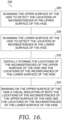
- FIG. 16 depicts a method 226 for detecting inconsistencies on both upper and lower surfaces of a leather hide.
- a block 228 depicts the step of scanning the upper surface of the hide to detect the locations of inconsistencies in the upper surface of the hide.
- a block 230 depicts the step of scanning the lower surface of the hide to detect the locations of inconsistencies in the lower surface of the hide.
- a block 232 depicts the step of digitally storing the locations of the inconsistencies of the upper surface of the hide and the locations of the inconsistencies of the lower surface of the hide.
- a block 234 depicts the step of marking on the upper surface of the hide a visual indication of both the locations of the inconsistencies of the upper surface of the hide and the locations of the inconsistencies of the lower surface of the hide.
- Other steps can include moving the first camera assembly and the second camera assembly around the hide. The camera assemblies can be moved from edge to edge of the hide back and forth, as described herein.
- further step include providing at least one of the first camera assembly and the second camera assembly, a first camera for use with direct lighting and a second camera for use with indirect lighting and alternating scanning between the first camera and the second camera.
Landscapes
- Engineering & Computer Science (AREA)
- Chemical & Material Sciences (AREA)
- Health & Medical Sciences (AREA)
- Life Sciences & Earth Sciences (AREA)
- Physics & Mathematics (AREA)
- General Physics & Mathematics (AREA)
- Analytical Chemistry (AREA)
- Biochemistry (AREA)
- General Health & Medical Sciences (AREA)
- Immunology (AREA)
- Pathology (AREA)
- Medicinal Chemistry (AREA)
- Food Science & Technology (AREA)
- Quality & Reliability (AREA)
- Computer Vision & Pattern Recognition (AREA)
- Theoretical Computer Science (AREA)
- Manufacturing & Machinery (AREA)
- Mechanical Engineering (AREA)
- Organic Chemistry (AREA)
- Investigating Materials By The Use Of Optical Means Adapted For Particular Applications (AREA)
- Length Measuring Devices By Optical Means (AREA)
- Investigating Or Analyzing Materials By The Use Of Ultrasonic Waves (AREA)
- Treatment And Processing Of Natural Fur Or Leather (AREA)
- Treatment Of Fiber Materials (AREA)
Description
- Aspects hereof relate to apparatuses, systems and methods for inspecting leather for defects. More particularly, aspects relate to apparatuses, systems and methods for automatically inspecting leather and indicating the location of inconsistencies on the surface of the leather.
- In the manufacture of articles of clothing, for example, shoes, a leather hide is often uses as a component of the article, for instance a shoe upper. A leather hide oftentimes has a variety of inconsistencies (such as defects) on its upper and its lower surface. Such inconsistencies can include such items as a hole, a scar, a scratch, a wrinkle, a blood vessel, or even dirt. It is desirous to not have any of these inconsistencies present in the portion of the leather hide utilized in the final article, for instance in the upper of a shoe. Such inconsistencies present unsightly interruptions in the smoothness of the leather and decrease the overall appearance of the finished article.
- Document
KR 101 226 892 B1 -
Document DE 102 07 574 A1 describes a projector that projects a light pattern, e.g., grid lines, to an animal skin. The pattern is scanned by a camera placed at some distance from the projector and the image analyzed by a computer that recognizes faults by the distortion of the reflected pattern. The faults are classified by volume and can be marked at a workstation. An Independent claim is also included for the process of identifying faults by these means. The classification can be based on the depth or volume of the fault. Preferred Features: The projector and camera can be traversed on a gantry to cover the whole area. The skin can be carried on a conveyor and held by suction. The outer contour of the skin can also be determined. - Aspects hereof provide an apparatus for detecting inconsistencies on both the upper and the lower surfaces of a leather hide. The apparatus includes a frame capable of supporting the hide. The apparatus also includes a first camera assembly movably coupled to the frame and capable of movement along the upper surface of the hide and a second camera assembly movably coupled to the frame and capable of movement along the lower surface of the hide. A computing device is operatively coupled to the first camera assembly and the second camera assembly so that the first camera assembly detects the locations of inconsistencies in the upper surface of the hide and the second camera assembly detects the locations of inconsistencies in the lower surface of the hide. The computing device digitally stores the locations of the inconsistencies of the upper surface of the hide and the locations of the inconsistencies of the lower surface of the hide.
- Another aspect hereof includes an apparatus for detecting inconsistencies on a surface of a leather hide including a frame capable of supporting the hide. A camera assembly skin can be carried on a conveyor and held by suction. The outer contour of the skin can also be determined.
- The claimed invention is defined by the features set forth in the appended independent claims. Additional embodiments of the claimed invention are defined by the dependent claims.
- The present invention is described in detail herein with reference to the attached drawing figures, wherein:
-
FIG. 1 depicts a top perspective view of a system for inspecting a leather hide, in accordance with the claimed invention; -
FIG. 2 depicts a side elevational view of the system inFIG. 1 , in accordance with the claimed invention; -
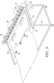
FIG. 3 depicts a top perspective view of a loading cell of the system ofFIG. 1 , in accordance with the claimed invention; -
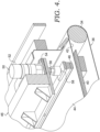
FIG. 4 depicts an enlarged top perspective cross section view of the area designated by the numeral 4 inFIG. 3 ; -
FIG. 5 depicts a top perspective view of the scanning cell of the system ofFIG. 1 , in accordance with the claimed invention; -
FIG. 6 depicts a front perspective view of the camera assemblies and drive mechanisms of the scanning cell ofFIG. 5 ; -
FIG. 7 depicts a top perspective view of the upper and lower camera assemblies of the scanning cell ofFIG. 5 ; -
FIG. 8 depicts a top plan view of the upper camera assembly and drive mechanism inFIG. 7 , parts broken away to reveal details of construction; -
FIG. 9 depicts a top perspective view of the upper camera assembly inFIG. 7 , parts broken away to reveal details of construction; -
FIG. 10 depicts a top perspective view of the marking cell of the system ofFIG. 1 ; -
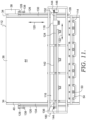
FIG. 11 depicts a top plan view of the loading cell inFIG. 10 ; -
FIG. 12 depicts an enlarged top perspective view of the area designated by thenumeral 12 inFIG. 10 ; -
FIG. 13 depicts a computer monitor showing various inconsistencies as scanned by the camera assembly ofFIG. 7 ; -
FIG. 14 depicts a table showing the various types of inconsistencies (such as defects), their frequency, size, priority and way of marking; -
FIG. 15 depicts an exemplary computing operating environment, such as a programmable logic controller and/or a personal computer, for implementing aspects hereof; and -
FIG. 16 depicts a flow diagram representing a method for detecting inconsistencies on both the upper and lower surfaces of a leather hide, in accordance with the claimed invention. - Articles of clothing and accessories, such as jackets, shoes and purses, are often made of leather. Leather is typically provided to the article manufacturer from a tannery in the form of a hide which is an irregular-shaped planer item from which the article or a portion thereof is cut out. For instance, in the manufacturing of shoes, the upper of the shoe is often made partially of or solely of leather. Whatever the article, such as a shoe, that is manufactured, it is desirous to have a smooth surface on both the inner and outer surfaces of the article, the outer surface to ensure a superior appearance and the inner surface to insure comfort for the wearer. Additionally, if the interior surface of the article, for instance a shoe, is visible to a wearer, unseemly inconsistences (such as defects) are to be avoided. Because the hide is made from the skin of an animal, typically a cow, there are oftentimes many inconsistences (such as defects) in the hide. These defects could include, for instance, but not limited to, holes, scars, scratches, insect bites, wrinkles, blood vessels or even dirt. When cutting out the portions of the hide to use in the article, it is desirous to ensure that none of these defects exist on either the outer surface of the article or the inner surface of the article. Therefore, it is desirous to have a clear indication of where the defects are on both surfaces of the hide so that an appropriate cutting operation can be performed while only having visual access to one of the surfaces.
- Referring to
FIGS. 1 and2 , aleather inspection system 10 for detecting inconsistencies in both anupper surface 12 and alower surface 14 of ahide 16 is depicted. Thehide 16 is typically made of the tanned and treated skin of an animal, such as a cow. Thehide 16 is also typically planer and can have a multitude of irregular shapes depending on a variety of processing techniques. Thehide 16 may have inconsistencies in both itsupper surface 12 and itslower surface 14. One example of inconsistencies may be defects, for instance, but limited to holes, scars, scratches, insect bites, wrinkles, blood vessels or even dirt. - The
inspection system 10 includes aloading cell 18, ascanning cell 20, and a markingcell 22. Theloading cell 18 serves to transport, load and hold thehide 16 for thescanning cell 20. The scanningcell 20 performs the scanning of theupper surface 12 and thelower surface 14 of thehide 16 to automatically detect any inconsistencies in thesurfaces surfaces cell 22 utilizes the stored locations of the inconsistencies of bothsurfaces upper surface 12 of thehide 16. Thus, a worker will have a physical indication on theupper surface 12 of both the inconsistencies in theupper surface 12 and thelower surface 14. The worker can utilize the physical indications of the inconsistencies to cut out a suitable component of an article of manufacture, for instance, but not limited to a shoe upper. It is also contemplated and within the scope of aspects hereof that the stored inconsistencies of both surface 12 and 14 in the computing device may be utilized in an automated cutting operation without any actual physical marking on theupper surface 12. - Referring to
FIGS. 1-4 , theloading cell 18 will be described. First, in order to easily have thehide 16 move through thesystem 10, it was found to be desirous to attach a leadingportion 24 of thehide 16 to aplaner loading jig 26. Theloading jig 26 can be a rectangular sheet of plastic or metal and can have a variety ofdifferent attachment members 28 to secure the leadingportion 24 to thejig 26.Attachment members 28 can pass through thehide 16 in a cutting type manner or may be less intrusive by for instance utilizing magnetic forces. - The
loading cell 18 has aframe 30 that supports aloading conveyer mechanism 32 that is used to pass thehide 16 to thescanning cell 20. Theconveyer mechanism 32 includes a pair ofrollers 34 supporting abelt 36. A first ofrollers 36 is driven by a suitablepowered belt drive 38. Thebelt drive 38 can be powered in any suitable fashion, by for instance, but not limited to, an electric or pneumatic motor. Theframe 30 also has ahorizontal support plate 40 for supporting alower surface 42 of thebelt 36. Anupper surface 44 ofbelt 36 engages thelower surface 14 of thehide 16. Therefore, as thebelt 36 is powered by thebelt drive 38, the engagement between the beltupper surface 44 and the hidelower surface 14 is what moves thehide 16 towards the scanningcell 20. Additionally, theloading jig 26 also engages the beltupper surface 44 and provides additional leading engagement towards the scanningcell 20. Thus, theloading cell 18 provides structure and mechanisms to movehide 16 and the attachedloading jig 26 into the scanningcell 20. - The
loading cell 18 further has aclamp mechanism 46 for periodically clamping thehide 16 between a clampingplate 48 of theclamp mechanism 46 and the beltupper surface 44. This clamping action takes place during the scanning of a portion of thehide 16 that is exposed to thescanning cell 20. More specifically, theconveyer mechanism 32 is actuated to move a portion of thehide 16 into the scanningcell 20. Once an appropriate portion of thehide 16 is in thescanning cell 20, theconveyer mechanism 32 is deactivated and theclamping mechanism 46 is actuated to secure a portion of thehide 16 adjacent the scanningcell 20 entrance to secure thehide 16 during scanning. The clampingplate 48 is movably coupled to a plurality ofactuators 50. Theactuators 50 can be of any suitable type for instance pneumatic or hydraulic cylinders or electrical solenoids. Acylinder 52 of each actuator 50 is secured to amount beam 54 that is suspended above theconveyer mechanism 32 by theframe 30. Apiston 56 of the eachactuator 50 extends through an aperture (not shown) inbeam 54 and is secured at alower end 58 to theclamp plate 48. Thus, as theactuators 50 are activated in such a way as to extendpistons 56, theclamp plate 48 will engage the hideupper surface 12 so as to pinch or clamp thehide 16 between theclamp plate 48 and the beltupper surface 44. Theconveyor mechanism 32 and theclamp mechanism 46 are automatically actuated by a computing device to act in unison with the scanningcell 20 and the markingcell 22 as will be further described herein. - Referring to
FIGS. 1 ,2 , and5-9 , the scanningcell 20 will be described. The scanningcell 20 has asupport frame 60 for supporting an uppertransverse scanning mechanism 62 and a lowertransverse scanning mechanism 64. Theupper scanning mechanism 62 is used to automatically inspect the hideupper surface 12 for inconsistencies (such as defects) and thelower scanning mechanism 64 is used to automatically inspect the hidelower surface 14 for inconsistencies. Theupper scanning mechanism 62 and thelower scanning mechanism 64 can be actuated, such that when theupper scanning mechanism 62 is scanning a portion of the hideupper surface 12, thelower scanning mechanism 64 is simultaneously scanning a portion of the hidelower surface 14 that is directly below the portion being scanned on the hideupper surface 12. As will be further described herein, the synchronization between theupper scanning mechanism 62 and thelower scanning mechanism 64 is accomplished by triggering the image scanning based upon target servo encoder values for theupper scanning mechanism 62 and thelower scanning mechanism 64. Thesupport frame 60 also supports an elongated rectangulartransparent plate 66 which allows the scanning of both the hideupper surface 12 and the hidelower surface 14. More specifically, thetransparent plate 66 supports and engages the hidelower surface 14 when a portion of thehide 16 is in thescanning cell 20. As described herein, thetransparent plate 66 allows thescanning mechanism 64 to inspect the hidelower surface 14 because of its transparent nature. Theplate 66 can be made of any suitable transparent material, for instance glass or plastic. The desirous aspect ofplate 66 is the ability to have lower imaging devices have visual access to the hidelower surface 14. - The
scanning mechanisms scanning mechanism 62 scans in a downward fashion andscanning mechanism 64 scans in an upward fashion. Each ofscanning mechanisms transverse screw actuator 68 for moving an imaging/camera assembly 70 back and forth across a transverse direction of thehide 16. Eachscrew actuator 68 includes ahousing 72 that is supported by theframe 60. Referring toFIG. 8 , eachhousing 72 includes adrive screw 74 which is rotated to effectuate the transverse motion of theimage assembly 70. Thedrive screw 74 is power by asuitable rotary actuator 76. Therotary actuator 76 can be of any suitable type for instance a servomotor, a pneumatic motor, or an electric motor. Although as indicated, any suitable actuator capable of moving theimage assembly 70 could be used. Eachdrive screw 74 is rotatably coupled to amovable carriage 78 via a male/female thread arrangement. More specifically, thedrive screw 74 has a male thread arrangement and thecarriage 78 has an aperture (not shown) with a female thread arrangement. Thus, asrotary actuator 76 is activated,drive screw 74 is rotated and, as a consequence, thecarriage 78 is moved transversely along thedrive screw 74. Connected to thecarriage 78 is a connectingflange 80 for theimage assembly 70. The connectingflange 80 extends through anelongated slot 82 formed on afront surface 84 of thehousing 72. The connectingflange 80 moves with thecarriage 78 as thecarriage 78 is transported along thedrive screw 74 by rotation of thedrive screw 74. Thus, theflange 80 moves back and forth within theslot 82 as thecarriage 78 moves transversely. Theflange 80 is connected on afirst end 86 to an upstanding connectingplate 88 ofimage assembly 70. The connectingplate 88 extends upwardly from abody 90 of theimage assembly 70 inupper scanning mechanism 62. The connectingplate 88 extends downwardly from thebody 90 of theimage assembly 70 in thelower scanning mechanism 64. In this manner, as therespective carriage 78 moves along itsrespective drive screw 74 so does therespective image assembly 70 move transversely with respect to an inspectedhide 16. This transverse movement ofupper scanning mechanism 62 andlower scanning mechanism 64 results in the scanning of the hideupper surface 12 and the hidelower surface 14, respectively. Theimage assembly 70 of theupper scanning mechanism 62 can be synchronized with theimage assembly 70 of thelower scanning mechanism 64, such that when theimage assembly 70 of theupper scanning mechanism 62 is scanning a portion of the hideupper surface 12, theimage assembly 70 of thelower scanning mechanism 64 is simultaneously scanning a portion of the hidelower surface 14 that is directly below the portion being scanned on the hideupper surface 12. The synchronization between theupper image assembly 70 and thelower image assembly 70 is accomplished by triggering therespective image assembly 70 based upon an identical series of target servo values for the respectivetransverse screw actuator 68. In this manner, the upper andlower image assemblies 70 are synchronized to take images of theupper hide surface 12 and thelower hide surface 14 at the same time bases upon an identical set of encoder values stored for each respectivetransverse screw actuator 68 and its associatedrotary actuator 76. As is apparent, in this manner, the amount of time required to scan both the hideupper surface 12 and the hidelower surface 14 is significantly decreased. During the scanning operation, theimage assemblies 70 can move from side to side along the entire length ofscanning mechanisms image assemblies 70 in essence move from one side edge of the scanningcell 20 to the other side edge of the scanningcell 20. However, it may be advantages to increase efficiencies to only have theimage assemblies 70 move back and forth over thehide 16 instead of moving along the entire length of thescanning mechanisms image assemblies 70 would move back and forth from edge to edge of thehide 16 instead of moving back and forth from edge to edge of the scanningcell 20. This can increase the efficiency of the scanning operation by ensuring that theimage assemblies 70 move between the edges of thehide 16 instead between the edges of the scanning cell 20 (where there may not be any portion of thehide 16 present). Thecamera 92 and/or thecamera 94 of the image assemblies 70 (described in detail below) can be used to detect the edges of thehide 16. Eachcamera hide 16 is detected, the directions of theimage assemblies 70 are reversed along theirrespective scanning mechanism cameras 92 and/or 94, there may be others sensors placed on thescanning cell 20 to detect the edges of thehide 16. - Also, as is contemplated, the
image assemblies 70 are not required to move in synchrony. The image assemblies can move in opposite directions or even in the same direction, but not vertically aligned. There may be situations where such a non-synchronous movement is advantages. - Referring to
FIGS. 7-9 , thebody 90 of eachimage assembly 70 supports twocameras camera 92 scans and detects inconsistencies in in the surface of thehide 16 based upon indirect lighting and thecamera 94 detects inconsistencies in the surface of thehide 16 based upon direct lighting. More specifically, it is contemplated that thecamera 92 utilizing indirect lighting will detect eighty to ninety percent of the inconsistences in the hideupper surface 12 or the hidelower surface 14 depending on whether theimage assembly 70 is associated with theupper scanning mechanism 62 or thelower scanning mechanism 64. Still further, thecamera 94 utilizing direct lighting will capture the other ten percent or twenty percent of the inconsistencies in the hideupper surface 12 or the hidelower surface 14 depending on whether theimage assembly 70 is associated with theupper scanning mechanism 62 or thelower scanning mechanism 64. - The indirect lighting of
camera 92 is provided by anindirect lighting source 96. Theindirect lighting source 96 includes a square shapedlighting structure 98 that surrounds aviewing field 100 of theindirect camera 92. Thelighting structure 98 directs light throughlight bars 102 that is not aligned with the downward axial direction of thecamera 92. An axial direction of a camera, such as thecamera 92, is a central line (e.g., axis) extending from the camera in a direction of the field of view of that camera and perpendicular to the camera lens and/or centered in the field of view as captured from the camera. More specifically, the light bars 102 surround theviewing field 100 of thecamera 92 and provides light that is at an angle to the axial direction of thecamera 92. The light bars 102 of theindirect lighting structure 98 are supported by and connected to theimage assembly body 90. Although one type ofindirect lighting source 96 is described above, such description is in no way limiting and, it is in accordance with aspects hereof, that any type of structure that provides indirect light on the hide surface could be used. - The direct lighting of
camera 94 is provided bydirect lighting source 104. Thedirect lighting source 104 includes alight box 106 that surrounds theviewing field 100 of thecamera 94. Thelight box 106 has a two way mirror 108 (shown in phantom) that allows thecamera 94 to visually inspect the hide surfaces 12 or 14 depending on whether thecamera 94 is part of the upper orlower scanning mechanism mirror 108 also reflects a light source (not shown) off its lower surface so that a light shines onsurface camera 94. Thecamera 94 can see throughmirror 108 while themirror 108 also reflects direct lighting on thesurface direct lighting source 104 is described above, such description is in no way limiting and, it is in accordance with aspects hereof, that any type of structure that provides direct light on the hide surface could be used. - Any suitable machine vision camera can be utilized for
cameras cameras cameras camera 92 with its indirectlight source 96 and thecamera 94 with its direct coaxiallight source 104 are operatively coupled to a computing device so that each of the cameras with their lighting sources can be selectively actuated. More specifically, it is contemplated, during a s scanning operation, to alternate actuation between thecamera 92 with indirectlight source 96 andcamera 94 with directlight source 104 so that at any particular moment there is scanning taking place with only indirect light or direct light. This alternating arrangement prevents light pollution between the two different scanning operations, the indirect light scanning and the direct light scanning. - Although only one
image assembly 70 is described for each of theupper scanning mechanism 62 andlower scanning mechanism 64, it is contemplated that there could bemultiple image assemblies 70 associated with each of thescanning mechanism multiple image assemblies 70 could be driven by thetransverse actuator 68 so that different portions of thehide 16 could be scanned bydifferent image assemblies 70. - Referring to
FIGS. 10 -12 , the markingcell 22 will be described. The markingcell 22 has asupport frame 110 having aconveyor mechanism 112 that is similar toconveyor mechanism 32 of theloading cell 18. The difference between the two mechanisms is thatmechanism 112 is used to unload thehide 16 from the scanningcell 20 instead loading the hide. Theconveyor mechanisms conveyer mechanism 112 includes a pair ofrollers 34 supporting abelt 36. A first ofrollers 36 is driven by a suitablepowered belt drive 38. Thebelt drive 38 can be powered in any suitable fashion, by for instance, but not limited to, an electric or pneumatic motor. Theframe 110 also has ahorizontal support plate 40 for supporting alower surface 42 of thebelt 36. Anupper surface 44 ofbelt 36 engages thelower surface 14 of thehide 16. Therefore, as thebelt 36 is powered by thebelt drive 38, the engagement between the beltupper surface 44 and the hidelower surface 14 is what moves thehide 16 away from the scanningcell 20. Additionally, thejig 26 also engages the beltupper surface 44 and provides additional engagement away from the scanningcell 20. Thus, theconveyor mechanism 112 moves thehide 16 and the attachedloading jig 26 away from the scanningcell 20. - The marking
cell 22 further has aclamp mechanism 114 that is similar or identical to clampmechanism 46 of loadingcell 18 and thus, like numerals will be used to designate like parts. The difference between theclamp mechanism 114 and theclamp mechanism 46 is thatclamp mechanism 114 secures thehide 16 during scanning on the exiting side of the scanningcell 20 and theclamp mechanism 46 secures thehide 16 on the entry side of the scanningcell 20. Theclamp mechanism 114 is used for periodically clamping thehide 16 between a clampingplate 48 of theclamp mechanism 114 and the beltupper surface 44. This clamping action takes place during the scanning of a portion of thehide 16 that is exposed to scanningcell 20. More specifically, theconveyer mechanism 112 is actuated to move a portion of thehide 16 away from the scanningcell 20. Once an unscanned portion of thehide 16 is in thescanning cell 20, theconveyer mechanism 112 is deactivated and theclamping mechanism 114 is actuated to secure a portion of thehide 16 adjacent the scanningcell 20 exit to secure thehide 16 during scanning. The clampingplate 48 is movably coupled to a plurality ofactuators 50. Theactuators 50 can be of any type for instance pneumatic or hydraulic cylinders or electrical solenoids. Acylinder 52 of each actuator 50 is secured to amount beam 54 that is suspended above theconveyer mechanism 112 by theframe 110. Apiston 56 of the eachactuator 50 extends through an aperture (not shown) inbeam 54 and is secured at alower end 58 to theclamp plate 48. Thus, as theactuators 50 are activated in such a way as to extendpistons 56, theclamp plate 48 will engage the hideupper surface 12 so as to pinch or clamp thehide 16 between theclamp plate 48 and the beltupper surface 44. Theconveyor mechanism 112 and theclamping mechanism 114 are automatically actuated by a computing device to act in unison with the scanningcell 20 and theloading cell 18 as will be further described herein. - The
support frame 110 also supports a markingdrive mechanism 116 that allows movement of a markingcarriage 118 in two different directs 120 and 122 that are perpendicular to one another as shown inFIG. 11 . More specifically, the markingdrive mechanism 116 allows the positioning of the markingcarriage 118 at any transverse or longitudinal position above thehide 16 after it has been scanned. Thus, once a portion of thehide 16 has been scanned, and that portion is within the markingcell 22, the markingdrive mechanism 116 can be used to position the markingcarriage 118 above the locations of the inconsistencies in the hideupper surface 12 and the hidelower surface 14 and thereafter effectuate a physical marking on the hideupper surface 12 at the locations of both the inconsistencies of the hideupper surface 12 and the hidelower surface 14. - The marking
drive mechanism 116 includes aslide bar 124 that extends transversely across and is slidably coupled to thesupport 110. The slide bar is capable of back and forth movement in thedirection 120. Theslide bar 124 is selectively actuated to any location alongdirection 120 by a pair ofdrive belts 126 rotatably mounted to theframe 110 byrollers 128. More specifically, onedrive belt 126 is located on oneside 130 of theframe 110 and coupled to oneend 132 of theslide bar 124. Theother drive belt 126 is located on theother side 134 of theframe 110 and coupled to theother end 136 of theslide bar 124. Each of thebelts 126 are powered by asuitable belt drive 138 mounted to theframe 110. The belt drives 138 are selectively actuated in unison so as to movebelts 126 in unison. In this manner, movement of theslide bar 124 in thedirection 120 is effectuated as directional force is transferred from thebelts 126 to theends slide bar 124. - The marking
carriage 118 is slidably coupled to theslide bar 124 so that thecarriage 118 can move back and forth along theslide bar 124 in thetransverse direction 122. Thus, thecarriage 118 can be dispersed to any position along theslide bar 124. Thecarriage 118 is powered for movement along theslide bar 124 by thecarriage drive mechanism 140 which is supported by and coupled to theslide bar 124. Thecarriage drive mechanism 140 includes acarriage belt 142 rotatably mounted onrollers 144 and driven by arotary actuator 146. Therotary actuator 146 drives one of therollers 144 such that thecarriage belt 142 can be driven. Therotary actuator 146 can be selectively actuated to move thebelt 142 in thedirection 122. A mid portion of thebelt 142 is coupled to the markingcarriage 118 at aconnection point 148 such that as thebelt 142 moves back and forth in thedirection 122 so does the markingcarriage 118 move back and forth indirection 122. Therotary actuator 146 can be any suitable actuator capable of selective rotary motion, for instance an electric or pneumatic motor. The entirecarriage drive mechanism 140 including thecarriage belt 142, therollers 144, and therotary actuator 146 are mounted to move with theslide bar 124 as it moves in thedirection 120. In this manner, the markingdrive mechanism 116 is capable of being actuated to position the marking carriage at any position above ahide 16 along a coordinate system defined by thedirections - Referring to
FIG. 12 , the markingcarriage 118 will be described. The marking carriage includes abody 150 that is slidably received on theslide bar 124 and operatively coupled to thecarriage drive belt 142. Thebody 150 includes aslot 152 that slidably engages arail 154 of theslide bar 124. It is this slidable engagement between theslot 152 and therail 154 that allows the markingcarriage 118 to move along theslide bar 124. Thebody 150 includes a plurality of markingpen tubes tubes air pressure source 163 coupled thereto. Theair pressure source 163 serves to selectively force the ink within a pen located in a respective tube downwardly towards the hideupper surface 12 to assist the marking action. Theair pressure source 163 can be further used to perform any mechanical action required by a pen located in a respective tube, such as extending or retracing a marking tip. Eachair pressure source 163 can be selectively and individually actuated at any appropriate time to effectuate or enhance the marking ability of a pen contained in one of thetubes FIG. 12 ) to engage and mark the hideupper surface 12 at the locations of the inconsistencies of the hideupper surface 12 and the hidelower surface 14. Thetubes tube 156 can contain a silver marking pen. Still further, for example, thetube 158 can include a yellow pen, thetube 160 can include a red pen, and thetube 162 can include a blue pen. In this manner, for instance, a particular type of defect can be marked with a specific color, as will be more fully described herein. Each of thetubes cartridge 164 that is slidably mounted to thecarriage body 150 for selective actuation in an up and down manner that results in engagement and disengagement of thepen marking tips 166 of pens contained within thetubes upper surface 12. Thetubes respective cartridge 164 by thebrackets 168. Theupper end 170 of eachcartridge 164 is coupled to apiston 172 of alinear actuator 174. Eachactuator 174 also has acylinder 176 mounted to asupport bracket 178 connected to and extending upwardly from thebody 150. Eachpiston 172 extends through an aperture (not shown) in thesupport bracket 178. Eachactuator 174 can be selectively actuated to extend therespective piston 172 resulting in the downward movement of therespective cartridge 164, and thus, resulting in the engagement of the respective pen contained within its respective tube with the hideupper surface 12 for marking. Theactuators 174 can be of any suitable type for instance pneumatic, hydraulic, or electric. - As is apparent, the marking
drive mechanism 116 allows the positioning of the markingcarriage 118 at a wide range of positions above the hideupper surface 12. Still further, the actuation of thevarious tubes carriage 118 allows for engagement of amarking tip 166 of one of the pens contained within one of the tubes. By controlling thedrive mechanism 116 in both thedirection 120 and thedirection 122 while amarking tip 166 of any of the pens located in thetubes upper surface 12, a variety of shapes and lines of all sizes and colors can be marked on the hideupper surface 12 to indicate the locations of inconsistencies in both the hideupper surface 12 and the hidelower surface 14. Examples of shapes, include, without limitation, circles, ovals, squares, rectangles, and/or triangles. Examples of lines, include, without limitation solid lines, dashed lines and/or wavy or curved lines. Thus, the location, size and type of inconsistency can be indicated on the hideupper surface 12 with a particular shape, color or line as drawn by the markingcarriage 118 and the markingdrive mechanism 116. As is apparent, the markingdrive mechanism 116 and the markingcarriage 118 operate independently of, but can also operate in conjunction with, theconveyor mechanism 112. Theconveyer mechanism 112 can be actuated to reposition a portion of thehide 16 so that it is within operational range of the markingdrive mechanism 116 and then thedrive mechanism 116 can perform the drawing operation. The drawing operation of thedrive mechanism 116 can also be actuated at the same time as theconveyor mechanism 112. As will be more fully describe, theconveyor mechanism 112, the markingdrive mechanism 116 and the markingcarriage 118 are all electronically coupled to and controlled by a suitable computing device. - The marking
cell 22 also includes acalibration unit 180 for calibrating the location of thehide 16 on thesupport frame 110 to assist the markingdrive mechanism 116 and the markingcarriage 118 to locate the proper locations to physically mark the inconsistences on the hideupper surface 12. Theunit 180 includes aframe 182 supporting a plurality ofmachine vision cameras 184 and light bars 186. Thecameras 184 and thelight bars 186 are electrically coupled to a suitable computing device so as to assist the correct positioning of the markingcarriage 118 based upon the location of thehide 16 as it exits the scanningcell 18. - Referring to
FIG 13 , awindow 188 on a computer monitor is depicted. Thewindow 188 is divided into foursections first section 190 depicts what the upperindirect lighting camera 92 is seeing and the digital marking of the inconsistencies in the hideupper surface 12. The digital markings are shown as an oval to indicate one type of inconsistency and a square to indicate another type of inconsistency. These digital markings are rendered by a suitable computing device and exist in computer memory. The digital markings can be rendered into actual physical markings on the hideupper surface 12 by the markingdrive mechanism 116 and the markingcarriage 118. The digital markings can also be kept in computer memory and used in an automatic cutting operation, where it is not necessary to physically mark on the hide upper surface. Thesection 192 depicts what an upperdirect lighting camera 94 is seeing. Thissection 192 is not picking up any defects so no digital markings are found in this section. Thesections upper surface 12 and demonstrates how anindirect lighting camera 92 may pick up defects that are not seen by thedirect lighting camera 94. Thesection 194 depicts what the lowerindirect lighting camera 92 is seeing. Thissection 194 is not picking up any defects so no digital markings are found in the section. Thesection 196 depicts what the lowerdirect lighting camera 94 is seeing and the digital markings of the inconsistencies in the hidelower surface 14. The digital markings are shown as a dashed line to indicate one type of inconsistency, a dashed circle to indicate another type of inconsistency, and a square to indicate further type of inconsistency. These digital markings are rendered by a suitable computing device and exist in computer memory. The digital markings can be rendered into actual physical markings on the hideupper surface 12 by the markingdrive mechanism 116 and the markingcarriage 118. The digital markings can also be kept in computer memory and used in an automatic cutting operation, where it is not necessity to physically mark on the hide upper surface. Thesections lower surface 14 and demonstrates howdirect lighting camera 94 may pick up defects that are not seen by theindirect lighting camera 92. -
Fig 14 depicts a table 198 of potential inconsistencies in the form of defects and indicates the priority in detecting, the frequency in which they occur, and their approximate size. The table 198 also reflects how a particular defect may be digitally marked in computer memory or physically marked on the hideupper surface 12. For instance, a square 200 indicates dirt, a hole or a scare; an oval 202 indicates a scratch; asmall square 204 indicates a deep wrinkle; a dashedcircle 206 indicates shallow dirt, a hole or a scare; and a dashed line indicates a blood vessel or shallow wrinkle. -
FIG. 15 depicts an exemplary computing operating environment for implementing aspects hereof as shown and designated generally as computing system ordevice 210. For example, aspects provided herein contemplated using a computing device to control and synchronize all aspects theloading cell 18, the scanningcell 20, and the markingcell 22. More specifically thecomputing device 210 is electrically couple to and controls theconveyor mechanism 32, theclamp mechanism 46, theupper scanning mechanism 62 and its associatedimage assembly 70, thelower scanning mechanism 64 and its associatedimage assembly 70, theconveyor mechanism 112, theclamp mechanism 114, the markingdrive mechanism 116, the markingcarriage 118, and thecalibration unit 180. Thecomputing device 210 is further used to store the locations of the inconsistencies in both the hideupper surface 12 and the hidelower surface 14 and utilize those stored locations to physically mark all inconsistencies from both the hideupper surface 12 and the hidelower surface 14 on the hide upper surface. Thecomputing device 210 is but one example of a suitable computing environment and is not intended to suggest any limitation as to the scope of use or functionality of the invention. Neither should thecomputing device 210 be interpreted as having any dependency or requirement relating to any one or combination of components illustrated. - Aspects herein may be described in the general context of computer code or machine-useable instructions, including computer-executable instructions such as program components, being executed by a computer or other machine, such as a programmable logic controller ("PLC"). Generally, program components, including routines, programs, objects, components, data structures, and the like, refer to code that performs particular tasks or implements particular abstract data types. Aspects hereof may be practiced in a variety of system configurations, including handheld devices, consumer electronics, general-purpose computers, personal computers, specialty computing devices, PLC, etc. Aspects hereof may also be practiced in distributed computing environments where tasks are performed by remote-processing devices that are linked through a communications network.
- With continued reference to
FIG. 15 ,computing device 210 includes abus 212 that directly or indirectly couples the following devices: memory 214, one or more processors 216, one or more presentation components 218, input/output (I/O)ports 220, I/O components 222, and anillustrative power supply 224.Bus 212 represents what may be one or more busses (such as an address bus, data bus, or combination thereof). Although the various blocks ofFIG. 15 are shown with lines for the sake of clarity, in reality, delineating various components is not so clear, and metaphorically, the lines would more accurately be grey and fuzzy. For example, one may consider a presentation component such as a display device to be an I/O component 222. Also, processors have memory. It is recognized that such is the nature of the art, and reiterated that the diagram ofFIG. 15 is merely illustrative of an exemplary computing device that can be used in connection with one or more aspects hereof. Distinction is not made between such categories as "workstation," "server," "laptop," "handheld device," "tablet," "phone," "node," "PLC," etc., as all are contemplated within the scope ofFIG. 15 and refer to "computer" or "computing device." In particular, aspects hereof are contemplated as being performed in whole or in part on one or more components of a distributed computing system. It is contemplated that a distributed computing system may be comprised of processors, networks, and memory that scale to handle as desired level of computing processes at a time. Therefore, it is contemplated that a computing device may also refer to the computing environment of a distributed computing system that dynamically changes with time and/or demand. -
Computing device 210 typically includes a variety of computer-readable media. Computer-readable media can be any available media that can be accessed by computingdevice 210 and includes both volatile and nonvolatile media, removable and nonremovable media. By way of example, and not limitation, computer-readable media may comprise computer-storage media and communication media. Computer-storage media includes both volatile and nonvolatile, removable and non-removable media implemented in any method or technology for storage of information such as computer-readable instructions, data structures, program modules or other data. - Computer-storage media includes RAM, ROM, EEPROM, flash memory or other memory technology, CD-ROM, digital versatile disks (DVD) or other optical disk storage, magnetic cassettes, magnetic tape, magnetic disk storage or other magnetic storage devices. Computer storage media does not comprise a propagated data signal.
- Communication media typically embodies computer-readable instructions, data structures, program modules or other data in a modulated data signal such as a carrier wave or other transport mechanism and includes any information delivery media. The term "modulated data signal" means a signal that has one or more of its characteristics set or changed in such a manner as to encode information in the signal. By way of example, and not limitation, communication media includes wired media such as a wired network or directwired connection, and wireless media such as acoustic, RF, infrared and other wireless media. Combinations of any of the above should also be included within the scope of computer-readable media.
- Memory 214 includes computer-storage media in the form of volatile and/or nonvolatile memory. The memory 214 may be removable, nonremovable, or a combination thereof. Exemplary memory includes non-transitory, solid-state memory, hard drives, optical-disc drives, etc.
Computing device 210 includes one or more processors 216 that read data from various entities such asbus 212, memory 214 or I/O components 222. Presentation component(s) 218 present data indications to a person or other device. Exemplary presentation components 218 include a display device, speaker, printing component, vibrating component, etc. I/O ports 220 allowcomputing device 210 to be logically coupled to other devices including I/O components 222, some of which may be built in. Illustrative I/O components 222 include a microphone, joystick, game pad, satellite dish, scanner, printer, wireless device, etc. -
FIG. 16 depicts amethod 226 for detecting inconsistencies on both upper and lower surfaces of a leather hide. Ablock 228 depicts the step of scanning the upper surface of the hide to detect the locations of inconsistencies in the upper surface of the hide. Ablock 230 depicts the step of scanning the lower surface of the hide to detect the locations of inconsistencies in the lower surface of the hide. Ablock 232 depicts the step of digitally storing the locations of the inconsistencies of the upper surface of the hide and the locations of the inconsistencies of the lower surface of the hide. Ablock 234 depicts the step of marking on the upper surface of the hide a visual indication of both the locations of the inconsistencies of the upper surface of the hide and the locations of the inconsistencies of the lower surface of the hide. Other steps can include moving the first camera assembly and the second camera assembly around the hide. The camera assemblies can be moved from edge to edge of the hide back and forth, as described herein. According to the invention further step include providing at least one of the first camera assembly and the second camera assembly, a first camera for use with direct lighting and a second camera for use with indirect lighting and alternating scanning between the first camera and the second camera.
Claims (14)
- A leather inspection apparatus (10) for detecting inconsistencies on both an upper surface (12) and a lower surface (14) of a leather hide (16), comprising:a frame (30) capable of supporting the leather hide (16);a first camera assembly (62, 70) movably coupled to the frame (30) and capable of movement along the upper surface (12) of the leather hide (16);a second camera assembly (64, 70) movably coupled to the frame (30) and capable of movement along the lower surface (14) of the leather hide (16); anda computing device (210) operatively coupled to the first camera assembly (62, 70) and the second camera assembly (64, 70);wherein the first camera assembly (62, 70) detects the locations of inconsistencies in the upper surface (12) of the leather hide (16) and the second camera assembly (64, 70) detects the locations of inconsistencies in the lower surface (14) of the leather hide (16) and wherein the computing device (210) digitally stores the locations of the inconsistencies of the upper surface (12) of the leather hide (16) and the locations of the inconsistencies of the lower surface (14) of the leather hide (16),characterised in that at least one of the first camera assembly (62, 70) and the second camera assembly (64, 70) includes a first camera (94) and a second camera (92), wherein the first camera (94) detects inconsistencies based on direct lighting and the second camera (92) detects inconsistencies based on indirect lighting.
- The leather inspection apparatus (10) of claim 1 including a marking carriage (118) movably coupled to the frame (30) and operatively coupled to the computing device (210);
wherein the marking carriage (118) provides on the upper surface (12) of the leather hide (16) a visual indication of both the locations of the inconsistencies of the upper surface (12) of the leather hide (16) and the locations of the inconsistencies of the lower surface (14) of the leather hide (16). - The leather inspection apparatus (10) of claim 2, wherein the marking carriage (118) includes more than one marking instrument being capable of providing different types of visual indications on the upper surface (12) of the leather hide (16).
- The leather inspection apparatus (10) of claim 3, wherein each different type of visual indication indicates a type of defect in the leather hide (16).
- The leather inspection apparatus (10) of claim 1, wherein the first camera assembly (62,70) and the second camera assembly (64, 70) are each slidably mounted to the frame (30);
wherein the first camera assembly (62, 70) scans the upper surface (12) of the leather hide (16) in a linear direction and the second camera assembly (64, 70) scans the lower surface (14) of the leather hide (16) in a linear direction. - The leather inspection apparatus (10) of claim 5 further including a conveyer assembly (112) coupled to the frame (30) and for moving the leather hide (16) between the first camera assembly (62, 70) and the second camera assembly (64, 70);
wherein the conveyer assembly (112) is operatively coupled to the computing device (210) so that the computing device (210) controls the first camera assembly (62, 70), the second camera (64, 70) assembly and the conveyer assembly (112) to effectuate a scan of multiple portions of the leather hide (16). - The leather inspection apparatus (10) of claim 6, wherein the conveyer assembly (112) moves the leather hide (16) in a direction perpendicular to the linear direction of the first camera assembly (62, 70) and the linear direction of the second camera assembly (64,70).
- The leather inspection apparatus (10) of claim 2, wherein the marking carriage (112) is slidably coupled to the frame (30) in two different directions perpendicular to one another, so that the computing device (210) controls the marking carriage (112) to provide a suitable visual indication.
- The leather inspection apparatus (10) of claim 8, wherein the visual indication is a circle.
- The leather inspection apparatus (10) of claim 1, wherein the first camera (94) includes a coaxial direct light source (104) aligned with an axis of the first camera and (94) the second camera (92) includes a diffuse light source (96) generally at an angle to an axis of the second camera (92).
- The leather inspection apparatus (10) of claim 10, wherein the first camera (94) with coaxial light source and the second camera (92) with the diffuse light source are actuated by the computing device (210) in an alternating arrangement as at least the first camera assembly (62, 70) moves relative to the leather hide (16).
- A method for detecting inconsistencies on both an upper surface (12) and a lower surface (14) of a leather hide (16), comprising:
moving a first camera assembly (62, 70) and a second camera assembly (64, 70) around a leather hide (19);scanning of the leather hide (16) to detect the locations of inconsistencies in the upper surface (12) of the leather hide (16);scanning the lower surface (14) of the leather hide (16) to detect the locations of inconsistencies in the lower surface (14) of the leather hide (16);digitally storing the locations of the inconsistencies of the upper surface (12) of the leather hide (16) and the locations of the inconsistencies of the lower surface (14) of the leather hide (16),characterised in that at least one of the first camera assembly (62, 70) and the second camera assembly (64, 70) includes a first camera (94) and a second camera (92), wherein the first camera (94) detects inconsistencies based on direct lighting and the second camera (92) detects inconsistencies based on indirect lighting. - The method of claim 12 further comprising; marking on the upper surface (12) of the leather hide (16) a visual indication of both the locations of the inconsistencies of the upper surface (12) of the leather hide (16) and the locations of the inconsistencies of the lower surface (14) of the leather hide (16).
- The method of claim 12 further comprising: alternating scanning between the first camera (94) and the second camera (92).
Priority Applications (1)
| Application Number | Priority Date | Filing Date | Title |
|---|---|---|---|
| EP24194216.8A EP4491748A1 (en) | 2018-05-22 | 2019-05-22 | Leather inspecting system and method for inspecting leather |
Applications Claiming Priority (2)
| Application Number | Priority Date | Filing Date | Title |
|---|---|---|---|
| US201862674730P | 2018-05-22 | 2018-05-22 | |
| PCT/US2019/033566 WO2019226798A1 (en) | 2018-05-22 | 2019-05-22 | Leather inspection system |
Related Child Applications (1)
| Application Number | Title | Priority Date | Filing Date |
|---|---|---|---|
| EP24194216.8A Division EP4491748A1 (en) | 2018-05-22 | 2019-05-22 | Leather inspecting system and method for inspecting leather |
Publications (2)
| Publication Number | Publication Date |
|---|---|
| EP3768867A1 EP3768867A1 (en) | 2021-01-27 |
| EP3768867B1 true EP3768867B1 (en) | 2024-08-21 |
Family
ID=66821470
Family Applications (2)
| Application Number | Title | Priority Date | Filing Date |
|---|---|---|---|
| EP19730045.2A Active EP3768867B1 (en) | 2018-05-22 | 2019-05-22 | Leather inspecting system and method for inspecting leather |
| EP24194216.8A Pending EP4491748A1 (en) | 2018-05-22 | 2019-05-22 | Leather inspecting system and method for inspecting leather |
Family Applications After (1)
| Application Number | Title | Priority Date | Filing Date |
|---|---|---|---|
| EP24194216.8A Pending EP4491748A1 (en) | 2018-05-22 | 2019-05-22 | Leather inspecting system and method for inspecting leather |
Country Status (6)
| Country | Link |
|---|---|
| US (2) | US10955403B2 (en) |
| EP (2) | EP3768867B1 (en) |
| KR (1) | KR102543863B1 (en) |
| CN (2) | CN112218960B (en) |
| TW (2) | TWI721427B (en) |
| WO (1) | WO2019226798A1 (en) |
Families Citing this family (10)
| Publication number | Priority date | Publication date | Assignee | Title |
|---|---|---|---|---|
| TWI721427B (en) * | 2018-05-22 | 2021-03-11 | 荷蘭商耐克創新有限合夥公司 | Leather inspection apparatus and method for detecting inconsistencies on both upper and lower surfaces of hide |
| IT202000008848A1 (en) | 2020-04-24 | 2021-10-24 | Compolab S R L | METHOD AND APPARATUS FOR THE CHARACTERIZATION AND TRACING OF SKINS OR PIECES OF SKINS |
| WO2021240279A1 (en) * | 2020-05-29 | 2021-12-02 | Conceria Pasubio S.P.A. | Method and apparatus for identifying possible surface defects of a leather hide |
| CA3188219A1 (en) | 2020-08-03 | 2022-02-10 | Yifat Bareket | Tracking hide and leather in a supply chain process |
| CN112034149B (en) * | 2020-09-09 | 2021-06-22 | 绍兴市沂风机械有限公司 | Damaged detection repair equipment of leather |
| WO2022053906A1 (en) * | 2020-09-10 | 2022-03-17 | Brevetti Cea Spa | Inspecting machine for leather and inspection method applicable to said machine |
| CN112730444A (en) * | 2020-12-30 | 2021-04-30 | 扬州哈工博视科技有限公司 | Automatic detection device and method for hidden defects of leather |
| IT202200013669A1 (en) * | 2022-06-28 | 2023-12-28 | Cea Brevetti Spa | LEATHER INSPECTION MACHINE |
| TWI828544B (en) | 2023-02-22 | 2024-01-01 | 開必拓數據股份有限公司 | Interactive user feedback system to enhance inspection accuracy of automated visual inspection system |
| IT202300008838A1 (en) * | 2023-05-04 | 2024-11-04 | Aitem S R L | : METHOD FOR ANALYSIS OF SURFACE DEFECTS |
Family Cites Families (29)
| Publication number | Priority date | Publication date | Assignee | Title |
|---|---|---|---|---|
| DE4012462A1 (en) * | 1990-04-19 | 1991-10-24 | Duerkopp System Technik Gmbh | METHOD FOR NESTING NATURAL LEATHER |
| DE4216469A1 (en) * | 1992-05-19 | 1993-11-25 | Diehl Gmbh & Co | Defect classification system for skin to be used to make leather - analyses infrared radiation distribution transmitted through tanned stretched skin in wet-blue state and passed between heat-radiating quartz lamps and CCD or line camera. |
| AUPN800796A0 (en) * | 1996-02-09 | 1996-03-07 | Unisearch Limited | Visual inspection system for leather hide |
| DE19824304A1 (en) * | 1998-05-28 | 1999-12-02 | Maass Ruth | Apparatus for classifying pieces of leather, having a camera to scan the leather on a digitizing bed and a computer to evaluate the data |
| DE10207574B4 (en) * | 2002-02-22 | 2019-05-09 | Wolfgang Bruder | Machining table for flat, pliable body made of leather and method for detecting errors |
| DE102004015110A1 (en) | 2004-03-27 | 2005-10-13 | Texmag Gmbh Vertriebsgesellschaft | Detection apparatus for detecting defects in joints of sheet pieces, has source(s) of electromagnetic non-unidirectional radiations, and one or more sensors that make two-dimensional detection of reflected or refracted radiation |
| US7355700B2 (en) * | 2004-12-10 | 2008-04-08 | International Business Machines Corporation | Automated inspection system and method |
| CN100485371C (en) * | 2005-12-01 | 2009-05-06 | 渤海船舶重工有限责任公司 | Automatic online detection method for defects on upper and lower surfaces during steel plate pretreatment process |
| JP2009115468A (en) * | 2007-11-01 | 2009-05-28 | Midori Hokuyo Kk | Inspection device and inspection method of leather |
| CN201130011Y (en) * | 2007-11-05 | 2008-10-08 | 陆志洪 | Extension type electronic leather measuring machine |
| KR100863700B1 (en) * | 2008-02-18 | 2008-10-15 | 에스엔유 프리시젼 주식회사 | Vision inspection system and inspection method of inspected object using the same |
| WO2011030360A1 (en) * | 2009-09-11 | 2011-03-17 | Camoga S.P.A. | Machine for automatic detection of flaws on pieces made of leather or similar material |
| AT509382B1 (en) * | 2010-01-18 | 2011-12-15 | Wollsdorf Leder Schmidt & Co Gmbh | TEST EQUIPMENT FOR DETERMINING THE QUALITY OF LEATHER |
| WO2012060726A1 (en) * | 2010-11-04 | 2012-05-10 | Couro Azul - Indústria E Comércio De Couros, Sa | Process to detect defects in leather |
| KR101226892B1 (en) * | 2012-08-02 | 2013-02-05 | 주식회사 지백프로 | Tracking system for leather quality |
| WO2014120765A1 (en) * | 2013-01-29 | 2014-08-07 | Gerber Scientific Intternational, Inc. | Leather process automation for die cutting operations |
| DE102013005489B4 (en) * | 2013-04-02 | 2019-06-27 | Capex Invest GmbH | Method and device for the automatic detection of defects in limp bodies |
| KR101550263B1 (en) * | 2014-02-27 | 2015-09-15 | 뉴인텍 주식회사 | Optical inspection apparatus |
| SMT201800358T1 (en) * | 2014-07-10 | 2018-09-13 | Camoga Spa | Device for detection, marking and cutting of leather |
| CN104766314B (en) * | 2015-03-27 | 2018-07-10 | 长园和鹰智能科技有限公司 | Fabric reading machine and fabric read method with flaw mark function |
| BR112017021086B1 (en) * | 2015-04-02 | 2022-12-13 | Erretre S.P.A. | PLAN AND SUPPORT FRAME FOR DRYING AND/OR CONDITIONING OF LEATHER |
| CN105021618A (en) * | 2015-07-22 | 2015-11-04 | 深圳市赛拓工控技术有限公司 | Leather texture detection device |
| CN204789352U (en) * | 2015-07-22 | 2015-11-18 | 深圳市赛拓工控技术有限公司 | Leather texture detection device |
| CN105301009A (en) * | 2015-10-14 | 2016-02-03 | 中国计量学院 | Brake block appearance defect multi-station online detection device and method |
| CN205374331U (en) * | 2016-01-07 | 2016-07-06 | 杭州汉振科技有限公司 | Object surface blemish detection device |
| CN107462520B (en) * | 2017-07-25 | 2023-11-28 | 杭州电子科技大学 | Stainless steel plate online inspection device based on machine vision for limited space |
| CN107238606A (en) * | 2017-07-27 | 2017-10-10 | 苏州珂锐铁电气科技有限公司 | A kind of Tension levelling line strip double-side detecting device |
| CN108037138A (en) * | 2017-12-23 | 2018-05-15 | 陕西科技大学 | A kind of web inspection system and detection method for being used to detect the two-sided defect of paper |
| TWI721427B (en) * | 2018-05-22 | 2021-03-11 | 荷蘭商耐克創新有限合夥公司 | Leather inspection apparatus and method for detecting inconsistencies on both upper and lower surfaces of hide |
-
2019
- 2019-05-20 TW TW108117267A patent/TWI721427B/en active
- 2019-05-20 TW TW110104841A patent/TWI818235B/en not_active IP Right Cessation
- 2019-05-21 US US16/418,774 patent/US10955403B2/en active Active
- 2019-05-22 KR KR1020207033353A patent/KR102543863B1/en active Active
- 2019-05-22 WO PCT/US2019/033566 patent/WO2019226798A1/en not_active Ceased
- 2019-05-22 EP EP19730045.2A patent/EP3768867B1/en active Active
- 2019-05-22 CN CN201980035210.5A patent/CN112218960B/en active Active
- 2019-05-22 CN CN202211108918.9A patent/CN115541858B/en active Active
- 2019-05-22 EP EP24194216.8A patent/EP4491748A1/en active Pending
-
2021
- 2021-03-18 US US17/205,868 patent/US11668694B2/en active Active
Also Published As
| Publication number | Publication date |
|---|---|
| TW202130991A (en) | 2021-08-16 |
| KR20200143483A (en) | 2020-12-23 |
| TWI818235B (en) | 2023-10-11 |
| CN115541858B (en) | 2026-08-04 |
| CN112218960A (en) | 2021-01-12 |
| US20210208126A1 (en) | 2021-07-08 |
| CN115541858A (en) | 2022-12-30 |
| US20190360992A1 (en) | 2019-11-28 |
| US11668694B2 (en) | 2023-06-06 |
| KR102543863B1 (en) | 2023-06-14 |
| TWI721427B (en) | 2021-03-11 |
| CN112218960B (en) | 2022-09-20 |
| US10955403B2 (en) | 2021-03-23 |
| EP3768867A1 (en) | 2021-01-27 |
| WO2019226798A1 (en) | 2019-11-28 |
| TW202006345A (en) | 2020-02-01 |
| EP4491748A1 (en) | 2025-01-15 |
Similar Documents
| Publication | Publication Date | Title |
|---|---|---|
| US11668694B2 (en) | Leather inspection system | |
| US11465928B2 (en) | Glass sheet acquisition and positioning system and associated method for an inline system for measuring the optical characteristics of a glass sheet | |
| CN110595999B (en) | an image acquisition system | |
| CN115078384B (en) | Quick detection device for pits and cracks on surface of stone large plate | |
| TW202303089A (en) | Processing method and processing device for generating cross-sectional image from three-dimensional position information acquired by visual sensor | |
| KR20160114992A (en) | Bin-picking system and method for bin-picking | |
| JP7695787B2 (en) | Tool check device for robot arm, workpiece machining system, tool check program, and tool check method | |
| US20210318251A1 (en) | Auto focus function for vision inspection system | |
| ES2859898T3 (en) | Automation of leather treatment procedure for die cutting operations | |
| CN118787014B (en) | A multi-adaptive intelligent beef cutting method and device | |
| JP6621351B2 (en) | Image processing apparatus and image processing method for laser processing | |
| CN108615232B (en) | Method, device and platform for detecting defects of porcelain layer | |
| GB2385734A (en) | Method and apparatus for imaging, display and cutting of a sheet material | |
| CN116723917B (en) | Tool inspection device for robotic arms, storage device for storing tool inspection programs, and tool inspection method. | |
| KR101873278B1 (en) | Apparatus for inspecting upper shoe and the method thereof | |
| JP2019200134A (en) | Sheet detection method, sheet processing method, sheet detection device, and sheet processing system | |
| CN218340401U (en) | Bottle bottom pattern recognition device | |
| Sun et al. | A low cost 3D acquiring system for mushroom robot based on webcam and line laser | |
| CA3202968C (en) | Tool checking device, tool checking program, and tool checking method for robot arm | |
| AU2023305024A1 (en) | Method and apparatus for automatically grading used terminals | |
| JP2013231143A (en) | Method for manufacturing leather goods and apparatus for manufacturing leather goods | |
| CN110871442B (en) | Detection system | |
| CN108116057B (en) | Ink jet alignment system and ink jet equipment with automatic alignment function | |
| CN121669572A (en) | Method and system for detecting and sorting defects on whole surface of multi-shaped object | |
| KR20210020497A (en) | Apparatus for surface imaging |
Legal Events
| Date | Code | Title | Description |
|---|---|---|---|
| STAA | Information on the status of an ep patent application or granted ep patent |
Free format text: STATUS: UNKNOWN |
|
| STAA | Information on the status of an ep patent application or granted ep patent |
Free format text: STATUS: THE INTERNATIONAL PUBLICATION HAS BEEN MADE |
|
| PUAI | Public reference made under article 153(3) epc to a published international application that has entered the european phase |
Free format text: ORIGINAL CODE: 0009012 |
|
| STAA | Information on the status of an ep patent application or granted ep patent |
Free format text: STATUS: REQUEST FOR EXAMINATION WAS MADE |
|
| 17P | Request for examination filed |
Effective date: 20201022 |
|
| AK | Designated contracting states |
Kind code of ref document: A1 Designated state(s): AL AT BE BG CH CY CZ DE DK EE ES FI FR GB GR HR HU IE IS IT LI LT LU LV MC MK MT NL NO PL PT RO RS SE SI SK SM TR |
|
| AX | Request for extension of the european patent |
Extension state: BA ME |
|
| DAV | Request for validation of the european patent (deleted) | ||
| DAX | Request for extension of the european patent (deleted) | ||
| STAA | Information on the status of an ep patent application or granted ep patent |
Free format text: STATUS: EXAMINATION IS IN PROGRESS |
|
| 17Q | First examination report despatched |
Effective date: 20221028 |
|
| P01 | Opt-out of the competence of the unified patent court (upc) registered |
Effective date: 20230515 |
|
| GRAP | Despatch of communication of intention to grant a patent |
Free format text: ORIGINAL CODE: EPIDOSNIGR1 |
|
| STAA | Information on the status of an ep patent application or granted ep patent |
Free format text: STATUS: GRANT OF PATENT IS INTENDED |
|
| INTG | Intention to grant announced |
Effective date: 20240415 |
|
| GRAS | Grant fee paid |
Free format text: ORIGINAL CODE: EPIDOSNIGR3 |
|
| GRAA | (expected) grant |
Free format text: ORIGINAL CODE: 0009210 |
|
| STAA | Information on the status of an ep patent application or granted ep patent |
Free format text: STATUS: THE PATENT HAS BEEN GRANTED |
|
| AK | Designated contracting states |
Kind code of ref document: B1 Designated state(s): AL AT BE BG CH CY CZ DE DK EE ES FI FR GB GR HR HU IE IS IT LI LT LU LV MC MK MT NL NO PL PT RO RS SE SI SK SM TR |
|
| REG | Reference to a national code |
Ref country code: GB Ref legal event code: FG4D |
|
| REG | Reference to a national code |
Ref country code: CH Ref legal event code: EP |
|
| REG | Reference to a national code |
Ref country code: IE Ref legal event code: FG4D |
|
| REG | Reference to a national code |
Ref country code: DE Ref legal event code: R096 Ref document number: 602019057376 Country of ref document: DE |
|
| REG | Reference to a national code |
Ref country code: LT Ref legal event code: MG9D |
|
| REG | Reference to a national code |
Ref country code: NL Ref legal event code: MP Effective date: 20240821 |
|
| PG25 | Lapsed in a contracting state [announced via postgrant information from national office to epo] |
Ref country code: NO Free format text: LAPSE BECAUSE OF FAILURE TO SUBMIT A TRANSLATION OF THE DESCRIPTION OR TO PAY THE FEE WITHIN THE PRESCRIBED TIME-LIMIT Effective date: 20241121 |
|
| REG | Reference to a national code |
Ref country code: AT Ref legal event code: MK05 Ref document number: 1715537 Country of ref document: AT Kind code of ref document: T Effective date: 20240821 |
|
| PG25 | Lapsed in a contracting state [announced via postgrant information from national office to epo] |
Ref country code: NL Free format text: LAPSE BECAUSE OF FAILURE TO SUBMIT A TRANSLATION OF THE DESCRIPTION OR TO PAY THE FEE WITHIN THE PRESCRIBED TIME-LIMIT Effective date: 20240821 Ref country code: FI Free format text: LAPSE BECAUSE OF FAILURE TO SUBMIT A TRANSLATION OF THE DESCRIPTION OR TO PAY THE FEE WITHIN THE PRESCRIBED TIME-LIMIT Effective date: 20240821 Ref country code: GR Free format text: LAPSE BECAUSE OF FAILURE TO SUBMIT A TRANSLATION OF THE DESCRIPTION OR TO PAY THE FEE WITHIN THE PRESCRIBED TIME-LIMIT Effective date: 20241122 Ref country code: PL Free format text: LAPSE BECAUSE OF FAILURE TO SUBMIT A TRANSLATION OF THE DESCRIPTION OR TO PAY THE FEE WITHIN THE PRESCRIBED TIME-LIMIT Effective date: 20240821 Ref country code: PT Free format text: LAPSE BECAUSE OF FAILURE TO SUBMIT A TRANSLATION OF THE DESCRIPTION OR TO PAY THE FEE WITHIN THE PRESCRIBED TIME-LIMIT Effective date: 20241223 |
|
| PG25 | Lapsed in a contracting state [announced via postgrant information from national office to epo] |
Ref country code: BG Free format text: LAPSE BECAUSE OF FAILURE TO SUBMIT A TRANSLATION OF THE DESCRIPTION OR TO PAY THE FEE WITHIN THE PRESCRIBED TIME-LIMIT Effective date: 20240821 |
|
| PG25 | Lapsed in a contracting state [announced via postgrant information from national office to epo] |
Ref country code: LV Free format text: LAPSE BECAUSE OF FAILURE TO SUBMIT A TRANSLATION OF THE DESCRIPTION OR TO PAY THE FEE WITHIN THE PRESCRIBED TIME-LIMIT Effective date: 20240821 |
|
| PG25 | Lapsed in a contracting state [announced via postgrant information from national office to epo] |
Ref country code: IS Free format text: LAPSE BECAUSE OF FAILURE TO SUBMIT A TRANSLATION OF THE DESCRIPTION OR TO PAY THE FEE WITHIN THE PRESCRIBED TIME-LIMIT Effective date: 20241221 Ref country code: AT Free format text: LAPSE BECAUSE OF FAILURE TO SUBMIT A TRANSLATION OF THE DESCRIPTION OR TO PAY THE FEE WITHIN THE PRESCRIBED TIME-LIMIT Effective date: 20240821 |
|
| PG25 | Lapsed in a contracting state [announced via postgrant information from national office to epo] |
Ref country code: HR Free format text: LAPSE BECAUSE OF FAILURE TO SUBMIT A TRANSLATION OF THE DESCRIPTION OR TO PAY THE FEE WITHIN THE PRESCRIBED TIME-LIMIT Effective date: 20240821 |
|
| PG25 | Lapsed in a contracting state [announced via postgrant information from national office to epo] |
Ref country code: ES Free format text: LAPSE BECAUSE OF FAILURE TO SUBMIT A TRANSLATION OF THE DESCRIPTION OR TO PAY THE FEE WITHIN THE PRESCRIBED TIME-LIMIT Effective date: 20240821 Ref country code: RS Free format text: LAPSE BECAUSE OF FAILURE TO SUBMIT A TRANSLATION OF THE DESCRIPTION OR TO PAY THE FEE WITHIN THE PRESCRIBED TIME-LIMIT Effective date: 20241121 |
|
| PG25 | Lapsed in a contracting state [announced via postgrant information from national office to epo] |
Ref country code: RS Free format text: LAPSE BECAUSE OF FAILURE TO SUBMIT A TRANSLATION OF THE DESCRIPTION OR TO PAY THE FEE WITHIN THE PRESCRIBED TIME-LIMIT Effective date: 20241121 Ref country code: PT Free format text: LAPSE BECAUSE OF FAILURE TO SUBMIT A TRANSLATION OF THE DESCRIPTION OR TO PAY THE FEE WITHIN THE PRESCRIBED TIME-LIMIT Effective date: 20241223 Ref country code: PL Free format text: LAPSE BECAUSE OF FAILURE TO SUBMIT A TRANSLATION OF THE DESCRIPTION OR TO PAY THE FEE WITHIN THE PRESCRIBED TIME-LIMIT Effective date: 20240821 Ref country code: NO Free format text: LAPSE BECAUSE OF FAILURE TO SUBMIT A TRANSLATION OF THE DESCRIPTION OR TO PAY THE FEE WITHIN THE PRESCRIBED TIME-LIMIT Effective date: 20241121 Ref country code: NL Free format text: LAPSE BECAUSE OF FAILURE TO SUBMIT A TRANSLATION OF THE DESCRIPTION OR TO PAY THE FEE WITHIN THE PRESCRIBED TIME-LIMIT Effective date: 20240821 Ref country code: LV Free format text: LAPSE BECAUSE OF FAILURE TO SUBMIT A TRANSLATION OF THE DESCRIPTION OR TO PAY THE FEE WITHIN THE PRESCRIBED TIME-LIMIT Effective date: 20240821 Ref country code: IS Free format text: LAPSE BECAUSE OF FAILURE TO SUBMIT A TRANSLATION OF THE DESCRIPTION OR TO PAY THE FEE WITHIN THE PRESCRIBED TIME-LIMIT Effective date: 20241221 Ref country code: HR Free format text: LAPSE BECAUSE OF FAILURE TO SUBMIT A TRANSLATION OF THE DESCRIPTION OR TO PAY THE FEE WITHIN THE PRESCRIBED TIME-LIMIT Effective date: 20240821 Ref country code: GR Free format text: LAPSE BECAUSE OF FAILURE TO SUBMIT A TRANSLATION OF THE DESCRIPTION OR TO PAY THE FEE WITHIN THE PRESCRIBED TIME-LIMIT Effective date: 20241122 Ref country code: FI Free format text: LAPSE BECAUSE OF FAILURE TO SUBMIT A TRANSLATION OF THE DESCRIPTION OR TO PAY THE FEE WITHIN THE PRESCRIBED TIME-LIMIT Effective date: 20240821 Ref country code: ES Free format text: LAPSE BECAUSE OF FAILURE TO SUBMIT A TRANSLATION OF THE DESCRIPTION OR TO PAY THE FEE WITHIN THE PRESCRIBED TIME-LIMIT Effective date: 20240821 Ref country code: BG Free format text: LAPSE BECAUSE OF FAILURE TO SUBMIT A TRANSLATION OF THE DESCRIPTION OR TO PAY THE FEE WITHIN THE PRESCRIBED TIME-LIMIT Effective date: 20240821 Ref country code: AT Free format text: LAPSE BECAUSE OF FAILURE TO SUBMIT A TRANSLATION OF THE DESCRIPTION OR TO PAY THE FEE WITHIN THE PRESCRIBED TIME-LIMIT Effective date: 20240821 |
|
| PG25 | Lapsed in a contracting state [announced via postgrant information from national office to epo] |
Ref country code: DK Free format text: LAPSE BECAUSE OF FAILURE TO SUBMIT A TRANSLATION OF THE DESCRIPTION OR TO PAY THE FEE WITHIN THE PRESCRIBED TIME-LIMIT Effective date: 20240821 Ref country code: SM Free format text: LAPSE BECAUSE OF FAILURE TO SUBMIT A TRANSLATION OF THE DESCRIPTION OR TO PAY THE FEE WITHIN THE PRESCRIBED TIME-LIMIT Effective date: 20240821 Ref country code: RO Free format text: LAPSE BECAUSE OF FAILURE TO SUBMIT A TRANSLATION OF THE DESCRIPTION OR TO PAY THE FEE WITHIN THE PRESCRIBED TIME-LIMIT Effective date: 20240821 |
|
| PG25 | Lapsed in a contracting state [announced via postgrant information from national office to epo] |
Ref country code: EE Free format text: LAPSE BECAUSE OF FAILURE TO SUBMIT A TRANSLATION OF THE DESCRIPTION OR TO PAY THE FEE WITHIN THE PRESCRIBED TIME-LIMIT Effective date: 20240821 |
|
| PG25 | Lapsed in a contracting state [announced via postgrant information from national office to epo] |
Ref country code: CZ Free format text: LAPSE BECAUSE OF FAILURE TO SUBMIT A TRANSLATION OF THE DESCRIPTION OR TO PAY THE FEE WITHIN THE PRESCRIBED TIME-LIMIT Effective date: 20240821 |
|
| PG25 | Lapsed in a contracting state [announced via postgrant information from national office to epo] |
Ref country code: SK Free format text: LAPSE BECAUSE OF FAILURE TO SUBMIT A TRANSLATION OF THE DESCRIPTION OR TO PAY THE FEE WITHIN THE PRESCRIBED TIME-LIMIT Effective date: 20240821 Ref country code: IT Free format text: LAPSE BECAUSE OF FAILURE TO SUBMIT A TRANSLATION OF THE DESCRIPTION OR TO PAY THE FEE WITHIN THE PRESCRIBED TIME-LIMIT Effective date: 20240821 |
|
| REG | Reference to a national code |
Ref country code: DE Ref legal event code: R097 Ref document number: 602019057376 Country of ref document: DE |
|
| PLBE | No opposition filed within time limit |
Free format text: ORIGINAL CODE: 0009261 |
|
| STAA | Information on the status of an ep patent application or granted ep patent |
Free format text: STATUS: NO OPPOSITION FILED WITHIN TIME LIMIT |
|
| 26N | No opposition filed |
Effective date: 20250522 |
|
| PG25 | Lapsed in a contracting state [announced via postgrant information from national office to epo] |
Ref country code: SE Free format text: LAPSE BECAUSE OF FAILURE TO SUBMIT A TRANSLATION OF THE DESCRIPTION OR TO PAY THE FEE WITHIN THE PRESCRIBED TIME-LIMIT Effective date: 20240821 |
|
| REG | Reference to a national code |
Ref country code: CH Ref legal event code: H13 Free format text: ST27 STATUS EVENT CODE: U-0-0-H10-H13 (AS PROVIDED BY THE NATIONAL OFFICE) Effective date: 20251223 |
|
| PG25 | Lapsed in a contracting state [announced via postgrant information from national office to epo] |
Ref country code: LU Free format text: LAPSE BECAUSE OF NON-PAYMENT OF DUE FEES Effective date: 20250522 |
|
| PG25 | Lapsed in a contracting state [announced via postgrant information from national office to epo] |
Ref country code: CH Free format text: LAPSE BECAUSE OF NON-PAYMENT OF DUE FEES Effective date: 20250531 |
|
| REG | Reference to a national code |
Ref country code: BE Ref legal event code: MM Effective date: 20250531 |
|
| PG25 | Lapsed in a contracting state [announced via postgrant information from national office to epo] |
Ref country code: MC Free format text: LAPSE BECAUSE OF FAILURE TO SUBMIT A TRANSLATION OF THE DESCRIPTION OR TO PAY THE FEE WITHIN THE PRESCRIBED TIME-LIMIT Effective date: 20240821 |
|
| PGFP | Annual fee paid to national office [announced via postgrant information from national office to epo] |
Ref country code: GB Payment date: 20260316 Year of fee payment: 8 |
|
| PG25 | Lapsed in a contracting state [announced via postgrant information from national office to epo] |
Ref country code: IE Free format text: LAPSE BECAUSE OF NON-PAYMENT OF DUE FEES Effective date: 20250522 |
|
| PG25 | Lapsed in a contracting state [announced via postgrant information from national office to epo] |
Ref country code: BE Free format text: LAPSE BECAUSE OF NON-PAYMENT OF DUE FEES Effective date: 20250531 |
|
| PG25 | Lapsed in a contracting state [announced via postgrant information from national office to epo] |
Ref country code: LT Free format text: LAPSE BECAUSE OF FAILURE TO SUBMIT A TRANSLATION OF THE DESCRIPTION OR TO PAY THE FEE WITHIN THE PRESCRIBED TIME-LIMIT Effective date: 20240821 |
|
| PGFP | Annual fee paid to national office [announced via postgrant information from national office to epo] |
Ref country code: DE Payment date: 20260324 Year of fee payment: 8 |
|
| PGFP | Annual fee paid to national office [announced via postgrant information from national office to epo] |
Ref country code: FR Payment date: 20260401 Year of fee payment: 8 |
|
| PG25 | Lapsed in a contracting state [announced via postgrant information from national office to epo] |
Ref country code: CY Free format text: LAPSE BECAUSE OF FAILURE TO SUBMIT A TRANSLATION OF THE DESCRIPTION OR TO PAY THE FEE WITHIN THE PRESCRIBED TIME-LIMIT Effective date: 20240821 |