EP3768801B1 - Turbomachine chemical reactor and method for cracking hydrocarbons - Google Patents
Turbomachine chemical reactor and method for cracking hydrocarbons Download PDFInfo
- Publication number
- EP3768801B1 EP3768801B1 EP18730544.6A EP18730544A EP3768801B1 EP 3768801 B1 EP3768801 B1 EP 3768801B1 EP 18730544 A EP18730544 A EP 18730544A EP 3768801 B1 EP3768801 B1 EP 3768801B1
- Authority
- EP
- European Patent Office
- Prior art keywords
- process fluid
- impeller
- housing
- diffuser
- axial
- Prior art date
- Legal status (The legal status is an assumption and is not a legal conclusion. Google has not performed a legal analysis and makes no representation as to the accuracy of the status listed.)
- Active
Links
Images




Classifications
-
- B—PERFORMING OPERATIONS; TRANSPORTING
- B01—PHYSICAL OR CHEMICAL PROCESSES OR APPARATUS IN GENERAL
- B01J—CHEMICAL OR PHYSICAL PROCESSES, e.g. CATALYSIS OR COLLOID CHEMISTRY; THEIR RELEVANT APPARATUS
- B01J19/00—Chemical, physical or physico-chemical processes in general; Their relevant apparatus
- B01J19/0053—Details of the reactor
- B01J19/0066—Stirrers
-
- C—CHEMISTRY; METALLURGY
- C10—PETROLEUM, GAS OR COKE INDUSTRIES; TECHNICAL GASES CONTAINING CARBON MONOXIDE; FUELS; LUBRICANTS; PEAT
- C10G—CRACKING HYDROCARBON OILS; PRODUCTION OF LIQUID HYDROCARBON MIXTURES, e.g. BY DESTRUCTIVE HYDROGENATION, OLIGOMERISATION, POLYMERISATION; RECOVERY OF HYDROCARBON OILS FROM OIL-SHALE, OIL-SAND, OR GASES; REFINING MIXTURES MAINLY CONSISTING OF HYDROCARBONS; REFORMING OF NAPHTHA; MINERAL WAXES
- C10G9/00—Thermal non-catalytic cracking, in the absence of hydrogen, of hydrocarbon oils
-
- B—PERFORMING OPERATIONS; TRANSPORTING
- B01—PHYSICAL OR CHEMICAL PROCESSES OR APPARATUS IN GENERAL
- B01J—CHEMICAL OR PHYSICAL PROCESSES, e.g. CATALYSIS OR COLLOID CHEMISTRY; THEIR RELEVANT APPARATUS
- B01J19/00—Chemical, physical or physico-chemical processes in general; Their relevant apparatus
- B01J19/0053—Details of the reactor
- B01J19/006—Baffles
-
- B—PERFORMING OPERATIONS; TRANSPORTING
- B01—PHYSICAL OR CHEMICAL PROCESSES OR APPARATUS IN GENERAL
- B01J—CHEMICAL OR PHYSICAL PROCESSES, e.g. CATALYSIS OR COLLOID CHEMISTRY; THEIR RELEVANT APPARATUS
- B01J19/00—Chemical, physical or physico-chemical processes in general; Their relevant apparatus
- B01J19/008—Processes for carrying out reactions under cavitation conditions
-
- B—PERFORMING OPERATIONS; TRANSPORTING
- B01—PHYSICAL OR CHEMICAL PROCESSES OR APPARATUS IN GENERAL
- B01J—CHEMICAL OR PHYSICAL PROCESSES, e.g. CATALYSIS OR COLLOID CHEMISTRY; THEIR RELEVANT APPARATUS
- B01J19/00—Chemical, physical or physico-chemical processes in general; Their relevant apparatus
- B01J19/08—Processes employing the direct application of electric or wave energy, or particle radiation; Apparatus therefor
- B01J19/10—Processes employing the direct application of electric or wave energy, or particle radiation; Apparatus therefor employing sonic or ultrasonic vibrations
-
- B—PERFORMING OPERATIONS; TRANSPORTING
- B01—PHYSICAL OR CHEMICAL PROCESSES OR APPARATUS IN GENERAL
- B01J—CHEMICAL OR PHYSICAL PROCESSES, e.g. CATALYSIS OR COLLOID CHEMISTRY; THEIR RELEVANT APPARATUS
- B01J19/00—Chemical, physical or physico-chemical processes in general; Their relevant apparatus
- B01J19/18—Stationary reactors having moving elements inside
- B01J19/1806—Stationary reactors having moving elements inside resulting in a turbulent flow of the reactants, such as in centrifugal-type reactors, or having a high Reynolds-number
-
- B—PERFORMING OPERATIONS; TRANSPORTING
- B01—PHYSICAL OR CHEMICAL PROCESSES OR APPARATUS IN GENERAL
- B01J—CHEMICAL OR PHYSICAL PROCESSES, e.g. CATALYSIS OR COLLOID CHEMISTRY; THEIR RELEVANT APPARATUS
- B01J19/00—Chemical, physical or physico-chemical processes in general; Their relevant apparatus
- B01J19/18—Stationary reactors having moving elements inside
- B01J19/1812—Tubular reactors
-
- B—PERFORMING OPERATIONS; TRANSPORTING
- B01—PHYSICAL OR CHEMICAL PROCESSES OR APPARATUS IN GENERAL
- B01J—CHEMICAL OR PHYSICAL PROCESSES, e.g. CATALYSIS OR COLLOID CHEMISTRY; THEIR RELEVANT APPARATUS
- B01J19/00—Chemical, physical or physico-chemical processes in general; Their relevant apparatus
- B01J19/18—Stationary reactors having moving elements inside
- B01J19/1862—Stationary reactors having moving elements inside placed in series
-
- B—PERFORMING OPERATIONS; TRANSPORTING
- B01—PHYSICAL OR CHEMICAL PROCESSES OR APPARATUS IN GENERAL
- B01J—CHEMICAL OR PHYSICAL PROCESSES, e.g. CATALYSIS OR COLLOID CHEMISTRY; THEIR RELEVANT APPARATUS
- B01J3/00—Processes of utilising sub-atmospheric or super-atmospheric pressure to effect chemical or physical change of matter; Apparatus therefor
- B01J3/06—Processes using ultra-high pressure, e.g. for the formation of diamonds; Apparatus therefor, e.g. moulds or dies
- B01J3/08—Application of shock waves for chemical reactions or for modifying the crystal structure of substances
-
- B—PERFORMING OPERATIONS; TRANSPORTING
- B01—PHYSICAL OR CHEMICAL PROCESSES OR APPARATUS IN GENERAL
- B01J—CHEMICAL OR PHYSICAL PROCESSES, e.g. CATALYSIS OR COLLOID CHEMISTRY; THEIR RELEVANT APPARATUS
- B01J6/00—Heat treatments such as Calcining; Fusing ; Pyrolysis
- B01J6/008—Pyrolysis reactions
-
- F—MECHANICAL ENGINEERING; LIGHTING; HEATING; WEAPONS; BLASTING
- F01—MACHINES OR ENGINES IN GENERAL; ENGINE PLANTS IN GENERAL; STEAM ENGINES
- F01D—NON-POSITIVE DISPLACEMENT MACHINES OR ENGINES, e.g. STEAM TURBINES
- F01D1/00—Non-positive-displacement machines or engines, e.g. steam turbines
- F01D1/02—Non-positive-displacement machines or engines, e.g. steam turbines with stationary working-fluid guiding means and bladed or like rotor, e.g. multi-bladed impulse steam turbines
-
- B—PERFORMING OPERATIONS; TRANSPORTING
- B01—PHYSICAL OR CHEMICAL PROCESSES OR APPARATUS IN GENERAL
- B01J—CHEMICAL OR PHYSICAL PROCESSES, e.g. CATALYSIS OR COLLOID CHEMISTRY; THEIR RELEVANT APPARATUS
- B01J2219/00—Chemical, physical or physico-chemical processes in general; Their relevant apparatus
- B01J2219/00002—Chemical plants
- B01J2219/00027—Process aspects
- B01J2219/0004—Processes in series
Definitions
- the invention relates to chemical reactors and methods for cracking hydrocarbons in a process fluid. More particularly, the invention relates to turbomachine chemical reactors and methods for cracking hydrocarbons.
- Oil refineries and petrochemical plants fraction or "crack" heavier molecular weight (MW) hydrocarbons.
- the lighter molecular weight hydrocarbons are used in the petrochemical industry as feedstock for production of other chemical compounds.
- pyrolysis-cracking processes application of heat and pressure in furnace-type, chemical reactors, in low oxygen environments, fractionalizes heavier MW hydrocarbons into various lighter MW olefins, such as ethylene, without causing combustion.
- the heavier MW hydrocarbon is entrained in heated steam.
- the steam- and hydrocarbon-containing process fluid flows through heat exchangers of the chemical reactor. Imparted temperature and residence time of the process fluid within heat exchangers are controlled to fracture the entrained hydrocarbons to the desired output, lower MW hydrocarbons.
- a process fluid comprising hydrocarbon and steam mixture is heated from 1220 °F to 1545 °F in less than 400 milliseconds (MS), in a furnace-type chemical reactor.
- MS milliseconds
- the rate at which the heating is done and subsequently quenched (to halt further chemical reactions) is important for the production of the desired blend of hydrocarbons.
- Oxygen must not be present during the heating process, in order to avoid hydrocarbon combustion.
- the reaction process in the furnace-type chemical reactor requires large heat input and relatively slow mass flow rate of the process fluid.
- ethylene production plants employ multiple, parallel pyrolysis reactors, each requiring large thermal energy inputs.
- WO 2016/001476 A1 describes a shock wave reactor for thermal cracking of hydrocarbon-containing feedstock, comprising a casing wherein a duct is formed with inlet and outlet; a rotor the periphery of which contains an axial-flow blade cascade; wherein the casing substantially encloses the periphery of the rotor and a number of stationary vane cascades inside the duct, and further wherein the cascades are configured to direct feedstock containing process stream to repeatedly pass said cascades in accordance with helical trajectory while propagating within the duct between the inlet and outlet and to generate stationary shock-waves to heat the feedstock.
- EP 0 349 051 A1 describes a mixed-type compressor where each compression stage comprises a main impeller with a diameter increasing in the upstream-downstream direction at the input and at least one fixed rectifier at the output.
- An additional movable impeller is fitted between the main impeller and the fixed rectifier, said impeller being integral in rotation with the main impeller and of the axial vane type with a higher camber at the top than at the bottom so as to reduce the radial gradient of the total flow pressure between the input and the output of said vanes.
- Exemplary embodiments of chemical reactors and methods described herein crack hydrocarbons in process fluids by accelerating the process fluid in a to a velocity greater than Mach 1 with an axial impulse impeller and generating a shock wave in the process fluid by decelerating it in a static diffuser having diverging diffuser passages. Cracking occurs in a single stage, at faster reaction rates and less energy input than traditional pyrolysis-type chemical reactors. Increased mass flow rate afforded by the present invention embodiments, compared to traditional pyrolysis-type chemical reactors and processes, increases production output with less plant equipment capital spending along with the lower energy usage.
- the housing of the turbomachine chemical reactor has an annular housing passage, which defines a unidirectional, axial flow path from a housing inlet to a housing exit.
- a rotating, axial impulse impeller imparts energy to and discharges the process fluid at a velocity greater Mach 1.
- a static annular diffuser having diverging diffuser passages, is in the annular housing passage, oriented between the axial impulse impeller and the exit of the housing. The diffuser passages are configured to decelerate process fluid therein, discharged from the impeller blades, to a speed less than Mach 1.
- the turbomachine chemical reactor has multiple successive stages of one or more axial impulse impellers, paired with a diverging passage, static diffuser.
- Each chemical reactor stage cracks hydrocarbons in the process fluid in a single, unidirectional flow path from its inlet to its outlet, without recirculating the process fluid in the opposite direction for another pass through the same stage.
- the unidirectional flow path facilitates cracking in a relatively short, large cross-sectional, annular flow path.
- hydrocarbons are cracked in a single stage in ten milliseconds (10 MS) or less, with high mass flow rates.
- successive stages incorporating the impulse impeller(s) and a paired, diverging-type static diffuser crack additional hydrocarbons by successively raising process fluid temperature in each stage.
- a chemical reactor for cracking hydrocarbons in a process fluid comprises a housing having: a housing inlet; a housing exit; and an annular housing passage, which defines a unidirectional, axial flow path from the housing inlet to the housing exit, for receiving and cracking hydrocarbon in a process fluid therein; a rotary shaft, in the housing, circumscribed by the annular housing passage, for coupling to a shaft-rotating power source, the rotary shaft defining a shaft centerline axis that is in fixed orientation in the housing and congruent with its axis of rotation; a first axial impulse impeller and a second axial impulse impeller commonly mounted about the rotary shaft within the annular housing passage and in fluid communication with process fluid flowing between the inlet and exit of the housing, the first and second axial impulse impellers axially spaced from one another, with trailing edges of the first axial impulse impeller facing leading edges of the second axial impulse impeller; a row of stationary turning bucket vanes interposed
- a method for cracking hydrocarbons in a process fluid comprises: providing a chemical reactor having: a housing having: a shaft centerline axis that is in fixed orientation in the housing; a housing inlet; a housing exit; and an annular housing passage defining a unidirectional, axial flow path for the process fluid from the housing inlet to the housing exit; a first axial impulse impeller and a second axial impulse impeller commonly mounted about the rotary shaft within the annular housing passage to be rotatively driven about an impeller axis of rotation that is congruent with the shaft centerline axis, the first and second axial impulse impellers axially spaced from one another, each impeller having: an impeller hub with an axial length extending axially along the shaft centerline axis of the rotary shaft; a row of a plurality of impeller blades projecting outwardly from the impeller hub, each of the impeller blades respectively having: a leading edge facing the housing inlet,
- Exemplary method and apparatus embodiments of the invention crack or fractionalize hydrocarbons in process fluids, such as hydrocarbons entrained in steam.
- Chemical reactors and methods described in detail herein crack hydrocarbons in a turbomachine chemical reactor, by accelerating the process fluid in a to a velocity greater than Mach 1 with an axial impulse impeller and generating a shock wave in the process fluid by decelerating it in a static diffuser having diverging diffuser passages.
- static pressure of the process fluid remains relatively constant (e.g., within plus or minus ten percent) as it passes through the impulse impeller(s), but rises downstream of the shockwave.
- the temperature increase through a single stage is greater than ten percent.
- the process fluid passes through the single stage in 10 MS or less, compared to hundreds of milliseconds in known pyrolysis-type reactors.
- Faster mass flow rates in the chemical reactors of the present invention increase production output.
- external heat is not applied to the process fluid in the chemical reactors of the present invention, in order to initiate or maintain the cracking chemical reaction. Elimination of external heating for operating the presently described, a turbomachine chemical reactor, as otherwise required in pyrolysis-type reactors, reduces energy expenditure.
- the turbomachine chemical reactor or a sequential chain of such reactors, has multiple successive stages of two or more axial impulse impellers, paired with a diverging passage, static diffuser. Successive stages crack additional hydrocarbons by successively raising temperature of the flowing process fluid.
- respective, multiple stages share a common housing, or are in separate, sequential housings, or they are in a combination of separate and common housings in a common feedstock line.
- one or more stages in a first reactor function as a preheater of the process fluid, before its flow into a downstream reactor.
- quenching zones are incorporated in chemical reactors downstream of an impeller.
- quenching zone embodiments introduce coolant fluid into the process fluid, in order to stabilize temperature of the process fluid.
- Other quenching zones introduce anti-fouling fluid into the process fluid, in order to inhibit fouling within the diffuser passages.
- Yet other quenching zones introduce both cooling and anti-fouling fluid into the process fluid.
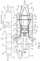
- FIGs. 1 and 2 show a chemical reactor 10, for cracking hydrocarbon in a process fluid.
- the chemical reactor 10 is a turbomachine-type chemical reactor, including a housing 20 having a housing inlet 22, a housing exit 24.
- the housing inlet 22 has a radial orientation, but in other embodiments, it has an axial configuration.
- the housing exit 24 has an axial orientation, but in other embodiments, it has a radial configuration. Any combination of radial or axial inlets and exits for respective inflow or outflow of process fluids are utilized in chemical reactors disclosed herein.
- the housing 20 defines an annular housing passage 26, within the circumferential confines of a shroud wall 28.
- the housing passage 26 defines a unidirectional, axial flow path F from the housing inlet 22 to the housing exit 24, for receiving and cracking hydrocarbon in a process fluid that flows through the axial flow path.
- a process flow diagram, showing the axial flow path F, is superimposed over the structural drawing of the chemical reactor 10. At no point along the axial flow path F does the process fluid reverse flow direction from the inlet 22 towards the exit 24.
- a rotary shaft 30, in the housing 20, is circumscribed by the annular housing passage 26.
- the rotary shaft 30 is coupled to and driven rotatively in the direction R, by a shaft-rotating power source or driver 32, such as an electric motor, steam or gas turbine, or other combustion engine.
- the rotary shaft 30 defines a shaft centerline axis 34 that is in fixed orientation in the housing 20 and congruent with its axis of rotation.
- An unshrouded, axial impulse impeller 40 is mounted about the rotary shaft 30 within the annular housing passage 26, and in fluid communication with process fluid flowing between the inlet 22 and exit 24 of the housing 20.
- the impeller 40 has an impeller hub 42 with an axial length extending axially along the shaft centerline axis 34 of the rotary shaft 30.
- a row of a plurality of impeller blades 50 project outwardly from the impeller hub 42, each of the impeller blades 50 has a leading edge 52 facing the housing inlet 22, a trailing edge 54 facing the housing exit 24.
- Each impeller blade 50 has a blade tip 56 distal the impeller hub 42 in opposed, spaced relationship with the shroud wall 28 of the annular housing passage 26, and opposed concave 58 and convex 60 blade sidewalls between the blade tip and the leading 52 and trailing edges 54.
- Each of the respective impeller blades 50 of the impulse impeller 40 is configured, upon rotation of the rotary shaft 30, to turn the velocity of the process fluid tangentially relative to the shaft centerline axis 34 from a first tangential direction 62 at the blade leading edge 52 to an opposite tangential direction 64 at the blade trailing edge 54, and impart energy therein to discharge the process fluid from the trailing edge 54 therefrom, at a velocity greater Mach 1.
- line 34A is drawn parallel to the shaft centerline axis 34.
- the axial impulse impeller is a shrouded impeller, with a circumferential shroud coupled to distal tips of the impeller blades.
- a static annular diffuser 70 in the annular housing passage 26, is oriented between the axial impulse impeller 40 and the exit 24 of the housing 20.
- the static annular diffuser 70 has a row of a plurality of radially oriented, circumferentially spaced diffuser passages 72 spanning the annular housing passage 26.
- Each diffuser passages 72 has a first axial end 74 facing the axial impulse impeller 40, and a second axial end 76 facing the housing exit 24.
- the diffuser passages 72 are defined by opposed pairs of helical diffuser vanes 78.
- Each vane has a pair of opposing sidewalls 80 and 82, separated circumferentially by a hub wall 84.
- the specific vane 78 structure of FIGs. 1 and 2 is a strake, having uniform wall thickness between the opposing sidewalls 80 and 82.
- the vanes have varying thicknesses, such as airfoils.
- Local cross section of each diffuser passage 72 increases from its first axial end 74 to its second axial end 76.
- local cross-sectional height T H of the vane passage 72 is defined between the hub wall 84 and the shroud wall 28 of the housing annular passage 26.
- Local cross-sectional width T W is defined between respective opposing sidewalls 80 and 82 between two opposing vanes 78.
- Each vane diffuser passage is accomplished by increase of local cross-sectional height T H and/or local cross-sectional width T W .
- the diffuser passages 72 are configured to decelerate process fluid therein, discharged from the impeller blades 50, to a speed less than Mach 1, generating a shock wave 90 in the process fluid and raising temperature thereof downstream of the shock wave.
- the chemical reactor 10 has a plurality of circumferentially spaced turning vanes 92 in the annular housing passage 26, oriented between the static annular diffuser 70 and the exit 24 of the housing 20.
- Each turning vane 92 has a leading edge 94 facing the static annular diffuser 70 and a trailing edge 96 facing the exit 24 of the housing 20.
- Opposed pairs of turning vanes 92 define a turning vane throat 98 there between, with locally varying height T H and width T W .
- each turning vane throat decreases from its respective pair of opposed, turning-vane leading edges 94 to its respective pair of opposed, turning-vane trailing edges 96, prior to discharge from the exit of the housing 24, or to the inlet of a downstream stage of the same chemical reactor 10 or to another, separate and discrete chemical reactor 10.
- the exit 24 is defined as an annular passage between an exhaust cone 100 and an exit transition 102.
- An optional, process-fluid quenching zone 104 is oriented axially downstream of the impeller 40, with discharge nozzles 106, for introduction of coolant fluid into the process fluid, in order to stabilize temperature of the process fluid.
- the discharge nozzles 106 introduce anti-fouling fluid into the process fluid, in order to inhibit fouling within the diffuser passages 72 or any other component structures downstream of the diffuser passages.
- one or more quenching zones are oriented at other locations downstream of the impeller 40, such as in the annular space between the exhaust cone 100 and the exit transition 102.
- Axial impulse impellers and other components of the turbomachine-type chemical reactors described herein are fabricated by known manufacturing methods, such as by joining of subcomponent hubs and blades, whether originating from any one or more of forgings, castings, additive manufacture, and/or shaped billets.
- the exemplary unshrouded, axial impulse impeller 120 embodiment of FIGs. 3 and 4 has a monolithic impeller hub 122 and impeller blades 124, formed by casting, forging, additive manufacture or shaping/cutting of a billet.
- the shrouded, monolithic axial-impulse impeller 126 embodiment of FIG. 5 has a hub 127, blades 128, and circumferential shroud 129 at the distal tips of the blades.
- static annular diffusers 70 of the type shown in FIGs. 1 and 2 are sequentially coupled in stages. As so constructed, process fluid discharged by the static diffuser 70 of one reactor 10 is in fluid communication with the axial impulse impeller 40 of another reactor.
- the respective reactors 10 are in separate respective housings 20 or in a shared common housing.
- the chemical reactor 110 of FIG. 6 has a pair of axially spaced, first 40A and second 40B axial impulse impellers commonly mounted about the rotary shaft 30. Unless otherwise noted, structure of individual components within the chemical reactor 110 is similar to those of the chemical reactor 10 of FIGs. 1 and 2 .
- the trailing edges 54 of the blades 50 of the first impeller 40A face the leading edges 52 of the blades 50 of the second impeller 40B.
- a turning bucket 112 is interposed between the first 40A and second 40B axial impulse impellers.
- the turning bucket 112 has a row of stationary turning bucket vanes 114 in the annular housing passage 26, for aligning process fluid flow discharged from trailing edges 54 of the first impeller blades 50 of the first impeller 40A parallel to leading edges 52 of the blades 50 of the second impeller 40B.
- the two-stage, turbomachine-type chemical reactor 210 of FIG. 7 comprises a first-stage axial impeller 240A and first-stage, static annular diffuser 270A downstream of the housing inlet 222.
- a sequential second stage includes an axial impeller 240B and a static annular diffuser 270B. Both of the first and second stages are oriented with a shared, common housing 220. In other embodiments, the first and second stages are in separate housings.
- a process-fluid quenching zone 300 is in communication with the exhaust exit 224, axially downstream of the impeller 240B.
- Nozzles 302 introduce coolant fluid into the process fluid, in order to stabilize temperature of the process fluid. In other embodiments, the nozzles 302 introduce anti-fouling fluid into the process fluid, in order to inhibit fouling within chemical plant components that are downstream of, and subsequently in contact with the process fluid.
- a turbomachine that incorporates a paired axial impulse impeller and a static annular diffuser of the types used in the turbomachine-type chemical reactor 10, 110 or 210, is used to preheat process fluid prior to introduction into a downstream, turbomachine-type chemical reactor that generates sufficient temperature increase to crack hydrocarbons in the process fluid.
- the preheater includes a preheating impulse impeller, similar to the impeller 40 of FIG. 1 , for accelerating the process fluid to a velocity greater than Mach 1; and a pre-heating, static annular diffuser, similar to the diffuser 70 of FIG. 1 , for decelerating the process fluid flowing therethrough to a speed less than Mach 1, generating a shock wave in the process fluid within those diffuser passages, and raising temperature thereof downstream of the shock wave.
- FIGs. 8A and 8B are schematics of process-fluid flow through a pair of turbomachine-type, chemical reactors 110A, 110B, and calculated static pressure and temperature flow conditions of a hydrocarbon-containing process fluid, at various locations along the axial flow path F.
- the exemplary chemical reactor has respective first 110A and second 110B stages constructed in accordance with the embodiment of FIG. 6 .
- the components of the reactor 110 of FIG. 6 is substantially similar to the corresponding components of the reactor 10 of FIGs. 1 and 2 . Hence, designations or components will be used interchangeably among all of those figures.
- the reactors 110A and 110B of FIG. 8A and 8B are shown in separate respective housings 20A and 20B, but in other embodiments, they share a common housing.
- the reactor has more than two stages.
- One or more initial stages of other reactor embodiments are preheaters for heating the process fluid to a temperature below that needed to initiate and/or sustain a cracking reaction.
- one or more subsequent, downstream stages crack the hydrocarbons.
- Specific static pressures and temperatures, as well as slopes of the static pressure and temperature curves vary with the specific heat and reaction rates of different process fluids/hydrocarbon mixtures. Any process fluid/hydrocarbon mixture is expected to exhibit similar general changes in temperature and pressure as shown in the underlying curves of FIGs. 8A and 8B , as it flows through stages.
- hydrocarbon-containing process fluid is introduced into the housing inlet 22/22A at a given temperature and pressure.
- the process fluid is preheated by application of external heat in a heat exchanger, or by a shock wave induced in a turbomachine-type preheater having the a paired axial impulse impeller and a static annular diffuser of the types described herein.
- the process fluid is accelerated by driving the impeller 40A, whose construction is similar to the impellers 40A of FIG. 6 and impeller 40 of FIG. 2 . As shown in FIG.
- rotating blades 50 of the impeller 40 turn the velocity of the process fluid tangentially, relative to the shaft centerline axis 34 or its parallel axis 34A, from a first tangential direction 62 the at leading-edge, axial end 52 of the impeller to an opposite tangential direction 64 at a trailing-edge 54, axial end of the impeller.
- the impeller 40A of FIG. 8A accelerates the process fluid, without a significant increase of either static pressure or static temperature (i.e., changes in either of plus or minus ten percent).
- Process fluid discharged from the trailing edge 54 of the blades 50 of impeller 40A is directed through the turning vanes 114 of the turning bucket 112, which aligns its flow direction with the leading edge 52 of the blades 50 of impeller 40B.
- the impeller 40B in turn accelerates the process fluid to a higher velocity than that of the impeller 40A-above Mach 1.
- Process fluid is discharged from the trailing edge 54 of the blades 50 of the impeller 40B, without a significant increase of either static pressure of static temperature (i.e., changes in either of plus or minus ten percent).
- FIG. 8A the process fluid pressure, and temperature curves are relatively flat from the inlet 22A through discharge from the second impeller 40B.
- Process fluid discharged from the second impeller 40B enters the static annular diffuser 70A at the first axial end 74A.
- the locally increasing, cross-sectional area of the diffuser passages 72 decelerates the process fluid to a speed less than Mach 1, causing a significant reduction in both static temperature and pressure.
- the deceleration induces a shock wave 90A in the diffuser passages 72, somewhere along the axial length of the static diffuser 70A.
- Axial location of the shock wave 90A varies with properties of the process fluid/entrained hydrocarbons, back pressure in the axial flow path F within and/or downstream of the static diffuser 70A, diffuser passage 72 and/or turning vane 92 and/or housing exit 24A geometry (e.g., the locally varying cross-section of any of them), and other factors.
- the shock wave 90A induces a downstream temperature increase that is sufficient to crack hydrocarbons in the process fluid.
- the shock wave 90A raises absolute temperature of the process fluid from the inlet 22A of the housing to downstream of the shockwave by at least ten percent (10%), within ten milliseconds (10 MS), without changing static pressure by more than plus or minus ten percent (10%).
- cracking reaction continues at least partly through the turning vanes 92A and the exit 24A, causing a temperature decrease in the process fluid, as shown by the arrowed line segments terminating at reference number 8B.
- Process fluid exits the housing exit 24A, for further processing by the second stage reactor 110B.
- process fluid exiting the housing exit 24A of the reactor 110A (labeled 8A) is introduced into the housing inlet 22B. Due to heat absorption by the process fluid downstream of the shock wave 90A, for sustainment of cracking reactions, temperature of the process fluid entering the housing inlet 22B is generally lower than it was immediately downstream of the shock wave 90A.
- the process fluid is re-accelerated, to a speed greater than Mach 1, in the reactor 110B by sequential passage through the impulse impeller 40A, the turning bucket 112, and the impulse impeller 40B, while respective static pressure and temperature remain relatively stable (i.e., plus or minus ten percent).
- process fluid discharged from the second impeller 40B of the reactor 110B enters the static annular diffuser 70B at the first axial end 74B.
- the locally increasing, cross-sectional area of the diffuser passages 72 decelerates the process fluid to a speed less than Mach 1, causing a significant reduction in both static temperature and pressure.
- the deceleration induces a shock wave 90B in the diffuser passages 72, somewhere along the axial length of the static diffuser 70B.
- Axial location of the shock wave 90B within the static annular diffuser 70B varies with properties of the process fluid/entrained hydrocarbons, back pressure in the axial flow path F within and/or downstream of the static diffuser 70B, diffuser passage 72 and/or turning vane 92B and/or housing exit 24B geometry (e.g., the locally varying cross-section of any of them), and other factors.
- the shock wave 90B induces a downstream temperature increase that is sufficient to crack hydrocarbons in the process fluid.
- the shock wave 90B raises absolute temperature of the process fluid from the inlet 22B of the housing to downstream of the shockwave by at least ten percent (10%), within ten milliseconds (10 MS), without changing static pressure by more than plus or minus ten percent (10%).
- cracking reaction continues at least partly through the turning vanes 92B and the exit 24B, causing temperature and pressure decreases in the process fluid, as shown by the arrowed line segments terminating at reference number F OUT .
- the turning vanes constrict flow cross sectional area of the process fluid. The process fluid F OUT exits the housing exit 24B, for further processing.
- a quenching zone 104 is incorporated in the second stage reactor 110B downstream of the second impulse impeller 40B, to control the cracking reaction rate by injection of cooling steam or other cooling and/or anti-fouling fluids. In some embodiments, the quenching zone 104 terminates further cracking reactions. In some embodiments a quench exchanger, such as the quench exchanger 300 of FIG. 7 is in fluid communication with the housing exit 24B.
- Embodiments of turbomachine-type chemical reactors disclosed herein facilitate cracking of hydrocarbons entrained within a process fluid, without application of external heat, as required for pyrolysis-type chemical reactors.
- the presently disclosed reactors with their unidirectional, axial flow path through an annular housing passage, assure high mass flow rate and quicker cracking reaction times than known pyrolysis-type chemical reactors. Fewer of the presently disclosed chemical reactors are required to process a desired, cracked hydrocarbon output rate than known pyrolysis-type chemical reactors; this reduces plant construction and maintenance costs.
Landscapes
- Chemical & Material Sciences (AREA)
- Organic Chemistry (AREA)
- Chemical Kinetics & Catalysis (AREA)
- Engineering & Computer Science (AREA)
- Oil, Petroleum & Natural Gas (AREA)
- Physics & Mathematics (AREA)
- Thermal Sciences (AREA)
- General Chemical & Material Sciences (AREA)
- Crystallography & Structural Chemistry (AREA)
- Mechanical Engineering (AREA)
- General Engineering & Computer Science (AREA)
- Health & Medical Sciences (AREA)
- General Health & Medical Sciences (AREA)
- Toxicology (AREA)
- Structures Of Non-Positive Displacement Pumps (AREA)
- Production Of Liquid Hydrocarbon Mixture For Refining Petroleum (AREA)
- Fire-Extinguishing Compositions (AREA)
- Organic Low-Molecular-Weight Compounds And Preparation Thereof (AREA)
Description
- The invention relates to chemical reactors and methods for cracking hydrocarbons in a process fluid. More particularly, the invention relates to turbomachine chemical reactors and methods for cracking hydrocarbons.
- Oil refineries and petrochemical plants fraction or "crack" heavier molecular weight (MW) hydrocarbons. After cracking, the lighter molecular weight hydrocarbons are used in the petrochemical industry as feedstock for production of other chemical compounds. In known, commercially practiced, pyrolysis-cracking processes, application of heat and pressure in furnace-type, chemical reactors, in low oxygen environments, fractionalizes heavier MW hydrocarbons into various lighter MW olefins, such as ethylene, without causing combustion. Often, the heavier MW hydrocarbon is entrained in heated steam. The steam- and hydrocarbon-containing process fluid flows through heat exchangers of the chemical reactor. Imparted temperature and residence time of the process fluid within heat exchangers are controlled to fracture the entrained hydrocarbons to the desired output, lower MW hydrocarbons.
- Using the example of ethylene production by pyrolysis, a process fluid comprising hydrocarbon and steam mixture is heated from 1220 °F to 1545 °F in less than 400 milliseconds (MS), in a furnace-type chemical reactor. The rate at which the heating is done and subsequently quenched (to halt further chemical reactions) is important for the production of the desired blend of hydrocarbons. Oxygen must not be present during the heating process, in order to avoid hydrocarbon combustion. The reaction process in the furnace-type chemical reactor requires large heat input and relatively slow mass flow rate of the process fluid. In order to meet output production goals, ethylene production plants employ multiple, parallel pyrolysis reactors, each requiring large thermal energy inputs. Each additional reactor needed to meet production goals increases capital spending, energy consumption to heat the process fluid, plant real estate space.
WO 2016/001476 A1 describes a shock wave reactor for thermal cracking of hydrocarbon-containing feedstock, comprising a casing wherein a duct is formed with inlet and outlet; a rotor the periphery of which contains an axial-flow blade cascade; wherein the casing substantially encloses the periphery of the rotor and a number of stationary vane cascades inside the duct, and further wherein the cascades are configured to direct feedstock containing process stream to repeatedly pass said cascades in accordance with helical trajectory while propagating within the duct between the inlet and outlet and to generate stationary shock-waves to heat the feedstock.EP 0 349 051 A1 describes a mixed-type compressor where each compression stage comprises a main impeller with a diameter increasing in the upstream-downstream direction at the input and at least one fixed rectifier at the output. An additional movable impeller is fitted between the main impeller and the fixed rectifier, said impeller being integral in rotation with the main impeller and of the axial vane type with a higher camber at the top than at the bottom so as to reduce the radial gradient of the total flow pressure between the input and the output of said vanes. - It is desirable to increase mass flow of process fluid during the hydrocarbon cracking process, with lower production energy input. Increased mass flow meets production goals with less plant equipment capital spending and real estate space.
- Exemplary embodiments of chemical reactors and methods described herein crack hydrocarbons in process fluids by accelerating the process fluid in a to a velocity greater than Mach 1 with an axial impulse impeller and generating a shock wave in the process fluid by decelerating it in a static diffuser having diverging diffuser passages. Cracking occurs in a single stage, at faster reaction rates and less energy input than traditional pyrolysis-type chemical reactors. Increased mass flow rate afforded by the present invention embodiments, compared to traditional pyrolysis-type chemical reactors and processes, increases production output with less plant equipment capital spending along with the lower energy usage.
- The housing of the turbomachine chemical reactor, described herein, has an annular housing passage, which defines a unidirectional, axial flow path from a housing inlet to a housing exit. A rotating, axial impulse impeller imparts energy to and discharges the process fluid at a velocity greater Mach 1. A static annular diffuser, having diverging diffuser passages, is in the annular housing passage, oriented between the axial impulse impeller and the exit of the housing. The diffuser passages are configured to decelerate process fluid therein, discharged from the impeller blades, to a speed less than Mach 1. The deceleration generates a shock wave in the process fluid, raising temperature thereof downstream of the shock wave sufficient to crack its entrained hydrocarbons, prior to discharge thereof from the exit of the housing or to a next, successive stage in the chemical reactor. In some embodiments, the turbomachine chemical reactor has multiple successive stages of one or more axial impulse impellers, paired with a diverging passage, static diffuser. Each chemical reactor stage cracks hydrocarbons in the process fluid in a single, unidirectional flow path from its inlet to its outlet, without recirculating the process fluid in the opposite direction for another pass through the same stage. The unidirectional flow path facilitates cracking in a relatively short, large cross-sectional, annular flow path. In some embodiments, hydrocarbons are cracked in a single stage in ten milliseconds (10 MS) or less, with high mass flow rates. In some embodiments, successive stages incorporating the impulse impeller(s) and a paired, diverging-type static diffuser crack additional hydrocarbons by successively raising process fluid temperature in each stage.
- A chemical reactor for cracking hydrocarbons in a process fluid according to the invention is defined in
claim 1. This chemical reactor comprises a housing having: a housing inlet; a housing exit; and an annular housing passage, which defines a unidirectional, axial flow path from the housing inlet to the housing exit, for receiving and cracking hydrocarbon in a process fluid therein; a rotary shaft, in the housing, circumscribed by the annular housing passage, for coupling to a shaft-rotating power source, the rotary shaft defining a shaft centerline axis that is in fixed orientation in the housing and congruent with its axis of rotation; a first axial impulse impeller and a second axial impulse impeller commonly mounted about the rotary shaft within the annular housing passage and in fluid communication with process fluid flowing between the inlet and exit of the housing, the first and second axial impulse impellers axially spaced from one another, with trailing edges of the first axial impulse impeller facing leading edges of the second axial impulse impeller; a row of stationary turning bucket vanes interposed between the first and second axial impulse impellers for aligning process fluid flow discharged from trailing edges of the first impeller parallel to leading edges of the second impeller; each impeller having: an impeller hub with an axial length extending axially along the shaft centerline axis of the rotary shaft; a row of a plurality of impeller blades projecting outwardly from the impeller hub, each of the impeller blades respectively having: a leading edge facing the housing inlet, a trailing edge facing the housing exit, a blade tip distal the impeller hub in opposed, spaced relationship with the annular housing passage, and opposed concave and convex blade sidewalls between the blade tip and the leading and trailing edges thereof; the impeller blades configured, upon rotation of the rotary shaft, to turn velocity of the process fluid tangentially relative to the shaft centerline axis from a first tangential direction at the blade leading edge to an opposite tangential direction at the blade trailing edge, and impart energy therein to discharge the process fluid from their respective trailing edges therefrom, at a velocity greater Mach 1; a static annular diffuser in the annular housing passage, oriented between the second axial impulse impeller and the exit of the housing, the static annular diffuser having a row of a plurality of radially oriented, circumferentially spaced diffuser passages spanning the annular housing passage; each of the diffuser passages having: a first axial end facing the second axial impulse impeller, and a second axial end facing the housing exit, local cross section of each diffuser passage increasing from its first axial end to its second axial end; the diffuser passages configured to decelerate process fluid flowing through the diffuser passages, discharged from the impeller blades, to a speed less than Mach 1, and generating within the diffuser passages a shock wave in the process fluid and sufficiently raising temperature of the process fluid downstream of the shock wave to crack hydrocarbons in the process fluid, prior to discharge of the process fluid from the exit of the housing; and circumferentially spaced turning vanes in the annular housing passage, oriented between the static annular diffuser and the exit of the housing, the respective turning vanes having a leading edge facing the static annular diffuser and a trailing edge facing the exit of the housing, opposed pairs of turning vanes defining a turning vane throat there between, local cross section of each turning vane throat decreasing from its respective pair of opposed, turning-vane leading edges to its respective pair of opposed, turning-vane trailing edges. - A method for cracking hydrocarbons in a process fluid according to the invention is defined in claim 7. This method comprises: providing a chemical reactor having: a housing having: a shaft centerline axis that is in fixed orientation in the housing; a housing inlet; a housing exit; and an annular housing passage defining a unidirectional, axial flow path for the process fluid from the housing inlet to the housing exit; a first axial impulse impeller and a second axial impulse impeller commonly mounted about the rotary shaft within the annular housing passage to be rotatively driven about an impeller axis of rotation that is congruent with the shaft centerline axis, the first and second axial impulse impellers axially spaced from one another, each impeller having: an impeller hub with an axial length extending axially along the shaft centerline axis of the rotary shaft; a row of a plurality of impeller blades projecting outwardly from the impeller hub, each of the impeller blades respectively having: a leading edge facing the housing inlet, a trailing edge facing the housing exit, a blade tip distal the impeller hub in opposed, spaced relationship with the annular housing passage, and opposed concave and convex blade sidewalls between the blade tip and the leading and trailing edges thereof; with the trailing edges of the first axial impulse impeller facing the leading edges of the second axial impulse impeller; a static annular diffuser within the annular housing passage, having a first axial end facing the second axial impulse impeller and a second axial end facing the exit of the housing, the static annular diffuser defining diffuser passages having locally increasing, cross-sectional area from the first to the second axial end thereof; circumferentially spaced turning vanes in the annular housing passage, oriented between the static annular diffuser and the exit of the housing, the respective turning vanes having a leading edge facing the static annular diffuser and a trailing edge facing the exit of the housing, opposed pairs of turning vanes defining a turning vane throat there between, local cross section of each turning vane throat decreasing from its respective pair of opposed, turning-vane leading edges to its respective pair of opposed, turning-vane trailing edges; introducing a flow of hydrocarbon-containing process fluid into the housing inlet; driving the first and second axial impulse impellers rotatively with a shaft-rotating power source, turning velocity of the process fluid tangentially relative to the shaft centerline axis from a first tangential direction at leading-edge, axial end of each impeller to an opposite tangential direction at a trailing-edge, axial end of each impeller, and imparting energy therein, accelerating the process fluid to a velocity
greater Mach 1; aligning process fluid flow discharged from the trailing edges of blades of the first impeller parallel to leading edges of blades of the second impeller by interposing a row of stationary turning bucket vanes in the annular housing passage between the first and second axial impulse impellers; and discharging the process fluid from the second axial impeller through the diffuser passages of the static annular diffuser, decelerating the process fluid flowing through the diffuser passages to a speed less than Mach 1, and generating within the diffuser passages a shock wave in the process fluid, the shock wave sufficiently raising temperature of the process fluid downstream of the shock wave, and cracking the hydrocarbons in the process fluid. - The exemplary embodiments of the invention are further described in the following detailed description in conjunction with the accompanying drawings, in which:
-
FIG. 1 is an axial cross section of a single-stage chemical reactor and a superimposed, corresponding schematic of process-fluid flow through the reactor which is not according to the invention; -
FIG. 2 is a perspective view of the chemical reactor ofFIG. 1 , with walls of the annular housing passage shown in phantom which is not according to the invention; -
FIGs. 3-4 are respective perspective and cross-sectional views of an embodiment of a non-shrouded impulse impeller, constructed in accordance with an embodiment of the invention; -
FIG. 5 is a cross sectional view of a shrouded impulse impeller, constructed in accordance with an embodiment of the invention; -
FIG. 6 is an axial cross section of a single-stage, twin impulse impeller, chemical reactor constructed in accordance with an embodiment of the invention and a superimposed, corresponding schematic of process-fluid flow through the reactor; -
FIG. 7 is a two-stage chemical reactor which is not according to the invention; and -
FIGs. 8A and8B are schematics of process-fluid flow through a pair of turbomachine-type, chemical reactors and calculated static pressure and temperature flow conditions of a hydrocarbon-containing process fluid, at various locations along the axial flow path F, through an exemplary chemical reactor having respective first and second stages constructed in accordance with the embodiment ofFIG. 6 . - To facilitate understanding, identical reference numerals have been used, where possible, to designate identical elements that are common to the figures. The figures are not drawn to scale.
- Exemplary method and apparatus embodiments of the invention crack or fractionalize hydrocarbons in process fluids, such as hydrocarbons entrained in steam. Chemical reactors and methods described in detail herein crack hydrocarbons in a turbomachine chemical reactor, by accelerating the process fluid in a to a velocity greater than Mach 1 with an axial impulse impeller and generating a shock wave in the process fluid by decelerating it in a static diffuser having diverging diffuser passages. In some embodiments, static pressure of the process fluid remains relatively constant (e.g., within plus or minus ten percent) as it passes through the impulse impeller(s), but rises downstream of the shockwave. Temperature increase of the process fluid downstream of the shockwave cracks the entrained hydrocarbons in a single pass, through a unidirectional flow path, within a single stage, without recirculating the process fluid for another pass through the same stage. In some embodiments, the temperature increase through a single stage is greater than ten percent. Thus, in some embodiments, the process fluid passes through the single stage in 10 MS or less, compared to hundreds of milliseconds in known pyrolysis-type reactors. Faster mass flow rates in the chemical reactors of the present invention increase production output. Unlike known pyrolysis-type reactors, external heat is not applied to the process fluid in the chemical reactors of the present invention, in order to initiate or maintain the cracking chemical reaction. Elimination of external heating for operating the presently described, a turbomachine chemical reactor, as otherwise required in pyrolysis-type reactors, reduces energy expenditure.
- In some embodiments, the turbomachine chemical reactor, or a sequential chain of such reactors, has multiple successive stages of two or more axial impulse impellers, paired with a diverging passage, static diffuser. Successive stages crack additional hydrocarbons by successively raising temperature of the flowing process fluid. In some embodiments, respective, multiple stages share a common housing, or are in separate, sequential housings, or they are in a combination of separate and common housings in a common feedstock line. In some embodiments, one or more stages in a first reactor function as a preheater of the process fluid, before its flow into a downstream reactor. In some embodiments, quenching zones are incorporated in chemical reactors downstream of an impeller. Some quenching zone embodiments introduce coolant fluid into the process fluid, in order to stabilize temperature of the process fluid. Other quenching zones introduce anti-fouling fluid into the process fluid, in order to inhibit fouling within the diffuser passages. Yet other quenching zones introduce both cooling and anti-fouling fluid into the process fluid.
-
FIGs. 1 and2 show achemical reactor 10, for cracking hydrocarbon in a process fluid. Thechemical reactor 10 is a turbomachine-type chemical reactor, including ahousing 20 having ahousing inlet 22, ahousing exit 24. Thehousing inlet 22 has a radial orientation, but in other embodiments, it has an axial configuration. Thehousing exit 24 has an axial orientation, but in other embodiments, it has a radial configuration. Any combination of radial or axial inlets and exits for respective inflow or outflow of process fluids are utilized in chemical reactors disclosed herein. - The
housing 20 defines anannular housing passage 26, within the circumferential confines of ashroud wall 28. Thehousing passage 26 defines a unidirectional, axial flow path F from thehousing inlet 22 to thehousing exit 24, for receiving and cracking hydrocarbon in a process fluid that flows through the axial flow path. A process flow diagram, showing the axial flow path F, is superimposed over the structural drawing of thechemical reactor 10. At no point along the axial flow path F does the process fluid reverse flow direction from theinlet 22 towards theexit 24. - A
rotary shaft 30, in thehousing 20, is circumscribed by theannular housing passage 26. Therotary shaft 30 is coupled to and driven rotatively in the direction R, by a shaft-rotating power source ordriver 32, such as an electric motor, steam or gas turbine, or other combustion engine. Therotary shaft 30 defines ashaft centerline axis 34 that is in fixed orientation in thehousing 20 and congruent with its axis of rotation. - An unshrouded,
axial impulse impeller 40 is mounted about therotary shaft 30 within theannular housing passage 26, and in fluid communication with process fluid flowing between theinlet 22 andexit 24 of thehousing 20. Theimpeller 40 has animpeller hub 42 with an axial length extending axially along theshaft centerline axis 34 of therotary shaft 30. A row of a plurality ofimpeller blades 50 project outwardly from theimpeller hub 42, each of theimpeller blades 50 has aleading edge 52 facing thehousing inlet 22, a trailingedge 54 facing thehousing exit 24. Eachimpeller blade 50 has ablade tip 56 distal theimpeller hub 42 in opposed, spaced relationship with theshroud wall 28 of theannular housing passage 26, and opposed concave 58 and convex 60 blade sidewalls between the blade tip and the leading 52 and trailingedges 54. Each of therespective impeller blades 50 of theimpulse impeller 40 is configured, upon rotation of therotary shaft 30, to turn the velocity of the process fluid tangentially relative to theshaft centerline axis 34 from a firsttangential direction 62 at theblade leading edge 52 to an oppositetangential direction 64 at theblade trailing edge 54, and impart energy therein to discharge the process fluid from the trailingedge 54 therefrom, at a velocitygreater Mach 1. For convenience,line 34A is drawn parallel to theshaft centerline axis 34. In other embodiments, the axial impulse impeller is a shrouded impeller, with a circumferential shroud coupled to distal tips of the impeller blades. - A static
annular diffuser 70, in theannular housing passage 26, is oriented between theaxial impulse impeller 40 and theexit 24 of thehousing 20. The staticannular diffuser 70 has a row of a plurality of radially oriented, circumferentially spaceddiffuser passages 72 spanning theannular housing passage 26. Eachdiffuser passages 72 has a firstaxial end 74 facing theaxial impulse impeller 40, and a secondaxial end 76 facing thehousing exit 24. In the embodiment ofFIGs. 1 and2 , thediffuser passages 72 are defined by opposed pairs of helical diffuser vanes 78. Each vane has a pair of opposingsidewalls hub wall 84. Thespecific vane 78 structure ofFIGs. 1 and2 is a strake, having uniform wall thickness between the opposingsidewalls diffuser passage 72 increases from its firstaxial end 74 to its secondaxial end 76. Specifically, local cross-sectional height TH of thevane passage 72 is defined between thehub wall 84 and theshroud wall 28 of the housingannular passage 26. Local cross-sectional width TW is defined between respective opposingsidewalls vanes 78. Local cross-sectional area increase of each vane diffuser passage is accomplished by increase of local cross-sectional height TH and/or local cross-sectional width TW. Thediffuser passages 72 are configured to decelerate process fluid therein, discharged from theimpeller blades 50, to a speed less thanMach 1, generating ashock wave 90 in the process fluid and raising temperature thereof downstream of the shock wave. - The
chemical reactor 10 has a plurality of circumferentially spaced turningvanes 92 in theannular housing passage 26, oriented between the staticannular diffuser 70 and theexit 24 of thehousing 20. Each turningvane 92 has aleading edge 94 facing the staticannular diffuser 70 and a trailingedge 96 facing theexit 24 of thehousing 20. Opposed pairs of turningvanes 92 define a turningvane throat 98 there between, with locally varying height TH and width TW. Local cross section of each turning vane throat decreases from its respective pair of opposed, turning-vane leading edges 94 to its respective pair of opposed, turning-vane trailing edges 96, prior to discharge from the exit of thehousing 24, or to the inlet of a downstream stage of thesame chemical reactor 10 or to another, separate anddiscrete chemical reactor 10. As shown inFIG. 1 , theexit 24 is defined as an annular passage between anexhaust cone 100 and anexit transition 102. An optional, process-fluid quenching zone 104 is oriented axially downstream of theimpeller 40, withdischarge nozzles 106, for introduction of coolant fluid into the process fluid, in order to stabilize temperature of the process fluid. In other embodiments, thedischarge nozzles 106 introduce anti-fouling fluid into the process fluid, in order to inhibit fouling within thediffuser passages 72 or any other component structures downstream of the diffuser passages. In other embodiments, one or more quenching zones are oriented at other locations downstream of theimpeller 40, such as in the annular space between theexhaust cone 100 and theexit transition 102. - Axial impulse impellers and other components of the turbomachine-type chemical reactors described herein are fabricated by known manufacturing methods, such as by joining of subcomponent hubs and blades, whether originating from any one or more of forgings, castings, additive manufacture, and/or shaped billets. The exemplary unshrouded,
axial impulse impeller 120 embodiment ofFIGs. 3 and 4 has amonolithic impeller hub 122 andimpeller blades 124, formed by casting, forging, additive manufacture or shaping/cutting of a billet. The shrouded, monolithic axial-impulse impeller 126 embodiment ofFIG. 5 has ahub 127,blades 128, andcircumferential shroud 129 at the distal tips of the blades. - In some embodiments at least two or more of the chemical reactors, with sequential
axial impulse impellers 40 and shockwave inducing, staticannular diffusers 70 of the type shown inFIGs. 1 and2 are sequentially coupled in stages. As so constructed, process fluid discharged by thestatic diffuser 70 of onereactor 10 is in fluid communication with theaxial impulse impeller 40 of another reactor. In these multi-stage embodiments, therespective reactors 10 are in separaterespective housings 20 or in a shared common housing. - The
chemical reactor 110 ofFIG. 6 has a pair of axially spaced, first 40A and second 40B axial impulse impellers commonly mounted about therotary shaft 30. Unless otherwise noted, structure of individual components within thechemical reactor 110 is similar to those of thechemical reactor 10 ofFIGs. 1 and2 . The trailingedges 54 of theblades 50 of thefirst impeller 40A face the leadingedges 52 of theblades 50 of thesecond impeller 40B. A turningbucket 112 is interposed between the first 40A and second 40B axial impulse impellers. The turningbucket 112 has a row of stationaryturning bucket vanes 114 in theannular housing passage 26, for aligning process fluid flow discharged from trailingedges 54 of thefirst impeller blades 50 of thefirst impeller 40A parallel to leadingedges 52 of theblades 50 of thesecond impeller 40B. - The two-stage, turbomachine-
type chemical reactor 210 ofFIG. 7 , comprises a first-stageaxial impeller 240A and first-stage, staticannular diffuser 270A downstream of thehousing inlet 222. A sequential second stage includes anaxial impeller 240B and a staticannular diffuser 270B. Both of the first and second stages are oriented with a shared,common housing 220. In other embodiments, the first and second stages are in separate housings. A process-fluid quenching zone 300 is in communication with theexhaust exit 224, axially downstream of theimpeller 240B.Nozzles 302 introduce coolant fluid into the process fluid, in order to stabilize temperature of the process fluid. In other embodiments, thenozzles 302 introduce anti-fouling fluid into the process fluid, in order to inhibit fouling within chemical plant components that are downstream of, and subsequently in contact with the process fluid. - In other embodiments, a turbomachine that incorporates a paired axial impulse impeller and a static annular diffuser of the types used in the turbomachine-
type chemical reactor impeller 40 ofFIG. 1 , for accelerating the process fluid to a velocity greater thanMach 1; and a pre-heating, static annular diffuser, similar to thediffuser 70 ofFIG. 1 , for decelerating the process fluid flowing therethrough to a speed less thanMach 1, generating a shock wave in the process fluid within those diffuser passages, and raising temperature thereof downstream of the shock wave. - Joined
FIGs. 8A and8B are schematics of process-fluid flow through a pair of turbomachine-type,chemical reactors FIG. 6 . As previously described, the components of thereactor 110 ofFIG. 6 is substantially similar to the corresponding components of thereactor 10 ofFIGs. 1 and2 . Hence, designations or components will be used interchangeably among all of those figures. - The
reactors FIG. 8A and8B are shown in separaterespective housings FIGs. 8A and8B , as it flows through stages. - Referring specifically to
FIG 8A , and generally toFIGs. 1 ,2 , and6 , hydrocarbon-containing process fluid is introduced into thehousing inlet 22/22A at a given temperature and pressure. In some embodiments, the process fluid is preheated by application of external heat in a heat exchanger, or by a shock wave induced in a turbomachine-type preheater having the a paired axial impulse impeller and a static annular diffuser of the types described herein. The process fluid is accelerated by driving theimpeller 40A, whose construction is similar to theimpellers 40A ofFIG. 6 andimpeller 40 ofFIG. 2 . As shown inFIG. 2 , rotatingblades 50 of theimpeller 40 turn the velocity of the process fluid tangentially, relative to theshaft centerline axis 34 or itsparallel axis 34A, from a firsttangential direction 62 the at leading-edge,axial end 52 of the impeller to an oppositetangential direction 64 at a trailing-edge 54, axial end of the impeller. Theimpeller 40A ofFIG. 8A (as well asFIG. 6 ), accelerates the process fluid, without a significant increase of either static pressure or static temperature (i.e., changes in either of plus or minus ten percent). Process fluid discharged from the trailingedge 54 of theblades 50 ofimpeller 40A is directed through the turningvanes 114 of the turningbucket 112, which aligns its flow direction with the leadingedge 52 of theblades 50 ofimpeller 40B. Theimpeller 40B in turn accelerates the process fluid to a higher velocity than that of theimpeller 40A-above Mach 1. Process fluid is discharged from the trailingedge 54 of theblades 50 of theimpeller 40B, without a significant increase of either static pressure of static temperature (i.e., changes in either of plus or minus ten percent). As shown inFIG. 8A , the process fluid pressure, and temperature curves are relatively flat from theinlet 22A through discharge from thesecond impeller 40B. - Process fluid discharged from the
second impeller 40B enters the staticannular diffuser 70A at the firstaxial end 74A. The locally increasing, cross-sectional area of the diffuser passages 72 (see e.g.,FIGs. 1 and2 ) decelerates the process fluid to a speed less thanMach 1, causing a significant reduction in both static temperature and pressure. The deceleration induces ashock wave 90A in thediffuser passages 72, somewhere along the axial length of thestatic diffuser 70A. Axial location of theshock wave 90A varies with properties of the process fluid/entrained hydrocarbons, back pressure in the axial flow path F within and/or downstream of thestatic diffuser 70A,diffuser passage 72 and/or turningvane 92 and/orhousing exit 24A geometry (e.g., the locally varying cross-section of any of them), and other factors. Theshock wave 90A induces a downstream temperature increase that is sufficient to crack hydrocarbons in the process fluid. In some embodiments, theshock wave 90A raises absolute temperature of the process fluid from theinlet 22A of the housing to downstream of the shockwave by at least ten percent (10%), within ten milliseconds (10 MS), without changing static pressure by more than plus or minus ten percent (10%). In some embodiments, cracking reaction continues at least partly through the turningvanes 92A and theexit 24A, causing a temperature decrease in the process fluid, as shown by the arrowed line segments terminating atreference number 8B. Process fluid exits thehousing exit 24A, for further processing by thesecond stage reactor 110B. - Referring to
FIG. 8B , and generally also toFIGs. 1 ,2 , and6 , process fluid exiting thehousing exit 24A of thereactor 110A (labeled 8A) is introduced into thehousing inlet 22B. Due to heat absorption by the process fluid downstream of theshock wave 90A, for sustainment of cracking reactions, temperature of the process fluid entering thehousing inlet 22B is generally lower than it was immediately downstream of theshock wave 90A. The process fluid is re-accelerated, to a speed greater thanMach 1, in thereactor 110B by sequential passage through theimpulse impeller 40A, the turningbucket 112, and theimpulse impeller 40B, while respective static pressure and temperature remain relatively stable (i.e., plus or minus ten percent). - Again, as in the
reactor 110A, process fluid discharged from thesecond impeller 40B of thereactor 110B enters the staticannular diffuser 70B at the firstaxial end 74B. The locally increasing, cross-sectional area of the diffuser passages 72 (see e.g.,FIGs. 1 and2 ) decelerates the process fluid to a speed less thanMach 1, causing a significant reduction in both static temperature and pressure. The deceleration induces ashock wave 90B in thediffuser passages 72, somewhere along the axial length of thestatic diffuser 70B. Axial location of theshock wave 90B within the staticannular diffuser 70B varies with properties of the process fluid/entrained hydrocarbons, back pressure in the axial flow path F within and/or downstream of thestatic diffuser 70B,diffuser passage 72 and/or turningvane 92B and/orhousing exit 24B geometry (e.g., the locally varying cross-section of any of them), and other factors. Theshock wave 90B induces a downstream temperature increase that is sufficient to crack hydrocarbons in the process fluid. In some embodiments, theshock wave 90B raises absolute temperature of the process fluid from theinlet 22B of the housing to downstream of the shockwave by at least ten percent (10%), within ten milliseconds (10 MS), without changing static pressure by more than plus or minus ten percent (10%). In some embodiments, cracking reaction continues at least partly through the turningvanes 92B and theexit 24B, causing temperature and pressure decreases in the process fluid, as shown by the arrowed line segments terminating at reference number FOUT. In some embodiments, the turning vanes constrict flow cross sectional area of the process fluid. The process fluid FOUT exits thehousing exit 24B, for further processing. In some embodiments, aquenching zone 104 is incorporated in thesecond stage reactor 110B downstream of thesecond impulse impeller 40B, to control the cracking reaction rate by injection of cooling steam or other cooling and/or anti-fouling fluids. In some embodiments, the quenchingzone 104 terminates further cracking reactions. In some embodiments a quench exchanger, such as the quenchexchanger 300 ofFIG. 7 is in fluid communication with thehousing exit 24B. - Embodiments of turbomachine-type chemical reactors disclosed herein facilitate cracking of hydrocarbons entrained within a process fluid, without application of external heat, as required for pyrolysis-type chemical reactors. The presently disclosed reactors, with their unidirectional, axial flow path through an annular housing passage, assure high mass flow rate and quicker cracking reaction times than known pyrolysis-type chemical reactors. Fewer of the presently disclosed chemical reactors are required to process a desired, cracked hydrocarbon output rate than known pyrolysis-type chemical reactors; this reduces plant construction and maintenance costs.
Claims (13)
- A chemical reactor (10) for cracking hydrocarbons in a process fluid, comprising:a housing (20) having: a housing inlet (22); a housing exit (24); and an annular housing passage (26), which defines a unidirectional, axial flow path from the housing inlet to the housing exit, for receiving and cracking hydrocarbon in a process fluid therein;a rotary shaft (30), in the housing, circumscribed by the annular housing passage, for coupling to a shaft-rotating power source (32), the rotary shaft defining a shaft centerline axis (34) that is in fixed orientation in the housing and congruent with its axis of rotation;a first axial impulse impeller (40A) and a second axial impulse impeller (40B) commonly mounted about the rotary shaft (30) within the annular housing passage and in fluid communication with process fluid flowing between the inlet and exit of the housing, the first and second axial impulse impellers axially spaced from one another, with trailing edges (54) of the first axial impulse impeller facing leading edges (52) of the second axial impulse impeller;a row of stationary turning bucket vanes (114) interposed between the first and second axial impulse impellers for aligning process fluid flow discharged from trailing edges of the first impeller parallel to leading edges of the second impeller;each impeller having: an impeller hub with an axial length extending axially along the shaft centerline axis of the rotary shaft; a row of a plurality of impeller blades (50) projecting outwardly from the impeller hub, each of the impeller blades respectively having: a leading edge (52) facing the housing inlet, a trailing edge (54) facing the housing exit, a blade tip (56) distal the impeller hub in opposed, spaced relationship with the annular housing passage, and opposed concave (58) and convex (60) blade sidewalls between the blade tip and the leading and trailing edges thereof;the impeller blades configured, upon rotation of the rotary shaft, to turn velocity of the process fluid tangentially relative to the shaft centerline axis from a first tangential direction (62) at the blade leading edge to an opposite tangential direction (64) at the blade trailing edge, and impart energy therein to discharge the process fluid from their respective trailing edges therefrom, at a velocity greater Mach 1;a static annular diffuser (70) in the annular housing passage, oriented between the second axial impulse impeller and the exit of the housing, the static annular diffuser having a row of a plurality of radially oriented, circumferentially spaced diffuser passages (72) spanning the annular housing passage;each of the diffuser passages having: a first axial end (74) facing the second axial impulse impeller, and a second axial end (76) facing the housing exit, local cross section of each diffuser passage increasing from its first axial end to its second axial end;the diffuser passages configured to decelerate process fluid flowing through the diffuser passages, discharged from the impeller blades, to a speed less than Mach 1, and generating within the diffuser passages a shock wave (90) in the process fluid and sufficiently raising temperature of the process fluid downstream of the shock wave to crack hydrocarbons in the process fluid, prior to discharge of the process fluid from the exit of the housing; andcircumferentially spaced turning vanes (92) in the annular housing passage (26), oriented between the static annular diffuser (70) and the exit (24) of the housing, the respective turning vanes having a leading edge (94) facing the static annular diffuser and a trailing edge (96) facing the exit of the housing, opposed pairs of turning vanes defining a turning vane throat (98) there between, local cross section of each turning vane throat decreasing from its respective pair of opposed, turning vane leading edges to its respective pair of opposed, turning vane trailing edges.
- The chemical reactor of claim 1, the respective circumferentially spaced, diffuser passages defined between a shroud wall (28) of the annular housing passage (26) and helical diffuser vanes (78), the diffuser vanes having opposed, radially outwardly directed vane side walls (80, 82) separated by a hub wall (84); local cross section of the respective diffuser passages defined by vane throat width between opposing, adjoining vanes and vane throat height from the hub wall to the shroud wall of the annular housing passage, with either or both respective diffuser passage throat width and/or height increasing from the first axial end (74) to the second axial end (76) of the diffuser passage.
- The chemical reactor of claim 1, further comprising a process-fluid quenching zone (104) axially downstream of the second axial impulse impeller, for introduction of coolant fluid (106) into the process fluid, in order to stabilize temperature of the process fluid; or for introduction of anti-fouling fluid into the process fluid, in order to inhibit fouling within the diffuser passages.
- At least two of the chemical reactors (110A, 110B) of claim 1, sequentially coupled, with process fluid discharged by the static diffuser (70A) of one reactor (110A) in fluid communication with the first axial impulse impeller (40A) of another reactor (110B), where the respective reactors are in separate respective housings or in a shared common housing.
- The chemical reactor of claim 1, each axial impulse impeller (120) comprising a monolithic impeller hub (122) and impeller blades (124).
- The chemical reactor of claim 1 (110B), further comprising a process fluid preheater (110A) coupled to the housing inlet (22A), for preheating process fluid prior to introduction into the reactor (110B); the process fluid preheater including: a preheating impulse impeller (40A) for accelerating the process fluid to a velocity greater than Mach 1; and a pre-heating, static annular diffuser (70A), for decelerating the process fluid flowing therethrough to a speed less than Mach 1, generating a shock wave (90A) in the process fluid within those diffuser passages, and raising temperature thereof downstream of the shock wave.
- A method for cracking hydrocarbons in a process fluid, comprising:
providing a chemical reactor (10) having:a housing (20) having: a shaft centerline axis (34) that is in fixed orientation in the housing; a housing inlet (22); a housing exit (24); and an annular housing passage (26) defining a unidirectional, axial flow path for the process fluid from the housing inlet to the housing exit;a first axial impulse impeller (40A) and a second axial impulse impeller (40B) commonly mounted about the rotary shaft (30) within the annular housing passage to be rotatively driven about an impeller axis of rotation that is congruent with the shaft centerline axis, the first and second axial impulse impellers axially spaced from one another, each impeller having: an impeller hub with an axial length extending axially along the shaft centerline axis of the rotary shaft; a row of a plurality of impeller blades (50) projecting outwardly from the impeller hub, each of the impeller blades respectively having: a leading edge (52) facing the housing inlet, a trailing edge (54) facing the housing exit, a blade tip (56) distal the impeller hub in opposed, spaced relationship with the annular housing passage, and opposed concave (58) and convex (60) blade sidewalls between the blade tip and the leading and trailing edges thereof; with the trailing edges (54) of the first axial impulse impeller facing the leading edges (52) of the second axial impulse impeller;a static annular diffuser (70) within the annular housing passage, having a first axial end (74) facing the second axial impulse impeller and a second axial end (76) facing the exit of the housing, the static annular diffuser defining diffuser passages (72) having locally increasing, cross-sectional area from the first to the second axial end thereof;circumferentially spaced turning vanes (92) in the annular housing passage (26), oriented between the static annular diffuser (70) and the exit (24) of the housing, the respective turning vanes having a leading edge (94) facing the static annular diffuser and a trailing edge (96) facing the exit of the housing, opposed pairs of turning vanes defining a turning vane throat (98) there between, local cross section of each turning vane throat decreasing from its respective pair of opposed, turning vane leading edges to its respective pair of opposed, turning vane trailing edges;introducing a flow of hydrocarbon-containing process fluid into the housing inlet;driving the first and second axial impulse impellers rotatively with a shaft-rotating power source (32), turning velocity of the process fluid tangentially relative to the shaft centerline axis from a first tangential direction (62) at leading edge (52), axial end of each impeller to an opposite tangential direction (64) at a trailing edge (54), axial end of each impeller, and imparting energy therein, accelerating the process fluid to a velocity greater Mach 1;aligning process fluid flow discharged from the trailing edges of blades (50) of the first impeller parallel to leading edges of blades (50) of the second impeller by interposing a row of stationary turning bucket vanes (114) in the annular housing passage (26) between the first and second axial impulse impellers; anddischarging the process fluid from the second axial impeller through the diffuser passages of the static annular diffuser, decelerating the process fluid flowing through the diffuser passages to a speed less than Mach 1, and generating within the diffuser passages a shock wave (90) in the process fluid, the shock wave sufficiently raising temperature of the process fluid downstream of the shock wave, and cracking the hydrocarbons in the process fluid. - The method of claim 7, further comprising quenching (104) the process fluid with a coolant fluid (106), axially downstream of the second axial impulse impeller, in order to stabilize temperature of the process fluid; or with an anti-fouling fluid, in order to inhibit fouling within the diffuser passages (72).
- The method of claim 7, further comprising constricting flow cross sectional area of the process fluid axially downstream of the static annular diffuser (70) with the turning vanes (92).
- The method of claim 7, further comprising sequentially coupling at least two of the chemical reactors (110A, 110B), routing process fluid discharged by the static diffuser (70A) of one reactor (110A) to the axial impulse impeller (40A) of another reactor (110B), where the respective reactors are in separate respective housings (20) or in a shared common housing (220).
- The method of claim 7, further comprising pre-heating the process fluid prior to its introduction into the housing inlet of the chemical reactor (110B), by:accelerating the process fluid with a preheating impulse impeller (40A) to a velocity greater than Mach 1; anddischarging the process fluid from the preheating, impulse impeller through diffuser passages (72) of a preheating, static annular diffuser (70A), decelerating the process fluid flowing therethrough to a speed less than Mach 1, generating a shock wave (90A) in the process fluid within those diffuser passages, raising temperature thereof downstream of the shock wave.
- The method of claim 7, further comprising changing position of the shock wave (90) generated in the process fluid within the diffuser passages (72), by modifying one or more of cross section of the housing exit (24), and/or constriction of process fluid flow downstream of the static annular diffuser (70), and/or backpressure of within the static annular diffuser.
- The method of claim 7, further comprising raising absolute temperature of the process fluid from the inlet (22) of the housing (20) to downstream of the shock wave (90) by at least ten percent (10%), within ten milliseconds (10 MS), without changing static pressure by more than plus or minus ten percent (10%).
Applications Claiming Priority (1)
| Application Number | Priority Date | Filing Date | Title |
|---|---|---|---|
| PCT/US2018/032955 WO2019221726A1 (en) | 2018-05-16 | 2018-05-16 | Turbomachine chemical reactor and method for cracking hydrocarbons in a process fluid |
Publications (2)
| Publication Number | Publication Date |
|---|---|
| EP3768801A1 EP3768801A1 (en) | 2021-01-27 |
| EP3768801B1 true EP3768801B1 (en) | 2023-10-04 |
Family
ID=62567802
Family Applications (1)
| Application Number | Title | Priority Date | Filing Date |
|---|---|---|---|
| EP18730544.6A Active EP3768801B1 (en) | 2018-05-16 | 2018-05-16 | Turbomachine chemical reactor and method for cracking hydrocarbons |
Country Status (6)
| Country | Link |
|---|---|
| US (2) | US11059018B2 (en) |
| EP (1) | EP3768801B1 (en) |
| CN (1) | CN112135891B (en) |
| ES (1) | ES2966364T3 (en) |
| FI (1) | FI3768801T3 (en) |
| WO (1) | WO2019221726A1 (en) |
Families Citing this family (9)
| Publication number | Priority date | Publication date | Assignee | Title |
|---|---|---|---|---|
| CN112135891B (en) * | 2018-05-16 | 2022-07-12 | 迪傲公司 | Turbomachinery chemical reactor and method for cracking hydrocarbons in a process fluid |
| US11123702B2 (en) | 2018-09-20 | 2021-09-21 | Dresser-Rand Company | Turbomachine type chemical reactor |
| EP4179044B1 (en) | 2020-07-09 | 2024-05-15 | BASF Antwerpen N.V. | Method for steam cracking |
| WO2024141522A1 (en) | 2022-12-27 | 2024-07-04 | Universiteit Gent | A shock wave reactor for thermal cracking and heating |
| EP4622736A1 (en) * | 2023-01-23 | 2025-10-01 | Siemens Energy Global GmbH & Co. KG | Reaction zone for a fluid processing turboheating machine |
| EP4658819A1 (en) | 2023-03-23 | 2025-12-10 | Siemens Energy, Inc. | Method and system for decarbonizing a process involving combustion of hydrocarbon-based fuel |
| FR3163714A1 (en) | 2024-06-19 | 2025-12-26 | Totalenergies Onetech | STEAM AND ELECTRICITY GENERATION SYSTEM, PARTICULARLY FOR AN ELECTRIFIED STEAM CRACKER REACTION ZONE |
| WO2026052741A1 (en) * | 2024-09-06 | 2026-03-12 | Nuovo Pignone Tecnologie - S.R.L. | A rotary machine as a chemical reactor |
| WO2026068772A1 (en) | 2024-09-27 | 2026-04-02 | Universiteit Gent | A guiding assembly for a shock wave turbo reactor and a shock wave turbo reactor comprising said assembly |
Family Cites Families (42)
| Publication number | Priority date | Publication date | Assignee | Title |
|---|---|---|---|---|
| GB191021699A (en) * | 1910-09-19 | 1911-05-11 | Johann Friedrich Max Patitz | Improvements in or relating to Apparatus for Converting Energy of a Fluent Medium into Work. |
| US2258793A (en) | 1940-03-19 | 1941-10-14 | Westinghouse Electric & Mfg Co | Elastic-fluid turbine |
| GB888194A (en) * | 1960-04-22 | 1962-01-31 | Lord Mfg Co | Method and apparatus for producing and enhancing chemical reaction in flowable reactant material |
| US4136015A (en) * | 1977-06-07 | 1979-01-23 | Union Carbide Corporation | Process for the thermal cracking of hydrocarbons |
| NL190243C (en) * | 1977-07-05 | 1993-12-16 | Kinetics Technology | METHOD FOR THERMAL CRACKING OF HYDROCARBONS. |
| DE3167373D1 (en) | 1980-03-20 | 1985-01-10 | Secr Defence Brit | Axial-flow rotary compressor |
| US4968216A (en) * | 1984-10-12 | 1990-11-06 | The Boeing Company | Two-stage fluid driven turbine |
| FR2633336B1 (en) | 1988-06-27 | 1990-12-07 | Technofan | IMPROVED MIXED TYPE COMPRESSOR AND APPLICATIONS |
| US5219530A (en) * | 1991-02-15 | 1993-06-15 | Board Of Regents Of The University Of Washington | Apparatus for initiating pyrolysis using a shock wave |
| DE4232088A1 (en) * | 1992-09-25 | 1994-03-31 | Asea Brown Boveri | Gas turbine with exhaust housing and exhaust duct |
| WO1994010261A1 (en) * | 1992-11-02 | 1994-05-11 | Anatoly Fedorovich Kladov | Process for cracking crude oil and petroleum products and a device for carrying out the same |
| US5914027A (en) | 1994-09-12 | 1999-06-22 | Thermtech A/S | Thermo-mechanical cracking and hydrogenation |
| US6019499A (en) | 1995-04-18 | 2000-02-01 | Advanced Molecular Technologies, Llc | Method of conditioning hydrocarbon liquids and an apparatus for carrying out the method |
| CN1181803A (en) | 1995-04-18 | 1998-05-13 | 尼古拉·伊万诺维奇·谢利瓦诺夫 | Method of heating a fluid and device embodying the method |
| CA2218592A1 (en) | 1995-04-18 | 1996-10-24 | Advanced Molecular Technologies, Llc | Method of fluid heating and device for embodiment thereof |
| JPH11503818A (en) | 1995-04-18 | 1999-03-30 | アドバンスト・モレキュラー・テクノロジーズ・リミテッド・ライアビリティ・カンパニー | Fluid heating method and apparatus for performing the method |
| CN1181719A (en) | 1995-04-18 | 1998-05-13 | 尼古拉·伊万诺维奇·谢利瓦诺夫 | Method of treating hydrocarbon fluids and apparatus embodying the method |
| TW392315B (en) | 1996-12-03 | 2000-06-01 | Nippon Electric Co | Boards mounting with chips, mounting structure of chips, and manufacturing method for boards mounting with chips |
| RU2124039C1 (en) | 1998-02-27 | 1998-12-27 | Товарищество с ограниченной ответственностью "Научно-производственная фирма "Пальна" | Method of preparing lower olefins, reactor for pyrolysis of hydrocarbons, and apparatus for hardening pyrolysis gases |
| JP3785013B2 (en) * | 2000-01-12 | 2006-06-14 | 三菱重工業株式会社 | Turbine blade |
| RU2178337C2 (en) | 2000-02-14 | 2002-01-20 | Селиванов Николай Иванович | Method and device for resonance excitation of liquids and method and plant for fractioning of hydrocarbon liquids |
| WO2003092884A1 (en) | 2002-05-06 | 2003-11-13 | Nikolay Ivanovich Selivanov | Method for resonance excitation of liquid and device for heating liquid |
| WO2003093398A1 (en) | 2002-05-06 | 2003-11-13 | Nikolay Ivanovich Selivanov | Method and device for conditioning hydrocarbon liquid |
| WO2006067636A2 (en) | 2004-11-29 | 2006-06-29 | Peptroco Marketing Sa | Process for cavitational-wave cracking of hydrocarbons in a turbulent flow and apparatus for implementing the process |
| US7927565B2 (en) * | 2005-01-03 | 2011-04-19 | Marathon Oil Canada Corporation | Nozzle reactor and method of use |
| JP4853263B2 (en) | 2006-12-07 | 2012-01-11 | 株式会社豊田自動織機 | Centrifugal compressor |
| US7767159B2 (en) | 2007-03-29 | 2010-08-03 | Victor Nikolaevich Glotov | Continuous flow sonic reactor and method |
| RU2405622C2 (en) * | 2009-03-23 | 2010-12-10 | Владимир Андреевич Бушуев | Blade reactor for pyrolysis of hydrocarbons |
| US20110110763A1 (en) | 2009-11-06 | 2011-05-12 | Dresser-Rand Company | Exhaust Ring and Method to Reduce Turbine Acoustic Signature |
| US8468826B2 (en) * | 2010-04-19 | 2013-06-25 | Honeywell International Inc. | Axial turbine wheel |
| DE102010063021A1 (en) | 2010-12-14 | 2012-06-14 | Robert Bosch Gmbh | Electronic assembly with improved sintered connection |
| WO2013063573A1 (en) * | 2011-10-28 | 2013-05-02 | Marathon Oil Canada Corporation | Nozzle reactor systems and methods of use |
| US9656229B2 (en) * | 2012-08-21 | 2017-05-23 | Uop Llc | Methane conversion apparatus and process using a supersonic flow reactor |
| US9234140B2 (en) * | 2013-02-22 | 2016-01-12 | Coolbrook Oy | Process and rotary machine type reactor |
| US10240613B2 (en) * | 2013-05-14 | 2019-03-26 | Dresser-Rand Company | Supersonic compressor with structural arrangement to increase pressure energy in a discharge process fluid received from a centrifugal impeller |
| WO2015088983A1 (en) | 2013-12-09 | 2015-06-18 | Cavitation Technologies, Inc. | Processes for extracting carbohydrates from biomass and converting the carbohydrates into biofuels |
| US20150165411A1 (en) * | 2013-12-12 | 2015-06-18 | Uop Llc | Methods and reactors for producing acetylene |
| US20150361010A1 (en) * | 2014-06-11 | 2015-12-17 | Uop Llc | Apparatus and process for the conversion of methane into acetylene |
| KR102394940B1 (en) * | 2014-07-03 | 2022-05-09 | 쿨브루크 오와이 | Process and rotary machine type reactor |
| US10427129B2 (en) | 2015-04-17 | 2019-10-01 | LLT International (Ireland) Ltd. | Systems and methods for facilitating reactions in gases using shockwaves produced in a supersonic gaseous vortex |
| CN112135891B (en) * | 2018-05-16 | 2022-07-12 | 迪傲公司 | Turbomachinery chemical reactor and method for cracking hydrocarbons in a process fluid |
| US11123702B2 (en) * | 2018-09-20 | 2021-09-21 | Dresser-Rand Company | Turbomachine type chemical reactor |
-
2018
- 2018-05-16 CN CN201880093457.8A patent/CN112135891B/en active Active
- 2018-05-16 FI FIEP18730544.6T patent/FI3768801T3/en active
- 2018-05-16 EP EP18730544.6A patent/EP3768801B1/en active Active
- 2018-05-16 US US17/049,671 patent/US11059018B2/en active Active
- 2018-05-16 ES ES18730544T patent/ES2966364T3/en active Active
- 2018-05-16 WO PCT/US2018/032955 patent/WO2019221726A1/en not_active Ceased
-
2021
- 2021-05-19 US US17/324,596 patent/US11278860B2/en active Active
Also Published As
| Publication number | Publication date |
|---|---|
| FI3768801T3 (en) | 2023-12-20 |
| US11059018B2 (en) | 2021-07-13 |
| CN112135891A (en) | 2020-12-25 |
| EP3768801A1 (en) | 2021-01-27 |
| US20210268469A1 (en) | 2021-09-02 |
| CN112135891B (en) | 2022-07-12 |
| WO2019221726A1 (en) | 2019-11-21 |
| US11278860B2 (en) | 2022-03-22 |
| ES2966364T3 (en) | 2024-04-22 |
| US20210069665A1 (en) | 2021-03-11 |
Similar Documents
| Publication | Publication Date | Title |
|---|---|---|
| US11278860B2 (en) | Turbomachine chemical reactor and method for cracking | |
| US11273423B2 (en) | Turbomachine type chemical reactor | |
| JP7038258B2 (en) | Rotating device for conducting chemical reactions | |
| KR101594848B1 (en) | Bladed reactor for the pyrolysis of hydrocarbons | |
| US20230407192A1 (en) | Suppression of coke formation in hydrocarbon processing equipment | |
| EP2987967B1 (en) | Compressor housing for a gas turbine | |
| RU2737270C1 (en) | Turbo-machine component with internal cooling | |
| WO2026052741A1 (en) | A rotary machine as a chemical reactor | |
| WO2025202417A1 (en) | A rotary machine for heating a gas stream, in particular as a chemical reactor | |
| EA046100B1 (en) | ROTARY DEVICE FOR CHEMICAL REACTIONS | |
| WO2024158699A1 (en) | Reaction zone for a fluid processing turboheating machine | |
| WO2026068772A1 (en) | A guiding assembly for a shock wave turbo reactor and a shock wave turbo reactor comprising said assembly |
Legal Events
| Date | Code | Title | Description |
|---|---|---|---|
| STAA | Information on the status of an ep patent application or granted ep patent |
Free format text: STATUS: UNKNOWN |
|
| STAA | Information on the status of an ep patent application or granted ep patent |
Free format text: STATUS: THE INTERNATIONAL PUBLICATION HAS BEEN MADE |
|
| PUAI | Public reference made under article 153(3) epc to a published international application that has entered the european phase |
Free format text: ORIGINAL CODE: 0009012 |
|
| STAA | Information on the status of an ep patent application or granted ep patent |
Free format text: STATUS: REQUEST FOR EXAMINATION WAS MADE |
|
| 17P | Request for examination filed |
Effective date: 20201022 |
|
| AK | Designated contracting states |
Kind code of ref document: A1 Designated state(s): AL AT BE BG CH CY CZ DE DK EE ES FI FR GB GR HR HU IE IS IT LI LT LU LV MC MK MT NL NO PL PT RO RS SE SI SK SM TR |
|
| AX | Request for extension of the european patent |
Extension state: BA ME |
|
| DAV | Request for validation of the european patent (deleted) | ||
| DAX | Request for extension of the european patent (deleted) | ||
| STAA | Information on the status of an ep patent application or granted ep patent |
Free format text: STATUS: EXAMINATION IS IN PROGRESS |
|
| 17Q | First examination report despatched |
Effective date: 20221018 |
|
| GRAP | Despatch of communication of intention to grant a patent |
Free format text: ORIGINAL CODE: EPIDOSNIGR1 |
|
| STAA | Information on the status of an ep patent application or granted ep patent |
Free format text: STATUS: GRANT OF PATENT IS INTENDED |
|
| RIC1 | Information provided on ipc code assigned before grant |
Ipc: B01J 6/00 20060101ALI20230331BHEP Ipc: B01J 19/18 20060101ALI20230331BHEP Ipc: B01J 19/00 20060101ALI20230331BHEP Ipc: B01J 3/08 20060101ALI20230331BHEP Ipc: C10G 9/00 20060101AFI20230331BHEP |
|
| INTG | Intention to grant announced |
Effective date: 20230424 |
|
| RAP1 | Party data changed (applicant data changed or rights of an application transferred) |
Owner name: SIEMENS ENERGY, INC. |
|
| GRAS | Grant fee paid |
Free format text: ORIGINAL CODE: EPIDOSNIGR3 |
|
| GRAA | (expected) grant |
Free format text: ORIGINAL CODE: 0009210 |
|
| STAA | Information on the status of an ep patent application or granted ep patent |
Free format text: STATUS: THE PATENT HAS BEEN GRANTED |
|
| AK | Designated contracting states |
Kind code of ref document: B1 Designated state(s): AL AT BE BG CH CY CZ DE DK EE ES FI FR GB GR HR HU IE IS IT LI LT LU LV MC MK MT NL NO PL PT RO RS SE SI SK SM TR |
|
| RAP1 | Party data changed (applicant data changed or rights of an application transferred) |
Owner name: SIEMENS ENERGY GLOBAL GMBH & CO. KG |
|
| REG | Reference to a national code |
Ref country code: GB Ref legal event code: FG4D |
|
| REG | Reference to a national code |
Ref country code: CH Ref legal event code: EP |
|
| REG | Reference to a national code |
Ref country code: IE Ref legal event code: FG4D |
|
| REG | Reference to a national code |
Ref country code: DE Ref legal event code: R096 Ref document number: 602018058646 Country of ref document: DE |
|
| REG | Reference to a national code |
Ref country code: FI Ref legal event code: FGE |
|
| REG | Reference to a national code |
Ref country code: LT Ref legal event code: MG9D |
|
| REG | Reference to a national code |
Ref country code: NL Ref legal event code: MP Effective date: 20231004 |
|
| REG | Reference to a national code |
Ref country code: AT Ref legal event code: MK05 Ref document number: 1617771 Country of ref document: AT Kind code of ref document: T Effective date: 20231004 |
|
| PG25 | Lapsed in a contracting state [announced via postgrant information from national office to epo] |
Ref country code: NL Free format text: LAPSE BECAUSE OF FAILURE TO SUBMIT A TRANSLATION OF THE DESCRIPTION OR TO PAY THE FEE WITHIN THE PRESCRIBED TIME-LIMIT Effective date: 20231004 |
|
| PG25 | Lapsed in a contracting state [announced via postgrant information from national office to epo] |
Ref country code: GR Free format text: LAPSE BECAUSE OF FAILURE TO SUBMIT A TRANSLATION OF THE DESCRIPTION OR TO PAY THE FEE WITHIN THE PRESCRIBED TIME-LIMIT Effective date: 20240105 |
|
| PG25 | Lapsed in a contracting state [announced via postgrant information from national office to epo] |
Ref country code: IS Free format text: LAPSE BECAUSE OF FAILURE TO SUBMIT A TRANSLATION OF THE DESCRIPTION OR TO PAY THE FEE WITHIN THE PRESCRIBED TIME-LIMIT Effective date: 20240204 |
|
| PG25 | Lapsed in a contracting state [announced via postgrant information from national office to epo] |
Ref country code: LT Free format text: LAPSE BECAUSE OF FAILURE TO SUBMIT A TRANSLATION OF THE DESCRIPTION OR TO PAY THE FEE WITHIN THE PRESCRIBED TIME-LIMIT Effective date: 20231004 |
|
| REG | Reference to a national code |
Ref country code: ES Ref legal event code: FG2A Ref document number: 2966364 Country of ref document: ES Kind code of ref document: T3 Effective date: 20240422 |
|
| PG25 | Lapsed in a contracting state [announced via postgrant information from national office to epo] |
Ref country code: AT Free format text: LAPSE BECAUSE OF FAILURE TO SUBMIT A TRANSLATION OF THE DESCRIPTION OR TO PAY THE FEE WITHIN THE PRESCRIBED TIME-LIMIT Effective date: 20231004 |
|
| PG25 | Lapsed in a contracting state [announced via postgrant information from national office to epo] |
Ref country code: LT Free format text: LAPSE BECAUSE OF FAILURE TO SUBMIT A TRANSLATION OF THE DESCRIPTION OR TO PAY THE FEE WITHIN THE PRESCRIBED TIME-LIMIT Effective date: 20231004 Ref country code: IS Free format text: LAPSE BECAUSE OF FAILURE TO SUBMIT A TRANSLATION OF THE DESCRIPTION OR TO PAY THE FEE WITHIN THE PRESCRIBED TIME-LIMIT Effective date: 20240204 Ref country code: GR Free format text: LAPSE BECAUSE OF FAILURE TO SUBMIT A TRANSLATION OF THE DESCRIPTION OR TO PAY THE FEE WITHIN THE PRESCRIBED TIME-LIMIT Effective date: 20240105 Ref country code: BG Free format text: LAPSE BECAUSE OF FAILURE TO SUBMIT A TRANSLATION OF THE DESCRIPTION OR TO PAY THE FEE WITHIN THE PRESCRIBED TIME-LIMIT Effective date: 20240104 Ref country code: AT Free format text: LAPSE BECAUSE OF FAILURE TO SUBMIT A TRANSLATION OF THE DESCRIPTION OR TO PAY THE FEE WITHIN THE PRESCRIBED TIME-LIMIT Effective date: 20231004 Ref country code: PT Free format text: LAPSE BECAUSE OF FAILURE TO SUBMIT A TRANSLATION OF THE DESCRIPTION OR TO PAY THE FEE WITHIN THE PRESCRIBED TIME-LIMIT Effective date: 20240205 |
|
| PG25 | Lapsed in a contracting state [announced via postgrant information from national office to epo] |
Ref country code: SE Free format text: LAPSE BECAUSE OF FAILURE TO SUBMIT A TRANSLATION OF THE DESCRIPTION OR TO PAY THE FEE WITHIN THE PRESCRIBED TIME-LIMIT Effective date: 20231004 Ref country code: RS Free format text: LAPSE BECAUSE OF FAILURE TO SUBMIT A TRANSLATION OF THE DESCRIPTION OR TO PAY THE FEE WITHIN THE PRESCRIBED TIME-LIMIT Effective date: 20231004 Ref country code: PL Free format text: LAPSE BECAUSE OF FAILURE TO SUBMIT A TRANSLATION OF THE DESCRIPTION OR TO PAY THE FEE WITHIN THE PRESCRIBED TIME-LIMIT Effective date: 20231004 Ref country code: NO Free format text: LAPSE BECAUSE OF FAILURE TO SUBMIT A TRANSLATION OF THE DESCRIPTION OR TO PAY THE FEE WITHIN THE PRESCRIBED TIME-LIMIT Effective date: 20240104 Ref country code: LV Free format text: LAPSE BECAUSE OF FAILURE TO SUBMIT A TRANSLATION OF THE DESCRIPTION OR TO PAY THE FEE WITHIN THE PRESCRIBED TIME-LIMIT Effective date: 20231004 Ref country code: HR Free format text: LAPSE BECAUSE OF FAILURE TO SUBMIT A TRANSLATION OF THE DESCRIPTION OR TO PAY THE FEE WITHIN THE PRESCRIBED TIME-LIMIT Effective date: 20231004 |
|
| REG | Reference to a national code |
Ref country code: DE Ref legal event code: R097 Ref document number: 602018058646 Country of ref document: DE |
|
| PG25 | Lapsed in a contracting state [announced via postgrant information from national office to epo] |
Ref country code: DK Free format text: LAPSE BECAUSE OF FAILURE TO SUBMIT A TRANSLATION OF THE DESCRIPTION OR TO PAY THE FEE WITHIN THE PRESCRIBED TIME-LIMIT Effective date: 20231004 |
|
| PG25 | Lapsed in a contracting state [announced via postgrant information from national office to epo] |
Ref country code: CZ Free format text: LAPSE BECAUSE OF FAILURE TO SUBMIT A TRANSLATION OF THE DESCRIPTION OR TO PAY THE FEE WITHIN THE PRESCRIBED TIME-LIMIT Effective date: 20231004 |
|
| PG25 | Lapsed in a contracting state [announced via postgrant information from national office to epo] |
Ref country code: SK Free format text: LAPSE BECAUSE OF FAILURE TO SUBMIT A TRANSLATION OF THE DESCRIPTION OR TO PAY THE FEE WITHIN THE PRESCRIBED TIME-LIMIT Effective date: 20231004 |
|
| PG25 | Lapsed in a contracting state [announced via postgrant information from national office to epo] |
Ref country code: SM Free format text: LAPSE BECAUSE OF FAILURE TO SUBMIT A TRANSLATION OF THE DESCRIPTION OR TO PAY THE FEE WITHIN THE PRESCRIBED TIME-LIMIT Effective date: 20231004 Ref country code: SK Free format text: LAPSE BECAUSE OF FAILURE TO SUBMIT A TRANSLATION OF THE DESCRIPTION OR TO PAY THE FEE WITHIN THE PRESCRIBED TIME-LIMIT Effective date: 20231004 Ref country code: RO Free format text: LAPSE BECAUSE OF FAILURE TO SUBMIT A TRANSLATION OF THE DESCRIPTION OR TO PAY THE FEE WITHIN THE PRESCRIBED TIME-LIMIT Effective date: 20231004 Ref country code: EE Free format text: LAPSE BECAUSE OF FAILURE TO SUBMIT A TRANSLATION OF THE DESCRIPTION OR TO PAY THE FEE WITHIN THE PRESCRIBED TIME-LIMIT Effective date: 20231004 Ref country code: DK Free format text: LAPSE BECAUSE OF FAILURE TO SUBMIT A TRANSLATION OF THE DESCRIPTION OR TO PAY THE FEE WITHIN THE PRESCRIBED TIME-LIMIT Effective date: 20231004 Ref country code: CZ Free format text: LAPSE BECAUSE OF FAILURE TO SUBMIT A TRANSLATION OF THE DESCRIPTION OR TO PAY THE FEE WITHIN THE PRESCRIBED TIME-LIMIT Effective date: 20231004 |
|
| PLBE | No opposition filed within time limit |
Free format text: ORIGINAL CODE: 0009261 |
|
| STAA | Information on the status of an ep patent application or granted ep patent |
Free format text: STATUS: NO OPPOSITION FILED WITHIN TIME LIMIT |
|
| 26N | No opposition filed |
Effective date: 20240705 |
|
| PG25 | Lapsed in a contracting state [announced via postgrant information from national office to epo] |
Ref country code: SI Free format text: LAPSE BECAUSE OF FAILURE TO SUBMIT A TRANSLATION OF THE DESCRIPTION OR TO PAY THE FEE WITHIN THE PRESCRIBED TIME-LIMIT Effective date: 20231004 |
|
| PG25 | Lapsed in a contracting state [announced via postgrant information from national office to epo] |
Ref country code: SI Free format text: LAPSE BECAUSE OF FAILURE TO SUBMIT A TRANSLATION OF THE DESCRIPTION OR TO PAY THE FEE WITHIN THE PRESCRIBED TIME-LIMIT Effective date: 20231004 |
|
| PG25 | Lapsed in a contracting state [announced via postgrant information from national office to epo] |
Ref country code: MC Free format text: LAPSE BECAUSE OF FAILURE TO SUBMIT A TRANSLATION OF THE DESCRIPTION OR TO PAY THE FEE WITHIN THE PRESCRIBED TIME-LIMIT Effective date: 20231004 |
|
| PG25 | Lapsed in a contracting state [announced via postgrant information from national office to epo] |
Ref country code: LU Free format text: LAPSE BECAUSE OF NON-PAYMENT OF DUE FEES Effective date: 20240516 |
|
| PG25 | Lapsed in a contracting state [announced via postgrant information from national office to epo] |
Ref country code: MC Free format text: LAPSE BECAUSE OF FAILURE TO SUBMIT A TRANSLATION OF THE DESCRIPTION OR TO PAY THE FEE WITHIN THE PRESCRIBED TIME-LIMIT Effective date: 20231004 Ref country code: LU Free format text: LAPSE BECAUSE OF NON-PAYMENT OF DUE FEES Effective date: 20240516 |
|
| REG | Reference to a national code |
Ref country code: BE Ref legal event code: MM Effective date: 20240531 |
|
| PG25 | Lapsed in a contracting state [announced via postgrant information from national office to epo] |
Ref country code: IE Free format text: LAPSE BECAUSE OF NON-PAYMENT OF DUE FEES Effective date: 20240516 |
|
| PG25 | Lapsed in a contracting state [announced via postgrant information from national office to epo] |
Ref country code: BE Free format text: LAPSE BECAUSE OF NON-PAYMENT OF DUE FEES Effective date: 20240531 |
|
| PG25 | Lapsed in a contracting state [announced via postgrant information from national office to epo] |
Ref country code: FR Free format text: LAPSE BECAUSE OF NON-PAYMENT OF DUE FEES Effective date: 20240531 |
|
| PGFP | Annual fee paid to national office [announced via postgrant information from national office to epo] |
Ref country code: FI Payment date: 20250526 Year of fee payment: 8 |
|
| PGFP | Annual fee paid to national office [announced via postgrant information from national office to epo] |
Ref country code: DE Payment date: 20250528 Year of fee payment: 8 |
|
| PGFP | Annual fee paid to national office [announced via postgrant information from national office to epo] |
Ref country code: ES Payment date: 20250611 Year of fee payment: 8 |
|
| PGFP | Annual fee paid to national office [announced via postgrant information from national office to epo] |
Ref country code: IT Payment date: 20250522 Year of fee payment: 8 |
|
| PGFP | Annual fee paid to national office [announced via postgrant information from national office to epo] |
Ref country code: CH Payment date: 20250601 Year of fee payment: 8 |
|
| PG25 | Lapsed in a contracting state [announced via postgrant information from national office to epo] |
Ref country code: CY Free format text: LAPSE BECAUSE OF FAILURE TO SUBMIT A TRANSLATION OF THE DESCRIPTION OR TO PAY THE FEE WITHIN THE PRESCRIBED TIME-LIMIT; INVALID AB INITIO Effective date: 20180516 |
|
| PG25 | Lapsed in a contracting state [announced via postgrant information from national office to epo] |
Ref country code: HU Free format text: LAPSE BECAUSE OF FAILURE TO SUBMIT A TRANSLATION OF THE DESCRIPTION OR TO PAY THE FEE WITHIN THE PRESCRIBED TIME-LIMIT; INVALID AB INITIO Effective date: 20180516 |
|
| PGFP | Annual fee paid to national office [announced via postgrant information from national office to epo] |
Ref country code: GB Payment date: 20260323 Year of fee payment: 9 |