EP3768575B1 - Verfahren und system zur steuerung einer fahrzeuglenkung - Google Patents
Verfahren und system zur steuerung einer fahrzeuglenkung Download PDFInfo
- Publication number
- EP3768575B1 EP3768575B1 EP19713890.2A EP19713890A EP3768575B1 EP 3768575 B1 EP3768575 B1 EP 3768575B1 EP 19713890 A EP19713890 A EP 19713890A EP 3768575 B1 EP3768575 B1 EP 3768575B1
- Authority
- EP
- European Patent Office
- Prior art keywords
- angle
- steering
- actuator
- overlay
- target
- Prior art date
- Legal status (The legal status is an assumption and is not a legal conclusion. Google has not performed a legal analysis and makes no representation as to the accuracy of the status listed.)
- Active
Links
Images


Classifications
-
- B—PERFORMING OPERATIONS; TRANSPORTING
- B62—LAND VEHICLES FOR TRAVELLING OTHERWISE THAN ON RAILS
- B62D—MOTOR VEHICLES; TRAILERS
- B62D5/00—Power-assisted or power-driven steering
- B62D5/001—Mechanical components or aspects of steer-by-wire systems, not otherwise provided for in this maingroup
- B62D5/005—Mechanical components or aspects of steer-by-wire systems, not otherwise provided for in this maingroup means for generating torque on steering wheel or input member, e.g. feedback
-
- B—PERFORMING OPERATIONS; TRANSPORTING
- B62—LAND VEHICLES FOR TRAVELLING OTHERWISE THAN ON RAILS
- B62D—MOTOR VEHICLES; TRAILERS
- B62D5/00—Power-assisted or power-driven steering
- B62D5/04—Power-assisted or power-driven steering electrical, e.g. using an electric servo-motor connected to, or forming part of, the steering gear
-
- B—PERFORMING OPERATIONS; TRANSPORTING
- B62—LAND VEHICLES FOR TRAVELLING OTHERWISE THAN ON RAILS
- B62D—MOTOR VEHICLES; TRAILERS
- B62D5/00—Power-assisted or power-driven steering
- B62D5/04—Power-assisted or power-driven steering electrical, e.g. using an electric servo-motor connected to, or forming part of, the steering gear
- B62D5/0457—Power-assisted or power-driven steering electrical, e.g. using an electric servo-motor connected to, or forming part of, the steering gear characterised by control features of the drive means as such
- B62D5/046—Controlling the motor
- B62D5/0472—Controlling the motor for damping vibrations
-
- B—PERFORMING OPERATIONS; TRANSPORTING
- B62—LAND VEHICLES FOR TRAVELLING OTHERWISE THAN ON RAILS
- B62D—MOTOR VEHICLES; TRAILERS
- B62D6/00—Arrangements for automatically controlling steering depending on driving conditions sensed and responded to, e.g. control circuits
- B62D6/008—Control of feed-back to the steering input member, e.g. simulating road feel in steer-by-wire applications
-
- B—PERFORMING OPERATIONS; TRANSPORTING
- B62—LAND VEHICLES FOR TRAVELLING OTHERWISE THAN ON RAILS
- B62D—MOTOR VEHICLES; TRAILERS
- B62D5/00—Power-assisted or power-driven steering
- B62D5/008—Changing the transfer ratio between the steering wheel and the steering gear by variable supply of energy, e.g. by using a superposition gear
Definitions
- the present invention relates to a method for vehicle steering control in a steering system having the features of the preamble of claim 1.
- the invention also relates to a system for vehicle steering control having the features of the first part of claim 8.
- Vehicle steering consists of two parts, namely steering feel control (SFC) and steering position control (SPC), respectively.
- SFC steering feel control
- SPC steering position control
- For the steering feel control it is the control of the steering-wheel torque that the driver feels that is the subject matter
- For the steering position control it is the control of the road-wheel angles, and specifically for a front-wheel steered vehicle, the control of the front axle road-wheel angle.
- HPAS Hydraulic Power Assisted Steering
- EPAS Electric Power Assisted Steering
- the EPAS is used, and will in this document be called a feedback torque actuator.
- the angle overlay actuator is mounted above the SFC actuator, i.e. towards the steering wheel side.
- One reason for that is that the angle overlay actuator is then on the low torque side (as the assistance is actuated between the angle overlay actuator and the road wheels).
- Figs. 1 and 2 show the components of the system according to exemplary embodiments of the present invention.
- Vehicle steering consists of two parts, namely steering feel control (SFC) and steering position control (SPC), respectively.
- SFC steering feel control
- SPC steering position control
- the steering feel control it is the control of the steering-wheel torque that the driver feels that is the subject matter
- the steering position control it is the control of the road-wheel angles, and specifically for a front-wheel steered vehicle, the control of the front axle road-wheel angle, here referred to as the steering angle (see the definition below).
- a steering angle is an angle in the steering system that influences the lateral acceleration or curvature of the vehicle, measured somewhere in the steering system, where such steering angles can be:
- a steering position actuator is an actuator which can be used for SPC, i.e. to influence one or more of the steering actuator states, such as the rear wheel steering angle, the individual steering angles of the wheels, the axle braking torque or force, the wheel braking torque or force, the driving torque or force on the individual axles, the driving torque or force on the individual wheels, the camber angle on each axle, or the camber angle on each wheel.
- a steering position actuator is an actuator that can be used to influence the steering angle.
- a specific type of steering position actuator is an angle overlay actuator.
- An angle overlay actuator is an actuator that is used to achieve a relative angle somewhere in the steering column.
- Two hardware concepts are dominating the angle overlay actuator scene, namely planetary gears (such as in the BMW concept for "Front Active Steering") and harmonic drives (such as in the Audi variable steering gear ratio).
- a state is defined as a translational or rotational position, velocity or acceleration, or from these before-mentioned states derived states such as e.g. a vehicle slip angle, which is the angle between the vehicle local x-axis and the vehicle speed vector.
- HPAS Hydraulic Power Assisted Steering
- EPAS Electric Power Assisted Steering
- the EPAS is used, and will in this document be called a feedback torque actuator.
- the assistance actuators of today are predominantly hydraulic assistance driven (because the fact that hydraulics has high power density). That means that if one would like greater controllability than standard hydraulic assistance valves result in, for functions such as e.g. Lane Keeping Aid (LKA), it is possible to add an EPAS actuator above the HPAS actuator, i.e. towards the steering wheel side. Therefore, for farming equipment and heavy vehicles, a combination of HPAS and EPAS is now emerging, where the EPAS is mounted on the steering wheel side of the HPAS system.
- the HPAS actuator is used to achieve a torque reduction, an assistance, and is therefore called hydraulic assistance actuator.
- An actuator is a mechanism or system that is operated mechanically or by an ECU and converts a source of energy, typically electric current, hydraulic fluid pressure, or pneumatic pressure, into a motion, force or torque.
- a source of energy typically electric current, hydraulic fluid pressure, or pneumatic pressure
- VGR Variable Gear Ratio
- variable steering gear ratio is a function to control the angle overlay actuator in such a way that the ratio between the steering wheel and the road wheels follows a speed dependent function.
- safety functions can benefit from an angle overlay actuator.
- safety functions are e.g. oversteer compensation, where the steering angle is controlled in such a way that the oversteering is reduced by a counter steering, or understeer compensation, where the function controls the steering angle in such a way that the tyre-to-road friction is used in an optimal way, reducing otherwise over-exaggerated steering angles.
- the steering wheel does not necessarily need to move, as the angle overlay actuator adds the angle necessary to move the steering angle without moving the steering-wheel angle.
- a torsion-bar torque is a torque measured by the use of a sensor that is sensitive to a twist of a specific torsion bar that is mounted somewhere in the steering column.
- a steering-wheel torque is the torque applied by the driver to the steering wheel. This steering-wheel torque is normally approximated by the torsion-bar torque.
- a driver torque is equal to the steering-wheel torque.
- a signal bus is a transmission path on which signals can be read and/or transmitted.
- An input signal can for example be the measure of a torque applied by the driver via the steering wheel, measured somewhere between the steering wheel and the wheel, or a signal derived from this quantity.
- An ECU is an electric control unit that is used to read analogue sensor signals and digital signals, that can come over e.g. a signal bus, perform any type of computations, such as e.g. perform a control task and actuate actuators, either via a sent analogue or digital signal or by directly controlling e.g. an electric motor from a motor control stage.
- Controllability describes the ability of an external input to move the internal state, an actual value, of a system from any initial state to an arbitrary other final state, a target value, in a finite time interval, thus minimising the difference between the target value and the actual value, i.e. the control error.
- a lateral acceleration feedback torque is a torque felt by the driver that corresponds to the lateral acceleration of the vehicle.
- the lateral acceleration torque is calculated from a vehicle model, which uses vehicle speed and steering angle as input, and give the lateral acceleration as output.
- the lateral acceleration feedback is a function of the lateral acceleration calculated from the vehicle model.
- a tyre friction torque is the friction between the tyres and the road or a model of this friction.
- the mathematical model of the tyre friction torque is a model of an angle or angular speed driven hysteresis.
- the mathematical model of the tyre also contains a relaxation part such that as the tyre rolls, the torque of the hysteresis will have a relaxation length so that the hysteresis torque decreases with the rolling length of the tyre.
- the relaxation can preferably be the well-known half-life exponential decay function.
- the model of the tyre friction is the combination of the hysteresis and the relaxation so that e.g. an increase owing to the hysteresis torque can happen at the same time as the torque decrease owing to the relaxation.
- the resulting torque of the model is the sum of the two parts.
- a steering system friction or a friction torque is the friction of the parts of the linkage of the steering system or a model of this friction.
- the mathematical model of the steering system friction torque is a model of an angle or angular speed driven hysteresis.
- the maximum torque in the hysteresis can be shaped by a function so that the maximum torque is different on centre compared to off centre.
- a damping torque occurs owing to damping of the tyres and the steering system or a model of this damping.
- the mathematical model of the damping torque consists of some damping constant times an angular speed or translational speed, such as e.g. the rack velocity, measured somewhere in the linkage between the road wheels and the steering wheel.
- the damping constant can be such that the damping has a blow-off, such that the damping constant decreases for great angular or translational speeds.
- the damping constant can be vehicle speed dependent as well as different for steering outwards compared to inwards.
- the damping constant can also be a function of the steering-wheel or torsion-bar torque.
- a returnability torque comes from the geometry of the steering system or a model of the steering system.
- a returnability torque is a vehicle speed dependent and steering-wheel angle dependent torque.
- torque contributions can all be vehicle speed dependent.
- the torque contributions can also be calculated via mathematical models or sensed via sensors in the vehicle or steering system.
- a compensation torque is the sum of the above-mentioned tyre friction torque, the friction torque, the damping torque and the returnability torque.
- the parts of the compensation torque are calculated from mathematical models of the different torque parts.
- a reference generator concept for steering feel is a closed loop control method where first a reference or target value is calculated and then the steering assistance is controlled to minimize the error between the target value and the corresponding measured one.
- Reference generator concepts for steering can be of two kinds, namely torque reference generator concepts and angle reference generator concepts.
- a torque reference generator is a steering feel control concept where the target steering-wheel torque is calculated in a reference generator, and this reference steering-wheel torque is then used to control, by the use of closed loop control, the feedback torque actuator to this reference torque.
- a target steering-wheel torque is the sum of the lateral acceleration feedback torque, the above-mentioned tyre friction torque, the friction torque, the damping torque and the returnability torque.
- An angle reference generator is a steering feel control concept where the target assistance actuator angle is calculated in a reference generator, and this reference feedback torque actuator angle is then used to control the feedback torque actuator to this reference angle.
- a target steering angle, in the angle reference generator is based on the equation of the target steering-wheel torque, where the target steering-wheel torque is the sum of the lateral acceleration feedback torque, the above-mentioned tyre friction torque, the friction torque, the damping torque and the returnability torque. If the target steering-wheel torque, in this equation is changed to the sensed or estimated driver torque, the steering angle can be derived out of this steering angle dependent equation. This derived steering angle is the target steering angle of the angle reference generator.
- the parts of the target steering-wheel torque are calculated from mathematical models of the different torque parts.
- a target steering-wheel angle can be calculated from the equation of steering feel, where the torsion-bar torque should be equal to the target steering-wheel torque as described above. Now, from this equation, a target steering-wheel angle can be calculated.
- the parts of the target steering-wheel angle are calculated from mathematical models of the different torque parts.
- a vehicle state controller is defined as a dynamic function for achieving a target state in a vehicle in a controlled manner. That is, to minimise the difference between the target state and the actual state, i.e. the control error, in a controlled way.
- a PID controller is a proportional-integral-derivative controller, which is a control loop feedback mechanism widely used in industrial control systems and a variety of other applications requiring continuously modulated control.
- a PID controller continuously calculates an error value, e(t), as the difference between a target value and a measured process value and applies a correction based on proportional, integral, and derivative terms (denoted P, I, and D respectively) which give their name to the controller. In practical terms it automatically applies accurate and responsive correction to a control function.
- An everyday example is the cruise control on a road vehicle; where external influences such as gradients would cause speed changes, and the driver has the ability to alter the desired set speed.
- the PID algorithm restores the actual speed to the desired speed in the optimum way, without delay or overshoot, by controlling the power output of the vehicle's engine.
- a PID controller, the I-part of a PID controller can sometimes suffer from integral windup.
- Integral windup also known as integrator windup or reset windup, refers to the situation in a PID feedback controller where a large change in target value occurs (say a positive change) and the integral terms accumulates a significant error during the rise (windup), thus overshooting and continuing to increase as this accumulated error is unwound (offset by errors in the other direction).
- the specific problem is the excess overshooting.
- Anti-windup is a term for a set of solution to the problem of integral windup. This problem can be addressed by:
- a vehicle state actuator is an actuator that when actuated influences one or several vehicle states.
- Vehicle state actuators are brakes, engine, controllable four-wheel-drive clutches, controllable differentials, active dampers, electric or hydraulic wheel motors and electrically or hydraulically driven axles.
- a target value, reference value or request is a set point for the actuator that is achieved by the use of either a closed loop controller and/or a feed-forward controller.
- a vehicle model is a mathematical model that transforms a road-wheel angle and a vehicle speed to a number of vehicle yaw and/or lateral states, namely vehicle yaw rate and acceleration, vehicle lateral speed and acceleration and vehicle body sideslip angle.
- Transformation is defined as a mathematical function or lookup table with one input value used to produce one output value. That means that a transformation can be used, with its tuneable parameters, to create a relation between the input value and the output value with arbitrary tuneable shape.
- a transformation can have time-varying parameters that are even dependent on other values, a so-called gain scheduling, so that the transformation is a function with parameters that themselves are functions.
- An example of such a transformation is a vehicle state to driver torque relation where the relation is a vehicle speed dependent continuously rising, degressive shaped function.
- a steering-wheel torque measurement is a torque measured in the steering column or steering wheel or a force measured in the steering rack times the torque ratio between the steering rack and the steering wheel.
- a steering angle is here referred to as any angle between the steering wheel and the road wheel times the ratio between the angular degree of freedom and the steering-wheel angular degree of freedom. It can also be a rack position times its ratio between the rack translational degree of freedom to the steering-wheel angular degree of freedom.
- Fig. 1 is a schematic figure of a steering system 100.
- the linkage consists of a steering rack 124 with associated tie rods 125 connected via a pinion 122 to the angle overlay actuator 140.
- the angle overlay actuator 140 consists of a planetary gear or a harmonic drive, an overlay angle measurement sensor and an ECU.
- the steering column incorporates a torsion bar 128 with a torque sensor for measuring the steering torque above a feedback torque actuator 130, i.e. towards the steering wheel side.
- the feedback torque is actuated by the feedback torque actuator 130, which consists of an assistance motor and an ECU.
- the driver applies the driver torque, T D , in the steering wheel 120.
- T D driver torque
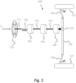
- Fig. 2 is a schematic figure of an alternative embodiment of a steering system 100'.
- the linkage consists of a steering rack 124 with associated tie rods 125 connected via a pinion 122 to an hydraulic assistance actuator 145 consisting of a hydraulically assisted steering rack (or similar in the case of Pitman arm based steering systems or Orbitrol valves in tractors or construction equipment).
- an angle overlay actuator 140 Between the hydraulic assistance actuator 145 and the feedback torque actuator 130, there is an angle overlay actuator 140.
- the angle overlay actuator 140 consists of a planetary gear or a harmonic drive, an overlay angle measurement sensor and an ECU.
- the steering column incorporates a torsion bar 128 with a torque sensor for measuring the steering torque above a feedback torque actuator 130, i.e. towards the steering wheel side.
- the feedback torque is actuated by the feedback torque actuator 130, which consists of an assistance motor and an ECU.
- the driver applies the driver torque, T D , in the steering wheel 120.
- T D driver torque
- Fig. 3 is a control diagram for the control of an angle overlay actuator control, path A, and a feedback torque actuator control, path B.
- a vehicle 390 with its several subsystems, has at every time a number of states, where a state is defined as a translational or rotational position, velocity or acceleration, or a force or torque. These states are schematically represented by a dashed line 305.
- the vehicle 390 is equipped with a series of sensors 310 for direct or indirect measurements of the vehicle states. Several sensors can be used such as a torsion-bar torque sensor, a steering-wheel angle sensor, vehicle wheel speed sensors, a vehicle yaw rate sensor, a vehicle lateral acceleration sensor or a cluster of vehicle velocities and rotational speeds.
- the sensed or measured values of the vehicle states 305 are communicated to the control steps by the use of a signal bus 315, where a signal bus is a transmission path on which signals can be read and/or transmitted.
- a signal bus is a transmission path on which signals can be read and/or transmitted.
- control paths there are two control paths (A and B) namely an angle overlay actuator control, path A, indicated by 310-320-330-340-345-350-360-390 and a feedback torque actuator control, path B, indicated by 310-320-370-380-390.
- the present invention provides a system and a method respectively for controlling a feedback torque actuator 130 and an angle overlay actuator 140 in a steering system 100, where these two actuators are so arranged that the feedback torque actuator 130 is closest to the steering wheel and the angle overlay actuator 140 is somewhere between the feedback torque actuator and the road wheels, and it is based on the fact that it incorporates a number of steps for a steering angle control and a number of steps for a feedback torque control.
- control of the angle overlay actuator incorporates the following steps:
- an additional overlay angle is received from a safety function 350 such as e.g. an oversteer compensation or understeer compensation function or any other safety function that might be used for achieving an additional overlay angle out of the scope of the present invention.
- the target overlay angle is then the sum 345 of the target overlay angle from the variable gear ratio and the additional overlay angle from said active safety function.
- the angle overlay actuator should be controlled, by the use of a controller, so that the deviation between the target overlay angle and the measured overlay angle is minimized.
- control of the feedback torque actuator incorporates the following steps:
- the target steering-wheel torque is achieved without any disturbances at the same time as the target overlay angle is achieved.
- the tyre friction torque takes into consideration the wheel angle, wheel angle history, vehicle position and vehicle velocity, which is important in the case of a low vehicle velocity since the tyre contact changes more quickly than the twisting of the tyre at high velocities.
- the steering system friction torque takes into consideration the fact that the steering system needs to have a certain friction for the driver to be able to rest against, so that the whole steering torque does not have to be given by the driver. A certain hysteresis is also needed so that the car is not felt to be "wobbly" or "unruly".
- the damping torque provides an important damping of the steering angle and thereby the vehicle response.
- the steering-wheel self-alignment torque means the steering-wheel goes back to the straight-forward position also at velocities so low that there is no yaw and/or lateral vehicle state feedback.
- the steering-wheel self-alignment torque can be an interpolation table or a software function.
- the target steering-wheel torque is a function of one or more of the following variables: vehicle speed, steering angle, steering angle velocity and/or steering angle acceleration.
- the parameters included in the target steering-wheel torque can be assessed in the event of a desired change in a vehicle state.
- HPAS hydraulic power assistance steering
- the feedback torque actuator is controlled to achieve a certain steering feel.
- steering feel is the relation between the feedback torque and the vehicle response. It is important to have this relation consistent in order to be confident with the steering, i.e. that the vehicle behaves equal for the same steering input and vice versa.
- the target for closed-loop control can be of two kinds, namely a target reference generator for a feedback torque calculated from a vehicle response or steering angle corresponding to a certain vehicle response (see further the description of the torque reference generator) or a target reference generator for a steering angle calculated from a steering-wheel torque (see further the description of the angle reference generator). Both methods result directly or indirectly in the fact that the feedback torque is controlled.
- this actuator is referred to as a feedback torque actuator.
- the placement of the angle overlay actuator, the feedback torque actuator and potentially also the hydraulic assistance torque actuator can be arbitrary as long as the torsion-bar torque sensor is placed above these two or three actuators. Then closed-loop feedback torque control is possible and steering feel can be controlled to achieve the positive benefits of this invention.
- the steering angle can be calculated in several ways, where they all have in common that they consist of an angle somewhere in the steering system that can be used to influence the lateral acceleration or curvature of the vehicle.
- Such steering angles can be:
- the driver torque is used as an input to a reference generator concept, an angle reference generator, so that the steering feel equation is used to achieve a target steering angle, which is possible to derive unambiguously as the target steering-wheel torque is a function of the, among others, the steering angle.
- the target overlay angle is then calculated by the use of the variable gear ratio and the additional overlay angle from the active safety functions such as e.g. oversteer compensation and/or understeer compensation and in the same way as in previous embodiments the feedback actuator and angle overlay actuator be controlled in order to achieve the target values respectively.
- the feedback torque actuator can be controlled using any form of reference generator concept, where here a torque reference generator concept and an angle reference generator concept is mentioned.
- the torque feedback actuator is above the angle overlay actuator, i.e. towards the steering wheel side, and in case of an additional hydraulic actuator, it can be mounted anywhere below the feedback torque actuator, i.e. towards the road wheel side, but preferably below the angle overlay actuator in order to reduce the torque to be handled by the angle overlay actuator.
Landscapes
- Engineering & Computer Science (AREA)
- Chemical & Material Sciences (AREA)
- Combustion & Propulsion (AREA)
- Transportation (AREA)
- Mechanical Engineering (AREA)
- Steering Control In Accordance With Driving Conditions (AREA)
Claims (15)
- Verfahren zum Steuern eines Fahrzeuglenkens in einem Fahrzeug mit einem Fahrzeuglenksystem (100); 100'), das einen Feedback-Drehmomentaktuator (130) aufweist, der in Reihe mit einem Winkelüberdeckungsaktuator (140) angeordnet ist, wobei das Verfahren aufweist: Steuern des Winkelüberdeckungsaktuators (140) in derartiger Weise, dass ein Sollüberdeckungswinkel erzielt wird, wobei der Feedback-Drehmomentaktuator (130) über dem Winkelüberdeckungsaktuator (140) angeordnet ist, das heißt zu der Lenkradseite hin,
dadurch gekennzeichnet, dass das Verfahren die folgenden Schritte aufweist:- Steuern des Winkelüberdeckungsaktuators (140) so, dass ein variables Lenkverhältnis und auch ein zusätzlicher, steuerbarer Überdeckungswinkel vorgesehen werden, und- Steuern des Feedback-Drehmomentaktuators (130) unter Verwendung eines Referenzgeneratorkonzepts für ein Lenkempfinden, das ein Steuerverfahren mit geschlossener Schleife ist, bei dem zuerst ein Referenzwert oder Sollwert berechnet wird und dann eine Lenkunterstützung gesteuert wird, um den Fehler zwischen dem Sollwert und einem entsprechenden gemessen Wert zu minimieren, indem der Referenzgenerator so gesteuert wird, dass ein Lenkempfindungssteuerfehler so minimiert wird, dass ein Solllenkempfinden, wobei eine Beziehung eines Feedback-Drehmomentes zu einem Fahrzeugansprechen das Lenkempfinden beschreibt, erzielt wird unter Verwendung des Referenzgenerator-Steuerverfahrens mit geschlossener Schleife, das Folgendes aufweist: Berechnen eines Referenz- oder Sollüberdeckungswinkelwertes; dann Steuern der Lenkunterstützung des Feedback-Drehmomentaktuators (130), um den Fehler zwischen dem Sollüberdeckungswinkelwert und einem entsprechenden gemessenen Überdeckungswinkel zu minimieren und in einer derartigen Weise, dass ein Solllenkempfinden erzielt wird, was dazu führt, dass die Winkelüberdeckung zur gleichen Zeit gesteuert wird, bei der das Lenkraddrehmoment gesteuert wird, wodurch ein Sollüberdeckungswinkel und ein gutes Lenkempfinden erzielt wird, wobei der Schritt zum Steuern des Feedback-Drehmomentaktuators (130) die folgenden Schritte aufweist:- Bestimmen eines Istlenkwinkels und einer Fahrzeuggeschwindigkeit unter Verwendung zumindest eines Eingabesignals, das mittels eines Sensors vorgesehen wird;- Verwenden des Istlenkwinkels und der Fahrzeuggeschwindigkeit zum Berechnen eines Solllenkwinkeldrehmoments;- Umwandeln des Solllenkwinkeldrehmomentes in eine Sollmotorstromstärke;- Vergleichen der Sollmotorstromstärke mit einer gemessenen Istmotorstromstärke;- Verwenden einer Steuereinrichtung zum Minimieren der Differenz zwischen der Sollmotorstromstärke und der gemessenen Istmotorstromstärke. - Verfahren gemäß Anspruch 1,
dadurch gekennzeichnet, dassder Referenzgenerator ein Feedback-Drehmomentreferenzgenerator ist zum Berechnen eines Sollfeedbackdrehmomentes, unddass das Unterstützungsdrehmoment so gesteuert wird, dass der Feedbackdrehmomentfehler minimiert wird. - Verfahren gemäß Anspruch 1,
dadurch gekennzeichnet, dassder Referenzgenerator ein Lenkwinkelreferenzgenerator ist zum Berechnen eines Solllenkwinkels, unddass das Unterstützungsmoment so gesteuert wird, dass ein Lenkwinkelfehler minimiert wird. - Verfahren gemäß einem der vorherigen Ansprüche,
dadurch gekennzeichnet, dass
die Schritte zum Steuern des Winkelüberdeckungsaktuators (140) die folgenden Schritte aufweisen:- Bestimmen zumindest entweder eines Istlenkwinkels, einer Fahrzeuggeschwindigkeit und/oder eines Überdeckungswinkels durch Messen zumindest eines Eingabesignals mittels zumindest einen Sensors. - Verfahren gemäß Anspruch 4,
dadurch gekennzeichnet, dass- die Messung des zumindest eines Eingabesignals Folgendes aufweist: Verwenden eines Radgeschwindigkeitssensors oder eines Antriebsachsengeschwindigkeitssensors, unddass das Verfahren des Weiteren den folgenden Schritt aufweist:- Berechnen der Fahrzeuggeschwindigkeit unter Verwendung des zumindest einen Eingabesignals. - Verfahren gemäß Anspruch 4 oder 5,
dadurch gekennzeichnet, dass
es die folgenden Schritte aufweist:- Bestimmen des Lenkwinkels, mit einer beliebigen Winkel- oder Stangenposition in dem Lenksystem, aus einem zusätzlichen Eingabesignal von dem zumindest einem Sensor, der einen Winkel- oder Positionssensor umfasst, der an der Lenksäule oder an einem anderen Ort im Lenksystem angeordnet ist, wobei der Lenkwinkel beispielsweise ein erfasster Winkel mal ein Verhältnis zwischen einer Rotation oder Translation eines Sensorelementes des Sensors und der Rotation bei dem Referenzlenkwinkel ist;- Bestimmen des Winkelüberdeckungsaktuatorwinkels direkt über ein Eingabesignal oder indirekt über eine Berechnung auf der Basis von zwei Lenkwinkeln, einer über und einer unter dem Winkelüberdeckungsaktuator;- Berechnen eines variablen Übersetzungsverhältnisses, das ein Sollverhältnis zwischen dem Lenkrad und dem Straßenrad umfasst;- Verwenden des variablen Übersetzungsverhältnisses zum Berechnen eines Sollüberdeckungswinkels, folglich Vorsehen eines Sollübersetzungsverhältnisses aus dem Sollüberdeckungswinkel und dem gegenwärtigen Lenkradwinkel;- Mittels einer Steuereinrichtung erfolgendes Steuern des Überdeckungswinkels zum Minimieren der Abweichung zwischen dem Sollüberdeckungswinkel und dem gemessenen oder berechneten Istüberdeckungswinkel. - Verfahren gemäß einem der vorherigen Ansprüche,
dadurch gekennzeichnet, dasses zwei Aktuatoren aufweist, den Feedback-Drehmomentaktuator (130) und den Winkelüberdeckungsaktuator (140), unddass lediglich der Feedback-Drehmomentaktuator (130) per geschlossener Schleife gesteuert wird, unddass der Feedback-Drehmomentaktuator (130) sämtliche Lenkunterstützungsaktuatorfunktionalität vorsieht. - Fahrzeuglenksystem (100; 100') mit einer Verbindung zwischen Vorderachsenstraßenrädern (127) und einem Winkelüberdeckungsaktuator (140), wobei die Verbindung Folgendes ausweist: eine Lenkstange (124) mit zugehörigen Spurstangen (125), die über ein Antriebszahnrad (122) mit dem Winkelüberdeckungsaktuator (140) verbunden sind, eine Säulenachse (135), einen Feedback-Drehmomentaktuator (130), der einen Unterstützungsmotor und eine ECU aufweist zum Erteilen eines Feedbacks zu einem Fahrer, ein Lenkrad (120), zu dem ein vom Fahrer aufgebrachtes Fahrerdrehmoment, TD , aufgebracht wird, und einen Torsionsstab (128) mit einem Torsionsstabdrehmomentsensor, wobei der Feedback-Drehmomentaktuator (130) über dem Winkelüberdeckungsaktuator (140) angeordnet ist, das heißt zu der Lenkradseite hin,
dadurch gekennzeichnet, dasses eine Einrichtung ausweist zum Steuern des Lenküberdeckungsaktuators (140) in derartiger Weise, dass ein variables Lenkverhältnis und auch ein zusätzlicher, steuerbarer Überdeckungswinkel vorgesehen werden,und zum Steuern des Feedback-Drehmomentaktuators (130) durch die Anwendung eines Referenzgeneratorkonzeptes für ein Lenkempfinden, das ein Steuerverfahren mit geschlossener Schleife ist, bei dem zuerst ein Referenz- oder Sollwert berechnet wird und dann eine Lenkunterstützung so gesteuert wird, dass der Fehler zwischen dem Sollwert und einem entsprechenden gemessenen Wert minimiert wird durch Steuern des Referenzgenerators, um einen Lenkempfindungssteuerfehler so zu minimieren, dass ein Sollfeedbackdrehmoment, wobei eine Beziehung eines Feedbackdrehmomentes zu einem Fahrzeugansprechen das Lenkempfinden beschreibt, erzielt wird, mit Berechnen eines Referenz- oder Sollüberdeckungswinkelwertes; dann erfolgendem Steuern der Lenkunterstützung des Feedback-Drehmomentaktuators (130), um den Fehler zwischen dem Sollüberdeckungswinkelwert und einem entsprechenden gemessenen Überdeckungswinkel zu minimieren, und in derartiger Weise, dass ein Solllenkempfinden erzielt wird, unddass zum Steuern des Feedback-Drehmomentaktuators (130) ein Sensor/Sensoren verwendet wird/werden zum Vorsehen zumindest eines Eingabesignals zum Bestimmen eines Istlenkwinkels und einer Fahrzeuggeschwindigkeit, wobei der vorbestimmte Istlenkwinkel und die vorbestimmte Fahrzeuggeschwindigkeit verwendet werden zum Berechnen eines Solllenkwinkeldrehmoments, dass es eine Einrichtung aufweist zum Umwandeln des Solllenkwinkel-Drehmomentes in eine Sollmotorstromstärke, und zum Vergleichen der Sollmotorstromstärke mit einer gemessenen Istmotorstromstärke, und mittels einer Steuereinrichtung erfolgenden Minimieren der Differenz zwischen der Sollmotorstromstärke und der gemessenen Istmotorstromstärke,sodass das Drehmoment in derartiger Weise gesteuert wird, dass ein Solllenkempfinden erzielt wird, was dazu führt, dass die Winkelüberdeckung zur gleichen Zeit gesteuert wird, bei der das Lenkwinkeldrehmoment gesteuert wird, wodurch ein Sollüberdeckungswinkel und ein günstiges Lenkempfinden erzielt wird. - Fahrzeuglenksystem gemäß Anspruch 8,
dadurch gekennzeichnet, dass
zum Steuern des Winkelüberdeckungsaktuators (140) es zumindest einen Sensor zum Messen von zumindest einem Eingabesignal aufweist zum Bestimmen von zumindest entweder einem Istlenkwinkel, einer Fahrzeuggeschwindigkeit und/oder einem Überdeckungswinkel. - Fahrzeuglenksystem gemäß Anspruch 9,
dadurch gekennzeichnet, dass
das zumindest eine Eingabesignal gemessen wird durch die Anwendung eines Radgeschwindigkeitssensors oder eines Antriebsachsengeschwindigkeitssensors, und dass das zumindest eine Eingabesignal verwendet wird für ein Berechnen der Fahrzeuggeschwindigkeit. - Fahrzeuglenksystem gemäß Anspruch 9 oder 10,
dadurch gekennzeichnet, dasses einen Winkelsensor aufweist, der an der Lenksäule oder an einem anderen Ort in dem Lenksystem angeordnet ist, unddass ein zusätzliches Eingabesignal von dem Winkelsensor verwendet wird zum Bestimmen des Lenkwinkels. - Fahrzeuglenksystem gemäß einem der Ansprüche 8 bis 11,
dadurch gekennzeichnet, dass
der Winkelüberdeckungsaktuatorwinkel direkt über ein Eingabesignal oder indirekt über eine Berechnung auf der Basis von zwei Lenkwinkeln bestimmt wird, einer über und einer unter dem Winkelüberdeckungsaktuator. - Fahrzeuglenksystem gemäß einem der Ansprüche 8 bis 12,
dadurch gekennzeichnet, dasses eine Einrichtung aufweist zum Berechnen eines variablen Übersetzungsverhältnisses, das ein Sollverhältnis zwischen dem Lenkrad und dem Straßenrad umfasst, wobei das variable Übersetzungsverhältnis für eine Berechnung eines Sollüberdeckungswinkels verwendet wird, folglich zum Vorsehen eines Sollübersetzungsverhältnisses aus dem Sollüberdeckungswinkel und dem gegenwärtigen Lenkradwinkel, unddass es des Weiteren eine Steuereinrichtung aufweist zum Steuern des Überdeckungswinkels, um die Abweichung zwischen dem Sollüberdeckungswinkel und dem gemessenen oder berechneten Istüberdeckungswinkel zu minimieren. - Fahrzeuglenksystem gemäß einem der Ansprüche 8 bis 13,
dadurch gekennzeichnet, dasses zwei Aktuatoren aufweist, den Feedback-Drehmomentaktuator (130) und den Winkelüberdeckungsaktuator (140),dass lediglich der Feedback-Drehmomentaktuator (130) per geschlossener Schleife gesteuert wird, unddass der Feedback-Drehmomentaktuator (130) sämtliche Lenkunterstützungsaktuatorfunktionalität vorsieht. - Fahrzeuglenksystem gemäß einem der Ansprüche 8 bis 13,
dadurch gekennzeichnet, dass
es des Weiteren einen hydraulischen Unterstützungsaktuator (145) aufweist, mit dem die Spurstangen über das Antriebszahnrad (122) so verbunden sind, dass der Winkelüberdeckungsaktuator (140) zwischen dem hydraulischen Unterstützungsaktuator (145) und dem Feedback-Drehmomentaktuator (130) angeordnet ist, wobei der hydraulische Unterstützungsaktuator (145) beispielsweise eine hydraulisch unterstützte Lenkstange aufweist.
Applications Claiming Priority (2)
| Application Number | Priority Date | Filing Date | Title |
|---|---|---|---|
| SE1850315A SE1850315A1 (en) | 2018-03-20 | 2018-03-20 | Method and system for controlling vehicle steering |
| PCT/SE2019/050237 WO2019182496A1 (en) | 2018-03-20 | 2019-03-16 | Method and system for controlling vehicle steering |
Publications (2)
| Publication Number | Publication Date |
|---|---|
| EP3768575A1 EP3768575A1 (de) | 2021-01-27 |
| EP3768575B1 true EP3768575B1 (de) | 2024-12-04 |
Family
ID=65952042
Family Applications (1)
| Application Number | Title | Priority Date | Filing Date |
|---|---|---|---|
| EP19713890.2A Active EP3768575B1 (de) | 2018-03-20 | 2019-03-16 | Verfahren und system zur steuerung einer fahrzeuglenkung |
Country Status (5)
| Country | Link |
|---|---|
| US (1) | US11873042B2 (de) |
| EP (1) | EP3768575B1 (de) |
| CN (1) | CN112074449B (de) |
| SE (1) | SE1850315A1 (de) |
| WO (1) | WO2019182496A1 (de) |
Families Citing this family (21)
| Publication number | Priority date | Publication date | Assignee | Title |
|---|---|---|---|---|
| US11414122B2 (en) * | 2019-03-01 | 2022-08-16 | Steering Solutions Ip Holding Corporation | Handwheel-roadwheel resynchronization in steer-by-wire systems |
| KR102173996B1 (ko) * | 2019-05-16 | 2020-11-04 | 주식회사 만도 | 조향 제어 장치와 그 방법, 및 조향 제어 시스템 |
| SE544124C2 (en) | 2019-10-13 | 2022-01-04 | Sentient Ab | A method and a system arrangement for vehicle steering and a vehicle with such a system |
| EP3875350B1 (de) * | 2020-03-06 | 2024-08-07 | Zenuity AB | Verfahren und anordnung zur sicherstellung der strassenverfolgung bis zu einer vordefinierten querbeschleunigungsgrenze unter verwendung eines pid-reglers in einem fahrzeug |
| EP3882106B1 (de) * | 2020-03-17 | 2022-06-01 | Volvo Car Corporation | Verfahren und vorrichtung zum betrieb eines fahrzeuglenksystems |
| GB2602478B (en) * | 2020-12-31 | 2024-12-11 | Zf Automotive Uk Ltd | Motor control in an electric power steering |
| US11052940B1 (en) | 2021-03-12 | 2021-07-06 | Canoo Technologies Inc. | Steer-by-wire systems and methods of operating thereof in vehicles |
| DE102021202482B4 (de) * | 2021-03-15 | 2023-06-29 | Continental Automotive Technologies GmbH | Regelungseinrichtung und Verfahren zur Lenkwinkelregelung eines Fahrzeugs |
| DE102021204996A1 (de) * | 2021-05-18 | 2022-11-24 | Zf Automotive Germany Gmbh | Verfahren zur Bestimmung eines Lenkdämpfungsbedarfs, Lenksystem, Computerprogrammprodukt und Speichermedium |
| CN113212543B (zh) * | 2021-06-11 | 2022-04-08 | 南京航空航天大学 | 一种变传动比循环球式电液转向系统及其控制方法 |
| CN117651674A (zh) * | 2021-07-14 | 2024-03-05 | 本田技研工业株式会社 | 用于车辆的转向系统 |
| CN113665664B (zh) * | 2021-08-06 | 2022-08-19 | 上海汽车工业(集团)总公司 | Sbw角度跟随前馈控制方法、存储介质和控制系统 |
| CN113443003B (zh) * | 2021-08-19 | 2022-06-03 | 浙江吉利控股集团有限公司 | 转向助力电机的控制方法及设备 |
| GB202201948D0 (en) * | 2022-02-15 | 2022-03-30 | Agco Int Gmbh | An electro-hydraulic steering system and a method of controlling an electro hydraulic steering system |
| CN114852168B (zh) * | 2022-04-26 | 2023-11-03 | 吉林大学 | 一种基于驾驶员转向意图的操纵摇杆变角传动比控制方法 |
| US12246785B2 (en) | 2022-09-14 | 2025-03-11 | Toyota Research Institute, Inc. | Automated steering system during loss of traction |
| CN115571132B (zh) * | 2022-10-10 | 2026-03-27 | 嬴彻星创智能科技(上海)有限公司 | 一种自动转向控制方法及装置 |
| CN116198595B (zh) * | 2023-02-27 | 2026-03-20 | 浙江极氪智能科技有限公司 | 一种方向盘的参数调整方法、装置、介质和设备 |
| AT526930B1 (de) | 2023-05-11 | 2024-09-15 | Avl List Gmbh | Lenkeinrichtung |
| DE102023210367A1 (de) * | 2023-10-20 | 2025-04-24 | Zf Automotive Germany Gmbh | Steer-by-wire-Lenksystem und Verfahren |
| CN119975533B (zh) * | 2025-03-19 | 2025-12-02 | 杭州智元研究院有限公司 | 一种多轴车辆分布式转向系统及其控制方法 |
Family Cites Families (18)
| Publication number | Priority date | Publication date | Assignee | Title |
|---|---|---|---|---|
| JP3696466B2 (ja) * | 2000-01-31 | 2005-09-21 | 光洋精工株式会社 | 車両用操舵装置 |
| US7392122B2 (en) * | 2002-06-13 | 2008-06-24 | Oshkosh Truck Corporation | Steering control system and method |
| US7240760B2 (en) * | 2005-07-25 | 2007-07-10 | Trw Automotive U.S. Llc | Steering apparatus |
| JP4254777B2 (ja) * | 2005-11-11 | 2009-04-15 | トヨタ自動車株式会社 | 車輌用操舵制御装置 |
| JP2008087672A (ja) | 2006-10-03 | 2008-04-17 | Jtekt Corp | 車両用操舵装置 |
| US7832523B2 (en) * | 2007-03-29 | 2010-11-16 | Ford Global Technologies | Power assist steering system |
| US8116943B2 (en) * | 2008-04-24 | 2012-02-14 | GM Global Technology Operations LLC | Method and apparatus for minimizing driver disturbance in a limited by-wire active steering system |
| US20100072738A1 (en) * | 2008-09-19 | 2010-03-25 | Trw Automotive U.S. Llc | Steering System |
| DE102011003716A1 (de) | 2011-02-07 | 2012-08-09 | Bayerische Motoren Werke Aktiengesellschaft | Überlagerungslenksystem eines Kraftfahrzeugs |
| DE202011003716U1 (de) | 2011-03-09 | 2011-09-08 | Gerhard M. Beier | CNT-Doppelrohr Behälterheizanlage |
| EP2987701B1 (de) * | 2014-08-22 | 2017-10-11 | Ford Global Technologies, LLC | Präzise Steuerung mit geschlossenem Regelkreises einer Laufradeinschlagwinkelrücksetzung Lenkradwinkel durch eine elektrische Servolenkung |
| US20170017734A1 (en) * | 2015-07-15 | 2017-01-19 | Ford Global Technologies, Llc | Crowdsourced Event Reporting and Reconstruction |
| US9845108B2 (en) * | 2015-10-23 | 2017-12-19 | Ford Global Technologies, Llc | Systems and methods for estimating steering assistance |
| KR102341111B1 (ko) * | 2015-12-14 | 2021-12-21 | 현대모비스 주식회사 | 전동식 조향 장치 및 그 제어 방법 |
| CN108602529B (zh) * | 2016-02-05 | 2021-11-30 | 感知知识产权有限公司 | 用于控制车辆转向和车辆行为的方法 |
| US10214238B2 (en) * | 2016-11-09 | 2019-02-26 | Ford Global Technologies, Llc | Voltage compensating anti-catch algorithm for active front steering system |
| US10315691B2 (en) * | 2017-03-30 | 2019-06-11 | Ford Global Technologies, Llc | Methods and apparatus to correct clear vision errors in a vehicle steering system |
| US10232873B2 (en) * | 2017-03-30 | 2019-03-19 | Ford Global Technologies, Llc | Methods and apparatus to identify non-uniformity in a vehicle steering system |
-
2018
- 2018-03-20 SE SE1850315A patent/SE1850315A1/en not_active Application Discontinuation
-
2019
- 2019-03-16 WO PCT/SE2019/050237 patent/WO2019182496A1/en not_active Ceased
- 2019-03-16 EP EP19713890.2A patent/EP3768575B1/de active Active
- 2019-03-16 US US16/977,256 patent/US11873042B2/en active Active
- 2019-03-16 CN CN201980020378.9A patent/CN112074449B/zh active Active
Also Published As
| Publication number | Publication date |
|---|---|
| CN112074449A (zh) | 2020-12-11 |
| EP3768575A1 (de) | 2021-01-27 |
| US11873042B2 (en) | 2024-01-16 |
| US20200406964A1 (en) | 2020-12-31 |
| WO2019182496A1 (en) | 2019-09-26 |
| SE1850315A1 (en) | 2019-09-21 |
| CN112074449B (zh) | 2024-03-01 |
Similar Documents
| Publication | Publication Date | Title |
|---|---|---|
| US11873042B2 (en) | Method and system for controlling vehicle steering | |
| US12344340B2 (en) | Method and system arrangement for vehicle steering and vehicle with such a system | |
| EP3684675B1 (de) | Verfahren und system zum halten einer fahrzeugfahrspur | |
| EP3411280B1 (de) | Verfahren zur steuerung eines fahrzeugs und fahrzeugverhalten | |
| EP3445638B1 (de) | Verfahren zur steuerung einer fahrzeuglenkung | |
| EP4479287B1 (de) | Lenksystem, verfahren zur bereitstellung von lenkrückmeldung in einem derartigen system und lenksystemrückkopplungsanordnung | |
| EP3847077B1 (de) | Verfahren und system zur kombinierten hydraulischen und elektrischen servolenkung | |
| JP3905142B2 (ja) | 無軌道車両の走行特性安定化システム、パワーステアリングシステムおよび油圧操舵装置 |
Legal Events
| Date | Code | Title | Description |
|---|---|---|---|
| STAA | Information on the status of an ep patent application or granted ep patent |
Free format text: STATUS: UNKNOWN |
|
| STAA | Information on the status of an ep patent application or granted ep patent |
Free format text: STATUS: THE INTERNATIONAL PUBLICATION HAS BEEN MADE |
|
| PUAI | Public reference made under article 153(3) epc to a published international application that has entered the european phase |
Free format text: ORIGINAL CODE: 0009012 |
|
| STAA | Information on the status of an ep patent application or granted ep patent |
Free format text: STATUS: REQUEST FOR EXAMINATION WAS MADE |
|
| 17P | Request for examination filed |
Effective date: 20200917 |
|
| AK | Designated contracting states |
Kind code of ref document: A1 Designated state(s): AL AT BE BG CH CY CZ DE DK EE ES FI FR GB GR HR HU IE IS IT LI LT LU LV MC MK MT NL NO PL PT RO RS SE SI SK SM TR |
|
| AX | Request for extension of the european patent |
Extension state: BA ME |
|
| RAP3 | Party data changed (applicant data changed or rights of an application transferred) |
Owner name: SENTIENT IP AB |
|
| DAV | Request for validation of the european patent (deleted) | ||
| DAX | Request for extension of the european patent (deleted) | ||
| STAA | Information on the status of an ep patent application or granted ep patent |
Free format text: STATUS: EXAMINATION IS IN PROGRESS |
|
| 17Q | First examination report despatched |
Effective date: 20211130 |
|
| GRAP | Despatch of communication of intention to grant a patent |
Free format text: ORIGINAL CODE: EPIDOSNIGR1 |
|
| STAA | Information on the status of an ep patent application or granted ep patent |
Free format text: STATUS: GRANT OF PATENT IS INTENDED |
|
| GRAS | Grant fee paid |
Free format text: ORIGINAL CODE: EPIDOSNIGR3 |
|
| INTG | Intention to grant announced |
Effective date: 20240926 |
|
| GRAA | (expected) grant |
Free format text: ORIGINAL CODE: 0009210 |
|
| STAA | Information on the status of an ep patent application or granted ep patent |
Free format text: STATUS: THE PATENT HAS BEEN GRANTED |
|
| AK | Designated contracting states |
Kind code of ref document: B1 Designated state(s): AL AT BE BG CH CY CZ DE DK EE ES FI FR GB GR HR HU IE IS IT LI LT LU LV MC MK MT NL NO PL PT RO RS SE SI SK SM TR |
|
| REG | Reference to a national code |
Ref country code: GB Ref legal event code: FG4D |
|
| REG | Reference to a national code |
Ref country code: CH Ref legal event code: EP |
|
| REG | Reference to a national code |
Ref country code: DE Ref legal event code: R096 Ref document number: 602019062917 Country of ref document: DE |
|
| REG | Reference to a national code |
Ref country code: IE Ref legal event code: FG4D |
|
| REG | Reference to a national code |
Ref country code: LT Ref legal event code: MG9D |
|
| REG | Reference to a national code |
Ref country code: NL Ref legal event code: MP Effective date: 20241204 |
|
| PG25 | Lapsed in a contracting state [announced via postgrant information from national office to epo] |
Ref country code: HR Free format text: LAPSE BECAUSE OF FAILURE TO SUBMIT A TRANSLATION OF THE DESCRIPTION OR TO PAY THE FEE WITHIN THE PRESCRIBED TIME-LIMIT Effective date: 20241204 |
|
| PG25 | Lapsed in a contracting state [announced via postgrant information from national office to epo] |
Ref country code: FI Free format text: LAPSE BECAUSE OF FAILURE TO SUBMIT A TRANSLATION OF THE DESCRIPTION OR TO PAY THE FEE WITHIN THE PRESCRIBED TIME-LIMIT Effective date: 20241204 |
|
| PG25 | Lapsed in a contracting state [announced via postgrant information from national office to epo] |
Ref country code: BG Free format text: LAPSE BECAUSE OF FAILURE TO SUBMIT A TRANSLATION OF THE DESCRIPTION OR TO PAY THE FEE WITHIN THE PRESCRIBED TIME-LIMIT Effective date: 20241204 |
|
| PG25 | Lapsed in a contracting state [announced via postgrant information from national office to epo] |
Ref country code: ES Free format text: LAPSE BECAUSE OF FAILURE TO SUBMIT A TRANSLATION OF THE DESCRIPTION OR TO PAY THE FEE WITHIN THE PRESCRIBED TIME-LIMIT Effective date: 20241204 |
|
| PG25 | Lapsed in a contracting state [announced via postgrant information from national office to epo] |
Ref country code: NO Free format text: LAPSE BECAUSE OF FAILURE TO SUBMIT A TRANSLATION OF THE DESCRIPTION OR TO PAY THE FEE WITHIN THE PRESCRIBED TIME-LIMIT Effective date: 20250304 |
|
| PG25 | Lapsed in a contracting state [announced via postgrant information from national office to epo] |
Ref country code: GR Free format text: LAPSE BECAUSE OF FAILURE TO SUBMIT A TRANSLATION OF THE DESCRIPTION OR TO PAY THE FEE WITHIN THE PRESCRIBED TIME-LIMIT Effective date: 20250305 Ref country code: LV Free format text: LAPSE BECAUSE OF FAILURE TO SUBMIT A TRANSLATION OF THE DESCRIPTION OR TO PAY THE FEE WITHIN THE PRESCRIBED TIME-LIMIT Effective date: 20241204 |
|
| PG25 | Lapsed in a contracting state [announced via postgrant information from national office to epo] |
Ref country code: RS Free format text: LAPSE BECAUSE OF FAILURE TO SUBMIT A TRANSLATION OF THE DESCRIPTION OR TO PAY THE FEE WITHIN THE PRESCRIBED TIME-LIMIT Effective date: 20250304 |
|
| PG25 | Lapsed in a contracting state [announced via postgrant information from national office to epo] |
Ref country code: NL Free format text: LAPSE BECAUSE OF FAILURE TO SUBMIT A TRANSLATION OF THE DESCRIPTION OR TO PAY THE FEE WITHIN THE PRESCRIBED TIME-LIMIT Effective date: 20241204 |
|
| REG | Reference to a national code |
Ref country code: AT Ref legal event code: MK05 Ref document number: 1747902 Country of ref document: AT Kind code of ref document: T Effective date: 20241204 |
|
| PG25 | Lapsed in a contracting state [announced via postgrant information from national office to epo] |
Ref country code: SM Free format text: LAPSE BECAUSE OF FAILURE TO SUBMIT A TRANSLATION OF THE DESCRIPTION OR TO PAY THE FEE WITHIN THE PRESCRIBED TIME-LIMIT Effective date: 20241204 |
|
| PG25 | Lapsed in a contracting state [announced via postgrant information from national office to epo] |
Ref country code: PL Free format text: LAPSE BECAUSE OF FAILURE TO SUBMIT A TRANSLATION OF THE DESCRIPTION OR TO PAY THE FEE WITHIN THE PRESCRIBED TIME-LIMIT Effective date: 20241204 |
|
| PG25 | Lapsed in a contracting state [announced via postgrant information from national office to epo] |
Ref country code: IS Free format text: LAPSE BECAUSE OF FAILURE TO SUBMIT A TRANSLATION OF THE DESCRIPTION OR TO PAY THE FEE WITHIN THE PRESCRIBED TIME-LIMIT Effective date: 20250404 |
|
| PG25 | Lapsed in a contracting state [announced via postgrant information from national office to epo] |
Ref country code: PT Free format text: LAPSE BECAUSE OF FAILURE TO SUBMIT A TRANSLATION OF THE DESCRIPTION OR TO PAY THE FEE WITHIN THE PRESCRIBED TIME-LIMIT Effective date: 20250404 |
|
| PG25 | Lapsed in a contracting state [announced via postgrant information from national office to epo] |
Ref country code: EE Free format text: LAPSE BECAUSE OF FAILURE TO SUBMIT A TRANSLATION OF THE DESCRIPTION OR TO PAY THE FEE WITHIN THE PRESCRIBED TIME-LIMIT Effective date: 20241204 |
|
| PG25 | Lapsed in a contracting state [announced via postgrant information from national office to epo] |
Ref country code: AT Free format text: LAPSE BECAUSE OF FAILURE TO SUBMIT A TRANSLATION OF THE DESCRIPTION OR TO PAY THE FEE WITHIN THE PRESCRIBED TIME-LIMIT Effective date: 20241204 Ref country code: RO Free format text: LAPSE BECAUSE OF FAILURE TO SUBMIT A TRANSLATION OF THE DESCRIPTION OR TO PAY THE FEE WITHIN THE PRESCRIBED TIME-LIMIT Effective date: 20241204 |
|
| PG25 | Lapsed in a contracting state [announced via postgrant information from national office to epo] |
Ref country code: SK Free format text: LAPSE BECAUSE OF FAILURE TO SUBMIT A TRANSLATION OF THE DESCRIPTION OR TO PAY THE FEE WITHIN THE PRESCRIBED TIME-LIMIT Effective date: 20241204 |
|
| PG25 | Lapsed in a contracting state [announced via postgrant information from national office to epo] |
Ref country code: CZ Free format text: LAPSE BECAUSE OF FAILURE TO SUBMIT A TRANSLATION OF THE DESCRIPTION OR TO PAY THE FEE WITHIN THE PRESCRIBED TIME-LIMIT Effective date: 20241204 |
|
| REG | Reference to a national code |
Ref country code: DE Ref legal event code: R097 Ref document number: 602019062917 Country of ref document: DE |
|
| PG25 | Lapsed in a contracting state [announced via postgrant information from national office to epo] |
Ref country code: SE Free format text: LAPSE BECAUSE OF FAILURE TO SUBMIT A TRANSLATION OF THE DESCRIPTION OR TO PAY THE FEE WITHIN THE PRESCRIBED TIME-LIMIT Effective date: 20241204 |
|
| PG25 | Lapsed in a contracting state [announced via postgrant information from national office to epo] |
Ref country code: DK Free format text: LAPSE BECAUSE OF FAILURE TO SUBMIT A TRANSLATION OF THE DESCRIPTION OR TO PAY THE FEE WITHIN THE PRESCRIBED TIME-LIMIT Effective date: 20241204 |
|
| PLBE | No opposition filed within time limit |
Free format text: ORIGINAL CODE: 0009261 |
|
| STAA | Information on the status of an ep patent application or granted ep patent |
Free format text: STATUS: NO OPPOSITION FILED WITHIN TIME LIMIT |
|
| PG25 | Lapsed in a contracting state [announced via postgrant information from national office to epo] |
Ref country code: MC Free format text: LAPSE BECAUSE OF FAILURE TO SUBMIT A TRANSLATION OF THE DESCRIPTION OR TO PAY THE FEE WITHIN THE PRESCRIBED TIME-LIMIT Effective date: 20241204 |
|
| REG | Reference to a national code |
Ref country code: CH Ref legal event code: L10 Free format text: ST27 STATUS EVENT CODE: U-0-0-L10-L00 (AS PROVIDED BY THE NATIONAL OFFICE) Effective date: 20251015 |
|
| REG | Reference to a national code |
Ref country code: CH Ref legal event code: H13 Free format text: ST27 STATUS EVENT CODE: U-0-0-H10-H13 (AS PROVIDED BY THE NATIONAL OFFICE) Effective date: 20251023 |
|
| 26N | No opposition filed |
Effective date: 20250905 |
|
| PG25 | Lapsed in a contracting state [announced via postgrant information from national office to epo] |
Ref country code: LU Free format text: LAPSE BECAUSE OF NON-PAYMENT OF DUE FEES Effective date: 20250316 |
|
| REG | Reference to a national code |
Ref country code: BE Ref legal event code: MM Effective date: 20250331 |
|
| PG25 | Lapsed in a contracting state [announced via postgrant information from national office to epo] |
Ref country code: BE Free format text: LAPSE BECAUSE OF NON-PAYMENT OF DUE FEES Effective date: 20250331 |
|
| PG25 | Lapsed in a contracting state [announced via postgrant information from national office to epo] |
Ref country code: CH Free format text: LAPSE BECAUSE OF NON-PAYMENT OF DUE FEES Effective date: 20250331 |
|
| PG25 | Lapsed in a contracting state [announced via postgrant information from national office to epo] |
Ref country code: IE Free format text: LAPSE BECAUSE OF NON-PAYMENT OF DUE FEES Effective date: 20250316 |
|
| PGFP | Annual fee paid to national office [announced via postgrant information from national office to epo] |
Ref country code: GB Payment date: 20260317 Year of fee payment: 8 |
|
| PGFP | Annual fee paid to national office [announced via postgrant information from national office to epo] |
Ref country code: DE Payment date: 20260318 Year of fee payment: 8 |
|
| PGFP | Annual fee paid to national office [announced via postgrant information from national office to epo] |
Ref country code: IT Payment date: 20260319 Year of fee payment: 8 |
|
| PGFP | Annual fee paid to national office [announced via postgrant information from national office to epo] |
Ref country code: FR Payment date: 20260317 Year of fee payment: 8 |