EP3768416B1 - Fluid-bed granulator system with coating material to prevent dust buildup in the air systems of urea granulation plants - Google Patents
Fluid-bed granulator system with coating material to prevent dust buildup in the air systems of urea granulation plants Download PDFInfo
- Publication number
- EP3768416B1 EP3768416B1 EP19711917.5A EP19711917A EP3768416B1 EP 3768416 B1 EP3768416 B1 EP 3768416B1 EP 19711917 A EP19711917 A EP 19711917A EP 3768416 B1 EP3768416 B1 EP 3768416B1
- Authority
- EP
- European Patent Office
- Prior art keywords
- fluid
- bed granulator
- duct
- connection
- urea
- Prior art date
- Legal status (The legal status is an assumption and is not a legal conclusion. Google has not performed a legal analysis and makes no representation as to the accuracy of the status listed.)
- Active
Links
Images

Classifications
-
- C—CHEMISTRY; METALLURGY
- C05—FERTILISERS; MANUFACTURE THEREOF
- C05C—NITROGENOUS FERTILISERS
- C05C9/00—Fertilisers containing urea or urea compounds
- C05C9/005—Post-treatment
-
- B—PERFORMING OPERATIONS; TRANSPORTING
- B01—PHYSICAL OR CHEMICAL PROCESSES OR APPARATUS IN GENERAL
- B01J—CHEMICAL OR PHYSICAL PROCESSES, e.g. CATALYSIS OR COLLOID CHEMISTRY; THEIR RELEVANT APPARATUS
- B01J2/00—Processes or devices for granulating materials, e.g. fertilisers in general; Rendering particulate materials free flowing in general, e.g. making them hydrophobic
- B01J2/16—Processes or devices for granulating materials, e.g. fertilisers in general; Rendering particulate materials free flowing in general, e.g. making them hydrophobic by suspending the powder material in a gas, e.g. in fluidised beds or as a falling curtain
-
- C—CHEMISTRY; METALLURGY
- C05—FERTILISERS; MANUFACTURE THEREOF
- C05G—MIXTURES OF FERTILISERS COVERED INDIVIDUALLY BY DIFFERENT SUBCLASSES OF CLASS C05; MIXTURES OF ONE OR MORE FERTILISERS WITH MATERIALS NOT HAVING A SPECIFIC FERTILISING ACTIVITY, e.g. PESTICIDES, SOIL-CONDITIONERS, WETTING AGENTS; FERTILISERS CHARACTERISED BY THEIR FORM
- C05G5/00—Fertilisers characterised by their form
- C05G5/10—Solid or semi-solid fertilisers, e.g. powders
- C05G5/12—Granules or flakes
Definitions
- the invention relates to a fluid-bed granulator with a coated vent duct, a plant comprising a fluid-bed granulator with a coated vent duct and the use of the fluid-bed granulator for the production of fertilizer granules.
- fertilizers may contain nitrogen, phosphate, sulfur, potassium or micronutrients.
- a common, widely used fertilizer contains urea as its main component.
- the water soluble urea rapidly decomposes in the soil, providing ammonia and nitrate compounds.
- the fertilizer may contain only urea or a combination of urea with one or more of the before mentioned components, e.g. phosphate, sulfur, potassium or micronutrients.
- Urea can be produced on a large industrial scale by reacting ammonia with carbon dioxide via a (simplified) two-step reaction:
- Solid urea particles as required for fertilizer applications, are produced in a finishing section e.g. by granulation, prilling or crystallization.
- the absorbance of water due to the hygroscopic nature of urea easily results in uncontrolled aggregation, quality degradation and caking of fine, untreated urea particles. This process can negatively affect the solubility, bulk storage, durability or chemical stability of the urea fertilizer.
- the uncontrolled gain in weight by absorbing water increases the transport weight and costs. Therefore, further post synthesis process steps are necessary in order to provide a transportable and storable urea fertilizer.
- Common technical processes include diverse solidification processes like prilling, drum granulation or fluid-bed granulation. Especially the prilling processes suffer from some critical drawbacks like relatively soft particles and sometimes deformed inhomogeneous particles.
- fluid-bed granulation process of urea can be found in WO 2010/060535 A1 , e.g. in paragraphs [0025]-[0035], figure 1 or in US 4,701,353 A , DE 31 16 778 A1 and US 4,219,589 A .
- Urea fertilizers can be combined with ammonium sulfate or elemental sulfur, therefore providing both plant nutrients nitrogen and sulfur in one fertilizer.
- Ammonia sulfur can be directly used by the plant, whereas elemental sulfur needs to be decomposed by soil microorganisms, thereby providing long-term plant nutrients. Examples of urea/sulfur granules can be found e.g. in US 4,330,319 A .
- the fluid-bed granulation process is based on providing granulation seeds, which grow by absorbing very small droplets of a growth liquid. These small droplets can be provided via an "atomized" liquid urea melt.
- atomized used in the description refers to a mixing process of the liquid urea melt (or other suitable fertilizer melts) with a pressurized medium like air. This mixing process creates a liquid/gas emulsion or an aerosol of small droplets.
- the term “atomized” should therefore not be confused with a molecular separating process of atomic/covalent bonds.
- the produced droplets may have a medium size distribution around 1 ⁇ m to 200 ⁇ m.
- the in-situ produced warm particles show a significant adhesion/wetting affinity.
- This adhesion may result in the before mentioned caking or even a (partiality) adsorption of urea granules on the granulator walls.
- This adsorption process of granules may even lead to a partial or total blocking of the fluid-bed granulator walls, vent openings and ducts. This blocking requires extensive cleaning measures or even complete shutdowns of the fluid-bed granulator.
- GB 1,395,906 A discloses a prilling unit with a non-wetting coating.
- the coating may be located at the nozzles and distributor plates.
- DD 118 287 discloses reactor wall coatings suitable for the polymerization of vinyl polymers.
- EP 2 832 439 A1 discloses a reactor for producing nitrogen-containing fertilizer granules, wherein the inside walls of said reactor are extensively coated with a layer of at least one organic silicon compound.
- Preferred embodiments of the invention are subject to the corresponding dependent claims.
- the fluid-bed granulator system comprises a fluid-bed granulator with an air vent opening. Dust, e.g. urea dust, and chemical vapors like ammonia, which are created or released during the granulation process, are removed in a scrubber unit.
- the scrubber unit comprises at least a dust removing scrubber and an ammonia removing scrubber. Examples of suitable scrubbers can be found in WO 2005/032696 A1 ( figure 1 ) or WO2010/60535 A1 .
- a connection-duct is located between the air vent opening of the fluid-bed granulator and the scrubber unit. This connection-duct transfers the before mentioned dust (e.g. urea dust), vapors and gases to the scrubber unit.
- connection-duct is at least partially coated with an anti-adhesion layer, preferably comprising an (or more) organic silicon compound(s) or fluorinated organic compounds, e.g. polytetrafluorethylene.
- an anti-adhesion layer preferably comprising an (or more) organic silicon compound(s) or fluorinated organic compounds, e.g. polytetrafluorethylene.
- the term "partially coating” relates to a coating covering at least 5 % respective 10 % of the inner connection surface, more preferably at least 30 %.
- the anti-adhesion layer decreases the adhesion affinity of the granulation dust within the connection-duct.
- connection-duct is coated starting from the air vent opening to the first connection-duct bending (preferably approximately 90 degree angle shape).
- the first connection-duct bending results in a change of the flow direction based on the bending angle.
- the bending angle is the range of between plus/minus 10 degree to 170 degree, more preferably in the range from plus
- the fluid-bed granulator comprises at least a granulator space inside the fluid-bed granulator.
- the fluid-bed granulator further comprises a perforated plate located inside the granulator space and spray nozzles located in, on, above or beside the perforated plate.
- the spray nozzles are attached to the perforated plate.
- a fluidization air inlet preferably located below the perforated plate, provides the necessary fluidization air for the fluid bed of fertilizer granules.
- the term "fluidization air” includes air or inert gases like carbon dioxide (CO 2 ), nitrogen, argon or mixtures thereof.
- the spray nozzles are connected with supply lines for atomization air and supply lines for a liquid melt, preferably a liquid melt containing urea.
- these supply lines for air and melt can be combined in one line.
- the fluid-bed granulator comprises a granulation seeds inlet.
- a granulation seeds inlet comprises internal and external devices, lines and openings for the introduction of granular seeds.
- internal refers to the production of granular seeds within the granulator.
- exital refers to the provision or production of granular seeds from outside the granulator, e.g. via sieves or crushers outside the fluid-bed granulator.
- the fluid-bed granulator comprises a granulator outlet opening and the air vent opening.
- the position of the air-vent opening is not fixed within the fluid-bed granulator.
- the air-vent opening is placed next to and/or above the granulation seeds inlet.
- the granulator space comprises separating walls, optionally with integrated openings. These separating walls may further alter and modify the speed of the fluid bed towards the granulator outlet opening.
- the anti-adhesion layer comprises an organic silicon compound.
- These silicon compounds effectively reduce the dust adhesion in the connection-duct and prevent/reduce the build-up of obstructing solid matter in the connection-duct. Examples of suitable coating procedures with organic silicon compounds, e.g. based on methylpolysiloxane, can be found in EP 2 832 439 A1 , paragraphs [0018]-[0025] and [0030].
- At least 10 %, preferably at least 30 %, more preferably at least 50 %, of the inner surface of the connection-duct is coated with the anti-adhesion layer.
- a cleaning nozzle preferably 1 to 6 cleaning nozzles, is/are located inside the connection-duct.
- the cleaning nozzle comprises nozzles types suitable for spraying water, providing additional cleaning means in the connection-duct.
- more than one cleaning nozzle is located inside the connection-duct.
- the cleaning nozzles are arranged alongside the air flow direction and/or orthogonal to the air flow.
- the cleaning nozzles enable a suitable cooling of the dust and gas streams inside the connection-duct, thereby reducing the temperature of the gas/dust in the connection-duct and the scrubber unit.
- the cleaning nozzle is located at a place/space within 2 % to 90 %, preferably between 5 % to 50 %, of the in-duct distance between the air vent opening and the scrubber unit inside the connection-duct.
- in-duct distance refers to the distance within the connection-duct measured from the air vent opening to the scrubber unit.
- the relative value "0 %” refers directly to the air vent opening.
- the relative value "100 %” refers to the complete (before mentioned) in-duct distance, ending at the scrubber unit inlet.
- d 0 defines a starting point at the vent opening and d 100 defines an end point at scrubber opening. Therefore, a relative in-duct position, e.g. of the cleaning nozzles, within the inner space of the connection-duct is preferably indicated as d i .
- the inventive coating enables a far more remote placement, indicated as d i and referring to the vent opening of the cleaning nozzle in the connection-duct.
- This remote placement within a space of between 2 % (d 2 ) to 90 % (d 90 ) in-duct distance prohibits a reflux of cleaning liquids from a cleaning nozzle to the fluid granulator, more preferably in a vertical section of the connection-duct, thereby effectively preventing any reflux into the granulator space.
- reflux of cleaning liquids into the fluid-bed granulator would otherwise occur if the cleaning nozzles would be placed near the vent-opening of the connection-duct.
- a non-coated connection-duct requires cleaning means, e.g.
- a cleaning nozzle located near the vent opening, outside the before mentioned space of between 2 % (d 10 ) to 90 % (d 90 ) of the in-duct distance, in order to remove a urea dust adhesion and avoid a complete connection-duct blocking.
- the cleaning nozzle is located in a vertical section or horizontal section the of connection-duct, thereby prohibiting a reflux of the cleaning liquid into the granulator space.
- vertical refers to the granular flow direction, describing a section of the connection-duct arranged approximately (preferably within a deviation of plus/minus 15 degree) orthogonal to the granular flow direction.
- horizontal to the granular flow direction, describing a section of the connection-duct arranged approximately (preferably within a deviation of plus/minus 15 degree) with the granular flow direction.
- the organic silicon compound comprises polyalkylsilicone compounds, polyarylsilicone compounds, polyallylsilicone compounds and/or mixtures or derivatives of alkyl-, aryl-und allyl silicone compounds.
- the organic silicon compound comprises polyalkylsiloxane, polymethylsiloxane, polydimethylsiloxane, polymethylphenylsiloxane, (poly-)perfluoroalkylsilane or (poly-) perfluoroalkylsiloxane and/or mixtures or derivatives thereof, more preferably the organic silicon compound comprises polymethylsiloxane.
- the anti-adhesion layer preferably comprising an organic silicon compound, has a thickness of 0.5 ⁇ m to 1000 ⁇ m, preferably 15 ⁇ m to 40 ⁇ m.
- the scrubber unit comprises a dust removing scrubber and an ammonia removing scrubber.
- suitable scrubbers can be found in WO 2005/032696 A1 ( figure 1 ), WO2010/60535 A1 ( figure 1 , paragraphs [0025] to [0030]), WO 2015/072854 A1 or EP 0 177 998 A1 .
- the dust scrubber utilizes a dilute urea solution to remove dust, small urea or other product particles. Very small particles like aerosols can be optionally removed according to WO2014/094987 A1 , e.g. paragraphs [0025], [0026] and figure 2 .
- the perforated plate is at least partially coated with the anti-adhesion layer, preferably comprising an organic silicon compound.
- the invention further comprises an inventive fluid-bed granulator system as previously disclosed for the production of fertilizer granules containing ammonia compounds, nitrates, phosphates, urea, elemental sulfur, ammonia sulfate, UAS (urea - ammonia sulfate), and/or mixtures thereof.
- Metallic granulator wall plates (size DIN A4) were coated (one half of the plate) with one of three different coatings based on silicon dioxide (SiO 2 ), perfluoralkylsilane and polymethylsiloxan.
- the coated metallic granulator wall plates were placed inside a running fluid-bed granulator producing urea granules for 19, 20 and 17 day respectively. Afterwards, the metallic plates were optically inspected by comparing the coated and non-coated parts of the metallic plates. The averaged results are summarized in table 1 below. A weak or no urea adhesion is indicated with (++), a medium adhesion of urea is indicated with (O) and a strong adhesion is indicated with (-). Table 1: degree of urea adhesion coating degree of urea adhesion silicon dioxide 0 perfluoroalkylsilane - polymethylsiloxane ++
- a polymethylsiloxane coating effectively prevents the adhesion of urea granules on the inspected surface. As mentioned before, this effect enables a relocation of the cleaning nozzle within the connection-duct from the vent-opening to the space of 2 % to 90 % of the in-duct distance between the air vent opening and the scrubber unit.
- connection-duct of a fluid-bed granulator (as basically described in Figure 1 and 2 ) was coated with an anti-adhesion layer according to the invention.
- the connection-duct was coated starting from the air vent opening to the first connection-duct bending (approximately 90 ° (degree) change of the flow direction, preferably within a range of 70 degree to 120 degree).
- the overall testing period was one year. During this time span no falling dust lumps were detected. Without a coating according to the invention, falling dust lumps were detected during the year, especially after an extended running time. These falling dust lumps can result in damages in the fluid-bed granulator, especially falling dust lumps may damage the perforated plate. (++ strong urea dust accumulation/ + weaker urea dust accumulation; measured by optical inspection, (1) estimated based on dust accumulation after 53 days) Days Without coating Coated connection duct 33 ++(1) + 45 ++(1) +
- An anti-adhesive coating according to the invention significantly lowers the numbers of fluid-bed granulator shut-downs. These shut-downs require a production stop and a complicated clean up of the connection-duct. Contrary to previous experiences, it is not necessary to coat the whole inner space of the fluid-bed granulator as described in e.g. EP 2 832 439 A1 .
- an anti-adhesive coating according to the present invention alone is sufficient to significantly reduce the appearance of falling dust lumps and the number of fluid-bed granulator shut-downs. Therefore the invention at hand significantly reduces the coating cost (whole space versus selected single space) of the anti-adhesive coating and the overall amount of (precursor) coating chemicals in comparison to the state of the art.
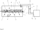
- Figure 1 shows a fluid-bed granulator system according to the state of the art
- Figure 2 shows a fluid-bed granulator system according to the invention
- Figure 1 shows a fluid-bed granulator system according to the state of the art comprising a fluid-bed granulator (14) with a granulator space (1) inside the fluid-bed granulator (14) and a perforated plate (2) located inside the granulator space (1).
- Spray nozzles (3) are located on or above the perforated plate (2), a fluidization air inlet (15) is located below the perforated plate (2).
- Multiple supply lines for atomization air (4) and supply lines for a liquid melt (5) are connected to the spray nozzles (3).
- the granulator further comprises a granulation seeds inlet (6), preferably in connection with a not shown product sieve or crusher, a granulator outlet opening (7) and an air vent opening (8).
- the fluid-bed (17) is formed by the corresponding granular particles (16) utilizing the fluidization air from below the perforated plate (2).
- the fluidization air flow is indicated by arrows labeled (II)
- the flow direction of the fluid bed granular particles (16) is indicated by arrows labeled (I).
- the fluid-bed (17) is preferably divided by one or more separating walls (22).
- the fluid-bed granulator system further comprises a scrubber unit (9) and a connection-duct (10) between the air vent opening (8) and the scrubber unit (9).
- the scrubber unit (9) comprises at least one (not shown) dust scrubber and one ammonia scrubber (not shown).
- a connection-duct (10) connects the fluid-bed granulator (14) with the scrubber unit (9) via the vent opening (8) and the scrubber opening (23).
- a cleaning nozzle (13) is located near the vent opening (8) at (d i ), prohibiting the adhesion, caking and blocking of the inner connection-duct (10) by urea dust in this area by spraying water in the direction of the air vent opening (8).
- part of the water and urea dust clusters may drop into the fluid-bed (17). This may disturb the homogeneous particle grow and air flow. The water flow will lead to large scale agglomeration inside the fluid-bed granulator, thereby obstructing proper operation of the fluid bed-granulator.
- Figure 2 shows a fluid-bed granulator system according to the invention.
- the principal setup is identical with the fluid-bed granulator system setup described in figure 1 .
- the inner surface of the connection-duct (10) is at least partially coated with an anti-adhesion layer (11) comprising an organic silicon compound.
- the anti-adhesion layer (11) prohibits or reduces the adhesion, caking and blocking of urea dust in the connection-duct. Therefore, the cleaning nozzle (13) can be either omitted or be placed more remote to the air vent opening (8) at (d i ), preferably in a vertical section of the connection-duct (10). This before mentioned positioning of the cleaning nozzle or nozzles (13) omits the need to spray water near the air vent opening (8).
- the cleaning nozzle (13) can be used to quench the hot air stream originating from the granulator space (1) of the fluid-bed granulator (14). Therefore the temperature of the before mentioned hot air stream can be reduced before entering the scrubbing unit (9), omitting or reducing additional quenching steps.
Landscapes
- Chemical & Material Sciences (AREA)
- Organic Chemistry (AREA)
- Chemical Kinetics & Catalysis (AREA)
- Life Sciences & Earth Sciences (AREA)
- Pest Control & Pesticides (AREA)
- Fertilizers (AREA)
- Glanulating (AREA)
- Devices And Processes Conducted In The Presence Of Fluids And Solid Particles (AREA)
Description
- The invention relates to a fluid-bed granulator with a coated vent duct, a plant comprising a fluid-bed granulator with a coated vent duct and the use of the fluid-bed granulator for the production of fertilizer granules.
- Due to a continuous world population growth, there is an ongoing need in providing reliable, easy producible and cheap fertilizers. These conventional fertilizers may contain nitrogen, phosphate, sulfur, potassium or micronutrients.
- A common, widely used fertilizer contains urea as its main component. The water soluble urea rapidly decomposes in the soil, providing ammonia and nitrate compounds. Based on the application, the fertilizer may contain only urea or a combination of urea with one or more of the before mentioned components, e.g. phosphate, sulfur, potassium or micronutrients.
- Urea can be produced on a large industrial scale by reacting ammonia with carbon dioxide via a (simplified) two-step reaction:


- Solid urea particles, as required for fertilizer applications, are produced in a finishing section e.g. by granulation, prilling or crystallization. The absorbance of water due to the hygroscopic nature of urea easily results in uncontrolled aggregation, quality degradation and caking of fine, untreated urea particles. This process can negatively affect the solubility, bulk storage, durability or chemical stability of the urea fertilizer. In addition, the uncontrolled gain in weight by absorbing water increases the transport weight and costs. Therefore, further post synthesis process steps are necessary in order to provide a transportable and storable urea fertilizer. Common technical processes include diverse solidification processes like prilling, drum granulation or fluid-bed granulation. Especially the prilling processes suffer from some critical drawbacks like relatively soft particles and sometimes deformed inhomogeneous particles.
- These problems can be avoided by using a fluid-bed granulation process, which results in harder, more stable and homogeneous granules. The resulting granular urea is particularly suitable for bulk transportation and blending operations. Furthermore, there is reduced segregation or mechanical damage during mixing and transporting of the urea based fertilizer.
- Examples of fluid-bed granulation process of urea can be found in
WO 2010/060535 A1 , e.g. in paragraphs [0025]-[0035],figure 1 or inUS 4,701,353 A ,DE 31 16 778 A1 andUS 4,219,589 A . - Urea fertilizers can be combined with ammonium sulfate or elemental sulfur, therefore providing both plant nutrients nitrogen and sulfur in one fertilizer. Ammonia sulfur can be directly used by the plant, whereas elemental sulfur needs to be decomposed by soil microorganisms, thereby providing long-term plant nutrients. Examples of urea/sulfur granules can be found e.g. in
US 4,330,319 A . - The fluid-bed granulation process is based on providing granulation seeds, which grow by absorbing very small droplets of a growth liquid. These small droplets can be provided via an "atomized" liquid urea melt. The term "atomized" used in the description refers to a mixing process of the liquid urea melt (or other suitable fertilizer melts) with a pressurized medium like air. This mixing process creates a liquid/gas emulsion or an aerosol of small droplets. The term "atomized" should therefore not be confused with a molecular separating process of atomic/covalent bonds. The produced droplets may have a medium size distribution around 1 µm to 200 µm. These small melt droplets are absorbed on the surface of the granulation seeds, thereby creating "growing" granulation particles. These fresh "in-situ" produced granules may commonly exhibit temperatures over 100 °C and are relatively soft. The particles further cool down in the fluid-bed of the granulator and/or in separate cooling compartments.
- However, the in-situ produced warm particles show a significant adhesion/wetting affinity. This adhesion may result in the before mentioned caking or even a (partiality) adsorption of urea granules on the granulator walls. This adsorption process of granules may even lead to a partial or total blocking of the fluid-bed granulator walls, vent openings and ducts. This blocking requires extensive cleaning measures or even complete shutdowns of the fluid-bed granulator.
-
GB 1,395,906 A -
DD 118 287 -
EP 2 832 439 A1 - It is therefore an objective of the present invention to provide a fluid-bed granulation or fluid-bed cooling system with a decreased anti-wetting or anti-caking tendency without the necessity of a complete granulator coating.
- The object of the present invention is solved by a fluid-bed granulation system according to
claim 1. Preferred embodiments of the invention are subject to the corresponding dependent claims. - It is another object of the present invention to provide a urea granulation plant. Preferred embodiments of the invention are subject to the corresponding dependent claims.
- In a further aspect it is another object of the present invention to provide the use of the fluid-bed granulator system or the fluid-bed cooler system for the production of fertilizer granules.
- The fluid-bed granulator system comprises a fluid-bed granulator with an air vent opening. Dust, e.g. urea dust, and chemical vapors like ammonia, which are created or released during the granulation process, are removed in a scrubber unit. Preferably, the scrubber unit comprises at least a dust removing scrubber and an ammonia removing scrubber. Examples of suitable scrubbers can be found in
WO 2005/032696 A1 (figure 1 ) orWO2010/60535 A1 minus 10 degree to 170 degree, more preferably in the range from plus/minus 30 degree to 120 degree. - Preferably the fluid-bed granulator comprises at least a granulator space inside the fluid-bed granulator. The fluid-bed granulator further comprises a perforated plate located inside the granulator space and spray nozzles located in, on, above or beside the perforated plate. Preferably, the spray nozzles are attached to the perforated plate. A fluidization air inlet, preferably located below the perforated plate, provides the necessary fluidization air for the fluid bed of fertilizer granules. The term "fluidization air" includes air or inert gases like carbon dioxide (CO2), nitrogen, argon or mixtures thereof. The spray nozzles are connected with supply lines for atomization air and supply lines for a liquid melt, preferably a liquid melt containing urea. Optionally, these supply lines for air and melt can be combined in one line. In addition, the fluid-bed granulator comprises a granulation seeds inlet. The term "a granulation seeds inlet" comprises internal and external devices, lines and openings for the introduction of granular seeds. The term "internal" refers to the production of granular seeds within the granulator. The term "external" refers to the provision or production of granular seeds from outside the granulator, e.g. via sieves or crushers outside the fluid-bed granulator. Furthermore the fluid-bed granulator comprises a granulator outlet opening and the air vent opening. The position of the air-vent opening is not fixed within the fluid-bed granulator. Preferably the air-vent opening is placed next to and/or above the granulation seeds inlet. Optionally, the granulator space comprises separating walls, optionally with integrated openings. These separating walls may further alter and modify the speed of the fluid bed towards the granulator outlet opening.
- Preferably, the anti-adhesion layer comprises an organic silicon compound. These silicon compounds effectively reduce the dust adhesion in the connection-duct and prevent/reduce the build-up of obstructing solid matter in the connection-duct. Examples of suitable coating procedures with organic silicon compounds, e.g. based on methylpolysiloxane, can be found in
EP 2 832 439 A1 - According to a preferred embodiment, at least 10 %, preferably at least 30 %, more preferably at least 50 %, of the inner surface of the connection-duct is coated with the anti-adhesion layer.
- In a further embodiment of the fluid-bed granulator a cleaning nozzle, preferably 1 to 6 cleaning nozzles, is/are located inside the connection-duct. The cleaning nozzle comprises nozzles types suitable for spraying water, providing additional cleaning means in the connection-duct. Optionally, more than one cleaning nozzle is located inside the connection-duct. Preferably the cleaning nozzles are arranged alongside the air flow direction and/or orthogonal to the air flow. Furthermore, the cleaning nozzles enable a suitable cooling of the dust and gas streams inside the connection-duct, thereby reducing the temperature of the gas/dust in the connection-duct and the scrubber unit.
- Preferably, the cleaning nozzle is located at a place/space within 2 % to 90 %, preferably between 5 % to 50 %, of the in-duct distance between the air vent opening and the scrubber unit inside the connection-duct. The term "in-duct distance" refers to the distance within the connection-duct measured from the air vent opening to the scrubber unit. Thereby, the relative value "0 %" refers directly to the air vent opening. The relative value "100 %" refers to the complete (before mentioned) in-duct distance, ending at the scrubber unit inlet. Thereby, d0 defines a starting point at the vent opening and d100 defines an end point at scrubber opening. Therefore, a relative in-duct position, e.g. of the cleaning nozzles, within the inner space of the connection-duct is preferably indicated as di.
- Surprisingly, the inventive coating enables a far more remote placement, indicated as di and referring to the vent opening of the cleaning nozzle in the connection-duct. This remote placement within a space of between 2 % (d2) to 90 % (d90) in-duct distance prohibits a reflux of cleaning liquids from a cleaning nozzle to the fluid granulator, more preferably in a vertical section of the connection-duct, thereby effectively preventing any reflux into the granulator space. This before mentioned reflux of cleaning liquids into the fluid-bed granulator would otherwise occur if the cleaning nozzles would be placed near the vent-opening of the connection-duct. On the other hand, a non-coated connection-duct requires cleaning means, e.g. a cleaning nozzle, located near the vent opening, outside the before mentioned space of between 2 % (d10) to 90 % (d90) of the in-duct distance, in order to remove a urea dust adhesion and avoid a complete connection-duct blocking.
- According to a preferred embodiment, the cleaning nozzle is located in a vertical section or horizontal section the of connection-duct, thereby prohibiting a reflux of the cleaning liquid into the granulator space. Preferably, the term "vertical" refers to the granular flow direction, describing a section of the connection-duct arranged approximately (preferably within a deviation of plus/minus 15 degree) orthogonal to the granular flow direction. Preferably the term "horizontal" to the granular flow direction, describing a section of the connection-duct arranged approximately (preferably within a deviation of plus/minus 15 degree) with the granular flow direction.
- In a preferred embodiment, the organic silicon compound comprises polyalkylsilicone compounds, polyarylsilicone compounds, polyallylsilicone compounds and/or mixtures or derivatives of alkyl-, aryl-und allyl silicone compounds.
- Preferably, the organic silicon compound comprises polyalkylsiloxane, polymethylsiloxane, polydimethylsiloxane, polymethylphenylsiloxane, (poly-)perfluoroalkylsilane or (poly-) perfluoroalkylsiloxane and/or mixtures or derivatives thereof, more preferably the organic silicon compound comprises polymethylsiloxane.
- In a further preferred embodiment, the anti-adhesion layer, preferably comprising an organic silicon compound, has a thickness of 0.5 µm to 1000 µm, preferably 15 µm to 40 µm.
- Preferably, the scrubber unit comprises a dust removing scrubber and an ammonia removing scrubber. Examples of suitable scrubbers can be found in
WO 2005/032696 A1 (figure 1 ),WO2010/60535 A1 figure 1 , paragraphs [0025] to [0030]),WO 2015/072854 A1 orEP 0 177 998 A1 . In a preferred embodiment, the dust scrubber utilizes a dilute urea solution to remove dust, small urea or other product particles. Very small particles like aerosols can be optionally removed according toWO2014/094987 A1 , e.g. paragraphs [0025], [0026] andfigure 2 . - In a preferred embodiment, the perforated plate is at least partially coated with the anti-adhesion layer, preferably comprising an organic silicon compound. By combining the coated inventive vent-duct and a coated perforated plate, the overall caking tendency in fluid-bed granulator is further decreased.
- The invention further comprises an inventive fluid-bed granulator system as previously disclosed for the production of fertilizer granules containing ammonia compounds, nitrates, phosphates, urea, elemental sulfur, ammonia sulfate, UAS (urea - ammonia sulfate), and/or mixtures thereof.
- The invention is further described in the following example. The example is meant for illustrative purpose only and does not restrict the scope of protection.
- Metallic granulator wall plates (size DIN A4) were coated (one half of the plate) with one of three different coatings based on silicon dioxide (SiO2), perfluoralkylsilane and polymethylsiloxan. The coated metallic granulator wall plates were placed inside a running fluid-bed granulator producing urea granules for 19, 20 and 17 day respectively. Afterwards, the metallic plates were optically inspected by comparing the coated and non-coated parts of the metallic plates. The averaged results are summarized in table 1 below. A weak or no urea adhesion is indicated with (++), a medium adhesion of urea is indicated with (O) and a strong adhesion is indicated with (-).
Table 1: degree of urea adhesion coating degree of urea adhesion silicon dioxide 0 perfluoroalkylsilane - polymethylsiloxane ++ - As shown in table 1, a polymethylsiloxane coating effectively prevents the adhesion of urea granules on the inspected surface. As mentioned before, this effect enables a relocation of the cleaning nozzle within the connection-duct from the vent-opening to the space of 2 % to 90 % of the in-duct distance between the air vent opening and the scrubber unit.
- The connection-duct of a fluid-bed granulator (as basically described in
Figure 1 and2 ) was coated with an anti-adhesion layer according to the invention. The connection-duct was coated starting from the air vent opening to the first connection-duct bending (approximately 90 ° (degree) change of the flow direction, preferably within a range of 70 degree to 120 degree). The overall testing period was one year. During this time span no falling dust lumps were detected. Without a coating according to the invention, falling dust lumps were detected during the year, especially after an extended running time. These falling dust lumps can result in damages in the fluid-bed granulator, especially falling dust lumps may damage the perforated plate.(++ strong urea dust accumulation/ + weaker urea dust accumulation; measured by optical inspection, (1) estimated based on dust accumulation after 53 days) Days Without coating Coated connection duct 33 ++(1) + 45 ++(1) + - An anti-adhesive coating according to the invention significantly lowers the numbers of fluid-bed granulator shut-downs. These shut-downs require a production stop and a complicated clean up of the connection-duct. Contrary to previous experiences, it is not necessary to coat the whole inner space of the fluid-bed granulator as described in
e.g. EP 2 832 439 A1 . On the other hand, an anti-adhesive coating according to the present invention alone is sufficient to significantly reduce the appearance of falling dust lumps and the number of fluid-bed granulator shut-downs. Therefore the invention at hand significantly reduces the coating cost (whole space versus selected single space) of the anti-adhesive coating and the overall amount of (precursor) coating chemicals in comparison to the state of the art. - The invention is further described in the following figures. The figures are meant for illustrative purpose only and do not restrict the scope of protection. The figures are not true to scale.
-
Figure 1 shows a fluid-bed granulator system according to the state of the art, -
Figure 2 shows a fluid-bed granulator system according to the invention and -
Figure 1 shows a fluid-bed granulator system according to the state of the art comprising a fluid-bed granulator (14) with a granulator space (1) inside the fluid-bed granulator (14) and a perforated plate (2) located inside the granulator space (1). Spray nozzles (3) are located on or above the perforated plate (2), a fluidization air inlet (15) is located below the perforated plate (2). Multiple supply lines for atomization air (4) and supply lines for a liquid melt (5) are connected to the spray nozzles (3). The granulator further comprises a granulation seeds inlet (6), preferably in connection with a not shown product sieve or crusher, a granulator outlet opening (7) and an air vent opening (8). The fluid-bed (17) is formed by the corresponding granular particles (16) utilizing the fluidization air from below the perforated plate (2). The fluidization air flow is indicated by arrows labeled (II), the flow direction of the fluid bed granular particles (16) is indicated by arrows labeled (I). The fluid-bed (17) is preferably divided by one or more separating walls (22). The fluid-bed granulator system further comprises a scrubber unit (9) and a connection-duct (10) between the air vent opening (8) and the scrubber unit (9). Preferably, the scrubber unit (9) comprises at least one (not shown) dust scrubber and one ammonia scrubber (not shown). A connection-duct (10) connects the fluid-bed granulator (14) with the scrubber unit (9) via the vent opening (8) and the scrubber opening (23). A cleaning nozzle (13) is located near the vent opening (8) at (di), prohibiting the adhesion, caking and blocking of the inner connection-duct (10) by urea dust in this area by spraying water in the direction of the air vent opening (8). However, part of the water and urea dust clusters may drop into the fluid-bed (17). This may disturb the homogeneous particle grow and air flow. The water flow will lead to large scale agglomeration inside the fluid-bed granulator, thereby obstructing proper operation of the fluid bed-granulator. -
Figure 2 shows a fluid-bed granulator system according to the invention. The principal setup is identical with the fluid-bed granulator system setup described infigure 1 . However the inner surface of the connection-duct (10) is at least partially coated with an anti-adhesion layer (11) comprising an organic silicon compound. The anti-adhesion layer (11) prohibits or reduces the adhesion, caking and blocking of urea dust in the connection-duct. Therefore, the cleaning nozzle (13) can be either omitted or be placed more remote to the air vent opening (8) at (di), preferably in a vertical section of the connection-duct (10). This before mentioned positioning of the cleaning nozzle or nozzles (13) omits the need to spray water near the air vent opening (8). Simultaneously, the amount of water and urea dust clusters dropping back into the fluid-bed (17) is significantly reduced, leading to longer/extended operation cycles and better product quality. In addition the cleaning nozzle (13) can be used to quench the hot air stream originating from the granulator space (1) of the fluid-bed granulator (14). Therefore the temperature of the before mentioned hot air stream can be reduced before entering the scrubbing unit (9), omitting or reducing additional quenching steps. -
- (1)
- granulator space
- (2)
- perforated plate
- (3)
- spray nozzles
- (4)
- supply lines for atomization air
- (5)
- supply lines for a liquid melt
- (6)
- granulation seeds inlet
- (7)
- granulator outlet opening
- (8)
- air vent opening
- (9)
- scrubber unit
- (10)
- connection-duct
- (11)
- anti-adhesion layer
- (12)
- inner surface of the connection-duct
- (13)
- cleaning nozzle
- (14)
- fluid-bed granulator
- (15)
- fluidization air inlet
- (16)
- granular particles
- (17)
- fluid-bed
- (22)
- separating walls
- (23)
- scrubber opening
- (d0)
- relative in-duct distance at the air vent opening
- (di)
- relative in-duct distance at a given point, e.g. position of the cleaning nozzle
- (d100)
- relative in-duct distance at the scrubber opening
- (I)
- flow direction of the granules
- (II)
- flow direction of fluidization air
Claims (14)
- Fluid-bed granulator system at least comprising:- a fluid-bed granulator (14) ,- a scrubber unit (9) and- a connection-duct (10) between an air vent opening (8) of the fluid-bed granulator (14) and the scrubber unit (9),wherein an inner surface of the connection-duct (10) is at least partially coated with an anti-adhesion layer (11).
- Fluid-bed granulator system according to claim 1, wherein the fluid-bed granulator comprises a granulator space (1) inside the fluid-bed granulator (14), a perforated plate (2) located inside the granulator space (1), spray nozzles (3) located in, on or beside the perforated plate (2), fluidization air inlet (15), supply lines for atomization air (4) connected to the spray nozzles (3), supply lines for a liquid melt (5) connected to the spray nozzles (3), a granulation seeds inlet (6), a granulator outlet opening (7) and the air vent opening (8).
- Fluid-bed granulator system according to claim 1 or 2, wherein the anti-adhesion layer (11) comprises an organic silicon compound.
- Fluid-bed granulator system according to any one of the claims 1 to 3, wherein at least 10 %, preferably at least 30 %, more preferably at least 50 %, of an inner surface (12) of the connection-duct (10) is coated with the anti-adhesion layer (11).
- Fluid-bed granulator system according to any one of the claims 1 to 4, wherein a cleaning nozzle (13) is located inside the connection-duct (10), preferably 1 to 6 cleaning nozzles (13) are located inside the connection-duct (10).
- Fluid-bed granulator system according to claim 5, wherein the cleaning nozzle (13) is located at a place/space within 2 % to 90 %, preferably between 5 % to 50 %, of the in-duct distance between the air vent opening (8) and the scrubber unit (9) inside the connection-duct (10).
- Fluid-bed granulator system according to claim 5 or 6, wherein the cleaning nozzle (13) is located in a vertical section of connection-duct (10).
- Fluid-bed granulator system according to any one of the claims 3 to 7, wherein the organic silicon compound comprises polyalkylsilicone compounds, polyarylsilicone compounds, polyallylsilicone compounds and/or mixtures or derivatives of alkyl-, aryl- und allyl silicone compounds.
- Fluid-bed granulator system according to claim 8, wherein the organic silicon compound comprises polyalkylsiloxane, polymethylsiloxane, polydimethylsiloxane, polymethylphenylsiloxane, perfluoroalkylsilane or perfluoroalkylsiloxane and/or mixtures or derivatives thereof.
- Fluid-bed granulator system according to claim 9, wherein the organic silicon compound comprises polymethylsiloxane.
- Fluid-bed granulator system according to any one of the claims 1 to 10, wherein the anti-adhesion layer (11) has a thickness of 0.5 µm to 1000 µm, preferably 10 µm to 40 µm.
- Fluid-bed granulator system according to any one of the claims 2 to 11, wherein the perforated plate (2) is at least partially coated with the anti-adhesion layer (11).
- Urea granulation plant comprising a fluid-bed granulator system according to any one of the claims 1 to 12.
- Use of the Fluid-bed granulator system according to any one of the claims 1 to 12 for the production of fertilizer granules containing ammonia compounds, nitrates, phosphates, urea, elemental sulfur, ammonia sulfate, UAS (urea - ammonia sulfate), and/or mixtures thereof.
Applications Claiming Priority (3)
| Application Number | Priority Date | Filing Date | Title |
|---|---|---|---|
| EP18163504 | 2018-03-23 | ||
| EP18175723 | 2018-06-04 | ||
| PCT/EP2019/057111 WO2019180155A1 (en) | 2018-03-23 | 2019-03-21 | Fluid-bed granulator system with coating material to prevent dust buildup in the air systems of urea granulation plants |
Publications (2)
| Publication Number | Publication Date |
|---|---|
| EP3768416A1 EP3768416A1 (en) | 2021-01-27 |
| EP3768416B1 true EP3768416B1 (en) | 2022-11-09 |
Family
ID=65818025
Family Applications (1)
| Application Number | Title | Priority Date | Filing Date |
|---|---|---|---|
| EP19711917.5A Active EP3768416B1 (en) | 2018-03-23 | 2019-03-21 | Fluid-bed granulator system with coating material to prevent dust buildup in the air systems of urea granulation plants |
Country Status (5)
| Country | Link |
|---|---|
| US (1) | US12065389B2 (en) |
| EP (1) | EP3768416B1 (en) |
| JP (2) | JP2021516154A (en) |
| PL (1) | PL3768416T3 (en) |
| WO (1) | WO2019180155A1 (en) |
Families Citing this family (2)
| Publication number | Priority date | Publication date | Assignee | Title |
|---|---|---|---|---|
| JP7402714B2 (en) | 2020-03-05 | 2023-12-21 | 東洋エンジニアリング株式会社 | Fluidized bed granulator or fluidized bed/entrained bed granulator |
| EP4363093A4 (en) * | 2021-06-29 | 2025-05-07 | ArrMaz Products Inc. | Rosin-based sustainable dust, caking, and moisture control coatings |
Family Cites Families (23)
| Publication number | Priority date | Publication date | Assignee | Title |
|---|---|---|---|---|
| DE118287C (en) | ||||
| US3378240A (en) * | 1966-08-01 | 1968-04-16 | Kinney Eng Inc S P | Furnace gas cleaning and cooling apparatus |
| GB1395906A (en) | 1971-05-08 | 1975-05-29 | Fisons Ltd | Prilling |
| US3853506A (en) * | 1971-10-18 | 1974-12-10 | Purity Corp | Pollution control apparatus and method |
| JPS543104B2 (en) | 1973-12-28 | 1979-02-17 | ||
| DD118287A1 (en) | 1975-02-14 | 1976-02-20 | ||
| GB1581761A (en) | 1977-06-09 | 1980-12-17 | Azote Sa Cie Neerlandaise | Urea granulation |
| NL191557C (en) | 1980-05-12 | 1995-09-19 | Azote Sa Cie Neerlandaise | A method for manufacturing granules built up from a core and an envelope. |
| CA1144771A (en) | 1980-12-24 | 1983-04-19 | Cominco Ltd. | Manufacture of urea sulfur fertilizer |
| NL8303000A (en) | 1983-08-27 | 1985-03-18 | Unie Van Kunstmestfab Bv | METHOD FOR PREPARING GRANULES |
| NL8402782A (en) | 1984-09-12 | 1986-04-01 | Stamicarbon | METHOD FOR REMOVING PARTICLES FROM A GASEOUS MEDIUM |
| CH666828A5 (en) | 1985-12-30 | 1988-08-31 | Aeromatic Ag | Device for producing and / or editing granules. |
| JP3579804B2 (en) | 1995-07-12 | 2004-10-20 | 不二パウダル株式会社 | Screw for screw extrusion granulator |
| JP3456355B2 (en) * | 1996-11-27 | 2003-10-14 | チッソ株式会社 | Granule coating apparatus and granule coating method |
| JP3226817B2 (en) | 1996-12-11 | 2001-11-05 | 日鐵建材工業株式会社 | Hollow granule mold flux manufacturing equipment |
| DE19826570C2 (en) | 1998-06-15 | 2002-10-31 | Piesteritz Stickstoff | Process for the production of fertilizer granules containing urea and ammonium sulfate |
| DE10346519A1 (en) | 2003-10-02 | 2005-05-04 | Uhde Gmbh | Process for the removal of ammonia and dust from an exhaust gas resulting from the production of fertilizers |
| US7908765B2 (en) * | 2006-12-22 | 2011-03-22 | Collette Nv | Continuous granulating and drying apparatus |
| JP4455643B2 (en) | 2007-10-30 | 2010-04-21 | 東洋エンジニアリング株式会社 | Granulating apparatus and granulating method using the same |
| EP2192099A1 (en) * | 2008-11-28 | 2010-06-02 | Uhde Fertilizer Technology B.V. | Urea granulation process with an acidic scrubbing system and the subsequent integration of ammonium salt into urea granules |
| EP2746244A1 (en) | 2012-12-21 | 2014-06-25 | Uhde Fertilizer Technology B.V. | Method for reducing the visible downwind detached plume opacity |
| EP2832439A1 (en) * | 2013-08-01 | 2015-02-04 | Uhde Fertilizer Technology B.V. | Reactor for producing nitrogen-containing fertilizer granules |
| HRP20241330T1 (en) | 2013-11-15 | 2024-12-20 | Stamicarbon B.V. | DEVICE AND METHOD FOR CAPTURING PARTICLES FROM A GAS STREAM AND METHOD FOR REMOVING SOLUBLE PARTICLES FROM A GAS |
-
2019
- 2019-03-21 US US16/981,740 patent/US12065389B2/en active Active
- 2019-03-21 WO PCT/EP2019/057111 patent/WO2019180155A1/en not_active Ceased
- 2019-03-21 EP EP19711917.5A patent/EP3768416B1/en active Active
- 2019-03-21 PL PL19711917.5T patent/PL3768416T3/en unknown
- 2019-03-21 JP JP2020550080A patent/JP2021516154A/en active Pending
-
2022
- 2022-12-22 JP JP2022205191A patent/JP7578668B2/en active Active
Also Published As
| Publication number | Publication date |
|---|---|
| JP2021516154A (en) | 2021-07-01 |
| EP3768416A1 (en) | 2021-01-27 |
| WO2019180155A1 (en) | 2019-09-26 |
| US12065389B2 (en) | 2024-08-20 |
| PL3768416T3 (en) | 2023-03-06 |
| JP7578668B2 (en) | 2024-11-06 |
| US20210114948A1 (en) | 2021-04-22 |
| JP2023030102A (en) | 2023-03-07 |
Similar Documents
| Publication | Publication Date | Title |
|---|---|---|
| CN103189335B (en) | For the production of the method with the urea fertilizer that low moisture absorption tends to | |
| CA2120618C (en) | Apparatus and process for coating particles | |
| EP2748124B1 (en) | Process for producing a coated fertilizer | |
| JP7201708B2 (en) | Internal cooling system for fluidized bed granulation plant | |
| JP7578668B2 (en) | Fluid bed granulator system with coating material to prevent dust accumulation in the air system of urea granulation plant | |
| EP3784639B1 (en) | Urea production plant and scrubbing system | |
| JP5065271B2 (en) | Method for producing urea pellets | |
| US20160175797A1 (en) | Reactor for producing nitrogen-containing fertilizer granules | |
| CA3069894C (en) | Improved urea finishing processes comprising heated and/or thermally insulated conduits for minimizing clogging of off-gas pipes | |
| JP7083904B2 (en) | Baffle in fluidized bed cooler | |
| WO2019180186A1 (en) | Divided perforated plate for fluid bed granulator or cooler | |
| EA041687B1 (en) | INTERNAL COOLING SYSTEM FOR FLUID BED GRANULATION PLANTS | |
| JPS6058193B2 (en) | Fluid granulation method for urea |
Legal Events
| Date | Code | Title | Description |
|---|---|---|---|
| STAA | Information on the status of an ep patent application or granted ep patent |
Free format text: STATUS: UNKNOWN |
|
| STAA | Information on the status of an ep patent application or granted ep patent |
Free format text: STATUS: THE INTERNATIONAL PUBLICATION HAS BEEN MADE |
|
| PUAI | Public reference made under article 153(3) epc to a published international application that has entered the european phase |
Free format text: ORIGINAL CODE: 0009012 |
|
| STAA | Information on the status of an ep patent application or granted ep patent |
Free format text: STATUS: REQUEST FOR EXAMINATION WAS MADE |
|
| 17P | Request for examination filed |
Effective date: 20201023 |
|
| AK | Designated contracting states |
Kind code of ref document: A1 Designated state(s): AL AT BE BG CH CY CZ DE DK EE ES FI FR GB GR HR HU IE IS IT LI LT LU LV MC MK MT NL NO PL PT RO RS SE SI SK SM TR |
|
| AX | Request for extension of the european patent |
Extension state: BA ME |
|
| RAP1 | Party data changed (applicant data changed or rights of an application transferred) |
Owner name: THYSSENKRUPP AG Owner name: THYSSENKRUPP FERTILIZER TECHNOLOGY GMBH |
|
| DAV | Request for validation of the european patent (deleted) | ||
| DAX | Request for extension of the european patent (deleted) | ||
| GRAP | Despatch of communication of intention to grant a patent |
Free format text: ORIGINAL CODE: EPIDOSNIGR1 |
|
| STAA | Information on the status of an ep patent application or granted ep patent |
Free format text: STATUS: GRANT OF PATENT IS INTENDED |
|
| INTG | Intention to grant announced |
Effective date: 20220112 |
|
| GRAJ | Information related to disapproval of communication of intention to grant by the applicant or resumption of examination proceedings by the epo deleted |
Free format text: ORIGINAL CODE: EPIDOSDIGR1 |
|
| STAA | Information on the status of an ep patent application or granted ep patent |
Free format text: STATUS: REQUEST FOR EXAMINATION WAS MADE |
|
| GRAP | Despatch of communication of intention to grant a patent |
Free format text: ORIGINAL CODE: EPIDOSNIGR1 |
|
| STAA | Information on the status of an ep patent application or granted ep patent |
Free format text: STATUS: GRANT OF PATENT IS INTENDED |
|
| INTC | Intention to grant announced (deleted) | ||
| INTG | Intention to grant announced |
Effective date: 20220614 |
|
| GRAS | Grant fee paid |
Free format text: ORIGINAL CODE: EPIDOSNIGR3 |
|
| GRAA | (expected) grant |
Free format text: ORIGINAL CODE: 0009210 |
|
| STAA | Information on the status of an ep patent application or granted ep patent |
Free format text: STATUS: THE PATENT HAS BEEN GRANTED |
|
| AK | Designated contracting states |
Kind code of ref document: B1 Designated state(s): AL AT BE BG CH CY CZ DE DK EE ES FI FR GB GR HR HU IE IS IT LI LT LU LV MC MK MT NL NO PL PT RO RS SE SI SK SM TR |
|
| REG | Reference to a national code |
Ref country code: GB Ref legal event code: FG4D |
|
| REG | Reference to a national code |
Ref country code: CH Ref legal event code: EP Ref country code: AT Ref legal event code: REF Ref document number: 1529996 Country of ref document: AT Kind code of ref document: T Effective date: 20221115 |
|
| REG | Reference to a national code |
Ref country code: DE Ref legal event code: R096 Ref document number: 602019021697 Country of ref document: DE |
|
| REG | Reference to a national code |
Ref country code: IE Ref legal event code: FG4D |
|
| REG | Reference to a national code |
Ref country code: NL Ref legal event code: FP |
|
| REG | Reference to a national code |
Ref country code: LT Ref legal event code: MG9D |
|
| REG | Reference to a national code |
Ref country code: AT Ref legal event code: MK05 Ref document number: 1529996 Country of ref document: AT Kind code of ref document: T Effective date: 20221109 |
|
| PG25 | Lapsed in a contracting state [announced via postgrant information from national office to epo] |
Ref country code: SE Free format text: LAPSE BECAUSE OF FAILURE TO SUBMIT A TRANSLATION OF THE DESCRIPTION OR TO PAY THE FEE WITHIN THE PRESCRIBED TIME-LIMIT Effective date: 20221109 Ref country code: PT Free format text: LAPSE BECAUSE OF FAILURE TO SUBMIT A TRANSLATION OF THE DESCRIPTION OR TO PAY THE FEE WITHIN THE PRESCRIBED TIME-LIMIT Effective date: 20230309 Ref country code: NO Free format text: LAPSE BECAUSE OF FAILURE TO SUBMIT A TRANSLATION OF THE DESCRIPTION OR TO PAY THE FEE WITHIN THE PRESCRIBED TIME-LIMIT Effective date: 20230209 Ref country code: LT Free format text: LAPSE BECAUSE OF FAILURE TO SUBMIT A TRANSLATION OF THE DESCRIPTION OR TO PAY THE FEE WITHIN THE PRESCRIBED TIME-LIMIT Effective date: 20221109 Ref country code: FI Free format text: LAPSE BECAUSE OF FAILURE TO SUBMIT A TRANSLATION OF THE DESCRIPTION OR TO PAY THE FEE WITHIN THE PRESCRIBED TIME-LIMIT Effective date: 20221109 Ref country code: ES Free format text: LAPSE BECAUSE OF FAILURE TO SUBMIT A TRANSLATION OF THE DESCRIPTION OR TO PAY THE FEE WITHIN THE PRESCRIBED TIME-LIMIT Effective date: 20221109 Ref country code: AT Free format text: LAPSE BECAUSE OF FAILURE TO SUBMIT A TRANSLATION OF THE DESCRIPTION OR TO PAY THE FEE WITHIN THE PRESCRIBED TIME-LIMIT Effective date: 20221109 |
|
| PG25 | Lapsed in a contracting state [announced via postgrant information from national office to epo] |
Ref country code: RS Free format text: LAPSE BECAUSE OF FAILURE TO SUBMIT A TRANSLATION OF THE DESCRIPTION OR TO PAY THE FEE WITHIN THE PRESCRIBED TIME-LIMIT Effective date: 20221109 Ref country code: LV Free format text: LAPSE BECAUSE OF FAILURE TO SUBMIT A TRANSLATION OF THE DESCRIPTION OR TO PAY THE FEE WITHIN THE PRESCRIBED TIME-LIMIT Effective date: 20221109 Ref country code: IS Free format text: LAPSE BECAUSE OF FAILURE TO SUBMIT A TRANSLATION OF THE DESCRIPTION OR TO PAY THE FEE WITHIN THE PRESCRIBED TIME-LIMIT Effective date: 20230309 Ref country code: HR Free format text: LAPSE BECAUSE OF FAILURE TO SUBMIT A TRANSLATION OF THE DESCRIPTION OR TO PAY THE FEE WITHIN THE PRESCRIBED TIME-LIMIT Effective date: 20221109 Ref country code: GR Free format text: LAPSE BECAUSE OF FAILURE TO SUBMIT A TRANSLATION OF THE DESCRIPTION OR TO PAY THE FEE WITHIN THE PRESCRIBED TIME-LIMIT Effective date: 20230210 |
|
| P01 | Opt-out of the competence of the unified patent court (upc) registered |
Effective date: 20230530 |
|
| PG25 | Lapsed in a contracting state [announced via postgrant information from national office to epo] |
Ref country code: SM Free format text: LAPSE BECAUSE OF FAILURE TO SUBMIT A TRANSLATION OF THE DESCRIPTION OR TO PAY THE FEE WITHIN THE PRESCRIBED TIME-LIMIT Effective date: 20221109 Ref country code: EE Free format text: LAPSE BECAUSE OF FAILURE TO SUBMIT A TRANSLATION OF THE DESCRIPTION OR TO PAY THE FEE WITHIN THE PRESCRIBED TIME-LIMIT Effective date: 20221109 Ref country code: DK Free format text: LAPSE BECAUSE OF FAILURE TO SUBMIT A TRANSLATION OF THE DESCRIPTION OR TO PAY THE FEE WITHIN THE PRESCRIBED TIME-LIMIT Effective date: 20221109 |
|
| REG | Reference to a national code |
Ref country code: DE Ref legal event code: R097 Ref document number: 602019021697 Country of ref document: DE |
|
| PG25 | Lapsed in a contracting state [announced via postgrant information from national office to epo] |
Ref country code: SK Free format text: LAPSE BECAUSE OF FAILURE TO SUBMIT A TRANSLATION OF THE DESCRIPTION OR TO PAY THE FEE WITHIN THE PRESCRIBED TIME-LIMIT Effective date: 20221109 Ref country code: AL Free format text: LAPSE BECAUSE OF FAILURE TO SUBMIT A TRANSLATION OF THE DESCRIPTION OR TO PAY THE FEE WITHIN THE PRESCRIBED TIME-LIMIT Effective date: 20221109 |
|
| PLBE | No opposition filed within time limit |
Free format text: ORIGINAL CODE: 0009261 |
|
| STAA | Information on the status of an ep patent application or granted ep patent |
Free format text: STATUS: NO OPPOSITION FILED WITHIN TIME LIMIT |
|
| 26N | No opposition filed |
Effective date: 20230810 |
|
| PG25 | Lapsed in a contracting state [announced via postgrant information from national office to epo] |
Ref country code: MC Free format text: LAPSE BECAUSE OF FAILURE TO SUBMIT A TRANSLATION OF THE DESCRIPTION OR TO PAY THE FEE WITHIN THE PRESCRIBED TIME-LIMIT Effective date: 20221109 |
|
| GBPC | Gb: european patent ceased through non-payment of renewal fee |
Effective date: 20230321 |
|
| PG25 | Lapsed in a contracting state [announced via postgrant information from national office to epo] |
Ref country code: SI Free format text: LAPSE BECAUSE OF FAILURE TO SUBMIT A TRANSLATION OF THE DESCRIPTION OR TO PAY THE FEE WITHIN THE PRESCRIBED TIME-LIMIT Effective date: 20221109 |
|
| REG | Reference to a national code |
Ref country code: BE Ref legal event code: MM Effective date: 20230331 |
|
| PG25 | Lapsed in a contracting state [announced via postgrant information from national office to epo] |
Ref country code: LU Free format text: LAPSE BECAUSE OF NON-PAYMENT OF DUE FEES Effective date: 20230321 |
|
| REG | Reference to a national code |
Ref country code: IE Ref legal event code: MM4A |
|
| PG25 | Lapsed in a contracting state [announced via postgrant information from national office to epo] |
Ref country code: GB Free format text: LAPSE BECAUSE OF NON-PAYMENT OF DUE FEES Effective date: 20230321 |
|
| PG25 | Lapsed in a contracting state [announced via postgrant information from national office to epo] |
Ref country code: IE Free format text: LAPSE BECAUSE OF NON-PAYMENT OF DUE FEES Effective date: 20230321 Ref country code: GB Free format text: LAPSE BECAUSE OF NON-PAYMENT OF DUE FEES Effective date: 20230321 Ref country code: FR Free format text: LAPSE BECAUSE OF NON-PAYMENT OF DUE FEES Effective date: 20230331 |
|
| PG25 | Lapsed in a contracting state [announced via postgrant information from national office to epo] |
Ref country code: BE Free format text: LAPSE BECAUSE OF NON-PAYMENT OF DUE FEES Effective date: 20230331 |
|
| PG25 | Lapsed in a contracting state [announced via postgrant information from national office to epo] |
Ref country code: BG Free format text: LAPSE BECAUSE OF FAILURE TO SUBMIT A TRANSLATION OF THE DESCRIPTION OR TO PAY THE FEE WITHIN THE PRESCRIBED TIME-LIMIT Effective date: 20221109 |
|
| PG25 | Lapsed in a contracting state [announced via postgrant information from national office to epo] |
Ref country code: BG Free format text: LAPSE BECAUSE OF FAILURE TO SUBMIT A TRANSLATION OF THE DESCRIPTION OR TO PAY THE FEE WITHIN THE PRESCRIBED TIME-LIMIT Effective date: 20221109 |
|
| REG | Reference to a national code |
Ref country code: DE Ref legal event code: R081 Ref document number: 602019021697 Country of ref document: DE Owner name: THYSSENKRUPP UHDE FERTILIZER TECHNOLOGY GMBH, DE Free format text: FORMER OWNERS: THYSSENKRUPP AG, 45143 ESSEN, DE; THYSSENKRUPP FERTILIZER TECHNOLOGY GMBH, 44141 DORTMUND, DE Ref country code: DE Ref legal event code: R081 Ref document number: 602019021697 Country of ref document: DE Owner name: THYSSENKRUPP AG, DE Free format text: FORMER OWNERS: THYSSENKRUPP AG, 45143 ESSEN, DE; THYSSENKRUPP FERTILIZER TECHNOLOGY GMBH, 44141 DORTMUND, DE |
|
| PGFP | Annual fee paid to national office [announced via postgrant information from national office to epo] |
Ref country code: CH Payment date: 20250401 Year of fee payment: 7 |
|
| PG25 | Lapsed in a contracting state [announced via postgrant information from national office to epo] |
Ref country code: CY Free format text: LAPSE BECAUSE OF FAILURE TO SUBMIT A TRANSLATION OF THE DESCRIPTION OR TO PAY THE FEE WITHIN THE PRESCRIBED TIME-LIMIT; INVALID AB INITIO Effective date: 20190321 |
|
| PG25 | Lapsed in a contracting state [announced via postgrant information from national office to epo] |
Ref country code: HU Free format text: LAPSE BECAUSE OF FAILURE TO SUBMIT A TRANSLATION OF THE DESCRIPTION OR TO PAY THE FEE WITHIN THE PRESCRIBED TIME-LIMIT; INVALID AB INITIO Effective date: 20190321 |
|
| PG25 | Lapsed in a contracting state [announced via postgrant information from national office to epo] |
Ref country code: TR Free format text: LAPSE BECAUSE OF FAILURE TO SUBMIT A TRANSLATION OF THE DESCRIPTION OR TO PAY THE FEE WITHIN THE PRESCRIBED TIME-LIMIT Effective date: 20221109 |
|
| REG | Reference to a national code |
Ref country code: CH Ref legal event code: U11 Free format text: ST27 STATUS EVENT CODE: U-0-0-U10-U11 (AS PROVIDED BY THE NATIONAL OFFICE) Effective date: 20260401 |
|
| PGFP | Annual fee paid to national office [announced via postgrant information from national office to epo] |
Ref country code: DE Payment date: 20260319 Year of fee payment: 8 |
|
| PGFP | Annual fee paid to national office [announced via postgrant information from national office to epo] |
Ref country code: RO Payment date: 20260316 Year of fee payment: 8 Ref country code: IT Payment date: 20260324 Year of fee payment: 8 |
|
| PGFP | Annual fee paid to national office [announced via postgrant information from national office to epo] |
Ref country code: NL Payment date: 20260319 Year of fee payment: 8 |
|
| PGFP | Annual fee paid to national office [announced via postgrant information from national office to epo] |
Ref country code: CZ Payment date: 20260317 Year of fee payment: 8 |
|
| PGFP | Annual fee paid to national office [announced via postgrant information from national office to epo] |
Ref country code: PL Payment date: 20260313 Year of fee payment: 8 |