EP3768331B1 - Device and its use for disinfecting pipelines - Google Patents
Device and its use for disinfecting pipelines Download PDFInfo
- Publication number
- EP3768331B1 EP3768331B1 EP19714303.5A EP19714303A EP3768331B1 EP 3768331 B1 EP3768331 B1 EP 3768331B1 EP 19714303 A EP19714303 A EP 19714303A EP 3768331 B1 EP3768331 B1 EP 3768331B1
- Authority
- EP
- European Patent Office
- Prior art keywords
- spray
- chain
- pipe
- spacers
- disinfectant
- Prior art date
- Legal status (The legal status is an assumption and is not a legal conclusion. Google has not performed a legal analysis and makes no representation as to the accuracy of the status listed.)
- Active
Links
Images

Classifications
-
- A—HUMAN NECESSITIES
- A61—MEDICAL OR VETERINARY SCIENCE; HYGIENE
- A61L—METHODS OR APPARATUS FOR STERILISING MATERIALS OR OBJECTS IN GENERAL; DISINFECTION, STERILISATION OR DEODORISATION OF AIR; CHEMICAL ASPECTS OF BANDAGES, DRESSINGS, ABSORBENT PADS OR SURGICAL ARTICLES; MATERIALS FOR BANDAGES, DRESSINGS, ABSORBENT PADS OR SURGICAL ARTICLES
- A61L2/00—Methods or apparatus for disinfecting or sterilising materials or objects other than foodstuffs or contact lenses; Accessories therefor
- A61L2/02—Methods or apparatus for disinfecting or sterilising materials or objects other than foodstuffs or contact lenses; Accessories therefor using physical phenomena
- A61L2/08—Radiation
- A61L2/10—Ultraviolet radiation
-
- A—HUMAN NECESSITIES
- A01—AGRICULTURE; FORESTRY; ANIMAL HUSBANDRY; HUNTING; TRAPPING; FISHING
- A01N—PRESERVATION OF BODIES OF HUMANS OR ANIMALS OR PLANTS OR PARTS THEREOF; BIOCIDES, e.g. AS DISINFECTANTS, AS PESTICIDES OR AS HERBICIDES; PEST REPELLANTS OR ATTRACTANTS; PLANT GROWTH REGULATORS
- A01N25/00—Biocides, pest repellants or attractants, or plant growth regulators, characterised by their forms, or by their non-active ingredients or by their methods of application, e.g. seed treatment or sequential application; Substances for reducing the noxious effect of the active ingredients to organisms other than pests
-
- A—HUMAN NECESSITIES
- A61—MEDICAL OR VETERINARY SCIENCE; HYGIENE
- A61L—METHODS OR APPARATUS FOR STERILISING MATERIALS OR OBJECTS IN GENERAL; DISINFECTION, STERILISATION OR DEODORISATION OF AIR; CHEMICAL ASPECTS OF BANDAGES, DRESSINGS, ABSORBENT PADS OR SURGICAL ARTICLES; MATERIALS FOR BANDAGES, DRESSINGS, ABSORBENT PADS OR SURGICAL ARTICLES
- A61L2/00—Methods or apparatus for disinfecting or sterilising materials or objects other than foodstuffs or contact lenses; Accessories therefor
- A61L2/16—Methods or apparatus for disinfecting or sterilising materials or objects other than foodstuffs or contact lenses; Accessories therefor using chemical substances
- A61L2/22—Phase substances, e.g. smokes, aerosols or sprayed or atomised substances
-
- A—HUMAN NECESSITIES
- A61—MEDICAL OR VETERINARY SCIENCE; HYGIENE
- A61L—METHODS OR APPARATUS FOR STERILISING MATERIALS OR OBJECTS IN GENERAL; DISINFECTION, STERILISATION OR DEODORISATION OF AIR; CHEMICAL ASPECTS OF BANDAGES, DRESSINGS, ABSORBENT PADS OR SURGICAL ARTICLES; MATERIALS FOR BANDAGES, DRESSINGS, ABSORBENT PADS OR SURGICAL ARTICLES
- A61L2/00—Methods or apparatus for disinfecting or sterilising materials or objects other than foodstuffs or contact lenses; Accessories therefor
- A61L2/26—Accessories or devices or components used for biocidal treatment
-
- B—PERFORMING OPERATIONS; TRANSPORTING
- B08—CLEANING
- B08B—CLEANING IN GENERAL; PREVENTION OF FOULING IN GENERAL
- B08B7/00—Cleaning by methods not provided for in a single other subclass or a single group in this subclass
- B08B7/0035—Cleaning by methods not provided for in a single other subclass or a single group in this subclass by radiant energy, e.g. UV, laser, light beam or the like
- B08B7/0057—Cleaning by methods not provided for in a single other subclass or a single group in this subclass by radiant energy, e.g. UV, laser, light beam or the like by ultraviolet radiation
-
- B—PERFORMING OPERATIONS; TRANSPORTING
- B08—CLEANING
- B08B—CLEANING IN GENERAL; PREVENTION OF FOULING IN GENERAL
- B08B9/00—Cleaning hollow articles by methods or apparatus specially adapted thereto
- B08B9/02—Cleaning pipes or tubes or systems of pipes or tubes
- B08B9/027—Cleaning the internal surfaces; Removal of blockages
- B08B9/04—Cleaning the internal surfaces; Removal of blockages using cleaning devices introduced into and moved along the pipes
- B08B9/043—Cleaning the internal surfaces; Removal of blockages using cleaning devices introduced into and moved along the pipes moved by externally powered mechanical linkage, e.g. pushed or drawn through the pipes
-
- B—PERFORMING OPERATIONS; TRANSPORTING
- B08—CLEANING
- B08B—CLEANING IN GENERAL; PREVENTION OF FOULING IN GENERAL
- B08B9/00—Cleaning hollow articles by methods or apparatus specially adapted thereto
- B08B9/08—Cleaning containers, e.g. tanks
-
- A61L2103/23—
-
- A—HUMAN NECESSITIES
- A61—MEDICAL OR VETERINARY SCIENCE; HYGIENE
- A61L—METHODS OR APPARATUS FOR STERILISING MATERIALS OR OBJECTS IN GENERAL; DISINFECTION, STERILISATION OR DEODORISATION OF AIR; CHEMICAL ASPECTS OF BANDAGES, DRESSINGS, ABSORBENT PADS OR SURGICAL ARTICLES; MATERIALS FOR BANDAGES, DRESSINGS, ABSORBENT PADS OR SURGICAL ARTICLES
- A61L2202/00—Aspects relating to methods or apparatus for disinfecting or sterilising materials or objects
- A61L2202/10—Apparatus features
- A61L2202/11—Apparatus for generating biocidal substances, e.g. vaporisers, UV lamps
-
- A—HUMAN NECESSITIES
- A61—MEDICAL OR VETERINARY SCIENCE; HYGIENE
- A61L—METHODS OR APPARATUS FOR STERILISING MATERIALS OR OBJECTS IN GENERAL; DISINFECTION, STERILISATION OR DEODORISATION OF AIR; CHEMICAL ASPECTS OF BANDAGES, DRESSINGS, ABSORBENT PADS OR SURGICAL ARTICLES; MATERIALS FOR BANDAGES, DRESSINGS, ABSORBENT PADS OR SURGICAL ARTICLES
- A61L2202/00—Aspects relating to methods or apparatus for disinfecting or sterilising materials or objects
- A61L2202/10—Apparatus features
- A61L2202/15—Biocide distribution means, e.g. nozzles, pumps, manifolds, fans, baffles, sprayers
Definitions
- the invention relates to a device for disinfecting the inner walls of pipelines, according to the preamble of claim 1.
- the disinfection of containers or structures disclosed below serves merely to illustrate the invention, but is not part of the claimed invention.
- biofilms of varying thickness form over time. These biofilms form on the inner wall of the pipe and serve as a living environment for microorganisms. As long as these biofilms are free of harmful germs and pathogens, this is not a problem.
- pathogenic germs bacteria and/or viruses such as Escherichia coli, enterococci, legionella or Pseudomonas aeruginosa
- fungi and their spores can also settle in these biofilms.
- These microorganisms can then multiply there and be flushed out with the water flowing through the pipe.
- These microorganisms can then reach the individual consumers (e.g. in the case of drinking water supply systems, to individual households) and pose a health risk to humans and animals.
- Disinfection involves putting a system into a state (environment) in which microorganisms are killed or damaged to such an extent that they are no longer expected to grow or multiply. Disinfection also means inactivating viruses if they are present. This state is generally limited in time and may need to be repeated again and again.
- aqueous disinfection solutions are fed into or passed through the components to be disinfected using the flow-through process or the stationary process.
- US5072487A discloses a device for disinfecting the interior of pipes, which comprises both nozzles and UV lamps.
- a spray chain is moved through the emptied and possibly pre-cleaned pipeline, which has at least one nozzle for dispensing and nebulizing the disinfectant and/or at least one source of UV light, in particular a UVC source.
- the spray chain (“spray” because of the spraying of mist and/or electromagnetic rays, the latter the more useful, the "harder") is, as explained in more detail below, constructed in such a way that the nozzle and/or Source distance from the bottom and the side walls of the pipe.
- the device according to the invention has a spray chain that is introduced into the pre-cleaned or uncleaned pipeline and activated there, thus releasing the disinfectant in a nebulized form and is controlled by a so-called operating drum.
- the spray chain can be pulled by a traction device (chain, rope, etc.) previously introduced into the pipeline, it can be attached to a (remote-controlled) vehicle, or moved in another way through the area to be cleaned.
- alcohol can also be introduced into the building using the spray and mist nozzles, which destroys the entire biofilm and prevents the pathogenic germs from multiplying and spreading.
- Spraying alcohol at high pressure also results in the biofilm being mechanically removed. Mechanical shearing is included, so to speak.
- UV treatment itself can be described as state of the art in the disinfection of drinking water.
- drinking water is passed through so-called UVC disinfection systems in a continuous process and then fed into the drinking water network.
- UVC disinfection systems can also be installed directly in the water pipes themselves or the UV system is installed in a water supply immediately after water extraction and any treatment, but in any case before the distribution network and any storage tanks.
- disinfectants liquid or gaseous
- Halogen-containing chemicals such as chlorine, chlorine bleach (sodium hypochlorite solution), chlorinated lime (calcium hypochlorite), chlorine dioxide
- oxygen-containing chemicals such as hydrogen peroxide, potassium permanganate, ozone, peracetic acid
- nitrogen-containing chemicals such as quaternary ammonium compounds, benzalkonium chloride, cetylalkonium chloride
- alcohols such as isopropanol.
- UV disinfection compared to conventional methods (chemical disinfection) is the fact that bacteria and viruses are unable to build up resistance to ultraviolet radiation; in combination, this results in an unexpected improvement compared to the individual effect.
- UV LEDs ultraviolet light-emitting diodes
- a spray chain is equipped with at least one, preferably several spray heads for dispensing the disinfectant (in short "agent").
- the agent in short "agent”
- its effectiveness is increased, presumably by increasing the surface area, its strong curvature, and the intensive contact with the oxygen in the ambient air that this causes.
- UVC or UV LED lamps as used in Fig.3 shown schematically, is introduced into the pipe system, which has been emptied and pre-cleaned as far as possible, then the lamps are activated and the pipe is irradiated from the inside while observing certain reaction times.
- the combination increases the effectiveness of the agent even further, presumably due to the further increased energy input.
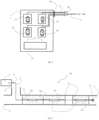
- the operating drum 1 It is the central supply and control unit for the spray chain.
- the actual control unit 15 controls the unwinding and winding units of 11, 12, 13 and 14 via the control lines 17 and unwinds and winds the connecting hoses and cables depending on the length required.
- the connecting hoses for disinfectant, electrical power, data cables and camera cables are combined in a coupling 8 and led out of the operating drum 1 via an outlet roller 16.
- the spray chain is coupled to the connecting hoses or connecting cables via the coupling 8. Disinfectant, etc. and electrical power are fed from outside into the corresponding connection points. at the unwinding and winding units 11, 12, 13 and 14.
- a pump is integrated in 12, which pumps the disinfectant into the connecting hose to 12 for subsequent atomization via a spray head 6.
- the supply lines and supply cables 9 are wound up on the unwinding and winding units 11, 12, 13 and 14 with a length of up to 500 m each and function in the same way as an electrically operated reel.
- the supply lines 9 are combined after the coupling 8 into a single - wrapped - supply line 2.
- the operating drum 1, as a complete unit, can be mounted on its own carrier, trailer or in a vehicle.
- the spray chain can be introduced and moved in various ways.
- a traction device can be introduced first and then the spray chain can be pulled.
- the spray chain can be pushed, or a vehicle can be attached to the head of the chain and pull the spray chain behind it.
- the operating drum serves as a control system for regulating the spray chain, the propulsion speed in the pipe and thus the residence time of the irradiation and the general process monitoring as well as process logging.
- a disinfectant is sprayed towards hard-to-reach places. This has a particularly bactericidal effect and can penetrate into remote corners in atomized or nebulized form.
- the spray mist is able to penetrate biofilms 20 and therefore also work in depth.
- This spraying process can be carried out independently of the other operation of the spray chain, preferably by the spray nozzles provided on the spray chain.
- the fluid with the agent can be supplied via a hose that is attached to the spray chain.
- Both the aqueous and gaseous disinfectants are preferably introduced into the pipe via pressure lines connected to the spray chain and sprayed as required using pumps and remote-controlled valves.
- the fluid can also be pumped from a storage tank that is moved along with the system.
- the spray chain 18 must be specially designed: It essentially consists of the supply line 2, the spray heads 6, the spacers 5 and connection adapters 10 and(or one or more radiation sources 4. It is pre-assembled depending on the required length, pre-inserted into the pipe 3, then coupled to the coupling 8 and then completely inserted into the pipe 3.
- the spray chain is therefore inserted into the pipe 3 with spacers 5 oriented almost radially to its "spine", the length of which is variable and depends on the diameter of the pipe - generally the fluid conductor -, the UVC radiation sources 4, the connection adapters 10 and spray heads 6.
- the spray chain is connected to the supply lines of the operating drum 1 by means of a coupling 8.
- the connection adapters 10 have an integrated cable passage and are beneficial for the stability of the spray chain in the longitudinal direction - the spacers 5 (at least three at the same or adjacent axial point are recommended) ensure the stability of the spray chain in the transverse direction.
- the duration of the fogging and/or the irradiation duration and intensity of the light lamps depends on the level of contamination in general, the strength/thickness of the biofilm and the pipe material, and according to internal investigations is on average 0.5-4 seconds or 0.1-10 watts/cm2. Longer irradiation times and higher intensities are of course also possible.
- the fog can be removed by fans on at least one side of the building to be cleaned or kept in motion (back and forth), on the one hand to quickly return to operating status after cleaning, and on the other hand to increase the effect through movement.
- the electric current for the lamps 4 and the disinfectant (in general: the agent) for spraying by means of the spray heads 6 are introduced into the pipe via the supply line 2.
- the operating drum 1 also represents the energy source for supplying the lamps 4 with electrical current.
- the operating drum 1 also supplies the Disinfectant is ensured.
- the disinfectant and the gas are fed into the pipe 3 via the supply line 2 by means of pumps.
- the disinfectant is atomized via the spray heads 6, which are activated individually by means of solenoid valves if necessary.
- the rough cleaning - pre-cleaning of the pipes etc. can be done either by flushing with water or by pigging, and if necessary another flush or pigging.
- the next step is disinfection using UVC light and/or the agent.
- the agent is pumped into the pipe 3 using a separate pressure line, which is integrated into the supply line 2, and sprayed locally using the spray heads 6. At the end, the pipe is rinsed with water.
- the diameter of the pipes into which a spray chain (adapted to the respective construction) can be inserted is at least 1 inch (25.4 mm) and max. DN 1500 mm; for non-circular cross-sections, analogous values apply, which the person skilled in the art can easily determine with knowledge of the invention.
- the spray nozzles 6 are preferably oriented one after the other in different circumferential directions in order to quickly and reliably achieve uniform misting of the interior and thus of the entire surface of the building (pipe) when the spray heads are positioned approximately centrally in the component/pipe.
- UVC radiation sources 4 can be varied depending on the application and depends on the degree of contamination, the necessary residence time (irradiation time) in the pipe 3, the intended working time and the like. If there is a significant deviation from the circular cross-section in buildings, an adjustment can be made without any problems if the geometry is known.
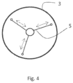
- the spray chain 18 has, as shown Fig.4 clearly visible, essentially radially projecting spacers 5, which ensure that the spray chain is always kept at a distance from the floor and the side walls, even when it is rotated about its longitudinal axis.
- the spacers 5 can, depending on the size of the diameter of the pipe 3, be provided with different lengths (for example, adjustable in length, in the Fig.4 indicated with " ⁇ ----->” or interchangeable).
- the spacers 5 usually consist of three arms offset from one another in the circumferential direction at different angles (preferably 120°), which preferably have rollers (only indicated, without reference number) mounted on the respective outer end of each arm, which allow easier movement in the pipe 3.
- Such arms are provided on the chain of the spray chain at a suitable axial distance as required.
- the spacers can also be arranged in the manner of a spiral, axially and offset in the circumferential direction; with knowledge of the invention and the respective field of application, it is easy for the person skilled in the art to make his choice here.
- connecting couplings at the front and rear so that the connecting adapter 10 can be coupled here.
- the connecting adapter 10 and the spacer 5 each have a free cross-section in the middle for the passage of the supply line 2.
- the UVC lamp is connected to the connection adapter 10 (with seal) and this provides the necessary rigidity to insert the spray chain 18 into the pipe 3 and to move it.
- the spray chain especially if it is designed to be constantly pulled, has a mobility in its "spine” that allows it to follow any curvatures of the pipe or structure. This can be achieved by means of ball joints or, more simply, by providing sufficient play in the connecting elements from chain link to chain link (spine).
- the spacers 5 can be provided with rollers or sliding shoes at their free ends to facilitate movement. They are preferably elastic at least in the "longitudinal direction" in order to overcome unevenness more easily through elastic deformation.
- the spray chain 18 can be provided with at least one hose for the disinfectant, with an outlet being provided at least at one point.
- an outlet being provided at least at one point.
- the provision of a camera with data transmission to the outside and, if necessary, a source of light in the visible wavelength range at this point/these points is advantageous for controlling the fluid release and for monitoring the success of the cleaning process.
- lower region of a hanger, reactor, filter, structure, or device or, more generally, of an object, means the lower half and in particular the lower quarter of the total height, "lowest region” means the lowest quarter and in particular an even smaller part; while “middle region” means the middle third of the total height (width - length). All these terms have their common meaning, applied to the intended position of the object in question.
- the terms "front”, “back”, “top”, “bottom” and so on are used in the common sense and with reference to the object in its usual position of use. This means that in a weapon the muzzle of the barrel is “front”, that the bolt or slide is moved “back” by the explosion gases, etc. In the case of the spray chain, the direction of movement refers to the movement during the cleaning process.
Landscapes
- Health & Medical Sciences (AREA)
- Life Sciences & Earth Sciences (AREA)
- General Health & Medical Sciences (AREA)
- Veterinary Medicine (AREA)
- Public Health (AREA)
- Animal Behavior & Ethology (AREA)
- Epidemiology (AREA)
- Engineering & Computer Science (AREA)
- Chemical & Material Sciences (AREA)
- Chemical Kinetics & Catalysis (AREA)
- General Chemical & Material Sciences (AREA)
- Mechanical Engineering (AREA)
- Pest Control & Pesticides (AREA)
- Zoology (AREA)
- Environmental Sciences (AREA)
- Plant Pathology (AREA)
- Wood Science & Technology (AREA)
- Dentistry (AREA)
- Agronomy & Crop Science (AREA)
- Optics & Photonics (AREA)
- Physics & Mathematics (AREA)
- Toxicology (AREA)
- Apparatus For Disinfection Or Sterilisation (AREA)
Description
Die Erfindung betrifft eine Vorrichtung zur Desinfektion von Innenwänden von Rohrleitungen, entsprechend dem Oberbegriff des Anspruches 1. Die im Folgenden offenbarte Desinfektion von Behältern oder Bauwerken dient lediglich der Darstellung der Erfindung, ist jedoch nicht Teil der beanspruchten Erfindung.The invention relates to a device for disinfecting the inner walls of pipelines, according to the preamble of claim 1. The disinfection of containers or structures disclosed below serves merely to illustrate the invention, but is not part of the claimed invention.
In (trink)wasserdurchflossenen Rohren, Behältern oder Bauwerken, gleich welchen Querschnittes, kommt es mit der Zeit zur Bildung von mehr oder weniger starken Biofilmen, die sich an der Innenrohrwand bilden und als Lebensgrundlage für Mikroorganismen dienen. Solange diese Biofilme frei von schädlichen Krankheitskeimen und Erregern sind, ist dies nicht weiter problematisch.In pipes, containers or structures through which (drinking) water flows, regardless of their cross-section, biofilms of varying thickness form over time. These biofilms form on the inner wall of the pipe and serve as a living environment for microorganisms. As long as these biofilms are free of harmful germs and pathogens, this is not a problem.
In diesen Biofilmen können sich jedoch auch pathogene Keime (Bakterien und/oder Viren wie z.B. Escherichia coli, Enterokokken, Legionellen oder Pseudomonas aeruginosa), aber auch Pilze und deren Sporen, bei Lichteinfall auch Algen, ansiedeln, die sich dort vermehren und mit dem durch das Rohr durchfließenden Wasser ausgespült werden. Diese Mikroorganismen können dann zu den einzelnen Verbrauchern (z.B. bei Trinkwasserversorgungssystemen zu den einzelnen Haushalten) gelangen und zu einer Gesundheitsgefährdung für Menschen und Tieren führen.However, pathogenic germs (bacteria and/or viruses such as Escherichia coli, enterococci, legionella or Pseudomonas aeruginosa), as well as fungi and their spores, and when exposed to light, algae, can also settle in these biofilms. These microorganisms can then multiply there and be flushed out with the water flowing through the pipe. These microorganisms can then reach the individual consumers (e.g. in the case of drinking water supply systems, to individual households) and pose a health risk to humans and animals.
Deshalb ist es notwendig, Trinkwasserversorgungssysteme bei Bedarf zu reinigen, zu beproben und gegebenenfalls auch zu desinfizieren.It is therefore necessary to clean, sample and, if necessary, disinfect drinking water supply systems.
Beim Desinfizieren versetzt man ein System in einen Zustand (Milieu), in dem Mikroorganismen abgetötet oder derart geschädigt werden, dass ein Wachstum oder eine Vermehrung nicht mehr zu erwarten ist. Weiters bedeutet Desinfektion auch bei Vorhandensein von Viren deren Inaktivierung. Dieser Zustand ist im Allgemeinen zeitlich begrenzt und muss gegebenenfalls immer wieder wiederholt werden.Disinfection involves putting a system into a state (environment) in which microorganisms are killed or damaged to such an extent that they are no longer expected to grow or multiply. Disinfection also means inactivating viruses if they are present. This state is generally limited in time and may need to be repeated again and again.
Die derzeit gängigen Verfahren der Desinfektion von (trink)wasserdurchflossenen Rohren, Behältern oder Bauwerken nach dem Stand der Technik beruhen auf dem Einsatz von wässerigen Desinfektionslösungen oder Gasen.The currently common state-of-the-art methods for disinfecting pipes, containers or structures through which (drinking) water flows are based on the use of aqueous disinfectant solutions or gases.
Dabei werden im Durchflussverfahren oder Standverfahren wässerige Desinfektionslösungen in die zu desinfizierenden Bauteile zu- bzw. ein bzw. durchgeleitet.In this process, aqueous disinfection solutions are fed into or passed through the components to be disinfected using the flow-through process or the stationary process.
Für Trinkwasserversorgungssysteme sind Maßnahmen nach den Vorgaben der ÖVWG RL W 55 oder DVGW W 291 anzuwenden, unter Einsatz der o.a. Desinfektionsmittel. Folgende Desinfektionstechniken werden derzeit eingesetzt (ohne Erläuterung der Vorreinigung und der Nachspülung) :
- Im Durchflussverfahren wird dem in einer Leitung fließenden Wasser ein Desinfektionsmittel i.R. meist Chlor oder Chlorlösung je nach Erfordernis in unterschiedlichen Konzentrationen und unterschiedlichen Zeiten zugesetzt.
- Beim Standverfahren lässt man die zur Desinfektion verwendete Desinfektionslösung (z.B. stärker gechlortes Wasser) für einen längeren Zeitraum (etwa 24 - 48 Stunden) in den Rohrleitungen stehen und leitet sie anschließend ab.
- In the flow-through process, a disinfectant, usually chlorine or chlorine solution, is added to the water flowing in a pipe in different concentrations and at different times as required.
- In the standing process, the disinfectant solution used for disinfection (e.g. highly chlorinated water) is left to stand in the pipes for a longer period of time (about 24 - 48 hours) and then drained away.
Der Nachteil der o.a. Techniken ist der, dass einerseits zu entsorgende Desinfektionslösungen in größeren Mengen anfallen und andererseits das z.B. gechlorte Wasser anschließend langwierig aus den Leitungen und Behältern entfernt werden muss.
Problematisch wird es trotz der erläuterten Desinfektion aber immer dann, wenn sich im Biofilm sehr resistente Keime, wie z.B. Pseudomonas aeruginosa, einnisten. Hat sich dieser Keim im Biofilm einmal manifestiert, ist mit einer chemischen Desinfektion - wie o.a.- keine Möglichkeit gegeben, diesen nachhaltig aus dem Rohr bzw. Biofilm zu entfernen. Bei Chloreinsatz schützt sich dieser nämlich mittels einer wachsähnlichen Schicht und "sitzt" sozusagen die Gefahrensituation aus.Despite the disinfection described above, it becomes problematic when very resistant germs, such as Pseudomonas aeruginosa, nest in the biofilm. Once this germ has manifested itself in the biofilm, there is no way of permanently removing it from the pipe or biofilm using chemical disinfection - as mentioned above. When chlorine is used, the biofilm protects itself with a wax-like layer and "sits out" the dangerous situation, so to speak.
Es ist Ziel und Aufgabe der Erfindung, eine Vorrichtung anzugeben, die in der Lage ist, auch mit derart resistenten Keimen fertig zu werden.It is the aim and object of the invention to provide a device which is able to cope with such resistant germs.
Erfindungsgemäß werden diese Ziele durch eine Vorrichtung erreicht, die die im kennzeichnenden Teil des Anspruches 1 angegebenen Merkmale aufweist. Mit anderen Worten, es wird durch die entleerte und gegebenenfalls vorgereinigte Rohrleitung, eine Sprühkette bewegt, die zumindest eine Düse zur Abgabe und Vernebelung des Desinfektionsmittels und/oder zumindest eine Quelle für UV Licht, insbesondere eine UVC-Quelle aufweist. Die Sprühkette ("Sprüh" wegen des Versprühens von Nebel und/oder elektromagnetischen Strahlen, letztere je brauchbarer, je "härter") ist, wie im Folgenden näher erläutert, so aufgebaut, dass die Düse und/oder Quelle Abstand vom Boden und den seitlichen Wänden des Rohres, aufweist.According to the invention, these objectives are achieved by a device having the features specified in the characterizing part of claim 1. In other words, a spray chain is moved through the emptied and possibly pre-cleaned pipeline, which has at least one nozzle for dispensing and nebulizing the disinfectant and/or at least one source of UV light, in particular a UVC source. The spray chain ("spray" because of the spraying of mist and/or electromagnetic rays, the latter the more useful, the "harder") is, as explained in more detail below, constructed in such a way that the nozzle and/or Source distance from the bottom and the side walls of the pipe.
Die erfindungsgemäße Vorrichtung weist eine Sprühkette auf, die in die vorgereinigte oder ungereinigte Rohrleitung, eingeführt und dort aktiviert wird, somit das Desinfektionsmittel in vernebelter Form abgibt und von einer sogenannten Betriebstrommel aus, gesteuert wird. Die Sprühkette kann von einem vorher in die Rohrleitung, eingeführten Zugmittel (Kette, Seil, etc.) gezogen werden, sie kann an ein (ferngelenktes) Fahrzeug angehängt werden, oder auf andere Weise durch den zu reinigenden Bereich bewegt werden.The device according to the invention has a spray chain that is introduced into the pre-cleaned or uncleaned pipeline and activated there, thus releasing the disinfectant in a nebulized form and is controlled by a so-called operating drum. The spray chain can be pulled by a traction device (chain, rope, etc.) previously introduced into the pipeline, it can be attached to a (remote-controlled) vehicle, or moved in another way through the area to be cleaned.
Mit Hilfe der Sprüh und Nebeldüsen kann erfindungsgemäß auch Alkohol in das Gebäude eingebracht werden, welcher den kompletten Biofilm vernichtet und die pathogenen Keime an ihrer Vermehrung und Ausbreitung hindert. Das Alkohol-Sprühen mit hohem Druck bringt auch eine mechanische Ablösung des Biofilms mit sich. Ein mechanisches Abscheren ist sozusagen mit inbegriffen.According to the invention, alcohol can also be introduced into the building using the spray and mist nozzles, which destroys the entire biofilm and prevents the pathogenic germs from multiplying and spreading. Spraying alcohol at high pressure also results in the biofilm being mechanically removed. Mechanical shearing is included, so to speak.
Das Vorsehen entsprechender Lichtquellen, ihre Energiezufuhr über Stromleitungen und die Aktivierung mittels Schaltern ist auch ohne weitere Erläuterung direkt verständlich, dass zumeist mehrere derartige Quellen vorgesehen sind, die in unterschiedliche Richtungen gerichtet sind, ist in Kenntnis der Erfindung wohl naheliegend.The provision of corresponding light sources, their energy supply via power lines and the activation by means of switches is immediately understandable even without further explanation; the fact that usually several such sources are provided, which are directed in different directions, is probably obvious given knowledge of the invention.
Eine UV Behandlung an sich ist bei der Desinfektion zur Trinkwasseraufbereitung als Stand der Technik zu bezeichnen. Doch wird dabei Trinkwasser im Durchlaufverfahren durch sogenannte UVC Desinfektionsanlagen geleitet und anschließend in das Trinkwassernetz eingespeist. Diese Anlagen können auch direkt in die Wasserleitungen selbst eingebaut werden oder es wird die UV-Anlage bei einer Wasserversorgung unmittelbar nach der Wassergewinnung und einer eventuellen Aufbereitung, auf jeden Fall aber vor dem Verteilernetz und eventuellen Speicherbehältern, eingebaut.UV treatment itself can be described as state of the art in the disinfection of drinking water. However, drinking water is passed through so-called UVC disinfection systems in a continuous process and then fed into the drinking water network. These systems can also be installed directly in the water pipes themselves or the UV system is installed in a water supply immediately after water extraction and any treatment, but in any case before the distribution network and any storage tanks.
Beim Stand der Technik kann mit dem Befüllen des Rohres mit sauberem Wasser nach der Reinigung und dem üblichen Nachspülen mit reinem Wasser, das aber noch nicht zur weiteren Verwendung gebracht, sondern abgelassen wird, kann sich der natürliche Biofilm mit seiner "normalen" Besiedelung im Laufe der Zeit wieder manifestieren.With the current state of the art, filling the pipe with clean water after cleaning and the usual rinsing with pure water, which is not yet used for further use, but is drained, the natural biofilm with its "normal" colonization can manifest itself again over time.
Durch den Einsatz der erfindungsgemäßen Technologie kann man alle oben angeführten Nachteile vermeiden und selbst Pseudomonas aeruginosa wirkungsvoll bekämpfen und so eine den gesetzlichen Anforderungen entsprechende, lang anhaltende Keimfreiheit in brauchwasserdurchflossenen wie auch lang anhaltende Trinkwassertauglichkeit in trinkwasserdurchflossenen Rohren, Behältern oder Bauwerken erzielen.By using the technology according to the invention, all of the disadvantages mentioned above can be avoided and even Pseudomonas aeruginosa can be effectively combated, thus achieving long-lasting sterility in pipes, containers or structures through which domestic water flows, in accordance with legal requirements, as well as long-lasting suitability for drinking water in pipes, containers or structures through which drinking water flows.
Es können erfindungsgemäß alle bekannten Desinfektionsmittel, flüssig oder gasförmig, verwendet werden, Beispiele sind:
Halogenhältige Chemikalien, wie Chlor, Chlorbleichlauge (Natriumhypochlorit-Lösung), Chlorkalk (Calciumhypochlorit), Chlordioxid; Sauerstoffhältige Chemikalien, wie Wasserstoffperoxid, Kaliumpermanganat, Ozon, Peressigsäure; Stickstoffhältige Chemikalien, wie quarternäre Ammoniumverbindungen, Benzalkoniumchlorid, Cetylalkoniumchlorid; Alkohole, wie Isopropanol.According to the invention, all known disinfectants, liquid or gaseous, can be used, examples are:
Halogen-containing chemicals such as chlorine, chlorine bleach (sodium hypochlorite solution), chlorinated lime (calcium hypochlorite), chlorine dioxide; oxygen-containing chemicals such as hydrogen peroxide, potassium permanganate, ozone, peracetic acid; nitrogen-containing chemicals such as quaternary ammonium compounds, benzalkonium chloride, cetylalkonium chloride; alcohols such as isopropanol.
Insbesondere Licht im Wellenlängenbereich zwischen 200 und 300 Nanometern (nm) mit einem ausgeprägten Maximum bei ca. 265 nm eignet sich für die Desinfektion von Trinkwasser. Die optimale Wellenlänge kann je nach Mikroorganismus leicht variieren und gegebenenfalls berücksichtigt werden. Ein Vorteil einer solchen UV-Desinfektion gegenüber herkömmlichen Verfahren (chemische Desinfektion) ist der Umstand, dass es Bakterien und Viren nicht möglich ist, Resistenzen gegen ultraviolette Strahlung aufzubauen; in Kombination ergibt sich eine unerwartete Verbesserung gegenüber der Einzelwirkung.Light in the wavelength range between 200 and 300 nanometers (nm) with a pronounced maximum at around 265 nm is particularly suitable for disinfecting drinking water. The optimal wavelength can vary slightly depending on the microorganism and may be taken into account if necessary. One advantage of such UV disinfection compared to conventional methods (chemical disinfection) is the fact that bacteria and viruses are unable to build up resistance to ultraviolet radiation; in combination, this results in an unexpected improvement compared to the individual effect.
Es ist bereits gelungen, Wasser mithilfe von ultravioletten Leuchtdioden (UV-LEDs) zu desinfizieren. Die Bestrahlung mit UV-Licht zerstört das Erbgut von Bakterien, Viren und Sporen (allgemein: Keimen) und verhindert dadurch die Vermehrung der Organismen. In Sonderfällen können vorteilhafterweise auch noch kurzwelligere Strahlen eingesetzt werden, auch wenn deren Abgabe besonderen Sicherheitsmaßnahmen unterliegen muss.It has already been possible to disinfect water using ultraviolet light-emitting diodes (UV LEDs). Irradiation with UV light destroys the genetic material of bacteria, viruses and spores (generally: germs) and thus prevents the organisms from multiplying. In special cases, even shorter-wave rays can be used to advantage, although their emission must be subject to special safety measures.
Es konnte festgestellt werden, dass es auch bei hartnäckigen Keimen aller Art, die an Wänden von wasserführenden Gebilden nisten, durch das erfindungsgemäße Verfahren, insbesondere in der Kombinationsvariante, problemlos möglich ist, die der Gesetzeslage entsprechende Hygiene einzuhalten.It was found that even in the case of stubborn germs of all kinds that nest on the walls of water-bearing structures, it is possible to easily maintain the hygiene requirements required by law using the method according to the invention, particularly in the combination variant.
Die Erfindung wird im Folgenden anhand der Zeichnung näher beschrieben, dabei zeigt, rein schematisch:
- die
Fig. 1 einen Rohrzusammenschluss mit Verunreinigungen, - die
Fig. 2 eine sogenannte Betriebstrommel, - die
Fig. 3 eine erfindungsgemäß einsetzbare Sprühkette in Seitenansicht und - die
Fig. 4 in axialer Ansicht
- the
Fig.1 a pipe union with impurities, - the
Fig.2 a so-called operating drum, - the
Fig.3 a spray chain usable according to the invention in side view and - the
Fig.4 in axial view
Bevorzugt wird bei der Anwendung des Verfahrens mittels einer sogenannten Betriebstrommel, wie sie in
Es können erfindungsgemäß UVC bzw. UV LED Lampen, wie sie in
Zur Betriebstrommel 1 ist auszuführen: Sie ist die zentrale Versorgungs- und Steuerungseinheit für die Sprühkette. Die eigentliche Steuerungseinheit 15 steuert die Ab- bzw. Aufrolleinheiten von 11, 12, 13 und 14 über die Steuerleitungen 17 und rollt die Verbindungsschläuche und -kabel je nach gebrauchter Länge ab bzw. auf. Die Verbindungsschläuche für Desinfektionsmittel, elektr. Strom, Datenkabel und Kamerakabel werden in einer Kupplung 8 zusammengefasst und über eine Auslassrolle 16 aus der Betriebstrommel 1 ausgeleitet. Über die Kupplung 8 wird die Sprühkette an die Verbindungsschläuche bzw. Verbindungskabel angekoppelt. Desinfektionsmittel, etc. und elektrischer Strom werden von extern in die entsprechenden Anschlussstellen bei den Ab- bzw. Aufrolleinheiten 11, 12, 13 und 14 eingespeist. In 12 integriert ist eine Pumpe, die das Desinfektionsmittel in den Verbindungsschlauch zu 12 hineinpumpt für die nachfolgende Zerstäubung über einen Sprühkopf 6.The following must be stated about the operating drum 1: It is the central supply and control unit for the spray chain. The
Die Versorgungsleitungen und Versorgungskabel 9 sind mit einer jeweiligen Länge von bis zu 500 m auf den Ab- bzw. Aufrolleinheiten 11, 12, 13 und 14 aufgerollt und funktionieren analog einer elektrisch betriebenen Haspel. Die Versorgungsleitungen 9 sind nach der Kupplung 8 in zu einer einzigen - umwickelten - Versorgungsleitung 2 zusammengefasst. Die Betriebstrommel 1, als gesamte Einheit, kann auf einem eigenen Träger, Anhänger oder in einem Kfz montiert werden.The supply lines and supply cables 9 are wound up on the unwinding and winding
Das Einbringen und das Bewegen der Sprühkette kann auf verschiedene Weise erfolgen, es kann ein Zugmittel zuerst eingebracht werden und dann die Sprühkette gezogen werden, es kann unter Umständen die Sprühkette geschoben werden, oder an ihrem Kopf ist ein Fahrzeug angebracht, das die Sprühkette hinter sich herzieht.The spray chain can be introduced and moved in various ways. A traction device can be introduced first and then the spray chain can be pulled. In some cases, the spray chain can be pushed, or a vehicle can be attached to the head of the chain and pull the spray chain behind it.
Die Betriebstrommel dient als Steuerungsanlage zur Regelung der Sprühkette, der Vortriebsgeschwindigkeit im Rohr und somit der Verweilzeit der Bestrahlung und der allgemeinen Prozessüberwachung sowie Prozessprotokollierung.The operating drum serves as a control system for regulating the spray chain, the propulsion speed in the pipe and thus the residence time of the irradiation and the general process monitoring as well as process logging.
In Rohrleitungsystemen 3 wird speziell in schwer zugänglichen Stellen ein Desinfektionsmittel in Richtung zu diesen Stellen gesprüht. Dieses wirkt besonders bakterizid und kann, in zerstäubter oder vernebelter Form, auch in entlegene Winkel, vordringen. Darüber hinaus ist der Sprühnebel in der Lage, in Biofilme 20 einzudringen und daher auch in der Tiefe zu wirken. Dieser Sprühvorgang kann unabhängig vom anderen Betrieb der Sprühkette, bevorzugt durch die Sprühdüsen, die an der Sprühkette vorgesehen sind, durchgeführt werden. Das Fluid mit dem Mittel kann über einen Schlauch zugeführt werden, der an der Sprühkette befestigt ist.In
Sowohl die wässerigen Desinfektionsmittel als auch die gasförmigen werden bevorzugt mittels Druckleitungen, die mit der Sprühkette verbunden sind, in das Rohr eingeführt und mittels Pumpen und ferngesteuerten Ventilen passend versprüht. In Sonderfällen kann das Fluid aber auch aus einem mitbewegten Vorratstank gepumpt werden.Both the aqueous and gaseous disinfectants are preferably introduced into the pipe via pressure lines connected to the spray chain and sprayed as required using pumps and remote-controlled valves. In special cases, the fluid can also be pumped from a storage tank that is moved along with the system.
Zur Sprühkette 18 ist speziell auszuführen: Sie besteht im Wesentlichen aus der Versorgungsleitung 2, den Sprühköpfen 6, den Abstandhaltern 5 und Verbindungsadaptern 10 und(oder einer oder mehreren Strahlenquellen 4. Sie wird je nach benötigter Länge vormontiert, in das Rohr 3 voreingeschoben, anschließend an der Kupplung 8 angekuppelt und dann vollständig ins Rohr 3 eingebracht.The
Die Sprühkette kann je nach Anwendungsfall entweder
- mechanisch eingeschoben
- mit dem Wasser im Rohr eingeschwemmt,
- mit Druckluft eingeblasen,
- mittels Seilzug oder Roboter ziehend geführt
- mechanically inserted
- washed in with the water in the pipe,
- blown in with compressed air,
- guided by a cable pull or robot pulling
Die Sprühkette wird also mit annähernd radial zu Ihrer "Wirbelsäule" orientierten Abstandhaltern 5, deren Länge variabel und abhängig vom Durchmesser des Rohres - allgemein des Fluidleiters - ist, den UVC Strahlenquellen 4, den Verbindungsadaptern 10 und Sprühköpfen 6 in das Rohr 3 eingeführt. Die Sprühkette wird mittels einer Kupplung 8 an die Versorgungsleitungen der Betriebstrommel 1 angeschlossen. Die Verbindungsadapter 10 haben einen integrierten Kabeldurchlass und sind für die Stabilität der Sprühkette in Längsrichtung günstig - die Abstandhalter 5 (zumindest drei jeweils an gleicher oder benachbarter axialer Stelle sind empfehlenswert) sorgen für die Stabilität der Sprühkette in Querrichtung.The spray chain is therefore inserted into the
Die Dauer des Einnebelns und/oder die Bestrahlungsdauer und Bestrahlungsintensität durch die Lichtlampen hängt von der Verschmutzung allgemein, von der Stärke/Dicke des Biofilms und des Rohrmaterials ab, und liegt nach internen Untersuchungen im Durchschnitt bei 0,5- 4 Sekunden bzw. 0,1-10 Watt/ cm2. Längere Bestrahlungszeiten und höhere Intensitäten sind natürlich auch möglich. Der Nebel kann am Ende der Behandlung oder auch während der Behandlung durch Ventilatoren an zumindest einer Seite des zu reinigenden Gebäudes abgezogen oder in Bewegung (hin-her) gehalten werden, einerseits um nach erfolgter Reinigung rasch in den Betriebszustand zurückzukommen, andererseits um die Wirkung durch die Bewegung zu erhöhen.The duration of the fogging and/or the irradiation duration and intensity of the light lamps depends on the level of contamination in general, the strength/thickness of the biofilm and the pipe material, and according to internal investigations is on average 0.5-4 seconds or 0.1-10 watts/cm2. Longer irradiation times and higher intensities are of course also possible. At the end of the treatment or during the treatment, the fog can be removed by fans on at least one side of the building to be cleaned or kept in motion (back and forth), on the one hand to quickly return to operating status after cleaning, and on the other hand to increase the effect through movement.
Über die Versorgungsleitung 2 werden der elektrische Strom für die Lampen 4, das Desinfektionsmittel (allgemein: das Mittel) für die Versprühung mittels der Sprühköpfe 6 in das Rohr eingeführt.The electric current for the lamps 4 and the disinfectant (in general: the agent) for spraying by means of the spray heads 6 are introduced into the pipe via the supply line 2.
Die Betriebstrommel 1 stellt auch die Energiequelle für die Versorgung der Lampen 4 mit elektr. Strom dar. Über die Betriebstrommel 1 wird auch die Versorgung mit Desinfektionsmittel sichergestellt. Das Desinfektionsmittel und das Gas werden mittels Pumpen über die Versorgungsleitung 2 in das Rohr 3 eingeleitet. Die Desinfektionsmittelzerstäubung wird über die Sprühköpfe 6 durchgeführt, die gegebenenfalls einzeln mittels Magnetventilen aktiviert werden.The operating drum 1 also represents the energy source for supplying the lamps 4 with electrical current. The operating drum 1 also supplies the Disinfectant is ensured. The disinfectant and the gas are fed into the
Die Grobreinigung - Vorreinigung der Rohre etc. kann entweder mittels Wasserspülungen oder durch Molchen erfolgen, und geg. nochmals eine Spülung oder Molchung. Im nächsten Schritt erfolgt dann die Desinfektion mittels UVC Licht und/oder dem Mittel. Das Mittel wird mittels eigener Druckleitung, die in der Versorgungsleitung 2 integriert ist, in das Rohr 3 hineingepumpt und dort lokal mittels der Sprühköpfe 6 versprüht. Am Ende erfolgt ein Ausspülen des Rohres mit Wasser.The rough cleaning - pre-cleaning of the pipes etc. can be done either by flushing with water or by pigging, and if necessary another flush or pigging. The next step is disinfection using UVC light and/or the agent. The agent is pumped into the
Der Durchmesser der Rohre, in welche eine (jeweils bautechnisch angepasste) Sprühkette eingeführt werden kann, beträgt mindestens 1 Zoll (25,4 mm) und max. DN 1500 mm; bei nichtkreisförmigem Querschnitt gelten analoge Werte, die der Fachmann in Kenntnis der Erfindung leicht feststellen kann.The diameter of the pipes into which a spray chain (adapted to the respective construction) can be inserted is at least 1 inch (25.4 mm) and max. DN 1500 mm; for non-circular cross-sections, analogous values apply, which the person skilled in the art can easily determine with knowledge of the invention.
Die Sprühdüsen 6 sind bevorzugt nacheinander in unterschiedliche Umfangsrichtung orientiert, um bei etwa mittiger Position der Sprühköpfe im Bauteil/Rohr rasch und zuverlässig eine gleichmäßige Einnebelung des Inneren und damit der gesamten Oberfläche des Gebäudes (Rohres) zu erreichen.The spray nozzles 6 are preferably oriented one after the other in different circumferential directions in order to quickly and reliably achieve uniform misting of the interior and thus of the entire surface of the building (pipe) when the spray heads are positioned approximately centrally in the component/pipe.
Zwischen den einzelnen Strahlern 4 befinden sich - je nach Rohrdurchmesser - unterschiedlich große Abstandhalter 5, die gewährleisten, dass die Strahler annähernd (+/- 10 %) mittig im Rohr 3 positioniert sind und so die UVC Strahlen gleichmäßig im Rohr 3 abgegeben werden. Die Anzahl der UVC Strahlenquellen 4 ist je nach Anwendungsfall variierbar und hängt vom Grad der Verkeimung, der notwendigen Verweilzeit (Bestrahlungszeit) im Rohr 3, der vorgesehenen Arbeitsdauer und Ähnlichem ab. Bei starkem Abweichen vom Kreisquerschnitt in Gebäuden kann in Kenntnis der Geometrie ohne Probleme eine Anpassung erfolgen.Between the individual radiators 4 there are spacers 5 of different sizes - depending on the pipe diameter - which ensure that the radiators are positioned approximately (+/- 10%) in the middle of the
Die Sprühkette 18 weist, wie aus
Die Abstandhalter 5 können, je nach Größe des Durchmessers des Rohres 3, mit unterschiedlichen Längen (beispielsweise längenverstellbar, in der
Die Abstandhalter 5 bestehen im Regelfall aus drei in Umfangsrichtung in unterschiedlichen Winkeln voneinander versetzten Armen (bevorzugt 120°), die bevorzugt am jeweiligen äußeren Ende jedes Arms Rollen (nur angedeutet, ohne Bezugszeichen) montiert haben, die ein leichteres Bewegen im Rohr 3 ermöglichen. Solche Arme werden je nach Bedarf in passendem axialen Abstand an der Kette der Sprühkette vorgesehen.The spacers 5 usually consist of three arms offset from one another in the circumferential direction at different angles (preferably 120°), which preferably have rollers (only indicated, without reference number) mounted on the respective outer end of each arm, which allow easier movement in the
Es können die Abstandhalter auch nach Art einer Wendel axial und in Umfangsrichtung versetzt angeordnet sein, in Kenntnis der Erfindung und des jeweiligen Anwendungsgebietes ist es für den Fachmann ein Leichtes, hier seine Wahl zu treffen.The spacers can also be arranged in the manner of a spiral, axially and offset in the circumferential direction; with knowledge of the invention and the respective field of application, it is easy for the person skilled in the art to make his choice here.
In der axialen Mitte der Abstandhalter 5 befinden sich vorne und hinten Verbindungskupplungen, sodass der Verbindungsadapter 10 hier angekoppelt werden kann. Verbindungsadapter 10 und Abstandhalter 5 haben jeweils mittig einen freien Querschnitt für den Durchgang der Versorgungsleitung 2.In the axial center of the spacers 5 there are connecting couplings at the front and rear so that the connecting
An die Verbindungsadapter 10 (mit Dichtung) wird die UVC Lampe angekoppelt und dadurch wird die benötigte Steifheit erhalten, die notwendig ist, die Sprühkette 18 ins Rohr 3 einzuführen und zu bewegen. Neben dieser Steifigkeit einerseits weist die Sprühkette, insbesondere, wenn sie so ausgelegt ist, dass sie stets gezogen wird, eine Beweglichkeit in ihrer "Wirbelsäule" auf, die es ihr ermöglicht, eventuellen Krümmungen des Rohres oder Bauwerks zu folgen. Dies kann durch Kugelgelenke oder, einfacher, durch ausreichend großes Spiel der Verbindungselemente von Kettenglied zu Kettenglied (Wirbel) erreicht werden.The UVC lamp is connected to the connection adapter 10 (with seal) and this provides the necessary rigidity to insert the
Die Abstandhalter 5 können, wie bereits erwähnt, an ihren freien Enden mit Rollen oder Gleitschuhen zur leichteren Bewegung versehen sein. Sie sind bevorzugt zumindest in "Längsrichtung" elastisch, um über Unebenheiten durch elastische Deformation leichter hinweg zu kommen.As already mentioned, the spacers 5 can be provided with rollers or sliding shoes at their free ends to facilitate movement. They are preferably elastic at least in the "longitudinal direction" in order to overcome unevenness more easily through elastic deformation.
Die Sprühkette 18 kann mit zumindest einem Schlauch für das Desinfektionsmittel versehen sein, wobei zumindest an einer Stelle ein Auslass vorgesehen ist. Bevorzugt sind es mehrere gezielt zu öffnende Auslässe, die in verschiedene Umfangsrichtungen weisen, um Fluid in verschiedene Richtungen sprühen zu können. Das Vorsehen einer Kamera mit Datenübertragung nach Außen und gegebenenfalls einer Quelle für Licht im sichtbaren Wellenbereich an dieser Stelle / diesen Stellen ist zur Steuerung der Fluidabgabe und zur Kontrolle des Erfolges des Reinigungsvorganges vorteilhaft.The
Es soll noch darauf hingewiesen werden, dass in der Beschreibung und den Ansprüchen Angaben wie "unterer Bereich" eines Gehänges, Reaktors, Filters, Bauwerks, oder einer Vorrichtung oder, ganz allgemein, eines Gegenstandes, die untere Hälfte und insbesondere das untere Viertel der Gesamthöhe bedeutet, "unterster Bereich" das unterste Viertel und insbesondere einen noch kleineren Teil; während "mittlerer Bereich" das mittlere Drittel der Gesamthöhe (Breite - Länge) meint. All diese Angaben haben ihre landläufige Bedeutung, angewandt auf die bestimmungsgemäße Position des betrachteten Gegenstandes.It should also be noted that in the description and the claims, terms such as "lower region" of a hanger, reactor, filter, structure, or device or, more generally, of an object, means the lower half and in particular the lower quarter of the total height, "lowest region" means the lowest quarter and in particular an even smaller part; while "middle region" means the middle third of the total height (width - length). All these terms have their common meaning, applied to the intended position of the object in question.
In der Beschreibung und den Ansprüchen werden die Begriffe "vorne", "hinten", "oben", "unten" und so weiter in der landläufigen Form und unter Bezugnahme auf den Gegenstand in seiner üblichen Gebrauchslage, gebraucht. Das heißt, dass bei einer Waffe die Mündung des Laufes "vorne" ist, dass der Verschluss bzw. Schlitten durch die Explosionsgase nach "hinten" bewegt wird, etc.. Bewegungsrichtung bezieht sich, bei der Sprühkette auf die Bewegung beim Reinigungsvorgang.In the description and claims, the terms "front", "back", "top", "bottom" and so on are used in the common sense and with reference to the object in its usual position of use. This means that in a weapon the muzzle of the barrel is "front", that the bolt or slide is moved "back" by the explosion gases, etc. In the case of the spray chain, the direction of movement refers to the movement during the cleaning process.
In der Beschreibung und den Ansprüchen bedeutet "im Wesentlichen" eine Abweichung von bis zu 10 % des angegebenen Wertes, wenn es physikalisch möglich ist, sowohl nach unten als auch nach oben, ansonsten nur in die sinnvolle Richtung, bei Gradangaben (Winkel und Temperatur) sind damit ± 10° gemeint.In the description and claims, "substantially" means a deviation of up to 10% of the stated value, if it is physically possible, both upwards and downwards, otherwise only in the reasonable direction, in the case of degrees (angle and temperature) this means ± 10°.
Alle Mengenangaben und Anteilsangaben, insbesondere solche zur Abgrenzung der Erfindung, soweit sie nicht die konkreten Beispiele betreffen, sind mit ± 10 % Toleranz zu verstehen, somit beispielsweise: 11 % bedeutet: von 9,9 % bis 12,1 %. Bei Bezeichnungen wie bei: "ein Lösungsmittel" ist das Wort "ein" nicht als Zahlwort, sondern als unbestimmter Artikel anzusehen, wenn nicht aus dem Zusammenhang etwas anderes hervorgeht.All quantities and proportions, particularly those used to define the invention, unless they relate to the specific examples, are to be understood with a tolerance of ± 10%, thus for example: 11% means: from 9.9% to 12.1%. In terms such as "a solvent", the word "a" is not to be regarded as a number but as an indefinite article, unless the context indicates otherwise.
Der Begriff: "Kombination" bzw. "Kombinationen" steht, soferne nichts anderes angegeben, für alle Arten von Kombinationen, ausgehend von zwei der betreffenden Bestandteile bis zu einer Vielzahl derartiger Bestandteile, der Begriff: "enthaltend" steht auch für "bestehend aus".The term "combination" or "combinations" means, unless otherwise stated, all types of combinations based on two of the relevant Components up to a multitude of such components, the term "containing" also stands for "consisting of".
- 11
- BetriebstrommelOperating drum
- 22
- Versorgungsleitungsupply line
- 33
- Rohr ( Fluidleiter )Pipe (fluid conductor)
- 44
- StrahlenquelleRadiation source
- 55
- AbstandhalterSpacers
- 66
- Sprühkopfspray nozzle
- 77
- DesinfektionsmittelsprühnebelDisinfectant spray
- 88th
- Kupplungcoupling
- 99
- Versorgungsleitungen aus der BetriebstrommelSupply lines from the operating drum
- 1010
- VerbindungsadapterConnection adapter
- 1111
- Ab- bzw. Aufrolleinheit für den Verbindungsschlauch für GasUnwinding or winding unit for the connecting hose for gas
- 1212
- Ab- bzw. Aufrolleinheit für den Verbindungsschlauch für DesinfektionsmittelUnwinding or winding unit for the connecting hose for disinfectant
- 1313
- Ab- bzw. Aufrolleinheit für den Verbindungsschlauch für das Kabel für die StromversorgungUnwinding or winding unit for the connecting hose for the power supply cable
- 1414
- Ab- bzw. Aufrolleinheit für den Verbindungsschlauch für das Kabel für die KameraUnwinding or winding unit for the connecting hose for the cable for the camera
- 1515
- SteuerungseinheitControl unit
- 1616
- AuslassrolleOutlet roller
- 1717
- SteuerleitungenControl cables
- 1818
- Sprühkette insgesamtSpray chain total
- 1919
- VerbindungsadapterConnection adapter
- 2020
- BiofilmBiofilm
Claims (8)
- A device designed to be suitable for disinfecting inner walls of pipelines (3) using disinfectants and UV light, wherein said device has at least one spray head (6) for the disinfectant and one source (4) for UV light, characterized in that the at least one spray head (6) and the one source (4) are arranged on a spray chain (18), and wherein spacers (5) are provided which are formed such that the spray chain (18) is retained spaced apart from lateral wall regions of the pipeline inner wall.
- The device according to Claim 1, characterized in that the spacers (5) have two end regions and engage with the spray chain (18) with the one end region and are provided with sliding blocks or rollers on the other, free end region.
- The device according to Claim 1 or 2, characterized in that the spacers (5) are adjustable in length.
- The device according to any one of Claims 1 to 3, characterized in that at least three spacers (5) are provided which are oriented in different circumferential directions.
- The device according to any one of Claims 1 to 4, characterized in that the disinfectant is selected from the group consisting of: chemicals which contain a halogen and/or oxygen and/or nitrogen, and/or alcohols.
- The device according to any one of the preceding claims, characterized in that UVC or UV LED lamps are used as the source (4).
- The device according to Claim 6, characterized in that light in the wavelength range of between 200 and 300 nanometers (nm) is used.
- Use of a device according to any one of the preceding claims for disinfecting pipelines.
Applications Claiming Priority (3)
| Application Number | Priority Date | Filing Date | Title |
|---|---|---|---|
| ATA50240/2018A AT520717B1 (en) | 2018-03-22 | 2018-03-22 | Disinfection of pipelines |
| ATA51116/2018A AT521129A1 (en) | 2018-03-22 | 2018-12-13 | Device for the disinfection of pipelines, containers and structures |
| PCT/AT2019/060082 WO2019178624A1 (en) | 2018-03-22 | 2019-03-13 | Device for disinfecting pipelines, containers and structures |
Publications (3)
| Publication Number | Publication Date |
|---|---|
| EP3768331A1 EP3768331A1 (en) | 2021-01-27 |
| EP3768331C0 EP3768331C0 (en) | 2024-07-17 |
| EP3768331B1 true EP3768331B1 (en) | 2024-07-17 |
Family
ID=65991475
Family Applications (1)
| Application Number | Title | Priority Date | Filing Date |
|---|---|---|---|
| EP19714303.5A Active EP3768331B1 (en) | 2018-03-22 | 2019-03-13 | Device and its use for disinfecting pipelines |
Country Status (4)
| Country | Link |
|---|---|
| US (1) | US20200405895A1 (en) |
| EP (1) | EP3768331B1 (en) |
| CA (1) | CA3093010C (en) |
| WO (1) | WO2019178624A1 (en) |
Families Citing this family (6)
| Publication number | Priority date | Publication date | Assignee | Title |
|---|---|---|---|---|
| US11723993B2 (en) * | 2020-02-20 | 2023-08-15 | Soulnano Limited | Ultraviolet disinfection apparatus |
| US20210259451A1 (en) * | 2020-02-20 | 2021-08-26 | Soulnano Limited | Food and beverage processor comprising ultraviolet disinfection apparatus |
| CN111547833B (en) * | 2020-05-12 | 2021-03-19 | 上海市政工程设计研究总院(集团)有限公司 | Self-generating disinfection robot for pressure pipeline |
| CN111547809B (en) * | 2020-05-12 | 2021-05-11 | 上海市政工程设计研究总院(集团)有限公司 | A degassing unit for pipeline under pressure ventilation well |
| DE102021121861B4 (en) | 2021-08-24 | 2025-02-20 | Laser Zentrum Hannover E.V. | Device for killing organisms in water with light and its use |
| CN118579927B (en) * | 2024-08-02 | 2024-09-27 | 东海县石榴街道农村经济和农业技术服务中心 | Drinking water disinfection device for livestock breeding |
Citations (1)
| Publication number | Priority date | Publication date | Assignee | Title |
|---|---|---|---|---|
| US5072487A (en) * | 1989-08-04 | 1991-12-17 | J. F. Walton & Co., Inc. | Duct cleaning apparatus |
Family Cites Families (5)
| Publication number | Priority date | Publication date | Assignee | Title |
|---|---|---|---|---|
| US6054097A (en) * | 1998-08-03 | 2000-04-25 | Innovatech | Expanding plasma emission source microorganism inactivation system |
| WO2011153288A1 (en) * | 2010-06-01 | 2011-12-08 | Alexander Farren | Uv sterilization of containers |
| US8473097B2 (en) * | 2010-12-15 | 2013-06-25 | S & S X-Ray Products, Inc | Pass-through wall-mounted medications cabinet with UV sterilization |
| US11142470B2 (en) * | 2013-07-15 | 2021-10-12 | American Water Works Company, Inc. | Disinfection of water mains using ultraviolet light and oxidizing agents |
| CN104740670A (en) * | 2015-04-08 | 2015-07-01 | 芜湖锐进医疗设备有限公司 | Medical apparatus workshop disinfecting device |
-
2019
- 2019-03-13 EP EP19714303.5A patent/EP3768331B1/en active Active
- 2019-03-13 CA CA3093010A patent/CA3093010C/en active Active
- 2019-03-13 US US16/976,555 patent/US20200405895A1/en active Pending
- 2019-03-13 WO PCT/AT2019/060082 patent/WO2019178624A1/en not_active Ceased
Patent Citations (1)
| Publication number | Priority date | Publication date | Assignee | Title |
|---|---|---|---|---|
| US5072487A (en) * | 1989-08-04 | 1991-12-17 | J. F. Walton & Co., Inc. | Duct cleaning apparatus |
Also Published As
| Publication number | Publication date |
|---|---|
| WO2019178624A1 (en) | 2019-09-26 |
| US20200405895A1 (en) | 2020-12-31 |
| CA3093010C (en) | 2022-12-13 |
| EP3768331C0 (en) | 2024-07-17 |
| CA3093010A1 (en) | 2019-09-26 |
| EP3768331A1 (en) | 2021-01-27 |
Similar Documents
| Publication | Publication Date | Title |
|---|---|---|
| EP3768331B1 (en) | Device and its use for disinfecting pipelines | |
| WO2019136504A1 (en) | Cleaning apparatus | |
| EP3294961B1 (en) | Improved self-disinfecting drain trap having a coating | |
| EP2165978A1 (en) | Assembly and method for chemical and physical preparation of water with UV radiation | |
| DE102007055449A1 (en) | Tap connection useful in table water dispenser, fresh juice dispenser, water cooler, tap or showering head, comprises a liquid outlet, UV-radiation source, and a membrane filter arranged in an outlet end or in a mounting plate | |
| DE102014017033A1 (en) | Stationary fluid exchange station for rail vehicles | |
| DE102018129811A1 (en) | Disinfection device and compressor system, connection device and treatment device with such | |
| DE102017102871A1 (en) | Endoscope, method for cleaning an endoscope, and cleaning device for cleaning an endoscope | |
| AT520717B1 (en) | Disinfection of pipelines | |
| EP3350380A1 (en) | Self-disinfecting drain trap assembly and method for operating same | |
| DE10248561A1 (en) | Milking device and method for disinfecting milking components | |
| EP1340718B1 (en) | Apparatus for sterilizing water by UV-radiation and by means of a quartz tube comprising a purifying plug | |
| WO2020254643A1 (en) | Disinfection and/or cleaning system, and method for disinfecting and/or cleaning a shower system | |
| DE202011000504U1 (en) | Device for providing sterilized ice for making beverages | |
| DE202018104239U1 (en) | Device for cleaning and disinfecting wheels | |
| EP3988723A1 (en) | Safety device | |
| CH717137A2 (en) | Disinfection device and method for disinfecting liquids. | |
| DE202008017943U1 (en) | Ozone generator for chemical disinfection of water | |
| EP2114830B1 (en) | Sanitary disinfection apparatus for the control of microorganisms in water, sanitation device | |
| DE202011050404U1 (en) | cleaner | |
| EP2536441B1 (en) | Medical device, concentrate and method for treating water | |
| DE102008031592A1 (en) | Method for thermo-chemical sterilization of sterile tanks and other production surfaces in food industry, involves spraying one or multiple sterilizing agents via high pressure pumps in saturated vapor flow in turbulence reactor | |
| DE102009019854A1 (en) | Aerosol generator | |
| DE102021132823A1 (en) | Device and method for cleaning a container filling system | |
| EP3156708B1 (en) | Tubing assembly |
Legal Events
| Date | Code | Title | Description |
|---|---|---|---|
| STAA | Information on the status of an ep patent application or granted ep patent |
Free format text: STATUS: UNKNOWN |
|
| STAA | Information on the status of an ep patent application or granted ep patent |
Free format text: STATUS: THE INTERNATIONAL PUBLICATION HAS BEEN MADE |
|
| TPAC | Observations filed by third parties |
Free format text: ORIGINAL CODE: EPIDOSNTIPA |
|
| PUAI | Public reference made under article 153(3) epc to a published international application that has entered the european phase |
Free format text: ORIGINAL CODE: 0009012 |
|
| STAA | Information on the status of an ep patent application or granted ep patent |
Free format text: STATUS: REQUEST FOR EXAMINATION WAS MADE |
|
| 17P | Request for examination filed |
Effective date: 20200812 |
|
| AK | Designated contracting states |
Kind code of ref document: A1 Designated state(s): AL AT BE BG CH CY CZ DE DK EE ES FI FR GB GR HR HU IE IS IT LI LT LU LV MC MK MT NL NO PL PT RO RS SE SI SK SM TR |
|
| AX | Request for extension of the european patent |
Extension state: BA ME |
|
| DAV | Request for validation of the european patent (deleted) | ||
| DAX | Request for extension of the european patent (deleted) | ||
| STAA | Information on the status of an ep patent application or granted ep patent |
Free format text: STATUS: EXAMINATION IS IN PROGRESS |
|
| 17Q | First examination report despatched |
Effective date: 20211220 |
|
| RAP1 | Party data changed (applicant data changed or rights of an application transferred) |
Owner name: LESSTEC AG |
|
| RIN1 | Information on inventor provided before grant (corrected) |
Inventor name: MOCK, MANFRED |
|
| P01 | Opt-out of the competence of the unified patent court (upc) registered |
Effective date: 20230525 |
|
| GRAP | Despatch of communication of intention to grant a patent |
Free format text: ORIGINAL CODE: EPIDOSNIGR1 |
|
| STAA | Information on the status of an ep patent application or granted ep patent |
Free format text: STATUS: GRANT OF PATENT IS INTENDED |
|
| INTG | Intention to grant announced |
Effective date: 20240301 |
|
| GRAS | Grant fee paid |
Free format text: ORIGINAL CODE: EPIDOSNIGR3 |
|
| GRAA | (expected) grant |
Free format text: ORIGINAL CODE: 0009210 |
|
| STAA | Information on the status of an ep patent application or granted ep patent |
Free format text: STATUS: THE PATENT HAS BEEN GRANTED |
|
| AK | Designated contracting states |
Kind code of ref document: B1 Designated state(s): AL AT BE BG CH CY CZ DE DK EE ES FI FR GB GR HR HU IE IS IT LI LT LU LV MC MK MT NL NO PL PT RO RS SE SI SK SM TR |
|
| REG | Reference to a national code |
Ref country code: CH Ref legal event code: EP |
|
| REG | Reference to a national code |
Ref country code: DE Ref legal event code: R096 Ref document number: 502019011697 Country of ref document: DE |
|
| REG | Reference to a national code |
Ref country code: IE Ref legal event code: FG4D Free format text: LANGUAGE OF EP DOCUMENT: GERMAN |
|
| U01 | Request for unitary effect filed |
Effective date: 20240813 |
|
| U07 | Unitary effect registered |
Designated state(s): AT BE BG DE DK EE FI FR IT LT LU LV MT NL PT SE SI Effective date: 20240826 |
|
| P04 | Withdrawal of opt-out of the competence of the unified patent court (upc) registered |
Free format text: CASE NUMBER: APP_48238/2024 Effective date: 20240821 |
|
| P05 | Withdrawal of opt-out of the competence of the unified patent court (upc) changed |
Free format text: CASE NUMBER: APP_48238/2024 Effective date: 20240826 |
|
| PG25 | Lapsed in a contracting state [announced via postgrant information from national office to epo] |
Ref country code: PL Free format text: LAPSE BECAUSE OF FAILURE TO SUBMIT A TRANSLATION OF THE DESCRIPTION OR TO PAY THE FEE WITHIN THE PRESCRIBED TIME-LIMIT Effective date: 20240717 Ref country code: GR Free format text: LAPSE BECAUSE OF FAILURE TO SUBMIT A TRANSLATION OF THE DESCRIPTION OR TO PAY THE FEE WITHIN THE PRESCRIBED TIME-LIMIT Effective date: 20241018 |
|
| PG25 | Lapsed in a contracting state [announced via postgrant information from national office to epo] |
Ref country code: IS Free format text: LAPSE BECAUSE OF FAILURE TO SUBMIT A TRANSLATION OF THE DESCRIPTION OR TO PAY THE FEE WITHIN THE PRESCRIBED TIME-LIMIT Effective date: 20241117 |
|
| PG25 | Lapsed in a contracting state [announced via postgrant information from national office to epo] |
Ref country code: HR Free format text: LAPSE BECAUSE OF FAILURE TO SUBMIT A TRANSLATION OF THE DESCRIPTION OR TO PAY THE FEE WITHIN THE PRESCRIBED TIME-LIMIT Effective date: 20240717 |
|
| PG25 | Lapsed in a contracting state [announced via postgrant information from national office to epo] |
Ref country code: ES Free format text: LAPSE BECAUSE OF FAILURE TO SUBMIT A TRANSLATION OF THE DESCRIPTION OR TO PAY THE FEE WITHIN THE PRESCRIBED TIME-LIMIT Effective date: 20240717 Ref country code: RS Free format text: LAPSE BECAUSE OF FAILURE TO SUBMIT A TRANSLATION OF THE DESCRIPTION OR TO PAY THE FEE WITHIN THE PRESCRIBED TIME-LIMIT Effective date: 20241017 |
|
| PG25 | Lapsed in a contracting state [announced via postgrant information from national office to epo] |
Ref country code: RS Free format text: LAPSE BECAUSE OF FAILURE TO SUBMIT A TRANSLATION OF THE DESCRIPTION OR TO PAY THE FEE WITHIN THE PRESCRIBED TIME-LIMIT Effective date: 20241017 Ref country code: PL Free format text: LAPSE BECAUSE OF FAILURE TO SUBMIT A TRANSLATION OF THE DESCRIPTION OR TO PAY THE FEE WITHIN THE PRESCRIBED TIME-LIMIT Effective date: 20240717 Ref country code: IS Free format text: LAPSE BECAUSE OF FAILURE TO SUBMIT A TRANSLATION OF THE DESCRIPTION OR TO PAY THE FEE WITHIN THE PRESCRIBED TIME-LIMIT Effective date: 20241117 Ref country code: HR Free format text: LAPSE BECAUSE OF FAILURE TO SUBMIT A TRANSLATION OF THE DESCRIPTION OR TO PAY THE FEE WITHIN THE PRESCRIBED TIME-LIMIT Effective date: 20240717 Ref country code: GR Free format text: LAPSE BECAUSE OF FAILURE TO SUBMIT A TRANSLATION OF THE DESCRIPTION OR TO PAY THE FEE WITHIN THE PRESCRIBED TIME-LIMIT Effective date: 20241018 Ref country code: ES Free format text: LAPSE BECAUSE OF FAILURE TO SUBMIT A TRANSLATION OF THE DESCRIPTION OR TO PAY THE FEE WITHIN THE PRESCRIBED TIME-LIMIT Effective date: 20240717 |
|
| U20 | Renewal fee for the european patent with unitary effect paid |
Year of fee payment: 7 Effective date: 20250220 |
|
| PG25 | Lapsed in a contracting state [announced via postgrant information from national office to epo] |
Ref country code: SM Free format text: LAPSE BECAUSE OF FAILURE TO SUBMIT A TRANSLATION OF THE DESCRIPTION OR TO PAY THE FEE WITHIN THE PRESCRIBED TIME-LIMIT Effective date: 20240717 |
|
| PGFP | Annual fee paid to national office [announced via postgrant information from national office to epo] |
Ref country code: NO Payment date: 20250320 Year of fee payment: 7 |
|
| PG25 | Lapsed in a contracting state [announced via postgrant information from national office to epo] |
Ref country code: CZ Free format text: LAPSE BECAUSE OF FAILURE TO SUBMIT A TRANSLATION OF THE DESCRIPTION OR TO PAY THE FEE WITHIN THE PRESCRIBED TIME-LIMIT Effective date: 20240717 |
|
| PG25 | Lapsed in a contracting state [announced via postgrant information from national office to epo] |
Ref country code: SK Free format text: LAPSE BECAUSE OF FAILURE TO SUBMIT A TRANSLATION OF THE DESCRIPTION OR TO PAY THE FEE WITHIN THE PRESCRIBED TIME-LIMIT Effective date: 20240717 |
|
| PGFP | Annual fee paid to national office [announced via postgrant information from national office to epo] |
Ref country code: GB Payment date: 20250324 Year of fee payment: 7 |
|
| PLBE | No opposition filed within time limit |
Free format text: ORIGINAL CODE: 0009261 |
|
| STAA | Information on the status of an ep patent application or granted ep patent |
Free format text: STATUS: NO OPPOSITION FILED WITHIN TIME LIMIT |
|
| 26N | No opposition filed |
Effective date: 20250422 |
|
| PGFP | Annual fee paid to national office [announced via postgrant information from national office to epo] |
Ref country code: CH Payment date: 20250401 Year of fee payment: 7 |
|
| PG25 | Lapsed in a contracting state [announced via postgrant information from national office to epo] |
Ref country code: MC Free format text: LAPSE BECAUSE OF FAILURE TO SUBMIT A TRANSLATION OF THE DESCRIPTION OR TO PAY THE FEE WITHIN THE PRESCRIBED TIME-LIMIT Effective date: 20240717 |
|
| PG25 | Lapsed in a contracting state [announced via postgrant information from national office to epo] |
Ref country code: IE Free format text: LAPSE BECAUSE OF NON-PAYMENT OF DUE FEES Effective date: 20250313 |