EP3768060B1 - Agricultural tillage implement, mainly rolling basket - Google Patents
Agricultural tillage implement, mainly rolling basket Download PDFInfo
- Publication number
- EP3768060B1 EP3768060B1 EP19721006.5A EP19721006A EP3768060B1 EP 3768060 B1 EP3768060 B1 EP 3768060B1 EP 19721006 A EP19721006 A EP 19721006A EP 3768060 B1 EP3768060 B1 EP 3768060B1
- Authority
- EP
- European Patent Office
- Prior art keywords
- basket
- rolling
- inner space
- rolling basket
- scraper
- Prior art date
- Legal status (The legal status is an assumption and is not a legal conclusion. Google has not performed a legal analysis and makes no representation as to the accuracy of the status listed.)
- Active
Links
- 238000005096 rolling process Methods 0.000 title claims description 71
- 238000003971 tillage Methods 0.000 title claims description 16
- 239000004575 stone Substances 0.000 claims description 6
- 239000002023 wood Substances 0.000 claims description 5
- 238000002360 preparation method Methods 0.000 claims description 4
- 238000006073 displacement reaction Methods 0.000 claims description 3
- 239000002689 soil Substances 0.000 description 12
- 238000004140 cleaning Methods 0.000 description 4
- 239000007787 solid Substances 0.000 description 3
- 239000011449 brick Substances 0.000 description 2
- 238000003780 insertion Methods 0.000 description 2
- 230000037431 insertion Effects 0.000 description 2
- 235000006760 Acer pensylvanicum Nutrition 0.000 description 1
- 241000219312 Chenopodium Species 0.000 description 1
- 241000196324 Embryophyta Species 0.000 description 1
- 210000000078 claw Anatomy 0.000 description 1
- 230000000694 effects Effects 0.000 description 1
- 238000004519 manufacturing process Methods 0.000 description 1
- 238000003466 welding Methods 0.000 description 1
Images

Classifications
-
- A—HUMAN NECESSITIES
- A01—AGRICULTURE; FORESTRY; ANIMAL HUSBANDRY; HUNTING; TRAPPING; FISHING
- A01B—SOIL WORKING IN AGRICULTURE OR FORESTRY; PARTS, DETAILS, OR ACCESSORIES OF AGRICULTURAL MACHINES OR IMPLEMENTS, IN GENERAL
- A01B29/00—Rollers
-
- A—HUMAN NECESSITIES
- A01—AGRICULTURE; FORESTRY; ANIMAL HUSBANDRY; HUNTING; TRAPPING; FISHING
- A01B—SOIL WORKING IN AGRICULTURE OR FORESTRY; PARTS, DETAILS, OR ACCESSORIES OF AGRICULTURAL MACHINES OR IMPLEMENTS, IN GENERAL
- A01B21/00—Harrows with rotary non-driven tools
-
- A—HUMAN NECESSITIES
- A01—AGRICULTURE; FORESTRY; ANIMAL HUSBANDRY; HUNTING; TRAPPING; FISHING
- A01B—SOIL WORKING IN AGRICULTURE OR FORESTRY; PARTS, DETAILS, OR ACCESSORIES OF AGRICULTURAL MACHINES OR IMPLEMENTS, IN GENERAL
- A01B27/00—Clod-crushers
-
- A—HUMAN NECESSITIES
- A01—AGRICULTURE; FORESTRY; ANIMAL HUSBANDRY; HUNTING; TRAPPING; FISHING
- A01B—SOIL WORKING IN AGRICULTURE OR FORESTRY; PARTS, DETAILS, OR ACCESSORIES OF AGRICULTURAL MACHINES OR IMPLEMENTS, IN GENERAL
- A01B27/00—Clod-crushers
- A01B27/005—Clod-crushers comprising roller-type tools moving on the ground
-
- A—HUMAN NECESSITIES
- A01—AGRICULTURE; FORESTRY; ANIMAL HUSBANDRY; HUNTING; TRAPPING; FISHING
- A01B—SOIL WORKING IN AGRICULTURE OR FORESTRY; PARTS, DETAILS, OR ACCESSORIES OF AGRICULTURAL MACHINES OR IMPLEMENTS, IN GENERAL
- A01B29/00—Rollers
- A01B29/04—Rollers with non-smooth surface formed of rotatably-mounted rings or discs or with projections or ribs on the roller body; Land packers
- A01B29/048—Bar cage rollers
-
- A—HUMAN NECESSITIES
- A01—AGRICULTURE; FORESTRY; ANIMAL HUSBANDRY; HUNTING; TRAPPING; FISHING
- A01B—SOIL WORKING IN AGRICULTURE OR FORESTRY; PARTS, DETAILS, OR ACCESSORIES OF AGRICULTURAL MACHINES OR IMPLEMENTS, IN GENERAL
- A01B29/00—Rollers
- A01B29/06—Rollers with special additional arrangements
-
- A—HUMAN NECESSITIES
- A01—AGRICULTURE; FORESTRY; ANIMAL HUSBANDRY; HUNTING; TRAPPING; FISHING
- A01B—SOIL WORKING IN AGRICULTURE OR FORESTRY; PARTS, DETAILS, OR ACCESSORIES OF AGRICULTURAL MACHINES OR IMPLEMENTS, IN GENERAL
- A01B49/00—Combined machines
- A01B49/02—Combined machines with two or more soil-working tools of different kind
- A01B49/027—Combined machines with two or more soil-working tools of different kind with a rotating, soil working support element, e.g. a roller
-
- A—HUMAN NECESSITIES
- A01—AGRICULTURE; FORESTRY; ANIMAL HUSBANDRY; HUNTING; TRAPPING; FISHING
- A01B—SOIL WORKING IN AGRICULTURE OR FORESTRY; PARTS, DETAILS, OR ACCESSORIES OF AGRICULTURAL MACHINES OR IMPLEMENTS, IN GENERAL
- A01B15/00—Elements, tools, or details of ploughs
- A01B15/16—Discs; Scrapers for cleaning discs; Sharpening attachments
-
- A—HUMAN NECESSITIES
- A01—AGRICULTURE; FORESTRY; ANIMAL HUSBANDRY; HUNTING; TRAPPING; FISHING
- A01B—SOIL WORKING IN AGRICULTURE OR FORESTRY; PARTS, DETAILS, OR ACCESSORIES OF AGRICULTURAL MACHINES OR IMPLEMENTS, IN GENERAL
- A01B23/00—Elements, tools, or details of harrows
- A01B23/06—Discs; Scrapers for cleaning discs; Sharpening attachments; Lubrication of bearings
-
- A—HUMAN NECESSITIES
- A01—AGRICULTURE; FORESTRY; ANIMAL HUSBANDRY; HUNTING; TRAPPING; FISHING
- A01B—SOIL WORKING IN AGRICULTURE OR FORESTRY; PARTS, DETAILS, OR ACCESSORIES OF AGRICULTURAL MACHINES OR IMPLEMENTS, IN GENERAL
- A01B29/00—Rollers
- A01B29/04—Rollers with non-smooth surface formed of rotatably-mounted rings or discs or with projections or ribs on the roller body; Land packers
- A01B29/046—Rollers with non-smooth surface formed of rotatably-mounted rings or discs or with projections or ribs on the roller body; Land packers the soil-pressing body being a helical coil
Definitions
- This disclosure generally relates to an agricultural tillage implement, especially to a rolling basket with blades for crumbling soil, that is, for breaking up clods of soil, and which is mainly a tillage machine for tillage works after plowing and/or seedbed preparation.
- This rolling basket has a plurality of blades disposed generally evenly spaced around a circumference de-lined by a fixed radius away from the major axis thereby forming a basket structure.
- the basket structure defines an inner chamber of the rolling basket.
- the basket structure has a plurality of openings connecting the inner chamber to the outside of the basket structure.
- the blades extend axially from one end of the rolling basket to an opposing end.
- the rolling basket is connected to two support arms via bearings.
- the bearings are connected to the rolling basket at the ends.
- the bearings are configured to allow the rolling basket to rotate around its major axis.
- the support arm has a post configured to connect to the bearing.
- the bearing is configured to rotate around the post.
- the support ari--n also has a post configured to connect to the bearing, wherein the bearing is configured to rotate around that post.
- An internal scraper is provided to prevent the mud from pushing into the inner chamber of the rolling basket.
- the internal scraper is arranged in the longitudinal direction, extending radially in the inside of the basket and it is rigidly fixed.
- the internal scraper includes a stationary blade connected to two sleeves at each end of the stationary blade.
- the first sleeve receives the post.
- a pin can be inserted into matching openings to lock the first sleeve stationary with respect to the post.
- This internal scraper operates by removing the horns adhered to the blades and extending into the interior of the rolling basket from the swiveling blades during the rotation of the basket.
- the blades which have relative speed to the ground, e.g. twice the travel speed of the implement connected to the tractor - through the gaps between the blades, the detached claws are removed from the inside of the rolling basket.
- a further problem is that, due to the excessive distance between the internal scraper and the blade cooperating with it, the blade cannot eject the ground or other solid object penetrated into the interior of the rolling basket, and thus the rotation of the basket is stopped and its operation is impossible any more. In this case, the operator must remove the jammed clod, stone or piece of wood from the rolling basket which results in tiring manual work and significant downtime.
- the internal scraper must be arranged relatively far from the blades to reduce the possibility of insertion (clogging) of solid objects.
- the clogging of solid objects and the softer ground cannot be eliminated, in practice, in such a way, that enables continuous operation of the agricultural tillage implement.
- Our further aim is to improve the self-cleaning ability of the rolling basket.
- Another advantageous effect is that in the case of soft soil, inside the rolling basket, a thin walled soil "tubing" is formed which is pushed into the interior of the basket by rolling down the basket on the ground, from which the centrifugal force is pulled out through the openings into the free space outside the rolling basket.
- the present invention is an agricultural tillage implement, mainly rolling basket for tillage works after plowing and/or seedbed preparation.
- This rolling basket comprises a basket structure including a plurality of coaxial discs associated with longitudinal crushing blades extending from one end to an opposing end along a major axis of the basket structure.
- the crushing blades define an inner space of the basket structure, and said inner space being accessible through openings provided between the crushing blades.
- the basket structure is configured in such a way to rotate around the major axis.
- the rolling basket comprises a stationary internal scraper arranged in the inner chamber of the basket structure at a distance from the crushing blades.
- the essence of the invention lies in that the stationary internal scraper arranged in the inner space of the basket structure of the rolling basket in cooperation with one of the crushing blades so that the radial distance between the radially inner edge of the blades and the radially outer edge of the scraper has been significantly reduced, preferably at most to 2.5 cm.
- the stationary internal scraper arranged in the inner space of the basket structure of the rolling basket in cooperation with one of the crushing blades so that the radial distance between the radially inner edge of the blades and the radially outer edge of the scraper has been significantly reduced, preferably at most to 2.5 cm.
- at least one end, but preferably both ends of the stationary internal scraper is/are connected to stationary shaft pin(s) of the rotary basket via an elastic member.
- the elastic member is formed as a flexible, mainly C-shaped spring allowing flexible rotation and/or radial displacement of the internal scraper in the inner space of the rolling basket, when jamming a larger clump or a piece of stone or wood between the scraper and the cooperating blade.
- a support beam for the rolling basket is provided that can be hinged and upwardly displaceable to the frame of a tillage implement, in particular to a hinged or towed structure. It comprises bearing legs fixed to the ends of the support beam. Each bearing leg is provided with one of the shaft pins extending into the inner space of the basket structure of the rolling basket, so these coaxial shaft pins form a rotational centre line (major axis) for free rotation of the rolling basket.
- the invention relates to a crushing rolling basket, in particular for plowing and/or seedbed production, having coaxial discs and associated longitudinal blades, which together form a "basket structure", which is freely rotatable about the shaft pins.
- a stationary internal scraper is provided in connection (cooperation) with the rotating blades.
- the improvement according to the present invention lies, in that, in the inner space of the rolling basket, the internal scraper is arranged in such a way, that the scraper cooperates with one of the blades at significantly reduced radial distance between the radially inner edge of the blades and the radially outer edge of the scraper, preferably this distance should be max. 2.5 cm.
- at least one of the ends of the internal scraper is/are connected to the stationary shaft pin(s) of the rotary basket by means of a flexible element.
- an agricultural tillage implement e.g. for seedbed preparation works
- a tractor not shown
- the travel direction of the implement 1 is indicated by an arrow 2.
- the implement 1 has a frame V, provided with cultivating units, for example, looking in the direction of the arrow 2, in the front row, with goose foot hoes 3, behind which with rotary hoes 4 arranged in the next two rows, and the row behind them is equipped with levellers 5.
- levellers 5 In the last row of the frame V there are three pieces of rolling baskets 6 according to the invention arranged coaxially in this case.
- the rolling baskets 6 are hingedly connected to the frame V of the implement 1 by means of brackets 7.
- Figures 1 and 2 show that the rolling baskets 6 according to the invention are pivotally rotatable arranged about pins 8 through the brackets 7, so that the rolling baskets 6 are arranged to be displaced in the vertical direction indicated by arrow 10 against springs 9 ( Fig. 2 ).
- the spring 9 sits on a lower spring plate 25 and its upper end is connected to an articulated spring arm 25A ( Fig. 2 ).
- Fig. 1 shows that the frame V of the implement 1 is equipped with wheels 11, which can be hydraulically tilted to the working position around pins 12, i.e. they can be lifted.
- the wheels 11 of the implement 1 is thus in elevated position, i.e. in the air, in the working state, in which case the entire implement 1 is in fact supported vertically on the rolling baskets 6.
- These rolling baskets 6 work on a soil surface 13 to be cultivated by rolling down thereon in the direction of an arrow 14, to perform soil crushing and compacting work ( Fig. 1 ).
- Fig. 2 shows in more detail an exemplary embodiment of the rolling basket 6 according to the invention.
- the rolling basket 6 has a longitudinal support beam 15, with double-sided bearing legs 16 attached thereto.
- the support beam 15 is coupled to the frame V with hinged brackets 7 and the springs 9.
- each rolling basket 6 consists of double-sided end discs 17, intermediate discs 18 and longitudinal crushing blades 19 spaced apart from each other along the circumference of the discs 17 and 18.
- the blades 19 define an inner space 20 of the rolling bracket 6 from the outside, and this inner space 20 can communicate with the outer air space through openings 21 formed between the blades 19.
- Each rolling basket 6 comprises a basket structure 6A including the plurality of coaxial discs 17 and 18 associated with the longitudinal crushing blades 19 extending from one end to an opposing end along a major axis (rotational centre line) 24 of the basket structure 6A of the rolling basket 6.
- the crushing blades 19 define an inner space 20 of the basket structure 6A of the rolling basket 6, and said inner space 20 being accessible through openings 21 provided between the crushing blades 19.
- bearing housings 22 are secured to the two end discs 17 of the rolling basket 6.
- bearing housings 22 known bearings (not shown) are arranged.
- a shaft pin 23 is embedded, extending into the inner space 20 of the rolling basket 6.
- the two shaft pins 23 are coaxially arranged and secured to the bearing legs 16, preferably by welding.
- the bearing housings 22 of the two shaft pins 23 are fastened to the end discs 17 of the rolling basket 6 by screws.
- the rolling basket 6 is freely rotatable about the coaxial shaft pins 23 and the rotatational centre line 24.
- At least one of the shaft pin 23 of the rolling basket 6, fixed to the bearing leg 16 is provided with an elastic member 26, preferably an inverted C-shaped spring.
- the radially inner end of the elastic member 26 is fixed to the end of the shaft pin 23 by means of a screw 27.
- the radially outer end of the elastic element 26 is attached to the end of an internal scraper 29 e.g. by a screw 28 ( FIG. 4 ), which scraper 29 is arranged in a longitudinal direction and radially between the two end discs 17 in the inner space 20 of the rolling basket 6,
- a distance (spacing) T between the radially outer edge of the internal scraper 29 and the radially inner edge of the working crushing blade 19 is intentionally chosen to be relatively small, preferably up to 2.5 cm. Due to the reduced size of the distance T, the arrangement according to the invention cannot produce larger nuggets, according to our field experiments, and as a consequence, the self-cleaning feature of the proposed rolling basket 6 has been highly improved.
- the crushing blades 19 are arranged slightly oblique at the circumference of the rolling basket 6, in this case, at a small angle E along the circumference.
- the angle E can be, preferably between 5 and 10 degrees.
- the automatic and improved internal self-cleaning of the rolling baskets 6 is accomplished ( Fig, 1 ) being driven in the direction of travel indicated by the arrow 1 by means of a forced connection of the rolling baskets 6 with the soil surface 13. ( Fig. 4 ), As a result, the crushing blades 19 of the rotating basket 6 rotate in the direction of the arrow 14, passing the internal scraper 29 at a distance T, and then a piece of soil 31 (which is indicated with a thin line in FIG. 4 ) will be forced to move outwardly from the inner space 20 of the rolling basket 6 through the openings 21 between the crushing blades 19, i.e. it is ejected (shown by arrow 32 in FIG. 4 ).
Landscapes
- Life Sciences & Earth Sciences (AREA)
- Engineering & Computer Science (AREA)
- Mechanical Engineering (AREA)
- Soil Sciences (AREA)
- Environmental Sciences (AREA)
- Soil Working Implements (AREA)
Description
- This disclosure generally relates to an agricultural tillage implement, especially to a rolling basket with blades for crumbling soil, that is, for breaking up clods of soil, and which is mainly a tillage machine for tillage works after plowing and/or seedbed preparation.
- Such a solution is known, for example from
FR2586887A US-9,326,439 - The rolling basket is connected to two support arms via bearings. The bearings are connected to the rolling basket at the ends. The bearings are configured to allow the rolling basket to rotate around its major axis. The support arm has a post configured to connect to the bearing. The bearing is configured to rotate around the post. The support ari--n also has a post configured to connect to the bearing, wherein the bearing is configured to rotate around that post. Thus, the rolling basket, which is connected to the bearings, rotates around the posts.
- An internal scraper is provided to prevent the mud from pushing into the inner chamber of the rolling basket. The internal scraper is arranged in the longitudinal direction, extending radially in the inside of the basket and it is rigidly fixed. The internal scraper includes a stationary blade connected to two sleeves at each end of the stationary blade. The first sleeve receives the post. A pin can be inserted into matching openings to lock the first sleeve stationary with respect to the post.
- This internal scraper operates by removing the horns adhered to the blades and extending into the interior of the rolling basket from the swiveling blades during the rotation of the basket. The blades, which have relative speed to the ground, e.g. twice the travel speed of the implement connected to the tractor - through the gaps between the blades, the detached claws are removed from the inside of the rolling basket.
- The fundamental shortcoming of the above solution is - according to our practical experiences - that the internal scraper is too far away from the blades (approx. 8-10 cm), so that on the one hand too large nuggets can be formed, and on the other hand, due to the rigid connection between the blades and the internal scraper, stones, pieces of wood, plant remains, etc. they can get caught in the gap between the internal scraper and the blades, causing a forced stop of the rolling basket and the inability to work.
- A further problem is that, due to the excessive distance between the internal scraper and the blade cooperating with it, the blade cannot eject the ground or other solid object penetrated into the interior of the rolling basket, and thus the rotation of the basket is stopped and its operation is impossible any more. In this case, the operator must remove the jammed clod, stone or piece of wood from the rolling basket which results in tiring manual work and significant downtime.
- In the above solution, the internal scraper must be arranged relatively far from the blades to reduce the possibility of insertion (clogging) of solid objects. However, due to the rigid connection of the blades in the rolling basket, the clogging of solid objects and the softer ground cannot be eliminated, in practice, in such a way, that enables continuous operation of the agricultural tillage implement.
- It is a main object of the present invention to overcome the above-mentioned disadvantages, i.e. to provide an improved agricultural tillage implement, mainly rotating basket with more efficient and higher operational safety for plowing and seedbed tasks.
- Our further aim is to improve the self-cleaning ability of the rolling basket.
- The object of the present invention is solved by the invention as defined in the enclosed claims.
- According to the present invention, these problems are eliminated by the proposed measures, these are, on the one hand, the internal scraper is placed radially much closer to the blades, i.e., the spacing between them has been significantly reduced according to the invention. On the other hand, an elastic connection is provided at least one end or both ends of the internal scraper. According to the present invention elastic elements, preferably C-springs, provide a flexible connection for the internal scraper. As a result, nail, stone, brick, wood, etc. cannot get caught between the internal scraper and the blade, so that no blockage due to insertion can occur, and much smaller nuggets are created, than in the known solution.
- Another advantageous effect is that in the case of soft soil, inside the rolling basket, a thin walled soil "tubing" is formed which is pushed into the interior of the basket by rolling down the basket on the ground, from which the centrifugal force is pulled out through the openings into the free space outside the rolling basket.
- So the present invention is an agricultural tillage implement, mainly rolling basket for tillage works after plowing and/or seedbed preparation. This rolling basket comprises a basket structure including a plurality of coaxial discs associated with longitudinal crushing blades extending from one end to an opposing end along a major axis of the basket structure. The crushing blades define an inner space of the basket structure, and said inner space being accessible through openings provided between the crushing blades. The basket structure is configured in such a way to rotate around the major axis. Furthermore, the rolling basket comprises a stationary internal scraper arranged in the inner chamber of the basket structure at a distance from the crushing blades.
- The essence of the invention lies in that the stationary internal scraper arranged in the inner space of the basket structure of the rolling basket in cooperation with one of the crushing blades so that the radial distance between the radially inner edge of the blades and the radially outer edge of the scraper has been significantly reduced, preferably at most to 2.5 cm. On the other hand, in the inner space of the basket structure of the rolling basket, at least one end, but preferably both ends of the stationary internal scraper is/are connected to stationary shaft pin(s) of the rotary basket via an elastic member.
- The elastic member is formed as a flexible, mainly C-shaped spring allowing flexible rotation and/or radial displacement of the internal scraper in the inner space of the rolling basket, when jamming a larger clump or a piece of stone or wood between the scraper and the cooperating blade.
- In a preferred embodiment, a support beam for the rolling basket is provided that can be hinged and upwardly displaceable to the frame of a tillage implement, in particular to a hinged or towed structure. It comprises bearing legs fixed to the ends of the support beam. Each bearing leg is provided with one of the shaft pins extending into the inner space of the basket structure of the rolling basket, so these coaxial shaft pins form a rotational centre line (major axis) for free rotation of the rolling basket.
- Thus, the invention relates to a crushing rolling basket, in particular for plowing and/or seedbed production, having coaxial discs and associated longitudinal blades, which together form a "basket structure", which is freely rotatable about the shaft pins. In the interior of the basket structure, a stationary internal scraper is provided in connection (cooperation) with the rotating blades. The improvement according to the present invention lies, in that, in the inner space of the rolling basket, the internal scraper is arranged in such a way, that the scraper cooperates with one of the blades at significantly reduced radial distance between the radially inner edge of the blades and the radially outer edge of the scraper, preferably this distance should be max. 2.5 cm. Furthermore, in the interior of the rolling basket, at least one of the ends of the internal scraper is/are connected to the stationary shaft pin(s) of the rotary basket by means of a flexible element.
- The invention will be described in more detail with reference to the accompanying drawings, in which an exemplary embodiment of the present invention is shown. In the drawing:
-
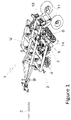
FIG. 1 illustrates a perspective view of an embodiment of an agricultural tillage machine equipped with rolling baskets according to the invention; -
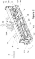
FIG. 2 illustrates a separate perspective view of the rolling basket ofFig. 1 ; -
FIG. 3 illustrates a longitudinal cross-sectional view of the end portion of the rolling basket ofFigure 2 , on a relatively larger scale; -
FIG. 4 is a cross-sectional view taken along line IV-IV inFigure 3 . - According to
Fig. 1 , an agricultural tillage implement 1, e.g. for seedbed preparation works, can be connected, e.g. to a tractor (not shown). The travel direction of the implement 1 is indicated by anarrow 2. The implement 1 has a frame V, provided with cultivating units, for example, looking in the direction of thearrow 2, in the front row, withgoose foot hoes 3, behind which with rotary hoes 4 arranged in the next two rows, and the row behind them is equipped with levellers 5. In the last row of the frame V there are three pieces ofrolling baskets 6 according to the invention arranged coaxially in this case. - The rolling
baskets 6 are hingedly connected to the frame V of the implement 1 by means ofbrackets 7.Figures 1 and2 show that the rollingbaskets 6 according to the invention are pivotally rotatable arranged aboutpins 8 through thebrackets 7, so that the rollingbaskets 6 are arranged to be displaced in the vertical direction indicated byarrow 10 against springs 9 (Fig. 2 ). The spring 9 sits on alower spring plate 25 and its upper end is connected to an articulatedspring arm 25A (Fig. 2 ). -
Fig. 1 shows that the frame V of the implement 1 is equipped withwheels 11, which can be hydraulically tilted to the working position around pins 12, i.e. they can be lifted. Thewheels 11 of the implement 1 is thus in elevated position, i.e. in the air, in the working state, in which case the entire implement 1 is in fact supported vertically on the rollingbaskets 6. These rollingbaskets 6 work on asoil surface 13 to be cultivated by rolling down thereon in the direction of anarrow 14, to perform soil crushing and compacting work (Fig. 1 ). -
Fig. 2 shows in more detail an exemplary embodiment of the rollingbasket 6 according to the invention. As indicated herein, the rollingbasket 6 has alongitudinal support beam 15, with double-sided bearing legs 16 attached thereto. Thesupport beam 15 is coupled to the frame V with hingedbrackets 7 and the springs 9. In fact, each rollingbasket 6 consists of double-sided end discs 17,intermediate discs 18 and longitudinal crushingblades 19 spaced apart from each other along the circumference of thediscs blades 19 define aninner space 20 of the rollingbracket 6 from the outside, and thisinner space 20 can communicate with the outer air space throughopenings 21 formed between theblades 19. - Each rolling
basket 6 comprises abasket structure 6A including the plurality ofcoaxial discs blades 19 extending from one end to an opposing end along a major axis (rotational centre line) 24 of thebasket structure 6A of the rollingbasket 6. The crushingblades 19 define aninner space 20 of thebasket structure 6A of the rollingbasket 6, and saidinner space 20 being accessible throughopenings 21 provided between the crushingblades 19. - It is more evident on the basis of
Figures 3 and 4 , those bearinghousings 22 are secured to the twoend discs 17 of the rollingbasket 6. In these bearinghousings 22 known bearings (not shown) are arranged. In each bearing, ashaft pin 23 is embedded, extending into theinner space 20 of the rollingbasket 6. The twoshaft pins 23 are coaxially arranged and secured to the bearinglegs 16, preferably by welding. Thus, the two shaft pins 23 on both sides of the bearinglegs 16 extend axially into theinner space 20 of the rollingbasket 6 to form therotational centre line 24 for the rollingbasket 6. In the present case, the bearinghousings 22 of the twoshaft pins 23 are fastened to theend discs 17 of the rollingbasket 6 by screws. Thus, the rollingbasket 6 is freely rotatable about the coaxial shaft pins 23 and therotatational centre line 24. - According to the invention, at least one of the
shaft pin 23 of the rollingbasket 6, fixed to thebearing leg 16 is provided with anelastic member 26, preferably an inverted C-shaped spring. The radially inner end of theelastic member 26 is fixed to the end of theshaft pin 23 by means of ascrew 27. The radially outer end of theelastic element 26 is attached to the end of aninternal scraper 29 e.g. by a screw 28 (FIG. 4 ), which scraper 29 is arranged in a longitudinal direction and radially between the twoend discs 17 in theinner space 20 of the rollingbasket 6, - It should be emphasized that according to the invention, a distance (spacing) T between the radially outer edge of the
internal scraper 29 and the radially inner edge of the working crushingblade 19 is intentionally chosen to be relatively small, preferably up to 2.5 cm. Due to the reduced size of the distance T, the arrangement according to the invention cannot produce larger nuggets, according to our field experiments, and as a consequence, the self-cleaning feature of the proposed rollingbasket 6 has been highly improved. - As shown in
FIG. 2 , the crushingblades 19 are arranged slightly oblique at the circumference of the rollingbasket 6, in this case, at a small angle E along the circumference. The angle E can be, preferably between 5 and 10 degrees. - During operation, the automatic and improved internal self-cleaning of the rolling
baskets 6 according to the present invention is accomplished (Fig, 1 ) being driven in the direction of travel indicated by the arrow 1 by means of a forced connection of the rollingbaskets 6 with thesoil surface 13. (Fig. 4 ), As a result, the crushingblades 19 of therotating basket 6 rotate in the direction of thearrow 14, passing theinternal scraper 29 at a distance T, and then a piece of soil 31 (which is indicated with a thin line inFIG. 4 ) will be forced to move outwardly from theinner space 20 of the rollingbasket 6 through theopenings 21 between the crushingblades 19, i.e. it is ejected (shown byarrow 32 inFIG. 4 ). - Even if a larger soil piece, brick, stone, or any other hard object enters between the crushing
blades 19 and/or between the crushingblade 19 and theinternal scraper 29, a jam may not occur because the flexibleelastic member 26 allows theinternal scraper 29 to rotate flexibly or to perform a flexible displacement towards the inside of therotating basket 6. The safety, economy and self-cleaning capability of therotating basket 6 have been surprisingly improved with these measures of the invention. -
- 1
- - Agricultural tillage implement
- 2
- - Arrow
- 3
- -Goose foot hoe
- 4
- - Rotary hoe cultivating unit
- 5
- - Leveller
- 6
- - Rotating basket
- 6A
- -Basket structure
- 7
- - Bracket
- 8
- - Pin
- 9
- - Spring
- 10
- - Arrow
- 11
- - Wheel
- 12
- - Pin
- 13
- - Soil surface (to be cultivated)
- 14
- - Arrow
- 15
- - Support beam
- 16
- - Bearing leg
- 17
- - End disc
- 18
- - Intermediate disc
- 19
- - Crushing blade
- 20
- - Inner space
- 21
- - Opening
- 22
- - Bearing housing
- 23
- - Shaft pin
- 24
- - Rotational centre line (major axis)
- 25
- - Lower spring plate
- 25A
- - Spring arm
- 26
- - Elastic member
- 27
- - Screw
- 28
- - Screw
- 29
- - Internal scraper
- 30
- - Arrow
- 31
- - Piece of soil
- 32
- - Arrow
- V
- - Frame
- E
- - Angle
Claims (2)
- An agricultural tillage implement with a rolling basket for tillage works after plowing and/or seedbed preparation, said rolling basket comprising a basket structure including a plurality of coaxial discs associated longitudinal crushing blades extending from one end to an opposing end along a major axis of the basket structure, wherein the crushing blades define an inner space of the basket structure, and said inner space being accessible through openings provided between the crushing blades, and the basket structure configured to rotate around a major axis, and comprising a stationary internal scraper arranged in the inner space of the basket structure at a distance from the crushing blades, characterized in that the a stationary internal scraper (29) arranged in the inner space (20) of the basket structure (6A) of the rolling basket (6) radially and in cooperation with the radial crushing blades (19) so that the radial distance (T) between the radially inner edge of the blade(s) (19) and the radially outer edge of the scraper (29) is reduced, at most to 2.5 cm, and that in the inner space (20) of the basket structure (6A) of the rolling basket (6), at least one end, mainly both ends of the stationary internal scraper (29) is/are connected to stationary shaft pin(s) (23) of the rotary basket (6) via an elastic member (26), wherein the elastic member (26) is formed as a flexible, mainly C-shaped spring allowing flexible rotation and/or radial displacement of the internal scraper (29) in the inner space (20) of the rolling basket (6), when jamming a larger clump or a piece of stone or wood between the scraper (29) and the cooperating blade (19).
- The agricultural tillage implement according to Claim 1, characterized in that a support beam (15) for the rolling basket (6) is provided that can be hinged and upwardly displaceable to the frame (V) of a tillage implement (1), in particular to a hinged or towed structure, and that comprising bearing legs (16) fixed to the ends of the support beam (15), and each bearing leg (16) is provided with one of the shaft pins (23) extending into the inner space (20) of the basket structure (6A) of the rolling basket (6), these coaxial shaft pins (23) form a rotational center line (24) for free rotation of the rolling basket (6).
Applications Claiming Priority (2)
| Application Number | Priority Date | Filing Date | Title |
|---|---|---|---|
| HU1800101A HU231127B1 (en) | 2018-03-23 | 2018-03-23 | Crushing roller covered with laths |
| PCT/HU2019/050011 WO2019180472A1 (en) | 2018-03-23 | 2019-03-18 | Agricultural tillage implement, mainly rolling basket |
Publications (2)
| Publication Number | Publication Date |
|---|---|
| EP3768060A1 EP3768060A1 (en) | 2021-01-27 |
| EP3768060B1 true EP3768060B1 (en) | 2022-08-10 |
Family
ID=89992654
Family Applications (1)
| Application Number | Title | Priority Date | Filing Date |
|---|---|---|---|
| EP19721006.5A Active EP3768060B1 (en) | 2018-03-23 | 2019-03-18 | Agricultural tillage implement, mainly rolling basket |
Country Status (7)
| Country | Link |
|---|---|
| EP (1) | EP3768060B1 (en) |
| HU (1) | HU231127B1 (en) |
| MD (1) | MD4837C1 (en) |
| PL (1) | PL3768060T3 (en) |
| RU (1) | RU2759601C1 (en) |
| UA (1) | UA123938C2 (en) |
| WO (1) | WO2019180472A1 (en) |
Families Citing this family (3)
| Publication number | Priority date | Publication date | Assignee | Title |
|---|---|---|---|---|
| CN111837469A (en) * | 2020-07-28 | 2020-10-30 | 范文红 | Jolt-squeeze device |
| RU210706U1 (en) * | 2022-01-13 | 2022-04-28 | Федеральное государственное бюджетное образовательное учреждение высшего образования "Ульяновский государственный аграрный университет имени П.А. Столыпина" | ROLLER |
| CN114402718B (en) * | 2022-02-14 | 2023-08-08 | 湖北三华生态农业科技发展有限公司 | Soil breaker for farming |
Family Cites Families (8)
| Publication number | Priority date | Publication date | Assignee | Title |
|---|---|---|---|---|
| SU603354A1 (en) * | 1976-08-20 | 1978-04-25 | Всесоюзный Ордена Трудового Красного Знамени Научно-Исследовательский Институт Механизации Сельского Хозяйства | Roller |
| DE7812988U1 (en) * | 1978-04-28 | 1978-09-28 | Howard Machinery Ltd., Bury St. Edmunds, Suffolk (Grossbritannien) | Crumb packer |
| FR2586887A1 (en) * | 1985-09-11 | 1987-03-13 | Lely France | Roller with bars for working the ground |
| SU1371532A1 (en) * | 1986-05-27 | 1988-02-07 | Научно-производственное объединение по механизации и электрификации сельского хозяйства "Целинсельхозмеханизация" | Counter-erosion roller |
| AT407817B (en) * | 1999-06-22 | 2001-06-25 | Vogel & Noot Landmasch | SOIL TILLING DEVICE |
| RU2206967C2 (en) * | 2000-11-21 | 2003-06-27 | Курский государственный технический университет | General-purpose rotary combined unit |
| US9326439B2 (en) * | 2013-01-31 | 2016-05-03 | Summers Manufacturing Company, Inc. | Agricultural implement with a scraper internal to a rolling basket |
| RU2014124371A (en) * | 2013-08-21 | 2015-12-27 | СиЭнЭйч ИНДАСТРИАЛ АМЕРИКА ЭлЭлСи | SOIL PROCESSING MACHINE WITH SCRAPER / DEFLECTOR |
-
2018
- 2018-03-23 HU HU1800101A patent/HU231127B1/en unknown
-
2019
- 2019-03-18 EP EP19721006.5A patent/EP3768060B1/en active Active
- 2019-03-18 MD MDA20200065A patent/MD4837C1/en active IP Right Grant
- 2019-03-18 WO PCT/HU2019/050011 patent/WO2019180472A1/en active Application Filing
- 2019-03-18 RU RU2020131858A patent/RU2759601C1/en active
- 2019-03-18 PL PL19721006.5T patent/PL3768060T3/en unknown
- 2019-03-18 UA UAA202005788A patent/UA123938C2/en unknown
Also Published As
| Publication number | Publication date |
|---|---|
| MD20200065A2 (en) | 2021-01-31 |
| EP3768060A1 (en) | 2021-01-27 |
| UA123938C2 (en) | 2021-06-23 |
| RU2759601C1 (en) | 2021-11-16 |
| PL3768060T3 (en) | 2023-02-13 |
| MD4837C1 (en) | 2023-07-31 |
| HU231127B1 (en) | 2020-12-28 |
| WO2019180472A1 (en) | 2019-09-26 |
| MD4837B1 (en) | 2022-12-31 |
| HUP1800101A2 (en) | 2019-09-30 |
Similar Documents
| Publication | Publication Date | Title |
|---|---|---|
| EP3768060B1 (en) | Agricultural tillage implement, mainly rolling basket | |
| CA2841682C (en) | Agricultural implement with a scraper internal to a rolling basket | |
| EP2661168B1 (en) | Agricultural machine | |
| KR102273479B1 (en) | Cultivator with harrow | |
| US4987959A (en) | Farm machine for working the soil | |
| EP2418928B1 (en) | Weeder with rotating members having hook-like elements. | |
| US7628346B1 (en) | Poultry litter rejuvenating machine | |
| NL192071C (en) | Soil cultivation machine. | |
| EP2401899B1 (en) | Agricultural implement | |
| EP0255751B1 (en) | A soil cultivating machine | |
| RU2538821C1 (en) | Rotary subsoil cultivator | |
| US2785613A (en) | Apparatus for soil preparation | |
| RU2297125C1 (en) | Tillage machine and unit for attachment of tine to spherical disk | |
| NL8602301A (en) | SOIL PROCESSING UNIT WITH EQUALIZATION SECTION POSTED. | |
| EP0189957B1 (en) | Soil cultivating machine | |
| JP6327811B2 (en) | Agricultural machine | |
| CN215601794U (en) | Traction type disc harrow | |
| KR200475597Y1 (en) | Plow apparatus for excavator | |
| US417421A (en) | Combined cultivator and harrow | |
| SU1440368A1 (en) | Soil-tilling working member | |
| US3375879A (en) | Soil pulverizing unit | |
| EP3569048A1 (en) | Flail mower with protection device | |
| SU344806A1 (en) | COMBINED SOIL PROCESSING TOOLS | |
| Vasilii | MODIFICATION OF THE MOUNTED MILLING CUTTER FOR PRE-SOWING TILLAGE IN BREEDING AREAS | |
| RU2444876C1 (en) | Tool for grinding hard clods of soil and crust on soil surface |
Legal Events
| Date | Code | Title | Description |
|---|---|---|---|
| STAA | Information on the status of an ep patent application or granted ep patent |
Free format text: STATUS: UNKNOWN |
|
| STAA | Information on the status of an ep patent application or granted ep patent |
Free format text: STATUS: THE INTERNATIONAL PUBLICATION HAS BEEN MADE |
|
| PUAI | Public reference made under article 153(3) epc to a published international application that has entered the european phase |
Free format text: ORIGINAL CODE: 0009012 |
|
| STAA | Information on the status of an ep patent application or granted ep patent |
Free format text: STATUS: REQUEST FOR EXAMINATION WAS MADE |
|
| 17P | Request for examination filed |
Effective date: 20200810 |
|
| AK | Designated contracting states |
Kind code of ref document: A1 Designated state(s): AL AT BE BG CH CY CZ DE DK EE ES FI FR GB GR HR HU IE IS IT LI LT LU LV MC MK MT NL NO PL PT RO RS SE SI SK SM TR |
|
| AX | Request for extension of the european patent |
Extension state: BA ME |
|
| DAV | Request for validation of the european patent (deleted) | ||
| DAX | Request for extension of the european patent (deleted) | ||
| GRAP | Despatch of communication of intention to grant a patent |
Free format text: ORIGINAL CODE: EPIDOSNIGR1 |
|
| STAA | Information on the status of an ep patent application or granted ep patent |
Free format text: STATUS: GRANT OF PATENT IS INTENDED |
|
| INTG | Intention to grant announced |
Effective date: 20211122 |
|
| GRAS | Grant fee paid |
Free format text: ORIGINAL CODE: EPIDOSNIGR3 |
|
| GRAA | (expected) grant |
Free format text: ORIGINAL CODE: 0009210 |
|
| STAA | Information on the status of an ep patent application or granted ep patent |
Free format text: STATUS: THE PATENT HAS BEEN GRANTED |
|
| AK | Designated contracting states |
Kind code of ref document: B1 Designated state(s): AL AT BE BG CH CY CZ DE DK EE ES FI FR GB GR HR HU IE IS IT LI LT LU LV MC MK MT NL NO PL PT RO RS SE SI SK SM TR |
|
| REG | Reference to a national code |
Ref country code: AT Ref legal event code: REF Ref document number: 1509808 Country of ref document: AT Kind code of ref document: T Effective date: 20220815 Ref country code: CH Ref legal event code: EP |
|
| REG | Reference to a national code |
Ref country code: IE Ref legal event code: FG4D |
|
| REG | Reference to a national code |
Ref country code: DE Ref legal event code: R096 Ref document number: 602019018118 Country of ref document: DE |
|
| REG | Reference to a national code |
Ref country code: RO Ref legal event code: EPE |
|
| REG | Reference to a national code |
Ref country code: NL Ref legal event code: MP Effective date: 20220810 |
|
| REG | Reference to a national code |
Ref country code: LT Ref legal event code: MG9D |
|
| REG | Reference to a national code |
Ref country code: SK Ref legal event code: T3 Ref document number: E 40779 Country of ref document: SK |
|
| PG25 | Lapsed in a contracting state [announced via postgrant information from national office to epo] |
Ref country code: SE Free format text: LAPSE BECAUSE OF FAILURE TO SUBMIT A TRANSLATION OF THE DESCRIPTION OR TO PAY THE FEE WITHIN THE PRESCRIBED TIME-LIMIT Effective date: 20220810 Ref country code: RS Free format text: LAPSE BECAUSE OF FAILURE TO SUBMIT A TRANSLATION OF THE DESCRIPTION OR TO PAY THE FEE WITHIN THE PRESCRIBED TIME-LIMIT Effective date: 20220810 Ref country code: PT Free format text: LAPSE BECAUSE OF FAILURE TO SUBMIT A TRANSLATION OF THE DESCRIPTION OR TO PAY THE FEE WITHIN THE PRESCRIBED TIME-LIMIT Effective date: 20221212 Ref country code: NO Free format text: LAPSE BECAUSE OF FAILURE TO SUBMIT A TRANSLATION OF THE DESCRIPTION OR TO PAY THE FEE WITHIN THE PRESCRIBED TIME-LIMIT Effective date: 20221110 Ref country code: NL Free format text: LAPSE BECAUSE OF FAILURE TO SUBMIT A TRANSLATION OF THE DESCRIPTION OR TO PAY THE FEE WITHIN THE PRESCRIBED TIME-LIMIT Effective date: 20220810 Ref country code: LV Free format text: LAPSE BECAUSE OF FAILURE TO SUBMIT A TRANSLATION OF THE DESCRIPTION OR TO PAY THE FEE WITHIN THE PRESCRIBED TIME-LIMIT Effective date: 20220810 Ref country code: LT Free format text: LAPSE BECAUSE OF FAILURE TO SUBMIT A TRANSLATION OF THE DESCRIPTION OR TO PAY THE FEE WITHIN THE PRESCRIBED TIME-LIMIT Effective date: 20220810 Ref country code: FI Free format text: LAPSE BECAUSE OF FAILURE TO SUBMIT A TRANSLATION OF THE DESCRIPTION OR TO PAY THE FEE WITHIN THE PRESCRIBED TIME-LIMIT Effective date: 20220810 |
|
| REG | Reference to a national code |
Ref country code: AT Ref legal event code: MK05 Ref document number: 1509808 Country of ref document: AT Kind code of ref document: T Effective date: 20220810 |
|
| PG25 | Lapsed in a contracting state [announced via postgrant information from national office to epo] |
Ref country code: IS Free format text: LAPSE BECAUSE OF FAILURE TO SUBMIT A TRANSLATION OF THE DESCRIPTION OR TO PAY THE FEE WITHIN THE PRESCRIBED TIME-LIMIT Effective date: 20221210 Ref country code: HR Free format text: LAPSE BECAUSE OF FAILURE TO SUBMIT A TRANSLATION OF THE DESCRIPTION OR TO PAY THE FEE WITHIN THE PRESCRIBED TIME-LIMIT Effective date: 20220810 Ref country code: GR Free format text: LAPSE BECAUSE OF FAILURE TO SUBMIT A TRANSLATION OF THE DESCRIPTION OR TO PAY THE FEE WITHIN THE PRESCRIBED TIME-LIMIT Effective date: 20221111 |
|
| PG25 | Lapsed in a contracting state [announced via postgrant information from national office to epo] |
Ref country code: SM Free format text: LAPSE BECAUSE OF FAILURE TO SUBMIT A TRANSLATION OF THE DESCRIPTION OR TO PAY THE FEE WITHIN THE PRESCRIBED TIME-LIMIT Effective date: 20220810 Ref country code: ES Free format text: LAPSE BECAUSE OF FAILURE TO SUBMIT A TRANSLATION OF THE DESCRIPTION OR TO PAY THE FEE WITHIN THE PRESCRIBED TIME-LIMIT Effective date: 20220810 Ref country code: DK Free format text: LAPSE BECAUSE OF FAILURE TO SUBMIT A TRANSLATION OF THE DESCRIPTION OR TO PAY THE FEE WITHIN THE PRESCRIBED TIME-LIMIT Effective date: 20220810 Ref country code: AT Free format text: LAPSE BECAUSE OF FAILURE TO SUBMIT A TRANSLATION OF THE DESCRIPTION OR TO PAY THE FEE WITHIN THE PRESCRIBED TIME-LIMIT Effective date: 20220810 |
|
| REG | Reference to a national code |
Ref country code: DE Ref legal event code: R097 Ref document number: 602019018118 Country of ref document: DE |
|
| PG25 | Lapsed in a contracting state [announced via postgrant information from national office to epo] |
Ref country code: EE Free format text: LAPSE BECAUSE OF FAILURE TO SUBMIT A TRANSLATION OF THE DESCRIPTION OR TO PAY THE FEE WITHIN THE PRESCRIBED TIME-LIMIT Effective date: 20220810 |
|
| PLBE | No opposition filed within time limit |
Free format text: ORIGINAL CODE: 0009261 |
|
| STAA | Information on the status of an ep patent application or granted ep patent |
Free format text: STATUS: NO OPPOSITION FILED WITHIN TIME LIMIT |
|
| PG25 | Lapsed in a contracting state [announced via postgrant information from national office to epo] |
Ref country code: AL Free format text: LAPSE BECAUSE OF FAILURE TO SUBMIT A TRANSLATION OF THE DESCRIPTION OR TO PAY THE FEE WITHIN THE PRESCRIBED TIME-LIMIT Effective date: 20220810 |
|
| 26N | No opposition filed |
Effective date: 20230511 |
|
| PG25 | Lapsed in a contracting state [announced via postgrant information from national office to epo] |
Ref country code: SI Free format text: LAPSE BECAUSE OF FAILURE TO SUBMIT A TRANSLATION OF THE DESCRIPTION OR TO PAY THE FEE WITHIN THE PRESCRIBED TIME-LIMIT Effective date: 20220810 |
|
| PG25 | Lapsed in a contracting state [announced via postgrant information from national office to epo] |
Ref country code: MC Free format text: LAPSE BECAUSE OF FAILURE TO SUBMIT A TRANSLATION OF THE DESCRIPTION OR TO PAY THE FEE WITHIN THE PRESCRIBED TIME-LIMIT Effective date: 20220810 |
|
| REG | Reference to a national code |
Ref country code: CH Ref legal event code: PL |
|
| REG | Reference to a national code |
Ref country code: BE Ref legal event code: MM Effective date: 20230331 |
|
| PG25 | Lapsed in a contracting state [announced via postgrant information from national office to epo] |
Ref country code: LU Free format text: LAPSE BECAUSE OF NON-PAYMENT OF DUE FEES Effective date: 20230318 |
|
| PG25 | Lapsed in a contracting state [announced via postgrant information from national office to epo] |
Ref country code: LI Free format text: LAPSE BECAUSE OF NON-PAYMENT OF DUE FEES Effective date: 20230331 Ref country code: CH Free format text: LAPSE BECAUSE OF NON-PAYMENT OF DUE FEES Effective date: 20230331 |
|
| PG25 | Lapsed in a contracting state [announced via postgrant information from national office to epo] |
Ref country code: BE Free format text: LAPSE BECAUSE OF NON-PAYMENT OF DUE FEES Effective date: 20230331 |
|
| PGFP | Annual fee paid to national office [announced via postgrant information from national office to epo] |
Ref country code: IE Payment date: 20240314 Year of fee payment: 6 |
|
| REG | Reference to a national code |
Ref country code: DE Ref legal event code: R082 Ref document number: 602019018118 Country of ref document: DE Representative=s name: ROSENICH, PAUL, DIPL.-HTL-ING., LI |
|
| PGFP | Annual fee paid to national office [announced via postgrant information from national office to epo] |
Ref country code: RO Payment date: 20240305 Year of fee payment: 6 Ref country code: DE Payment date: 20240331 Year of fee payment: 6 Ref country code: CZ Payment date: 20240222 Year of fee payment: 6 Ref country code: BG Payment date: 20240328 Year of fee payment: 6 Ref country code: SK Payment date: 20240222 Year of fee payment: 6 Ref country code: GB Payment date: 20240320 Year of fee payment: 6 |
|
| PG25 | Lapsed in a contracting state [announced via postgrant information from national office to epo] |
Ref country code: IT Free format text: LAPSE BECAUSE OF FAILURE TO SUBMIT A TRANSLATION OF THE DESCRIPTION OR TO PAY THE FEE WITHIN THE PRESCRIBED TIME-LIMIT Effective date: 20220810 |
|
| PGFP | Annual fee paid to national office [announced via postgrant information from national office to epo] |
Ref country code: PL Payment date: 20240304 Year of fee payment: 6 Ref country code: FR Payment date: 20240321 Year of fee payment: 6 |