EP3768052A1 - Securing structure, electronic device, imaging device, moving body, and securing structure production method - Google Patents
Securing structure, electronic device, imaging device, moving body, and securing structure production method Download PDFInfo
- Publication number
- EP3768052A1 EP3768052A1 EP19767031.8A EP19767031A EP3768052A1 EP 3768052 A1 EP3768052 A1 EP 3768052A1 EP 19767031 A EP19767031 A EP 19767031A EP 3768052 A1 EP3768052 A1 EP 3768052A1
- Authority
- EP
- European Patent Office
- Prior art keywords
- protrusion
- engaging portion
- recess
- protruding direction
- housing
- Prior art date
- Legal status (The legal status is an assumption and is not a legal conclusion. Google has not performed a legal analysis and makes no representation as to the accuracy of the status listed.)
- Granted
Links
Images







Classifications
-
- H—ELECTRICITY
- H05—ELECTRIC TECHNIQUES NOT OTHERWISE PROVIDED FOR
- H05K—PRINTED CIRCUITS; CASINGS OR CONSTRUCTIONAL DETAILS OF ELECTRIC APPARATUS; MANUFACTURE OF ASSEMBLAGES OF ELECTRICAL COMPONENTS
- H05K7/00—Constructional details common to different types of electric apparatus
- H05K7/14—Mounting supporting structure in casing or on frame or rack
-
- G—PHYSICS
- G02—OPTICS
- G02B—OPTICAL ELEMENTS, SYSTEMS OR APPARATUS
- G02B7/00—Mountings, adjusting means, or light-tight connections, for optical elements
- G02B7/02—Mountings, adjusting means, or light-tight connections, for optical elements for lenses
- G02B7/023—Mountings, adjusting means, or light-tight connections, for optical elements for lenses permitting adjustment
-
- B—PERFORMING OPERATIONS; TRANSPORTING
- B60—VEHICLES IN GENERAL
- B60R—VEHICLES, VEHICLE FITTINGS, OR VEHICLE PARTS, NOT OTHERWISE PROVIDED FOR
- B60R11/00—Arrangements for holding or mounting articles, not otherwise provided for
- B60R11/04—Mounting of cameras operative during drive; Arrangement of controls thereof relative to the vehicle
-
- G—PHYSICS
- G02—OPTICS
- G02B—OPTICAL ELEMENTS, SYSTEMS OR APPARATUS
- G02B13/00—Optical objectives specially designed for the purposes specified below
- G02B13/16—Optical objectives specially designed for the purposes specified below for use in conjunction with image converters or intensifiers, or for use with projectors, e.g. objectives for projection TV
-
- H—ELECTRICITY
- H04—ELECTRIC COMMUNICATION TECHNIQUE
- H04N—PICTORIAL COMMUNICATION, e.g. TELEVISION
- H04N23/00—Cameras or camera modules comprising electronic image sensors; Control thereof
- H04N23/50—Constructional details
- H04N23/51—Housings
-
- H—ELECTRICITY
- H04—ELECTRIC COMMUNICATION TECHNIQUE
- H04N—PICTORIAL COMMUNICATION, e.g. TELEVISION
- H04N23/00—Cameras or camera modules comprising electronic image sensors; Control thereof
- H04N23/50—Constructional details
- H04N23/54—Mounting of pick-up tubes, electronic image sensors, deviation or focusing coils
-
- H—ELECTRICITY
- H05—ELECTRIC TECHNIQUES NOT OTHERWISE PROVIDED FOR
- H05K—PRINTED CIRCUITS; CASINGS OR CONSTRUCTIONAL DETAILS OF ELECTRIC APPARATUS; MANUFACTURE OF ASSEMBLAGES OF ELECTRICAL COMPONENTS
- H05K1/00—Printed circuits
- H05K1/02—Details
-
- H—ELECTRICITY
- H05—ELECTRIC TECHNIQUES NOT OTHERWISE PROVIDED FOR
- H05K—PRINTED CIRCUITS; CASINGS OR CONSTRUCTIONAL DETAILS OF ELECTRIC APPARATUS; MANUFACTURE OF ASSEMBLAGES OF ELECTRICAL COMPONENTS
- H05K2201/00—Indexing scheme relating to printed circuits covered by H05K1/00
- H05K2201/09—Shape and layout
- H05K2201/09009—Substrate related
- H05K2201/09063—Holes or slots in insulating substrate not used for electrical connections
-
- H—ELECTRICITY
- H05—ELECTRIC TECHNIQUES NOT OTHERWISE PROVIDED FOR
- H05K—PRINTED CIRCUITS; CASINGS OR CONSTRUCTIONAL DETAILS OF ELECTRIC APPARATUS; MANUFACTURE OF ASSEMBLAGES OF ELECTRICAL COMPONENTS
- H05K2201/00—Indexing scheme relating to printed circuits covered by H05K1/00
- H05K2201/10—Details of components or other objects attached to or integrated in a printed circuit board
- H05K2201/10007—Types of components
- H05K2201/10121—Optical component, e.g. opto-electronic component
Definitions
- the present disclosure relates to a fixing structure, an electronic apparatus, an imaging apparatus, a moveable body, and a fixing structure manufacturing method.
- Fixing structures that can precisely align and fix a plate-like member in a housing, such as a structure in which a circuit board carrying an image sensor is fixed to a housing holding an optical system, have conventionally been studied. Not only precise alignment but also simplified manufacture is required. To achieve precise alignment with simplified manufacture, a technique of performing alignment in a state in which a protrusion and a notch with a gap therebetween are loosely fitted and fixing members using an adhesive is proposed (see JP 2004-010759 A (PTL 1)).
- a fixing structure comprises: a plate-like member having an engaging portion that includes at least one of a through hole and a notch; a housing having a protrusion whose outer peripheral wall surface at least partly faces an inner peripheral wall surface defining the engaging portion and that has a recess formed from a tip thereof along a protruding direction thereof; and an adhesion body interposed between the engaging portion and the protrusion and fixing the plate-like member to the housing, wherein the protrusion has a plurality of communicating portions that communicate between the recess and an outer periphery of the protrusion and are distributed around an axis extending in the protruding direction, and the adhesion body is located from the recess to a space between the engaging portion and the protrusion through the plurality of communicating portions.
- An electronic apparatus comprises: a circuit board having an engaging portion that includes at least one of a through hole and a notch; a housing having a protrusion whose outer peripheral wall surface at least partly faces an inner peripheral wall surface defining the engaging portion and that has a recess formed from a tip thereof along a protruding direction thereof; and an adhesion body interposed between the engaging portion and the protrusion and fixing the circuit board to the housing, wherein the protrusion has a plurality of communicating portions that communicate between the recess and an outer periphery of the protrusion and are distributed around an axis extending in the protruding direction, and the adhesion body is located from the recess to a space between the engaging portion and the protrusion through the plurality of communicating portions.
- An imaging apparatus comprises: a circuit board having an engaging portion that includes at least one of a through hole and a notch; an image sensor mounted on the circuit board; a housing having a protrusion whose outer peripheral wall surface at least partly faces an inner peripheral wall surface defining the engaging portion and that has a recess formed from a tip thereof along a protruding direction thereof; and an adhesion body interposed between the engaging portion and the protrusion and fixing the circuit board to the housing, wherein the protrusion has a plurality of communicating portions that communicate between the recess and an outer periphery of the protrusion and are distributed around an axis extending in the protruding direction, and the adhesion body is located from the recess to a space between the engaging portion and the protrusion through the plurality of communicating portions.
- a moveable body comprises an imaging apparatus including: a circuit board having an engaging portion that includes at least one of a through hole and a notch; an image sensor mounted on the circuit board; a housing having a protrusion whose outer peripheral wall surface at least partly faces an inner peripheral wall surface defining the engaging portion and that has a recess formed from a tip thereof along a protruding direction thereof; and an adhesion body interposed between the engaging portion and the protrusion and fixing the plate-like member to the housing, wherein the protrusion has a plurality of communicating portions that communicate between the recess and an outer periphery of the protrusion and are distributed around an axis extending in the protruding direction, and the adhesion body is located from the recess to a space between the engaging portion and the protrusion through the plurality of communicating portions.
- a fixing structure manufacturing method comprises: supporting a housing having a protrusion in a state in which a protruding direction of the protrusion is vertically upward; inserting the protrusion into an engaging portion of a plate-like member, the engaging portion including at least one of a through hole and a notch; performing alignment of the plate-like member in the housing; starting injection of an adhesive into a recess formed in the protrusion from a tip thereof along a protruding direction thereof; stopping the injection of the adhesive after the adhesive has reached the engaging portion as a result of flowing out of the recess through a plurality of communicating portions of the protrusion, the plurality of communicating portions communicating between the recess and an outer periphery of the protrusion and being distributed around an axis extending in the protruding direction; and curing the adhesive that has reached the engaging portion.
- a fixing structure according to one of the disclosed embodiments is used, for example, in an electronic apparatus.
- a specific example of the electronic apparatus is an imaging apparatus.
- an imaging apparatus 10 using the fixing structure according to this embodiment is mounted in a moveable body 11, as illustrated in FIG. 1 .
- the moveable body 11 may be, for example, a vehicle, a ship, or an aircraft.
- Vehicles may include, for example, motor vehicles, industrial vehicles, railed vehicles, domestic vehicles, and fixed-wing airplanes running on runways.
- Motor vehicles may include, for example, cars, trucks, buses, two-wheeled vehicles, and trolleybuses.
- Industrial vehicles may include, for example, industrial vehicles for agriculture and construction.
- Industrial vehicles may include, for example, forklifts and golf carts.
- Industrial vehicles for agriculture may include, for example, tractors, cultivators, transplanters, binders, combines, and lawn mowers.
- Industrial vehicles for construction may include, for example, bulldozers, scrapers, power shovels, crane trucks, dump trucks, and road rollers.
- Vehicles may include human-powered vehicles.
- motor vehicles may include industrial vehicles that can run on roads.
- the same type of vehicle may belong to a plurality of classifications.
- Ships may include, for example, personal watercraft, boats, and tankers.
- Aircraft may include, for example, fixed-wing airplanes and rotary-wing airplanes.
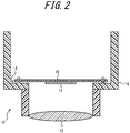
- the imaging apparatus 10 includes an optical system 12, an image sensor 13, and a fixing structure 14, as illustrated in FIG. 2 .
- the optical system 12 includes an optical element such as a lens.
- the optical system 12 is designed so that its optical properties such as angle of view and depth of field will be desired values, and formed.
- the optical system 12 forms a subject image.
- the optical system 12 is held by a housing 16 included in the below-described fixing structure 14.
- the image sensor 13 is, for example, a charge coupled device (CCD) image sensor or a complementary metal oxide semiconductor (CMOS) image sensor.
- the image sensor 13 is mounted on a circuit board that is a plate-like member 15 included in the below-described fixing structure 14.
- the image sensor 13 is located at an image formation position of the optical system 12, via the plate-like member 15 and the housing 16.
- the image sensor 13 captures the subject image formed by the optical system 12.
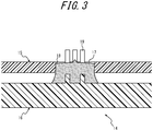
- the fixing structure 14 includes the plate-like member 15, the housing 16, and an adhesion body 17, as illustrated in FIG. 3 .
- the plate-like member 15 is, for example, a circuit board, as mentioned above.
- the plate-like member 15 has an engaging portion 18 in part of its plate surface.
- the engaging portion 18 may include, for example, at least one of a through hole from one plate surface to the other plate surface and a notch from an end at a plate surface.
- the whole engaging portion 18 may be a through hole, the whole engaging portion 18 may be a notch, or the engaging portion 18 may be a through hole in one part and a notch in another part.
- the housing 16 has a protrusion 19 at a position at which the plate-like member 15 is fixed.
- the protrusion 19 is, for example, a boss that is cylindrical as a whole.
- the protrusion 19 protrudes perpendicularly to the inner wall surface of the housing 16 and inwardly, inside the housing 16 in which the plate-like member 15 is provided. More specifically, the protrusion 19 protrudes in parallel with the optical axis direction of the optical system 12 held by the housing 16, in a direction away from the optical system 12.
- the protrusion 19 is provided so that the plate-like member 15 can be located substantially at a predetermined position with respect to the housing 16 in a state in which the protrusion 19 and the engaging portion 18 of the plate-like member 15 are loosely fitted together.
- the outer diameter of the protrusion 19 is smaller than the inner diameter of the engaging portion 18 of the plate-like member 15. In a state in which the protrusion 19 is inserted in the engaging portion 18, a gap can be formed between the outer peripheral wall surface of the protrusion 19 and the inner peripheral wall surface of the engaging portion 18.
- the protrusion 19 has a recess 20 formed from the tip along the protruding direction.
- the protrusion 19 has a plurality of communicating portions 21.
- each communicating portion 21 communicates between the recess 20, i.e. the internal space, of the protrusion 19 in the part having the recess 20 and the outer periphery of the protrusion 19, i.e. the surrounding space os outside the peripheral wall defining the recess 20.
- the plurality of communicating portions 21 are distributed around an axis extending in the protruding direction.
- the axis extending in the protruding direction is an axis passing through the center of gravity of the protrusion 19 in a section perpendicular to the protruding direction.
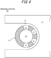
- the plurality of communicating portions 21 may or may not be arranged at equal intervals around the axis extending in the protruding direction. In this embodiment, the plurality of communicating portions 21 are arranged at equal intervals around the axis extending in the protruding direction. In a configuration in which the engaging portion 18 is a notch, the communicating portions 21 may be located only in a part facing the inner peripheral wall defining the engaging portion 18, as illustrated in FIG. 6 .
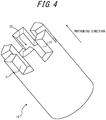
- each communicating portion 21 may have a shape of a slit extending from the tip of the protrusion 19 along the protruding direction, as illustrated in FIG. 4 .
- each communicating portion 21 may have a shape of a hole extending from the inner peripheral wall surface of the protrusion 19 defining the recess 20 to the outer peripheral wall surface of the protrusion 19, as illustrated in FIG. 7 .
- each communicating portion 21 may have a shape of a notch located near the tip of the protrusion 19, as illustrated in FIG. 8 .
- the plurality of communicating portions 21 may have the same shape or different shapes.
- the bottom surface of the recess 20 may be farther from the tip of the protrusion 19 than a part that is farthest from the tip of the protrusion 19 from among the communicating wall surfaces defining the communicating portion 21, as illustrated in FIG. 4 .
- the bottom surface of the recess 20 may be closer to the tip of the protrusion 19 than the part farthest from the tip of the protrusion 19, as illustrated in FIG. 9 .
- the fixing structure 14 at least part of the outer peripheral wall surface of the protrusion 19 faces the inner peripheral wall surface defining the engaging portion 18, as illustrated in FIG. 3 .
- the protrusion 19 is inserted in the engaging portion 18.
- the adhesion body 17 is interposed between the engaging portion 18 and the protrusion 19, and fixes the plate-like member 15 to the housing 16.
- the adhesion body 17 is a cured adhesive.
- the adhesive include photo-curing resin and thermosetting resin.
- the adhesion body 17 is located from the recess 20 to a space between the engaging portion 18 and the protrusion 19 through the plurality of communicating portions 21.
- the adhesion body 17 projects from the protrusion 19 through the plurality of communicating portions 21 from the recess 20 and reaches the engaging portion 18.
- the housing 16 having the protrusion 19 of the foregoing configuration is supported so that the protruding direction of the protrusion 19 will be vertically upward, as illustrated in FIG. 10 .
- the protruding direction of the protrusion 19 is not limited to vertically upward, and the housing 16 may be supported so that the protruding direction of the protrusion 19 will be a horizontal direction.
- the plate-like member 15 of the foregoing configuration is placed in the housing 16 so that the protrusion 19 will be inserted into the engaging portion 18, as illustrated in FIG. 11 .
- a jig that supports the plate-like member 15 so as to be displaceable three-dimensionally is used.
- the protrusion 19 By inserting the protrusion 19 into the engaging portion 18, rough alignment of the plate-like member 15 in the housing 16 is carried out.
- an injector 22 for an adhesive is inserted into the recess 20 of the protrusion 19, as illustrated in FIG. 13 .
- the injector 22 may have a small-diameter inlet from which the adhesive can be injected into the recess 20, like a needle.
- an adhesive 23 is discharged from the injector 22 as illustrated in FIG. 14 , thus starting the injection of the adhesive 23 into the recess 20.
- the injection of the adhesive 23 is stopped once the adhesive 23 has reached the engaging portion 18 as a result of flowing out of the recess 20 to the outer periphery of the protrusion 19 through the communicating portions 21, as illustrated in FIG. 15 .
- the injector 22 is extracted and removed from the recess 20, and the adhesive 23 is cured.
- the adhesive 23 is photo-curing resin
- the adhesive 23 is irradiated with light of a wavelength for curing the resin.
- the adhesive 23 is thermosetting resin
- the adhesive 23 is heated to the curing temperature of the resin. As a result of curing the adhesive 23, the fixing structure 14 is manufactured.
- the adhesion body 17 for fixing the plate-like member 15 to the housing 16 is located from the recess 20 of the protrusion 19 of the housing 16 to a space between the engaging portion 18 and the protrusion 19 through the plurality of communicating portions 21 distributed around the axis extending in the protruding direction.
- the adhesion body 17 can be uniformly formed around the axis extending in the protruding direction of the protrusion 19.
- the adhesion body 17 can be uniformly formed around the protruding direction, so that the plate-like member 15 can be aligned in the housing 16 with high accuracy.
- the plurality of communicating portions 21 are arranged at equal intervals around the axis extending in the protruding direction.
- the adhesion body 17 can be more uniformly formed around the axis extending in the protruding direction of the protrusion 19.
- the plate-like member 15 can be aligned in the housing 16 with higher accuracy.
- the bottom surface of the recess 20 may be farther from the tip of the protrusion 19 than a part that is farthest from the tip of the protrusion 19 from among the communicating wall surfaces defining the communicating portion 21.
- the bottom surface of the recess 20 may be closer to the tip of the protrusion 19 than a part that is farthest from the tip of the protrusion 19 from among the communicating wall surfaces defining the communicating portion 21. With such a configuration, the amount of the adhesive 23 used in the fixing structure 14 can be reduced.
Landscapes
- Engineering & Computer Science (AREA)
- Multimedia (AREA)
- Signal Processing (AREA)
- Physics & Mathematics (AREA)
- General Physics & Mathematics (AREA)
- Optics & Photonics (AREA)
- Microelectronics & Electronic Packaging (AREA)
- Mechanical Engineering (AREA)
- Studio Devices (AREA)
- Transforming Light Signals Into Electric Signals (AREA)
- Mounting Components In General For Electric Apparatus (AREA)
- Adhesives Or Adhesive Processes (AREA)
- Mounting Of Printed Circuit Boards And The Like (AREA)
- Mounting And Adjusting Of Optical Elements (AREA)
Abstract
Description
- This application claims priority to and the benefit of Japanese Patent Application No.
2018-45769 filed on March 13, 2018 - The present disclosure relates to a fixing structure, an electronic apparatus, an imaging apparatus, a moveable body, and a fixing structure manufacturing method.
- Fixing structures that can precisely align and fix a plate-like member in a housing, such as a structure in which a circuit board carrying an image sensor is fixed to a housing holding an optical system, have conventionally been studied. Not only precise alignment but also simplified manufacture is required. To achieve precise alignment with simplified manufacture, a technique of performing alignment in a state in which a protrusion and a notch with a gap therebetween are loosely fitted and fixing members using an adhesive is proposed (see
JP 2004-010759 A - PTL 1:
JP 2004-010759 A - A fixing structure according to a first aspect comprises: a plate-like member having an engaging portion that includes at least one of a through hole and a notch; a housing having a protrusion whose outer peripheral wall surface at least partly faces an inner peripheral wall surface defining the engaging portion and that has a recess formed from a tip thereof along a protruding direction thereof; and an adhesion body interposed between the engaging portion and the protrusion and fixing the plate-like member to the housing, wherein the protrusion has a plurality of communicating portions that communicate between the recess and an outer periphery of the protrusion and are distributed around an axis extending in the protruding direction, and the adhesion body is located from the recess to a space between the engaging portion and the protrusion through the plurality of communicating portions.
- An electronic apparatus according to a second aspect comprises: a circuit board having an engaging portion that includes at least one of a through hole and a notch; a housing having a protrusion whose outer peripheral wall surface at least partly faces an inner peripheral wall surface defining the engaging portion and that has a recess formed from a tip thereof along a protruding direction thereof; and an adhesion body interposed between the engaging portion and the protrusion and fixing the circuit board to the housing, wherein the protrusion has a plurality of communicating portions that communicate between the recess and an outer periphery of the protrusion and are distributed around an axis extending in the protruding direction, and the adhesion body is located from the recess to a space between the engaging portion and the protrusion through the plurality of communicating portions.
- An imaging apparatus according to a third aspect comprises: a circuit board having an engaging portion that includes at least one of a through hole and a notch; an image sensor mounted on the circuit board; a housing having a protrusion whose outer peripheral wall surface at least partly faces an inner peripheral wall surface defining the engaging portion and that has a recess formed from a tip thereof along a protruding direction thereof; and an adhesion body interposed between the engaging portion and the protrusion and fixing the circuit board to the housing, wherein the protrusion has a plurality of communicating portions that communicate between the recess and an outer periphery of the protrusion and are distributed around an axis extending in the protruding direction, and the adhesion body is located from the recess to a space between the engaging portion and the protrusion through the plurality of communicating portions.
- A moveable body according to a fourth aspect comprises an imaging apparatus including: a circuit board having an engaging portion that includes at least one of a through hole and a notch; an image sensor mounted on the circuit board; a housing having a protrusion whose outer peripheral wall surface at least partly faces an inner peripheral wall surface defining the engaging portion and that has a recess formed from a tip thereof along a protruding direction thereof; and an adhesion body interposed between the engaging portion and the protrusion and fixing the plate-like member to the housing, wherein the protrusion has a plurality of communicating portions that communicate between the recess and an outer periphery of the protrusion and are distributed around an axis extending in the protruding direction, and the adhesion body is located from the recess to a space between the engaging portion and the protrusion through the plurality of communicating portions.
- A fixing structure manufacturing method according to a fifth aspect comprises: supporting a housing having a protrusion in a state in which a protruding direction of the protrusion is vertically upward; inserting the protrusion into an engaging portion of a plate-like member, the engaging portion including at least one of a through hole and a notch; performing alignment of the plate-like member in the housing; starting injection of an adhesive into a recess formed in the protrusion from a tip thereof along a protruding direction thereof; stopping the injection of the adhesive after the adhesive has reached the engaging portion as a result of flowing out of the recess through a plurality of communicating portions of the protrusion, the plurality of communicating portions communicating between the recess and an outer periphery of the protrusion and being distributed around an axis extending in the protruding direction; and curing the adhesive that has reached the engaging portion.
- In the accompanying drawings:
-
FIG. 1 is a diagram illustrating a mounting position, in a moveable body, of an imaging apparatus using a fixing structure according to an embodiment; -
FIG. 2 is a sectional diagram illustrating a schematic configuration of the imaging apparatus inFIG. 1 , taken along an optical axis; -
FIG. 3 is an enlarged sectional diagram illustrating a schematic configuration of the fixing structure inFIG. 2 ; -
FIG. 4 is a perspective diagram illustrating the appearance of a protrusion inFIG. 3 ; -
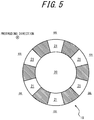
FIG. 5 is a sectional diagram illustrating a section of the protrusion inFIG. 4 perpendicular to its protruding direction; -
FIG. 6 is a sectional diagram illustrating a section of a modification of the protrusion inFIG. 4 perpendicular to its protruding direction, in a configuration in which an engaging portion is a notch; -
FIG. 7 is a perspective diagram illustrating the appearance of another example of the protrusion inFIG. 3 ; -
FIG. 8 is a perspective diagram illustrating the appearance of another example of the protrusion inFIG. 3 ; -
FIG. 9 is a perspective diagram illustrating the appearance of another example of the protrusion inFIG. 3 ; -
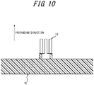
FIG. 10 is a sectional diagram illustrating a manufacturing method for the fixing structure inFIG. 3 , and illustrating a support posture of a housing; -
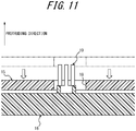
FIG. 11 is a sectional diagram illustrating the manufacturing method for the fixing structure inFIG. 3 , and illustrating a state in which rough alignment of a plate-like member has been performed in the housing; -
FIG. 12 is a sectional diagram illustrating the manufacturing method for the fixing structure inFIG. 3 , and illustrating a state in which precise alignment of the plate-like member has been performed in the housing; -
FIG. 13 is a sectional diagram illustrating the manufacturing method for the fixing structure inFIG. 3 , and illustrating a state in which an injector has been inserted into a recess; -
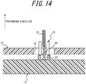
FIG. 14 is a sectional diagram illustrating the manufacturing method for the fixing structure inFIG. 3 , and illustrating a state in which injection of an adhesive into the recess has started; -
FIG. 15 is a sectional diagram illustrating the manufacturing method for the fixing structure inFIG. 3 , and illustrating a state in which the injected adhesive has reached an engaging portion; and -
FIG. 16 is a top diagram illustrating an operation necessary when manufacturing a conventional fixing structure. - An embodiment of a fixing structure to which the present disclosure is applied will be described below, with reference to the drawings.
- A fixing structure according to one of the disclosed embodiments is used, for example, in an electronic apparatus. A specific example of the electronic apparatus is an imaging apparatus. For example, an
imaging apparatus 10 using the fixing structure according to this embodiment is mounted in amoveable body 11, as illustrated inFIG. 1 . - The
moveable body 11 may be, for example, a vehicle, a ship, or an aircraft. Vehicles may include, for example, motor vehicles, industrial vehicles, railed vehicles, domestic vehicles, and fixed-wing airplanes running on runways. Motor vehicles may include, for example, cars, trucks, buses, two-wheeled vehicles, and trolleybuses. Industrial vehicles may include, for example, industrial vehicles for agriculture and construction. Industrial vehicles may include, for example, forklifts and golf carts. Industrial vehicles for agriculture may include, for example, tractors, cultivators, transplanters, binders, combines, and lawn mowers. Industrial vehicles for construction may include, for example, bulldozers, scrapers, power shovels, crane trucks, dump trucks, and road rollers. Vehicles may include human-powered vehicles. The classifications of vehicles are not limited to the above-mentioned examples. For example, motor vehicles may include industrial vehicles that can run on roads. The same type of vehicle may belong to a plurality of classifications. Ships may include, for example, personal watercraft, boats, and tankers. Aircraft may include, for example, fixed-wing airplanes and rotary-wing airplanes. - The
imaging apparatus 10 includes anoptical system 12, animage sensor 13, and afixing structure 14, as illustrated inFIG. 2 . - The
optical system 12 includes an optical element such as a lens. Theoptical system 12 is designed so that its optical properties such as angle of view and depth of field will be desired values, and formed. Theoptical system 12 forms a subject image. Theoptical system 12 is held by ahousing 16 included in the below-describedfixing structure 14. - The
image sensor 13 is, for example, a charge coupled device (CCD) image sensor or a complementary metal oxide semiconductor (CMOS) image sensor. Theimage sensor 13 is mounted on a circuit board that is a plate-like member 15 included in the below-describedfixing structure 14. Theimage sensor 13 is located at an image formation position of theoptical system 12, via the plate-like member 15 and thehousing 16. Theimage sensor 13 captures the subject image formed by theoptical system 12. - The
fixing structure 14 includes the plate-like member 15, thehousing 16, and anadhesion body 17, as illustrated inFIG. 3 . - The plate-
like member 15 is, for example, a circuit board, as mentioned above. The plate-like member 15 has anengaging portion 18 in part of its plate surface. Theengaging portion 18 may include, for example, at least one of a through hole from one plate surface to the other plate surface and a notch from an end at a plate surface. For example, the whole engagingportion 18 may be a through hole, the whole engagingportion 18 may be a notch, or the engagingportion 18 may be a through hole in one part and a notch in another part. - The
housing 16 has aprotrusion 19 at a position at which the plate-like member 15 is fixed. Theprotrusion 19 is, for example, a boss that is cylindrical as a whole. For example, theprotrusion 19 protrudes perpendicularly to the inner wall surface of thehousing 16 and inwardly, inside thehousing 16 in which the plate-like member 15 is provided. More specifically, theprotrusion 19 protrudes in parallel with the optical axis direction of theoptical system 12 held by thehousing 16, in a direction away from theoptical system 12. Theprotrusion 19 is provided so that the plate-like member 15 can be located substantially at a predetermined position with respect to thehousing 16 in a state in which theprotrusion 19 and the engagingportion 18 of the plate-like member 15 are loosely fitted together. The outer diameter of theprotrusion 19 is smaller than the inner diameter of the engagingportion 18 of the plate-like member 15. In a state in which theprotrusion 19 is inserted in the engagingportion 18, a gap can be formed between the outer peripheral wall surface of theprotrusion 19 and the inner peripheral wall surface of the engagingportion 18. - As illustrated in
FIG. 4 , theprotrusion 19 has arecess 20 formed from the tip along the protruding direction. Theprotrusion 19 has a plurality of communicatingportions 21. As illustrated inFIG. 5 , each communicatingportion 21 communicates between therecess 20, i.e. the internal space, of theprotrusion 19 in the part having therecess 20 and the outer periphery of theprotrusion 19, i.e. the surrounding space os outside the peripheral wall defining therecess 20. The plurality of communicatingportions 21 are distributed around an axis extending in the protruding direction. The axis extending in the protruding direction is an axis passing through the center of gravity of theprotrusion 19 in a section perpendicular to the protruding direction. The plurality of communicatingportions 21 may or may not be arranged at equal intervals around the axis extending in the protruding direction. In this embodiment, the plurality of communicatingportions 21 are arranged at equal intervals around the axis extending in the protruding direction. In a configuration in which the engagingportion 18 is a notch, the communicatingportions 21 may be located only in a part facing the inner peripheral wall defining the engagingportion 18, as illustrated inFIG. 6 . - For example, each communicating
portion 21 may have a shape of a slit extending from the tip of theprotrusion 19 along the protruding direction, as illustrated inFIG. 4 . For example, each communicatingportion 21 may have a shape of a hole extending from the inner peripheral wall surface of theprotrusion 19 defining therecess 20 to the outer peripheral wall surface of theprotrusion 19, as illustrated inFIG. 7 . For example, each communicatingportion 21 may have a shape of a notch located near the tip of theprotrusion 19, as illustrated inFIG. 8 . The plurality of communicatingportions 21 may have the same shape or different shapes. - The bottom surface of the
recess 20 may be farther from the tip of theprotrusion 19 than a part that is farthest from the tip of theprotrusion 19 from among the communicating wall surfaces defining the communicatingportion 21, as illustrated inFIG. 4 . Alternatively, the bottom surface of therecess 20 may be closer to the tip of theprotrusion 19 than the part farthest from the tip of theprotrusion 19, as illustrated inFIG. 9 . - In the fixing
structure 14, at least part of the outer peripheral wall surface of theprotrusion 19 faces the inner peripheral wall surface defining the engagingportion 18, as illustrated inFIG. 3 . In other words, in the fixingstructure 14, theprotrusion 19 is inserted in the engagingportion 18. - The
adhesion body 17 is interposed between the engagingportion 18 and theprotrusion 19, and fixes the plate-like member 15 to thehousing 16. Specifically, theadhesion body 17 is a cured adhesive. Examples of the adhesive include photo-curing resin and thermosetting resin. As illustrated inFIG. 3 , theadhesion body 17 is located from therecess 20 to a space between the engagingportion 18 and theprotrusion 19 through the plurality of communicatingportions 21. In detail, theadhesion body 17 projects from theprotrusion 19 through the plurality of communicatingportions 21 from therecess 20 and reaches the engagingportion 18. - A manufacturing method for the fixing
structure 14 will be described below. - To manufacture the fixing
structure 14, thehousing 16 having theprotrusion 19 of the foregoing configuration is supported so that the protruding direction of theprotrusion 19 will be vertically upward, as illustrated inFIG. 10 . For example, in a configuration in which an adhesive having high viscosity is used, the protruding direction of theprotrusion 19 is not limited to vertically upward, and thehousing 16 may be supported so that the protruding direction of theprotrusion 19 will be a horizontal direction. After thehousing 16 is supported, the plate-like member 15 of the foregoing configuration is placed in thehousing 16 so that theprotrusion 19 will be inserted into the engagingportion 18, as illustrated inFIG. 11 . To place the plate-like member 15 in thehousing 16, for example, a jig that supports the plate-like member 15 so as to be displaceable three-dimensionally is used. By inserting theprotrusion 19 into the engagingportion 18, rough alignment of the plate-like member 15 in thehousing 16 is carried out. - By displacing the plate-
like member 15 in the protruding direction and in a direction perpendicular to the protruding direction as illustrated inFIG. 12 , precise alignment of the plate-like member 15 in thehousing 16 is carried out. In a configuration in which the fixingstructure 14 fixes theimage sensor 13 as in this embodiment, precise alignment to match the position of the light receiving surface of theimage sensor 13 to the focusing position of theoptical system 12 in the protruding direction of theprotrusion 19 is required. Moreover, in this configuration, precise alignment to match the center of the imaging region of theimage sensor 13 to the optical axis of theoptical system 12 in the direction perpendicular to the protruding direction of theprotrusion 19 is required. In the example inFIG. 12 , the precise alignment is performed by displacing the plate-like member 15 in the protruding direction and leftward in the drawing from the position in the rough alignment (indicated by dashed-two dotted lines). - After the precise alignment, an
injector 22 for an adhesive is inserted into therecess 20 of theprotrusion 19, as illustrated inFIG. 13 . Theinjector 22 may have a small-diameter inlet from which the adhesive can be injected into therecess 20, like a needle. In a state in which theinjector 22 is inserted in therecess 20, an adhesive 23 is discharged from theinjector 22 as illustrated inFIG. 14 , thus starting the injection of the adhesive 23 into therecess 20. - After the injection of the adhesive 23 is started, the injection of the adhesive 23 is stopped once the adhesive 23 has reached the engaging
portion 18 as a result of flowing out of therecess 20 to the outer periphery of theprotrusion 19 through the communicatingportions 21, as illustrated inFIG. 15 . After the injection is stopped, theinjector 22 is extracted and removed from therecess 20, and the adhesive 23 is cured. In the case where the adhesive 23 is photo-curing resin, the adhesive 23 is irradiated with light of a wavelength for curing the resin. In the case where the adhesive 23 is thermosetting resin, the adhesive 23 is heated to the curing temperature of the resin. As a result of curing the adhesive 23, the fixingstructure 14 is manufactured. - In the fixing
structure 14 according to this embodiment with the foregoing configuration, theadhesion body 17 for fixing the plate-like member 15 to thehousing 16 is located from therecess 20 of theprotrusion 19 of thehousing 16 to a space between the engagingportion 18 and theprotrusion 19 through the plurality of communicatingportions 21 distributed around the axis extending in the protruding direction. With such a configuration, in the fixingstructure 14, theadhesion body 17 can be uniformly formed around the axis extending in the protruding direction of theprotrusion 19. Since the adhesive shrinks on curing, if theadhesion body 17 between theprotrusion 19 and the engagingportion 18 is not uniformly formed around the axis extending in the protruding direction, there is a possibility that the plate-like member 15 deviates from the position of alignment. For example, in the fixing structure described in PTL 1, after alignment of a circuit board 15' in a housing 16', an adhesive needs to be applied in the gap between a hole 18' and a protrusion 19' in the circumferential direction of the protrusion 19', as illustrated inFIG. 16 . However, uniformly applying the adhesive in the gap between the hole 18'and the protrusion 19' in the circumferential direction of the protrusion 19' requires high skill as, for example, the operator needs to discharge the adhesive while displacing an injector 22' in the circumferential direction. Thus, alignment of high accuracy is difficult. In the fixingstructure 14 of the foregoing configuration, on the other hand, theadhesion body 17 can be uniformly formed around the protruding direction, so that the plate-like member 15 can be aligned in thehousing 16 with high accuracy. - In the fixing
structure 14 according to this embodiment, the plurality of communicatingportions 21 are arranged at equal intervals around the axis extending in the protruding direction. With such a configuration, in the fixingstructure 14, theadhesion body 17 can be more uniformly formed around the axis extending in the protruding direction of theprotrusion 19. Hence, in the fixingstructure 14, the plate-like member 15 can be aligned in thehousing 16 with higher accuracy. - In the fixing
structure 14 according to this embodiment, the bottom surface of therecess 20 may be farther from the tip of theprotrusion 19 than a part that is farthest from the tip of theprotrusion 19 from among the communicating wall surfaces defining the communicatingportion 21. With such a configuration, even in the case where, when manufacturing the fixingstructure 14, the insertion position of theinjector 22 in therecess 20 deviates from the center of therecess 20 as seen from the protruding direction, the liquid surface of the adhesive 23 can become level before it rises to the communicatingportions 21. Accordingly, in the manufacture of the fixingstructure 14, the adhesive 23 can be uniformly flown out through each communicatingportion 21 regardless of the distance from the insertion position to the communicatingportion 21. Hence, in the fixingstructure 14, theadhesion body 17 can be uniformly formed around the axis extending in the protruding direction regardless of the insertion position of theinjector 22 in therecess 20 in the manufacture. - In the fixing
structure 14 according to this embodiment, the bottom surface of therecess 20 may be closer to the tip of theprotrusion 19 than a part that is farthest from the tip of theprotrusion 19 from among the communicating wall surfaces defining the communicatingportion 21. With such a configuration, the amount of the adhesive 23 used in the fixingstructure 14 can be reduced. - While some embodiments of the present disclosure have been described above by way of drawings and examples, various changes and modifications may be easily made by those of ordinary skill in the art based on the present disclosure. Such various changes and modifications are therefore included in the scope of the present disclosure.
-
- 10
- imaging apparatus
- 11
- moveable body
- 12
- optical system
- 13
- image sensor
- 14
- fixing structure
- 15
- plate-like member
- 15'
- circuit board
- 16, 16'
- housing
- 17
- adhesion body
- 18
- engaging portion
- 18'
- hole
- 19, 19'
- protrusion
- 20
- recess
- 21
- communicating portion
- 22, 22'
- injector
- 23
- adhesive
- os
- surrounding space
Claims (9)
- A fixing structure comprising:a plate-like member having an engaging portion that includes at least one of a through hole and a notch;a housing having a protrusion whose outer peripheral wall surface at least partly faces an inner peripheral wall surface defining the engaging portion and that has a recess formed from a tip thereof along a protruding direction thereof; andan adhesion body interposed between the engaging portion and the protrusion and fixing the plate-like member to the housing,wherein the protrusion has a plurality of communicating portions that communicate between the recess and an outer periphery of the protrusion and are distributed around an axis extending in the protruding direction, andthe adhesion body is located from the recess to a space between the engaging portion and the protrusion through the plurality of communicating portions.
- The fixing structure according to claim 1, wherein the plurality of communicating portions are arranged at equal intervals around the axis extending in the protruding direction.
- The fixing structure according to claim 1 or 2, wherein the plurality of communicating portions have a shape of a slit extending from the tip of the protrusion along the protruding direction.
- The fixing structure according to claim 1 or 2, wherein the plurality of communicating portions have a shape of a hole extending from an inner peripheral wall surface defining the recess to the outer peripheral wall surface.
- The fixing structure according to claim 1 or 2, wherein the plurality of communicating portions have a shape of a notch located near the tip of the protrusion.
- An electronic apparatus comprising:a circuit board having an engaging portion that includes at least one of a through hole and a notch;a housing having a protrusion whose outer peripheral wall surface at least partly faces an inner peripheral wall surface defining the engaging portion and that has a recess formed from a tip thereof along a protruding direction thereof; andan adhesion body interposed between the engaging portion and the protrusion and fixing the circuit board to the housing,wherein the protrusion has a plurality of communicating portions that communicate between the recess and an outer periphery of the protrusion and are distributed around an axis extending in the protruding direction, andthe adhesion body is located from the recess to a space between the engaging portion and the protrusion through the plurality of communicating portions.
- An imaging apparatus comprising:a circuit board having an engaging portion that includes at least one of a through hole and a notch;an image sensor mounted on the circuit board;a housing having a protrusion whose outer peripheral wall surface at least partly faces an inner peripheral wall surface defining the engaging portion and that has a recess formed from a tip thereof along a protruding direction thereof; andan adhesion body interposed between the engaging portion and the protrusion and fixing the circuit board to the housing,wherein the protrusion has a plurality of communicating portions that communicate between the recess and an outer periphery of the protrusion and are distributed around an axis extending in the protruding direction, andthe adhesion body is located from the recess to a space between the engaging portion and the protrusion through the plurality of communicating portions.
- A moveable body comprising the imaging apparatus according to claim 7.
- A fixing structure manufacturing method comprising:supporting a housing having a protrusion;inserting the protrusion into an engaging portion of a plate-like member, the engaging portion including at least one of a through hole and a notch;performing alignment of the plate-like member in the housing;starting injection of an adhesive into a recess formed in the protrusion from a tip thereof along a protruding direction thereof;stopping the injection of the adhesive after the adhesive has reached the engaging portion as a result of flowing out of the recess through a plurality of communicating portions of the protrusion, the plurality of communicating portions communicating between the recess and an outer periphery of the protrusion and being distributed around an axis extending in the protruding direction; andcuring the adhesive that has reached the engaging portion.
Applications Claiming Priority (2)
| Application Number | Priority Date | Filing Date | Title |
|---|---|---|---|
| JP2018045769A JP6976201B2 (en) | 2018-03-13 | 2018-03-13 | Manufacturing Methods for Fixed Structures, Electronic Devices, Imaging Devices, Mobiles, and Fixed Structures |
| PCT/JP2019/003715 WO2019176363A1 (en) | 2018-03-13 | 2019-02-01 | Securing structure, electronic device, imaging device, moving body, and securing structure production method |
Publications (3)
| Publication Number | Publication Date |
|---|---|
| EP3768052A1 true EP3768052A1 (en) | 2021-01-20 |
| EP3768052A4 EP3768052A4 (en) | 2021-12-01 |
| EP3768052B1 EP3768052B1 (en) | 2024-01-24 |
Family
ID=67907650
Family Applications (1)
| Application Number | Title | Priority Date | Filing Date |
|---|---|---|---|
| EP19767031.8A Active EP3768052B1 (en) | 2018-03-13 | 2019-02-01 | Securing structure, electronic device, imaging device, moving body, and securing structure production method |
Country Status (5)
| Country | Link |
|---|---|
| US (1) | US20210014995A1 (en) |
| EP (1) | EP3768052B1 (en) |
| JP (1) | JP6976201B2 (en) |
| CN (1) | CN111788873B (en) |
| WO (1) | WO2019176363A1 (en) |
Family Cites Families (30)
| Publication number | Priority date | Publication date | Assignee | Title |
|---|---|---|---|---|
| JP3305426B2 (en) * | 1993-06-25 | 2002-07-22 | 日立化成工業株式会社 | Manufacturing method of multilayer printed wiring board |
| EP0790652B1 (en) * | 1995-08-02 | 2007-02-21 | Matsushita Electric Industrial Co., Ltd. | Solid-state image pickup device and its manufacture |
| JP3103077B2 (en) * | 1999-01-08 | 2000-10-23 | 初雄 藤田 | JOINING DEVICE, JOINING APPARATUS FOR COLUMN, BEAM, GIRDER USING THE SAME, AND JOINING METHOD FOR COLUMN, BEAM, GIRDER, etc. |
| JP2000252652A (en) * | 1999-02-26 | 2000-09-14 | Denso Corp | Board holding device for control equipment |
| JP2001245217A (en) * | 2000-03-02 | 2001-09-07 | Olympus Optical Co Ltd | Small imaging module |
| JP3490694B2 (en) * | 2001-03-28 | 2004-01-26 | 三菱電機株式会社 | Imaging device and method of manufacturing the same |
| JP2004010759A (en) * | 2002-06-07 | 2004-01-15 | Sankyo Seiki Mfg Co Ltd | Bonded structure, optical head device and bonding method |
| KR100718421B1 (en) * | 2002-06-28 | 2007-05-14 | 교세라 가부시키가이샤 | Imaging device package, camera module and camera module producing method |
| US20040061799A1 (en) * | 2002-09-27 | 2004-04-01 | Konica Corporation | Image pickup device and portable terminal equipped therewith |
| JP2007028430A (en) * | 2005-07-20 | 2007-02-01 | Kyocera Corp | The camera module |
| JP2007150708A (en) * | 2005-11-28 | 2007-06-14 | Kyocera Corp | Imaging module and imaging apparatus |
| JP2007184801A (en) * | 2006-01-10 | 2007-07-19 | Alps Electric Co Ltd | The camera module |
| WO2007099845A1 (en) * | 2006-03-02 | 2007-09-07 | Konica Minolta Opto, Inc. | Imaging device |
| JP4805705B2 (en) * | 2006-03-23 | 2011-11-02 | アルプス電気株式会社 | The camera module |
| JP5448823B2 (en) * | 2007-09-19 | 2014-03-19 | パナソニック株式会社 | Optical pickup, optical information device, computer, optical disc player, car navigation system, optical disc recorder, and optical disc server |
| WO2010095627A1 (en) * | 2009-02-23 | 2010-08-26 | 京セラ株式会社 | Imaging module |
| JP5391913B2 (en) * | 2009-08-05 | 2014-01-15 | ソニー株式会社 | Camera device |
| EP2495456A4 (en) * | 2009-10-29 | 2013-05-22 | Yachiyo Ind Co Ltd | COMPONENT ASSEMBLY STRUCTURE AND SOCKET NUT |
| JP5126257B2 (en) * | 2010-03-12 | 2013-01-23 | オムロン株式会社 | Imaging device |
| KR20130120981A (en) * | 2010-06-28 | 2013-11-05 | 쿄세라 코포레이션 | Wiring substrate, image pickup device, and image-pickup device module |
| US20130223951A1 (en) * | 2011-04-28 | 2013-08-29 | Masahiro Bessho | Cap and fixing structure using the same |
| JP2013248233A (en) * | 2012-06-01 | 2013-12-12 | Yamana Seisakusho:Kk | Hook and method of attaching the same |
| JP2014017435A (en) * | 2012-07-11 | 2014-01-30 | Panasonic Corp | Electronic device |
| US9363914B2 (en) * | 2012-07-13 | 2016-06-07 | Mitubishi Electric Corporation | Semiconductor device |
| WO2015016270A1 (en) * | 2013-07-30 | 2015-02-05 | 京セラ株式会社 | Substrate for mounting imaging element, and imaging device |
| CN103489885B (en) * | 2013-09-30 | 2016-05-11 | 格科微电子(上海)有限公司 | The wafer-level packaging method of image sensor chip |
| CN104101980B (en) * | 2014-06-30 | 2017-06-27 | 南昌欧菲光电技术有限公司 | Camera module |
| JP6583601B2 (en) * | 2014-08-06 | 2019-10-02 | ミツミ電機株式会社 | Lens holder driving device and camera-equipped mobile terminal |
| JP6503735B2 (en) * | 2014-12-26 | 2019-04-24 | ミツミ電機株式会社 | Lens drive device, camera module, and camera mounted device |
| US10562467B2 (en) * | 2016-04-28 | 2020-02-18 | Kyocera Corporation | Bonding structure, imaging apparatus, and on-vehicle camera |
-
2018
- 2018-03-13 JP JP2018045769A patent/JP6976201B2/en active Active
-
2019
- 2019-02-01 WO PCT/JP2019/003715 patent/WO2019176363A1/en not_active Ceased
- 2019-02-01 EP EP19767031.8A patent/EP3768052B1/en active Active
- 2019-02-01 CN CN201980016222.3A patent/CN111788873B/en active Active
- 2019-02-01 US US16/977,849 patent/US20210014995A1/en not_active Abandoned
Also Published As
| Publication number | Publication date |
|---|---|
| CN111788873B (en) | 2021-07-23 |
| JP2019161014A (en) | 2019-09-19 |
| EP3768052B1 (en) | 2024-01-24 |
| US20210014995A1 (en) | 2021-01-14 |
| EP3768052A4 (en) | 2021-12-01 |
| CN111788873A (en) | 2020-10-16 |
| JP6976201B2 (en) | 2021-12-08 |
| WO2019176363A1 (en) | 2019-09-19 |
Similar Documents
| Publication | Publication Date | Title |
|---|---|---|
| KR102119329B1 (en) | Lens device, camera, vehicle and method for automotive cameras with improved adhesion area | |
| CN109143523B (en) | Lens unit and method for manufacturing the same | |
| US11363178B2 (en) | Camera module | |
| EP0630486B1 (en) | Process for producing a hybrid integrated optical circuit and device for emitting light waves | |
| CN109791344B (en) | Image pickup apparatus | |
| US20210103119A1 (en) | Vehicular camera with adhesive disposed between non-axially opposed surfaces of the lens barrel and pcb structure | |
| US9802386B2 (en) | Product having plurality of components fixed to each other by adhesive | |
| WO2018055905A1 (en) | Imaging device | |
| KR102860546B1 (en) | Optical connector module and method for manufacturing optical waveguide substrate | |
| JP7103818B2 (en) | Lens unit | |
| CN110178361A (en) | Housing parts for camera case | |
| CN110719386A (en) | Camera module | |
| EP3768052B1 (en) | Securing structure, electronic device, imaging device, moving body, and securing structure production method | |
| US20250133281A1 (en) | Vehicular camera | |
| US20110051454A1 (en) | Light-transmission apparatus and method to produce same | |
| US12346005B2 (en) | Automotive camera with improved housing alignment | |
| US5077821A (en) | Means for coupling a coherent fiber-optic bundle to an electro-optical sensor | |
| US20200192053A1 (en) | Lens assembly for an image detection device for a vehicle, image detection device, and method for manufacturing an image detection device | |
| EP3614204B1 (en) | Imaging device | |
| US11543614B2 (en) | Imaging apparatus, mobile object, and manufacturing method | |
| JP6288329B2 (en) | Method for manufacturing product having a plurality of parts fixed to each other with adhesive, and method for assembling and fixing parts | |
| CN111133744A (en) | Imaging device, imaging device manufacturing method, and moving body | |
| CN108407197A (en) | A kind of camera module packaging method | |
| EP3817356B1 (en) | Bonded structure, imaging device, and moving body | |
| CN110446594B (en) | Accessory for connecting to a member |
Legal Events
| Date | Code | Title | Description |
|---|---|---|---|
| STAA | Information on the status of an ep patent application or granted ep patent |
Free format text: STATUS: THE INTERNATIONAL PUBLICATION HAS BEEN MADE |
|
| PUAI | Public reference made under article 153(3) epc to a published international application that has entered the european phase |
Free format text: ORIGINAL CODE: 0009012 |
|
| STAA | Information on the status of an ep patent application or granted ep patent |
Free format text: STATUS: REQUEST FOR EXAMINATION WAS MADE |
|
| 17P | Request for examination filed |
Effective date: 20200904 |
|
| AK | Designated contracting states |
Kind code of ref document: A1 Designated state(s): AL AT BE BG CH CY CZ DE DK EE ES FI FR GB GR HR HU IE IS IT LI LT LU LV MC MK MT NL NO PL PT RO RS SE SI SK SM TR |
|
| AX | Request for extension of the european patent |
Extension state: BA ME |
|
| DAV | Request for validation of the european patent (deleted) | ||
| DAX | Request for extension of the european patent (deleted) | ||
| A4 | Supplementary search report drawn up and despatched |
Effective date: 20211104 |
|
| RIC1 | Information provided on ipc code assigned before grant |
Ipc: H05K 1/02 20060101ALI20211028BHEP Ipc: H05K 7/12 20060101ALI20211028BHEP Ipc: H04N 5/225 20060101ALI20211028BHEP Ipc: G02B 7/02 20210101ALI20211028BHEP Ipc: G02B 7/00 20210101ALI20211028BHEP Ipc: H05K 7/14 20060101AFI20211028BHEP |
|
| P01 | Opt-out of the competence of the unified patent court (upc) registered |
Effective date: 20230508 |
|
| REG | Reference to a national code |
Ref country code: DE Ref legal event code: R079 Free format text: PREVIOUS MAIN CLASS: H05K0007140000 Ipc: H04N0023000000 Ref country code: DE Ref legal event code: R079 Ref document number: 602019045625 Country of ref document: DE Free format text: PREVIOUS MAIN CLASS: H05K0007140000 Ipc: H04N0023000000 |
|
| GRAP | Despatch of communication of intention to grant a patent |
Free format text: ORIGINAL CODE: EPIDOSNIGR1 |
|
| STAA | Information on the status of an ep patent application or granted ep patent |
Free format text: STATUS: GRANT OF PATENT IS INTENDED |
|
| RIC1 | Information provided on ipc code assigned before grant |
Ipc: H05K 1/02 20060101ALI20230811BHEP Ipc: H04N 23/54 20230101ALI20230811BHEP Ipc: H04N 23/51 20230101ALI20230811BHEP Ipc: G02B 7/02 20210101ALI20230811BHEP Ipc: G02B 13/16 20060101ALI20230811BHEP Ipc: H04N 23/00 20230101AFI20230811BHEP |
|
| INTG | Intention to grant announced |
Effective date: 20230904 |
|
| RIN1 | Information on inventor provided before grant (corrected) |
Inventor name: YASUDA, TOSHIYUKI |
|
| GRAS | Grant fee paid |
Free format text: ORIGINAL CODE: EPIDOSNIGR3 |
|
| GRAA | (expected) grant |
Free format text: ORIGINAL CODE: 0009210 |
|
| STAA | Information on the status of an ep patent application or granted ep patent |
Free format text: STATUS: THE PATENT HAS BEEN GRANTED |
|
| AK | Designated contracting states |
Kind code of ref document: B1 Designated state(s): AL AT BE BG CH CY CZ DE DK EE ES FI FR GB GR HR HU IE IS IT LI LT LU LV MC MK MT NL NO PL PT RO RS SE SI SK SM TR |
|
| REG | Reference to a national code |
Ref country code: GB Ref legal event code: FG4D |
|
| REG | Reference to a national code |
Ref country code: CH Ref legal event code: EP |
|
| REG | Reference to a national code |
Ref country code: IE Ref legal event code: FG4D |
|
| REG | Reference to a national code |
Ref country code: DE Ref legal event code: R096 Ref document number: 602019045625 Country of ref document: DE |
|
| REG | Reference to a national code |
Ref country code: LT Ref legal event code: MG9D |
|
| REG | Reference to a national code |
Ref country code: NL Ref legal event code: MP Effective date: 20240124 |
|
| PG25 | Lapsed in a contracting state [announced via postgrant information from national office to epo] |
Ref country code: NL Free format text: LAPSE BECAUSE OF FAILURE TO SUBMIT A TRANSLATION OF THE DESCRIPTION OR TO PAY THE FEE WITHIN THE PRESCRIBED TIME-LIMIT Effective date: 20240124 |
|
| PG25 | Lapsed in a contracting state [announced via postgrant information from national office to epo] |
Ref country code: NL Free format text: LAPSE BECAUSE OF FAILURE TO SUBMIT A TRANSLATION OF THE DESCRIPTION OR TO PAY THE FEE WITHIN THE PRESCRIBED TIME-LIMIT Effective date: 20240124 |
|
| PG25 | Lapsed in a contracting state [announced via postgrant information from national office to epo] |
Ref country code: IS Free format text: LAPSE BECAUSE OF FAILURE TO SUBMIT A TRANSLATION OF THE DESCRIPTION OR TO PAY THE FEE WITHIN THE PRESCRIBED TIME-LIMIT Effective date: 20240524 |
|
| PG25 | Lapsed in a contracting state [announced via postgrant information from national office to epo] |
Ref country code: LT Free format text: LAPSE BECAUSE OF FAILURE TO SUBMIT A TRANSLATION OF THE DESCRIPTION OR TO PAY THE FEE WITHIN THE PRESCRIBED TIME-LIMIT Effective date: 20240124 |
|
| PG25 | Lapsed in a contracting state [announced via postgrant information from national office to epo] |
Ref country code: GR Free format text: LAPSE BECAUSE OF FAILURE TO SUBMIT A TRANSLATION OF THE DESCRIPTION OR TO PAY THE FEE WITHIN THE PRESCRIBED TIME-LIMIT Effective date: 20240425 |
|
| REG | Reference to a national code |
Ref country code: AT Ref legal event code: MK05 Ref document number: 1653082 Country of ref document: AT Kind code of ref document: T Effective date: 20240124 |
|
| PG25 | Lapsed in a contracting state [announced via postgrant information from national office to epo] |
Ref country code: RS Free format text: LAPSE BECAUSE OF FAILURE TO SUBMIT A TRANSLATION OF THE DESCRIPTION OR TO PAY THE FEE WITHIN THE PRESCRIBED TIME-LIMIT Effective date: 20240424 Ref country code: HR Free format text: LAPSE BECAUSE OF FAILURE TO SUBMIT A TRANSLATION OF THE DESCRIPTION OR TO PAY THE FEE WITHIN THE PRESCRIBED TIME-LIMIT Effective date: 20240124 |
|
| PG25 | Lapsed in a contracting state [announced via postgrant information from national office to epo] |
Ref country code: ES Free format text: LAPSE BECAUSE OF FAILURE TO SUBMIT A TRANSLATION OF THE DESCRIPTION OR TO PAY THE FEE WITHIN THE PRESCRIBED TIME-LIMIT Effective date: 20240124 |
|
| PG25 | Lapsed in a contracting state [announced via postgrant information from national office to epo] |
Ref country code: AT Free format text: LAPSE BECAUSE OF FAILURE TO SUBMIT A TRANSLATION OF THE DESCRIPTION OR TO PAY THE FEE WITHIN THE PRESCRIBED TIME-LIMIT Effective date: 20240124 |
|
| PG25 | Lapsed in a contracting state [announced via postgrant information from national office to epo] |
Ref country code: RS Free format text: LAPSE BECAUSE OF FAILURE TO SUBMIT A TRANSLATION OF THE DESCRIPTION OR TO PAY THE FEE WITHIN THE PRESCRIBED TIME-LIMIT Effective date: 20240424 Ref country code: NO Free format text: LAPSE BECAUSE OF FAILURE TO SUBMIT A TRANSLATION OF THE DESCRIPTION OR TO PAY THE FEE WITHIN THE PRESCRIBED TIME-LIMIT Effective date: 20240424 Ref country code: LT Free format text: LAPSE BECAUSE OF FAILURE TO SUBMIT A TRANSLATION OF THE DESCRIPTION OR TO PAY THE FEE WITHIN THE PRESCRIBED TIME-LIMIT Effective date: 20240124 Ref country code: IS Free format text: LAPSE BECAUSE OF FAILURE TO SUBMIT A TRANSLATION OF THE DESCRIPTION OR TO PAY THE FEE WITHIN THE PRESCRIBED TIME-LIMIT Effective date: 20240524 Ref country code: HR Free format text: LAPSE BECAUSE OF FAILURE TO SUBMIT A TRANSLATION OF THE DESCRIPTION OR TO PAY THE FEE WITHIN THE PRESCRIBED TIME-LIMIT Effective date: 20240124 Ref country code: GR Free format text: LAPSE BECAUSE OF FAILURE TO SUBMIT A TRANSLATION OF THE DESCRIPTION OR TO PAY THE FEE WITHIN THE PRESCRIBED TIME-LIMIT Effective date: 20240425 Ref country code: FI Free format text: LAPSE BECAUSE OF FAILURE TO SUBMIT A TRANSLATION OF THE DESCRIPTION OR TO PAY THE FEE WITHIN THE PRESCRIBED TIME-LIMIT Effective date: 20240124 Ref country code: ES Free format text: LAPSE BECAUSE OF FAILURE TO SUBMIT A TRANSLATION OF THE DESCRIPTION OR TO PAY THE FEE WITHIN THE PRESCRIBED TIME-LIMIT Effective date: 20240124 Ref country code: BG Free format text: LAPSE BECAUSE OF FAILURE TO SUBMIT A TRANSLATION OF THE DESCRIPTION OR TO PAY THE FEE WITHIN THE PRESCRIBED TIME-LIMIT Effective date: 20240124 Ref country code: AT Free format text: LAPSE BECAUSE OF FAILURE TO SUBMIT A TRANSLATION OF THE DESCRIPTION OR TO PAY THE FEE WITHIN THE PRESCRIBED TIME-LIMIT Effective date: 20240124 |
|
| PG25 | Lapsed in a contracting state [announced via postgrant information from national office to epo] |
Ref country code: PT Free format text: LAPSE BECAUSE OF FAILURE TO SUBMIT A TRANSLATION OF THE DESCRIPTION OR TO PAY THE FEE WITHIN THE PRESCRIBED TIME-LIMIT Effective date: 20240524 Ref country code: PL Free format text: LAPSE BECAUSE OF FAILURE TO SUBMIT A TRANSLATION OF THE DESCRIPTION OR TO PAY THE FEE WITHIN THE PRESCRIBED TIME-LIMIT Effective date: 20240124 |
|
| PG25 | Lapsed in a contracting state [announced via postgrant information from national office to epo] |
Ref country code: SE Free format text: LAPSE BECAUSE OF FAILURE TO SUBMIT A TRANSLATION OF THE DESCRIPTION OR TO PAY THE FEE WITHIN THE PRESCRIBED TIME-LIMIT Effective date: 20240124 Ref country code: PT Free format text: LAPSE BECAUSE OF FAILURE TO SUBMIT A TRANSLATION OF THE DESCRIPTION OR TO PAY THE FEE WITHIN THE PRESCRIBED TIME-LIMIT Effective date: 20240524 Ref country code: PL Free format text: LAPSE BECAUSE OF FAILURE TO SUBMIT A TRANSLATION OF THE DESCRIPTION OR TO PAY THE FEE WITHIN THE PRESCRIBED TIME-LIMIT Effective date: 20240124 Ref country code: LV Free format text: LAPSE BECAUSE OF FAILURE TO SUBMIT A TRANSLATION OF THE DESCRIPTION OR TO PAY THE FEE WITHIN THE PRESCRIBED TIME-LIMIT Effective date: 20240124 |
|
| REG | Reference to a national code |
Ref country code: CH Ref legal event code: PL |
|
| PG25 | Lapsed in a contracting state [announced via postgrant information from national office to epo] |
Ref country code: DK Free format text: LAPSE BECAUSE OF FAILURE TO SUBMIT A TRANSLATION OF THE DESCRIPTION OR TO PAY THE FEE WITHIN THE PRESCRIBED TIME-LIMIT Effective date: 20240124 |
|
| PG25 | Lapsed in a contracting state [announced via postgrant information from national office to epo] |
Ref country code: SM Free format text: LAPSE BECAUSE OF FAILURE TO SUBMIT A TRANSLATION OF THE DESCRIPTION OR TO PAY THE FEE WITHIN THE PRESCRIBED TIME-LIMIT Effective date: 20240124 |
|
| PG25 | Lapsed in a contracting state [announced via postgrant information from national office to epo] |
Ref country code: LU Free format text: LAPSE BECAUSE OF NON-PAYMENT OF DUE FEES Effective date: 20240201 |
|
| PG25 | Lapsed in a contracting state [announced via postgrant information from national office to epo] |
Ref country code: CH Free format text: LAPSE BECAUSE OF NON-PAYMENT OF DUE FEES Effective date: 20240229 |
|
| PG25 | Lapsed in a contracting state [announced via postgrant information from national office to epo] |
Ref country code: EE Free format text: LAPSE BECAUSE OF FAILURE TO SUBMIT A TRANSLATION OF THE DESCRIPTION OR TO PAY THE FEE WITHIN THE PRESCRIBED TIME-LIMIT Effective date: 20240124 Ref country code: CZ Free format text: LAPSE BECAUSE OF FAILURE TO SUBMIT A TRANSLATION OF THE DESCRIPTION OR TO PAY THE FEE WITHIN THE PRESCRIBED TIME-LIMIT Effective date: 20240124 |
|
| REG | Reference to a national code |
Ref country code: DE Ref legal event code: R097 Ref document number: 602019045625 Country of ref document: DE |
|
| PG25 | Lapsed in a contracting state [announced via postgrant information from national office to epo] |
Ref country code: SK Free format text: LAPSE BECAUSE OF FAILURE TO SUBMIT A TRANSLATION OF THE DESCRIPTION OR TO PAY THE FEE WITHIN THE PRESCRIBED TIME-LIMIT Effective date: 20240124 |
|
| PG25 | Lapsed in a contracting state [announced via postgrant information from national office to epo] |
Ref country code: SM Free format text: LAPSE BECAUSE OF FAILURE TO SUBMIT A TRANSLATION OF THE DESCRIPTION OR TO PAY THE FEE WITHIN THE PRESCRIBED TIME-LIMIT Effective date: 20240124 Ref country code: SK Free format text: LAPSE BECAUSE OF FAILURE TO SUBMIT A TRANSLATION OF THE DESCRIPTION OR TO PAY THE FEE WITHIN THE PRESCRIBED TIME-LIMIT Effective date: 20240124 Ref country code: LU Free format text: LAPSE BECAUSE OF NON-PAYMENT OF DUE FEES Effective date: 20240201 Ref country code: EE Free format text: LAPSE BECAUSE OF FAILURE TO SUBMIT A TRANSLATION OF THE DESCRIPTION OR TO PAY THE FEE WITHIN THE PRESCRIBED TIME-LIMIT Effective date: 20240124 Ref country code: DK Free format text: LAPSE BECAUSE OF FAILURE TO SUBMIT A TRANSLATION OF THE DESCRIPTION OR TO PAY THE FEE WITHIN THE PRESCRIBED TIME-LIMIT Effective date: 20240124 Ref country code: CZ Free format text: LAPSE BECAUSE OF FAILURE TO SUBMIT A TRANSLATION OF THE DESCRIPTION OR TO PAY THE FEE WITHIN THE PRESCRIBED TIME-LIMIT Effective date: 20240124 Ref country code: CH Free format text: LAPSE BECAUSE OF NON-PAYMENT OF DUE FEES Effective date: 20240229 |
|
| PG25 | Lapsed in a contracting state [announced via postgrant information from national office to epo] |
Ref country code: MC Free format text: LAPSE BECAUSE OF FAILURE TO SUBMIT A TRANSLATION OF THE DESCRIPTION OR TO PAY THE FEE WITHIN THE PRESCRIBED TIME-LIMIT Effective date: 20240124 |
|
| PG25 | Lapsed in a contracting state [announced via postgrant information from national office to epo] |
Ref country code: MC Free format text: LAPSE BECAUSE OF FAILURE TO SUBMIT A TRANSLATION OF THE DESCRIPTION OR TO PAY THE FEE WITHIN THE PRESCRIBED TIME-LIMIT Effective date: 20240124 |
|
| PLBE | No opposition filed within time limit |
Free format text: ORIGINAL CODE: 0009261 |
|
| STAA | Information on the status of an ep patent application or granted ep patent |
Free format text: STATUS: NO OPPOSITION FILED WITHIN TIME LIMIT |
|
| PG25 | Lapsed in a contracting state [announced via postgrant information from national office to epo] |
Ref country code: IT Free format text: LAPSE BECAUSE OF FAILURE TO SUBMIT A TRANSLATION OF THE DESCRIPTION OR TO PAY THE FEE WITHIN THE PRESCRIBED TIME-LIMIT Effective date: 20240124 |
|
| REG | Reference to a national code |
Ref country code: BE Ref legal event code: MM Effective date: 20240229 |
|
| PG25 | Lapsed in a contracting state [announced via postgrant information from national office to epo] |
Ref country code: IT Free format text: LAPSE BECAUSE OF FAILURE TO SUBMIT A TRANSLATION OF THE DESCRIPTION OR TO PAY THE FEE WITHIN THE PRESCRIBED TIME-LIMIT Effective date: 20240124 |
|
| 26N | No opposition filed |
Effective date: 20241025 |
|
| PG25 | Lapsed in a contracting state [announced via postgrant information from national office to epo] |
Ref country code: BE Free format text: LAPSE BECAUSE OF NON-PAYMENT OF DUE FEES Effective date: 20240229 |
|
| PGFP | Annual fee paid to national office [announced via postgrant information from national office to epo] |
Ref country code: GB Payment date: 20241227 Year of fee payment: 7 |
|
| PGFP | Annual fee paid to national office [announced via postgrant information from national office to epo] |
Ref country code: FR Payment date: 20241231 Year of fee payment: 7 |
|
| PG25 | Lapsed in a contracting state [announced via postgrant information from national office to epo] |
Ref country code: IE Free format text: LAPSE BECAUSE OF NON-PAYMENT OF DUE FEES Effective date: 20240201 |
|
| PG25 | Lapsed in a contracting state [announced via postgrant information from national office to epo] |
Ref country code: IE Free format text: LAPSE BECAUSE OF NON-PAYMENT OF DUE FEES Effective date: 20240201 Ref country code: BE Free format text: LAPSE BECAUSE OF NON-PAYMENT OF DUE FEES Effective date: 20240229 |
|
| PGFP | Annual fee paid to national office [announced via postgrant information from national office to epo] |
Ref country code: DE Payment date: 20241231 Year of fee payment: 7 |
|
| PG25 | Lapsed in a contracting state [announced via postgrant information from national office to epo] |
Ref country code: SI Free format text: LAPSE BECAUSE OF FAILURE TO SUBMIT A TRANSLATION OF THE DESCRIPTION OR TO PAY THE FEE WITHIN THE PRESCRIBED TIME-LIMIT Effective date: 20240124 |
|
| PG25 | Lapsed in a contracting state [announced via postgrant information from national office to epo] |
Ref country code: RO Free format text: LAPSE BECAUSE OF FAILURE TO SUBMIT A TRANSLATION OF THE DESCRIPTION OR TO PAY THE FEE WITHIN THE PRESCRIBED TIME-LIMIT Effective date: 20240124 |
|
| PG25 | Lapsed in a contracting state [announced via postgrant information from national office to epo] |
Ref country code: CY Free format text: LAPSE BECAUSE OF FAILURE TO SUBMIT A TRANSLATION OF THE DESCRIPTION OR TO PAY THE FEE WITHIN THE PRESCRIBED TIME-LIMIT; INVALID AB INITIO Effective date: 20190201 |
|
| PG25 | Lapsed in a contracting state [announced via postgrant information from national office to epo] |
Ref country code: HU Free format text: LAPSE BECAUSE OF FAILURE TO SUBMIT A TRANSLATION OF THE DESCRIPTION OR TO PAY THE FEE WITHIN THE PRESCRIBED TIME-LIMIT; INVALID AB INITIO Effective date: 20190201 |
|
| PG25 | Lapsed in a contracting state [announced via postgrant information from national office to epo] |
Ref country code: TR Free format text: LAPSE BECAUSE OF FAILURE TO SUBMIT A TRANSLATION OF THE DESCRIPTION OR TO PAY THE FEE WITHIN THE PRESCRIBED TIME-LIMIT Effective date: 20240124 |