EP3768013B1 - Terminal device, base station device, and communication method - Google Patents
Terminal device, base station device, and communication method Download PDFInfo
- Publication number
- EP3768013B1 EP3768013B1 EP19766703.3A EP19766703A EP3768013B1 EP 3768013 B1 EP3768013 B1 EP 3768013B1 EP 19766703 A EP19766703 A EP 19766703A EP 3768013 B1 EP3768013 B1 EP 3768013B1
- Authority
- EP
- European Patent Office
- Prior art keywords
- pdcch
- resource set
- control resource
- terminal apparatus
- information
- Prior art date
- Legal status (The legal status is an assumption and is not a legal conclusion. Google has not performed a legal analysis and makes no representation as to the accuracy of the status listed.)
- Active
Links
- 238000004891 communication Methods 0.000 title claims description 47
- 238000000034 method Methods 0.000 title claims description 37
- 230000011664 signaling Effects 0.000 claims description 67
- 238000012545 processing Methods 0.000 claims description 66
- 238000012544 monitoring process Methods 0.000 claims description 15
- 230000005540 biological transmission Effects 0.000 description 66
- 238000013507 mapping Methods 0.000 description 38
- 230000002776 aggregation Effects 0.000 description 36
- 238000004220 aggregation Methods 0.000 description 36
- 238000010586 diagram Methods 0.000 description 28
- 238000001514 detection method Methods 0.000 description 20
- 230000006870 function Effects 0.000 description 10
- 230000004044 response Effects 0.000 description 8
- 238000013468 resource allocation Methods 0.000 description 7
- 230000008859 change Effects 0.000 description 5
- 125000004122 cyclic group Chemical group 0.000 description 5
- 230000009467 reduction Effects 0.000 description 5
- 101150071746 Pbsn gene Proteins 0.000 description 4
- 239000000969 carrier Substances 0.000 description 4
- 230000006978 adaptation Effects 0.000 description 3
- 238000013461 design Methods 0.000 description 2
- 230000000694 effects Effects 0.000 description 2
- 238000005516 engineering process Methods 0.000 description 2
- 238000010295 mobile communication Methods 0.000 description 2
- 238000001228 spectrum Methods 0.000 description 2
- 108010004103 Chylomicrons Proteins 0.000 description 1
- 108700026140 MAC combination Proteins 0.000 description 1
- 238000004378 air conditioning Methods 0.000 description 1
- 230000006399 behavior Effects 0.000 description 1
- 230000008901 benefit Effects 0.000 description 1
- 230000010267 cellular communication Effects 0.000 description 1
- 230000001413 cellular effect Effects 0.000 description 1
- 238000004140 cleaning Methods 0.000 description 1
- 230000001351 cycling effect Effects 0.000 description 1
- 230000001419 dependent effect Effects 0.000 description 1
- 239000000284 extract Substances 0.000 description 1
- 238000001914 filtration Methods 0.000 description 1
- 230000006872 improvement Effects 0.000 description 1
- 230000007774 longterm Effects 0.000 description 1
- 239000011159 matrix material Substances 0.000 description 1
- 238000005259 measurement Methods 0.000 description 1
- 230000007246 mechanism Effects 0.000 description 1
- 238000012986 modification Methods 0.000 description 1
- 230000004048 modification Effects 0.000 description 1
- 230000002093 peripheral effect Effects 0.000 description 1
- 230000008569 process Effects 0.000 description 1
- 230000005855 radiation Effects 0.000 description 1
- 238000007493 shaping process Methods 0.000 description 1
- 230000008054 signal transmission Effects 0.000 description 1
- 230000009466 transformation Effects 0.000 description 1
- 230000001960 triggered effect Effects 0.000 description 1
- 230000000007 visual effect Effects 0.000 description 1
- 238000005406 washing Methods 0.000 description 1
Images


Classifications
-
- H—ELECTRICITY
- H04—ELECTRIC COMMUNICATION TECHNIQUE
- H04W—WIRELESS COMMUNICATION NETWORKS
- H04W74/00—Wireless channel access, e.g. scheduled or random access
- H04W74/08—Non-scheduled or contention based access, e.g. random access, ALOHA, CSMA [Carrier Sense Multiple Access]
- H04W74/0808—Non-scheduled or contention based access, e.g. random access, ALOHA, CSMA [Carrier Sense Multiple Access] using carrier sensing, e.g. as in CSMA
- H04W74/0816—Non-scheduled or contention based access, e.g. random access, ALOHA, CSMA [Carrier Sense Multiple Access] using carrier sensing, e.g. as in CSMA carrier sensing with collision avoidance
-
- H—ELECTRICITY
- H04—ELECTRIC COMMUNICATION TECHNIQUE
- H04L—TRANSMISSION OF DIGITAL INFORMATION, e.g. TELEGRAPHIC COMMUNICATION
- H04L5/00—Arrangements affording multiple use of the transmission path
- H04L5/0001—Arrangements for dividing the transmission path
- H04L5/0003—Two-dimensional division
- H04L5/0005—Time-frequency
- H04L5/0007—Time-frequency the frequencies being orthogonal, e.g. OFDM(A), DMT
- H04L5/001—Time-frequency the frequencies being orthogonal, e.g. OFDM(A), DMT the frequencies being arranged in component carriers
-
- H—ELECTRICITY
- H04—ELECTRIC COMMUNICATION TECHNIQUE
- H04L—TRANSMISSION OF DIGITAL INFORMATION, e.g. TELEGRAPHIC COMMUNICATION
- H04L27/00—Modulated-carrier systems
- H04L27/0006—Assessment of spectral gaps suitable for allocating digitally modulated signals, e.g. for carrier allocation in cognitive radio
-
- H—ELECTRICITY
- H04—ELECTRIC COMMUNICATION TECHNIQUE
- H04L—TRANSMISSION OF DIGITAL INFORMATION, e.g. TELEGRAPHIC COMMUNICATION
- H04L5/00—Arrangements affording multiple use of the transmission path
- H04L5/003—Arrangements for allocating sub-channels of the transmission path
- H04L5/0053—Allocation of signaling, i.e. of overhead other than pilot signals
-
- H—ELECTRICITY
- H04—ELECTRIC COMMUNICATION TECHNIQUE
- H04W—WIRELESS COMMUNICATION NETWORKS
- H04W72/00—Local resource management
- H04W72/04—Wireless resource allocation
- H04W72/044—Wireless resource allocation based on the type of the allocated resource
- H04W72/0453—Resources in frequency domain, e.g. a carrier in FDMA
-
- H—ELECTRICITY
- H04—ELECTRIC COMMUNICATION TECHNIQUE
- H04W—WIRELESS COMMUNICATION NETWORKS
- H04W72/00—Local resource management
- H04W72/20—Control channels or signalling for resource management
-
- H—ELECTRICITY
- H04—ELECTRIC COMMUNICATION TECHNIQUE
- H04W—WIRELESS COMMUNICATION NETWORKS
- H04W72/00—Local resource management
- H04W72/20—Control channels or signalling for resource management
- H04W72/23—Control channels or signalling for resource management in the downlink direction of a wireless link, i.e. towards a terminal
-
- H—ELECTRICITY
- H04—ELECTRIC COMMUNICATION TECHNIQUE
- H04W—WIRELESS COMMUNICATION NETWORKS
- H04W74/00—Wireless channel access, e.g. scheduled or random access
- H04W74/002—Transmission of channel access control information
- H04W74/008—Transmission of channel access control information with additional processing of random access related information at receiving side
-
- H—ELECTRICITY
- H04—ELECTRIC COMMUNICATION TECHNIQUE
- H04W—WIRELESS COMMUNICATION NETWORKS
- H04W74/00—Wireless channel access, e.g. scheduled or random access
- H04W74/002—Transmission of channel access control information
- H04W74/006—Transmission of channel access control information in the downlink, i.e. towards the terminal
-
- H—ELECTRICITY
- H04—ELECTRIC COMMUNICATION TECHNIQUE
- H04W—WIRELESS COMMUNICATION NETWORKS
- H04W76/00—Connection management
- H04W76/20—Manipulation of established connections
- H04W76/27—Transitions between radio resource control [RRC] states
Definitions
- the terminal apparatus can efficiently perform wideband communication.
- the base station apparatus can efficiently perform wideband communication.
- uplink physical channels are used for uplink radio communication from the terminal apparatus 1 to the base station apparatus 3.
- the uplink physical channels are used by a physical layer for transmission and/or reception of information output from a higher layer.
- the PRACH may be used to transmit and/or receive a random access preamble (random access message 1).
- the PRACH is used to indicate an initial connection establishment procedure, a handover procedure, a connection re-establishment procedure, synchronization (timing adjustment) for uplink data transmission, and a request for a PUSCH (UL-SCH) resource.
- the random access preamble may be used to notify the base station apparatus 3 of an index (random access preamble index) given by a higher layer of the terminal apparatus 1.
- a single uplink grant is at least used for scheduling of a single PUSCH in a single serving cell.
- the PDSCH is used to transmit and/or receive downlink data (DL-SCH, PDSCH).
- the PDSCH is at least used to transmit and/or receive a random access message 2 (random access response).
- the PDSCH is at least used to transmit and/or receive system information including parameters used for initial access.
- the position of the slot at which the control resource set is mapped is reported from the base station apparatus 3 to the terminal apparatus 1 by using higher layer signaling.
- periodicity of the subframe to which the control resource set is mapped is reported from the base station apparatus 3 to the terminal apparatus 1 by using higher layer signaling.
- periodicity of the slot to which the control resource set is mapped is reported from the base station apparatus 3 to the terminal apparatus 1 by using higher layer signaling.
- the common control resource set may be a control resource set configured commonly to multiple terminal apparatuses 1.
- the common control resource set may be given at least based on a synchronization signal, an MIB, first system information, second system information, common RRC signaling, dedicated RRC signaling, a cell ID, or the like.
- the position of the subframe at which the common control resource set is mapped may be given at least based on a synchronization signal, an MIB, common RRC signaling, or the like.
- the dedicated control resource set may be a control resource set configured to be dedicatedly used for each individual terminal apparatus 1.
- the dedicated control resource set may be given at least based on dedicated RRC signaling and/or a value of a C-RNTI.
- the N symb may be the same as the number of OFDM symbols included in the subframe.
- the N symb may be the same as the number of OFDM symbols included in the slot.
- the N RB may be given based on a bandwidth of a cell and a subcarrier spacing.
- the N RB may be given based on higher layer signaling (for example, RRC signaling) transmitted from the base station apparatus 3, and the like. Additionally, the N RB may be given based on the description in the specifications, and the like.
- the resource element is identified by an index k for the subcarrier and an index l for the OFDM symbol.
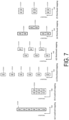
- the CCE may include REGs that are non-continuously mapped with REGs of different time periods (OFDM symbols) being mixed. As illustrated in FIG. 7(e) , the CCE may include REGs that are mapped in a distributed manner in the unit of multiple REG groups. As illustrated in FIG. 7(f) , the CCE may include REGs that are mapped in a distributed manner in the unit of multiple REG groups.
- a larger REG group means that a higher gain of the channel estimation accuracy can be obtained.
- a smaller REG group means that a larger number of REG groups are included in one PDCCH candidate.
- the larger number of REG groups in one PDCCH candidate is preferable for a transmission method (referred to as precoder rotation, precoder cycling, and the like) that obtains spatial diversity by individually applying precoders to the respective REG groups.
- the REG group in the time domain is preferable for improving the channel estimation accuracy and/or reduction in the reference signals.
- the number of REGs comprising the REG group in the time domain may be 1, 2, 3, or another value.
- the number of REGs comprising the REG group in the time domain may be given at least based on the number of OFDM symbols included in the control resource set. Additionally, the number of REGs comprising the REG group in the time domain may be the same as the number of OFDM symbols included in the control resource set.
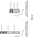
- the PDCCH candidates are mapped to two OFDM symbols, and three REG groups including two REGs are configured.
- the number of REGs comprising the REG group in the frequency domain may be either 1 or 3.
- the mapping method of the REGs comprising the CCE may be either a continuous mapping method or a noncontinuous mapping method.
- the number of REGs comprising the REG group in the frequency domain may be given at least based on the number of OFDM symbols to which one CCE is mapped.
- the number of REGs comprising the REG group in the frequency domain may be configured individually for the number of OFDM symbols to which one CCE is mapped.
- the higher layer processing unit 14 outputs uplink data (transport block) generated by a user operation or the like, to the radio transmission and/or reception unit 10.
- the higher layer processing unit 14 performs processing of a MAC layer, a Packet Data Convergence Protocol (PDCP) layer, a Radio Link Control (RLC) layer, and an RRC layer.
- PDCP Packet Data Convergence Protocol
- RLC Radio Link Control
- the radio resource control layer processing unit 36 may configure the control resource set to be associated with each (or one or more) LBT subband in the BWP for the terminal apparatus 1.
- the radio resource control layer processing unit 36 configures a frequency bandwidth and a frequency position (a number of the resource block) of the BWP.
- the radio resource control layer processing unit 36 configures the frequency bandwidth and the frequency position (the number of the resource block) of one or multiple LBT subbands.
- the base station apparatus 3 includes a communicable range (or a communication area) controlled by the base station apparatus 3.
- the communicable range is divided into one or multiple cells (or serving cells, sub-cells, beams, and the like), and communications with the terminal apparatus 1 can be managed for each cell.
- the terminal apparatus 1 selects at least one cell from the multiple cells and attempts to establish a connection with the base station apparatus 3.
- a first state in which the connection between the terminal apparatus 1 and at least one cell of the base station apparatus 3 is established is also referred to as RRC Connection.
- a second state in which the terminal apparatus 1 has not established the connection with any cell of the base station apparatus 3 is also referred to as RRC idle.
- the terminal apparatus 1 receives the PBCH transmitted from the target cell.
- the PBCH may be transmitted that includes essential information block (MIB and Essential Information Block (EIB)) including the essential system information used for the connection of the terminal apparatus 1 with the target cell.
- the essential information block is system information.
- the essential information block may include information on the radio frame number.
- the essential information block may include information on a position in a super frame including multiple radio frames (e.g., information for indicating at least some of System Frame Numbers (SFNs) in the super frame).
- the PBCH may include an index of the synchronization signal.
- the PBCH may include information on the reception of a PDCCH.
- the essential information block may be mapped to a BCH in a transport channel.
- the essential information block may be mapped to a BCCH in a logical channel.
- the terminal apparatus 1 may monitor the PDCCH based on at least the information on the reception of the PDCCH.
- the terminal apparatus 1 may monitor the PDCCH based on at least the information on the REG group.
- the terminal apparatus 1 may assume the configuration applied for monitoring the PDCCH based on at least the information on the reception of the PDCCH.
- a second implementation of the present disclosure is a communication method used in a terminal apparatus for receiving a PDCCH, the communication method including : configuring a control resource set based on RRC signaling; monitoring a plurality of PDCCH candidates in the control resource set; and decoding a PDCCH candidate of the plurality of PDCCH candidates.
- the control resource set is configured for one or more LBT subband in a bandwidth part (BWP).
- a third implementation of the present disclosure is a base station apparatus for transmitting a PDCCH, the base station apparatus including: a radio resource control layer processing unit configured to configure a control resource set for a terminal apparatus; and a transmitter configured to transmit the PDCCH by using a PDCCH candidate in the control resource set.
- the control resource set is configured for one or more LBT subband in a bandwidth part (BWP) of the terminal apparatus.
- the "computer-readable recording medium” may include a medium that dynamically retains a program for a short period of time, such as a communication line in a case that the program is transmitted over a network such as the Internet or over a communication line such as a telephone line, and may also include a medium that retains the program for a fixed period of time, such as a volatile memory included in the computer system functioning as a server or a client in such a case.
- the previously-described program may be one for realizing some of the previously-described functions, and also may be one capable of realizing the previously-described functions in combination with a program already recorded in a computer system.
- the base station apparatus 3 may be achieved as an aggregation (apparatus group) including multiple apparatuses.
- apparatus group may include some or all portions of each function or each functional block of the base station apparatus 3 according to the above-described implementations.
- the apparatus group is required to have a complete set of functions or functional blocks of the base station apparatus 3.
- the terminal apparatus 1 according to the previously-described implementations can also communicate with the multiple apparatuses of the base station apparatus.
Description
- The present disclosure relates to a terminal apparatus, a base station apparatus, and a communication method.
- In the 3rd Generation Partnership Project (3GPP), specifications of a radio access method and a radio network for cellular mobile communications (hereinafter referred to as "Long Term Evolution (LTE)" or "Evolved Universal Terrestrial Radio Access (EUTRA)") have been drafted. In LTE, a base station apparatus is also referred to as an evolved NodeB (eNodeB), and a terminal apparatus is also referred to as User Equipment (UE). LTE is a cellular communication system in which multiple areas are deployed in a cell structure, with each of the multiple areas being covered by a base station apparatus. A single base station apparatus may manage multiple cells.
- 3GPP has been studying a next generation standard (New Radio (NR)) ("New SID proposal: Study on New Radio Access Technology," RP-160671, NTT DOCOMO Inc., 3GPP TSG RAN Meeting #71, Goteborg, Sweden, 7th to 10th March, 2016.) to make a proposal for International Mobile Telecommunication (IMT)-2020, a standard for a next-generation mobile communication system, standardized by the International Telecommunication Union (ITU). NR is required to satisfy requirements for three scenarios including enhanced Mobile BroadBand (eMBB), massive Machine Type Communication (mMTC), and Ultra Reliable and Low Latency Communication (URLLC) in a single technology framework.
- Further, application of NR in a frequency band that does not require license (Unlicensed Spectrum) has been under study ("Revised SID on NR-based Access to Unlicensed Spectrum", RP-171601, Qualcomm Incorporated, 3GPP TSG RAN Meeting #77, Sapporo, Japan, 11th to 14th September, 2017). Implementation of a data rate of several Gbps by applying NR supporting a wide band of 100 MHz to a carrier of the frequency band that does not require license has been under study.
- Document MediaTek Inc., "Design of GC PDCCH", 3GPP TSG RAN WG1 Meeting AH_NR#3, Nagoya, Japan, 18 to 21 September 2017, 3GPP Draft R1-1716200, discusses the design for GC PDCCH including physical structure, contents, and UE behavior.
- Document Huawei et al, "Remaining issues on bandwidth part and wideband operation", 3GPP TSG RAN WG1 NR Ad Hoc Meeting, Vancouver, Canada, 22 to 26 January, 2018, 3GPP Draft R1- 1800018, discusses issues on bandwidth part and scenarios of multiple active BWP.
- In some countries around the world, Listen-Before-Talk (LBT) needs to be applied to frequency bands that do not require license. LBT refers to a mechanism in which carrier sensing is performed before transmission is started, and only in a case that it is confirmed that resources (channels) are not used in other neighboring systems as a result of the carrier sensing, transmission within a prescribed time length is enabled.
- One implementation of the present disclosure implements application of LBT in frequency bands that do not require license and application of NR at the same time. One implementation of the present disclosure provides a terminal apparatus capable of efficiently performing wideband communication, a communication method used in the terminal apparatus, a base station apparatus capable of efficiently performing wideband communication, and a communication method used in the base station apparatus.
- The above and other objects are achieved by a terminal apparatus, a communication method performed by a terminal apparatus, a base station apparatus and a communication method performed by a base station apparatus as defined in the independent claims respectively. Preferred embodiments are set forth in the dependent claims.
- According to one implementation of the present disclosure, the terminal apparatus can efficiently perform wideband communication. In addition, the base station apparatus can efficiently perform wideband communication.
-
-
FIG. 1 is a conceptual diagram of a radio communication system according to one implementation of the present disclosure. -
FIG. 2 is an example illustrating a configuration of a radio frame, subframes, and slots according to one implementation of the present disclosure. -
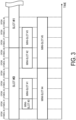
FIG. 3 is a diagram illustrating a configuration of the slots and mini-slots according to one implementation of the present disclosure. -
FIG. 4 is a diagram illustrating an example of mapping control resource sets according to one implementation of the present disclosure. -
FIG. 5 is a diagram illustrating an example of resource elements included in the slot according to one implementation of the present disclosure. -
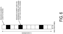
FIG. 6 is a diagram illustrating an example of a configuration of one resource element group (REG) according to one implementation of the present disclosure. -
FIG. 7 is a diagram illustrating a configuration of control channel elements (CCEs) according to one implementation of the present disclosure. -
FIG. 8 is a diagram illustrating an example of a relationship between the number of REGs comprising a REG group and a mapping method of the PDCCH candidate according to one implementation of the present disclosure. -
FIG. 9 is a diagram illustrating an example of the mapping of the REGs comprising the CCE according to one implementation of the present disclosure. -
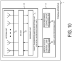
FIG. 10 is a schematic block diagram illustrating a configuration of aterminal apparatus 1 according to one implementation of the present disclosure. -
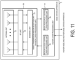
FIG. 11 is a schematic block diagram illustrating a configuration of abase station apparatus 3 according to one implementation of the present disclosure. -
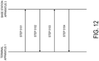
FIG. 12 is a diagram illustrating an example of a first initial connection procedure (4-step contention based random access channel (RACH) procedure) according to one implementation of the present disclosure. -
FIG. 13 is a diagram illustrating an example of the PDCCH candidates monitored by theterminal apparatus 1 according to one implementation of the present disclosure. -
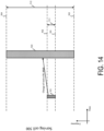
FIG. 14 is a diagram illustrating an example of Bandwidth adaptation according to one implementation of the present disclosure. -
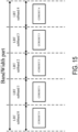
FIG. 15 is a diagram illustrating an example of a configuration of the control resource set of each LBT subband according to the one implementation of the present disclosure. - Embodiments of the present disclosure will be described below.
-
FIG. 1 is a conceptual diagram of a radio communication system according to one implementation of the present disclosure. InFIG. 1 , the radio communication system includes terminal apparatuses 1A to 1C and a base station apparatus 3 (Next Generation NodeB(gNB)). Hereinafter, the terminal apparatuses 1A to 1C are each also referred to as aterminal apparatus 1 or user equipment (UE). - Hereinafter, various radio parameters related to communications between the
terminal apparatus 1 and thebase station apparatus 3 will be described. Here, at least some of the radio parameters (for example, Subcarrier Spacing (SCS)) are also referred to as Numerology. The radio parameters include at least some of the subcarrier spacing, a length of an Orthogonal Frequency Division Multiplexing (OFDM) symbol, a length of a subframe, a length of a slot, or a length of a mini-slot. - The subcarrier spacing used for the radio communications is one of the radio parameters for the communication method (for example, OFDM, Orthogonal Frequency Division Multiple Access (OFDMA), Single Carrier-Frequency Division Multiple Access (SC-FDMA), Discrete Fourier Transform-spread-OFDM (DFT-s-OFDM) used for radio communication between the
terminal apparatus 1 and thebase station apparatus 3. For example, the subcarrier spacing is 15 kHz, 30 kHz, 60 kHz, or 120 kHz. -
FIG. 2 is an example illustrating a configuration of a radio frame, subframes, and slots according to one implementation of the present disclosure. In the example illustrated inFIG. 2 , a length of each slot is 0.5 ms, a length of each subframe is 1 ms, and a length of the radio frame is 10 ms. The slot may be a unit of resource allocation in the time domain. For example, the slot may be a unit for mapping of one transport block. For example, the transport block may be mapped to one slot. Here, the transport block may be a unit of data to be transmitted in a prescribed interval (for example, Transmission Time Interval (TTI)) defined in a higher layer (for example, Medium Access Control (MAC) or RRC (Radio Resource Control)). - For example, the length of the slot may be given according to the number of OFDM symbols. For example, the number of OFDM symbols may be 7 or 14. The length of the slot may be given based on at least a length of an OFDM symbol. The length of the OFDM symbol may differ based on at least the subcarrier spacing. The length of the OFDM symbol may be given based on at least the number of points of Fast Fourier Transform (FFT) used to generate the OFDM symbol. The length of the OFDM symbol may include a length of a Cyclic Prefix (CP) added to the OFDM symbol. Here, the OFDM symbol may be called a symbol. In addition, in a case that a communication scheme other than OFDM is used in communication between the
terminal apparatus 1 and the base station apparatus 3 (e.g., in a case that SC-FDMA or DFT-s-OFDM is used, etc.), a SC-FDMA symbol and/or a DFT-s-OFDM symbol to be generated is also referred to as an OFDM symbol. Moreover, unless otherwise stated, OFDM includes SC-FDMA or DFT-s-OFDM. - For example, the length of a slot may be 0.125 ms, 0.25 ms, 0.5 ms, or 1 ms. For example, in a case that the subcarrier spacing is 15 kHz, the length of the slot may be 1 ms. For example, in a case that the subcarrier spacing is 30 kHz, the length of the slot may be 0.5 ms. For example, in a case that the subcarrier spacing is 120 kHz, the length of the slot may be 0.125 ms. For example, in a case that the subcarrier spacing is 15 kHz, the length of the slot may be 1 ms. For example, in a case that the length of the slot is 0.125 ms, one subframe may include eight slots. For example, in a case that the length of the slot is 0.25 ms, one subframe may include four slots. For example, in a case that the length of the slot is 0.5 ms, one subframe may include two slots. For example, in a case that the length of the slot is 1 ms, one subframe may include one slot.
- The OFDM includes a multi-carrier communication scheme in which waveform shaping (Pulse Shape), Peak-to-Average power Ratio (PAPR) reduction, out-of-band radiation reduction, or filtering, and/or phase processing (e.g., phase rotation, etc.) are applied. The multi-carrier communication scheme may be a communication scheme for generating/transmitting a signal in which multiple subcarriers are multiplexed.
- The radio frame may be given according to the number of subframes. The number of subframes for the radio frame may be, for example, 10. The radio frame may be given according to the number of slots.
-
FIG. 3 is a diagram illustrating a configuration example of the slots and mini-slots according to the one implementation of the present disclosure. InFIG. 3 , the number of OFDM symbols comprising a single slot is seven. The mini-slot may include one or more OFDM symbols less than the number of multiple OFDM symbols comprising the slot. The length of the mini-slot may be shorter than that of the slot.FIG. 3 illustrates amini-slot # 0 to amini-slot # 5 as an example of the configuration of the mini-slots. The mini-slot may include a single OFDM symbol, as indicated by themini-slot # 0. The mini-slot may include two OFDM symbols as indicated by themini-slots # 1 to #3. Moreover, a gap (time interval) may be inserted between two mini-slots, as indicated by themini-slots # 1 and #2. Moreover, the mini-slot may be configured so as to cross the boundary between theslots # 0 and #1, as indicated by themini-slot # 5. In other words, the mini-slot may be configured so as to cross the boundary between the slots. Here, the mini-slot is also referred to as a sub-slot. The mini-slot is also referred to as short TTI (sTTI). Moreover, in the following, the slot may be replaced by the mini-slot. The mini-slot may include the same number of OFDM symbols as that of the slot. The mini-slot may include OFDM symbols more than the number of multiple OFDM symbols comprising the slot. The length of the time domain of the mini-slot may be shorter than the length of the slot. The length of the time domain of the mini-slot may be shorter than the length of the subframe. - A physical channel and a physical signal according to various implementations of the present disclosure will be described below.
- In
FIG. 1 , at least the following uplink physical channels are used for uplink radio communication from theterminal apparatus 1 to thebase station apparatus 3. The uplink physical channels are used by a physical layer for transmission and/or reception of information output from a higher layer. - Physical Uplink Control Channel (PUCCH)
- Physical Uplink Shared Channel (PUSCH)
- Physical Random Access Channel (PRACH)
- The PUCCH is used to transmit and/or receive Uplink Control Information (UCI). The uplink control information includes Channel State Information (CSI) of downlink channel, a Scheduling Request (SR) used to request a PUSCH (Uplink-Shared Channel (UL-SCH)) resource for initial transmission, and a Hybrid Automatic Repeat Request Acknowledgement (HARQ-ACK) for downlink data (Transport block (TB), MAC Protocol Data Unit (MAC PDU), Downlink-Shared Channel (DL-SCH), and Physical Downlink Shared Channel (PDSCH)). The HARQ-ACK indicates an acknowledgement (ACK) or a negative-acknowledgement (NACK). The HARQ-ACK is also referred to as HARQ feedback, HARQ information, HARQ control information, and an ACK/NACK.
- The CSI includes at least a Channel Quality Indicator (CQI). The channel state information may include a Rank Indicator (RI). The channel state information may include a Precoder Matrix Indicator (PMI). The CQI is an indicator associated with channel quality (propagation strength), and the PMI is an indicator indicating a precoder. The RI is an indicator indicating a transmission rank (or the number of transmission layers).
- The PUSCH is used to transmit and/or receive uplink data (TB, MAC PDU, UL-SCH, and PUSCH). The PUSCH may be used to transmit and/or receive a HARQ-ACK and/or channel state information along with the uplink data. Further, the PUSCH may be used to transmit and/or receive only the channel state information or only the HARQ-ACK and the channel state information. The PUSCH is used to transmit and/or receive a
random access message 3. - The PRACH may be used to transmit and/or receive a random access preamble (random access message 1). The PRACH is used to indicate an initial connection establishment procedure, a handover procedure, a connection re-establishment procedure, synchronization (timing adjustment) for uplink data transmission, and a request for a PUSCH (UL-SCH) resource. The random access preamble may be used to notify the
base station apparatus 3 of an index (random access preamble index) given by a higher layer of theterminal apparatus 1. - The random access preamble may be given by cyclic-shifting a Zadoff-Chu sequence corresponding to a physical root sequence index u. The Zadoff-Chu sequence may be generated based on the physical root sequence index u. In a single cell, multiple random access preambles may be defined. A random access preamble may be identified at least based on an index of the random access preamble. A different random access preamble corresponding to a different index of the random access preamble may correspond to a different combination of the physical root sequence index u and the cyclic shift. The physical root sequence index u and the cyclic shift may be given at least based on information included in system information. The physical root sequence index u may be an index for identifying a sequence included in the random access preamble. The random access preamble may be identified at least based on the physical root sequence index u.
- In
FIG. 1 , the following uplink physical signals are used for uplink radio communication. The uplink physical signals may not be used for transmitting and/or receiving information output from a higher layer, but is used by the physical layer.
Uplink Reference Signal (UL RS) - According to the present disclosure, at least the following two types of uplink reference signal may be used.
- Demodulation Reference Signal (DMRS)
- Sounding Reference Signal (SRS)
- The DMRS is associated with transmission and/or reception of a PUSCH and/or a PUCCH. The DMRS is multiplexed with the PUSCH or the PUCCH. The
base station apparatus 3 uses the DMRS in order to perform channel compensation of the PUSCH or the PUCCH. Transmission of both of the PUSCH and the DMRS is hereinafter referred to simply as transmission of the PUSCH. Transmission of both of the PUCCH and the DMRS is hereinafter referred to simply as transmission of the PUCCH. Reception of both of the PUSCH and the DMRS is hereinafter referred to simply as reception of the PUSCH. Reception of both of the PUCCH and the DMRS is hereinafter referred to simply as reception of the PUCCH. - The SRS may not be associated with transmission and/or reception of the PUSCH or the PUCCH. The
base station apparatus 3 may use the SRS for measuring a channel state. The SRS may be transmitted and/or received at the end of a subframe in an uplink slot or in a prescribed number of OFDM symbols from the end. - In
FIG. 1 , the following downlink physical channels are used for downlink radio communication from thebase station apparatus 3 to theterminal apparatus 1. The downlink physical channels are used by the physical layer for transmission and/or reception of information output from a higher layer. - Physical Broadcast Channel (PBCH)
- PDCCH
- PDSCH
- The PBCH is used for broadcasting a Master Information Block (MIB or Broadcast Channel (BCH)) that is commonly used by the
terminal apparatuses 1. The PBCH may be transmitted at a prescribed transmission interval. For example, the PBCH may be transmitted at an interval of 80 ms. Contents of information included in the PBCH may be updated at every 80 ms. The PBCH may include 288 subcarriers. The PBCH may include two, three, or four OFDM symbols. The MIB may include information related to an identifier (index) that is related to a synchronization signal. The MIB may include information indicating at least some of numbers of a slot, a subframe, and a radio frame in which a PBCH is transmitted. - The PDCCH (NR PDCCH) is used to transmit and/or receive Downlink Control Information (DCI). The downlink control information is also called a DCI format. The downlink control information may include at least either a downlink grant or an uplink grant. The downlink grant is also referred to as downlink assignment or downlink allocation. The downlink control information may include Unlicensed access common information. The Unlicensed access common information is control information related to access, transmission and/or reception, or the like in the frequency band that does not require license. The Unlicensed access common information may be information of a downlink subframe configuration (Subframe configuration for Unlicensed Access). The downlink subframe configuration indicates positions of the OFDM symbols occupied in the subframe to which the PDCCH including information of the downlink subframe configuration is mapped and/or positions of the OFDM symbol occupied in the subframe next to the subframe to which the PDCCH including the information of the downlink subframe configuration is mapped. In the occupied OFDM symbols, transmission and/or reception of a downlink physical channel and a downlink physical signal is performed. The Unlicensed access common information may be information of an uplink subframe configuration (UL duration and offset). The uplink subframe configuration indicates a position of a subframe at which an uplink subframe is started with a reference subframe being a subframe to which the PDCCH including information of the uplink subframe configuration is mapped, and the number of subframes of the uplink subframes. The
terminal apparatus 1 is not required to receive a downlink physical channel and a downlink physical signal in the subframe indicated by the information of the uplink subframe configuration. - For example, the downlink control information including the downlink grant or the uplink grant is transmitted and/or received in the PDCCH by including a Cell-Radio Network Temporary Identifier (C-RNTI). For example, the Unlicensed access common information is transmitted and/or received in the PDCCH by including a Common Control-Radio Network Temporary Identifier (CC-RNTI).
- A single downlink grant is at least used for scheduling of a single PDSCH in a single serving cell. The downlink grant is at least used for the scheduling of the PDSCH in the same slot as the slot in which the downlink grant is transmitted. The downlink grant may be used for scheduling of the PDSCH within a different slot from the slot in which the downlink grant has been transmitted.
- A single uplink grant is at least used for scheduling of a single PUSCH in a single serving cell.
- In the
terminal apparatus 1, one or multiple control resource sets (CORESETs) may be configured to search for a PDCCH. Theterminal apparatus 1 may attempt to receive or detect the PDCCH in the configured control resource set. Details of the control resource set will be described later. - The PDSCH is used to transmit and/or receive downlink data (DL-SCH, PDSCH). The PDSCH is at least used to transmit and/or receive a random access message 2 (random access response). The PDSCH is at least used to transmit and/or receive system information including parameters used for initial access.
- In
FIG. 1 , the following downlink physical signals are used for the downlink radio communication. The downlink physical signals may not be used for transmitting and/or receiving information output from a higher layer, but is used by the physical layer. - Synchronization signal (SS)
- Downlink Reference Signal (DL RS)
- The synchronization signal is used for the
terminal apparatus 1 to establish synchronization in a frequency domain and a time domain in the downlink. The synchronization signal includes a Primary Synchronization Signal (PSS) and a Secondary Synchronization Signal (SSS). - The downlink reference signal is used for the
terminal apparatus 1 to perform channel compensation on a downlink physical channel. The downlink reference signal is used for theterminal apparatus 1 to obtain the downlink channel state information. - According to the present disclosure, at least the following type of downlink reference signal is used.
DMRS - The DMRS corresponds to transmission and/or reception of the PDCCH and/or the PDSCH. The DMRS is multiplexed with the PDCCH or the PDSCH. The
terminal apparatuses 1 may use the DMRS corresponding to the PDCCH or the PDSCH in order to perform channel compensation of the PDCCH or the PDSCH. Hereinafter, transmission of both of the PDCCH and the DMRS corresponding to the PDCCH is simply referred to as transmission of the PDCCH. Hereinafter, transmission and/or reception of both of the PDCCH and the DMRS corresponding to the PDCCH is simply referred to as transmission and/or reception of the PDCCH. Hereinafter, transmission of both of the PDSCH and the DMRS corresponding to the PDSCH is simply referred to as transmission of the PDSCH. Hereinafter, reception of both of the PDSCH and the DMRS corresponding to the PDSCH is simply referred to as reception of the PDSCH. - The DMRS may be an RS individually configured for the
terminal apparatus 1. The sequence of the DMRS may be given at least based on parameters individually configured for theterminal apparatus 1. The DMRS may be individually transmitted for the PDCCH and/or the PDSCH. The DMRS may be an RS configured common to the multipleterminal apparatuses 1. The sequence of the DMRS may be given regardless of the parameter individually configured for theterminal apparatus 1. For example, the sequence of the DMRS may be given based on at least some of a slot number, a mini-slot number, and a cell identity (ID). The DMRS may be an RS to be transmitted regardless of whether the PDCCH and/or the PDSCH has been transmitted. - Downlink physical channels and downlink physical signals are collectively referred to as downlink signals. Uplink physical channels and uplink physical signals are collectively referred to as uplink signals. The downlink physical channels and the uplink physical channels are collectively referred to as physical channels. The downlink physical signals and the uplink physical signals are collectively referred to as physical signals.
- The BCH, the UL-SCH, and the DL-SCH are transport channels. A channel used in a MAC layer is referred to as a transport channel. A unit of the transport channel used in the MAC layer is also referred to as a transport block or a MAC PDU. A HARQ is controlled for each transport block in the MAC layer. The transport block is a unit of data that the MAC layer delivers to the physical layer. In the physical layer, the transport block is mapped to a codeword, and a modulation process is performed for each codeword.
- The
base station apparatus 3 and theterminal apparatus 1 may exchange (transmit and/or receive) a signal in the higher layer. For example, thebase station apparatus 3 and theterminal apparatus 1 may transmit and/or receive Radio Resource Control (RRC) signaling (also referred to as a Radio Resource Control (RRC) message or Radio Resource Control (RRC) information) in an RRC layer. Furthermore, thebase station apparatus 3 and theterminal apparatus 1 may transmit and/or receive, in the MAC layer, a MAC Control Element (CE). Here, the RRC signaling and/or the MAC CE is also referred to as higher layer signaling. - The PUSCH and the PDSCH are at least used to transmit and/or receive the RRC signaling and the MAC CE. Here, the RRC signaling transmitted from the
base station apparatus 3 through the PDSCH may be signaling common to the multipleterminal apparatuses 1 in a cell. The signaling common to the multipleterminal apparatuses 1 in the cell is also referred to as common RRC signaling. The RRC signaling transmitted from thebase station apparatus 3 through the PDSCH may be signaling dedicated to a certain terminal apparatus 1 (also referred to as dedicated signaling or UE specific signaling). The signaling dedicated to theterminal apparatus 1 is also referred to as dedicated RRC signaling. A cell-specific parameter may be transmitted by using the signaling common to the multipleterminal apparatuses 1 in the cell or the signaling dedicated to the certainterminal apparatus 1. A UE-specific parameter may be transmitted by using the signaling dedicated to the certainterminal apparatus 1. The PDSCH including the dedicated RRC signaling may be scheduled via the PDCCH in the control resource set. The PDSCH including the common RRC signaling may be scheduled via the PDCCH in the control resource set. - A Broadcast Control CHannel (BCCH), a Common Control CHannel (CCCH), and a Dedicated Control Channel (DCCH) are logical channels. For example, the BCCH is a higher layer channel used to transmit the MIB. Furthermore, the CCCH is a higher layer channel used to transmit and/or receive information common to the multiple
terminal apparatuses 1. Here, the CCCH is used for aterminal apparatus 1 that is not in an RRC connected state, for example. Furthermore, the DCCH is a channel of the higher layer used to transmit and/or receive individual control information (dedicated control information) to theterminal apparatus 1. Here, the DCCH is used for aterminal apparatus 1 that is in the RRC connected state, for example. - The BCCH in the logical channel may be mapped to the BCH, the DL-SCH, or the UL-SCH in the transport channel. The CCCH in the logical channel may be mapped to the DL-SCH or the UL-SCH in the transport channel. The DCCH in the logical channel may be mapped to the DL-SCH or the UL-SCH in the transport channel.
- The UL-SCH in the transport channel is mapped to the PUSCH in the physical channel. The DL-SCH in the transport channel is mapped to the PDSCH in the physical channel. The BCH in the transport channel is mapped to the PBCH in the physical channel.
- Hereinafter, the control resource set will be described.
-
FIG. 4 is a diagram illustrating an example of mapping of control resource sets according to the one implementation of the present disclosure. The control resource set may be a time frequency domain in which one or multiple control channels may be mapped. The control resource set may be a region in which theterminal apparatus 1 attempts to receive and/or detect (perform blind detection of (perform blind decoding (BD) of)) the PDCCH. As illustrated inFIG. 4(a) , the control resource set may include continuous resources (Localized resource) in the frequency domain. Further, as illustrated inFIG. 4(b) , the control resource set may include noncontinuous resources (distributed resources) in the frequency domain. - In the frequency domain, the unit of mapping the control resource set may be a resource block. The control resource set may include multiple resource blocks. In the time domain, the unit of mapping the control resource set may be an OFDM symbol. The control resource set may include one, two, or three OFDM symbols.
- The frequency domain of the control resource set may be identical to the system bandwidth of a serving cell. In addition, the frequency domain of the control resource set may be given at least based on the system bandwidth of the serving cell. The frequency domain of the control resource set may be given at least based on higher layer signaling or system information. For example, the position of each resource block comprising the control resource set is reported from the
base station apparatus 3 to theterminal apparatus 1 by using higher layer signaling. For a control resource set, the position of each resource block comprising the control resource set is reported from thebase station apparatus 3 to theterminal apparatus 1 by using higher layer signaling. - The time domain of the control resource set may be given at least based on higher layer signaling or system information. For example, the number of OFDM symbols comprising the control resource set is reported from the
base station apparatus 3 to theterminal apparatus 1 by using higher layer signaling. For example, the start position of the OFDM symbol comprising the control resource set is reported from thebase station apparatus 3 to theterminal apparatus 1 by using higher layer signaling. For example, the end position of the OFDM symbol comprising the control resource set is reported from thebase station apparatus 3 to theterminal apparatus 1 by using higher layer signaling. For example, the position of the subframe at which the control resource set is mapped is reported from thebase station apparatus 3 to theterminal apparatus 1 by using higher layer signaling. For example, the position of the slot at which the control resource set is mapped is reported from thebase station apparatus 3 to theterminal apparatus 1 by using higher layer signaling. For example, periodicity of the subframe to which the control resource set is mapped is reported from thebase station apparatus 3 to theterminal apparatus 1 by using higher layer signaling. For example, periodicity of the slot to which the control resource set is mapped is reported from thebase station apparatus 3 to theterminal apparatus 1 by using higher layer signaling. - For the control resource set, one of or both of types of a Common control resource set (Common CORESET) and a Dedicated control resource set (UE specific CORESET) may be used. The common control resource set may be a control resource set configured commonly to multiple
terminal apparatuses 1. The common control resource set may be given at least based on a synchronization signal, an MIB, first system information, second system information, common RRC signaling, dedicated RRC signaling, a cell ID, or the like. For example, the position of the subframe at which the common control resource set is mapped may be given at least based on a synchronization signal, an MIB, common RRC signaling, or the like. The dedicated control resource set may be a control resource set configured to be dedicatedly used for each individualterminal apparatus 1. The dedicated control resource set may be given at least based on dedicated RRC signaling and/or a value of a C-RNTI. - The control resource set may be a set of control channels (or control channel candidates) to be monitored by the
terminal apparatus 1. The control resource set may include a set of control channels (or control channel candidates) to be monitored by theterminal apparatus 1. The control resource set may include one or multiple Search Spaces (SSs). - The search space includes one or multiple PDCCH candidates. The
terminal apparatus 1 receives a PDCCH candidate included in the search space and attempts to receive a PDCCH. Here, the PDCCH candidate may also be referred to as a blind detection candidate. - The search space includes two types, that is, a Common Search Space (CSS) and a UE-specific Search Space (USS). The CSS may be a search space configured commonly to multiple
terminal apparatuses 1. The USS may be a search space including a configuration to be dedicatedly used for each individualterminal apparatus 1. The CSS may be given at least based on a synchronization signal, an MIB, first system information, second system information, common RRC signaling, dedicated RRC signaling, a cell ID, or the like. The USS may be given at least based on dedicated RRC signaling and/or a value of a C-RNTI. - For the CSS, a
type 0 PDCCH CSS for a DCI format that is scrambled with a System Information-RNTI (SI-RNTI) used for transmission of system information in a primary cell and a type1-PDCCH CSS for a DCI format that is scrambled with an Interruption-RNTI (INT-RNTI) used for initial access in the primary cell may be used. For the CSS, a PDCCH CSS of a type for a DCI format that is scrambled with a CC-RNTI used for Unlicensed access may be used. Theterminal apparatus 1 can monitor PDCCH candidates in those search spaces. The DCI format that is scrambled with a prescribed RNTI may be a DCI format to which a Cyclic Redundancy Check (CRC) scrambled with the prescribed RNTI is added. - Note that the PDCCH and/or the DCI included in the CSS need not include a Carrier Indicator Field (CIF) that indicates correspondence between the PDCCH/DCI and its scheduling target of the PDSCH or the PUSCH for a certain serving cell (or a certain component carrier).
- Note that, in a case that carrier aggregation in which multiple serving cells and/or multiple component carriers are aggregated to perform communication (transmission and/or reception) with the
terminal apparatus 1 is configured, the PDCCH and/or the DCI included in the USS for a prescribed serving cell (prescribed component carrier) includes the CIF that indicates correspondence between the PDCCH/DCI and its scheduling target of the PDSCH or the PUSCH for a certain serving cell and/or a certain component carrier. - Note that, in a case that communication is performed by using a single serving cell and/or a single component carrier for the
terminal apparatus 1, the PDCCH and/or the DCI included in the USS need not include the CIF that indicates correspondence between the PDCCH/DCI and its scheduling target of the PDSCH or the PUSCH for a certain serving cell and/or a certain component carrier. - The common control resource set may include the CSS. The common control resource set may include both of the CSS and the USS. The dedicated control resource set may include the USS. The dedicated control resource set may include the CSS.
- In the common control resource set, the PDCCH including control information necessary for Unlicensed access (Unlicensed access common information) may be transmitted and/or received. In the common control resource set, the PDCCH including resource allocation information of the PDSCH including Remaining Minimum System Information (RMSI) may be transmitted and/or received. In the common control resource set, the PDCCH including resource allocation information of the PDSCH including a Random Access Response (RAR) may be transmitted and/or received. In the common control resource set, the PDCCH including control information indicating Pre-emption resources may be transmitted and/or received. In the common control resource set, the PDCCH including control information indicating a slot format indicator may be transmitted and/or received. Note that multiple common control resource sets may be configured, and each of the common control resource sets may be mapped to a different subframe. Note that multiple common control resource sets may be configured, and each of the common control resource sets may be mapped to the same subframe. Note that multiple common control resource sets may be configured, and a different PDCCH or different control information may be mapped to each of the common control resource sets.
- Multiple dedicated control resource sets may be configured in a subframe or in a slot. Multiple dedicated control resource sets may be configured, and each of the dedicated control resource sets may be mapped to the same subframe or the same slot. Multiple dedicated control resource sets may be configured, and each of the dedicated control resource sets may be mapped to a different subframe or a different slot.
- A physical resource of the search space includes a control channel element (CCE) of the control channel. The CCE includes a prescribed number of REGs. For example, the CCE may include six REGs. An REG may include a single OFDM symbol of a single Physical Resource Block (PRB). In other words, the REG may include 12 Resource Elements (REs). The PRB is also simply referred to as a Resource Block (RB).
- In other words, the
terminal apparatus 1 can detect the PDCCH and/or the DCI for theterminal apparatus 1 by performing blind detection of the PDCCH candidates included in the search space in the control resource set. - The number of times of the blind detection to be performed on a single control resource set in a single serving cell and/or a single component carrier may be determined based on a type of the search space, a type of an aggregation level, or the number of PDCCH candidates for the PDCCH included in the control resource set. Here, the type of the search space may include at least one of a CSS and/or a USS and/or a UE Group SS (UGSS) and/or a Group CSS (GCSS). The type of the aggregation level may indicate a maximum aggregation level supported for the CCE comprising the search space, and may be defined/configured based on at least one of {1, 2, 4, 8, ..., X} (X is a prescribed value). The number of PDCCH candidates may indicate the number of PDCCH candidates for a certain aggregation level. In other words, the number of PDCCH candidates may be defined/configured for each of multiple aggregation levels. Note that the UGSS may be a search space assigned commonly to one or multiple
terminal apparatuses 1. The GCSS may be a search space in which DCI including a parameter related to the CSS is mapped to one or multipleterminal apparatuses 1. Note that the aggregation level indicates an aggregation level of a prescribed number of CCEs, and relates to a total number of CCEs comprising a single PDCCH and/or search space. - Note that the value of the aggregation level may be associated with coverage corresponding to the PDCCH and/or the search space or the size of the DCI (DCI format size, payload size) included in the PDCCH and/or the search space.
- Note that, in a case that the start position (start symbol) of the PDCCH symbol is configured for a single control resource set and more than one PDCCH can be detected in the control resource set in a prescribed period, each of the type of the search space, the type of the aggregation level, and the number of PDCCH candidates for the PDCCH included in the control resource set may be configured for the time domain corresponding to each start symbol. Each of the type of the search space, the type of the aggregation level, and the number of PDCCH candidates for the PDCCH included in the control resource set may be configured for each control resource set, may be provided/configured by using DCI and/or higher layer signaling, or may be defined/configured in a specification in advance. Note that the number of PDCCH candidates may be the number of PDCCH candidates in a prescribed period. Note that the prescribed period may be 1 ms. The prescribed period may be 1 microsecond. Alternatively, the prescribed period may be a period of one slot. Alternatively, the prescribed period may be a period of one OFDM symbol.
- Note that, in a case that there is more than one start position (start symbol) of the PDCCH symbol for a single control resource set, that is, there are multiple timings for performing blind detection (monitoring) of the PDCCH in a prescribed period, each of the type of the search space, the type of the aggregation level, and the number of PDCCH candidates for the PDCCH included in the control resource set may be configured for the time domain corresponding to each start symbol. Each of the type of the search space, the type of the aggregation level, and the number of PDCCH candidates for the PDCCH included in the control resource set may be configured for each control resource set, may be provided/configured by using DCI and/or higher layer signaling, or may be defined/configured in a specification (in advance).
- Note that, as a configuration used to indicate the number of PDCCH candidates, the number to be reduced from a prescribed number of PDCCH candidates may be defined/configured for each aggregation level.
- The
terminal apparatus 1 may transmit/report capability information related to blind detection to thebase station apparatus 3. Theterminal apparatus 1 may transmit/report the number of PDCCH candidates that can be processed in a single subframe to thebase station apparatus 3 as capability information related to the PDCCH. In a case that a larger number of control resource sets than a prescribed number can be configured for one or multiple serving cells/component carriers, theterminal apparatus 1 may transmit/report the capability information related to blind detection to thebase station apparatus 3. - In a case that the
terminal apparatus 1 supports a first slot format and a second slot format, theterminal apparatus 1 may transmit/report capability information related to the slot format to thebase station apparatus 3. - In a case that a larger number of control resource sets than a prescribed number can be configured for one or multiple serving cells/component carriers, the
terminal apparatus 1 may transmit/report the capability information related to blind detection to thebase station apparatus 3. - Note that the capability information related to blind detection may include information indicating a maximum number of times of the blind detection in a prescribed period. Further, the capability information related to blind detection may include information indicating that the number of PDCCH candidates can be reduced. Further, the capability information related to blind detection may include information indicating a maximum number of control resource sets that can be subjected to the blind detection in a prescribed period. The maximum number of control resource sets and the maximum number of serving cells and/or component carriers in which the PDCCH can be monitored may each be configured as an individual parameter, or may be configured as a common parameter. Further, the capability information related to blind detection may include information indicating a maximum number of control resource sets that can be simultaneously subjected to the blind detection in a prescribed period.
- In a case that the
terminal apparatus 1 does not support detecting (performing blind detection of) a larger number of control resource sets than a prescribed number in a prescribed period, theterminal apparatus 1 need not transmit/report the capability information related to blind detection. In a case that thebase station apparatus 3 does not receive the capability information related to blind detection, thebase station apparatus 3 may transmit the PDCCH by implementing a configuration related to the control resource set so that the number of control resource sets do not exceed a prescribed number for the blind detection. - The configuration related to the control resource set may include a parameter indicating a start position (start symbol) of the PDCCH. Further, the configuration related to the control resource set may include a parameter indicating a time resource region of the control resource set (the number of OFDM symbols comprising the control resource set, the position of the subframe in which the control resource set is mapped). Further, the configuration related to the control resource set may include a parameter indicating a frequency resource region of the control resource set (the number of resource blocks comprising the control resource set). Further, the configuration related to the control resource set may include a parameter indicating a type of mapping from the CCE to the REG. Further, the configuration related to the control resource set may include a REG bundle size. Further, the configuration related to the control resource set may include a parameter indicating a CCE aggregation level of the USS. Further, the configuration related to the control resource set may include a parameter indicating periodicity for monitoring the PDCCH and/or the control resource set (periodicity of the subframe, the start position of the subframe). The maximum number of blind detections of the PDCCH may be individually configured according to the start position of the PDCCH.
- The unit of the physical resource according to the present disclosure will be described below.
-
FIG. 5 is a diagram illustrating an example of resource elements included in the slot according to the one implementation of the present disclosure. Here, the resource element is a resource defined by one OFDM symbol and one subcarrier. As illustrated inFIG. 5 , the slot includes Nsymb pieces of OFDM symbols. The number of subcarriers included in the slot may be given by a product of the number NRB of resource blocks included in the slot and the number NRB SC of subcarriers per resource block. Here, the resource block is a group of the resource elements in the time domain and the frequency domain. The resource block may be used as a unit of resource allocation in the time domain and/or the frequency domain. For example, the NRB SC may be 12. The Nsymb may be the same as the number of OFDM symbols included in the subframe. The Nsymb may be the same as the number of OFDM symbols included in the slot. The NRB may be given based on a bandwidth of a cell and a subcarrier spacing. The NRB may be given based on higher layer signaling (for example, RRC signaling) transmitted from thebase station apparatus 3, and the like. Additionally, the NRB may be given based on the description in the specifications, and the like. The resource element is identified by an index k for the subcarrier and an index l for the OFDM symbol. -
FIG. 6 is a diagram illustrating an example of a configuration of one REG according to the one implementation of the present disclosure. The REG may include one OFDM symbol in one PRB. That is, the REG may include 12 continuous REs in the frequency domain. Some of multiple REs comprising the REG may be an RE to which the downlink control information is not mapped. The REG may include the RE to which the downlink control information is not mapped or need not include the RE to which the downlink control information is not mapped. The RE to which the downlink control information is not mapped may be an RE to which the reference signal is mapped, may be an RE to which a channel other than the control channel is mapped, or may be an RE which theterminal apparatus 1 assumes to have no control channel mapped. -
FIG. 7 is a diagram illustrating a configuration of CCEs according to the one implementation of the present disclosure. The CCE may include six REGs. As illustrated inFIG. 7(a) , the CCE may include REGs that are mapped continuously (such a manner of mapping may be referred to as Localized mapping) (such a manner of mapping may be referred to as non-interleaved CCE-to-REG mapping) (such a manner of mapping may be referred to as non-interleaved mapping). Note that not necessarily all of the REGs comprising the CCE need to be continuous in the frequency domain. For example, in a case that none of multiple resource blocks comprising the control resource set is continuous in the frequency domain and numbers assigned to the REGs are continuous, each of the resource blocks comprising each of the REGs assigned such continuous numbers is not continuous in the frequency domain. In a case that the control resource set includes multiple OFDM symbols and multiple REGs comprising a single CCE are mapped to multiple time periods (OFDM symbols), as illustrated inFIG. 7(b) , the CCE may include a REG group that is mapped continuously. As illustrated inFIG. 7(c) , the CCE may include REGs that are mapped non-continuously (such a manner of mapping may be referred to as Distributed mapping) (such a manner of mapping may be referred to as interleaved CCE-to-REG mapping) (such a manner of mapping may be referred to as interleaved mapping). The REGs comprising the CCE by using an interleaver may be non-continuously mapped to resources in the time frequency domain. In a case that the control resource set includes multiple OFDM symbols and multiple REGs comprising a single CCE are mapped to multiple time periods (OFDM symbols), as illustrated inFIG. 7(d) , the CCE may include REGs that are non-continuously mapped with REGs of different time periods (OFDM symbols) being mixed. As illustrated inFIG. 7(e) , the CCE may include REGs that are mapped in a distributed manner in the unit of multiple REG groups. As illustrated inFIG. 7(f) , the CCE may include REGs that are mapped in a distributed manner in the unit of multiple REG groups. - The CCE may include one or multiple REG groups. The REG group is also referred to as a REG bundle (bundle). The number of REGs comprising a single REG group is referred to as a Bundle size. For example, the Bundle size of the REGs may be any one of 1, 2, 3, and 6. In the interleaved mapping, an interleaver may be applied to each REG bundle. The
terminal apparatus 1 may assume that precoders applied to the REs in the REG group are the same. Theterminal apparatus 1 can perform channel estimation assuming that the precoder applied to the REs in the REG group is the same. Meanwhile, theterminal apparatus 1 may assume that the precoders applied to the REs are not the same between the REG groups. In other words, theterminal apparatus 1 need not assume that the precoders applied to the REs are the same between the REG groups. The phrase "between the REG groups" may also be interpreted as "between the two different REG groups". Theterminal apparatus 1 can perform the channel estimation assuming that the precoders applied to the REs are not the same between the REG groups. The details of the REG group are described later. - The number of CCEs comprising the PDCCH candidate is also referred to as an Aggregation Level (AL). In a case that a single PDCCH candidate includes an aggregation of multiple CCEs, the single PDCCH candidate includes multiple CCEs whose numbers of the CCEs are continuous. A set of the PDCCH candidates with the aggregation level of ALX is also referred to as a search space with the aggregation level ALX. In other words, the search space with the aggregation level ALX may include one or multiple PDCCH candidates with the aggregation level of ALX. The search space may also include the PDCCH candidates with the multiple aggregation levels. For example, the CSS may include the PDCCH candidates with the multiple aggregation levels. For example, the USS may include the PDCCH candidates with the multiple aggregation levels. A set of the aggregation levels of the PDCCH candidates included in the CSS and a set of the aggregation levels of the PDCCH candidates included in the USS may be individually defined/configured.
- Hereinafter, the REG group will be described.
- The REG group may be used for channel estimation in the
terminal apparatus 1. For example, theterminal apparatus 1 performs the channel estimation for each REG group. This is based on a difficulty in performing the channel estimation (for example, Minimum Mean Squared Error (MMSE) channel estimation and the like) in the REs for the reference signals to which different precoders are applied. Here, the MMSE is an abbreviation for Minimum Mean Square Error. - The accuracy of channel estimation varies depending on at least a power allocated to the reference signal, a density of an RE in the time frequency domain, the RE being used for the reference signal, an environment of a radio channel, and the like. The accuracy of channel estimation varies depending on at least the time frequency domain used for the channel estimation. In various implementations of the present disclosure, the REG group may be used as a parameter to configure the time frequency domain used for the channel estimation.
- That is, a larger REG group means that a higher gain of the channel estimation accuracy can be obtained. Meanwhile, a smaller REG group means that a larger number of REG groups are included in one PDCCH candidate. The larger number of REG groups in one PDCCH candidate is preferable for a transmission method (referred to as precoder rotation, precoder cycling, and the like) that obtains spatial diversity by individually applying precoders to the respective REG groups.
- One REG group may include the continuous or close REGs in the time domain and/or the frequency domain.
- The REG group in the time domain is preferable for improving the channel estimation accuracy and/or reduction in the reference signals. For example, the number of REGs comprising the REG group in the time domain may be 1, 2, 3, or another value. The number of REGs comprising the REG group in the time domain may be given at least based on the number of OFDM symbols included in the control resource set. Additionally, the number of REGs comprising the REG group in the time domain may be the same as the number of OFDM symbols included in the control resource set.
- The REG group in the frequency domain contributes to the improvement of the channel estimation accuracy. For example, the number of REGs comprising the REG group in the frequency domain may be 2, 3, at least a multiple of 2, or at least a multiple of 3. Additionally, the number of REGs comprising the REG group in the frequency domain may be given at least based on the number of PRBs in the control resource set. Additionally, the number of REGs comprising the REG group in the frequency domain may be the same as the number of PRBs included in the control resource set.
-
FIG. 8 is a diagram illustrating an example of a relationship between the number of REGs comprising a REG group and a mapping method of the PDCCH candidate according to one implementation of the present disclosure. In one example illustrated inFIG. 8(a) , the PDCCH candidates are mapped to one OFDM symbol, and three REG groups including two REGs are configured. In other words, in one example illustrated inFIG. 8(a) , one REG group includes the two REGs. The number of REGs comprising the REG group in the frequency domain may include a divisor of the number of PRBs mapped in the frequency direction. In the example illustrated inFIG. 8(a) , the number of REGs comprising the REG group in the frequency domain may be 1, 2, 3, or 6. - In one example illustrated in
FIG. 8(b) , the PDCCH candidates are mapped to two OFDM symbols, and three REG groups including two REGs are configured. In one example illustrated inFIG. 8(b) , the number of REGs comprising the REG group in the frequency domain may be either 1 or 3. - The number of REGs comprising the REG group in the frequency domain may be given at least based on the number of OFDM symbols to which the PDCCH candidates are mapped. The number of REGs comprising the REG group in the frequency domain may be configured individually for the number of OFDM symbols to which the PDCCH candidate is mapped. The number of REGs comprising the REG group in the frequency domain may be given at least based on the mapping method (mapping type) of the REGs comprising the CCE. The number of REGs comprising the REG group in the frequency domain may be configured individually for the mapping method of the REGs comprising the CCE. The mapping method of the REGs comprising the CCE may be either the interleaved mapping or the non-interleaved mapping. The mapping method of the REGs comprising the CCE may be either a continuous mapping method or a noncontinuous mapping method. The number of REGs comprising the REG group in the frequency domain may be given at least based on the number of OFDM symbols to which one CCE is mapped. The number of REGs comprising the REG group in the frequency domain may be configured individually for the number of OFDM symbols to which one CCE is mapped.
-
FIG. 9 is a diagram illustrating an example of the mapping of the REGs comprising the CCE according to the one implementation of the present disclosure. The description herein illustrates a case that the number of OFDM symbols comprising the control resource set is three. InFIG. 9 , the CCE includes the six REGs. InFIG. 9 , values of m = 0 to 2 (0, 1, 2) are assigned to indices m of the REGs in the time domain from the left. InFIG. 9 , values of n = 0 to 5 (0, 1, 2, 3, 4, 5) are assigned to indices n of the REGs in the frequency domain from below.FIG. 9(a) illustrates an example in which the REGs comprising the CCE are mapped in a Time first manner. The Time first mapping is a mapping method that maps the REGs from a lower (smaller) index to a higher (larger) index of the REGs in the time domain and increment the index of the REG in the frequency domain by one at a point of time when the index of the REG in the time domain reaches the maximum.FIG. 9(b) illustrates an example in which the REGs comprising the CCE are mapped in a Frequency first manner. The Frequency first mapping is a mapping method that maps the REGs from a lower (smaller) index to a higher (larger) index of the REGs in the frequency domain and increment the index of the REG in the time domain by one at a point of time when the index of the REG in the frequency domain reaches the maximum. - The number of REGs comprising the REG group in the time domain may be given at least based on the number of OFDM symbols to which the PDCCH candidates are mapped. The number of REGs comprising the REG group in the time domain may be configured individually for the number of OFDM symbols to which the PDCCH candidates are mapped. The number of REGs comprising the REG group in the time domain may be given at least based on the number of OFDM symbols to which one CCE is mapped. The number of REGs comprising the REG group in the time domain may be configured individually for the number of OFDM symbols to which one CCE is mapped.
- The REG group in the time domain is also preferable for reduction in the reference signals. As illustrated in
FIG. 9 (b) , in a case that the REG group is configured, the reference signal may be included in an anterior OFDM symbol and/or a posterior OFDM symbol. For example, in the time domain, the first REG (head REG) in the REG group may include an RE to which the downlink control information is not mapped, and REGs other than the first REG in the REG group need not include REs to which the downlink control information is not mapped. - A configuration example of the
terminal apparatus 1 according to the one implementation of the present disclosure will be described below. -
FIG. 10 is a schematic block diagram illustrating a configuration of aterminal apparatus 1 according to one implementation of the present disclosure. As illustrated, theterminal apparatus 1 includes a radio transmission and/orreception unit 10 and a higherlayer processing unit 14. The radio transmission and/orreception unit 10 includes anantenna unit 11, a Radio Frequency (RF)unit 12, and abaseband unit 13. The higherlayer processing unit 14 includes a medium access controllayer processing unit 15 and a radio resource controllayer processing unit 16. The radio transmission and/orreception unit 10 is also referred to as a transmitter, a receiver or a physical layer processing unit. The physical layer processing unit includes a decoding unit and reception processing unit. The receiver of theterminal apparatus 1 receives the PDCCH. The decoding unit of theterminal apparatus 1 decodes the received PDCCH. More specifically, the decoding unit of theterminal apparatus 1 performs blind decoding processing on received signals of resources associated with the PDCCH candidates of the USS. The decoding unit of theterminal apparatus 1 performs brand decoding processing on received signals of resources associated with the PDCCH candidates of the CSS. The reception processing unit of theterminal apparatus 1 monitors the PDCCH candidates in the control resource set. The reception processing unit of theterminal apparatus 1 monitors the PDCCH candidates used for the PDCCH including a DCI scrambled by a RNTI for common control (signaling). The reception processing unit of theterminal apparatus 1 may receive the PDCCH including the Unlicensed access common (or group-common) information in a control resource set associated with a LBT subband of the BWP (monitors the PDCCH candidates used for the PDCCH). Theterminal apparatus 1 may receive the PDCCH including the Unlicensed access common (or group-common) information (control information indicating a configuration of subframe(s) or slots(s) of the LBT subband) in the control resource set associated with one or more LBT subband, and control reception processing associated with one or more LBT subband. - The higher
layer processing unit 14 outputs uplink data (transport block) generated by a user operation or the like, to the radio transmission and/orreception unit 10. The higherlayer processing unit 14 performs processing of a MAC layer, a Packet Data Convergence Protocol (PDCP) layer, a Radio Link Control (RLC) layer, and an RRC layer. - The medium access control
layer processing unit 15 included in the higherlayer processing unit 14 performs processing of the MAC layer. - The radio resource control
layer processing unit 16 included in the higherlayer processing unit 14 performs processing of the RRC layer. The radio resource controllayer processing unit 16 manages various types of configuration information/parameters of theterminal apparatus 1. The radio resource controllayer processing unit 16 sets various types of configuration information/parameters based on a higher layer signaling received from thebase station apparatus 3. Namely, the radio resource controllayer processing unit 16 sets the various types of configuration information/parameters in accordance with the information for indicating the various types of configuration information/parameters received from thebase station apparatus 3. The radio resource controllayer processing unit 16 configures the control resource set, based on RRC signaling received from thebase station apparatus 3. The radio resource controllayer processing unit 16 configures the control resource set for each LBT subband in the BWP, based on RRC signaling received from thebase station apparatus 3. The radio resource controllayer processing unit 16 configures a frequency bandwidth and a frequency position (a number of the resource block) of the BWP. The radio resource controllayer processing unit 16 configures the frequency bandwidth and the frequency position (the number of the resource block) of one or multiple LBT subbands. Note that the frequency bandwidth and the frequency position (the number of the resource block) as candidates of the LBT subband may be determined in a specification in advance and assigned a number, the number of each of the LBT subbands may be reported from thebase station apparatus 3, and the radio resource controllayer processing unit 16 of theterminal apparatus 1 may thereby configure the frequency bandwidth and the frequency position (the number of the resource block) of each of the LBT subbands, based on the reported number. - The radio transmission and/or
reception unit 10 performs processing of the physical layer, such as modulation, demodulation, coding, decoding, and the like. The radio transmission and/orreception unit 10 demultiplexes, demodulates, and decodes a signal received from thebase station apparatus 3, and outputs the information resulting from the decoding to the higherlayer processing unit 14. The radio transmission and/orreception unit 10 generates a transmit signal by modulating and coding data, and performs transmission to thebase station apparatus 3. - The
RF unit 12 converts (down-converts) a signal received via theantenna unit 11 into a baseband signal by orthogonal demodulation and removes unnecessary frequency components. TheRF unit 12 outputs a processed analog signal to the baseband unit. - The
baseband unit 13 converts the analog signal input from theRF unit 12 into a digital signal. Thebaseband unit 13 removes a portion corresponding to a Cyclic Prefix (CP) from the converted digital signal, performs an FFT of the signal from which the CP has been removed, and extracts a signal in the frequency domain. - The
baseband unit 13 generates an OFDM symbol by performing Inverse Fast Fourier Transform (IFFT) of the data, adds CP to the generated OFDM symbol, generates a baseband digital signal, and converts the baseband digital signal into an analog signal. Thebaseband unit 13 outputs the converted analog signal to theRF unit 12. - The
RF unit 12 removes unnecessary frequency components from the analog signal input from thebaseband unit 13 by using a low-pass filter, up-converts the analog signal into a signal of a carrier frequency, and transmits the up-converted signal via theantenna unit 11. Furthermore, theRF unit 12 amplifies power. Furthermore, theRF unit 12 may have a function of controlling transmit power. TheRF unit 12 is also referred to as a transmit power control unit. - The
terminal apparatus 1 receives the PDCCH. The radio resource controllayer processing unit 16 configures the control resource set, based on RRC signaling. The radio resource controllayer processing unit 16 configures the common control resource set, based on RRC signaling. The receiver of theterminal apparatus 1 monitors multiple PDCCH candidates in the configured control resource set. The decoding unit of theterminal apparatus 1 decodes the monitored PDCCH candidates. The radio resource controllayer processing unit 16 may configure the control resource set for one or more LBT subband (LBT grid) in the BWP. Theterminal apparatus 1 receives the PDCCH including control information indicating a configuration of subframe or slot of a corresponding LBT subband in each control resource set. Theterminal apparatus 1 receives the PDCCH including control information indicating a configuration of subframe or slot of a corresponding LBT subband associated with the control resource set that is configured by using multiple resource blocks in the corresponding LBT subband. - A configuration example of the
base station apparatus 3 according to one implementation of the present disclosure will be described below. -
FIG. 11 is a schematic block diagram illustrating a configuration of abase station apparatus 3 according to one implementation of the present disclosure. As illustrated, thebase station apparatus 3 includes a radio transmission and/orreception unit 30 and a higherlayer processing unit 34. The radio transmission and/orreception unit 30 includes anantenna unit 31, anRF unit 32, and abaseband unit 33. The higherlayer processing unit 34 includes a medium access controllayer processing unit 35 and a radio resource controllayer processing unit 36. The radio transmission and/orreception unit 30 is also referred to as a transmitter, a receiver or a physical layer processing unit. - The higher
layer processing unit 34 performs processing of a MAC layer, a PDCP layer, an RLC layer, and an RRC layer. - The medium access control
layer processing unit 35 included in the higherlayer processing unit 34 performs processing of the MAC layer. - The radio resource control
layer processing unit 36 included in the higherlayer processing unit 34 performs processing of the RRC layer. The radio resource controllayer processing unit 36 generates, or acquires from a higher node, downlink data (transport block) allocated on a PDSCH, system information, an RRC message (RRC signaling), a MAC CE, and the like, and outputs the data to the radio transmission and/orreception unit 30. Furthermore, the radio resource controllayer processing unit 36 manages various types of configuration information/parameters for each of theterminal apparatuses 1. The radio resource controllayer processing unit 36 may set various types of configuration information/parameters for each of theterminal apparatuses 1 via higher layer signaling. That is, the radio resource controllayer processing unit 36 transmits/reports information indicating various types of configuration information/parameters. - The radio resource control
layer processing unit 36 may configure the control resource set to be associated with each (or one or more) LBT subband in the BWP for the terminal apparatus 1.The radio resource controllayer processing unit 36 configures a frequency bandwidth and a frequency position (a number of the resource block) of the BWP. The radio resource controllayer processing unit 36 configures the frequency bandwidth and the frequency position (the number of the resource block) of one or multiple LBT subbands. Note that the frequency bandwidth and the frequency position (the number of the resource block) as candidates of the LBT subband may be determined in a specification in advance and assigned a number, the number of each of the LBT subbands may be reported from thebase station apparatus 3, and the frequency bandwidth and the frequency position (the number of the resource block) of each of the LBT subbands may thereby be configured in theterminal apparatus 1, based on the reported number. - The function of the radio transmission and/or
reception unit 30 is similar to that of the radio transmission and/orreception unit 10 illustrated inFIG. 10 . Further, the radio transmission and/orreception unit 30 recognizes a Search space (SS) that is configured for theterminal apparatus 1. The radio transmission and/orreception unit 30 includes an SS recognition unit, and the SS recognition unit recognizes the SS configured for theterminal apparatus 1. The SS recognition unit recognizes one or more PDCCH candidates in the control resource set that are configured as the Search space of the terminal apparatus. The SS recognition unit recognizes the PDCCH candidate(s) (the number of PDCCH candidates or a number of each of the PDCCH candidates) that are configured in each individual control resource set of theterminal apparatus 1. The SS recognition unit recognizes the PDCCH candidate(s) (the number of PDCCH candidates or the number of each of the PDCCH candidates) that are configured in the common control resource set. The SS recognition unit recognizes the PDCCH candidate(s) (the number of PDCCH candidates or the number of each of the PDCCH candidates) that are configured in the control resource set of each LBT subband in the BWP. A transmitter of the radio transmission and/orreception unit 30 transmits the PDCCH by using the PDCCH candidate(s). - The transmitter (transmission processing unit) of the radio transmission and/or
reception unit 30 of thebase station apparatus 3 transmits the PDCCH including a DCI scrambled by a RNTI for common control (signaling). The transmitter (transmission processing unit) of the radio transmission and/orreception unit 30 of thebase station apparatus 3 transmits the PDCCH including the Unlicensed access common (or group-common) information in a control resource set associated with a LBT subband in the BWP. The transmitter (transmission processing unit) of the radio transmission and/orreception unit 30 of thebase station apparatus 3 transmits the PDCCH including the Unlicensed access common (or group-common) information (control information indicating a configuration of subframe or slot of the LBT subband) in the control resource set associated with one or more LBT subband. - The radio resource control
layer processing unit 36 configures each control resource set that is configured in the BWP by using multiple resource blocks in a corresponding LBT subband. - Each of the units included in the
terminal apparatus 1 may be configured as a circuit. Each of the units included in thebase station apparatus 3 may be configured as a circuit. - An example of an initial connection procedure according to the present disclosure will be described below.
- The
base station apparatus 3 includes a communicable range (or a communication area) controlled by thebase station apparatus 3. The communicable range is divided into one or multiple cells (or serving cells, sub-cells, beams, and the like), and communications with theterminal apparatus 1 can be managed for each cell. Meanwhile, theterminal apparatus 1 selects at least one cell from the multiple cells and attempts to establish a connection with thebase station apparatus 3. Here, a first state in which the connection between theterminal apparatus 1 and at least one cell of thebase station apparatus 3 is established is also referred to as RRC Connection. A second state in which theterminal apparatus 1 has not established the connection with any cell of thebase station apparatus 3 is also referred to as RRC idle. In addition, a third state in which the connection of theterminal apparatus 1 with at least one cell of thebase station apparatus 3 is established but some functions are limited between theterminal apparatus 1 and thebase station apparatus 3 is also referred to as RRC suspended. The RRC suspended is also referred to as RRC inactive. - The
terminal apparatus 1 in RRC idle may attempt to establish a connection with at least one cell of thebase station apparatus 3. Here, the cell to which theterminal apparatus 1 attempts to connect is also referred to as a target cell.FIG. 12 is a diagram illustrating an example of a first initial connection procedure (4-step contention based RACH procedure) according to the one implementation of the present disclosure. The first initial connection procedure includes at least some ofSteps 5101 to 5104. -
Step 5101 is a step in which theterminal apparatus 1 requests, via a physical channel, a target cell to respond for initial connection. Alternatively,step 5101 is a step in which theterminal apparatus 1 performs initial transmission to the target cell via the physical channel. Here, the physical channel may be a PRACH, for example. The physical channel may be a channel dedicatedly used to request a response for initial connection. Instep 5101, the message transmitted from theterminal apparatus 1 via the physical channel is also referred to as arandom access message 1. A signal of therandom access message 1 may be generated based on a random access preamble index u that is given by a higher layer of theterminal apparatus 1. - The
terminal apparatus 1 performs downlink time-frequency synchronization prior to performingstep 5101. In a first state, a synchronization signal is used for theterminal apparatus 1 to establish downlink time-frequency synchronization. - The synchronization signal including an ID of a target cell (cell ID) may be transmitted. The synchronization signal including a sequence generated at least based on the cell ID may be transmitted. The synchronization signal including the cell ID may means that the sequence of the synchronization signal is given based on the cell ID. The synchronization signal may be transmitted with application of a beam (or precoder).
- The beam exhibits a phenomenon in which antenna gain varies depending on directions. The beam may be given at least based on the directivity of an antenna. In addition, the beam may also be given at least based on a phase transformation of a carrier signal. In addition, the beam may also be given by the application of the precoder.
- The
terminal apparatus 1 receives the PBCH transmitted from the target cell. The PBCH may be transmitted that includes essential information block (MIB and Essential Information Block (EIB)) including the essential system information used for the connection of theterminal apparatus 1 with the target cell. The essential information block is system information. The essential information block may include information on the radio frame number. The essential information block may include information on a position in a super frame including multiple radio frames (e.g., information for indicating at least some of System Frame Numbers (SFNs) in the super frame). The PBCH may include an index of the synchronization signal. The PBCH may include information on the reception of a PDCCH. The essential information block may be mapped to a BCH in a transport channel. The essential information block may be mapped to a BCCH in a logical channel. - The information relating to reception of the PDCCH may include information for indicating a control resource set. The information for indicating the control resource set may include information relating to the number and the positions of PRBs to which the control resource set is mapped. The information for indicating the control resource set may include information for indicating mapping of the control resource set. The information for indicating the control resource set may include information relating to the number of OFDM symbols to which the control resource set is mapped. The information for indicating the control resource set may include information for indicating the period (periodicity) of the slot to which the control resource set is mapped. The information for indicating the control resource set may include information for indicating a position of the subframe or the slot in the time domain to which the control resource set is mapped. The
terminal apparatus 1 may attempt to receive the PDCCH based on at least the information for indicating the control resource set included in the PBCH. - The Information relating to reception of the PDCCH may include information relating to an ID for indicating the destination of the PDCCH. The ID for indicating the destination of the PDCCH may be an ID used for scrambling the CRC-bits to be added to the PDCCH. The ID for indicating the destination of the PDCCH is also referred to as an RNTI. Information relating to the ID used for scrambling the CRC bits added to the PDCCH may be included. The
terminal apparatus 1 may attempt to receive the PDCCH based on at least the information relating to the ID included in the PBCH. - The RNTI may include an SI-RNTI, a Paging-RNTI (a P-RNTI), a C-RNTI, a Temporary C-RNTI, a Random Access-RNTI (RA-RNTI), and a CC-RNTI. The SI-RNTI is used at least for scheduling the PDSCH transmitted with system information included therein. The P-RNTI is used at least for scheduling the PDSCH transmitted with paging information and/or information such as notification of change of the system information included therein. The C-RNTI is used at least for scheduling user data to the
terminal apparatus 1 in RRC connection. The Temporary C-RNTI is used at least for scheduling arandom access message 4. The Temporary C-RNTI is used at least for scheduling of the PDSCH including data to be mapped to a CCCH in the logical channel. The RA-RNTI is used at least for scheduling of therandom access message 2. The CC-RNTI is used at least for transmission and/or reception of control information of Unlicensed access. - The common control resource set in which the PDSCH including the resource allocation information of the PDSCH used for transmission and/or reception of the system information (RMSI, Other System Information (OSI)) is transmitted and/or received may be mapped by being associated with the synchronization signal. The common control resource set may be mapped to the subframe that is the same as or close to the time domain to which the synchronization signal is mapped.
- The information relating to reception of the PDCCH may include information relating to an aggregation level of the search space included in the control resource set. The
terminal apparatus 1 may identify the aggregation level of PDCCH candidates whose reception should be attempted and determine the search space, based on at least the information relating to the aggregation level of the search space included in the control resource set included in the PBCH. - The information related to the reception of the PDCCH may include information related to the REG group (REG bundle size). The information related to the reception of the PDCCH may include information for indicating the number of REGs comprising the REG group in the frequency domain. The information related to the reception of PDCCH may include information for indicating the number of REGs comprising the REG group in the time domain.
- The reference signals corresponding to the control resource set may correspond to multiple PDCCH candidates included in the control resource set. The reference signals corresponding to the control resource set may be used for demodulation of the multiple PDCCHs included in the control resource set.
- The
base station apparatus 3 can transmit the PBCH including information on the reception of the PDCCH and indicate monitoring of a common control resource set to theterminal apparatus 1. Theterminal apparatus 1 monitors the common control resource set based on at least detecting of information relating to reception of the PDCCH included in the PBCH. The common control resource set is used at least for scheduling of the first system information (RMSI, OSI). The first system information may include system information important for theterminal apparatus 1 to connect to the target cell. The first system information may include information on various configurations of downlink. The first system information may include information on various configurations of PRACH. The first system information may include information on various configurations of uplink. The first system information may include information of a signal waveform (OFDM or DFT-s-OFDM) configured forrandom access message 3 transmission. The first system information may include at least a part of the system information other than information included in the MIB. The first system information may be mapped to the BCH in the transport channel. The first system information may be mapped to the BCCH in the logical channel. The first system information may include at least System Information Block type 1 (SIB1). The first system information may include at least System Information Block type 2 (SIB2). The common control resource set may be used for scheduling therandom access message 2. The SIB1 may include information relating to a measurement required to perform RRC connection. Moreover, the SIB2 may include information relating to a channel which is common and/or shared among multipleterminal apparatuses 1 in a cell. - The
terminal apparatus 1 may monitor the PDCCH based on at least the information on the reception of the PDCCH. Theterminal apparatus 1 may monitor the PDCCH based on at least the information on the REG group. Theterminal apparatus 1 may assume the configuration applied for monitoring the PDCCH based on at least the information on the reception of the PDCCH. - The
base station apparatus 3 can transmit the MIB and/or the first system information and indicate the monitoring of the common control resource set to theterminal apparatus 1. The first system information may include the information on the reception of the PDCCH. Theterminal apparatus 1 may monitor the common control resource set based on at least the MIB and/or the information on the reception of the PDCCH included in the first system information. The common control resource set may be used for scheduling of the PDSCH including the paging information and/or the information for the change notification of system information. -
Step 5102 is a step in which thebase station apparatus 3 performs a response to therandom access message 1 from theterminal apparatus 1. The response is also referred to as therandom access message 2. Therandom access message 2 may be transmitted via the PDSCH. The PDSCH including therandom access message 2 is scheduled by the PDCCH. The CRC bits included in the PDCCH may be scrambled by the RA-RNTI. Therandom access message 2 may be transmitted with a special uplink grant included therein. The special uplink grant is also referred to as a random access response grant. The special uplink grant may be included in the PDSCH including therandom access message 2. The random access response grant may include at least a Temporary C-RNTI. - The
base station apparatus 3 can transmit the MIB, the first system information, and/or the second system information, and indicate monitoring of the common control resource set to theterminal apparatus 1. The second system information may include the information on the reception of the PDCCH. Theterminal apparatus 1 monitors the common control resource set based on at least the MIB, and the information on the reception of the PDCCH included in the first system information and/or the second system information. The number of CRC bits added to the PDCCH may be scrambled with Temporary C-RNTI. The common control resource set may be used for scheduling therandom access message 2. - The common control resource set may be further given based on at least the physical root index u included in the
random access message 1 transmitted from theterminal apparatus 1 and/or a resource (PRACH resource) used for transmission of therandom access message 1. Here, therandom access message 1 may correspond to the monitoring of the fourth control resource set. The resource may indicate a resource of a time and/or a frequency. The resource may be given by an index of a resource block and/or an index of a slot (subframe). The monitoring of the common control resource set may be triggered by therandom access message 1. -
Step 5103 is a step in which theterminal apparatus 1 transmits, to the target cell, a request for RRC connection. The request for RRC connection is also referred to as arandom access message 3. Therandom access message 3 may be transmitted via the PUSCH scheduled by the random access response grant. Therandom access message 3 may include an ID used to identify theterminal apparatus 1. The ID may be an ID managed in a higher layer. The ID may be an SAE Temporary Mobile Subscriber Identity (S-TMSI). The ID may be mapped to the CCCH in the logical channel. -
Step 5104 is a step in which thebase station apparatus 3 transmits Contention resolution message to theterminal apparatus 1. The contention resolution message is also referred to as therandom access message 4. Theterminal apparatus 1, after transmitting therandom access message 3, monitors the PDCCH that performs scheduling of the PDSCH including therandom access message 4. Therandom access message 4 may include a contention avoidance ID. Here, the contention avoidance ID is used to resolve a contention in which multipleterminal apparatuses 1 transmit signals by using a same radio resource. The contention avoidance ID is also referred to as UE contention resolution identity. - In
step 5104, theterminal apparatus 1 which has transmitted therandom access message 3 including the ID used for identifying the terminal apparatus 1 (S-TMSI, for example) monitors therandom access message 4 including the Contention resolution message. In a case that the contention avoidance ID included in therandom access message 4 is identical to the ID used to identify theterminal apparatus 1, theterminal apparatus 1 may consider that the contention resolution has been successfully completed, and set the value of the Temporary C-RNTI in the C-RNTI field. Theterminal apparatus 1 having the value of the Temporary C-RNTI set in the C-RNTI field is considered to have completed an RRC connection. - The control resource set to monitor the PDCCH for scheduling of the
random access message 4 may be the common control resource set. Thebase station apparatus 3 can transmit the information on the reception of PDCCH included in therandom access message 2 and indicate the monitoring of the common control resource set to theterminal apparatus 1. Theterminal apparatus 1 monitors the PDCCH based on at least the information relating to reception of the PDCCH included in therandom access message 2. - The
terminal apparatus 1 in RRC connection can receive dedicated RRC signaling mapped to the DCCH in the logical channel. Thebase station apparatus 3 can transmit the dedicated RRC signaling including the information on the reception of the PDCCH and indicate the monitoring of the individual control resource set to theterminal apparatus 1. Theterminal apparatus 1 monitors the PDCCH based on at least the information related to the reception of the PDCCH included in the dedicated RRC signaling. Further, thebase station apparatus 3 can transmit the dedicated RRC signaling including the information on the reception of the PDCCH and indicate the monitoring of the common control resource set to theterminal apparatus 1. Theterminal apparatus 1 performs monitoring of the PDCCH including the CC-RNTI in the common control resource set. - The
base station apparatus 3 can transmit therandom access message 4 including the information on the reception of the PDCCH, and indicate the monitoring of the individual control resource set to theterminal apparatus 1. In a case that therandom access message 4 includes the information on the reception of the PDCCH, theterminal apparatus 1 may monitor the individual control resource set based on at least the information on the reception of the PDCCH. - Regarding the common control resource set, not only a single type but multiple types may be configured. Depending on the application, multiple common control resource sets may be configured independently of each other. For example, the common control resource set for transmission and/or reception of the PDCCH including a DCI scrambled by a RNTI for common control (signaling) and the common control resource set for transmission and/or reception of the PDCCH including a DCI scrambled by the SI-RNTI may be configured independently of each other.
-
FIG. 13 is a diagram illustrating an example of the PDCCH candidates monitored by theterminal apparatus 1 according to the one implementation of the present disclosure.FIG. 13(a) illustrates an example of the PDCCH candidates of the dedicated control resource set (Dedicated CORESET, UE-specific CORESET), which are configured based on RRC signaling.FIG. 13(a) also represents an example of the PDCCH candidates of USS, which are configured based on RRC signaling.FIG. 13(a) illustrates an example in which six PDCCH candidates ofaggregation level 1 are configured, six PDCCH candidates ofaggregation level 2 are configured, two PDCCH candidates ofaggregation level 4 are configured, and two PDCCH candidates ofaggregation level 8 are configured.FIG. 13(b) illustrates an example of the PDCCH candidates of the common control resource set (Common CORESET).FIG. 13(b) also represents an example of the PDCCH candidates of CSS.FIG. 13(b) illustrates an example in which four PDCCH candidates ofaggregation level 4 are configured, and two PDCCH candidates ofaggregation level 8 are configured.FIG. 13(c) illustrates a mapping example of the control resource sets. In Subframe #X, only the dedicated control resource set is mapped for a certainterminal apparatus 1. In Subframe #X, as illustrated inFIG. 13(a) , theterminal apparatus 1 monitors a total of 16 PDCCH candidates in the dedicated control resource set. In Subframe #Y, the dedicated control resource set and the common control resource set are mapped for a certainterminal apparatus 1. As illustrated inFIG. 13(b) , theterminal apparatus 1 monitors a total of six PDCCH candidates in the common control resource set, and monitors a total of ten PDCCH candidates in the dedicated control resource set. Here, the sum of the six PDCCH candidates in the common control resource set in Subframe #Y and the ten PDCCH candidates in the dedicated control resource set in Subframe #Y is equal to the 16 PDCCH candidates in the dedicated control resource set in Subframe #X. In Subframe #Z (third time period), only the common control resource set is mapped for a certainterminal apparatus 1. In Subframe #Z, as illustrated inFIG. 13(b) , theterminal apparatus 1 monitors a total of six PDCCH candidates in the common control resource set. Note that the common control resource set in Subframe #Y and the common control resource set in Subframe #Z may be common control resource sets of different types. - Multiple BWPs may be configured for the
terminal apparatus 1, and the common control resource set and the dedicated control resource set may be configured in different BWPs. The BWP refers to a partial frequency bandwidth of a carrier (cell), and is used to limit a frequency bandwidth that is used by theterminal apparatus 1 for communication. - In the common control resource set, the PDCCH including information for indicating available resources (Preemption indication) may be transmitted and/or received. In the common control resource set, the PDCCH including information for indicating reserved resources may be transmitted and/or received. In the common control resource set, the PDCCH including information for indicating a slot format configuration (Slot Format Indication (SFI)) may be transmitted and/or received.
- Operation related to Listen-Before-Talk (LBT) according to the implementations of the present disclosure will be described. First, the
base station apparatus 3 determines whether or not a channel (resource, frequency band, carrier) is idle for a first time period. Thebase station apparatus 3 selects a random value out of a prescribed range as a backoff counter (random backoff). In a case that thebase station apparatus 3 determines that the channel is idle for the first time period, thebase station apparatus 3 performs carrier sensing in each sensing slot time period and determines whether or not the channel is idle. In a case that thebase station apparatus 3 determines that the channel is idle in the sensing slot time period, thebase station apparatus 3 decrements the value of the backoff counter, and performs carrier sensing in the next sensing slot time period again. In a case that thebase station apparatus 3 determines that the channel is busy in the sensing slot time period, thebase station apparatus 3 returns to the processing of determining whether or not the channel is idle for the first time period. - In a case that it is determined that the channel is idle in multiple sensing slot time periods and the value of the backoff counter reaches zero, the
base station apparatus 3 starts transmission of a signal, scheduling (resource allocation) for theterminal apparatus 1, and reception of a signal from theterminal apparatus 1. In a case that an error in communication is detected (in a case that there is an occurrence of an error in data) after the transmission and/or the reception of a signal has been started, thebase station apparatus 3 raises the upper limit (Contention window size) of a generation range of values in terms of generation of the backoff counter in the random backoff. In a case that an error in communication is not detected after the transmission and/or the reception of a signal has been started, thebase station apparatus 3 configures the upper limit of the generation range of values to an initial value in terms of generation of the backoff counter in the random backoff. - For example, LBT may be performed for each frequency band of 20 MHz. For example, carrier sensing of LBT may be performed for each frequency band of 20 MHz. The unit of the frequency band of carrier sensing of LBT may be referred to as an LBT subband, an LBT grid, an LBT frequency bandwidth, of the like.
- Operation of Bandwidth Adaptation (BA) according to implementations of the present disclosure will be described. As the upper limit of the frequency bandwidth of a cell, a reception bandwidth and a transmission bandwidth of the
terminal apparatus 1 are adjusted by thebase station apparatus 3. In a case that activity of transmission and/or reception of data is low, the reception bandwidth and the transmission bandwidth of theterminal apparatus 1 may be configured to be small for the sake of reduction of power consumption. The frequency band adjusted in such a manner is a subset of total frequency bands of the cell, and is referred to as a BWP. A change of the BWP may include at least a change of a configuration of theRF unit 12 and/or a change of a configuration of thebaseband unit 13. - In the
terminal apparatus 1, a single Default Downlink BWP (Default DL BWP) may be configured at least based on RRC signaling. In theterminal apparatus 1, a single Initial Downlink BWP (Initial DL BWP) may be configured at least based on system information. In theterminal apparatus 1, a single Default Uplink BWP (Default UL BWP) may be configured at least based on RRC signaling. In theterminal apparatus 1, a single Initial Uplink BWP (Initial ULDL BWP) may be configured at least based on system information. - In the
terminal apparatus 1, one or multiple Downlink BWPs (DL BWPs) may be configured at least based on RRC signaling. Further, in theterminal apparatus 1, one or multiple Downlink BWPs (DL BWPs) may be configured for a single serving cell, at least based on RRC signaling. In theterminal apparatus 1, one or multiple Uplink BWPs (UL BWPs) may be configured at least based on RRC signaling. Further, in theterminal apparatus 1, one or multiple Uplink BWPs (UL BWPs) may be configured for a single serving cell, at least based on RRC signaling. -
FIG. 14 is a diagram illustrating an example of Bandwidth adaptation according to one implementation of the present disclosure. In the example illustrated inFIG. 14 , in a servingcell 500, aDL BWP 511 and aDL BWP 512 are configured for a certainterminal apparatus 1. In addition, theDL BWP 511 is given in the frequency band between aresource block index 501 and aresource block index 502. In addition, aDL BWP 512 is given in the frequency band between aresource block index 503 and aresource block index 504. Here, theDL BWP 511 is configured as a downlink default BWP or a downlink initial BWP. - In
FIG. 14 , first, theDL BWP 511 is an Active DL BWP (a DL BWP that is active). Theterminal apparatus 1 performs reception of a signal in the Active DL BWP. Theterminal apparatus 1 receives aPDCCH 521 in theDL BWP 511. Next, based on a bandwidth path indicator field included in a DCI format included in thePDCCH 521, the Active DL BWP is configured. A DL BWP to be activated out of DL BWPs configured for theterminal apparatus 1 in advance is indicated by the bandwidth path indicator field. InFIG. 14 , the bandwidth path indicator field included in thePDCCH 521 indicates theDL BWP 512 as the Active DL BWP, and theterminal apparatus 1 configures theDL BWP 512 as the Active DL BWP. Theterminal apparatus 1 receives a downlink signal 522 (PDCCH, PDSCH) in theDL BWP 512. - In a case that the Active DL BWP is configured as a DL BWP that is different from the Default DL BWP or the Initial DL BWP in the
terminal apparatus 1, a timer (BWP Inactivity Timer) is started. In a case that a PDCCH including resource allocation information is not received in the Active DL BWP, a value of the timer is incremented. In a case that the value of the timer has reached a threshold that is configured in advance, the Active DL BWP is changed to the Default DL BWP or the Initial DL BWP. -
FIG. 15 is a diagram illustrating an example of a configuration of one or more control resource set associated with each LBT subband according to one implementation of the present disclosure. InFIG. 15 , five LBT subbands (LBT subband 0,LBT subband 1,LBT subband 2,LBT subband 3, and LBT subband 4) are configured for theterminal apparatus 1 in the downlink BWP. For example, the frequency bandwidth of the BWP is 100 MHz, the frequency bandwidth ofLBT subband 0 is 20 MHz, the frequency bandwidth ofLBT subband 1 is 20 MHz, the frequency bandwidth ofLBT subband 2 is 20 MHz, the frequency bandwidth ofLBT subband 3 is 20 MHz, and the frequency bandwidth ofLBT subband 4 is 20 MHz. - In
FIG. 15 , five control resource sets (CORESET 0,CORESET 1,CORESET 2,CORESET 3, and CORESET 4) are configured for theterminal apparatus 1. In each of the control resource sets, a PDCCH including control information indicating a configuration of subframe or slot of a corresponding LBT subband is transmitted and/or received.CORESET 0 corresponds toLBT subband 0, and may be used to transmit and/or receive a PDCCH including control information indicating a configuration of the subframe or slot ofLBT subband 0.CORESET 1 corresponds toLBT subband 1, and may be used to transmit and/or receive a PDCCH including control information indicating a configuration of the subframe or slot ofLBT subband 1.CORESET 2 corresponds toLBT subband 2, and may be used to transmit and/or receive a PDCCH including control information indicating a configuration of the subframe or slot ofLBT subband 2.CORESET 3 corresponds toLBT subband 3, and may be used to transmit and/or receive a PDCCH including control information indicating a configuration of the subframe or slot ofLBT subband 3.CORESET 4 corresponds toLBT subband 4, and may be used to transmit and/or receive a PDCCH including control information indicating a configuration of the subframe or slot ofLBT subband 4. -
CORESET 0 is configured by using multiple resource blocks inLBT subband 0.CORESET 1 is configured by using multiple resource blocks inLBT subband 1.CORESET 2 is configured by using multiple resource blocks inLBT subband 2.CORESET 3 is configured by using multiple resource blocks inLBT subband 3.CORESET 4 is configured by using multiple resource blocks inLBT subband 4. A bandwidth of a CORESET may be less than or equal to a bandwidth of an LBT subband that is associated with the CORESET. - The Unlicensed access common information transmitted and/or received by using the PDCCH in the control resource set of each LBT subband will be described. As the Unlicensed access common information, a downlink subframe configuration may be indicated. The downlink subframe configuration indicates a configuration of OFDM symbols occupied in a subframe. The
terminal apparatus 1 recognizes OFDM symbols to be used for transmission of a downlink physical channel or a physical signal in thebase station apparatus 3, based on OFDM symbols occupied in the subframe that are indicated in the downlink subframe configuration. OFDM symbols occupied in the current subframe and/or the next subframe may be indicated. Here, the current subframe refers to a subframe in which the Unlicensed access common information including information of the downlink subframe configuration is received. For example, it is indicated that 14 OFDM symbols are occupied in the next subframe. For example, it is indicated that 10 OFDM symbols are occupied in the next subframe. For example, it is indicated that 3 OFDM symbols are occupied in the next subframe. For example, it is indicated that 14 OFDM symbols are occupied in the current subframe. For example, it is indicated that 11 OFDM symbols are occupied in the current subframe. For example, it is indicated that 6 OFDM symbols are occupied in the current subframe. For example, it is indicated that 3 OFDM symbols are occupied in the current subframe. - The Unlicensed access common (or group-common) information may be information of an uplink subframe (or slot) configuration (e.g., including UL duration and/or offset). The uplink subframe (or slot) configuration indicates a position of a subframe/slot at which an uplink subframe/slot is started with a reference subframe/slot being a subframe/slot to which the PDCCH including information of the uplink subframe/slot configuration is mapped, and the number of subframes/slots of the uplink subframes/slots. The
terminal apparatus 1 is not required to receive a downlink physical channel and a downlink physical signal in the subframe/slot indicated by the information of the uplink subframe/slot configuration. For example, the first subframe/slot with respect to the reference subframe/slot and one subframe/slot are indicated, and theterminal apparatus 1 is not required to receive a downlink physical channel and/or a downlink physical signal in the first subframe/slot with respect to the reference subframe/slot. For example, the first subframe/slot with respect to the reference subframe/slot and six subframes/slots are indicated, and theterminal apparatus 1 is not required to receive a downlink physical channel and/or a downlink physical signal in the first subframe/slot, the second subframe/slot, the third subframe/slot, the fourth subframe/slot, the fifth subframe/slot, and the sixth subframe/slot with respect to the reference subframe/slot. For example, the sixth subframe/slot with respect to the reference subframe/slot and three subframes/slots are indicated, and theterminal apparatus 1 is not required to receive a downlink physical channel and/or a downlink physical signal in the sixth subframe/slot, the seventh subframe/slot, and the eighth subframe/slot with respect to the reference subframe/slot. - The control resource set associated with one or multiple LBT subbands in the BWP is configured for the terminal apparatus 1.The
terminal apparatus 1 may receive the PDCCH including the Unlicensed access common (or group-common) information corresponding to each of the LBT subbands associated with the control resource set. The control resource set of each of multiple LBT subbands in the BWP is configured for theterminal apparatus 1 by using resource blocks in each of the LBT subbands, and theterminal apparatus 1 receives the PDCCH including the Unlicensed access common (group-common) information corresponding to each of the LBT subbands associated with the control resource set. Thebase station apparatus 3 configures the control resource set associated with one or multiple LBT subbands in the BWP for theterminal apparatus 1, and transmits the PDCCH including the Unlicensed access common (or group-common) information corresponding to each of the LBT subbands associated with the control resource set. Thebase station apparatus 3 configures the control resource set to be associated with one or multiple LBT subbands in the BWP for theterminal apparatus 1 by using resource blocks in each of the LBT subbands, and transmits the PDCCH including the Unlicensed access common (group-common) information corresponding to each of the LBT subbands in each control resource set. - As has been described in the above, the
base station apparatus 3 is enabled to report information of a configuration of the subframe for each LBT subband in the BWP (OFDM symbols occupied for downlink transmission and/or reception and/or OFDM symbols occupied for uplink transmission and/or reception) to theterminal apparatus 1, and resources can be efficiently utilized. In a case that the control resource set is configured for only some of the LBT subbands in the BWP and the LBT subbands with the control resource set are configured are busy, OFDM symbols occupied in idle LBT subbands cannot be indicated, and resources cannot be efficiently utilized. By adopting a configuration in which the control resource set is configured for each LBT subband where a unit in which a channel is determined idle or busy and the Unlicensed access common (or group-common) information is transmitted and/or received for each LBT subband, resources can be efficiently utilized for each LBT subband. - Various of apparatuses according to one implementation of the present disclosure will be described below.
- To accomplish the object described previously, implementations of the present disclosure provide the following benefits. Specifically, a first implementation of the present disclosure is a terminal apparatus for receiving a PDCCH, the terminal apparatus including: a radio resource control layer processing unit configured to configure a control resource set based on RRC signaling; a receiver configured to monitor a plurality of PDCCH candidates in the control resource set; and a decoding unit configured to decode a PDCCH candidate of the plurality of PDCCH candidates where the control resource set is configured for one or more LBT subbands in a bandwidth part (BWP).
- In addition, in the first implementation of the present disclosure, further, the PDCCH that includes information indicating a subframe configuration of the one or more LBT subband is received in the control resource set associated with the one or more LBT subband.
- In addition, in the first implementation of the present disclosure, further, the control resource set is configured by using multiple resource blocks in one of the one or more LBT subband corresponding to the control resource set.
- In addition, a second implementation of the present disclosure is a communication method used in a terminal apparatus for receiving a PDCCH, the communication method including : configuring a control resource set based on RRC signaling; monitoring a plurality of PDCCH candidates in the control resource set; and decoding a PDCCH candidate of the plurality of PDCCH candidates. The control resource set is configured for one or more LBT subband in a bandwidth part (BWP).
- In addition, in the second implementation of the present disclosure, further, the PDCCH that includes information indicating a subframe configuration of the one or more LBT subband is received in the control resource set associated with the one or more LBT subband.
- In addition, in the second implementation of the present disclosure, further, the control resource set is configured by using multiple resource blocks in one of the one or more LBT subband corresponding to the control resource set.
- In addition, a third implementation of the present disclosure is a base station apparatus for transmitting a PDCCH, the base station apparatus including: a radio resource control layer processing unit configured to configure a control resource set for a terminal apparatus; and a transmitter configured to transmit the PDCCH by using a PDCCH candidate in the control resource set. The control resource set is configured for one or more LBT subband in a bandwidth part (BWP) of the terminal apparatus.
- In addition, in the third implementation of the present disclosure, further, the PDCCH that includes information indicating a subframe configuration of the one or more LBT subband is transmitted in the control resource set associated with the one or more LBT subband.
- In addition, in the third implementation of the present disclosure, further, the control resource set is configured by using multiple resource blocks in one of the one or more LBT subband corresponding to the control resource set.
- In addition, a fourth implementation of the present disclosure is a communication method used in a base station apparatus for transmitting a PDCCH, the communication method including: configuring a control resource set for a terminal apparatus; and transmitting the PDCCH by using a PDCCH candidate in the control resource set. The control resource set is configured for one or more LBT subband in a bandwidth part (BWP) of the terminal apparatus.
- In addition, in the fourth implementation of the present disclosure, further, the PDCCH that includes information indicating a subframe configuration of the one or more LBT subband is transmitted in the control resource set associated with the one or more LBT subband.
- In addition, in the fourth implementation of the present disclosure, further, the control resource set is configured by using multiple resource blocks in one of the one or more LBT subband corresponding to the control resource set.
- A program running on the
base station apparatus 3 and theterminal apparatus 1 according to an implementation of the present disclosure may be a program that controls a Central Processing Unit (CPU) and the like, such that the program causes a computer to operate in such a manner as to realize the functions of the previously-described implementations according to the present disclosure. The information handled in these devices is temporarily stored in a Random Access Memory (RAM) while being processed. Thereafter, the information is stored in various types of Read Only Memory (ROM) such as a Flash ROM and a Hard Disk Drive (HDD), and when necessary, is read by the CPU to be modified or rewritten. - Note that the
terminal apparatus 1 and thebase station apparatus 3 according to the previously-described implementations may be partially achieved by a computer. In that case, this configuration may be realized by recording a program for realizing such control functions on a computer-readable recording medium and causing a computer system to read the program recorded on the recording medium for execution. - Note that the "computer system" refers to a computer system built into the
terminal apparatus 1 or thebase station apparatus 3, and the computer system includes an OS and hardware components such as a peripheral apparatus. Furthermore, a "computer-readable recording medium" refers to a portable medium such as a flexible disk, a magneto-optical disk, a ROM, a CD-ROM, and the like, and a storage device such as a hard disk built into the computer system. - Moreover, the "computer-readable recording medium" may include a medium that dynamically retains a program for a short period of time, such as a communication line in a case that the program is transmitted over a network such as the Internet or over a communication line such as a telephone line, and may also include a medium that retains the program for a fixed period of time, such as a volatile memory included in the computer system functioning as a server or a client in such a case. Furthermore, the previously-described program may be one for realizing some of the previously-described functions, and also may be one capable of realizing the previously-described functions in combination with a program already recorded in a computer system.
- Furthermore, the
base station apparatus 3 according to the previously-described implementations may be achieved as an aggregation (apparatus group) including multiple apparatuses. Each of the apparatuses constituting such an apparatus group may include some or all portions of each function or each functional block of thebase station apparatus 3 according to the above-described implementations. The apparatus group is required to have a complete set of functions or functional blocks of thebase station apparatus 3. Furthermore, theterminal apparatus 1 according to the previously-described implementations can also communicate with the multiple apparatuses of the base station apparatus. - Furthermore, the
base station apparatus 3 according to the previously-described implementations may serve as an Evolved Universal Terrestrial Radio Access Network (EUTRAN). Furthermore, thebase station apparatus 3 according to the previously-described implementations may have some or all of the functions of a node higher than an eNodeB. - Furthermore, according to the previously-described implementations, the terminal apparatus has been described as an example of a communication apparatus, but the present disclosure is not limited to such a terminal apparatus, and is applicable to a terminal apparatus or a communication apparatus of a fixed-type or a stationary-type electronic apparatus installed indoors or outdoors, for example, such as an audio visual (AV) apparatus, a kitchen apparatus, a cleaning or washing machine, an air-conditioning apparatus, office equipment, a vending machine, and other household apparatuses.
- The implementations of the present disclosure have been described in detail referring to the drawings, but the specific configuration is not limited to the implementations and various modifications are possible, and implementations that are made by suitably combining technical means disclosed according to the different implementations are also included in the technical scope of the present disclosure.
Claims (9)
- A terminal apparatus (1) for receiving a physical downlink control channel, PDCCH, in new radio, NR, system, the terminal apparatus comprising:a radio resource control layer processing unit (16) configured to configure a control resource set based on radio resource control, RRC, signaling;a receiver (10) configured to monitor a plurality of PDCCH candidates in the control resource set; anda decoding unit (10) configured to decode a PDCCH candidate of the plurality of PDCCH candidates, characterized by,the control resource set is configured for one or more listen-before-talk, LBT, subband in a bandwidth part, BWP.
- The terminal apparatus according to claim 1, wherein the PDCCH that includes information indicating a subframe configuration of the one or more LBT subband is received in the control resource set associated with the one or more LBT subband.
- The terminal apparatus according to claim 1, wherein the control resource set is configured by using multiple resource blocks in one of the one or more LBT subband corresponding to the control resource set.
- A communication method performed by a terminal apparatus (1) for receiving a physical downlink control channel, PDCCH, in new radio, NR, system, the communication method comprising:configuring a control resource set based on radio resource control, RRC, signaling;monitoring a plurality of PDCCH candidates in the control resource set; and decoding a PDCCH candidate of the plurality of PDCCH candidates, characterized by,the control resource set is configured for one or more listen-before-talk, LBT, subband in a bandwidth part, BWP.
- The communication method according to claim 4, wherein the PDCCH that includes information indicating a subframe configuration of the one or more LBT subband is received in the control resource set associated with the one or more LBT subband.
- The communication method according to claim 4, wherein each of a plurality of control resource sets is configured by using multiple resource blocks in one of the one or more LBT subband corresponding to the control resource set.
- A base station apparatus (3) for transmitting a physical downlink control channel, PDCCH, in new radio, NR, system, the base station apparatus comprising:a radio resource control layer processing unit (36) configured to configure a control resource set for a terminal apparatus (1); anda transmitter (30) configured to transmit the PDCCH by using a PDCCH candidate in the control resource set, characterized by,the control resource set is configured for one or more listen-before-talk, LBT, subband in a bandwidth part, BWP, of the terminal apparatus.
- The base station apparatus according to claim 7, wherein the PDCCH that includes information indicating a subframe configuration of the one or more LBT subband is transmitted in the control resource set associated with the one or more LBT subband.
- The base station apparatus according to claim 7, wherein each of a plurality of control resource sets is configured by using multiple resource blocks in one of the one or more LBT subband corresponding to the control resource set.
Applications Claiming Priority (2)
| Application Number | Priority Date | Filing Date | Title |
|---|---|---|---|
| JP2018047669A JP7085868B2 (en) | 2018-03-15 | 2018-03-15 | Terminal equipment, base station equipment, and communication methods |
| PCT/JP2019/008163 WO2019176593A1 (en) | 2018-03-15 | 2019-03-01 | Terminal device, base station device, and communication method |
Publications (3)
| Publication Number | Publication Date |
|---|---|
| EP3768013A1 EP3768013A1 (en) | 2021-01-20 |
| EP3768013A4 EP3768013A4 (en) | 2021-12-15 |
| EP3768013B1 true EP3768013B1 (en) | 2023-10-18 |
Family
ID=67906660
Family Applications (1)
| Application Number | Title | Priority Date | Filing Date |
|---|---|---|---|
| EP19766703.3A Active EP3768013B1 (en) | 2018-03-15 | 2019-03-01 | Terminal device, base station device, and communication method |
Country Status (6)
| Country | Link |
|---|---|
| US (1) | US11641669B2 (en) |
| EP (1) | EP3768013B1 (en) |
| JP (1) | JP7085868B2 (en) |
| CN (1) | CN111869294A (en) |
| AU (1) | AU2019234532A1 (en) |
| WO (1) | WO2019176593A1 (en) |
Families Citing this family (8)
| Publication number | Priority date | Publication date | Assignee | Title |
|---|---|---|---|---|
| US11229013B2 (en) * | 2018-08-20 | 2022-01-18 | Qualcomm Incorporated | Control resource set design for new radio-unlicensed operations with subband access |
| CN113924811A (en) * | 2019-04-05 | 2022-01-11 | 弗劳恩霍夫应用研究促进协会 | NR-U broadband enhancement |
| WO2020224749A1 (en) * | 2019-05-03 | 2020-11-12 | Nokia Technologies Oy | Search space design for nr-u wb operations |
| CN112566146B (en) | 2019-09-25 | 2022-04-12 | 维沃移动通信有限公司 | Uplink transmission method and terminal |
| WO2021066135A1 (en) * | 2019-10-03 | 2021-04-08 | シャープ株式会社 | Terminal device and method |
| CN114009117A (en) * | 2019-11-08 | 2022-02-01 | Oppo广东移动通信有限公司 | Method, device and communication system for determining and configuring control resource set |
| CN115209436A (en) * | 2021-04-08 | 2022-10-18 | 维沃移动通信有限公司 | Method, device and terminal for monitoring PDCCH |
| CN116471691A (en) * | 2022-01-06 | 2023-07-21 | 维沃移动通信有限公司 | PDCCH resource determining method, terminal and storage medium |
Family Cites Families (17)
| Publication number | Priority date | Publication date | Assignee | Title |
|---|---|---|---|---|
| US9713035B2 (en) * | 2013-05-20 | 2017-07-18 | Qualcomm Incorporated | Beacon transmission over unlicensed spectrum |
| WO2016072495A1 (en) * | 2014-11-06 | 2016-05-12 | シャープ株式会社 | Terminal device, base station device, and method |
| CN113438742A (en) * | 2014-12-25 | 2021-09-24 | 日本电气株式会社 | Radio terminal, radio station and method performed by the same |
| US10251110B2 (en) | 2015-03-31 | 2019-04-02 | Huawei Technologies Co., Ltd. | Method and system for adaptive channel access in unlicensed spectrum |
| EP3334231B1 (en) * | 2015-08-05 | 2022-03-09 | Sharp Kabushiki Kaisha | Terminal device, base station device, and communication method for receiving epdcch |
| US10616865B2 (en) * | 2015-08-14 | 2020-04-07 | Qualcomm Incorporated | Techniques for reporting radio resource management (RRM) measurements for a shared radio frequency spectrum band |
| WO2017099869A1 (en) | 2015-12-07 | 2017-06-15 | Intel IP Corporation | Sounding reference signal transmission in standalone systems |
| WO2017181124A1 (en) * | 2016-04-14 | 2017-10-19 | Intel IP Corporation | Low latency physical random access channel design |
| US10952031B2 (en) | 2016-05-20 | 2021-03-16 | Huawei Technologies Co., Ltd. | Licensed-assisted user equipment cooperation in unlicensed sidelink |
| JP2018026662A (en) * | 2016-08-09 | 2018-02-15 | ソニー株式会社 | Communication device, communication method, and program |
| JP2018047669A (en) | 2016-09-23 | 2018-03-29 | 大日本印刷株式会社 | Thermal transfer photographic printing device |
| US11678333B2 (en) * | 2017-11-03 | 2023-06-13 | Qualcomm Incorporated | Methods and apparatus for bandwidth part enhancement |
| EP3591887B1 (en) * | 2017-11-09 | 2022-02-09 | Beijing Xiaomi Mobile Software Co., Ltd. | Methods and apparatuses for communications based on wireless device capabilities |
| US11159959B2 (en) * | 2017-11-09 | 2021-10-26 | Comcast Cable Communications, Llc | CSI transmission with multiple bandwidth parts |
| KR102402526B1 (en) * | 2018-01-10 | 2022-05-30 | 텔레호낙티에볼라게트 엘엠 에릭슨(피유비엘) | Methods for efficient use of unlicensed spectrum |
| WO2019160741A1 (en) | 2018-02-14 | 2019-08-22 | Idac Holdings, Inc. | Methods, apparatus, and system using multiple antenna techniques for new radio (nr) operations in unlicensed bands |
| EP3858050B1 (en) * | 2018-09-27 | 2024-04-17 | Nokia Technologies Oy | Downlink control of unlicensed sub-bands |
-
2018
- 2018-03-15 JP JP2018047669A patent/JP7085868B2/en active Active
-
2019
- 2019-03-01 CN CN201980019396.5A patent/CN111869294A/en active Pending
- 2019-03-01 AU AU2019234532A patent/AU2019234532A1/en not_active Abandoned
- 2019-03-01 US US16/980,811 patent/US11641669B2/en active Active
- 2019-03-01 EP EP19766703.3A patent/EP3768013B1/en active Active
- 2019-03-01 WO PCT/JP2019/008163 patent/WO2019176593A1/en unknown
Also Published As
| Publication number | Publication date |
|---|---|
| AU2019234532A8 (en) | 2021-03-04 |
| EP3768013A4 (en) | 2021-12-15 |
| CN111869294A (en) | 2020-10-30 |
| JP7085868B2 (en) | 2022-06-17 |
| JP2019161527A (en) | 2019-09-19 |
| WO2019176593A1 (en) | 2019-09-19 |
| US11641669B2 (en) | 2023-05-02 |
| US20210092772A1 (en) | 2021-03-25 |
| EP3768013A1 (en) | 2021-01-20 |
| AU2019234532A1 (en) | 2020-11-12 |
Similar Documents
| Publication | Publication Date | Title |
|---|---|---|
| EP3684126B1 (en) | Terminal device and communication method | |
| US11309989B2 (en) | Terminal apparatus and method | |
| EP3768013B1 (en) | Terminal device, base station device, and communication method | |
| EP3618534B1 (en) | Terminal device, base station device, and communication method | |
| US20210136770A1 (en) | Terminal apparatus, base station apparatus, and communication method | |
| EP3780808A1 (en) | Terminal device, base station device, and communication method | |
| WO2020040266A1 (en) | Terminal device, base station device, and communication method | |
| WO2020059419A1 (en) | Terminal device, base station device, and communication method | |
| RU2776255C2 (en) | Terminal device and communication method | |
| WO2020054358A1 (en) | Terminal device, base station device, and communication method | |
| JP2020113884A (en) | Terminal device, base station device, and communication method |
Legal Events
| Date | Code | Title | Description |
|---|---|---|---|
| STAA | Information on the status of an ep patent application or granted ep patent |
Free format text: STATUS: THE INTERNATIONAL PUBLICATION HAS BEEN MADE |
|
| PUAI | Public reference made under article 153(3) epc to a published international application that has entered the european phase |
Free format text: ORIGINAL CODE: 0009012 |
|
| STAA | Information on the status of an ep patent application or granted ep patent |
Free format text: STATUS: REQUEST FOR EXAMINATION WAS MADE |
|
| 17P | Request for examination filed |
Effective date: 20201015 |
|
| AK | Designated contracting states |
Kind code of ref document: A1 Designated state(s): AL AT BE BG CH CY CZ DE DK EE ES FI FR GB GR HR HU IE IS IT LI LT LU LV MC MK MT NL NO PL PT RO RS SE SI SK SM TR |
|
| AX | Request for extension of the european patent |
Extension state: BA ME |
|
| DAV | Request for validation of the european patent (deleted) | ||
| DAX | Request for extension of the european patent (deleted) | ||
| A4 | Supplementary search report drawn up and despatched |
Effective date: 20211117 |
|
| RIC1 | Information provided on ipc code assigned before grant |
Ipc: H04L 5/00 20060101ALI20211111BHEP Ipc: H04L 27/00 20060101ALI20211111BHEP Ipc: H04W 72/04 20090101AFI20211111BHEP |
|
| GRAP | Despatch of communication of intention to grant a patent |
Free format text: ORIGINAL CODE: EPIDOSNIGR1 |
|
| STAA | Information on the status of an ep patent application or granted ep patent |
Free format text: STATUS: GRANT OF PATENT IS INTENDED |
|
| INTG | Intention to grant announced |
Effective date: 20230706 |
|
| RIN1 | Information on inventor provided before grant (corrected) |
Inventor name: OHUCHI, WATARU Inventor name: YOSHIMURA, TOMOKI Inventor name: NAKASHIMA, DAIICHIROH |
|
| GRAS | Grant fee paid |
Free format text: ORIGINAL CODE: EPIDOSNIGR3 |
|
| GRAA | (expected) grant |
Free format text: ORIGINAL CODE: 0009210 |
|
| STAA | Information on the status of an ep patent application or granted ep patent |
Free format text: STATUS: THE PATENT HAS BEEN GRANTED |
|
| AK | Designated contracting states |
Kind code of ref document: B1 Designated state(s): AL AT BE BG CH CY CZ DE DK EE ES FI FR GB GR HR HU IE IS IT LI LT LU LV MC MK MT NL NO PL PT RO RS SE SI SK SM TR |
|
| REG | Reference to a national code |
Ref country code: GB Ref legal event code: FG4D |
|
| REG | Reference to a national code |
Ref country code: CH Ref legal event code: EP |
|
| REG | Reference to a national code |
Ref country code: DE Ref legal event code: R096 Ref document number: 602019039648 Country of ref document: DE |
|
| REG | Reference to a national code |
Ref country code: IE Ref legal event code: FG4D |
|
| REG | Reference to a national code |
Ref country code: LT Ref legal event code: MG9D |
|
| REG | Reference to a national code |
Ref country code: NL Ref legal event code: MP Effective date: 20231018 |
|
| REG | Reference to a national code |
Ref country code: AT Ref legal event code: MK05 Ref document number: 1623605 Country of ref document: AT Kind code of ref document: T Effective date: 20231018 |
|
| PG25 | Lapsed in a contracting state [announced via postgrant information from national office to epo] |
Ref country code: NL Free format text: LAPSE BECAUSE OF FAILURE TO SUBMIT A TRANSLATION OF THE DESCRIPTION OR TO PAY THE FEE WITHIN THE PRESCRIBED TIME-LIMIT Effective date: 20231018 |
|
| PG25 | Lapsed in a contracting state [announced via postgrant information from national office to epo] |
Ref country code: GR Free format text: LAPSE BECAUSE OF FAILURE TO SUBMIT A TRANSLATION OF THE DESCRIPTION OR TO PAY THE FEE WITHIN THE PRESCRIBED TIME-LIMIT Effective date: 20240119 |
|
| PG25 | Lapsed in a contracting state [announced via postgrant information from national office to epo] |
Ref country code: IS Free format text: LAPSE BECAUSE OF FAILURE TO SUBMIT A TRANSLATION OF THE DESCRIPTION OR TO PAY THE FEE WITHIN THE PRESCRIBED TIME-LIMIT Effective date: 20240218 |
|
| PG25 | Lapsed in a contracting state [announced via postgrant information from national office to epo] |
Ref country code: LT Free format text: LAPSE BECAUSE OF FAILURE TO SUBMIT A TRANSLATION OF THE DESCRIPTION OR TO PAY THE FEE WITHIN THE PRESCRIBED TIME-LIMIT Effective date: 20231018 |