EP3767996B1 - Appareil et procédé de communication - Google Patents
Appareil et procédé de communication Download PDFInfo
- Publication number
- EP3767996B1 EP3767996B1 EP20177781.0A EP20177781A EP3767996B1 EP 3767996 B1 EP3767996 B1 EP 3767996B1 EP 20177781 A EP20177781 A EP 20177781A EP 3767996 B1 EP3767996 B1 EP 3767996B1
- Authority
- EP
- European Patent Office
- Prior art keywords
- base station
- communication
- communication terminal
- user equipment
- information
- Prior art date
- Legal status (The legal status is an assumption and is not a legal conclusion. Google has not performed a legal analysis and makes no representation as to the accuracy of the status listed.)
- Active
Links
- 230000006854 communication Effects 0.000 title claims description 442
- 238000004891 communication Methods 0.000 title claims description 441
- 238000000034 method Methods 0.000 title description 103
- 230000005540 biological transmission Effects 0.000 claims description 29
- 239000000969 carrier Substances 0.000 claims description 13
- 238000005259 measurement Methods 0.000 claims description 7
- 230000008569 process Effects 0.000 description 55
- 230000006870 function Effects 0.000 description 32
- 238000012545 processing Methods 0.000 description 24
- 238000010586 diagram Methods 0.000 description 11
- 230000003993 interaction Effects 0.000 description 11
- 230000002776 aggregation Effects 0.000 description 8
- 238000004220 aggregation Methods 0.000 description 8
- 230000011664 signaling Effects 0.000 description 7
- 230000004044 response Effects 0.000 description 3
- 239000004065 semiconductor Substances 0.000 description 3
- 230000009977 dual effect Effects 0.000 description 2
- 238000007726 management method Methods 0.000 description 2
- 230000003287 optical effect Effects 0.000 description 2
- 239000013307 optical fiber Substances 0.000 description 2
- 238000007792 addition Methods 0.000 description 1
- 210000000988 bone and bone Anatomy 0.000 description 1
- 238000004590 computer program Methods 0.000 description 1
- 238000013500 data storage Methods 0.000 description 1
- 238000012217 deletion Methods 0.000 description 1
- 230000037430 deletion Effects 0.000 description 1
- 230000001419 dependent effect Effects 0.000 description 1
- VJYFKVYYMZPMAB-UHFFFAOYSA-N ethoprophos Chemical compound CCCSP(=O)(OCC)SCCC VJYFKVYYMZPMAB-UHFFFAOYSA-N 0.000 description 1
- 239000004973 liquid crystal related substance Substances 0.000 description 1
- 230000007774 longterm Effects 0.000 description 1
- 230000004048 modification Effects 0.000 description 1
- 238000012986 modification Methods 0.000 description 1
Images


Classifications
-
- H—ELECTRICITY
- H04—ELECTRIC COMMUNICATION TECHNIQUE
- H04W—WIRELESS COMMUNICATION NETWORKS
- H04W36/00—Hand-off or reselection arrangements
- H04W36/0005—Control or signalling for completing the hand-off
- H04W36/0055—Transmission or use of information for re-establishing the radio link
- H04W36/0069—Transmission or use of information for re-establishing the radio link in case of dual connectivity, e.g. decoupled uplink/downlink
- H04W36/00692—Transmission or use of information for re-establishing the radio link in case of dual connectivity, e.g. decoupled uplink/downlink using simultaneous multiple data streams, e.g. cooperative multipoint [CoMP], carrier aggregation [CA] or multiple input multiple output [MIMO]
-
- H—ELECTRICITY
- H04—ELECTRIC COMMUNICATION TECHNIQUE
- H04W—WIRELESS COMMUNICATION NETWORKS
- H04W36/00—Hand-off or reselection arrangements
- H04W36/24—Reselection being triggered by specific parameters
- H04W36/30—Reselection being triggered by specific parameters by measured or perceived connection quality data
-
- H—ELECTRICITY
- H04—ELECTRIC COMMUNICATION TECHNIQUE
- H04W—WIRELESS COMMUNICATION NETWORKS
- H04W36/00—Hand-off or reselection arrangements
- H04W36/0005—Control or signalling for completing the hand-off
- H04W36/0083—Determination of parameters used for hand-off, e.g. generation or modification of neighbour cell lists
- H04W36/00837—Determination of triggering parameters for hand-off
-
- H—ELECTRICITY
- H04—ELECTRIC COMMUNICATION TECHNIQUE
- H04W—WIRELESS COMMUNICATION NETWORKS
- H04W36/00—Hand-off or reselection arrangements
- H04W36/02—Buffering or recovering information during reselection ; Modification of the traffic flow during hand-off
- H04W36/023—Buffering or recovering information during reselection
-
- H—ELECTRICITY
- H04—ELECTRIC COMMUNICATION TECHNIQUE
- H04W—WIRELESS COMMUNICATION NETWORKS
- H04W36/00—Hand-off or reselection arrangements
- H04W36/08—Reselecting an access point
-
- H—ELECTRICITY
- H04—ELECTRIC COMMUNICATION TECHNIQUE
- H04W—WIRELESS COMMUNICATION NETWORKS
- H04W36/00—Hand-off or reselection arrangements
- H04W36/16—Performing reselection for specific purposes
- H04W36/18—Performing reselection for specific purposes for allowing seamless reselection, e.g. soft reselection
-
- H—ELECTRICITY
- H04—ELECTRIC COMMUNICATION TECHNIQUE
- H04W—WIRELESS COMMUNICATION NETWORKS
- H04W74/00—Wireless channel access
- H04W74/08—Non-scheduled access, e.g. ALOHA
- H04W74/0833—Random access procedures, e.g. with 4-step access
Definitions
- the disclosure generally relates to a communication technical field, in particular to a a first base station, a second base station and a communication terminal. More specifically, the disclosure relates to changing the communication between the base stations and the communication terminal.
- a Long-Term Evolution (-Advanced) technique there is a method for changing a base station which communicates with a communication terminal.
- base station handover it needs to disconnect the connection between a communication terminal and the original base station (i.e., the source base station) and to establish a connection with a new base station (i.e., destination base station).
- the communication terminal temporarily connects with two base stations in the handover, and disconnects the connection with the source base station after establishing a stable communication with the destination base station, thereby achieving a seamless handover technique.
- US 2012/002643A1 and BROADCOM CORPORATION "Mobility for dual connectivity", 3GPP DRAFT; R2-130990 MOBILITY FOR DUAL CONNECTIVITY, 3RD GENERATION PARTNERSHIP PROJECT (3GPP), MOBILE COMPETENCE CENTRE ; 650, ROUTE DES LUCIOLES ; F-06921 SOPHIA-ANTIPOLIS CEDEX ; FRANCE, vol. RAN WG2, no. Chicago, USA; 20130415 - 20130419 6 April 2013 , describe prior art devices.
- Figure 10 illustrates a situation related to a communication method for changing a base station communicating with a communication terminal.
- a communication terminal 100 may connect to a core network 400 through not only a first base station 200 but also a second station 300, and may also connect to the core network 400 through both of the first base station 200 and the second station 300 simultaneously.
- first base station 200 and the second station 300 may connect to the core network 400 through the same gateway or different gateways.
- the core network 400 may be Internet, an intranet, or other suitable network.
- first base station 200 shown in Figure 10 may be a macro base station, and the second base station 300 may be a micro base station.
- first base station 200 and the second station 300 may be base stations of other suitable type.
- the coverage of the first base station 200 and the coverage the second station 300 overlap.
- the coverage the second station 300 is contained in the coverage of the first base station 200.
- the first base station 200 and the second station 300 may operate according to the same protocol or different protocols.
- the protocols of the first base station 200 and the second station 300 may be appropriately selected from the following: LTE(-A) FDD (Frequency Division Duplex), LTE(-A) TDD (Time Division Duplex), WiFi (Wireless Fidelity), WCDMA/TD-SCDMA/HSPA/HSPA+ (Wideband Code Division Multiple Access/ Time Division-Synchronous Code Division Multiple Access/ High Speed Package Access/ High Speed Package Access+), CDMA/EV-DO (Code Division Multiple Access/ Evolution-Data Only), WiMAX (World Interoperability for Microwave Access).
- LTE(-A) FDD Frequency Division Duplex
- LTE(-A) TDD Time Division Duplex
- WiFi Wireless Fidelity
- WCDMA/TD-SCDMA/HSPA/HSPA+ Wideband Code Division Multiple Access/ Time Division-Synchronous Code Division Multiple Access/ High Speed Package Access/ High Speed Package Access+
- Figure 1 illustrates a communication method according to a first embodiment of the disclosure, which is used for changing a base station communicating with a communication terminal.
- the communication method begins at step S101, and proceeds to step S103.
- Step S103 when a communication terminal 100 is communicating with a first base station 200, the manner of changing the communication between the first base station 200 and the communication terminal 100 and the communication between a second base station 300 and the communication terminal 100 is determined, at least based on a measuring result of signals of the second base station 300 from the communication terminal 100. Then the process proceeds to Step S105.
- the frequency bands of the first base station 200 and the second base station 300 are different. Therefore, when the communication terminal 100 communicates with both of the first base station 200 and the second base station 300, a more frequency band can be obtained.
- the first base station 200 and the second base station 300 both perform data transmission connection with the communication terminal 100 on different carrier resources.
- the predetermined condition may be set according to the practical situation. For example, when the communication terminal 100 can not obtain a required frequency band through only connecting with the first base station 200 or only connecting with the second base station 300, it needs the communication terminal 100 to connect with both of the first base station 200 and the second base station 300. Or, when a part of traffic of the communication terminal 100 is adapted to communicate through the first base station 200 and another part of traffic of the communication terminal 100 is adapted to communicate through the second base station 300, it also needs the communication terminal 100 to connect with both of the first base station 200 and the second base station 300.
- step S107 ends the process at step S107.
- the signaling interaction performed on a control plane by the communication method according to the first embodiment of the disclosure will be described in conjunction with Figure 2 .
- the communication method according to the first embodiment of the disclosure may be performed by a manner other than the manner shown in Figure 2 , and the manner shown in Figure 2 is only illustrative.
- the first base station 200 sends control information for measuring a signal of the second base station 300 to the communication terminal 100 (201). It should be noted that at this time the uplink and downlink data packets are only transmitted between the communication terminal 100 and the first base station 200 and between the first base station 200 and the core network 400.
- the data packet herein may be an IP (Internet protocol) data packet.
- the communication terminal 100 In response to the control information sent by the first base station 200, the communication terminal 100 sends a measuring result to the first base station 200 (202).
- the first base station 200 After receiving the measuring result fed back by the communication terminal 100, the first base station 200 determines whether the first base station 200 and the second base station 300 both perform data transmission connection with the communication terminal 100 on different carrier resources.
- the first base station 200 and the second base station 300 both perform data transmission connection with the communication terminal 100 on different carrier resources.
- the first base station 200 and the second base station 300 share baseband, the first base station 200 and the second base station 300 directly connect to each other through optical fiber and the signal communication there between hardly has a delay. Therefore the first base station 200 and the second base station 300 both may connect with the communication terminal 100 in a manner of carrier aggregation in the same base station. That is, other secondary carriers is dispatched through one primary carrier, and the communication between the first base station 200 and the communication terminal 100 and the communication between the second base station 300 and the communication terminal 100 has a common control plane configuration, such as a Radio Resource Control (RRC) protocol configuration of the LTE.
- RRC Radio Resource Control
- one communication carrier between the first base station 200 and the communication terminal 100 may serve as the primary carrier, and communication carriers between the second base station 300 and the communication terminal 100 may server as the secondary carriers (the secondary carriers may also include other communication carriers between the first base station 200 and the communication terminal 100), and respective secondary carriers may be dispatched through the primary carrier.
- the communication between the first base station 200 and the second base station 300 needs to be performed through a bone network other than an optical fiber direct connection and has a larger delay. It is difficult for the communication carriers between the first base station 200 and the communication terminal 100 to dispatch the communication carriers between the second base station 300 and the communication terminal 100. Therefore the first base station 200 and the second base station 300 both may connect with the communication terminal 100 in a manner other that the manner of carrier aggregation in the same base station.
- the communication between the communication terminal 100 and the first base station 200 and the communication between the communication terminal 100 and the second base station 300 may respectively have independent control plane protocol configuration, and there are independent primary carriers respectively in the communication between the communication terminal 100 and the first base station 200 and the communication between the communication terminal 100 and the second base station 300.
- the control managements to the secondary carriers of the first base station 200 and the second base station 300 and the adjustments to the primary carriers of the first base station 200 and the second base station 300 may be performed through a method of intra-site carrier aggregation respectively.
- At least one of the following operations may be performed on the respective primary carriers of the first base station 200 and the second base station 300: data transmission of respective control plane protocol configurations, transmission of uplink control channel, measurements of mobility and wireless link failure.
- the process may be performed by the first base station 200 per se, or by a communication apparatus or a function unit thereof for changing a base station communicating with a communication terminal on the first base station 200 side, such as a Base Band Unit (BBU) which the first base station 200 connects to, or by other suitable function unit.
- BBU Base Band Unit
- the first base station 200 sends a request regarding the first base station 200 and the second base station 300 both connecting with the communication terminal 100 (204). It shows in the request that after the communication between the communication terminal 100 and the second base station 300 is established, the communication between the communication terminal 100 and the first base station 200 is still kept.
- inter-node interaction information in the 3GPP TS36.331 may be improved, such that said signaling may be included in the inter-node interaction information. In other situations such as WiFi, other inter-node interaction information may also be improved.
- the process may be performed by the first base station 200 per se, or by a communication apparatus or a function unit thereof for changing a base station communicating with a communication terminal, or by other suitable function unit.
- the function unit performing the above process may be a part of the first base station 200 or a function unit independent of the first base station 200.
- the second base station 300 side it is determined that whether the first base station 200 and the second base station 300 both perform data transmission connection with the communication terminal 100 on different carrier resources and with respect to which part of traffic of the communication terminal 100 the second base station 300 is able to communicate.
- other suitable process may also be performed on the second base station 300 side.
- the above process is denoted by 205 in Figure 2 .
- the process may be performed by the second base station 300 per se, or by a communication apparatus or a function unit thereof for changing a base station communicating with a communication terminal, or by other suitable function unit.
- the function unit performing the above process may be a part of the second base station 300 or a function unit independent of the second base station 300.
- the second base station 300 sends to the first base station 200 acknowledge information comprising at least one of: with respect to which part of traffic of the communication terminal 100 the second base station 300 is able to communicate, a specific preamble for random access, system information of a new carrier on which the communication terminal 100 communicates with the second base station, and configuration information of control plane protocol for establishing the communication between the communication terminal and the second base station (206).
- inter-node interaction information in the 3GPP TS36.331 may be improved to include such signaling.
- the signaling is achieved by adding AS-Config IE to the interaction information send by the second base station 300 (the destination base station) to the first base station 200 (the source base station).
- the AS-Config IE contains RRC configuration information of the second base station 300 (the destination base station). In a situation such as WiFi, other suitable inter-node interaction information may be improved. It should be understood by those skilled in the art that the second base station 300 may also send other information for establishing communication with the communication terminal 100 to the first base station 200.
- the second base station 300 per se, or by a communication apparatus or a function unit thereof for changing a base station communicating with a communication terminal on the second base station 300 side, or by other suitable function unit.
- the function unit performing the above process may be a part of the second base station 300 or a function unit independent of the second base station 300.
- the first base station 200 sends to the second base station 300 the acknowledge information regarding the first base station 200 and the second base station 300 both performing data transmission connection with the communication terminal 100 on different carrier resources (207).
- the acknowledge information comprising at least one of: with respect to which part of traffic of the communication terminal 100 the second base station is able to communicate, a specific preamble for random access, system information of a new carrier on which the communication terminal 100 communicates with the second base station 300, and configuration information of control plane protocol for establishing the communication between the communication terminal 100 and the second base station 300.
- RRC connection reconfiguration ( RRCConnectionReconfiguration ) information sent to the communication terminal 100 by the first base station 200 (the source base station) in the 3GPP TS36.331 may be improved, such that the RRC connection reconfiguration information contains the above acknowledge information.
- the acknowledge information may also include other information for establishing communication with the communication terminal 100.
- such process may be performed by the first base station 200 per se, or by a communication apparatus or a function unit thereof for changing a base station communicating with a communication terminal on the first base station 200 side, or by other suitable function unit.
- the function unit performing the above process may be a part of the first base station 200 or a function unit independent of the first base station 200.
- the communication terminal 100 After receiving the above acknowledge information, the communication terminal 100 performs a suitable process (208) in order to establish communication with the second base station 300.
- the communication terminal 100 may also not send new data packets with respect to the uplink data in the data determined to be transmitted through the second base station 300 to the first base station 200 after receiving the acknowledge information. Such process will be described in detail in the subsequent embodiments.
- process 209 communication between the communication terminal 100 and the second base station 300 is established. It should be noted that such process for establishing the communication between the communication terminal 100 and the second base station 300 may be the same to the process for establishing communication between a communication terminal and a destination base station at base station handover in the prior art only except for that the destination base station needs to determine whether the access preamble is used for initial access and handover when transferring from an idle status to an activated status, for initial access for intra-site carrier aggregation, or for keeping connections with both of the base stations through inter-site carrier aggregation.
- the second base station 300 After the connection between the communication terminal 100 and the second base station 300 is established, the second base station 300 sends to the core network 400 notification information regarding the first base station 200 and the second base station 300 both performing data transmission connection with the communication terminal 100 on different carrier resources (210). Thereafter, with respect to the downlink data in the data determined to be transmitted through the second base station 300, the core network 400 sends the new packets to the second base station 300 instead of the first base station 200.
- the core network 400 may also always send the downlink data to the first base station 200, and the first base station 200 may forwards it to the second base station 300.
- a part of uplink and downlink data packets may transmitted between the communication terminal 100 and the second base station 300 and between the second base station 300 and the core network 400.
- the second base station 300 is only responsible for receiving the uplink data from the communication terminal 100 and sending it to the core network 400, or the second base station 300 is only responsible for receiving the downlink data from the core network 400 and sending it to the communication terminal 100.
- the second base station 300 or the core network 400 does not need to send to the first base station 200 information indicating end of the communication between the first base station 200 and the communication terminal 100.
- the communication terminal 100 originally communicating only with the first base station 200 may communicates with both of the first base station 200 and the second base station 300 on different carrier resources.
- modification and deletion of the carrier resources used by the communication terminal 100 may be managed by the first base station 200 or the second base station 300.
- Traffic carried by connecting the communication terminal 100 to a plurality of base stations such as distribution, variation and the like of the traffic may also be managed by the first base station 200 or the second base station 300.
- a certain process or a certain management is performed by the first base station 200 or the second base station 300, it may by performed by the first base station 200 or the second base station 300, or by a communication apparatus or a function unit thereof for changing a base station communicating with a communication terminal on the first base station 200 side or on the second base station 300 side, or by other suitable function unit.
- the function unit performing the above process may be a part of the first base station 200 or the second base station 300 or a function unit independent of the first base station 200 and the second base station 300.
- the second base station 300 is more sensitive to power consumption than the first base station 200.
- the power consumption of a base station is always related to the traffic amount of downlink data sent to user by the base station. Therefore, when the communication terminal 100 performs data transmission on different carrier resources through both of the first base station 200 as the macro base station and the second base station 300 as the micro base station, the downlink traffic from the base station to the communication terminal 100 may be mostly performed by the first base station 200 which is not much sensitive to the power consumption, and the uplink traffic from the communication terminal 100 to the base station may be mostly performed by the second base station 300 which is sensitive to the power consumption.
- the uplink data has a priority over the downlink data to be performed by the second base station 300.
- communication performance may be improved during changing the base station communicating with the communication terminal 100, thereby better performing the inter-site carrier aggregation.
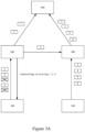
- Figures 3A and 3B illustrate schematic diagrams of uplink data forwarding in existing base station handover, to contrast against the process regarding uplink data in the communication method according to the second embodiment of the disclosure shown in Figure 4 .
- seamless handover there is a strict requirement regarding the time delay of data packet, and a certain degree of data packet loss (error) may be accepted.
- lossless handover there is a strict requirement regarding the packet loss rate (packet error rate), and a certain degree of data packet time delay may be accepted.
- the communication terminal needs to upload data packets 1, 2, 3, 4, 5, 6,... to the core network.
- the communication terminal 100 has sent to the first base station 200 data packets 1, 2, 3, 4, 5, wherein the first base station 200 receives data packets 1, 2, 4 successfully and sends acknowledge information that data packets 1, 2, 4 have been received.
- the communication terminal 100 disconnects the communication with the first base station 200, the communication terminal sends data packets to the second base station 300 other than the first base station 200. Since the last data packet which has been received sequentially and successfully by the first base station 200 is 2, in other words, the first data packet which is not sent to the first base station 200 by the communication terminal 100 successfully is 3, the communication terminal 100 begins to send to the second base station 300 the data packets from data packet 3.
- the first base station 200 sends to the core network 400 the sequential data packets 1, 2 received successfully, and performs data forwarding of data packet 4 to the second base station 300.
- the second base station 300 sends to the core network 400 the sequential data packets 3, 4, 5, 6 received successfully. Thereby, it is guaranteed that the data packet sequence sent to the core network 400 from the communication terminal 100 is complete, thereby a lossless handover is achieved.
- the communication terminal 100 may resend data packet 4 to the second base station 300 (as shown in Figure 3A ), or not resend data packet 4 to the second base station 300 but send data packets 3, 5, 6 to the second base station 300.
- the communication terminal 100 does not resend the data packets which have been sent successfully in order to guarantee real-time of the data packets, therefore as shown in Figure 3B , the communication terminal 100 sends to the second base station 300 data packets 6, 7, 8, 9.
- the first base station 200 sends the sequential data packets 1, 2 received successfully to the core network 400.
- the second base station 300 receives data packets 6, 7, 8, 9 from the communication terminal 100 successfully and sends data packets 6, 7, 8, 9 to the core network 400. Thereby, real-time of the data packets sent to the core network 400 from the communication terminal 100 is guaranteed, thereby a seamless handover is achieved.
- the data forwarding between base stations of LTE protocol is generally achieved through an X2 interface, and the communication between the base station and the core network, more accurately, the communication between the base station of LTE protocol and network units of Evolved Packet Core (EPC) core network is achieved through an S2 interface.
- EPC Evolved Packet Core
- the data packet resent between the base station and the core network and between the second base station 300 and the communication terminal 100 is not discussed in the disclosure.
- the disclosure it supposes that the data communication between the base station and the core network and between the second base station 300 and the communication terminal 100 is reliable and accurate.
- those skilled in the art may apply the features of the embodiments of the disclosure to the situation that a data packet resending problem occurs in the data communication between the base station and the core network and between the second base station 300 and the communication terminal 100.
- the communication terminal 100 may continue data packets which are being sent to the first base station 200, and after the connection between the communication terminal 100 and the second base station 300 is established, the communication terminal 100 may send to the second base station 300 the new data packets.
- the uplink data of the traffic which is determined to be communicated between the communication terminal 100 and the second base station 300 includes data packets 1, 2, 3, 4, 5, 6,..., wherein before the communication terminal 100 receives the acknowledge information, the communication terminal 100 sends to the first base station 200 data packets 1, 2, 3, 4, 5 successfully. Only data packets 1, 2, 4 have been received by the first base station 200 successfully, therefore the first base station 200 sends to the communication terminal 100 acknowledge information that data packets 1, 2, 4 have been received.
- the communication terminal 100 continues data packets which are being sent to the first base station 200 and data packets which have been sent to the first base station 200, that is, the communication terminal 100 resends data packets 3 and 5 based on the acknowledge information received from the first base station 200 until the first base station 200 receives data packets 3, 5 successfully. It should be noted that the communication terminal 100 does not send data packet 6 (a new data packet after determining that the inter-site carrier aggregation is performed) to the first base station 200.
- the communication terminal 100 After establishing the communication with the second base station 300, the communication terminal 100 send data packet 6 and the data packets thereafter to the second base station 300.
- the first base station 200 may directly send data packets 1, 2, 3, 4, 5 received from the communication terminal 100 to the core network 400.
- the manner shown in Figure 4A may be adopted to reduce packet loss rate, or as shown in Figure 4B , the communication terminal 100 does not resend data packets 3 and 5 to the first base station 200, but send data packet 6 to the second base station after establishing the communication with the second base station 300.
- the time that communication terminal 100 receives the information determining that the inter-site carrier aggregation is performed is far away from the time that the communication terminal 100 establishes the communication with the second base station 300, it is possible that the communication terminal 100 begins to send data to the second base station 300 from data packet 7 or 8 or sequent data packets thereafter, to satisfy the requirement to real-time of the carried traffic.
- the first base station 200 may send data packets 1, 2, 4 received from the communication terminal 100 to the core network 400, and the second base station 300 may send data packets 6, 7, 8, 9 received from the communication terminal 100 to the core network 400.
- the communication terminal 100 may continue data packets which are being sent to the first base station 200, and send to the second base station 300 the new data packets.
- the communication terminal 100 stops sending new data packets to the first base station 200 after establishing connection with the second base station 300
- the communication terminal 100 stops sending new data packets to the first base station 200 after receiving acknowledge information regarding the first base station 200 and the second base station 300 both performing data transmission connection with the communication terminal 100 on different carrier resources the amount of data packets to be transmitted at the first base station 200 is large. This is because that the time that the communication terminal 100 receives the above acknowledge information is earlier than the time that the communication terminal 100 establishes the connection with the second base station 300.
- the communication terminal 100 needs not to resend to the second base station 300 the data packet which has been sent to the first base station 200.
- the second embodiment of the disclosure is used for uplink data and the third embodiment of the disclosure is used for downlink data.
- Figures 5 illustrates a schematic diagram of downlink data in existing base station handover, to contrast against the process regarding downlink data in the communication method according to the third embodiment of the disclosure shown in Figures 6A , 6B .
- Figure 5 illustrates downlink data forwarding in the lossless handover, and downlink data forwarding in the seamless handover will be described with reference to Figure 5 .
- the core network 400 sends to the first base station 200 data packets 1, 2, 3, 4, 5, and the first base station 200 sends to the communication terminal 100 data packets 1, 2, 3, 4. Data packets 1, 2, 4 are received by the communication terminal 100 successfully, and the communication terminal 100 sends to the first base station 200 acknowledge information that data packets 1, 2, 4 are received.
- the core network 400 sends to the first base station 200 a data end symbol LP immediately after data packet 5. Therefore, from data packet 3, the first base station 200 forwards data packets 3, 4, 5 and the data end symbol LP immediately after data packet 5 to the second base station 300 based on the above acknowledge information.
- the core network 400 sends to the second base station 300 new data packets 6, 7, 8.
- the second base station 300 connects the new data packets 6, 7, 8 to data packets 3, 4, 5 based on the data end symbol LP, thereby data packets 3, 4, 5, 6, 7, 8 are sent to the communication terminal 100. Then, the lossless handover is completed.
- the first base station 200 begins to perform data forwarding to the second base station 300 from data packet 5.
- the first base station 200 forwards data packet 5 and the data end symbol LP immediately after data packet 5 to the second base station 300.
- the second base station 300 connects the new data packets 6, 7, 8 received from the core network 400 to data packets 5 based on the data end symbol LP, thereby data packets 5, 6, 7, 8 are sent to the communication terminal 100. Then, the seamless handover is completed.
- the communication terminal 100 may continue data packets which are being receiving from the first base station 200, and the first base station 200 performs data forwarding to the second base station 300 with respect to data packets not been sent to the communication terminal 100 yet and newly received from the core network 400.
- the notification information that the second base station 300 establishes connection with the communication terminal 100 may be sent to the first base station 200 by the second base station 300 or be sent to the first base station 200 by the communication terminal 100.
- the core network 400 sends to the first base station 200 data packets 1, 2, 3, 4, and the first base station 200 sends to the communication terminal 100 data packets 1, 2, 3, 4. Data packets 1, 2, 4 are received by the communication terminal 100 successfully, and therefore the communication terminal 100 sends to the first base station 200 acknowledge information that data packets 1, 2, 4 are received.
- the communication terminal 100 may continue data packets which are being receiving from the first base station 200, and not receive new data packets from the first base station 200. In other words, after the first base station 200 sends to the communication terminal 100 acknowledge information regarding the first base station 200 and the second base station 300 both connecting to the communication terminal 100, the first base station 200 does not send new data packets to the communication terminal 100.
- the first base station 200 guarantees that sending of data packet 3 to the communication terminal 100 is completed.
- the operation may be similar to that in the lossless handover to reduce packet loss rate, or data packet 3 may be discarded. In other words, data packet 3 will not be resent.
- the core network 400 After the first base station 200 sends to the communication terminal 100 acknowledge information regarding the first base station 200 and the second base station 300 both performing data transmission connection with the communication terminal 100 on different carrier resources, and until the core network 400 is notified that connection between the communication terminal 100 and the second base station 300 is established, the core network 400 continues to send data to the first base station 200. For example, as shown in Figure 6A , the core network 400 sends data packet 5 and the data end symbol LP immediately after data packet 5 to the first base station 200. Since the first base station 200 does not send new data packets to the communication terminal 100 after sending data packet 4 to the communication terminal 100, the first base station 200 forwards data packet 5 and the data end symbol LP immediately after data packet 5 to the second base station 300.
- notification information that the second base station 300 establishes connection with the communication terminal 100 may be directly sent to the core network 400 by the second base station 300.
- the second base station 300 may also send the notification information to the first base station 200, and the first base station 200 sends the notification information to the core network 400.
- the core network 400 After the core network 400 is notified that connection between the communication terminal 100 and the second base station 300 is established, the core network 400 sends to the second base station 300 data packets 6, 7, 8, 9.
- the second base station 300 connects data packets 6, 7, 8, 9 to data packets 5 based on the data end symbol LP, thereby data packets 5, 6, 7, 8, 9 are sent to the communication terminal 100.
- the communication terminal 100 may continue data packets which are being receiving from the first base station 200, and the first base station 200 performs data forwarding to the second base station 300 with respect to new data packets received from the core network 400.
- the specific processes of the lossless handover and the seamless handover are similar to those described with respect to Figures 6A , and the description thereof will be omitted.
- the difference between the above two examples of the communication method according to the third embodiment of the disclosure is only in that the first base station 200 does not send new data packets to the communication terminal 100, and the times of beginning to perform data forwarding to the second base station 300 with respect to the new data packets are different.
- the first base station 200 needs to forward the new data packets sent to the first base station 200 by the core network 400 to the second base station 300.
- the data packets which have been sent to the communication terminal 100 by the first base station 200 needs not to be forwarded to the communication terminal 100 through the second base station 300.
- FIG. 6B another example of the communication method according to the third embodiment of the disclosure is illustrated.
- the core network 400 continues to send new data packets to the first base station 200
- the first base station 200 performs data forwarding to the second base station 300 with respect to the new data packets received from the core network 400
- the second base station 300 send the new data packets received from the first base station 200 to the communication terminal 100.
- data forwarding of downlink data between the first base station 200 and the second station 300 is not performed.
- the core network 400 sends to the first base station 200 data packets 1, 2, 3, 4, and the first base station 200 sends to the communication terminal 100 data packets 1, 2, 3, 4.
- Data packets 1, 2, 4 are received by the communication terminal 100 successfully, and therefore the communication terminal 100 sends to the first base station 200 acknowledge information that data packets 1, 2, 4 are received.
- the communication terminal 100 may continue data packets which are being receiving from the first base station 200, not receive new data packets from the first base station 200, and begin to receive new data packets from the second base station 300.
- Figure 6B it is different from Figure 6A in that even though the core network 400 is notified that connection between the communication terminal 100 and the second base station 300 is established, the core network 400 continues to send new data packets to the first base station 200 and not begin to send new data packets to the second base station 300. The reason is that the quality of communication between the second base station 300 and the core network 400 is poorer than the quality of communication between the first base station 200 and the core network 400.
- the core network 400 may not be notified that connection between the communication terminal 100 and the second base station 300 is established, and therefore the core network 400 continues to send data packets of downlink data to the first base station 200. Likewise, the first base station 200 forwards the new data packets received from the core network 400 to the second base station 300.
- the data packets sent to the communication terminal 100 by the second base station 300 are forwarded by the first base station 200.
- the second base station 300 needs not to receive information for determining the core network number of the last data packet sent to the first base station 200 from the core network 400 or the core network number of the first data packet sent to the second base station 300 from the core network 400.
- information regarding connection between the communication terminal 100 and the second base station 300 being established is sent to the first base station 200 by the communication terminal 100 or the second base station 300, and is notified to the core network 400 by the first base station 200.
- downlink data needs to be forwarded.
- the downlink data needs not to be forwarded.
- connection between the communication terminal 100 and the second base station 300 is established, information regarding connection between the communication terminal 100 and the second base station 300 being established is sent to the core network 400.
- the core network 400 receives the information regarding connection between the communication terminal 100 and the second base station 300 being established, the core network 400 begins to send new data packets to the second base station 300, the first base station 200 continues data packets which are being sent to the communication terminal 100 and data packets which have been received from the core network 400, and the second base station 300 sends the new data packets received from the core network 400 to the communication terminal 100.
- the core network 400 sends to the first base station 200 data packets 1, 2, 3, 4, 5, and the first base station 200 sends to the communication terminal 100 data packets 1, 2, 3, 4. Data packets 1, 2, 4 are received by the communication terminal 100 successfully, and the communication terminal 100 sends to the first base station 200 acknowledge information that data packets 1, 2, 4 are received.
- the core network 400 sends to the first base station a data end symbol LP immediately after data packet 5 and begins to send data packets 6, 7, 8, 9 to the second base station 300.
- the first base station 200 continues to send data packet 5 (which has been received) before the data end symbol LP to the communication terminal 100.
- the first base station 200 may send the data end symbol LP to the second base station 300.
- the first base station 200 guarantees that sending of data packet 3 to the communication terminal 100 is completed.
- the operation may be similar to that in the lossless handover to reduce packet loss rate, or data packet 3 may be discarded. In other words, data packet 3 will not be resent.
- the second base station 300 sends the data packets 6, 7, 8, 9 received from the core network 400 to the communication terminal 100 base on the data end symbol LP.
- the data end symbol LP may indicate that the last data packet sent to the first base station 200 by the core network 400 is data packet 5.
- the core network 400 may also sends to the second base station 300 the data end symbol LP immediately before data packet 6.
- the data end symbol LP may indicate that the first data packet sent to the first base station 200 by the core network 400 is data packet 6. Therefore, the second base station 300 may determine which data packet the last data packet sent to the first base station 200 from the core network 400 is or which data packet the first data packet sent to the first base station 200 from the core network 400 is.
- data forwarding may not be performed between the first base station 200 and the second base station 300. It should be noted that since LP is only a symbol, the process of sending the data end symbol LP to the second base station 300 by the first base station 200 is not performing data forwarding between the first base station 200 and the second base station 300.
- the data end symbol is the number of data packet sent by the core network 400, and the number may be the wire transmission number of data packet.
- the first base station may send to the second base station air interface number information.
- the air interface number information is PDCP (Packet Data Convergence Protocol) data number, the content of which may be PDCP number of data packet 5 or 6 in Figure 7 , in order to guarantee that air interface data is processed in order on the terminal side.
- the first base station 200 may send to the second base station 300 PDCP number of the last data packet transmitted at the first base station 200 or PDCP number of the first data packet expected to be transmitted at the second base station 300.
- FIG. 8A illustrates a communication apparatus 800 according to the fifth embodiment of the disclosure.
- the communication apparatus 800 is on the first base station 200 side and used for changing the communication between base stations and the communication terminal 100, and comprises: a request sending unit 801 configured to send, in the case that a measuring result of signals of the second base station 300 from the communication terminal 100 which is communicating with the first base station 200 meets a predetermined condition, the second base station 300 a request regarding the first base station 200 and the second base station 300 both performing data transmission connection with the communication terminal 100 on different carrier resources, such that the first base station 200 and the second base station 300 both perform data transmission connection with the communication terminal 100 on different carrier resources; and an acknowledge transmission unit 803 configured to receive acknowledge information from the second base station 300 and send the acknowledge information to the communication terminal 100, wherein the acknowledge information comprises at least one of: with respect to which part of traffic of the communication terminal 100 the second base station 300 is able to communicate, a specific preamble for random access, system information of a new carrier on which the communication terminal 100 communicates with the second
- the request sending unit 801 may be used for performing a process corresponding to process 204 in Figure 2
- acknowledge transmission unit 803 may be used for performing a process corresponding to processes 206, 207 in Figure 2 .
- the communication apparatus 800 may comprise other units for performing processes corresponding to the other processes in the communication methods according to the first to fourth embodiments of the disclosure.
- the communication apparatus 800 may also comprise a function unit for sending to the communication terminal 100 control information for measuring signal of the second base station 300 (see process 201 in Figure 2 ); and a function unit for receiving a measuring result from the communication terminal 100 (see process 202 in Figure 2 ).
- the communication apparatus 800 may be an independent apparatus and operate in connection with the communication terminal 100, the first base station 200, the second base station 300 and the core network 400.
- the communication apparatus 800 may also be a part of the first base station 200.
- FIG 8B illustrates a communication apparatus 810 according to the fifth embodiment of the disclosure.
- the communication apparatus 810 is on the second base station 300 side for changing the communication between base stations and the communication terminal 100, and comprises: a request receiving unit 811 configured to receive, from the first base station 200, a request regarding the first base station 200 and the second base station 300 both performing data transmission connection with the communication terminal 100 on different carrier resources (see process 204 in Figure 2 ); and an acknowledge unit 812 configured to, after receiving the request from the first base station 200, generate an acknowledge information and send the acknowledge information to the first base station 200 (see processes 205, 206 in Figure 2 ), wherein the acknowledge information comprises at least one of: with respect to which part of traffic of the communication terminal 100 the second base station 300 is able to communicate, a specific preamble for random access, system information of a new carrier on which the communication terminal 100 communicates with the second base station 300, and configuration information of control plane protocol for establishing the communication between the communication terminal 100 and the second base station 300.
- the communication apparatus 810 may comprise other units for performing processes corresponding to the other processes in the communication methods according to the first to fourth embodiments of the disclosure.
- the communication apparatus 810 may also comprise a function unit for establishing connection with the communication terminal 100 (see process 209 in Figure 2 ); and a function unit for notifying the core network 400 of information regarding connection between the communication terminal 100 and the second base station 300 being established (see process 210 in Figure 2 ).
- the communication apparatus 810 may be an independent apparatus and operate in connection with the communication terminal 100, the first base station 200, the second base station 300 and the core network 400.
- the communication apparatus 810 may also be a part of the second base station 300.
- FIG 8C illustrates a communication apparatus 820 according to the fifth embodiment of the disclosure.
- the communication apparatus 820 is on the communication terminal side for changing the communication between base stations and the communication terminal, and comprises: an acknowledge receiving unit 821 configured to receive, in the case that it is determined that the first base station 200 and the second base station 300 both perform data transmission connection with the communication terminal 100 on different carrier resources, acknowledge information from the first base station 200 (see process 207 in Figure 2 ), wherein the acknowledge information comprises at least one of: with respect to which part of traffic of the communication terminal 100 the second base station 300 is able to communicate, a specific preamble for random access, system information of a new carrier on which the communication terminal 100 communicates with the second base station 300, and configuration information of control plane protocol for establishing the communication between the communication terminal 100 and the second base station 300; and a connection establishing unit 822 configured to, in the case of keeping the connection with the first base station 200, establish the connection with the second base station 300 (see process 200 in Figure 2 ).
- the communication apparatus 820 may comprise other units for performing processes corresponding to the other processes in the communication methods according to the first to fourth embodiments of the disclosure.
- the communication apparatus 820 may also comprise a function unit for receiving control information for measuring signal of the second base station 300 from the first base station 200 (see process 201 in Figure 2 ); and a function unit for sending a measuring result to the first base station 200 (see process 202 in Figure 2 ).
- the communication apparatus 820 may be an independent apparatus and operate in connection with the communication terminal 100, the first base station 200, the second base station 300 and the core network 400.
- the communication apparatus 820 may also be a part of the communication terminal 100.
- FIG. 8D illustrates a communication apparatus 830 according to the fifth embodiment of the disclosure.
- the communication apparatus 830 is on the core network 400 side for changing the communication between base stations and the communication terminal, and comprises: a notification receiving unit (831) configured to, after the communication terminal 100 which is communicating with a first base station 200 establishes the connection with a second base station 300 on a carrier resource which is different from that of the first base station 200, notification information regarding the first base station 200 and the second base station 300 both performing data transmission connection with the communication terminal 100 on different carrier resources from the first base station 200 or the second base station 300 (see process 210 in Figure 2 ); a first communication unit 832 configured to, after receiving the notification information, keep communicating with the communication terminal 100 via the first base station 200 (see the data packet communication between the first base station 200 and the core network 400 and between the first base station 200 and the communication terminal 100 shown in lower part of Figure 2 ); and a second communication unit 833 configured to, after receiving the notification information, begin to communicate with the communication terminal 100 via the second base station 300 (
- the communication apparatus 830 may comprise other units for performing processes corresponding to the other processes in the communication methods according to the first to fourth embodiments of the disclosure.
- the communication apparatus 830 may be an independent apparatus and operate in connection with the communication terminal 100, the first base station 200, the second base station 300 and the core network 400.
- the communication apparatus 830 may also be a part of the core network 400.
- the communication apparatuses and the function units thereof according to the fifth embodiment of the disclosure may be implemented in hardware, software or the combination thereof (for example, FPGA).
- Those algorithms and procedures included as part of the embodiments of the disclosure does not necessarily relate to any particular computer or other device unless otherwise indicated.
- various universal computers may be used by means of a program written according to the teaching herein, or a more dedicated equipment (for example, integrated circuit) may be constructed conveniently to perform required method steps or implement required function units.
- the invention may be embodied with one or more programs running on one or more programmable computer systems, in which each of programmable computer systems includes at least one processor, at least one data storage system (including volatile and nonvolatile memory and/or storage element), at least one input device or port and at least one output device or port.
- Program code may be applied to input data to perform the functions described herein and generate output information.
- the output information may be applied to one or more output devices in a known manner.
- the communication methods according to the first to fourth embodiments of the disclosure and the communication apparatus according to the fifth embodiment of the disclosure may be configured by software, firmware, hardware or the combination thereof.
- program constituting the software or firmware may be mounted to a machine having a dedicated hardware structure from a storage medium or network (for example, the universal computer 900 as illustrated in Fig. 9 ), when the computer is mounted with various programs, the computer may execute various functions.
- a central processing unit (CPU) 901 perform various processes according to the program stored in the Read-Only Memory (ROM) 902 or programs load from the storage unit 908 to the Random Access Memory (RAM) 903.
- RAM 903 store also data required when the CPU 901 performs various processes.
- CPU 901, ROM 902 and RAM 903 are connected from one to another via bus 904.
- Input/output interface 905 is also connected to the bus 904.
- input unit 906 including keyboard, mouse, etc.
- output unit 907 including display, such as cathode ray tube (CRT), liquid crystal display (LCD), etc., and speakers and so on
- storage unit 908 including hard disc, etc.
- communication part 909 including network interface cards such as LAN cards, modems and so on.
- the communication unit 909 performs communication process via network like the internet.
- drive 910 is also connected to the input/output interface 905.
- Detachable medium 911 such as disc, CD, magneto-optical disc, semiconductor memory, and so on is installed on the drive 910 based on requirements, such that the computer program read out therefrom is installed in the storage unit 908 based on requirements.
- programs constituting the software are installed from a network like the Internet or from a storage medium like the detachable medium 911.
- Such storage medium is not limited to the detachable medium 911 which is stored with programs and distributes separate from the method to provide a user with program as illustrated in Fig. 9 .
- the example of the detachable medium 911 includes disc (including floppy disc (registered marks)), CD (including CD read only memory (CD-ROM) and digital versatile disc (DVD)), magneto-optical disc (including mini-disc (MD) (registered marks)) and semiconductor memory.
- the storage medium may be ROM 902, or hard disc included in the storage unit 908 in which a program is stored and the program is distributed to a user with the method including the same.
- the disclosure also provides a program product storing machine readable instruction code.
- the instruction code may implement the communication methods according to the embodiments of the disclosure.
- various storage medium for carrying the program product such as magnetic disk, optical disk, magneto-optical disk, semiconductor memory, etc. is also included in the disclosure.
- an electronic device in one embodiment includes processing circuitry configured to establish a first wireless communication channel with a user equipment (UE). The device also determines whether a second communication channel of at least a predetermined quality exists between the UE and a non co-baseband basestation (BS) while the first communication channel between the UE and the electronics device is maintained. The first communication channel and the second communication channel use different carrier resources.
- UE user equipment
- BS non co-baseband basestation
- the processing circuitry is configured to inform the UE on the first communication channel of a determination that the UE is to establish and maintain the second communication channel with the non co-baseband BS while maintaining the first communication channel.
- the processing circuitry does not release data communications with the UE on the first communication channel while the UE establishes and maintains data communications with the non co-baseband BS on the second communications channel.
- the non co-baseband BS is not connected to the electronic device via an optical connection.
- the processing circuitry determines a manner of changing communications with the UE to include establishing and maintaining the second communication channel with the non co-baseband communication channel at least based on a measuring result of signals from the non co-baseband communication channel and the UE.
- the processing circuitry and the non co-baseband BS perform at least one of data transmission of respective control plane configurations, transmission on uplink control channel, and measurements of mobility and wireless link failure.
- the electronic device UE and non co-baseband BS share a common control plane.
- the common control plane is a radio resource control (RRC) protocol.
- RRC radio resource control
- a frequency band used in the first communication channel is different than a frequency band of the second communication channel.
- the processing circuitry is configured to receive from the non co-baseband BS at least one of an indication of which part of message traffic for the UE the non co-baseband BS is able to communicate, a preamble for random access, system information of a new carrier on which the UE communicates with the non co-baseband BS, and configuration information of control plane protocol for establishing communication between the communication terminal and the second base station.
- the processing circuitry performs lossless handover with the non co-baseband BS by forwarding to a core network sequential data packets and performs data forwarding of a successfully received non-sequential data packet to the non co-baseband BS for subsequent forwarding to the core network.
- the processing circuitry performs seamless handover with the non co-baseband BS by acknowledging packets that have been successfully received from the UE so the UE can send dropped packets to the non co-baseband BS for forwarding to a core network.
- the processing circuitry performs lossless handover with the non co-baseband BS by acknowledging packets that have been successfully received from the UE so the UE can resend lost packets to the processing circuitry for forwarding to a core network and the UE can also send different packets to the non co-baseband BS so the non co-baseband BS can forward the different packets to the core network.
- the processing circuitry performs seamless handover with the non co-baseband BS by acknowledging packets that have been successfully received from the UE for forwarding to a core network so the UE can also send different packets to the non co-baseband BS and the non co-baseband BS can forward the different packets to the core network.
- the processing circuitry is configured to stop receiving packets from the UE once the UE recognizes that the processing circuitry has failed to send an acknowledgement for a packet that the UE sent to the processing circuitry.
- the processing circuitry in a lossless handover in response to sending a first set of data packets on the first communication channel to the UE and receiving an acknowledge for only a subset of the first set, forwards dropped packets to the non co-baseband BS for relaying to the UE.
- the processing circuitry is configured to stop sending packets to the UE once an acknowledge message indicates that a packet was dropped, and in response the processing circuitry forwards at least one packet that was dropped and any newly received packet to the non co-baseband BS for relaying to the UE.
- the processing circuitry is configured to forward only the newly received packets to the non co-baseband BS for relaying to the UE.
- the processing circuitry is configured to send data packets to the UE from a core network, and once a data end symbol is received, the processing circuitry forwards the data end symbol to the non co-baseband BS for relaying to the UE.
- a communications method that establishes a first wireless communication channel between a first basestation and a user equipment (UE); determining with processing circuitry whether a second communication channel of at least predetermined quality exists between the UE and a non co-baseband BS while the first communication channel between the UE and the electronics device is maintained, wherein the first communication channel and the second communication channel use different carrier resources.
- UE user equipment
- the device has instructions stored therein that when executed by processing circuitry perform a communications method, the method comprising: establishing a first wireless communication channel between a first basestation and a user equipment (UE); determining with the processing circuitry whether a second communication channel of at least predetermined quality exists between the UE and a non co-baseband BS while the first communication channel between the UE and the electronics device is maintained, wherein the first communication channel and the second communication channel use different carrier resources.
- a communications method comprising: establishing a first wireless communication channel between a first basestation and a user equipment (UE); determining with the processing circuitry whether a second communication channel of at least predetermined quality exists between the UE and a non co-baseband BS while the first communication channel between the UE and the electronics device is maintained, wherein the first communication channel and the second communication channel use different carrier resources.
Landscapes
- Engineering & Computer Science (AREA)
- Computer Networks & Wireless Communication (AREA)
- Signal Processing (AREA)
- Mobile Radio Communication Systems (AREA)
- Reduction Or Emphasis Of Bandwidth Of Signals (AREA)
- Electroluminescent Light Sources (AREA)
- Communication Control (AREA)
Claims (7)
- Dispositif électronique d'une première station de base (200), conçu pour maintenir un premier canal de communication avec un équipement utilisateur (100), le dispositif électronique comprenant :
des circuits, configurés pour :envoyer à l'équipement utilisateur, des informations de configuration de mesure pour mesurer un signal d'une deuxième station de base (300) ;recevoir, à partir de l'équipement utilisateur, un résultat de mesure de la deuxième station de base en fonction des informations de configuration de mesure ;envoyer, à la deuxième station de base, une demande concernant l'équipement utilisateur pour établir une communication avec la deuxième station de base pendant le maintien du premier canal de communication ;recevoir, à partir de la deuxième station de base, des informations d'acquittement comprenant des informations de configuration permettant à l'équipement utilisateur d'établir une communication avec la deuxième station de base ;en fonction des informations d'acquittement, envoyer, à l'équipement utilisateur, des informations de configuration de commande de ressources radio RRC, comprenant les informations d'acquittement, pour établir un deuxième canal de communication avec la deuxième station de base pendant le maintien du premier canal de communication ;dans lequel les bandes de fréquences utilisées pour une communication entre la première station de base et l'équipement utilisateur sont différentes des bandes de fréquences utilisées pour une communication entre l'équipement utilisateur et la deuxième station de base. - Dispositif électronique selon la revendication 1, dans lequel, dans le cas où le résultat de mesure satisfait une condition prédéterminée, les circuits sont configurés pour envoyer, à la deuxième station de base, la demande concernant l'équipement utilisateur pour établir une communication avec la deuxième station de base durant le maintien du premier canal de communication.
- Dispositif électronique selon la revendication 1, dans lequel, après l'établissement du deuxième canal de communication, les circuits et la station de base réalisent une transmission à l'équipement utilisateur selon des configurations de protocole de plan de commande respectives et des mesures de mobilité et de défaillance de liaison sans fil.
- Dispositif électronique selon la revendication 1 ou 3, dans lequel, après l'établissement du deuxième canal de communication, il existe des porteuses primaires indépendantes respectivement dans la communication entre l'équipement utilisateur et la première station de base et dans la communication entre l'équipement utilisateur et la deuxième station de base.
- Dispositif électronique selon la revendication 1, dans lequel les informations d'acquittement comprennent au moins un : d'une indication de la partie du trafic de l'équipement utilisateur que la deuxième station de base est en mesure de communiquer, d'un préambule spécifique pour un accès aléatoire, d'informations système d'une nouvelle porteuse sur laquelle l'équipement utilisateur communique avec la deuxième station de base, et d'informations de configuration de protocole de plan de commande pour établir la communication entre l'équipement utilisateur et la deuxième station de base.
- Dispositif électronique d'un équipement utilisateur (100), le dispositif électronique comprenant :
des circuits configurés pour :recevoir, à partir d'une première station de base (200), une configuration de mesure pour mesurer un signal d'une deuxième station de base (300) ;mesurer et communiquer à la première station de base un résultat de mesure de la deuxième station de base, en fonction des informations de configuration de mesure ;et recevoir, à partir de la première station de base, des informations de configuration de commande de ressources radio, RRC, pour établir un deuxième canal de communication avec la deuxième station de base pendant le maintien du premier canal de communication, les informations de configuration de RRC comprenant des informations d'acquittement de la deuxième station de base, les informations d'acquittement comprenant au moins un : d'une indication de la partie du trafic de l'équipement utilisateur que la deuxième base la station est en mesure de communiquer, d'un préambule pour un accès aléatoire, d'informations système d'une nouvelle porteuse sur laquelle le dispositif électronique communique avec la deuxième station de base, et d'informations de configuration de protocole de plan de commande pour établir une communication entre l'équipement utilisateur et la deuxième station de base ;dans lequel les bandes de fréquences utilisées pour une communication entre l'équipement utilisateur et la première station de base sont différentes des bandes de fréquences utilisées pour une communication entre l'équipement utilisateur et la deuxième station de base. - Dispositif électronique d'une deuxième station de base (300), le dispositif électronique comprenant des circuits configurés pour :recevoir, à partir d'une première station de base (200), une demande concernant un équipement utilisateur (100) pour établir une communication avec la deuxième station de base pendant le maintien d'un premier canal de communication entre l'équipement utilisateur et la première station de base ;générer des informations d'acquittement comprenant des informations de configuration permettant à l'équipement utilisateur d'établir une communication avec la deuxième station de base ;envoyer, à la première station de base, les informations d'acquittement, dans lequel les informations d'acquittement sont destinées à l'équipement utilisateur pour établir, en fonction des informations d'accusé de réception, un deuxième canal de communication avec la deuxième station de base durant le maintien du premier canal de communication ;dans lequel les bandes de fréquences utilisées pour une communication entre l'équipement utilisateur et la première station de base sont différentes des bandes de fréquences utilisées pour une communication entre la deuxième station de base et l'équipement utilisateur.
Priority Applications (1)
| Application Number | Priority Date | Filing Date | Title |
|---|---|---|---|
| RS20230675A RS64452B1 (sr) | 2013-06-18 | 2014-06-16 | Aparat za komunikaciju i način komunikacije |
Applications Claiming Priority (4)
| Application Number | Priority Date | Filing Date | Title |
|---|---|---|---|
| CN201310240852.3A CN104244349B (zh) | 2013-06-18 | 2013-06-18 | 通信装置和通信方法 |
| PCT/CN2014/079934 WO2014201985A1 (fr) | 2013-06-18 | 2014-06-16 | Appareil de communication, et procédé de communication |
| EP14814234.2A EP3011774B1 (fr) | 2013-06-18 | 2014-06-16 | Appareil de communication, et procédé de communication |
| EP18174062.2A EP3402245B1 (fr) | 2013-06-18 | 2014-06-16 | Procédé de communication et appareil de communication |
Related Parent Applications (3)
| Application Number | Title | Priority Date | Filing Date |
|---|---|---|---|
| EP14814234.2A Division EP3011774B1 (fr) | 2013-06-18 | 2014-06-16 | Appareil de communication, et procédé de communication |
| EP18174062.2A Division EP3402245B1 (fr) | 2013-06-18 | 2014-06-16 | Procédé de communication et appareil de communication |
| EP18174062.2A Division-Into EP3402245B1 (fr) | 2013-06-18 | 2014-06-16 | Procédé de communication et appareil de communication |
Publications (3)
| Publication Number | Publication Date |
|---|---|
| EP3767996A2 EP3767996A2 (fr) | 2021-01-20 |
| EP3767996A3 EP3767996A3 (fr) | 2021-03-03 |
| EP3767996B1 true EP3767996B1 (fr) | 2023-07-26 |
Family
ID=52103955
Family Applications (3)
| Application Number | Title | Priority Date | Filing Date |
|---|---|---|---|
| EP14814234.2A Active EP3011774B1 (fr) | 2013-06-18 | 2014-06-16 | Appareil de communication, et procédé de communication |
| EP20177781.0A Active EP3767996B1 (fr) | 2013-06-18 | 2014-06-16 | Appareil et procédé de communication |
| EP18174062.2A Active EP3402245B1 (fr) | 2013-06-18 | 2014-06-16 | Procédé de communication et appareil de communication |
Family Applications Before (1)
| Application Number | Title | Priority Date | Filing Date |
|---|---|---|---|
| EP14814234.2A Active EP3011774B1 (fr) | 2013-06-18 | 2014-06-16 | Appareil de communication, et procédé de communication |
Family Applications After (1)
| Application Number | Title | Priority Date | Filing Date |
|---|---|---|---|
| EP18174062.2A Active EP3402245B1 (fr) | 2013-06-18 | 2014-06-16 | Procédé de communication et appareil de communication |
Country Status (15)
| Country | Link |
|---|---|
| US (2) | US9681353B2 (fr) |
| EP (3) | EP3011774B1 (fr) |
| JP (3) | JP6222352B2 (fr) |
| KR (2) | KR102219052B1 (fr) |
| CN (3) | CN113411851A (fr) |
| AU (2) | AU2014283892B2 (fr) |
| BR (1) | BR112015031472B1 (fr) |
| CA (1) | CA2914274C (fr) |
| ES (1) | ES2953840T3 (fr) |
| FI (1) | FI3767996T3 (fr) |
| MX (1) | MX351235B (fr) |
| RS (1) | RS64452B1 (fr) |
| RU (1) | RU2677693C2 (fr) |
| WO (1) | WO2014201985A1 (fr) |
| ZA (1) | ZA201508511B (fr) |
Families Citing this family (12)
| Publication number | Priority date | Publication date | Assignee | Title |
|---|---|---|---|---|
| CN113411851A (zh) * | 2013-06-18 | 2021-09-17 | 索尼公司 | 通信装置 |
| US10045362B2 (en) * | 2014-04-15 | 2018-08-07 | Telefonaktiebolaget Lm Ericsson (Publ) | Uplink based selection of downlink connectivity configuration |
| EP3177072B1 (fr) * | 2014-07-23 | 2018-10-03 | Huawei Technologies Co. Ltd. | Dispositifs et procédés d'envoi de paquet de données et de traitement de données |
| US10244444B2 (en) | 2015-03-04 | 2019-03-26 | Qualcomm Incorporated | Dual link handover |
| WO2018036620A1 (fr) * | 2016-08-23 | 2018-03-01 | Telefonaktiebolaget Lm Ericsson (Publ) | Réseau de transport, nœud et procédé |
| WO2018066777A2 (fr) * | 2016-10-04 | 2018-04-12 | 삼성전자 주식회사 | Dispositif de communication sans fil, et procédé de commande associé |
| KR20180037556A (ko) | 2016-10-04 | 2018-04-12 | 삼성전자주식회사 | 무선 통신 장치 및 그 제어 방법 |
| US10531346B2 (en) * | 2017-10-25 | 2020-01-07 | Qualcomm Incorporated | Techniques and apparatuses for compression enabled bearer management |
| CN109644409B (zh) | 2018-01-09 | 2020-10-09 | Oppo广东移动通信有限公司 | 终端发送数据的控制方法、终端设备及计算机存储介质 |
| WO2020097850A1 (fr) * | 2018-11-15 | 2020-05-22 | Oppo广东移动通信有限公司 | Procédé et appareil de transmission de données |
| US10914349B1 (en) | 2019-08-29 | 2021-02-09 | Kawasaki Jukogyo Kabushiki Kaisha | Power unit of utility vehicle |
| KR20210067461A (ko) * | 2019-11-29 | 2021-06-08 | 삼성전자주식회사 | 무선 통신 시스템에서 동적으로 주파수 자원을 공유하기 위한 방법 및 장치 |
Family Cites Families (35)
| Publication number | Priority date | Publication date | Assignee | Title |
|---|---|---|---|---|
| US7876729B1 (en) * | 1998-07-20 | 2011-01-25 | Qualcomm Incorporated | Intersystem base station handover |
| EP1257141B1 (fr) * | 2001-05-10 | 2007-01-03 | Nortel Networks Limited | Système et méthode pour la redirection de transmission entre les réseaux de télécommunication mobiles avec différentes technologies d'acces radio |
| EP1545139A1 (fr) * | 2003-12-19 | 2005-06-22 | Telefonaktiebolaget LM Ericsson (publ) | Procédé et système pour mettre à disposition une connexion continue utilisant une station mobile comme relais |
| GB2435151B (en) * | 2006-02-08 | 2008-05-28 | Motorola Inc | Soft handover in a cellular communication system |
| CN101022652A (zh) * | 2006-02-15 | 2007-08-22 | 华为技术有限公司 | 对业务进行切换的方法、采用该方法的设备和系统 |
| CN100428830C (zh) | 2006-08-08 | 2008-10-22 | 华为技术有限公司 | 移动通信系统中邻区干扰抑制方法及基站节点 |
| US20080095133A1 (en) | 2006-10-23 | 2008-04-24 | Shu Kodo | Method for reducing inter-cell interference in communications system |
| US8504038B2 (en) * | 2007-03-20 | 2013-08-06 | Nec Corporation | Base station, mobile communication system using the base station, and data transfer method |
| US8265628B2 (en) * | 2007-04-25 | 2012-09-11 | Telefonaktiebolaget Lm Ericsson (Publ) | Method and apparatus for seamless handover in a wireless communication network |
| US8594069B2 (en) * | 2007-08-06 | 2013-11-26 | Qualcomm Incorporated | In-order data delivery during handover in a wireless communication system |
| TWI495363B (zh) * | 2007-08-13 | 2015-08-01 | Qualcomm Inc | 於無線通信交遞時資料封包之依序傳遞最佳化 |
| CN102651892B (zh) * | 2007-09-29 | 2016-03-30 | 华为技术有限公司 | 基于s1切换的下行及上行数据包转发方法 |
| US8929891B2 (en) * | 2007-10-02 | 2015-01-06 | Blackberry Limited | Measurement control for handover from one radio access technology to another |
| GB2454650A (en) * | 2007-10-29 | 2009-05-20 | Nec Corp | Resource Allocation for persistently allocated resources |
| US9065646B2 (en) * | 2008-02-04 | 2015-06-23 | Nokia Solutions And Networks Oy | ACK/NACK channelization for resource blocks containing both ACK/NACK and CQI |
| CN101572922B (zh) * | 2008-04-28 | 2011-04-13 | 大唐移动通信设备有限公司 | 切换过程中用户平面处理方法及设备 |
| CN101635968A (zh) * | 2008-07-22 | 2010-01-27 | 株式会社Ntt都科摩 | 切换处理方法、基站及网络通信系统 |
| CN101677461B (zh) * | 2008-09-16 | 2011-09-28 | 鼎桥通信技术有限公司 | 实现高速下行分组业务和多媒体广播业务并发的方法 |
| WO2010104365A2 (fr) * | 2009-03-13 | 2010-09-16 | 엘지전자 주식회사 | Transfert effectué en considération d'une configuration de porteuse composante de liaison montante/liaison descendante |
| CN102356674B (zh) * | 2009-03-17 | 2015-07-29 | 诺基亚公司 | 干扰控制 |
| CN101860931B (zh) * | 2009-04-09 | 2013-04-24 | 电信科学技术研究院 | 一种多载波聚合系统的小区切换方法和系统 |
| CN101883406B (zh) * | 2009-05-07 | 2015-04-08 | 株式会社Ntt都科摩 | 一种切换方法、移动终端及基站 |
| CN101583123B (zh) * | 2009-06-15 | 2011-06-08 | 华为技术有限公司 | 分组域系统间的切换方法、装置及系统 |
| CN101998547B (zh) * | 2009-08-18 | 2013-08-07 | 华为技术有限公司 | 数据前转方法、基站和中继站 |
| US9392515B2 (en) * | 2010-02-12 | 2016-07-12 | Interdigital Technology Corporation | Data split between multiple sites |
| KR20110111790A (ko) * | 2010-04-05 | 2011-10-12 | 주식회사 팬택 | 다중 요소 반송파를 사용하는 무선 통신 시스템에서의 핸드오버 시 요소반송파 정보 시그널링 방법 및 장치 |
| KR101467965B1 (ko) * | 2010-05-03 | 2014-12-10 | 알까뗄 루슨트 | 반송파 집성을 갖는 무선 통신 네트워크에서 이용된 핸드오버 방법 및 그의 장치 |
| US8792365B2 (en) * | 2010-05-26 | 2014-07-29 | Qualcomm Incorporated | Service-based inter-radio access technology (inter-RAT) handover |
| CN103339984B (zh) * | 2011-01-27 | 2017-04-26 | 日本电气株式会社 | 基站、移动台、通信控制系统和通信控制方法 |
| US8654728B2 (en) * | 2011-04-29 | 2014-02-18 | Telefonaktiebolaget L M Ericsson (Publ) | Generating uplink signals from user equipment nodes to identify interferers to a network node |
| CN103609158B (zh) * | 2011-06-17 | 2017-05-24 | 富士通株式会社 | 通信系统、数据中继装置、基站、移动终端以及通信方法 |
| US9402253B2 (en) * | 2012-08-01 | 2016-07-26 | Lg Electronics Inc. | Method for signaling control information, and apparatus therefor |
| US9584300B2 (en) * | 2013-01-03 | 2017-02-28 | Lg Electronics Inc. | Configuring uplink subframes and controlling power in a carrier aggregation system when the DCI format has first or second identifiers |
| JP6143524B2 (ja) * | 2013-04-05 | 2017-06-07 | 京セラ株式会社 | 移動通信システム、無線基地局及びユーザ端末 |
| CN113411851A (zh) * | 2013-06-18 | 2021-09-17 | 索尼公司 | 通信装置 |
-
2013
- 2013-06-18 CN CN202110583707.XA patent/CN113411851A/zh active Pending
- 2013-06-18 CN CN202110585437.6A patent/CN113411852A/zh active Pending
- 2013-06-18 CN CN201310240852.3A patent/CN104244349B/zh active Active
-
2014
- 2014-06-16 RS RS20230675A patent/RS64452B1/sr unknown
- 2014-06-16 FI FIEP20177781.0T patent/FI3767996T3/fi active
- 2014-06-16 KR KR1020167000177A patent/KR102219052B1/ko active IP Right Grant
- 2014-06-16 RU RU2016101181A patent/RU2677693C2/ru active
- 2014-06-16 AU AU2014283892A patent/AU2014283892B2/en active Active
- 2014-06-16 CA CA2914274A patent/CA2914274C/fr active Active
- 2014-06-16 ES ES20177781T patent/ES2953840T3/es active Active
- 2014-06-16 MX MX2015016992A patent/MX351235B/es active IP Right Grant
- 2014-06-16 BR BR112015031472-4A patent/BR112015031472B1/pt active IP Right Grant
- 2014-06-16 US US14/892,394 patent/US9681353B2/en active Active
- 2014-06-16 KR KR1020217004683A patent/KR102295462B1/ko active IP Right Grant
- 2014-06-16 EP EP14814234.2A patent/EP3011774B1/fr active Active
- 2014-06-16 JP JP2016520262A patent/JP6222352B2/ja active Active
- 2014-06-16 EP EP20177781.0A patent/EP3767996B1/fr active Active
- 2014-06-16 WO PCT/CN2014/079934 patent/WO2014201985A1/fr active Application Filing
- 2014-06-16 EP EP18174062.2A patent/EP3402245B1/fr active Active
-
2015
- 2015-11-18 ZA ZA2015/08511A patent/ZA201508511B/en unknown
-
2017
- 2017-04-24 US US15/495,292 patent/US10420000B2/en active Active
- 2017-10-05 JP JP2017195281A patent/JP2018023161A/ja active Pending
-
2018
- 2018-10-12 AU AU2018247332A patent/AU2018247332B2/en active Active
-
2019
- 2019-05-27 JP JP2019098871A patent/JP6816791B2/ja active Active
Also Published As
Similar Documents
| Publication | Publication Date | Title |
|---|---|---|
| AU2018247332B2 (en) | Communication apparatus and communication method | |
| TWI717582B (zh) | 對資料封包進行映射的方法及使用所述方法的相關裝置 | |
| US9949179B2 (en) | Method and device for indicating D2D related information and determining D2D transmission resource | |
| EP3014944B1 (fr) | Réponse commandée par station de base maître à une défaillance de liaison radio détectée entre station de base secondaire et station mobile dans des réseaux sans fil à double connectivité | |
| JP2017514367A (ja) | ベアラ管理装置、方法及び通信システム | |
| US20180027456A1 (en) | Base station | |
| JP2022125271A (ja) | ビームフォーミングに関連する端末装置、基地局、及び、方法 | |
| JP2018093493A (ja) | ハンドオーバ後のデータ伝送を取り扱うデバイス及び方法 | |
| US20200322094A1 (en) | Submitting a PDCP PDU for Transmission | |
| US10588058B2 (en) | User equipment, base station and communication method | |
| JP2018174597A (ja) | ベアラ管理装置、方法及び通信システム | |
| US10742365B2 (en) | Apparatus and method for radio communication |
Legal Events
| Date | Code | Title | Description |
|---|---|---|---|
| PUAI | Public reference made under article 153(3) epc to a published international application that has entered the european phase |
Free format text: ORIGINAL CODE: 0009012 |
|
| STAA | Information on the status of an ep patent application or granted ep patent |
Free format text: STATUS: REQUEST FOR EXAMINATION WAS MADE |
|
| 17P | Request for examination filed |
Effective date: 20200618 |
|
| AC | Divisional application: reference to earlier application |
Ref document number: 3402245 Country of ref document: EP Kind code of ref document: P Ref document number: 3011774 Country of ref document: EP Kind code of ref document: P |
|
| AK | Designated contracting states |
Kind code of ref document: A2 Designated state(s): AL AT BE BG CH CY CZ DE DK EE ES FI FR GB GR HR HU IE IS IT LI LT LU LV MC MK MT NL NO PL PT RO RS SE SI SK SM TR |
|
| PUAL | Search report despatched |
Free format text: ORIGINAL CODE: 0009013 |
|
| AK | Designated contracting states |
Kind code of ref document: A3 Designated state(s): AL AT BE BG CH CY CZ DE DK EE ES FI FR GB GR HR HU IE IS IT LI LT LU LV MC MK MT NL NO PL PT RO RS SE SI SK SM TR |
|
| RIC1 | Information provided on ipc code assigned before grant |
Ipc: H04W 36/30 20090101ALI20210125BHEP Ipc: H04W 36/00 20090101ALI20210125BHEP Ipc: H04W 36/02 20090101AFI20210125BHEP |
|
| RAP3 | Party data changed (applicant data changed or rights of an application transferred) |
Owner name: SONY GROUP CORPORATION |
|
| GRAP | Despatch of communication of intention to grant a patent |
Free format text: ORIGINAL CODE: EPIDOSNIGR1 |
|
| STAA | Information on the status of an ep patent application or granted ep patent |
Free format text: STATUS: GRANT OF PATENT IS INTENDED |
|
| INTG | Intention to grant announced |
Effective date: 20221208 |
|
| GRAS | Grant fee paid |
Free format text: ORIGINAL CODE: EPIDOSNIGR3 |
|
| GRAF | Information related to payment of grant fee modified |
Free format text: ORIGINAL CODE: EPIDOSCIGR3 |
|
| GRAA | (expected) grant |
Free format text: ORIGINAL CODE: 0009210 |
|
| STAA | Information on the status of an ep patent application or granted ep patent |
Free format text: STATUS: THE PATENT HAS BEEN GRANTED |
|
| AC | Divisional application: reference to earlier application |
Ref document number: 3011774 Country of ref document: EP Kind code of ref document: P Ref document number: 3402245 Country of ref document: EP Kind code of ref document: P |
|
| AK | Designated contracting states |
Kind code of ref document: B1 Designated state(s): AL AT BE BG CH CY CZ DE DK EE ES FI FR GB GR HR HU IE IS IT LI LT LU LV MC MK MT NL NO PL PT RO RS SE SI SK SM TR |
|
| REG | Reference to a national code |
Ref country code: CH Ref legal event code: EP |
|
| REG | Reference to a national code |
Ref country code: DE Ref legal event code: R096 Ref document number: 602014087802 Country of ref document: DE |
|
| REG | Reference to a national code |
Ref country code: IE Ref legal event code: FG4D |
|
| REG | Reference to a national code |
Ref country code: NL Ref legal event code: FP |
|
| REG | Reference to a national code |
Ref country code: SE Ref legal event code: TRGR |
|
| REG | Reference to a national code |
Ref country code: LT Ref legal event code: MG9D |
|
| REG | Reference to a national code |
Ref country code: ES Ref legal event code: FG2A Ref document number: 2953840 Country of ref document: ES Kind code of ref document: T3 Effective date: 20231116 |
|
| REG | Reference to a national code |
Ref country code: AT Ref legal event code: MK05 Ref document number: 1593394 Country of ref document: AT Kind code of ref document: T Effective date: 20230726 |
|
| PG25 | Lapsed in a contracting state [announced via postgrant information from national office to epo] |
Ref country code: GR Free format text: LAPSE BECAUSE OF FAILURE TO SUBMIT A TRANSLATION OF THE DESCRIPTION OR TO PAY THE FEE WITHIN THE PRESCRIBED TIME-LIMIT Effective date: 20231027 |
|
| PG25 | Lapsed in a contracting state [announced via postgrant information from national office to epo] |
Ref country code: IS Free format text: LAPSE BECAUSE OF FAILURE TO SUBMIT A TRANSLATION OF THE DESCRIPTION OR TO PAY THE FEE WITHIN THE PRESCRIBED TIME-LIMIT Effective date: 20231126 |
|
| PG25 | Lapsed in a contracting state [announced via postgrant information from national office to epo] |
Ref country code: PT Free format text: LAPSE BECAUSE OF FAILURE TO SUBMIT A TRANSLATION OF THE DESCRIPTION OR TO PAY THE FEE WITHIN THE PRESCRIBED TIME-LIMIT Effective date: 20231127 Ref country code: NO Free format text: LAPSE BECAUSE OF FAILURE TO SUBMIT A TRANSLATION OF THE DESCRIPTION OR TO PAY THE FEE WITHIN THE PRESCRIBED TIME-LIMIT Effective date: 20231026 Ref country code: LV Free format text: LAPSE BECAUSE OF FAILURE TO SUBMIT A TRANSLATION OF THE DESCRIPTION OR TO PAY THE FEE WITHIN THE PRESCRIBED TIME-LIMIT Effective date: 20230726 Ref country code: LT Free format text: LAPSE BECAUSE OF FAILURE TO SUBMIT A TRANSLATION OF THE DESCRIPTION OR TO PAY THE FEE WITHIN THE PRESCRIBED TIME-LIMIT Effective date: 20230726 Ref country code: IS Free format text: LAPSE BECAUSE OF FAILURE TO SUBMIT A TRANSLATION OF THE DESCRIPTION OR TO PAY THE FEE WITHIN THE PRESCRIBED TIME-LIMIT Effective date: 20231126 Ref country code: HR Free format text: LAPSE BECAUSE OF FAILURE TO SUBMIT A TRANSLATION OF THE DESCRIPTION OR TO PAY THE FEE WITHIN THE PRESCRIBED TIME-LIMIT Effective date: 20230726 Ref country code: GR Free format text: LAPSE BECAUSE OF FAILURE TO SUBMIT A TRANSLATION OF THE DESCRIPTION OR TO PAY THE FEE WITHIN THE PRESCRIBED TIME-LIMIT Effective date: 20231027 Ref country code: AT Free format text: LAPSE BECAUSE OF FAILURE TO SUBMIT A TRANSLATION OF THE DESCRIPTION OR TO PAY THE FEE WITHIN THE PRESCRIBED TIME-LIMIT Effective date: 20230726 |
|
| PG25 | Lapsed in a contracting state [announced via postgrant information from national office to epo] |
Ref country code: PL Free format text: LAPSE BECAUSE OF FAILURE TO SUBMIT A TRANSLATION OF THE DESCRIPTION OR TO PAY THE FEE WITHIN THE PRESCRIBED TIME-LIMIT Effective date: 20230726 |
|
| PG25 | Lapsed in a contracting state [announced via postgrant information from national office to epo] |
Ref country code: SM Free format text: LAPSE BECAUSE OF FAILURE TO SUBMIT A TRANSLATION OF THE DESCRIPTION OR TO PAY THE FEE WITHIN THE PRESCRIBED TIME-LIMIT Effective date: 20230726 Ref country code: RO Free format text: LAPSE BECAUSE OF FAILURE TO SUBMIT A TRANSLATION OF THE DESCRIPTION OR TO PAY THE FEE WITHIN THE PRESCRIBED TIME-LIMIT Effective date: 20230726 Ref country code: EE Free format text: LAPSE BECAUSE OF FAILURE TO SUBMIT A TRANSLATION OF THE DESCRIPTION OR TO PAY THE FEE WITHIN THE PRESCRIBED TIME-LIMIT Effective date: 20230726 Ref country code: DK Free format text: LAPSE BECAUSE OF FAILURE TO SUBMIT A TRANSLATION OF THE DESCRIPTION OR TO PAY THE FEE WITHIN THE PRESCRIBED TIME-LIMIT Effective date: 20230726 Ref country code: CZ Free format text: LAPSE BECAUSE OF FAILURE TO SUBMIT A TRANSLATION OF THE DESCRIPTION OR TO PAY THE FEE WITHIN THE PRESCRIBED TIME-LIMIT Effective date: 20230726 Ref country code: SK Free format text: LAPSE BECAUSE OF FAILURE TO SUBMIT A TRANSLATION OF THE DESCRIPTION OR TO PAY THE FEE WITHIN THE PRESCRIBED TIME-LIMIT Effective date: 20230726 |