EP3767816A1 - Current detection device - Google Patents
Current detection device Download PDFInfo
- Publication number
- EP3767816A1 EP3767816A1 EP20183678.0A EP20183678A EP3767816A1 EP 3767816 A1 EP3767816 A1 EP 3767816A1 EP 20183678 A EP20183678 A EP 20183678A EP 3767816 A1 EP3767816 A1 EP 3767816A1
- Authority
- EP
- European Patent Office
- Prior art keywords
- current
- coil
- path
- detection device
- induction
- Prior art date
- Legal status (The legal status is an assumption and is not a legal conclusion. Google has not performed a legal analysis and makes no representation as to the accuracy of the status listed.)
- Ceased
Links
Images



Classifications
-
- H—ELECTRICITY
- H02—GENERATION; CONVERSION OR DISTRIBUTION OF ELECTRIC POWER
- H02M—APPARATUS FOR CONVERSION BETWEEN AC AND AC, BETWEEN AC AND DC, OR BETWEEN DC AND DC, AND FOR USE WITH MAINS OR SIMILAR POWER SUPPLY SYSTEMS; CONVERSION OF DC OR AC INPUT POWER INTO SURGE OUTPUT POWER; CONTROL OR REGULATION THEREOF
- H02M7/00—Conversion of AC power input into DC power output; Conversion of DC power input into AC power output
- H02M7/42—Conversion of DC power input into AC power output without possibility of reversal
- H02M7/44—Conversion of DC power input into AC power output without possibility of reversal by static converters
- H02M7/48—Conversion of DC power input into AC power output without possibility of reversal by static converters using discharge tubes with control electrode or semiconductor devices with control electrode
- H02M7/53—Conversion of DC power input into AC power output without possibility of reversal by static converters using discharge tubes with control electrode or semiconductor devices with control electrode using devices of a triode or transistor type requiring continuous application of a control signal
- H02M7/537—Conversion of DC power input into AC power output without possibility of reversal by static converters using discharge tubes with control electrode or semiconductor devices with control electrode using devices of a triode or transistor type requiring continuous application of a control signal using semiconductor devices only, e.g. single switched pulse inverters
- H02M7/5387—Conversion of DC power input into AC power output without possibility of reversal by static converters using discharge tubes with control electrode or semiconductor devices with control electrode using devices of a triode or transistor type requiring continuous application of a control signal using semiconductor devices only, e.g. single switched pulse inverters in a bridge configuration
-
- G—PHYSICS
- G01—MEASURING; TESTING
- G01R—MEASURING ELECTRIC VARIABLES; MEASURING MAGNETIC VARIABLES
- G01R15/00—Details of measuring arrangements of the types provided for in groups G01R17/00 - G01R29/00, G01R33/00 - G01R33/26 or G01R35/00
- G01R15/14—Adaptations providing voltage or current isolation, e.g. for high-voltage or high-current networks
- G01R15/18—Adaptations providing voltage or current isolation, e.g. for high-voltage or high-current networks using inductive devices, e.g. transformers
- G01R15/183—Adaptations providing voltage or current isolation, e.g. for high-voltage or high-current networks using inductive devices, e.g. transformers using transformers with a magnetic core
-
- G—PHYSICS
- G01—MEASURING; TESTING
- G01R—MEASURING ELECTRIC VARIABLES; MEASURING MAGNETIC VARIABLES
- G01R19/00—Arrangements for measuring currents or voltages or for indicating presence or sign thereof
- G01R19/0092—Measuring current only
-
- H—ELECTRICITY
- H01—ELECTRIC ELEMENTS
- H01F—MAGNETS; INDUCTANCES; TRANSFORMERS; SELECTION OF MATERIALS FOR THEIR MAGNETIC PROPERTIES
- H01F38/00—Adaptations of transformers or inductances for specific applications or functions
- H01F38/20—Instruments transformers
- H01F38/22—Instruments transformers for single phase AC
- H01F38/28—Current transformers
- H01F38/30—Constructions
-
- H—ELECTRICITY
- H02—GENERATION; CONVERSION OR DISTRIBUTION OF ELECTRIC POWER
- H02M—APPARATUS FOR CONVERSION BETWEEN AC AND AC, BETWEEN AC AND DC, OR BETWEEN DC AND DC, AND FOR USE WITH MAINS OR SIMILAR POWER SUPPLY SYSTEMS; CONVERSION OF DC OR AC INPUT POWER INTO SURGE OUTPUT POWER; CONTROL OR REGULATION THEREOF
- H02M1/00—Details of apparatus for conversion
-
- H—ELECTRICITY
- H02—GENERATION; CONVERSION OR DISTRIBUTION OF ELECTRIC POWER
- H02M—APPARATUS FOR CONVERSION BETWEEN AC AND AC, BETWEEN AC AND DC, OR BETWEEN DC AND DC, AND FOR USE WITH MAINS OR SIMILAR POWER SUPPLY SYSTEMS; CONVERSION OF DC OR AC INPUT POWER INTO SURGE OUTPUT POWER; CONTROL OR REGULATION THEREOF
- H02M3/00—Conversion of DC power input into DC power output
- H02M3/22—Conversion of DC power input into DC power output with intermediate conversion into AC
- H02M3/24—Conversion of DC power input into DC power output with intermediate conversion into AC by static converters
- H02M3/28—Conversion of DC power input into DC power output with intermediate conversion into AC by static converters using discharge tubes with control electrode or semiconductor devices with control electrode to produce the intermediate AC
- H02M3/325—Conversion of DC power input into DC power output with intermediate conversion into AC by static converters using discharge tubes with control electrode or semiconductor devices with control electrode to produce the intermediate AC using devices of a triode or a transistor type requiring continuous application of a control signal
- H02M3/335—Conversion of DC power input into DC power output with intermediate conversion into AC by static converters using discharge tubes with control electrode or semiconductor devices with control electrode to produce the intermediate AC using devices of a triode or a transistor type requiring continuous application of a control signal using semiconductor devices only
- H02M3/33569—Conversion of DC power input into DC power output with intermediate conversion into AC by static converters using discharge tubes with control electrode or semiconductor devices with control electrode to produce the intermediate AC using devices of a triode or a transistor type requiring continuous application of a control signal using semiconductor devices only having several active switching elements
-
- H—ELECTRICITY
- H01—ELECTRIC ELEMENTS
- H01F—MAGNETS; INDUCTANCES; TRANSFORMERS; SELECTION OF MATERIALS FOR THEIR MAGNETIC PROPERTIES
- H01F27/00—Details of transformers or inductances, in general
- H01F27/24—Magnetic cores
-
- H—ELECTRICITY
- H01—ELECTRIC ELEMENTS
- H01F—MAGNETS; INDUCTANCES; TRANSFORMERS; SELECTION OF MATERIALS FOR THEIR MAGNETIC PROPERTIES
- H01F27/00—Details of transformers or inductances, in general
- H01F27/28—Coils; Windings; Conductive connections
-
- H—ELECTRICITY
- H02—GENERATION; CONVERSION OR DISTRIBUTION OF ELECTRIC POWER
- H02M—APPARATUS FOR CONVERSION BETWEEN AC AND AC, BETWEEN AC AND DC, OR BETWEEN DC AND DC, AND FOR USE WITH MAINS OR SIMILAR POWER SUPPLY SYSTEMS; CONVERSION OF DC OR AC INPUT POWER INTO SURGE OUTPUT POWER; CONTROL OR REGULATION THEREOF
- H02M1/00—Details of apparatus for conversion
- H02M1/0003—Details of control, feedback or regulation circuits
- H02M1/0009—Devices or circuits for detecting current in a converter
-
- H—ELECTRICITY
- H02—GENERATION; CONVERSION OR DISTRIBUTION OF ELECTRIC POWER
- H02M—APPARATUS FOR CONVERSION BETWEEN AC AND AC, BETWEEN AC AND DC, OR BETWEEN DC AND DC, AND FOR USE WITH MAINS OR SIMILAR POWER SUPPLY SYSTEMS; CONVERSION OF DC OR AC INPUT POWER INTO SURGE OUTPUT POWER; CONTROL OR REGULATION THEREOF
- H02M1/00—Details of apparatus for conversion
- H02M1/0064—Magnetic structures combining different functions, e.g. storage, filtering or transformation
-
- H—ELECTRICITY
- H02—GENERATION; CONVERSION OR DISTRIBUTION OF ELECTRIC POWER
- H02M—APPARATUS FOR CONVERSION BETWEEN AC AND AC, BETWEEN AC AND DC, OR BETWEEN DC AND DC, AND FOR USE WITH MAINS OR SIMILAR POWER SUPPLY SYSTEMS; CONVERSION OF DC OR AC INPUT POWER INTO SURGE OUTPUT POWER; CONTROL OR REGULATION THEREOF
- H02M7/00—Conversion of AC power input into DC power output; Conversion of DC power input into AC power output
- H02M7/003—Constructional details, e.g. physical layout, assembly, wiring or busbar connections
Definitions
- the present invention relates to a current detection device.
- a current transformer is a device that converts an AC current to be measured into a secondary current in accordance with a winding ratio of a coil.
- CT current transformer
- a current transformer is disclosed in, for example, Japanese Laid-open patent publication No. 2010-41814 .
- the power supply device disclosed in Japanese Laid-open patent publication No. 2010-41814 includes two primary windings connected in parallel to each other, and controls a current flowing through the two primary windings by a drive switch. The current flowing through the primary windings is detected using two current transformers.
- Patent Literature 1 Japanese Laid-open patent publication No. 2010-41814
- the power supply device disclosed in Japanese Laid-open patent publication No. 2010-41814 detects a current using a plurality of current transformers, and controls a drive switch using the current.
- a plurality of current transformers for current detection are arranged, and a current flowing through an arm of a full-bridge circuit is inserted through each of the current transformers, a space for installing the current transformers in the device is increased, which makes the device larger and makes a length of a routed wiring longer.
- the length of the wiring is a factor that contributes to surge noise and circuit driving stability, and is desirably short from a viewpoint of reducing surge noise and circuit driving stability.
- the present invention has been made in view of the above, and relates to a current detection device advantageous for downsizing and capable of reducing a length of a routed wiring.
- a current detection device comprising: a first current path through which a first current flows and a second current path through which a second current flows; a switching element that switches between the first current path and the second current path and allows the first current and the second current to flow alternately; a common coil section through which an induction current flows by the first current and the second current; and a current alternation unit that alternates the induction current flowing through the coil section by the first current and the induction current flowing through the coil section by the second current.
- the present invention can provide a current detection device that is advantageous for downsizing and has a reduced length of routed wiring.
- first embodiment and a second embodiment of the present invention show a technical idea and a configuration example of the present invention, and do not limit a specific configuration or a dimension and shape.
- drawings used in the first embodiment and the second embodiment mainly show the functions, arrangements, relationships among the members, and the like, and do not accurately show the dimensions, shape, aspect ratio, and the like.
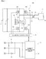
- Fig. 1 is a diagram for explaining a current measurement system 100 including a current detection device 1 according to the first embodiment.
- the current measurement system 100 includes a current detection device 1, a power feed unit 2 including a load 21 that receives power supply from a DC power supply 11, and a current determination unit 3 that rectifies a current detected by the current detection device 1 and determines a value of the current.
- the current determination unit 3 determines the value of the current detected by the current detection device 1, and controls a switching element of the current detection device 1.
- the current determination unit 3 may stop or start driving the current detection device 1 in accordance with a result of the determination.
- the current detection device 1 includes a current path 16 as a first current path through which the first current ia flows, and a current path 17 as a second current path through which a second current ib flows.
- the current detection device 1 further includes switching elements 131, 132, 133, and 134 that switch between the current path 16 and the current path 17 and allow the first current ia and the second current ib to flow alternately, and a common coil section 151 through which an induction current flows by the first current ia and the second current ib.
- the coil section 151 is a coil part of a current transformer 15, and a detection signal is output from output terminals A and C of the coil section 151 by induced electromotive force generated in the coil section 151.
- the switching elements 132 and 133 configure a first transistor pair including two transistor elements that allow the first current ia to flow through the current path 16.
- the switching elements 131 and 134 configure a second transistor pair including two transistor elements that allow the second current ib to flow through the current path 17.
- the switching elements 131 to 134 configure a full-bridge circuit, and the current paths 16 and 17 each become an arm of the full-bridge circuit.
- the first current ia flowing through the current path 16 and the second current ib flowing through the current path 17 are arm currents of the full-bridge circuit.
- the switching elements 132 and 133 are turned on at the same time while the switching elements 131 and 134 are turned off. Meanwhile, a flow path of a current (current path) from the switching element 132 to a coil end 171, a coil 19, a coil end 161, and the switching element 133 is formed in the current detection device 1. A part of this current path between the switching elements 132 and 133 is defined as the current path 16. In this state, the current flowing out of the current detection device 1 flows between a source and a drain of the switching element 132 and flows into the current path 17. The current flowing into the current path 17 becomes the first current ia from the coil end 171 through the coil 19, and returns to the current detection device 1 through the source and the drain of the switching element 133.
- the switching elements 131 and 134 are turned on at the same time while the switching elements 132 and 133 are turned off. Meanwhile, a current path from the switching element 131 to the coil end 161, the coil 19, the coil end 171, and the switching element 134 is formed in the current detection device 1. A part of this current path between the switching elements 131 and 134 is defined as the current path 17.
- the current flowing out of the current detection device 1 flows between a source and a drain of the switching element 131, and further flows from the coil 19 to a turn current path 170 through the coil end 171.
- the current flowing into the turn current path 170 becomes the second current ib and returns to the DC power supply 11 through the source and the drain of the switching element 134.
- the coil section 151 generates an induction current by a current flowing between the two switching elements 132 and 133 or between the two switching elements 131 and 134.
- the current detection device 1 further includes the DC power supply 11 and a full-bridge control circuit 18 that controls the switching elements 131 to 134 by applying a voltage to gates of the switching elements 131 to 134.
- the full-bridge control circuit 18 controls the switching elements 132 and 133 to be turned on at the same time, and controls the switching elements 131 and 134 to be turned off during this time. Meanwhile, a current path from the DC power supply 11 to a current path 16 and from the switching element 133 on the current path 16 back to the DC power supply 11 are formed in the current detection device 1 as described above.
- the full-bridge control circuit 18 controls the switching elements 131 and 134 to be turned on at the same time, and controls the switching elements 132 and 133 to be turned off during this time. Meanwhile, a current path from the DC power supply 11 to a current path 17 and from the switching element 134 on the current path 17 back to the DC power supply 11 are formed in the current detection device 1 as described above.
- This full-bridge control circuit 18 may use a small computer such as a microcomputer.
- the coil section 151 includes an output terminal B in addition to the output terminals A and C, which are a total of three output terminals A, B, and C.
- the output terminal B among these output terminals is a center tap that is drawn out of the coil section 151 in a middle of the coil section 151.
- the coil section 151 operates like two half-wave circuits, and the current flowing through the coil section 151 is full-wave rectified.
- this full-wave rectification allows the first current ia and the second current ib to be detected at the respective positive-side peak values, and allows both the first current ia and the second current ib to be determined at one determination reference value in a current determination circuit.
- the first embodiment further includes a current alternation unit that alternates the induction current flowing through the coil section 151 by the first current ia and the induction current flowing through the coil section 151 by the second current ib.
- alternating the induction current means flowing the induction current generated in the coil section 151 by the induced electromotive force such that flow directions are reversed at a constant cycle.
- the induction current flows to the coil section 151 when the first current ia and the second current ib which are DC currents flow or disappear (hereinafter, referred to as "turn-on or turn-off of the first current ia and turn-on or turn-off of the second current ib").
- Such an induction current is represented by a waveform having a cycle corresponding to the turn-on or turn-off of the first current ia and the second current ib.
- a phase of a first induction current ia i flowing through the coil section 151 by the first current ia and a phase of a second induction current ib i flowing through the coil section 151 by the second current ib are inverted ( Fig. 3 ).
- the current detection device 1 includes the turn current path 170 in which the second current ib flows in the current path 17 in a direction opposite to the flow direction of the first current ia.
- An induction current is generated in the coil section 151 by the current flowing through the turn current path 170.
- the first induction current ia i and the second induction current ib i alternate with each other by reversing the flow directions of the first current ia and the second current ib.
- the turn current path 170 thus functions as a current alternation unit in the first embodiment.
- an AC current is generated from the first current ia and the second current ib which are DC currents by alternately turning on and off the switching elements 132 and 133 and the switching elements 131 and 134.
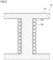
- Fig. 2 is a schematic diagram for explaining the coil section 151, and illustrates a longitudinal section of the coil section 151 only on a secondary side.
- the coil section 151 shown in Fig. 2 uses a core 150 having a middle leg. Examples of such a core are cores having an EI shape and an ER shape.
- the coil section 151 includes a core 150 such as an iron core, and a first coil 152 and a second coil 153 wound around the core 150.
- the first coil 152 and the second coil 153 are bifilar-wound around one core 150.
- the first coil 152 and the second coil 153 are distinguished from each other by inclinations of the hatching lines in the section.
- Bifilar-winding refers to winding two conductive wires side by side in a length direction of the core 150 as shown in Fig. 2 .
- the two conductive wires may be twisted and then wound.
- the bifilar-wound coil section 151 has good coupling between the coils, reduced leakage inductance, and a low operating impedance.
- This coil section 151 has a configuration suitable for the current transformer 15 that measures the current flowing alternately through the two current paths 16 and 17.
- the power feed unit 2 includes a coil 19 having one coil end 161 connected to the current path 16 and the other coil end 171 connected to the current path 17, and a coil 20 separated from the coil 19.
- the coil 19 and the coil 20 configure an insulating transformer, and an induced electromotive force is generated in the coil 19 by the first current ia or the second current ib flowing through the coil 19.
- the induced electromotive force generated in the coil 19 is supplied to the load 21.
- the load 21 may be a cell motor, an air conditioner, a car navigation device, or the like.
- the current determination unit 3 is connected to the output terminals A, B, and C of the coil section 151. Further, the current determination unit 3 includes a current determination circuit 33 that determines the current supplied to the power feed unit 2 by the first induction current ia i and the second induction current ib i input from the output terminals A and C.
- a diode 31 is provided between the output terminal A and the current determination circuit 33, and a diode 32 is provided between the output terminal C and the current determination circuit 33.
- Each of the diodes 31 and 32 allows a current to flow in a direction toward the current determination circuit 33.
- the first induction current ia i output from the output terminal A and the second induction current ib i output from the output terminal C are combined and input to the current determination circuit 33.
- Fig. 3A is a schematic diagram illustrating the first induction current ia i .
- Fig. 3B is a schematic diagram illustrating the second induction current ib i .
- the first induction current ia i and the second induction current ib i have waveforms whose phases are opposite to each other and are equal in amplitude with respect to a potential of the output terminal B.
- Fig. 3C is a diagram showing a composite waveform of the first induction current ia i and the second induction current ib i .
- the current determination circuit 33 detects a value of the current output in a positive direction of the composite waveform (hereinafter also referred to as "high current side") shown in Fig. 3C . Then, the detected value is output to the full-bridge control circuit 18.
- the full-bridge control circuit 18 may turn on and turn off the switching elements 132 and 133 and the switching elements 131 and 134 on the basis of, for example, timing of inputting a signal representing the detected value. Further, the full-bridge control circuit 18 may determine the values of the first current ia and the second current ib from the detected value on the high current side, and may determine an amount and abnormality of a supply current. At this time, the full-bridge control circuit 18 may turn off all of the switching elements 131 to 134 to stop the supply of the first current ia and the second current ib to the load 21.
- the values of the first current ia and the second current ib can be determined, for example, by associating the values of the first current ia and the second current ib in advance with the values of the first induction current ia i and the second induction current ib i generated by the first current ia and the second current ib, respectively.
- the current determination circuit 33 may store in advance the values of the first induction current ia i and the second induced current ib i corresponding to the threshold values of the first current ia and the second current ib determined to be abnormal, and the switching elements 131 to 134 may be turned off when the values of the first induction current ia i and the second induction current ib i are above or below the threshold values.
- the current determination circuit 33 may output the detected value to the outside, and an external calculation device (not shown in the drawings) may calculate the detected value on the high current side, the current supplied to the coil 19, and the power supplied to the load 21.
- the detected value detected by the current determination circuit 33 is used for, for example, constant current control or over current protection (OCP) control of the current detection device 1.
- OCP over current protection
- the full-bridge control circuit 18 turns on the switching elements 132 and 133 and turns off the switching elements 131 and 134. At this time, the current flowing from the DC power supply 11 passes through the current path 16 as the first current ia, and induces the first induction current ia i in the coil section 151.
- the full-bridge control circuit 18 turns on the switching elements 131 and 134 and turns off the switching elements 132 and 133.
- the current flowing out of the DC power supply 11 passes through the current path 17 as the second current ib having an opposite flow direction, and induces the second induction current ib i in the coil section 151.
- the first induction current ia i and the second induction current ib i are output from the output terminal A or the output terminal C.
- the first induction current ia i and the second induction current ib i that have been output are merged and input to the current determination circuit 33.
- the phases of the first induction current ia i flowing through the current path 16 and the second induction current ib i flowing through the current path 17 can be reversed by inverting one of the currents flowing through the current paths 16 and 17 with respect to the other current. Then, the values of the first induction current ia i and the second induction current ib i on the high current side can be detected from the waveform obtained by combining the first induction current ia i and the second induction current ib i .
- both the first current ia and the second current ib can be measured by the common current transformer 15.
- This configuration can reduce the number of current transformers as compared with the configuration of Japanese Laid-open patent publication No. 2010-41814 in which the first current ia and the second current ib are measured by different current transformers.
- the current transformer which includes a coil, has a relatively large installation space, and reducing the number of current transformers is advantageous for downsizing the entire device.
- a compact device can shorten a length of the wiring routed in the device.
- the wiring is thus hardly affected by a surge current or noise, thereby enhancing the signal quality and the driving reliability.
- the current on the primary side is doubled compared to a configuration in which the first current ia and the second current ib are measured by different current transformers.
- the first embodiment allows use of the coil section 151 having the same core size and the same number of windings as in the case where two current transformers are used for the current transformer 15 by alternating the first current ia and the second current ib.
- the bifilar-winding of the coil section 151 of one current transformer 15 allows a favorable detection of the current flowing through the two current paths 16 and 17 with one coil and the same level of measurement accuracy as in the configuration where the currents are measured by different current transformers.
- only one current determination circuit 33 is sufficient, which is more advantageous for downsizing the device.
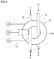
- Fig. 4 is a diagram for explaining the second embodiment, and is a schematic diagram illustrating an upper surface 45a of a toroidal coil 45.
- the second embodiment is different from the first embodiment using a core 150 having the middle leg in that the coil section 151 is the toroidal coil 45 having a toroidal core (not shown in the drawings).
- the toroidal core is a doughnut-shaped core in which a ferromagnetic material having a rectangular belt shape in a longitudinal section is formed in an annular shape with a starting end and a terminal end coincident with each other. Examples of the ferromagnetic material include iron, nickel, cobalt, and alloys thereof.
- the toroidal coil 45 has an annular shape as viewed from above, and Fig. 4 shows one surface having an annular shape (for example, the upper surface 45a).
- an annular surface that is a reverse surface of the upper surface 45a (not shown in the drawings) is referred to as the other surface.
- the current paths 16 and 17 are inserted through the toroidal coil 45.
- the current path 17 does not have the turn current path 170, and instead the current path 17 is inserted from the upper surface 45a toward the other surface in a top view of the toroidal coil 45.
- the current path 16 is inserted from the other surface toward the upper surface 45a.
- the toroidal coil 45 is fixed at a part between the switching elements 131 and 133 of the current path 16 and a part between the switching elements 132 and 134 of the current path 17.
- a first current ic and a second current id flowing in the same direction are supplied to the current path 16 and the current path 17, respectively.
- This configuration allows the first current ic and the second current id flowing in the opposite directions to alternately flow in an annular part of the toroidal coil 45.
- the induction current generated in the coil section 151 by the first current ic and the second current id is an alternating current.
- the toroidal coil 45, the current path 17 inserted through the toroidal coil 45 from the upper surface 45a toward the other surface, and the current path 16 inserted from the other surface toward the upper surface 45a functions as a current alternation unit.
- the first current ic and the second current id can be measured by attaching one toroidal coil 45 to the existing current paths. Further, bifilar-winding is possible in the toroidal coil 45 by arranging two conductive wires side by side or twisting the two conductive wires, and winding the twisted conductive wires around the toroidal core. As a result, in the second embodiment, similarly to the first embodiment, the current in the two current paths 16 and 17 can be accurately measured using one toroidal coil 45.
- the switching elements include the switching elements 132 and 133 that allow the first current ia to flow through the current path 16 and the switching elements 131 and 134 that allow the second current ib to flow through the current path 17.
- the coil section 151 generates an electromotive force by a current flowing upstream or downstream of the switching elements 132 and 133 and the switching elements 131 and 134.
- the current transformer 15 does not necessarily measure the current between the switching element 132 and the switching element 133 or between the switching element 131 and the switching element 134. The current is measured at any location in the current paths 16 and 17.
- Fig. 5A illustrates an example in which the coil section 151 generates an induction current by a current upstream of the switching elements 132 and 133 and the switching elements 131 and 134 in the current detection device 1 according to the first embodiment.
- the current transformer 15 shown in Fig. 5A is provided upstream of the switching element 131, and the current path 17 configures the turn current path 170 upstream of the switching element 133.
- the coil end 161 is connected between the switching element 131 and the switching element 134, and the coil end 171 is connected between the switching element 132 and the switching element 133 to supply current to the coil 19.
- the full-bridge control circuit 18 alternately turns on and off a pair of the switching elements 131 and 133 and a pair of the switching elements 132 and 134, similarly to the first embodiment.
- Fig. 5B illustrates an example in which the toroidal coil 45 according to the second embodiment is provided upstream of the switching elements 132 and 133 and the switching elements 131 and 134.
- the toroidal coil 45 and the current paths 16 ad 17 inserted through the toroidal coil 45 shown in Fig. 5B have a similar configuration to a configuration in the second embodiment.
- the toroidal coil 45 is provided between the DC power supply 11 and the switching element 131 and between the DC power supply 11 and the switching element 133.
- a current if immediately after flowing out of the DC power supply 11 branches into the current paths 16 and 17, and flows in and out as the first current ic and the second current id, respectively.
- Fig. 6A illustrates an example in which the coil section 151 generates an induction current by a current downstream of the switching elements 132 and 133 and the switching elements 131 and 134 in the current detection device 1 according to the first embodiment.
- the current transformer 15 shown in Fig. 6A is provided downstream of the switching element 132, and the current path 17 configures the turn current path 170 downstream of the switching element 134.
- Fig. 6B illustrates an example in which the toroidal coil 45 according to the second embodiment is provided downstream of the switching elements 132 and 133 and the switching elements 131 and 134.
- the toroidal coil 45 and the current paths 16 and 17 inserted through the toroidal coil 45 shown in Fig. 6B have a similar configuration to a configuration in the second embodiment.
- the toroidal coil 45 is provided between the switching element 132 and the DC power supply 11 and between the switching element 134 and the DC power supply 11.
- the first current ic and the second current id flow into the current paths 16 and 17, merge after flowing out, and flow into the DC power supply 11 as the current ie.
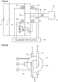
- Figs. 7A and 7B are diagrams illustrating a current detection device according to a second modification.
- the current detection device according to the first embodiment is applied to a push-pull circuit.
- Fig. 7A illustrates an example in which the current transformer 15 is provided upstream of the switching elements 131 and 132.
- Fig. 7B illustrates an example in which the current transformer 15 is provided downstream of the switching elements 131 and 132.
- a push-pull control circuit 28 alternately turns on and off the switching elements 131 and 132.
- the DC current supplied from the DC power supply 11 flows alternately into the current path 16 and the current path 17, and the first induction current generated in the coil section 151 is output from the output terminals A and C.
- the coil 46 is connected to the current path 16, and the coil 47 separated from the coil 46 is connected to the current path 17.
- a current in the same direction as the first current ia is alternately supplied to the coils 46 and 47.
- currents in different directions alternately flow through the coils 46 and 47, and a current flowing through the coil 20 in the same direction as the coil 47 is generated by electromagnetic induction.
- the induced electromotive force generated in the coil 20 is supplied to the load 21.
- the embodiment includes the following technical idea.
Landscapes
- Engineering & Computer Science (AREA)
- Power Engineering (AREA)
- Physics & Mathematics (AREA)
- General Physics & Mathematics (AREA)
- Measurement Of Current Or Voltage (AREA)
- Measuring Instrument Details And Bridges, And Automatic Balancing Devices (AREA)
- Inverter Devices (AREA)
Abstract
Description
- This application claims the benefits of Japanese Patent Applications No.
2019-133552 filed on July 19, 2019 - The present invention relates to a current detection device.
- From a viewpoint of power saving, various devices are provided with a power monitoring system. Examples of a power monitoring system that measures a current include a device called a current transformer (CT). A current transformer is a device that converts an AC current to be measured into a secondary current in accordance with a winding ratio of a coil. Such a current transformer is disclosed in, for example, Japanese Laid-open patent publication No.
2010-41814 2010-41814 - Patent Literature 1: Japanese Laid-open patent publication No.
2010-41814 - The power supply device disclosed in Japanese Laid-open patent publication No.
2010-41814 - The present invention has been made in view of the above, and relates to a current detection device advantageous for downsizing and capable of reducing a length of a routed wiring.
- According to the present invention, there is provided a current detection device comprising: a first current path through which a first current flows and a second current path through which a second current flows; a switching element that switches between the first current path and the second current path and allows the first current and the second current to flow alternately; a common coil section through which an induction current flows by the first current and the second current; and a current alternation unit that alternates the induction current flowing through the coil section by the first current and the induction current flowing through the coil section by the second current.
- The present invention can provide a current detection device that is advantageous for downsizing and has a reduced length of routed wiring.
- The above and other objects, advantages and features of the present invention will be more apparent from the following description of certain preferred embodiments taken in conjunction with the accompanying drawings, in which:
-
Fig. 1 is a diagram illustrating a current measurement system including a current detection device according to a first embodiment of the present invention; -
Fig. 2 is a schematic longitudinal sectional view of a coil section shown inFig. 1 ; -
Fig. 3A is a schematic diagram illustrating a first induction current;Fig. 3B is a schematic diagram illustrating a second induction current; andFig. 3C is a schematic diagram illustrating a composite of the first induction current and the second induction current; -
Fig. 4 is a diagram for explaining a second embodiment of the present invention, and is a schematic diagram illustrating an upper surface of a toroidal coil; -
Fig. 5A is a diagram for explaining a first modification of the first embodiment; andFig. 5B is a diagram for explaining a first modification of the second embodiment; -
Fig. 6A is another diagram for explaining a first modification of the first embodiment; andFig. 6B is another diagram for explaining the first modification of the second embodiment; -
Fig. 7A is a diagram for explaining a second modification of the first embodiment; andFig. 7B is another diagram for explaining the second modification of the first embodiment. - The invention will be now described herein with reference to illustrative embodiments. Those skilled in the art will recognize that many alternative embodiments can be accomplished using the teachings of the present invention and that the invention is not limited to the embodiments illustrated for explanatory purposed.
- Hereinafter, a first embodiment and a second embodiment of the present invention will be described. Both the first embodiment and the second embodiment show a technical idea and a configuration example of the present invention, and do not limit a specific configuration or a dimension and shape. Further, the drawings used in the first embodiment and the second embodiment mainly show the functions, arrangements, relationships among the members, and the like, and do not accurately show the dimensions, shape, aspect ratio, and the like.
-
Fig. 1 is a diagram for explaining acurrent measurement system 100 including a current detection device 1 according to the first embodiment. Thecurrent measurement system 100 includes a current detection device 1, apower feed unit 2 including aload 21 that receives power supply from aDC power supply 11, and acurrent determination unit 3 that rectifies a current detected by the current detection device 1 and determines a value of the current. Thecurrent determination unit 3 determines the value of the current detected by the current detection device 1, and controls a switching element of the current detection device 1. Thecurrent determination unit 3 may stop or start driving the current detection device 1 in accordance with a result of the determination. - The current detection device 1 includes a
current path 16 as a first current path through which the first current ia flows, and acurrent path 17 as a second current path through which a second current ib flows. The current detection device 1 further includesswitching elements current path 16 and thecurrent path 17 and allow the first current ia and the second current ib to flow alternately, and acommon coil section 151 through which an induction current flows by the first current ia and the second current ib. Thecoil section 151 is a coil part of acurrent transformer 15, and a detection signal is output from output terminals A and C of thecoil section 151 by induced electromotive force generated in thecoil section 151. - The
switching elements current path 16. Theswitching elements current path 17. Theswitching elements 131 to 134 configure a full-bridge circuit, and thecurrent paths current path 16 and the second current ib flowing through thecurrent path 17 are arm currents of the full-bridge circuit. - In such a full-bridge circuit, for example, the
switching elements switching elements switching element 132 to acoil end 171, acoil 19, acoil end 161, and theswitching element 133 is formed in the current detection device 1. A part of this current path between theswitching elements current path 16. In this state, the current flowing out of the current detection device 1 flows between a source and a drain of theswitching element 132 and flows into thecurrent path 17. The current flowing into thecurrent path 17 becomes the first current ia from thecoil end 171 through thecoil 19, and returns to the current detection device 1 through the source and the drain of theswitching element 133. - Next, in the first embodiment, the
switching elements switching elements switching element 131 to thecoil end 161, thecoil 19, thecoil end 171, and theswitching element 134 is formed in the current detection device 1. A part of this current path between theswitching elements current path 17. In this state, the current flowing out of the current detection device 1 flows between a source and a drain of theswitching element 131, and further flows from thecoil 19 to a turncurrent path 170 through thecoil end 171. The current flowing into the turncurrent path 170 becomes the second current ib and returns to theDC power supply 11 through the source and the drain of theswitching element 134. - The
coil section 151 generates an induction current by a current flowing between the two switchingelements elements - The current detection device 1 further includes the
DC power supply 11 and a full-bridge control circuit 18 that controls the switchingelements 131 to 134 by applying a voltage to gates of the switchingelements 131 to 134. The full-bridge control circuit 18 controls the switchingelements elements DC power supply 11 to acurrent path 16 and from the switchingelement 133 on thecurrent path 16 back to theDC power supply 11 are formed in the current detection device 1 as described above. - The full-
bridge control circuit 18 controls the switchingelements elements DC power supply 11 to acurrent path 17 and from the switchingelement 134 on thecurrent path 17 back to theDC power supply 11 are formed in the current detection device 1 as described above. - This full-
bridge control circuit 18 may use a small computer such as a microcomputer. - In the first embodiment, the
coil section 151 includes an output terminal B in addition to the output terminals A and C, which are a total of three output terminals A, B, and C. The output terminal B among these output terminals is a center tap that is drawn out of thecoil section 151 in a middle of thecoil section 151. When the center tap is provided in thecoil section 151, thecoil section 151 operates like two half-wave circuits, and the current flowing through thecoil section 151 is full-wave rectified. In the first embodiment, this full-wave rectification allows the first current ia and the second current ib to be detected at the respective positive-side peak values, and allows both the first current ia and the second current ib to be determined at one determination reference value in a current determination circuit. - The first embodiment further includes a current alternation unit that alternates the induction current flowing through the
coil section 151 by the first current ia and the induction current flowing through thecoil section 151 by the second current ib. Here, "alternating the induction current" means flowing the induction current generated in thecoil section 151 by the induced electromotive force such that flow directions are reversed at a constant cycle. The induction current flows to thecoil section 151 when the first current ia and the second current ib which are DC currents flow or disappear (hereinafter, referred to as "turn-on or turn-off of the first current ia and turn-on or turn-off of the second current ib"). Such an induction current is represented by a waveform having a cycle corresponding to the turn-on or turn-off of the first current ia and the second current ib. In the first embodiment, since the flow directions of the first current ia and the second current ib are reversed, a phase of a first induction current iai flowing through thecoil section 151 by the first current ia and a phase of a second induction current ibi flowing through thecoil section 151 by the second current ib are inverted (Fig. 3 ). - As shown in
Fig. 1 , the current detection device 1 according to the first embodiment includes the turncurrent path 170 in which the second current ib flows in thecurrent path 17 in a direction opposite to the flow direction of the first current ia. An induction current is generated in thecoil section 151 by the current flowing through the turncurrent path 170. As described above, the first induction current iai and the second induction current ibi alternate with each other by reversing the flow directions of the first current ia and the second current ib. The turncurrent path 170 thus functions as a current alternation unit in the first embodiment. In other words, in the first embodiment, an AC current is generated from the first current ia and the second current ib which are DC currents by alternately turning on and off the switchingelements elements -
Fig. 2 is a schematic diagram for explaining thecoil section 151, and illustrates a longitudinal section of thecoil section 151 only on a secondary side. Thecoil section 151 shown inFig. 2 uses acore 150 having a middle leg. Examples of such a core are cores having an EI shape and an ER shape. Thecoil section 151 includes a core 150 such as an iron core, and afirst coil 152 and asecond coil 153 wound around thecore 150. Thefirst coil 152 and thesecond coil 153 are bifilar-wound around onecore 150. InFig. 2 , thefirst coil 152 and thesecond coil 153 are distinguished from each other by inclinations of the hatching lines in the section. - Bifilar-winding refers to winding two conductive wires side by side in a length direction of the core 150 as shown in
Fig. 2 . In the bifilar-winding, the two conductive wires may be twisted and then wound. - The bifilar-
wound coil section 151 has good coupling between the coils, reduced leakage inductance, and a low operating impedance. Thiscoil section 151 has a configuration suitable for thecurrent transformer 15 that measures the current flowing alternately through the twocurrent paths - The
power feed unit 2 includes acoil 19 having onecoil end 161 connected to thecurrent path 16 and theother coil end 171 connected to thecurrent path 17, and acoil 20 separated from thecoil 19. Thecoil 19 and thecoil 20 configure an insulating transformer, and an induced electromotive force is generated in thecoil 19 by the first current ia or the second current ib flowing through thecoil 19. The induced electromotive force generated in thecoil 19 is supplied to theload 21. When thecurrent measurement system 100 is applied to, for example, an in-vehicle device, theload 21 may be a cell motor, an air conditioner, a car navigation device, or the like. - The
current determination unit 3 is connected to the output terminals A, B, and C of thecoil section 151. Further, thecurrent determination unit 3 includes acurrent determination circuit 33 that determines the current supplied to thepower feed unit 2 by the first induction current iai and the second induction current ibi input from the output terminals A andC. A diode 31 is provided between the output terminal A and thecurrent determination circuit 33, and adiode 32 is provided between the output terminal C and thecurrent determination circuit 33. Each of thediodes current determination circuit 33. The first induction current iai output from the output terminal A and the second induction current ibi output from the output terminal C are combined and input to thecurrent determination circuit 33. -
Fig. 3A is a schematic diagram illustrating the first induction current iai.Fig. 3B is a schematic diagram illustrating the second induction current ibi. As shown inFigs. 3A and 3B , the first induction current iai and the second induction current ibi have waveforms whose phases are opposite to each other and are equal in amplitude with respect to a potential of the output terminal B.Fig. 3C is a diagram showing a composite waveform of the first induction current iai and the second induction current ibi. - The
current determination circuit 33 detects a value of the current output in a positive direction of the composite waveform (hereinafter also referred to as "high current side") shown inFig. 3C . Then, the detected value is output to the full-bridge control circuit 18. The full-bridge control circuit 18 may turn on and turn off the switchingelements elements bridge control circuit 18 may determine the values of the first current ia and the second current ib from the detected value on the high current side, and may determine an amount and abnormality of a supply current. At this time, the full-bridge control circuit 18 may turn off all of the switchingelements 131 to 134 to stop the supply of the first current ia and the second current ib to theload 21. - The values of the first current ia and the second current ib can be determined, for example, by associating the values of the first current ia and the second current ib in advance with the values of the first induction current iai and the second induction current ibi generated by the first current ia and the second current ib, respectively. The
current determination circuit 33 may store in advance the values of the first induction current iai and the second induced current ibi corresponding to the threshold values of the first current ia and the second current ib determined to be abnormal, and the switchingelements 131 to 134 may be turned off when the values of the first induction current iai and the second induction current ibi are above or below the threshold values. - Further, the
current determination circuit 33 may output the detected value to the outside, and an external calculation device (not shown in the drawings) may calculate the detected value on the high current side, the current supplied to thecoil 19, and the power supplied to theload 21. The detected value detected by thecurrent determination circuit 33 is used for, for example, constant current control or over current protection (OCP) control of the current detection device 1. - Next, the overall operation of the
current measurement system 100 will be described. In the current detection device 1, first, the full-bridge control circuit 18 turns on the switchingelements elements DC power supply 11 passes through thecurrent path 16 as the first current ia, and induces the first induction current iai in thecoil section 151. - Next, the full-
bridge control circuit 18 turns on the switchingelements elements DC power supply 11 passes through thecurrent path 17 as the second current ib having an opposite flow direction, and induces the second induction current ibi in thecoil section 151. As a result, the first induction current iai and the second induction current ibi are output from the output terminal A or the output terminal C. - The first induction current iai and the second induction current ibi that have been output are merged and input to the
current determination circuit 33. In the first embodiment, the phases of the first induction current iai flowing through thecurrent path 16 and the second induction current ibi flowing through thecurrent path 17 can be reversed by inverting one of the currents flowing through thecurrent paths - According to the first embodiment, both the first current ia and the second current ib can be measured by the common
current transformer 15. This configuration can reduce the number of current transformers as compared with the configuration of Japanese Laid-open patent publication No.2010-41814 - A compact device can shorten a length of the wiring routed in the device. In the first embodiment, the wiring is thus hardly affected by a surge current or noise, thereby enhancing the signal quality and the driving reliability.
- In the first embodiment, the current on the primary side is doubled compared to a configuration in which the first current ia and the second current ib are measured by different current transformers. However, the first embodiment allows use of the
coil section 151 having the same core size and the same number of windings as in the case where two current transformers are used for thecurrent transformer 15 by alternating the first current ia and the second current ib. - Further, in the first embodiment, the bifilar-winding of the
coil section 151 of onecurrent transformer 15 allows a favorable detection of the current flowing through the twocurrent paths current measurement system 100 including onecurrent transformer 15, only onecurrent determination circuit 33 is sufficient, which is more advantageous for downsizing the device. - Next, a second embodiment of the present invention will be described.
-
Fig. 4 is a diagram for explaining the second embodiment, and is a schematic diagram illustrating anupper surface 45a of atoroidal coil 45. The second embodiment is different from the first embodiment using acore 150 having the middle leg in that thecoil section 151 is thetoroidal coil 45 having a toroidal core (not shown in the drawings). The toroidal core is a doughnut-shaped core in which a ferromagnetic material having a rectangular belt shape in a longitudinal section is formed in an annular shape with a starting end and a terminal end coincident with each other. Examples of the ferromagnetic material include iron, nickel, cobalt, and alloys thereof. - As shown in
Fig. 4 , thetoroidal coil 45 has an annular shape as viewed from above, andFig. 4 shows one surface having an annular shape (for example, theupper surface 45a). Here, an annular surface that is a reverse surface of theupper surface 45a (not shown in the drawings) is referred to as the other surface. Thecurrent paths toroidal coil 45. In the second embodiment, thecurrent path 17 does not have the turncurrent path 170, and instead thecurrent path 17 is inserted from theupper surface 45a toward the other surface in a top view of thetoroidal coil 45. Thecurrent path 16 is inserted from the other surface toward theupper surface 45a. - The
toroidal coil 45 is fixed at a part between the switchingelements current path 16 and a part between the switchingelements current path 17. A first current ic and a second current id flowing in the same direction are supplied to thecurrent path 16 and thecurrent path 17, respectively. - This configuration allows the first current ic and the second current id flowing in the opposite directions to alternately flow in an annular part of the
toroidal coil 45. The induction current generated in thecoil section 151 by the first current ic and the second current id is an alternating current. In other words, in the second embodiment, thetoroidal coil 45, thecurrent path 17 inserted through thetoroidal coil 45 from theupper surface 45a toward the other surface, and thecurrent path 16 inserted from the other surface toward theupper surface 45a functions as a current alternation unit. - In the second embodiment described above, the first current ic and the second current id can be measured by attaching one
toroidal coil 45 to the existing current paths. Further, bifilar-winding is possible in thetoroidal coil 45 by arranging two conductive wires side by side or twisting the two conductive wires, and winding the twisted conductive wires around the toroidal core. As a result, in the second embodiment, similarly to the first embodiment, the current in the twocurrent paths toroidal coil 45. - Next, a first modification and a second modification of the above first embodiment and second embodiment will be described.
- In the first modification, the switching elements include the switching
elements current path 16 and the switchingelements current path 17. Thecoil section 151 generates an electromotive force by a current flowing upstream or downstream of the switchingelements elements current transformer 15 does not necessarily measure the current between the switchingelement 132 and theswitching element 133 or between the switchingelement 131 and theswitching element 134. The current is measured at any location in thecurrent paths -
Fig. 5A illustrates an example in which thecoil section 151 generates an induction current by a current upstream of the switchingelements elements current transformer 15 shown inFig. 5A is provided upstream of theswitching element 131, and thecurrent path 17 configures the turncurrent path 170 upstream of theswitching element 133. - In the current detection device shown in
Fig. 5A , as in the first embodiment, thecoil end 161 is connected between the switchingelement 131 and theswitching element 134, and thecoil end 171 is connected between the switchingelement 132 and theswitching element 133 to supply current to thecoil 19. Further, the full-bridge control circuit 18 alternately turns on and off a pair of the switchingelements elements -
Fig. 5B illustrates an example in which thetoroidal coil 45 according to the second embodiment is provided upstream of the switchingelements elements toroidal coil 45 and thecurrent paths 16ad 17 inserted through thetoroidal coil 45 shown inFig. 5B have a similar configuration to a configuration in the second embodiment. However, in the example shown inFig. 5B , thetoroidal coil 45 is provided between theDC power supply 11 and theswitching element 131 and between theDC power supply 11 and theswitching element 133. Thus, a current if immediately after flowing out of theDC power supply 11 branches into thecurrent paths -
Fig. 6A illustrates an example in which thecoil section 151 generates an induction current by a current downstream of the switchingelements elements current transformer 15 shown inFig. 6A is provided downstream of theswitching element 132, and thecurrent path 17 configures the turncurrent path 170 downstream of theswitching element 134. -
Fig. 6B illustrates an example in which thetoroidal coil 45 according to the second embodiment is provided downstream of the switchingelements elements toroidal coil 45 and thecurrent paths toroidal coil 45 shown inFig. 6B have a similar configuration to a configuration in the second embodiment. However, in the example shown inFig. 6B , thetoroidal coil 45 is provided between the switchingelement 132 and theDC power supply 11 and between the switchingelement 134 and theDC power supply 11. As a result, the first current ic and the second current id flow into thecurrent paths DC power supply 11 as the current ie. - Next, a second modification of the first embodiment will be described.
-
Figs. 7A and 7B are diagrams illustrating a current detection device according to a second modification. In the second modification, the current detection device according to the first embodiment is applied to a push-pull circuit.Fig. 7A illustrates an example in which thecurrent transformer 15 is provided upstream of the switchingelements Fig. 7B illustrates an example in which thecurrent transformer 15 is provided downstream of the switchingelements Figs. 7A and 7B , a push-pull control circuit 28 alternately turns on and off the switchingelements DC power supply 11 flows alternately into thecurrent path 16 and thecurrent path 17, and the first induction current generated in thecoil section 151 is output from the output terminals A and C. - In the current detection device 1 shown in
Fig. 7A and 7B , thecoil 46 is connected to thecurrent path 16, and thecoil 47 separated from thecoil 46 is connected to thecurrent path 17. A current in the same direction as the first current ia is alternately supplied to thecoils coils coil 20 in the same direction as thecoil 47 is generated by electromagnetic induction. The induced electromotive force generated in thecoil 20 is supplied to theload 21. - The embodiment includes the following technical idea.
- (1) A current detection device comprising:
- a first current path through which a first current flows and a second current path through which a second current flows;
- a switching element that switches between the first current path and the second current path and allows the first current and the second current to flow alternately;
- a common coil section through which an induction current flows by the first current and the second current; and
- a current alternation unit that alternates the induction current flowing through the coil section by the first current and the induction current flowing through the coil section by the second current.
- (2) The current detection device according to (1),
in which the coil section includes a first coil and a second coil, and
the first coil and the second coil are bifilar-wound around one core. - (3) The current detection device according to (1) or (2),
in which the switching element includes a first transistor pair including two transistor elements that allow the first current to flow through the first current path, and a second transistor pair including two transistor elements that allow the second current to flow through the second current path, and
the coil section generates an induction current by a current flowing between the two transistor elements included in the first transistor pair or between the two transistor elements included in the second transistor pair. - (4) The current detection device according to (1) or (2),
in which the switching element includes a first transistor pair including two transistor elements that allow the first current to flow through the first current path, and a second transistor pair including two transistor elements that allow the second current to flow through the second current path, and
the coil section generates an electromotive force by a current flowing upstream or downstream of the first transistor pair and the second transistor pair. - (5) The current detection device according to any one of (1) to (4),
in which the current alternation unit includes a turn current path through which the second current flows in the second current path in a direction opposite to a flow direction of the first current, and
the coil section generates an induction current by a current flowing through the turn current path. - (6) The current detection device according to any one of (1) to (5),
in which the coil section is wound around a toroidal core and configure a toroidal coil, and
the current alternation unit includes the first current path inserted from one surface through another surface having an annular shape in a top view of the toroidal coil, and the second current path inserted from the other surface toward the one surface. - (7) The current detection device according to any one of (1) to (6),
in which a center tap is drawn from the coil section.
Claims (7)
- A current detection device comprising:a first current path through which a first current flows and a second current path through which a second current flows;a switching element that switches between the first current path and the second current path and allows the first current and the second current to flow alternately;a common coil section through which an induction current flows by the first current and the second current; anda current alternation unit that alternates the induction current flowing through the coil section by the first current and the induction current flowing through the coil section by the second current.
- The current detection device according to claim 1,
wherein the coil section includes a first coil and a second coil, and
the first coil and the second coil are bifilar-wound around one core. - The current detection device according to claim 1 or 2,
wherein the switching element includes a first transistor pair including two transistor elements that allow the first current to flow through the first current path, and a second transistor pair including two transistor elements that allow the second current to flow through the second current path, and
the coil section generates an induction current by a current flowing between the two transistor elements included in the first transistor pair or between the two transistor elements included in the second transistor pair. - The current detection device according to claim 1 or 2,
wherein the switching element includes a first transistor pair including two transistor elements that flow the first current through the first current path, and a second transistor pair including two transistor elements that flow the second current through the second current path, and
the coil section generates an electromotive force by a current flowing upstream or downstream of the first transistor pair and the second transistor pair. - The current detection device according to any one of claims 1 to 4,
wherein the current alternation unit includes a turn current path through which the second current flows in the second current path in a direction opposite to a flow direction of the first current, and
the coil section generates an induction current by a current flowing through the turn current path. - The current detection device according to any one of claims 1 to 5,
wherein the coil section is wound around a toroidal core and configure a toroidal coil, and
the current alternation unit includes the first current path inserted from one surface through another surface having an annular shape in a top view of the toroidal coil, and the second current path inserted from the other surface toward the one surface. - The current detection device according to any one of claims 1 to 6,
wherein a center tap is drawn from the coil section.
Applications Claiming Priority (1)
| Application Number | Priority Date | Filing Date | Title |
|---|---|---|---|
| JP2019133552A JP7358812B2 (en) | 2019-07-19 | 2019-07-19 | current detection device |
Publications (1)
| Publication Number | Publication Date |
|---|---|
| EP3767816A1 true EP3767816A1 (en) | 2021-01-20 |
Family
ID=71452135
Family Applications (1)
| Application Number | Title | Priority Date | Filing Date |
|---|---|---|---|
| EP20183678.0A Ceased EP3767816A1 (en) | 2019-07-19 | 2020-07-02 | Current detection device |
Country Status (4)
| Country | Link |
|---|---|
| US (1) | US11340267B2 (en) |
| EP (1) | EP3767816A1 (en) |
| JP (1) | JP7358812B2 (en) |
| CN (1) | CN112240951B (en) |
Cited By (1)
| Publication number | Priority date | Publication date | Assignee | Title |
|---|---|---|---|---|
| EP4184770A1 (en) * | 2021-11-23 | 2023-05-24 | Tridonic GmbH & Co. KG | An isolated switched resonant converter |
Families Citing this family (1)
| Publication number | Priority date | Publication date | Assignee | Title |
|---|---|---|---|---|
| CN114587674A (en) * | 2022-04-15 | 2022-06-07 | 东莞市因范生活科技有限公司 | A method of starting an electric toothbrush without a button |
Citations (3)
| Publication number | Priority date | Publication date | Assignee | Title |
|---|---|---|---|---|
| US5315498A (en) * | 1992-12-23 | 1994-05-24 | International Business Machines Corporation | Apparatus providing leading leg current sensing for control of full bridge power supply |
| EP0631145A2 (en) * | 1993-06-24 | 1994-12-28 | DEUTRONIC ELEKTRONIK GmbH | Current measuring method and device for bridge circuits |
| JP2010041814A (en) | 2008-08-05 | 2010-02-18 | Toyota Industries Corp | Power supply device |
Family Cites Families (7)
| Publication number | Priority date | Publication date | Assignee | Title |
|---|---|---|---|---|
| US4542440A (en) | 1983-11-02 | 1985-09-17 | Sundstrand Corporation | Switch current sensing with snubber current suppression in a push-pull converter |
| JP3332117B2 (en) * | 1994-05-16 | 2002-10-07 | ケイディーディーアイ株式会社 | DC current detector |
| JP3959077B2 (en) * | 2004-06-30 | 2007-08-15 | Tdk株式会社 | Parallel drive power supply |
| JP2010022125A (en) * | 2008-07-10 | 2010-01-28 | Cosel Co Ltd | Multi-phase power-factor improving circuit |
| JP6409668B2 (en) * | 2015-04-21 | 2018-10-24 | 株式会社デンソー | Trance |
| JP2018200242A (en) * | 2017-05-29 | 2018-12-20 | 株式会社トーキン | Current sensor |
| EP3736941B1 (en) * | 2019-05-08 | 2022-11-30 | Delta Electronics (Thailand) Public Co., Ltd. | Wireless power transfer arrangement |
-
2019
- 2019-07-19 JP JP2019133552A patent/JP7358812B2/en active Active
-
2020
- 2020-07-02 EP EP20183678.0A patent/EP3767816A1/en not_active Ceased
- 2020-07-13 US US16/926,826 patent/US11340267B2/en active Active
- 2020-07-17 CN CN202010692612.7A patent/CN112240951B/en active Active
Patent Citations (3)
| Publication number | Priority date | Publication date | Assignee | Title |
|---|---|---|---|---|
| US5315498A (en) * | 1992-12-23 | 1994-05-24 | International Business Machines Corporation | Apparatus providing leading leg current sensing for control of full bridge power supply |
| EP0631145A2 (en) * | 1993-06-24 | 1994-12-28 | DEUTRONIC ELEKTRONIK GmbH | Current measuring method and device for bridge circuits |
| JP2010041814A (en) | 2008-08-05 | 2010-02-18 | Toyota Industries Corp | Power supply device |
Cited By (2)
| Publication number | Priority date | Publication date | Assignee | Title |
|---|---|---|---|---|
| EP4184770A1 (en) * | 2021-11-23 | 2023-05-24 | Tridonic GmbH & Co. KG | An isolated switched resonant converter |
| WO2023094213A1 (en) * | 2021-11-23 | 2023-06-01 | Tridonic Gmbh & Co Kg | An isolated switched resonant converter |
Also Published As
| Publication number | Publication date |
|---|---|
| US11340267B2 (en) | 2022-05-24 |
| JP2021019421A (en) | 2021-02-15 |
| JP7358812B2 (en) | 2023-10-11 |
| CN112240951A (en) | 2021-01-19 |
| US20210018539A1 (en) | 2021-01-21 |
| CN112240951B (en) | 2025-11-14 |
Similar Documents
| Publication | Publication Date | Title |
|---|---|---|
| JP2002010535A (en) | Non-contact power transmission device | |
| JP2006230032A (en) | Power transmitter and power transmissison method | |
| US7095629B2 (en) | Switching power supply circuit | |
| KR20050031968A (en) | Switching power supply circuit | |
| US9984817B2 (en) | Coil for wireless power transmission and wireless power transmission apparatus | |
| TWI282201B (en) | Power converter | |
| EP2827484B1 (en) | Dc-dc converter | |
| CN101404405B (en) | Creepage breaker | |
| US7522430B2 (en) | Switching power supply apparatus | |
| US11340267B2 (en) | Current detection device having a current transformer with a common coil section | |
| US20070115700A1 (en) | Transformer with current sensing means | |
| WO2012049818A1 (en) | Ac/dc converter | |
| KR20050085047A (en) | Switching power supply circuit | |
| CN111682771B (en) | Power supply device and medical system | |
| US20040190312A1 (en) | Switching power supply | |
| JP5255881B2 (en) | Non-contact power feeding device | |
| JP3356135B2 (en) | Mobile contactless power supply | |
| EP1783788A2 (en) | Transformer with current sensing means | |
| US10389264B2 (en) | Power converter | |
| JP4367611B2 (en) | Switching power supply circuit | |
| KR102346445B1 (en) | Power transforming apparatus and air conditioner including the same | |
| JPH0638523A (en) | Two-transistor power rectifier | |
| JP2004088952A (en) | Resonance-type switching power supply | |
| JP5372597B2 (en) | Circuit breaker for low-voltage power contract | |
| CN117767698A (en) | A power converter, its control method and energy storage system |
Legal Events
| Date | Code | Title | Description |
|---|---|---|---|
| PUAI | Public reference made under article 153(3) epc to a published international application that has entered the european phase |
Free format text: ORIGINAL CODE: 0009012 |
|
| STAA | Information on the status of an ep patent application or granted ep patent |
Free format text: STATUS: THE APPLICATION HAS BEEN PUBLISHED |
|
| AK | Designated contracting states |
Kind code of ref document: A1 Designated state(s): AL AT BE BG CH CY CZ DE DK EE ES FI FR GB GR HR HU IE IS IT LI LT LU LV MC MK MT NL NO PL PT RO RS SE SI SK SM TR |
|
| AX | Request for extension of the european patent |
Extension state: BA ME |
|
| STAA | Information on the status of an ep patent application or granted ep patent |
Free format text: STATUS: REQUEST FOR EXAMINATION WAS MADE |
|
| RAP3 | Party data changed (applicant data changed or rights of an application transferred) |
Owner name: SUMIDA CORPORATION |
|
| 17P | Request for examination filed |
Effective date: 20210427 |
|
| RBV | Designated contracting states (corrected) |
Designated state(s): AL AT BE BG CH CY CZ DE DK EE ES FI FR GB GR HR HU IE IS IT LI LT LU LV MC MK MT NL NO PL PT RO RS SE SI SK SM TR |
|
| STAA | Information on the status of an ep patent application or granted ep patent |
Free format text: STATUS: EXAMINATION IS IN PROGRESS |
|
| 17Q | First examination report despatched |
Effective date: 20220314 |
|
| STAA | Information on the status of an ep patent application or granted ep patent |
Free format text: STATUS: THE APPLICATION HAS BEEN REFUSED |
|
| 18R | Application refused |
Effective date: 20250218 |