EP3767797B1 - Rotor structure, permanent magnet auxiliary synchronous reluctance motor and electric vehicle - Google Patents
Rotor structure, permanent magnet auxiliary synchronous reluctance motor and electric vehicle Download PDFInfo
- Publication number
- EP3767797B1 EP3767797B1 EP18910127.2A EP18910127A EP3767797B1 EP 3767797 B1 EP3767797 B1 EP 3767797B1 EP 18910127 A EP18910127 A EP 18910127A EP 3767797 B1 EP3767797 B1 EP 3767797B1
- Authority
- EP
- European Patent Office
- Prior art keywords
- magnetic steel
- slot
- rotor body
- rotor
- outer layer
- Prior art date
- Legal status (The legal status is an assumption and is not a legal conclusion. Google has not performed a legal analysis and makes no representation as to the accuracy of the status listed.)
- Active
Links
Images




Classifications
-
- H—ELECTRICITY
- H02—GENERATION; CONVERSION OR DISTRIBUTION OF ELECTRIC POWER
- H02K—DYNAMO-ELECTRIC MACHINES
- H02K1/00—Details of the magnetic circuit
- H02K1/06—Details of the magnetic circuit characterised by the shape, form or construction
- H02K1/22—Rotating parts of the magnetic circuit
- H02K1/27—Rotor cores with permanent magnets
- H02K1/2706—Inner rotors
- H02K1/272—Inner rotors the magnetisation axis of the magnets being perpendicular to the rotor axis
- H02K1/274—Inner rotors the magnetisation axis of the magnets being perpendicular to the rotor axis the rotor consisting of two or more circumferentially positioned magnets
- H02K1/2753—Inner rotors the magnetisation axis of the magnets being perpendicular to the rotor axis the rotor consisting of two or more circumferentially positioned magnets the rotor consisting of magnets or groups of magnets arranged with alternating polarity
- H02K1/276—Magnets embedded in the magnetic core, e.g. interior permanent magnets [IPM]
- H02K1/2766—Magnets embedded in the magnetic core, e.g. interior permanent magnets [IPM] having a flux concentration effect
-
- H—ELECTRICITY
- H02—GENERATION; CONVERSION OR DISTRIBUTION OF ELECTRIC POWER
- H02K—DYNAMO-ELECTRIC MACHINES
- H02K1/00—Details of the magnetic circuit
- H02K1/06—Details of the magnetic circuit characterised by the shape, form or construction
- H02K1/22—Rotating parts of the magnetic circuit
- H02K1/27—Rotor cores with permanent magnets
- H02K1/2706—Inner rotors
- H02K1/272—Inner rotors the magnetisation axis of the magnets being perpendicular to the rotor axis
- H02K1/274—Inner rotors the magnetisation axis of the magnets being perpendicular to the rotor axis the rotor consisting of two or more circumferentially positioned magnets
- H02K1/2753—Inner rotors the magnetisation axis of the magnets being perpendicular to the rotor axis the rotor consisting of two or more circumferentially positioned magnets the rotor consisting of magnets or groups of magnets arranged with alternating polarity
- H02K1/276—Magnets embedded in the magnetic core, e.g. interior permanent magnets [IPM]
-
- H—ELECTRICITY
- H02—GENERATION; CONVERSION OR DISTRIBUTION OF ELECTRIC POWER
- H02K—DYNAMO-ELECTRIC MACHINES
- H02K29/00—Motors or generators having non-mechanical commutating devices, e.g. discharge tubes or semiconductor devices
- H02K29/03—Motors or generators having non-mechanical commutating devices, e.g. discharge tubes or semiconductor devices with a magnetic circuit specially adapted for avoiding torque ripples or self-starting problems
-
- B—PERFORMING OPERATIONS; TRANSPORTING
- B60—VEHICLES IN GENERAL
- B60K—ARRANGEMENT OR MOUNTING OF PROPULSION UNITS OR OF TRANSMISSIONS IN VEHICLES; ARRANGEMENT OR MOUNTING OF PLURAL DIVERSE PRIME-MOVERS IN VEHICLES; AUXILIARY DRIVES FOR VEHICLES; INSTRUMENTATION OR DASHBOARDS FOR VEHICLES; ARRANGEMENTS IN CONNECTION WITH COOLING, AIR INTAKE, GAS EXHAUST OR FUEL SUPPLY OF PROPULSION UNITS IN VEHICLES
- B60K1/00—Arrangement or mounting of electrical propulsion units
-
- H—ELECTRICITY
- H02—GENERATION; CONVERSION OR DISTRIBUTION OF ELECTRIC POWER
- H02K—DYNAMO-ELECTRIC MACHINES
- H02K1/00—Details of the magnetic circuit
- H02K1/06—Details of the magnetic circuit characterised by the shape, form or construction
- H02K1/22—Rotating parts of the magnetic circuit
- H02K1/24—Rotor cores with salient poles ; Variable reluctance rotors
- H02K1/246—Variable reluctance rotors
-
- H—ELECTRICITY
- H02—GENERATION; CONVERSION OR DISTRIBUTION OF ELECTRIC POWER
- H02K—DYNAMO-ELECTRIC MACHINES
- H02K2213/00—Specific aspects, not otherwise provided for and not covered by codes H02K2201/00 - H02K2211/00
- H02K2213/03—Machines characterised by numerical values, ranges, mathematical expressions or similar information
-
- Y—GENERAL TAGGING OF NEW TECHNOLOGICAL DEVELOPMENTS; GENERAL TAGGING OF CROSS-SECTIONAL TECHNOLOGIES SPANNING OVER SEVERAL SECTIONS OF THE IPC; TECHNICAL SUBJECTS COVERED BY FORMER USPC CROSS-REFERENCE ART COLLECTIONS [XRACs] AND DIGESTS
- Y02—TECHNOLOGIES OR APPLICATIONS FOR MITIGATION OR ADAPTATION AGAINST CLIMATE CHANGE
- Y02T—CLIMATE CHANGE MITIGATION TECHNOLOGIES RELATED TO TRANSPORTATION
- Y02T10/00—Road transport of goods or passengers
- Y02T10/60—Other road transportation technologies with climate change mitigation effect
- Y02T10/64—Electric machine technologies in electromobility
Definitions
- the present disclosure relates to the field of motor equipment technology, and more particularly to a rotor structure, a permanent magnet auxiliary synchronous reluctance motor, and an electric vehicle.
- the existing permanent magnet auxiliary synchronous reluctance motor is generally provided with a rotor connection hole on the rotor, and a structural reinforcing rod such as a rivet or a screw is placed in the connection hole.
- a structural reinforcing rod such as a rivet or a screw
- the connection hole is located between the magnetic steel slot and the shaft hole. Since an area in which the rotor is easily deformed is an area outside the magnetic steel slot when the rotor rotates at a high speed, such connection hole at a bottom of the rotor is less effective in suppressing the deformation of the rotor.
- the rotor connection hole is located at an outermost area of the magnetic steel slot, so that the deformation of the rotor in this area can be effectively reduced.
- the magnetic field lines of the permanent magnet are easily blocked from entering the stator, which may cause problems such as a reduced motor efficiency.
- the rotor of an IPM machine with a magnetically conductive rotor core includes a first, second, third and fourth recess for each magnetic pole of the rotor, in which at least one first, second, third and fourth permanent magnet is arranged, with first and second recesses in first and third and fourth recesses opening in to the outer rotor core surface the second "V"-shaped design opening towards the outer surface of the rotor core are arranged to one another, the second "V"-shaped design is located between the recesses of the first "V"-shaped design, nested with this, the permanent magnets are formed with ferrite material, preferably completely, in particular the recesses along the legs of the "V"-shaped designs are larger, preferably several times, particularly preferably at least threefold, than transversely thereto, further in particular the permanent magnets are at least largely, preferably at least almost completely, magnetized along the smaller dimensions of the recesses.
- the document US2017/187257 A1 discloses a motor.
- the motor includes a stator, and a rotor, which is arranged within the stator.
- An end part of at least one air-gap slot of the rotor has an offset with a predetermined distance and/or a predetermined angle relative to a main body part adjacent immediately to the end part. With the offset of a predetermined distance and/or a predetermined angle configured at the end part of at least one air-gap slot of the rotor, ripple torque of the motor is effectively lower down while complexity of the motor, stator or rotor will not be increased.
- the main objective of the present disclosure is to provide a rotor structure, a permanent magnet auxiliary synchronous reluctance motor, and an electric vehicle, to solve problems of easy deformation of rotor and low efficiency of motor in the prior art.
- a rotor structure including: a rotor body provided with a magnetic steel slot group, the magnetic steel slot group including an outer layer of magnetic steel slot and an inner layer of magnetic steel slot, a magnetic conduction channel being formed between the outer layer of magnetic steel slot and the inner layer of magnetic steel slot, the magnetic conduction channel being provided with a connection hole for placement of a structural reinforcement rod therein; wherein, the outer layer of magnetic steel slot includes:
- a width of the magnetic conduction channel adjacent to an outer edge of the rotor body is DT1
- a width of the magnetic conduction channel adjacent to a rotating shaft hole of the rotor body is DT2
- a diameter of the connection hole is DK, satisfying (DT1+DK) ⁇ DT2, and according to an embodiment 1.3 ⁇ DT1 ⁇ DT2.
- the first end of the first outer layer of magnetic steel slot is in communication with the first end of the second outer layer of magnetic steel slot.
- the outer layer of magnetic steel slot further includes: an air slot, a first end of the air slot (113) being in communication with the first end of the first outer layer of magnetic steel slot, and a second end of the air slot being is in communication with the first end of the second outer layer of magnetic steel slot.
- the outer layer of magnetic steel slot further includes: a first bent slot, a first end of the first bent slot being in communication with the second end of the first outer layer of magnetic steel slot, a second end of the first bent slot being arranged to extend toward the outer edge of the rotor body and gradually away from the direct axis of the rotor body, a first angle being formed between a geometric central line of the first bent slot and a geometric central line of the first outer layer of magnetic steel slot.
- a width of the first bent slot is gradually decreased from the first end to the second end of the first bent slot.
- the outer layer of magnetic steel slot further includes: a second bent slot, a first end of the second bent slot being in communication with the second end of the second outer layer of magnetic steel slot, and a second end of the second bent slot being arranged to extend toward the outer edge of the rotor body and gradually away from the direct axis of the rotor body, a second angle being formed between a geometric central line of the second bent slot and a geometric central line of the first outer layer of magnetic steel slot.
- lengths of the permanent magnets respectively disposed in the first outer layer of magnetic steel slot and the second outer layer of magnetic steel slot in a radial direction of the rotor body are L, and a maximum width between the permanent magnet disposed in the first outer layer of magnetic steel slot and the permanent magnet disposed in the second outer layer of magnetic steel slot adjacent to an outer edge of the rotor body is C, satisfying 0.8 ⁇ C ⁇ L.
- a midpoint of a connection line formed by connecting a midpoint of a side wall of the air slot adjacent to an edge of the rotor body with the edge of the rotor body is a point P
- a distance between the rotating shaft hole of the rotor body and the point P is taken as a radius
- a circular arc is made with the radius along a circumferential direction of the rotor body
- a sum of thicknesses of the permanent magnets intersecting the circular arc is M1
- a width of the magnetic conduction channel is gradually decreased outwardly in a radial direction of the rotor body.
- a number of at least one of the outer layer of magnetic steel slot and the inner layer of magnetic steel slot is multiple.
- the inner layer of magnetic steel slot has a U-shaped structure, an arc-shaped portion of the inner layer of magnetic steel slot is arranged to protrude toward the rotating shaft hole of the rotor body.
- a permanent magnet auxiliary synchronous reluctance motor including a rotor structure, the rotor structure is the same as that mentioned above.
- an electric vehicle including a rotor structure, the rotor structure is the same as that mentioned above.
- connection hole on the magnetic conduction channel formed between the outer layer of magnetic steel slot and the inner layer of magnetic steel slot by providing the connection hole on the magnetic conduction channel formed between the outer layer of magnetic steel slot and the inner layer of magnetic steel slot, the deformation of the rotor when rotating at a high speed is effectively reduced, and a obstruction of the connection hole of the rotor to the magnetic flux can be avoided, thereby improving the efficiency of the motor.
- a rotor structure is provided.
- the rotor structure includes a rotor body 10 on which a magnetic steel slot group is provided.
- the magnetic steel slot group includes an outer layer of magnetic steel slot 11 and an inner layer of magnetic steel slot 12.
- a magnetic conduction channel 13 is formed between the outer layer of magnetic steel slot 11 and the inner layer of magnetic steel slot 12, and the magnetic conduction channel 13 is provided with a connection hole 131.
- connection hole 131 on the magnetic conduction channel 13 formed between the outer layer of magnetic steel slot 11 and the inner layer of magnetic steel slot 12 the deformation of the rotor when the rotor rotates at a high speed is effectively reduced, and the obstruction of the connection hole of the rotor to the magnetic flux can be avoided, thereby improving the efficiency of the motor.
- a width of the magnetic conduction channel 13 adjacent to an outer edge of the rotor body 10 is DT1
- a width of magnetic conduction channel 13 adjacent to a rotating shaft hole 14 of the rotor body 10 is DT2
- a diameter of the connection hole 131 is DK, satisfying (DT1+DK) ⁇ DT2.
- Such an arrangement can effectively alleviate the magnetic saturation of the region on the magnetic conduction channel 13 where the connection hole 131 is provided, increase the q-axis inductance of the motor, and increase the reluctance torque of the motor.
- the outer layer of magnetic steel slot 11 includes a first outer layer of magnetic steel slot 111 and a second outer layer of magnetic steel slot 112.
- the first outer layer of magnetic steel slot 111 is located on a first side of a direct axis (d-axis) of the rotor body 10.
- a first end of the first outer layer of magnetic steel slot 111 is arranged to extend toward the rotating shaft hole 14 of the rotor body 10 and gradually approach the direct axis of the rotor body 10.
- a second end of the first outer layer of magnetic steel slot 111 is arranged to extend toward the outer edge of the rotor body 10 and gradually away from the direct axis of the rotor body 10.
- the second outer layer of magnetic steel slot 112 is located on a second side opposite to the first side of the direct axis of the rotor body 10.
- a first end of the second outer layer of magnetic steel slot 112 is arranged to extend toward the rotating shaft hole 14 of the rotor body 10 and gradually approach the direct axis of the rotor body 10.
- a second end of the second outer layer of magnetic steel slot 112 is arranged to extend toward the outer edge of the rotor body 10 and gradually away from the direct axis of the rotor body 10.
- the first end of the first outer layer of magnetic steel slot 111 is in communication with the first end of the second outer layer of magnetic steel slot 112. Such an arrangement can better conduct the magnetic field lines.
- the outer layer of magnetic steel slot 11 further includes an air slot 113.
- a first end of the air slot 113 is in communication with the first end of the first outer layer of magnetic steel slot 111, and a second end of the air slot 113 is in communication with the first end of the second outer layer of magnetic steel slot 112.
- the outer layer of magnetic steel slot 11 further includes a first bent slot 114.
- a first end of the first bent slot 114 is in communication with the second end of the first outer layer of magnetic steel slot 111.
- a second end of the first bent slot 114 is arranged to extend toward the outer edge of the rotor body 10 and gradually away from the direct axis of the rotor body 10.
- a first angle is formed between a geometric central line of the first bent slot 114 and a geometric central line of the first outer layer of magnetic steel slot 111.
- a width from the first end to the second end of the first bent slot 114 is gradually decreased.
- Such an arrangement can better guide the magnetic field lines, and obtain a larger q-axis inductance.
- Such an arrangement can effectively reduce the harmonic magnetic field content of the air gap, and reduce a harmonic loss and a torque ripple of the motor.
- the outer layer of magnetic steel slot 11 further includes a second bent slot 115.
- a first end of the second bent slot 115 is in communication with the second end of the second outer layer of magnetic steel slot 112, and a second end of the second bent slot 115 is arranged to extend toward the outer edge of the rotor body 10 and gradually away from the direct axis of the rotor body 10.
- a second angle is formed between a geometric central line of the second bent slot 115 and a geometric central line of the second outer layer of magnetic steel slot 112.
- the rotor structure further includes a plurality of permanent magnets 20.
- the plurality of permanent magnets 20 are disposed in the first outer layer of magnetic steel slot 111, the second outer layer of magnetic steel slot 112, and the inner layer of magnetic steel slot 12, respectively. Such an arrangement can guide the magnetic field lines of the stator into each magnetic conduction channel more evenly.
- Lengths of the permanent magnets 20 respectively disposed in the first outer layer of magnetic steel slot 111 and the second outer layer of magnetic steel slot 112 are L.
- a maximum width between a permanent magnet 20 disposed in the first outer layer of magnetic steel slot 111 and a permanent magnet 20 disposed in the second outer layer of magnetic steel slot 112 is C, satisfying 0.8 ⁇ C ⁇ L.
- a third angle ⁇ 1 is formed between a connection line which is formed by connecting a side wall of the permanent magnet 20 adjacent to the direct axis of the rotor body 10 and adjacent to the edge of the rotor body 10 with the rotating shaft hole 14 of the rotor body 10, and the direct axis of the rotor body 10.
- a fourth angle ⁇ 2 is formed between a connection line which is formed by connecting a side wall of the permanent magnet 20adjacent to the direct axis of the rotor body 10 and adjacent to the edge of the rotor body 10 with the rotating shaft hole 14 of the rotor body 10, and the direct axis of the rotor body 10, satisfying 1.5 ⁇ (sina1/sina2) ⁇ S1/S2 ⁇ 1.8 ⁇ (sin ⁇ 1/sin ⁇ 2), where S1 is a sum of a surface area of one side of the permanent magnet 20 disposed in the first outer layer of magnetic steel slot 111 adjacent to the direct axis of the rotor body 10 and a surface area of one side of the permanent magnet 20 disposed in the second outer layer of magnetic steel slot 112 adjacent to the direct axis of the rotor body 10, and S2 is a surface area of the permanent magnet 20 disposed in the inner layer of magnetic steel slot 12 adjacent to the direct axis of the rotor body 10.
- a working point of the permanent magnet can be better adjusted, so that the average working point of the inner layer and outer layer of the permanent magnets is higher.
- a connection line formed by connecting a midpoint of a side wall of the air slot 113 adjacent to the edge of the rotor body 10 with the edge of the rotor body 10 has a midpoint P.
- a distance between the rotating shaft hole 14 of the rotor body 10 and the point P is taken as a radius, and a circular arc is made with the radius along the circumferential direction of the rotor body 10.
- Such an arrangement can ensure a higher working point of the permanent magnet, obtain a larger anti-demagnetization capability and a higher no-load flux linkage of motor, and enable the motor to obtain a larger difference between the quadrature-axis inductance and the direct-axis inductance, and increase the reluctance torque of the motor.
- the width of the magnetic conduction channel 13 gradually decreases outwardly in a radial direction of the rotor body 10. Such an arrangement can allow more magnetic field lines of the stator 30 to enter the magnetic conduction channel, and allow the rotor to obtain a larger reluctance torque, thereby improving the working efficiency of the rotor.
- the number of at least one of the outer layer of magnetic steel slot 11 and the inner layer of magnetic steel slot 12 is multiple. Such an arrangement can allow the rotor to obtain a larger reluctance torque, thereby improving the working efficiency of the rotor.
- the inner layer of magnetic steel slot 12 has a U-shaped structure, and an arc-shaped portion of the inner layer of magnetic steel slot 12 is arranged to protrude toward the rotating shaft hole 14 of the rotor body 10. Such an arrangement can further adjust a distribution of the magnetic field lines of each magnetic conduction channel, and reduce the local saturation.
- the rotor structure in the above-mentioned embodiments can also be used in the field of motor equipment technology, that is, according to another aspect of the present disclosure, a permanent magnet auxiliary synchronous reluctance motor is provided.
- the motor includes a rotor structure which is the rotor structure in the above-mentioned embodiments.
- the rotor structure in the above-described embodiments can also be used in the field of vehicle equipment technology, that is, according to another aspect of the present disclosure, an electric vehicle is provided.
- the electric vehicle includes a rotor structure which is the rotor structure as described above.
- an existing permanent magnet auxiliary synchronous reluctance motor is generally provided with a connection hole on the rotor, and a structural reinforcing rod such as a rivet or a screw is placed in the connection hole.
- a structural reinforcing rod such as a rivet or a screw
- the connection hole of the rotor is located between the magnetic steel slot and the shaft hole, such as the connection hole at a bottom of the rotor as shown in FIG. 1 .
- connection hole at the bottom of the rotor is less effective in suppressing the deformation of the rotor.
- the connection hole of the rotor is located at the outermost region of the magnetic steel slot, so that the deformation of the rotor in this region can be effectively suppressed.
- the magnetic field lines of the permanent magnet are easily blocked from entering the stator, which may cause a problem of reduced motor efficiency.
- the present disclosure proposes a motor provide with a new arrangement of connection holes of the rotor.
- the motor includes a stator and a rotor.
- the stator includes a stator core and a stator winding 31 embedded in the stator core.
- the rotor includes a magnetic steel slot and a permanent magnet disposed in the magnetic steel slot.
- the rotor includes multiple layers of permanent magnets on a same magnetic pole. In the present technical solution, multiple layers refer to that the number of layers is greater than or equal to two.
- the permanent magnets on the same magnetic pole has the same polarity toward the stator.
- the magnetic steel slot has a shape protruding toward the inner side of the rotor, both ends of the magnetic steel slot are adjacent to an outer edge of the rotor, and a center of the magnetic steel slot is adjacent to the inner side of the rotor.
- a magnetic conduction channel is formed between any two adjacent magnetic steel slots on the same magnetic pole.
- the magnetic conduction channel has a region with an increased thickness adjacent to the bottom of the rotor, in the region a connection hole of the rotor is arranged, as shown in FIG. 2 and FIG. 3 .
- connection hole of the rotor By arranging the connection hole of the rotor at the bottom of the magnetic conduction channel, the deformation of the rotor when the rotor rotates at a high speed is effectively reduced, and the obstruction of the connection hole of the rotor to the magnetic flux can be avoided, thereby improving the efficiency of the motor.
- the thickness DT2 of the region with the increased thickness of the magnetic conduction channel 13 is not less than 1.3 times the width DT1 of the magnetic conduction channel adjacent to the outer edge of the rotor, or by setting the width DT2 of the magnetic conduction channel to be not less than the sum of the width DT1 of the magnetic conduction channel and the diameter DK of the connection hole, accordingly, the magnetic saturation of a region on the magnetic conduction channel 13 where the connection hole 131 of the rotor is placed can be effectively alleviated, the q-axis inductance of the motor is increased, and the reluctance torque of the motor is increased.
- a bottom portion of the magnetic steel slot adjacent to the magnetic conduction channel in which the connection hole of the rotor is disposed and adjacent to the center of the rotor has an arc shape protruding toward the inner side of the rotor.
- the magnetic steel slot adjacent to the magnetic conduction channel in which the connection hole of the rotor is disposed and adjacent to an outer side of the rotor is substantially V-shaped, which can form a magnetic conduction channel of DT2 width with a larger thickness more easily.
- an innermost layer of permanent magnet of the rotor is taken as a first layer
- an end of the second layer magnetic steel slot calculated from inside to outside has a turn deflecting toward the end of the inner layer magnetic steel slot.
- the study finds that when three-phase symmetrical alternating current flows through the stator of the motor, the distribution of the magnetic field lines on each tooth of the stator is uneven. In the position closer to the boundary line, there are more magnetic field lines distributed on the teeth of the stator.
- the q-axis magnetic flux linkage lines enter three magnetic conduction channels from the stator teeth respectively.
- a magnetic conduction channel f3 is formed between two innermost layers of permanent magnet slots of two adjacent magnetic poles; a magnetic conduction channel f2 is formed between the innermost layer of permanent magnet slot and the second layer of permanent magnet slot; and a magnetic conduction channel f1 is formed by a magnetic conduction region between the second layer of permanent magnet slot and the outer edge of the rotor. Due to the uneven distribution of the magnetic field lines in the stator teeth, the most magnetic field lines enter the magnetic conduction channel f3, and the fewest magnetic field lines enter the magnetic conduction channel f1. The magnetic circuits of the magnetic conduction channel f3 and the magnetic conduction channel f2 are relatively saturated.
- the present solution provides that an end of the magnetic conduction channel has a turn deflecting toward an end of the inner layer of permanent magnet.
- the distribution of the q-axis magnetic field lines f of the motor is shown in FIG. 7 .
- an end point of the end edge line of the second layer of permanent magnet slot adjacent to the outer side is closer to the q-axis of the rotor.
- the shape of the end of the magnetic conduction channel before turning is determined by the following method: when a flat permanent magnet is installed in the permanent magnet slot, two side edge lines of the permanent magnet slot are extended, and a distance between an outer edge line of the permanent magnet slot adjacent to the rotor and the outer edge of the rotor is unchanged after the permanent magnet slot is bent.
- an arc-shaped permanent magnet is installed in the permanent magnet slot, an arc-shaped tangent line is taken at an end point of the arc-shaped permanent magnet slot, and the tangent line is extended, and a distance between an outer edge line of the permanent magnet slot adjacent to the rotor and the outer edge of the rotor is unchanged after the permanent magnet slot is bent.
- a distance between the end point of the end edge line of the bent slot of the second layer of permanent magnet slot adjacent to the outer side and the end point of the end edge line of the second layer of permanent magnet slot adjacent to the inner side before turning is Ga, and the distance Ga is substantially equal to an integral multiple of a length g of an air gap between the stator and the rotor.
- the harmonic magnetic field content in the air gap can be effectively reduced, thereby reducing the harmonic loss and the torque ripple of the motor.
- the substantial equation herein ranges from 0.95 times to 1.05 times.
- there is no permanent magnet placed in the bent portion at the end of the permanent magnet slot which can effectively alleviate the local demagnetization of the end of the permanent magnet and improve the anti-demagnetization ability of the motor.
- the permanent magnet of the rotor of the motor is a ferrite permanent magnet.
- An arc centered on a center of the rotor is made, and the arc passes through a midpoint P of an outer edge line of the outermost layer of permanent magnet.
- a ratio of a total sum of thicknesses of the permanent magnets of the rotor at the arc to a circumference of the arc is 45% to 70%.
- the permanent magnet of the rotor of the motor is the ferrite permanent magnet
- a ratio of the thickness of the permanent magnet to the thickness of the magnetic conduction channel is made in a better range, which can ensure a higher working point of the permanent magnet, thereby achieving a larger anti-demagnetization capability and a higher no-load flux linkage of the motor; moreover, the motor can achieve a larger difference between the quadrature-axis inductance and the direct-axis inductance, thereby improving the reluctance torque of the motor.
- one or more magnetic isolation bridges are formed between layers of permanent magnet slots.
- two ends of the inner layer of permanent magnet slot of the rotor adjacent to the outer edge of the rotor are respectively provided with a flat permanent magnet, and an end of the second layer of permanent magnet slot adjacent to the outer edge of the rotor is provided with a flat permanent magnet.
- the outer layer of permanent magnet slot is substantially V-shaped.
- a length of the permanent magnet on one side of the V-shaped permanent magnet slot is L, a maximum width of the V-shaped permanent magnet is C, satisfying 0.8 ⁇ C ⁇ L.
- the inner layer of permanent magnet slot is substantially U-shaped and consists of at least three sections of permanent magnets.
- a ratio of a surface area of the outer layer of permanent magnet adjacent to the outer side of the rotor to a surface area of the inner layer of permanent magnet adjacent to the outer side of rotor is S1/S2.
- An angle formed by an outer vertex of the end of the outer layer of permanent magnet adjacent to the outside surface of the rotor and the center of the rotor is 2 ⁇ 1
- an angle formed by an outer vertex of the end of the inner layer of permanent magnet adjacent to the outside surface of the rotor and the center of the rotor is 2 ⁇ 2, and the following relationship is satisfied: 1.3 ⁇ (sin ⁇ 1/sin ⁇ 2) ⁇ S1/S2 ⁇ 2 ⁇ (sin ⁇ 1/sin ⁇ 2).
- the working point of the permanent magnet can be better adjusted, so that an average working point of the inner layer and outer layer of permanent magnet becomes higher, and a proportion of the magnetic field lines of the inner layer of permanent magnet entering the outer layer of permanent magnet and that directly entering the stator 30 are more reasonable. Accordingly, the permanent magnet flux linkage of the motor is increased, thereby improving the efficiency and the power factor of the motor.
- the effect of the ratio of the surface area of the inner layer of permanent magnet to the surface area of the outer layer of permanent magnet on the magnetic flux linkage of the motor are shown in the figure.
- the ratio of the surface area of the inner layer of permanent magnet to the surface area of the outer layer of permanent magnet to satisfy: 1.3 ⁇ (sin ⁇ 1/sin ⁇ 2) ⁇ S1/S2 ⁇ 2 ⁇ (sin ⁇ 1/sin ⁇ 2), a larger no-load flux linkage of the motor can be achieved.
- the width of the magnetic conduction channel formed by the inner layer of rectangular permanent magnet and the outer layer of rectangular permanent magnet is not constant.
- the width of a portion of the magnetic conduction channel adjacent to the outer surface of the rotor is smaller.
- the motor in the embodiments can serve as a drive motor of an electric vehicle, accordingly, the cost of the motor can be reduced, and the dependence of the new energy electric vehicle on the rare earth resources can be effectively reduced.
- the motor of the present disclosure has the advantages of the high efficiency of the rare earth permanent magnet motor and the high reliability of the asynchronous motor, and can better promote the development of the new energy vehicle.
Landscapes
- Engineering & Computer Science (AREA)
- Power Engineering (AREA)
- Permanent Field Magnets Of Synchronous Machinery (AREA)
- Iron Core Of Rotating Electric Machines (AREA)
- Synchronous Machinery (AREA)
Description
- The present disclosure relates to the field of motor equipment technology, and more particularly to a rotor structure, a permanent magnet auxiliary synchronous reluctance motor, and an electric vehicle.
- In order to increase the mechanical strength of the rotor, the existing permanent magnet auxiliary synchronous reluctance motor is generally provided with a rotor connection hole on the rotor, and a structural reinforcing rod such as a rivet or a screw is placed in the connection hole. In general, there are two arrangement modes for the rotor connection hole. In one arrangement mode, the connection hole is located between the magnetic steel slot and the shaft hole. Since an area in which the rotor is easily deformed is an area outside the magnetic steel slot when the rotor rotates at a high speed, such connection hole at a bottom of the rotor is less effective in suppressing the deformation of the rotor. In the other arrangement mode, the rotor connection hole is located at an outermost area of the magnetic steel slot, so that the deformation of the rotor in this area can be effectively reduced. However, in this manner, the magnetic field lines of the permanent magnet are easily blocked from entering the stator, which may cause problems such as a reduced motor efficiency. The document
DE 102016212022A1 discloses that to reduce manufacturing costs while maintaining power and torque, the rotor of an IPM machine with a magnetically conductive rotor core includes a first, second, third and fourth recess for each magnetic pole of the rotor, in which at least one first, second, third and fourth permanent magnet is arranged, with first and second recesses in first and third and fourth recesses opening in to the outer rotor core surface the second "V"-shaped design opening towards the outer surface of the rotor core are arranged to one another, the second "V"-shaped design is located between the recesses of the first "V"-shaped design, nested with this, the permanent magnets are formed with ferrite material, preferably completely, in particular the recesses along the legs of the "V"-shaped designs are larger, preferably several times, particularly preferably at least threefold, than transversely thereto, further in particular the permanent magnets are at least largely, preferably at least almost completely, magnetized along the smaller dimensions of the recesses. - The document
US2017/187257 A1 discloses a motor. The motor includes a stator, and a rotor, which is arranged within the stator. An end part of at least one air-gap slot of the rotor has an offset with a predetermined distance and/or a predetermined angle relative to a main body part adjacent immediately to the end part. With the offset of a predetermined distance and/or a predetermined angle configured at the end part of at least one air-gap slot of the rotor, ripple torque of the motor is effectively lower down while complexity of the motor, stator or rotor will not be increased. - The main objective of the present disclosure is to provide a rotor structure, a permanent magnet auxiliary synchronous reluctance motor, and an electric vehicle, to solve problems of easy deformation of rotor and low efficiency of motor in the prior art.
- In order to achieve the above objective, according to one aspect of the present disclosure, a rotor structure according to claim 1 is provided, including: a rotor body provided with a magnetic steel slot group, the magnetic steel slot group including an outer layer of magnetic steel slot and an inner layer of magnetic steel slot, a magnetic conduction channel being formed between the outer layer of magnetic steel slot and the inner layer of magnetic steel slot, the magnetic conduction channel being provided with a connection hole for placement of a structural reinforcement rod therein;
wherein, the outer layer of magnetic steel slot includes: - a first outer layer of magnetic steel slot located on a first side of a direct axis of the rotor body, a first end of the first outer layer of magnetic steel slot arranged to extend toward the rotating shaft hole of the rotor body and gradually approach the direct axis of the rotor body, a second end of the first outer layer of magnetic steel slot arranged to extend toward the outer edge of the rotor body and gradually away from the direct axis of the rotor body; and
- a second outer layer of magnetic steel slot located on a second side opposite to the first side of the direct axis of the rotor body, a first end of the second outer layer of magnetic steel slot arranged to extend toward the rotating shaft hole of the rotor body and gradually approach the direct axis of the rotor body, a second end of the second outer layer of magnetic steel slot arranged to extend toward the outer edge of the rotor body and gradually away from the direct axis of the rotor body;
- wherein, the rotor structure further includes:
- a plurality of permanent magnets; wherein the plurality of permanent magnets are respectively disposed in the first outer layer of magnetic steel slot, the second outer layer of magnetic steel slot, and the inner layer of magnetic steel slot;
- wherein, a permanent magnet is disposed in the first outer layer of magnetic steel slot, a third angle α1 is formed between a connection line which is formed by connecting a side wall of the permanent magnet adjacent to the direct axis of the rotor body and adjacent to an edge of the rotor body with the rotating shaft hole of the rotor body, and the direct axis of the rotor body; an inner layer of permanent magnet is disposed in the inner layer of magnetic steel slot, a fourth angle α2 is formed between a connection line which is formed by connecting a side wall of the permanent magnet adjacent to the direct axis of the rotor body and adjacent to the edge of the rotor body with the rotating shaft hole of the rotor body, and the direct axis of the rotor body, satisfying 1.5×(sinα1/sinα2) ≤ S1/S2 ≤ 1.8×(sinα1/sinα2), S1 is a sum of a surface area of the side of the permanent magnet disposed in the first outer layer of magnetic steel slot adjacent to the direct axis of the rotor body and a surface area of the side of the permanent magnet disposed in the second outer layer of magnetic steel slot adjacent to the direct axis of the rotor body, and S2 is a surface area of the side of the inner layer of permanent magnet disposed in the inner layer of magnetic steel slot adjacent to the direct axis of the rotor body.
- According to the invention, a width of the magnetic conduction channel adjacent to an outer edge of the rotor body is DT1, a width of the magnetic conduction channel adjacent to a rotating shaft hole of the rotor body is DT2, a diameter of the connection hole is DK, satisfying (DT1+DK) ≤ DT2, and according to an embodiment 1.3×DT1 ≤ DT2.
- In an embodiment, the first end of the first outer layer of magnetic steel slot is in communication with the first end of the second outer layer of magnetic steel slot.
- According to the invention, the outer layer of magnetic steel slot further includes: an air slot, a first end of the air slot (113) being in communication with the first end of the first outer layer of magnetic steel slot, and a second end of the air slot being is in communication with the first end of the second outer layer of magnetic steel slot.
- In an embodiment, the outer layer of magnetic steel slot further includes: a first bent slot, a first end of the first bent slot being in communication with the second end of the first outer layer of magnetic steel slot, a second end of the first bent slot being arranged to extend toward the outer edge of the rotor body and gradually away from the direct axis of the rotor body, a first angle being formed between a geometric central line of the first bent slot and a geometric central line of the first outer layer of magnetic steel slot.
- In an embodiment, a width of the first bent slot is gradually decreased from the first end to the second end of the first bent slot.
- In an embodiment, a distance from an end of a side wall of the first bent slot adjacent to the direct axis of the rotor body to an extension line of a side wall of the first outer layer of magnetic steel slot away from the direct axis of the rotor body is Ga, satisfying Ga=N×g, g is a length of an air gap between a stator and a rotor, and N is an integer.
- In an embodiment, the outer layer of magnetic steel slot further includes: a second bent slot, a first end of the second bent slot being in communication with the second end of the second outer layer of magnetic steel slot, and a second end of the second bent slot being arranged to extend toward the outer edge of the rotor body and gradually away from the direct axis of the rotor body, a second angle being formed between a geometric central line of the second bent slot and a geometric central line of the first outer layer of magnetic steel slot.
- In an embodiment, lengths of the permanent magnets respectively disposed in the first outer layer of magnetic steel slot and the second outer layer of magnetic steel slot in a radial direction of the rotor body are L, and a maximum width between the permanent magnet disposed in the first outer layer of magnetic steel slot and the permanent magnet disposed in the second outer layer of magnetic steel slot adjacent to an outer edge of the rotor body is C, satisfying 0.8×C≤L.
- In an embodiment, a midpoint of a connection line formed by connecting a midpoint of a side wall of the air slot adjacent to an edge of the rotor body with the edge of the rotor body is a point P, a distance between the rotating shaft hole of the rotor body and the point P is taken as a radius, a circular arc is made with the radius along a circumferential direction of the rotor body, a sum of thicknesses of the permanent magnets intersecting the circular arc is M1, and a circumference of the circular arc is C1, satisfying M1/C1=T2, and 55%≤T2≤65%.
- In an embodiment, a width of the magnetic conduction channel is gradually decreased outwardly in a radial direction of the rotor body.
- In an embodiment, a number of at least one of the outer layer of magnetic steel slot and the inner layer of magnetic steel slot is multiple.
- In an embodiment, the inner layer of magnetic steel slot has a U-shaped structure, an arc-shaped portion of the inner layer of magnetic steel slot is arranged to protrude toward the rotating shaft hole of the rotor body.
- According to another aspect of the present disclosure, a permanent magnet auxiliary synchronous reluctance motor is provided, including a rotor structure, the rotor structure is the same as that mentioned above.
- According to another aspect of the present disclosure, an electric vehicle is provided, including a rotor structure, the rotor structure is the same as that mentioned above.
- According to the technical solution of the present disclosure, by providing the connection hole on the magnetic conduction channel formed between the outer layer of magnetic steel slot and the inner layer of magnetic steel slot, the deformation of the rotor when rotating at a high speed is effectively reduced, and a obstruction of the connection hole of the rotor to the magnetic flux can be avoided, thereby improving the efficiency of the motor.
- The accompanying drawings constituting a part of the present disclosure are provided to further understand the present disclosure. The exemplary embodiments of the present disclosure and the description are used for explaining the present disclosure, but not intended to limit the present disclosure. In the drawings:
-
FIG. 1 is a schematic cross-sectional structure diagram of an existing rotor structure not forming part of the present invention; -
FIG. 2 is a schematic cross-sectional structure diagram of a rotor structure not forming part of the present invention; -
FIG. 3 is a schematic cross-sectional structure diagram of a rotor structure not forming part of the present invention; -
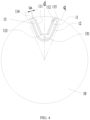
FIG. 4 is a schematic cross-sectional structure diagram of a rotor structure according to an embodiment III of the present disclosure; -
FIG. 5 is a schematic cross-sectional structure diagram of a rotor structure not forming part of the present invention; -
FIG. 6 is a schematic cross-sectional structure diagram of a rotor structure according to an embodiment V of the present disclosure; -
FIG. 7 is a schematic diagram showing a relationship between a thickness ratio of a permanent magnet and a torque of the rotor structure; and -
FIG. 8 is a schematic diagram showing an effect of a ratio of an area of an inner layer of magnetic steel slot to an area of an outer layer of magnetic steel slot of the rotor structure on a flux linkage. - The above drawings include following reference signs:
- 10, rotor body;
- 11, outer layer of magnetic steel slot; 111, first outer layer of magnetic steel slot; 112, second outer layer of magnetic steel slot; 113, air slot; 114, first bent slot; 115, second bent slot;
- 12, inner layer of magnetic steel slot; 13, magnetic conduction channel; 131, connection hole; 14, rotating shaft hole;
- 20, permanent magnet;
- 30, stator; 31, winding.
- The present disclosure will be described in detail below with reference to the accompanying drawings and in conjunction with the embodiments.
- As shown in
FIG. 2 to FIG. 8 , a rotor structure is provided. - Specifically, the rotor structure includes a
rotor body 10 on which a magnetic steel slot group is provided. The magnetic steel slot group includes an outer layer ofmagnetic steel slot 11 and an inner layer ofmagnetic steel slot 12. Amagnetic conduction channel 13 is formed between the outer layer ofmagnetic steel slot 11 and the inner layer ofmagnetic steel slot 12, and themagnetic conduction channel 13 is provided with aconnection hole 131. - According to the invention, by providing the
connection hole 131 on themagnetic conduction channel 13 formed between the outer layer ofmagnetic steel slot 11 and the inner layer ofmagnetic steel slot 12, the deformation of the rotor when the rotor rotates at a high speed is effectively reduced, and the obstruction of the connection hole of the rotor to the magnetic flux can be avoided, thereby improving the efficiency of the motor. - As shown in
FIG. 2 , a width of themagnetic conduction channel 13 adjacent to an outer edge of therotor body 10 is DT1, a width ofmagnetic conduction channel 13 adjacent to a rotatingshaft hole 14 of therotor body 10 is DT2, and a diameter of theconnection hole 131 is DK, satisfying (DT1+DK)≤DT2. Such an arrangement can effectively alleviate the magnetic saturation of a region on themagnetic conduction channel 13 where theconnection hole 131 is provided, increase a q-axis inductance of the motor, and increase a reluctance torque of the motor. - Further, 1.3×DT1≤DT2. Such an arrangement can effectively alleviate the magnetic saturation of the region on the
magnetic conduction channel 13 where theconnection hole 131 is provided, increase the q-axis inductance of the motor, and increase the reluctance torque of the motor. - According to the invention, the outer layer of
magnetic steel slot 11 includes a first outer layer ofmagnetic steel slot 111 and a second outer layer ofmagnetic steel slot 112. The first outer layer ofmagnetic steel slot 111 is located on a first side of a direct axis (d-axis) of therotor body 10. A first end of the first outer layer ofmagnetic steel slot 111 is arranged to extend toward therotating shaft hole 14 of therotor body 10 and gradually approach the direct axis of therotor body 10. A second end of the first outer layer ofmagnetic steel slot 111 is arranged to extend toward the outer edge of therotor body 10 and gradually away from the direct axis of therotor body 10. The second outer layer ofmagnetic steel slot 112 is located on a second side opposite to the first side of the direct axis of therotor body 10. A first end of the second outer layer ofmagnetic steel slot 112 is arranged to extend toward therotating shaft hole 14 of therotor body 10 and gradually approach the direct axis of therotor body 10. A second end of the second outer layer ofmagnetic steel slot 112 is arranged to extend toward the outer edge of therotor body 10 and gradually away from the direct axis of therotor body 10. Such an arrangement can better guide the magnetic field lines of a stator into each magnetic conduction channel more evenly. - The first end of the first outer layer of
magnetic steel slot 111 is in communication with the first end of the second outer layer ofmagnetic steel slot 112. Such an arrangement can better conduct the magnetic field lines. - According to the invention, the outer layer of
magnetic steel slot 11 further includes anair slot 113. A first end of theair slot 113 is in communication with the first end of the first outer layer ofmagnetic steel slot 111, and a second end of theair slot 113 is in communication with the first end of the second outer layer ofmagnetic steel slot 112. Such an arrangement can better guide the magnetic field lines, and obtain a larger q-axis inductance. - In the embodiment, the outer layer of
magnetic steel slot 11 further includes a firstbent slot 114. A first end of the firstbent slot 114 is in communication with the second end of the first outer layer ofmagnetic steel slot 111. A second end of the firstbent slot 114 is arranged to extend toward the outer edge of therotor body 10 and gradually away from the direct axis of therotor body 10. A first angle is formed between a geometric central line of the firstbent slot 114 and a geometric central line of the first outer layer ofmagnetic steel slot 111. By providing the angle between the magnetic steel slot and bent slot, it can more effectively guide the q-axis magnetic flux linkage lines of thestator 30 into each magnetic conduction channel more evenly, increase the q-axis inductance of the motor, and increase the reluctance torque of the motor. - Further, a width from the first end to the second end of the first
bent slot 114 is gradually decreased. Such an arrangement can better guide the magnetic field lines, and obtain a larger q-axis inductance. As shown inFIG. 4 , a distance between an end of a side wall of the firstbent slot 114 adjacent to the direct axis of therotor body 10 and an extension line of a side wall of the first outer layer ofmagnetic steel slot 111 away from the direct axis of therotor body 10 is Ga, satisfying Ga=N×g, and g is a length of an air gap between the stator and the rotor, and N is an integer. Such an arrangement can effectively reduce the harmonic magnetic field content of the air gap, and reduce a harmonic loss and a torque ripple of the motor. - In the embodiment, the outer layer of
magnetic steel slot 11 further includes a secondbent slot 115. A first end of the secondbent slot 115 is in communication with the second end of the second outer layer ofmagnetic steel slot 112, and a second end of the secondbent slot 115 is arranged to extend toward the outer edge of therotor body 10 and gradually away from the direct axis of therotor body 10. A second angle is formed between a geometric central line of the secondbent slot 115 and a geometric central line of the second outer layer ofmagnetic steel slot 112. Such an arrangement can better guide the magnetic field lines, and obtain a larger q-axis inductance. - According to the invention, the rotor structure further includes a plurality of
permanent magnets 20. The plurality ofpermanent magnets 20 are disposed in the first outer layer ofmagnetic steel slot 111, the second outer layer ofmagnetic steel slot 112, and the inner layer ofmagnetic steel slot 12, respectively. Such an arrangement can guide the magnetic field lines of the stator into each magnetic conduction channel more evenly. - Lengths of the
permanent magnets 20 respectively disposed in the first outer layer ofmagnetic steel slot 111 and the second outer layer ofmagnetic steel slot 112 are L. A maximum width between apermanent magnet 20 disposed in the first outer layer ofmagnetic steel slot 111 and apermanent magnet 20 disposed in the second outer layer ofmagnetic steel slot 112 is C, satisfying 0.8×C≤ L. Such an arrangement allows more permanent magnets to be disposed in the same rotor, thereby increasing the efficiency and anti-demagnetization capability of the motor. - According to the invention, for the
permanent magnet 20 provided in the first outer layermagnetic steel slot 111, a third angle α1 is formed between a connection line which is formed by connecting a side wall of thepermanent magnet 20 adjacent to the direct axis of therotor body 10 and adjacent to the edge of therotor body 10 with therotating shaft hole 14 of therotor body 10, and the direct axis of therotor body 10. For thepermanent magnet 20 provided in the inner layer ofmagnetic steel slot 12, a fourth angle α2 is formed between a connection line which is formed by connecting a side wall of the permanent magnet 20adjacent to the direct axis of therotor body 10 and adjacent to the edge of therotor body 10 with therotating shaft hole 14 of therotor body 10, and the direct axis of therotor body 10, satisfying 1.5×(sina1/sina2)≤S1/S2≤1.8×(sinα1/sinα2), where S1 is a sum of a surface area of one side of thepermanent magnet 20 disposed in the first outer layer ofmagnetic steel slot 111 adjacent to the direct axis of therotor body 10 and a surface area of one side of thepermanent magnet 20 disposed in the second outer layer ofmagnetic steel slot 112 adjacent to the direct axis of therotor body 10, and S2 is a surface area of thepermanent magnet 20 disposed in the inner layer ofmagnetic steel slot 12 adjacent to the direct axis of therotor body 10. By setting the arrangement shape of the outer-layer of permanent magnet and a ratio of a thickness of the inner layer of the permanent magnet to a thickness of the outer-layer of permanent magnet, a working point of the permanent magnet can be better adjusted, so that the average working point of the inner layer and outer layer of the permanent magnets is higher. - In the embodiment, a connection line formed by connecting a midpoint of a side wall of the
air slot 113 adjacent to the edge of therotor body 10 with the edge of therotor body 10 has a midpoint P. a distance between therotating shaft hole 14 of therotor body 10 and the point P is taken as a radius, and a circular arc is made with the radius along the circumferential direction of therotor body 10. A sum of thicknesses of thepermanent magnets 20 intersecting the circular arc is M1, and a circumference of the circular arc is C1, where M1/C1 = T2 and 55%≤T2≤65%. Such an arrangement can ensure a higher working point of the permanent magnet, obtain a larger anti-demagnetization capability and a higher no-load flux linkage of motor, and enable the motor to obtain a larger difference between the quadrature-axis inductance and the direct-axis inductance, and increase the reluctance torque of the motor. - In the embodiment, the width of the
magnetic conduction channel 13 gradually decreases outwardly in a radial direction of therotor body 10. Such an arrangement can allow more magnetic field lines of thestator 30 to enter the magnetic conduction channel, and allow the rotor to obtain a larger reluctance torque, thereby improving the working efficiency of the rotor. - The number of at least one of the outer layer of
magnetic steel slot 11 and the inner layer ofmagnetic steel slot 12 is multiple. Such an arrangement can allow the rotor to obtain a larger reluctance torque, thereby improving the working efficiency of the rotor. - In the embodiment, the inner layer of
magnetic steel slot 12 has a U-shaped structure, and an arc-shaped portion of the inner layer ofmagnetic steel slot 12 is arranged to protrude toward therotating shaft hole 14 of therotor body 10. Such an arrangement can further adjust a distribution of the magnetic field lines of each magnetic conduction channel, and reduce the local saturation. - The rotor structure in the above-mentioned embodiments can also be used in the field of motor equipment technology, that is, according to another aspect of the present disclosure, a permanent magnet auxiliary synchronous reluctance motor is provided. The motor includes a rotor structure which is the rotor structure in the above-mentioned embodiments.
- The rotor structure in the above-described embodiments can also be used in the field of vehicle equipment technology, that is, according to another aspect of the present disclosure, an electric vehicle is provided. The electric vehicle includes a rotor structure which is the rotor structure as described above.
- As shown in
FIG. 1 , in order to increase the mechanical strength of the rotor, an existing permanent magnet auxiliary synchronous reluctance motor is generally provided with a connection hole on the rotor, and a structural reinforcing rod such as a rivet or a screw is placed in the connection hole. In general, there are two arrangement modes for the connection hole of the rotor. In one arrangement mode, the connection hole of the rotor is located between the magnetic steel slot and the shaft hole, such as the connection hole at a bottom of the rotor as shown inFIG. 1 . Since the region in which the rotor is easily deformed is an region outside the magnetic steel slot when the rotor rotates at a high speed, such connection hole at the bottom of the rotor is less effective in suppressing the deformation of the rotor. In the other arrangement mode, the connection hole of the rotor is located at the outermost region of the magnetic steel slot, so that the deformation of the rotor in this region can be effectively suppressed. However, in this manner, the magnetic field lines of the permanent magnet are easily blocked from entering the stator, which may cause a problem of reduced motor efficiency. - To this end, the present disclosure proposes a motor provide with a new arrangement of connection holes of the rotor. The motor includes a stator and a rotor. The stator includes a stator core and a stator winding 31 embedded in the stator core. The rotor includes a magnetic steel slot and a permanent magnet disposed in the magnetic steel slot. The rotor includes multiple layers of permanent magnets on a same magnetic pole. In the present technical solution, multiple layers refer to that the number of layers is greater than or equal to two. The permanent magnets on the same magnetic pole has the same polarity toward the stator. The magnetic steel slot has a shape protruding toward the inner side of the rotor, both ends of the magnetic steel slot are adjacent to an outer edge of the rotor, and a center of the magnetic steel slot is adjacent to the inner side of the rotor. A magnetic conduction channel is formed between any two adjacent magnetic steel slots on the same magnetic pole. The magnetic conduction channel has a region with an increased thickness adjacent to the bottom of the rotor, in the region a connection hole of the rotor is arranged, as shown in
FIG. 2 andFIG. 3 . By arranging the connection hole of the rotor at the bottom of the magnetic conduction channel, the deformation of the rotor when the rotor rotates at a high speed is effectively reduced, and the obstruction of the connection hole of the rotor to the magnetic flux can be avoided, thereby improving the efficiency of the motor. - According to the invention, by setting the thickness DT2 of the region with the increased thickness of the
magnetic conduction channel 13 to be not less than 1.3 times the width DT1 of the magnetic conduction channel adjacent to the outer edge of the rotor, or by setting the width DT2 of the magnetic conduction channel to be not less than the sum of the width DT1 of the magnetic conduction channel and the diameter DK of the connection hole, accordingly, the magnetic saturation of a region on themagnetic conduction channel 13 where theconnection hole 131 of the rotor is placed can be effectively alleviated, the q-axis inductance of the motor is increased, and the reluctance torque of the motor is increased. - A bottom portion of the magnetic steel slot adjacent to the magnetic conduction channel in which the connection hole of the rotor is disposed and adjacent to the center of the rotor has an arc shape protruding toward the inner side of the rotor. By setting the magnetic steel slot to have the arc shape, more permanent magnets can be disposed under a condition of forming the same width DT2 of the magnetic conduction channel, thereby increasing the no-load flux linkage of the motor.
- The magnetic steel slot adjacent to the magnetic conduction channel in which the connection hole of the rotor is disposed and adjacent to an outer side of the rotor is substantially V-shaped, which can form a magnetic conduction channel of DT2 width with a larger thickness more easily.
- As shown in
FIG. 4 , an innermost layer of permanent magnet of the rotor is taken as a first layer, an end of the second layer magnetic steel slot calculated from inside to outside has a turn deflecting toward the end of the inner layer magnetic steel slot. - As shown in
FIG. 5 , the study finds that when three-phase symmetrical alternating current flows through the stator of the motor, the distribution of the magnetic field lines on each tooth of the stator is uneven. In the position closer to the boundary line, there are more magnetic field lines distributed on the teeth of the stator. - Further, the q-axis magnetic flux linkage lines enter three magnetic conduction channels from the stator teeth respectively. A magnetic conduction channel f3 is formed between two innermost layers of permanent magnet slots of two adjacent magnetic poles; a magnetic conduction channel f2 is formed between the innermost layer of permanent magnet slot and the second layer of permanent magnet slot; and a magnetic conduction channel f1 is formed by a magnetic conduction region between the second layer of permanent magnet slot and the outer edge of the rotor. Due to the uneven distribution of the magnetic field lines in the stator teeth, the most magnetic field lines enter the magnetic conduction channel f3, and the fewest magnetic field lines enter the magnetic conduction channel f1. The magnetic circuits of the magnetic conduction channel f3 and the magnetic conduction channel f2 are relatively saturated. When the motor load is heavier, the q-axis inductance of the motor is greatly decreased, thus affecting the usage of the reluctance torque of the motor, and this phenomenon becomes more serious especially for a ferrite permanent magnet auxiliary synchronous reluctance motor, because in this case, in order to improve the efficiency and anti-demagnetization capability of the motor, the permanent magnet is thicker, and it is difficult to increase the width of the magnetic conduction channel. To this end, the present solution provides that an end of the magnetic conduction channel has a turn deflecting toward an end of the inner layer of permanent magnet. The distribution of the q-axis magnetic field lines f of the motor is shown in
FIG. 7 . By providing that the end of the magnetic conduction channel has a turn deflecting toward the end of the inner layer of permanent magnet slot, directions of the q-axis magnetic field lines f of the stator can be effectively guided, and the magnetic field lines which originally enter the high magnetic saturation region, such as the magnetic field lines entering the magnetic conduction channel f2 shown in the figure, are changed to enter the low magnetic saturation region such as the magnetic conduction channel f1 shown in the figure. Accordingly, more magnetic fluxes are generated under the same exciting current, thereby improving the q-axis inductance of the motor, increasing the reluctance torque of the motor, and improving the efficiency and the power density of the motor. - In the embodiment, compared to an end point of the end edge line of the second layer of permanent magnet slot adjacent to the inner side before turning, an end point of the end edge line of the second layer of permanent magnet slot adjacent to the outer side is closer to the q-axis of the rotor. Such arrangement is for implementing a better guidance effect of the magnetic field lines.
- The shape of the end of the magnetic conduction channel before turning is determined by the following method: when a flat permanent magnet is installed in the permanent magnet slot, two side edge lines of the permanent magnet slot are extended, and a distance between an outer edge line of the permanent magnet slot adjacent to the rotor and the outer edge of the rotor is unchanged after the permanent magnet slot is bent. When an arc-shaped permanent magnet is installed in the permanent magnet slot, an arc-shaped tangent line is taken at an end point of the arc-shaped permanent magnet slot, and the tangent line is extended, and a distance between an outer edge line of the permanent magnet slot adjacent to the rotor and the outer edge of the rotor is unchanged after the permanent magnet slot is bent. Further, a distance between the end point of the end edge line of the bent slot of the second layer of permanent magnet slot adjacent to the outer side and the end point of the end edge line of the second layer of permanent magnet slot adjacent to the inner side before turning is Ga, and the distance Ga is substantially equal to an integral multiple of a length g of an air gap between the stator and the rotor. By setting the distance Ga to be substantially the integral multiple of the length g of the air gap between the stator and the rotor, the harmonic magnetic field content in the air gap can be effectively reduced, thereby reducing the harmonic loss and the torque ripple of the motor. The substantial equation herein ranges from 0.95 times to 1.05 times. In addition, there is no permanent magnet placed in the bent portion at the end of the permanent magnet slot, which can effectively alleviate the local demagnetization of the end of the permanent magnet and improve the anti-demagnetization ability of the motor.
- As shown in
FIG. 6 andFIG. 7 , the permanent magnet of the rotor of the motor is a ferrite permanent magnet. An arc centered on a center of the rotor is made, and the arc passes through a midpoint P of an outer edge line of the outermost layer of permanent magnet. A ratio of a total sum of thicknesses of the permanent magnets of the rotor at the arc to a circumference of the arc is 45% to 70%. When the permanent magnet of the rotor of the motor is the ferrite permanent magnet, by setting the thickness of the permanent magnet to be in the above-mentioned range, a ratio of the thickness of the permanent magnet to the thickness of the magnetic conduction channel is made in a better range, which can ensure a higher working point of the permanent magnet, thereby achieving a larger anti-demagnetization capability and a higher no-load flux linkage of the motor; moreover, the motor can achieve a larger difference between the quadrature-axis inductance and the direct-axis inductance, thereby improving the reluctance torque of the motor. - Further, in order to enhance the mechanical strength of the rotor, one or more magnetic isolation bridges are formed between layers of permanent magnet slots.
- Further, two ends of the inner layer of permanent magnet slot of the rotor adjacent to the outer edge of the rotor are respectively provided with a flat permanent magnet, and an end of the second layer of permanent magnet slot adjacent to the outer edge of the rotor is provided with a flat permanent magnet. By providing the flat permanent magnet at the end of the permanent magnet slot, more permanent magnets can be placed in the same rotor, thereby improving the efficiency and the anti-demagnetization capability of the motor.
- As shown in
FIG. 6 , there are two layers of permanent magnets of the rotor. The outer layer of permanent magnet slot is substantially V-shaped. A length of the permanent magnet on one side of the V-shaped permanent magnet slot is L, a maximum width of the V-shaped permanent magnet is C, satisfying 0.8×C≤L. The inner layer of permanent magnet slot is substantially U-shaped and consists of at least three sections of permanent magnets. A ratio of a surface area of the outer layer of permanent magnet adjacent to the outer side of the rotor to a surface area of the inner layer of permanent magnet adjacent to the outer side of rotor is S1/S2. An angle formed by an outer vertex of the end of the outer layer of permanent magnet adjacent to the outside surface of the rotor and the center of the rotor is 2×α1, and an angle formed by an outer vertex of the end of the inner layer of permanent magnet adjacent to the outside surface of the rotor and the center of the rotor is 2×α2, and the following relationship is satisfied: 1.3×(sinα1/sinα2)≤S1/S2≤2×(sinα1/sinα2). - As shown in
FIG. 8 , by setting the arrangement shape of the outer layer of permanent magnet and the ratio of the area of the inner layer of permanent magnet to the area of the outer layer of permanent magnet, the working point of the permanent magnet can be better adjusted, so that an average working point of the inner layer and outer layer of permanent magnet becomes higher, and a proportion of the magnetic field lines of the inner layer of permanent magnet entering the outer layer of permanent magnet and that directly entering thestator 30 are more reasonable. Accordingly, the permanent magnet flux linkage of the motor is increased, thereby improving the efficiency and the power factor of the motor. The effect of the ratio of the surface area of the inner layer of permanent magnet to the surface area of the outer layer of permanent magnet on the magnetic flux linkage of the motor are shown in the figure. By setting the ratio of the surface area of the inner layer of permanent magnet to the surface area of the outer layer of permanent magnet to satisfy: 1.3×(sinα1/sinα2)≤S1/S2≤2×(sinα1/sinα2), a larger no-load flux linkage of the motor can be achieved. Preferably, 1.5×(sinα1/sinα2) ≤S1/S2 ≤1.8×(sinα1/sinα2). - Further, the width of the magnetic conduction channel formed by the inner layer of rectangular permanent magnet and the outer layer of rectangular permanent magnet is not constant. The width of a portion of the magnetic conduction channel adjacent to the outer surface of the rotor is smaller. By designing the width of the magnetic conduction channel to be gradually reduced, all magnetic poles of the rotor are evenly distributed on the circumference of rotor. The magnetic flux areas of the inner layer and outer layer of permanent magnets can be better adjusted, to achieve a consistent adjustment of the working points of the inner layer and outer layer of permanent magnets.
- In addition, the motor in the embodiments can serve as a drive motor of an electric vehicle, accordingly, the cost of the motor can be reduced, and the dependence of the new energy electric vehicle on the rare earth resources can be effectively reduced. Meanwhile, the motor of the present disclosure has the advantages of the high efficiency of the rare earth permanent magnet motor and the high reliability of the asynchronous motor, and can better promote the development of the new energy vehicle.
- What described above are preferred embodiments of the present disclosure, but not intended to limit the present disclosure. For those skilled in the art, various amendments and modifications can be made within the scope of the appended claims.
Claims (13)
- A rotor structure, characterized by comprising:a rotor body (10) provided with a magnetic steel slot group symmetrically arranged around each direct axis of the rotor body; wherein the magnetic steel slot group comprises an outer layer of magnetic steel slot (11) and an inner layer of magnetic steel slot (12), a magnetic conduction channel (13) is formed between the outer layer of magnetic steel slot (11) andthe inner layer of magnetic steel slot (12), the magnetic conduction channel (13) is provided with a connection hole (131) for placement of a structural reinforcement rod therein; wherein, a width of the magnetic conduction channel (13) adjacent to an outer edge of the rotor body (10) is DT1, a width of the magnetic conduction channel (13) adjacent to a rotating shaft hole (14) of the rotor body (10) is DT2, a diameter of the connection hole (131) is DK, satisfying (DT1+DK)≤DT2;wherein, the outer layer of magnetic steel slot (11) comprises:a first outer layer of magnetic steel slot (111) located on a first side of a direct axis of the rotor body (10), a first end of the first outer layer of magnetic steel slot (111) arranged to extend toward the rotating shaft hole (14) of the rotor body (10) and gradually approach the direct axis of the rotor body (10), a second end of the first outer layer of magnetic steel slot (111) arranged to extend toward the outer edge of the rotor body (10) and gradually away from the direct axis of the rotor body (10); anda second outer layer of magnetic steel slot (112) located on a second side opposite to the first side of the direct axis of the rotor body (10), a first end of the second outer layer of magnetic steel slot (112) arranged to extend toward the rotating shaft hole (14) of the rotor body (10) and gradually approach the direct axis of the rotor body (10), a second end of the second outer layer of magnetic steel slot (112) arranged to extend toward the outer edge of the rotor body (10) and gradually away from the direct axis of the rotor body (10);wherein the rotor structure further comprises:a plurality of permanent magnets (20); wherein the plurality of permanent magnets are respectively disposed in the first outer layer of magnetic steel slot (111), the second outer layer of magnetic steel slot (112), and the inner layer of magnetic steel slot (12);characterized in that: the outer layer of magnetic steel slot (11) further comprises: an air slot (113), wherein a first end of the air slot (113) is in communication with the first end of the first outer layer of magnetic steel slot (111), and a second end of the air slot (113) is in communication with the first end of the second outer layer of magnetic steel slot (112);wherein, a permanent magnet (20) is disposed in the first outer layer of magnetic steel slot (111), a third angle α1 is formed between a connection line which is formed by connecting a side wall of the permanent magnet (20) adjacent to the direct axis of the rotor body (10) and adjacent to an edge of the rotor body (10) with the rotating shaft hole (14) of the rotor body (10), and the direct axis of the rotor body (10) an inner layer of permanent magnet is disposed in the inner layer of magnetic steel slot (12), a fourth angle α2 is formed between a connection line which is formed by connecting a side wall of the inner layer of permanent magnet adjacent to the direct axis of the rotor body (10) and adjacent to the edge of the rotor body (10) with the rotating shaft hole (14) of the rotor body (10), and the direct axis of the rotor body (10), satisfying 1.5×(sina1/sina2)≤S1/S2≤1.8×(sinα1/sinα2), S1 is a sum of a surface area of the side of the permanent magnet (20) disposed in the first outer layer of magnetic steel slot (111) adjacent to the direct axis of the rotor body (10) and a surface area of the side of the permanent magnet (20) disposed in the second outer layer of magnetic steel slot (112) adjacent to the direct axis of the rotor body (10), and S2 is a surface area of the side of the inner layer of permanent magnet disposed in the inner layer of magnetic steel slot (12) adjacent to the direct axis of the rotor body (10).
- The rotor structure according to claim 1, satisfying 1.3×DT1≤DT2.
- The rotor structure according to claim 2,wherein, the first end of the first outer layer of magnetic steel slot (111) is in communication with the first end of the second outer layer of magnetic steel slot (112).
- The rotor structure according to claim 1, wherein, the outer layer of magnetic steel slot (11) further comprises:a first bent slot (114), wherein a first end of the first bent slot (114) is in communication with the second end of the first outer layer of magnetic steel slot (111), a second end of the first bent slot (114) is arranged to extend toward the outer edge of the rotor body (10) and gradually away from the direct axis of the rotor body (10), a first angle is formed between a geometric central line of the first bent slot (114) and a geometric central line of the first outer layer of magnetic steel slot (111);wherein, a width of the first bent slot (114) is gradually decreased from the first end to the second end of the first bent slot (114).
- The rotor structure according to claim 4, wherein, a distance from an end of a side wall of the first bent slot (114) adjacent to the direct axis of the rotor body (10) to an extension line of a side wall of the first outer layer of magnetic steel slot (111) away from the direct axis of the rotor body (10) is Ga, wherein Ga=N×g, g is a length of an air gap between a stator and a rotor, and N is an integer.
- The rotor structure according to claim 4, wherein, the outer layer of magnetic steel slot (11) further comprises:
a second bent slot (115), wherein a first end of the second bent slot (115) is in communication with the second end of the second outer layer of magnetic steel slot (112), and a second end of the second bent slot (115) is arranged to extend toward the outer edge of the rotor body (10) and gradually away from the direct axis of the rotor body (10), a second angle is formed between a geometric central line of the second bent slot (115) and a geometric central line of the second outer layer of magnetic steel slot (111). - The rotor structure according to claim 1, wherein, lengths of the permanent magnets (20) respectively disposed in the first outer layer of magnetic steel slot (111) and the second outer layer of magnetic steel slot (112) in a radial direction of the rotor body (10) are L, and a maximum width between the permanent magnet (20) disposed in the first outer layer of magnetic steel slot (111) and the permanent magnet (20) disposed in the second outer layer of magnetic steel slot (112) adjacent to an outer edge of the rotor body (10) is C, satisfying 0.8×C≤L.
- The rotor structure according to claim 7, wherein, a midpoint of a connection line formed by connecting a midpoint of a side wall of the air slot (113) adjacent to an edge of the rotor body (10) with the edge of the rotor body (10) is a point P, a distance between the rotating shaft hole (14) of the rotor body (10) and the point P is taken as a radius, a circular arc is made with the radius along a circumferential direction of the rotor body (10), a sum of thicknesses of the permanent magnets (20) intersecting the circular arc is M1, and a circumference of the circular arc is C1, satisfying M1/C1 = T2, and 55%≤T2≤65%.
- The rotor structure according to claim 1, wherein, a width of the magnetic conduction channel (13) is gradually decreased outwardly in a radial direction of the rotor body (10).
- The rotor structure according to claim 1, wherein, a number of at least one of the outer layer of magnetic steel slot (11) and the inner layer of magnetic steel slot (12) is multiple.
- The rotor structure according to claim 1, wherein, the inner layer of magnetic steel slot (12) has a U-shaped structure, an arc-shaped portion of the inner layer of magnetic steel slot (12) is arranged to protrude toward the rotating shaft hole (14) of the rotor body (10).
- A permanent magnet auxiliary synchronous reluctance motor, characterized by comprising a rotor structure, wherein the rotor structure is the same as that of any one of claims 1 to 11.
- An electric vehicle, characterized by comprising a rotor structure, wherein the rotor structure is the same as that of any one of claims 1 to 11.
Applications Claiming Priority (2)
| Application Number | Priority Date | Filing Date | Title |
|---|---|---|---|
| CN201810218934.0A CN108321951B (en) | 2018-03-16 | 2018-03-16 | Rotor structure, permanent magnet auxiliary synchronous reluctance motor and electric automobile |
| PCT/CN2018/119874 WO2019174325A1 (en) | 2018-03-16 | 2018-12-07 | Rotor structure, permanent magnet auxiliary synchronous reluctance motor and electric vehicle |
Publications (3)
| Publication Number | Publication Date |
|---|---|
| EP3767797A1 EP3767797A1 (en) | 2021-01-20 |
| EP3767797A4 EP3767797A4 (en) | 2021-04-28 |
| EP3767797B1 true EP3767797B1 (en) | 2023-06-07 |
Family
ID=62897897
Family Applications (1)
| Application Number | Title | Priority Date | Filing Date |
|---|---|---|---|
| EP18910127.2A Active EP3767797B1 (en) | 2018-03-16 | 2018-12-07 | Rotor structure, permanent magnet auxiliary synchronous reluctance motor and electric vehicle |
Country Status (4)
| Country | Link |
|---|---|
| US (1) | US11699930B2 (en) |
| EP (1) | EP3767797B1 (en) |
| CN (1) | CN108321951B (en) |
| WO (1) | WO2019174325A1 (en) |
Families Citing this family (6)
| Publication number | Priority date | Publication date | Assignee | Title |
|---|---|---|---|---|
| CN108321951B (en) | 2018-03-16 | 2019-12-27 | 珠海格力电器股份有限公司 | Rotor structure, permanent magnet auxiliary synchronous reluctance motor and electric automobile |
| CN108566006A (en) * | 2018-03-16 | 2018-09-21 | 珠海格力节能环保制冷技术研究中心有限公司 | Rotor structure, permanent magnetism assist in synchronization reluctance motor and electric vehicle |
| CN108336845B (en) | 2018-03-16 | 2020-11-03 | 珠海格力节能环保制冷技术研究中心有限公司 | Rotor structure, permanent magnet auxiliary synchronous reluctance motor and electric automobile |
| CN110011444B (en) * | 2019-04-26 | 2025-03-04 | 珠海格力节能环保制冷技术研究中心有限公司 | Motor rotor, motor and compressor |
| CN114204710B (en) * | 2021-12-31 | 2023-09-26 | 江苏大学 | Variable salient pole rate permanent magnet motor and design method thereof |
| JPWO2023238309A1 (en) * | 2022-06-09 | 2023-12-14 |
Family Cites Families (13)
| Publication number | Priority date | Publication date | Assignee | Title |
|---|---|---|---|---|
| US8760025B2 (en) | 2012-08-09 | 2014-06-24 | GM Global Technologies Operations LLC | Interior permanent magnet machine having off axis centered arc geometry |
| PL2744076T3 (en) * | 2012-12-14 | 2017-07-31 | Abb Schweiz Ag | Rotor for an electric machine, an electric machine and a method for manufacturing an electric machine |
| JP2015122936A (en) | 2013-10-31 | 2015-07-02 | 三星電子株式会社Samsung Electronics Co.,Ltd. | Magnet embedded-type motor and method for using magnet embedded-type motor |
| KR20150078467A (en) | 2013-12-30 | 2015-07-08 | 현대자동차주식회사 | Rotor for interior permanent magnet motor |
| FR3019948B1 (en) | 2014-04-10 | 2017-12-22 | Moteurs Leroy-Somer | ROTOR OF ELECTRIC ROTATING MACHINE. |
| US9925889B2 (en) * | 2015-08-24 | 2018-03-27 | GM Global Technology Operations LLC | Electric machine for hybrid powertrain with dual voltage power system |
| CN106936284B (en) * | 2015-12-29 | 2024-04-16 | 丹佛斯(天津)有限公司 | Electric Motor |
| EP3261220B1 (en) * | 2016-06-23 | 2020-08-12 | Volvo Car Corporation | Electric machine |
| DE102016212022A1 (en) * | 2016-07-01 | 2018-01-04 | Volkswagen Aktiengesellschaft | rotor |
| DE102016225890B3 (en) | 2016-12-21 | 2018-05-30 | Magna powertrain gmbh & co kg | Rotor for an electric machine |
| CN107222047B (en) * | 2017-08-09 | 2023-07-21 | 珠海格力节能环保制冷技术研究中心有限公司 | Tangential motor, tangential motor rotor and rotor core |
| CN208015468U (en) * | 2018-03-16 | 2018-10-26 | 珠海格力节能环保制冷技术研究中心有限公司 | Rotor structure, permanent magnetism assist in synchronization reluctance motor and electric vehicle |
| CN108321951B (en) | 2018-03-16 | 2019-12-27 | 珠海格力电器股份有限公司 | Rotor structure, permanent magnet auxiliary synchronous reluctance motor and electric automobile |
-
2018
- 2018-03-16 CN CN201810218934.0A patent/CN108321951B/en active Active
- 2018-12-07 EP EP18910127.2A patent/EP3767797B1/en active Active
- 2018-12-07 US US16/979,827 patent/US11699930B2/en active Active
- 2018-12-07 WO PCT/CN2018/119874 patent/WO2019174325A1/en not_active Ceased
Also Published As
| Publication number | Publication date |
|---|---|
| CN108321951B (en) | 2019-12-27 |
| EP3767797A4 (en) | 2021-04-28 |
| CN108321951A (en) | 2018-07-24 |
| US11699930B2 (en) | 2023-07-11 |
| EP3767797A1 (en) | 2021-01-20 |
| US20210057946A1 (en) | 2021-02-25 |
| WO2019174325A1 (en) | 2019-09-19 |
Similar Documents
| Publication | Publication Date | Title |
|---|---|---|
| EP3767797B1 (en) | Rotor structure, permanent magnet auxiliary synchronous reluctance motor and electric vehicle | |
| EP3767795B1 (en) | Rotor structure, permanent magnet auxiliary synchronous reluctance motor, and electric vehicle | |
| US11637464B2 (en) | Rotor structure, permanent magnet auxiliary synchronous reluctance motor and electric vehicle | |
| CN104638863B (en) | A kind of permagnetic synchronous motor | |
| US6268677B1 (en) | Rotor for permanent magnet type rotating machine | |
| US11799333B2 (en) | Permanent magnet auxiliary synchronous reluctance motor and electric vehicle provided with same | |
| US11011965B2 (en) | Permanent magnet synchronous motor | |
| EP3089327B1 (en) | Permanent magnet motor | |
| EP3767796B1 (en) | Rotor structure, permanent magnet auxiliary synchronous reluctance motor and electric vehicle | |
| CN120185248A (en) | Rotor assembly and self-starting permanent magnet synchronous reluctance motor | |
| CN111082560B (en) | Motor rotor and motor | |
| CN110620447B (en) | Permanent magnet motor and compressor | |
| CN208015468U (en) | Rotor structure, permanent magnetism assist in synchronization reluctance motor and electric vehicle |
Legal Events
| Date | Code | Title | Description |
|---|---|---|---|
| STAA | Information on the status of an ep patent application or granted ep patent |
Free format text: STATUS: THE INTERNATIONAL PUBLICATION HAS BEEN MADE |
|
| PUAI | Public reference made under article 153(3) epc to a published international application that has entered the european phase |
Free format text: ORIGINAL CODE: 0009012 |
|
| STAA | Information on the status of an ep patent application or granted ep patent |
Free format text: STATUS: REQUEST FOR EXAMINATION WAS MADE |
|
| 17P | Request for examination filed |
Effective date: 20200901 |
|
| AK | Designated contracting states |
Kind code of ref document: A1 Designated state(s): AL AT BE BG CH CY CZ DE DK EE ES FI FR GB GR HR HU IE IS IT LI LT LU LV MC MK MT NL NO PL PT RO RS SE SI SK SM TR |
|
| AX | Request for extension of the european patent |
Extension state: BA ME |
|
| A4 | Supplementary search report drawn up and despatched |
Effective date: 20210331 |
|
| RIC1 | Information provided on ipc code assigned before grant |
Ipc: H02K 1/27 20060101AFI20210325BHEP Ipc: H02K 29/03 20060101ALI20210325BHEP Ipc: H02K 1/24 20060101ALN20210325BHEP |
|
| DAV | Request for validation of the european patent (deleted) | ||
| DAX | Request for extension of the european patent (deleted) | ||
| REG | Reference to a national code |
Ref country code: DE Ref legal event code: R079 Ref document number: 602018051674 Country of ref document: DE Free format text: PREVIOUS MAIN CLASS: H02K0001270000 Ipc: H02K0029030000 |
|
| RIC1 | Information provided on ipc code assigned before grant |
Ipc: H02K 1/24 20060101ALN20221125BHEP Ipc: H02K 1/276 20220101ALI20221125BHEP Ipc: H02K 29/03 20060101AFI20221125BHEP |
|
| GRAP | Despatch of communication of intention to grant a patent |
Free format text: ORIGINAL CODE: EPIDOSNIGR1 |
|
| STAA | Information on the status of an ep patent application or granted ep patent |
Free format text: STATUS: GRANT OF PATENT IS INTENDED |
|
| RIC1 | Information provided on ipc code assigned before grant |
Ipc: H02K 1/24 20060101ALN20221212BHEP Ipc: H02K 1/276 20220101ALI20221212BHEP Ipc: H02K 29/03 20060101AFI20221212BHEP |
|
| INTG | Intention to grant announced |
Effective date: 20230109 |
|
| GRAS | Grant fee paid |
Free format text: ORIGINAL CODE: EPIDOSNIGR3 |
|
| GRAA | (expected) grant |
Free format text: ORIGINAL CODE: 0009210 |
|
| STAA | Information on the status of an ep patent application or granted ep patent |
Free format text: STATUS: THE PATENT HAS BEEN GRANTED |
|
| AK | Designated contracting states |
Kind code of ref document: B1 Designated state(s): AL AT BE BG CH CY CZ DE DK EE ES FI FR GB GR HR HU IE IS IT LI LT LU LV MC MK MT NL NO PL PT RO RS SE SI SK SM TR |
|
| REG | Reference to a national code |
Ref country code: GB Ref legal event code: FG4D |
|
| REG | Reference to a national code |
Ref country code: CH Ref legal event code: EP Ref country code: AT Ref legal event code: REF Ref document number: 1577834 Country of ref document: AT Kind code of ref document: T Effective date: 20230615 |
|
| REG | Reference to a national code |
Ref country code: DE Ref legal event code: R096 Ref document number: 602018051674 Country of ref document: DE |
|
| P01 | Opt-out of the competence of the unified patent court (upc) registered |
Effective date: 20230530 |
|
| REG | Reference to a national code |
Ref country code: LT Ref legal event code: MG9D |
|
| REG | Reference to a national code |
Ref country code: NL Ref legal event code: MP Effective date: 20230607 |
|
| PG25 | Lapsed in a contracting state [announced via postgrant information from national office to epo] |
Ref country code: SE Free format text: LAPSE BECAUSE OF FAILURE TO SUBMIT A TRANSLATION OF THE DESCRIPTION OR TO PAY THE FEE WITHIN THE PRESCRIBED TIME-LIMIT Effective date: 20230607 Ref country code: NO Free format text: LAPSE BECAUSE OF FAILURE TO SUBMIT A TRANSLATION OF THE DESCRIPTION OR TO PAY THE FEE WITHIN THE PRESCRIBED TIME-LIMIT Effective date: 20230907 Ref country code: ES Free format text: LAPSE BECAUSE OF FAILURE TO SUBMIT A TRANSLATION OF THE DESCRIPTION OR TO PAY THE FEE WITHIN THE PRESCRIBED TIME-LIMIT Effective date: 20230607 |
|
| REG | Reference to a national code |
Ref country code: AT Ref legal event code: MK05 Ref document number: 1577834 Country of ref document: AT Kind code of ref document: T Effective date: 20230607 |
|
| PG25 | Lapsed in a contracting state [announced via postgrant information from national office to epo] |
Ref country code: RS Free format text: LAPSE BECAUSE OF FAILURE TO SUBMIT A TRANSLATION OF THE DESCRIPTION OR TO PAY THE FEE WITHIN THE PRESCRIBED TIME-LIMIT Effective date: 20230607 Ref country code: NL Free format text: LAPSE BECAUSE OF FAILURE TO SUBMIT A TRANSLATION OF THE DESCRIPTION OR TO PAY THE FEE WITHIN THE PRESCRIBED TIME-LIMIT Effective date: 20230607 Ref country code: LV Free format text: LAPSE BECAUSE OF FAILURE TO SUBMIT A TRANSLATION OF THE DESCRIPTION OR TO PAY THE FEE WITHIN THE PRESCRIBED TIME-LIMIT Effective date: 20230607 Ref country code: LT Free format text: LAPSE BECAUSE OF FAILURE TO SUBMIT A TRANSLATION OF THE DESCRIPTION OR TO PAY THE FEE WITHIN THE PRESCRIBED TIME-LIMIT Effective date: 20230607 Ref country code: HR Free format text: LAPSE BECAUSE OF FAILURE TO SUBMIT A TRANSLATION OF THE DESCRIPTION OR TO PAY THE FEE WITHIN THE PRESCRIBED TIME-LIMIT Effective date: 20230607 Ref country code: GR Free format text: LAPSE BECAUSE OF FAILURE TO SUBMIT A TRANSLATION OF THE DESCRIPTION OR TO PAY THE FEE WITHIN THE PRESCRIBED TIME-LIMIT Effective date: 20230908 |
|
| PG25 | Lapsed in a contracting state [announced via postgrant information from national office to epo] |
Ref country code: FI Free format text: LAPSE BECAUSE OF FAILURE TO SUBMIT A TRANSLATION OF THE DESCRIPTION OR TO PAY THE FEE WITHIN THE PRESCRIBED TIME-LIMIT Effective date: 20230607 |
|
| PG25 | Lapsed in a contracting state [announced via postgrant information from national office to epo] |
Ref country code: SK Free format text: LAPSE BECAUSE OF FAILURE TO SUBMIT A TRANSLATION OF THE DESCRIPTION OR TO PAY THE FEE WITHIN THE PRESCRIBED TIME-LIMIT Effective date: 20230607 |
|
| PG25 | Lapsed in a contracting state [announced via postgrant information from national office to epo] |
Ref country code: IS Free format text: LAPSE BECAUSE OF FAILURE TO SUBMIT A TRANSLATION OF THE DESCRIPTION OR TO PAY THE FEE WITHIN THE PRESCRIBED TIME-LIMIT Effective date: 20231007 |
|
| PG25 | Lapsed in a contracting state [announced via postgrant information from national office to epo] |
Ref country code: SM Free format text: LAPSE BECAUSE OF FAILURE TO SUBMIT A TRANSLATION OF THE DESCRIPTION OR TO PAY THE FEE WITHIN THE PRESCRIBED TIME-LIMIT Effective date: 20230607 Ref country code: SK Free format text: LAPSE BECAUSE OF FAILURE TO SUBMIT A TRANSLATION OF THE DESCRIPTION OR TO PAY THE FEE WITHIN THE PRESCRIBED TIME-LIMIT Effective date: 20230607 Ref country code: RO Free format text: LAPSE BECAUSE OF FAILURE TO SUBMIT A TRANSLATION OF THE DESCRIPTION OR TO PAY THE FEE WITHIN THE PRESCRIBED TIME-LIMIT Effective date: 20230607 Ref country code: PT Free format text: LAPSE BECAUSE OF FAILURE TO SUBMIT A TRANSLATION OF THE DESCRIPTION OR TO PAY THE FEE WITHIN THE PRESCRIBED TIME-LIMIT Effective date: 20231009 Ref country code: IS Free format text: LAPSE BECAUSE OF FAILURE TO SUBMIT A TRANSLATION OF THE DESCRIPTION OR TO PAY THE FEE WITHIN THE PRESCRIBED TIME-LIMIT Effective date: 20231007 Ref country code: EE Free format text: LAPSE BECAUSE OF FAILURE TO SUBMIT A TRANSLATION OF THE DESCRIPTION OR TO PAY THE FEE WITHIN THE PRESCRIBED TIME-LIMIT Effective date: 20230607 Ref country code: CZ Free format text: LAPSE BECAUSE OF FAILURE TO SUBMIT A TRANSLATION OF THE DESCRIPTION OR TO PAY THE FEE WITHIN THE PRESCRIBED TIME-LIMIT Effective date: 20230607 Ref country code: AT Free format text: LAPSE BECAUSE OF FAILURE TO SUBMIT A TRANSLATION OF THE DESCRIPTION OR TO PAY THE FEE WITHIN THE PRESCRIBED TIME-LIMIT Effective date: 20230607 |
|
| PG25 | Lapsed in a contracting state [announced via postgrant information from national office to epo] |
Ref country code: PL Free format text: LAPSE BECAUSE OF FAILURE TO SUBMIT A TRANSLATION OF THE DESCRIPTION OR TO PAY THE FEE WITHIN THE PRESCRIBED TIME-LIMIT Effective date: 20230607 |
|
| REG | Reference to a national code |
Ref country code: DE Ref legal event code: R097 Ref document number: 602018051674 Country of ref document: DE |
|
| PLBE | No opposition filed within time limit |
Free format text: ORIGINAL CODE: 0009261 |
|
| STAA | Information on the status of an ep patent application or granted ep patent |
Free format text: STATUS: NO OPPOSITION FILED WITHIN TIME LIMIT |
|
| PG25 | Lapsed in a contracting state [announced via postgrant information from national office to epo] |
Ref country code: DK Free format text: LAPSE BECAUSE OF FAILURE TO SUBMIT A TRANSLATION OF THE DESCRIPTION OR TO PAY THE FEE WITHIN THE PRESCRIBED TIME-LIMIT Effective date: 20230607 |
|
| PG25 | Lapsed in a contracting state [announced via postgrant information from national office to epo] |
Ref country code: SI Free format text: LAPSE BECAUSE OF FAILURE TO SUBMIT A TRANSLATION OF THE DESCRIPTION OR TO PAY THE FEE WITHIN THE PRESCRIBED TIME-LIMIT Effective date: 20230607 |
|
| 26N | No opposition filed |
Effective date: 20240308 |
|
| PG25 | Lapsed in a contracting state [announced via postgrant information from national office to epo] |
Ref country code: SI Free format text: LAPSE BECAUSE OF FAILURE TO SUBMIT A TRANSLATION OF THE DESCRIPTION OR TO PAY THE FEE WITHIN THE PRESCRIBED TIME-LIMIT Effective date: 20230607 Ref country code: IT Free format text: LAPSE BECAUSE OF FAILURE TO SUBMIT A TRANSLATION OF THE DESCRIPTION OR TO PAY THE FEE WITHIN THE PRESCRIBED TIME-LIMIT Effective date: 20230607 |
|
| REG | Reference to a national code |
Ref country code: CH Ref legal event code: PL |
|
| PG25 | Lapsed in a contracting state [announced via postgrant information from national office to epo] |
Ref country code: LU Free format text: LAPSE BECAUSE OF NON-PAYMENT OF DUE FEES Effective date: 20231207 |
|
| PG25 | Lapsed in a contracting state [announced via postgrant information from national office to epo] |
Ref country code: MC Free format text: LAPSE BECAUSE OF FAILURE TO SUBMIT A TRANSLATION OF THE DESCRIPTION OR TO PAY THE FEE WITHIN THE PRESCRIBED TIME-LIMIT Effective date: 20230607 |
|
| REG | Reference to a national code |
Ref country code: BE Ref legal event code: MM Effective date: 20231231 |
|
| PG25 | Lapsed in a contracting state [announced via postgrant information from national office to epo] |
Ref country code: MC Free format text: LAPSE BECAUSE OF FAILURE TO SUBMIT A TRANSLATION OF THE DESCRIPTION OR TO PAY THE FEE WITHIN THE PRESCRIBED TIME-LIMIT Effective date: 20230607 Ref country code: LU Free format text: LAPSE BECAUSE OF NON-PAYMENT OF DUE FEES Effective date: 20231207 |
|
| REG | Reference to a national code |
Ref country code: IE Ref legal event code: MM4A |
|
| PG25 | Lapsed in a contracting state [announced via postgrant information from national office to epo] |
Ref country code: IE Free format text: LAPSE BECAUSE OF NON-PAYMENT OF DUE FEES Effective date: 20231207 |
|
| PG25 | Lapsed in a contracting state [announced via postgrant information from national office to epo] |
Ref country code: BE Free format text: LAPSE BECAUSE OF NON-PAYMENT OF DUE FEES Effective date: 20231231 |
|
| PG25 | Lapsed in a contracting state [announced via postgrant information from national office to epo] |
Ref country code: CH Free format text: LAPSE BECAUSE OF NON-PAYMENT OF DUE FEES Effective date: 20231231 |
|
| PG25 | Lapsed in a contracting state [announced via postgrant information from national office to epo] |
Ref country code: IE Free format text: LAPSE BECAUSE OF NON-PAYMENT OF DUE FEES Effective date: 20231207 Ref country code: CH Free format text: LAPSE BECAUSE OF NON-PAYMENT OF DUE FEES Effective date: 20231231 Ref country code: BE Free format text: LAPSE BECAUSE OF NON-PAYMENT OF DUE FEES Effective date: 20231231 |
|
| PG25 | Lapsed in a contracting state [announced via postgrant information from national office to epo] |
Ref country code: BG Free format text: LAPSE BECAUSE OF FAILURE TO SUBMIT A TRANSLATION OF THE DESCRIPTION OR TO PAY THE FEE WITHIN THE PRESCRIBED TIME-LIMIT Effective date: 20230607 |
|
| PG25 | Lapsed in a contracting state [announced via postgrant information from national office to epo] |
Ref country code: BG Free format text: LAPSE BECAUSE OF FAILURE TO SUBMIT A TRANSLATION OF THE DESCRIPTION OR TO PAY THE FEE WITHIN THE PRESCRIBED TIME-LIMIT Effective date: 20230607 |
|
| PG25 | Lapsed in a contracting state [announced via postgrant information from national office to epo] |
Ref country code: CY Free format text: LAPSE BECAUSE OF FAILURE TO SUBMIT A TRANSLATION OF THE DESCRIPTION OR TO PAY THE FEE WITHIN THE PRESCRIBED TIME-LIMIT; INVALID AB INITIO Effective date: 20181207 |
|
| PG25 | Lapsed in a contracting state [announced via postgrant information from national office to epo] |
Ref country code: HU Free format text: LAPSE BECAUSE OF FAILURE TO SUBMIT A TRANSLATION OF THE DESCRIPTION OR TO PAY THE FEE WITHIN THE PRESCRIBED TIME-LIMIT; INVALID AB INITIO Effective date: 20181207 |
|
| PG25 | Lapsed in a contracting state [announced via postgrant information from national office to epo] |
Ref country code: TR Free format text: LAPSE BECAUSE OF FAILURE TO SUBMIT A TRANSLATION OF THE DESCRIPTION OR TO PAY THE FEE WITHIN THE PRESCRIBED TIME-LIMIT Effective date: 20230607 |
|
| PGFP | Annual fee paid to national office [announced via postgrant information from national office to epo] |
Ref country code: GB Payment date: 20251111 Year of fee payment: 8 |
|
| PGFP | Annual fee paid to national office [announced via postgrant information from national office to epo] |
Ref country code: FR Payment date: 20251110 Year of fee payment: 8 |
|
| PGFP | Annual fee paid to national office [announced via postgrant information from national office to epo] |
Ref country code: DE Payment date: 20251222 Year of fee payment: 8 |