EP3767773A1 - Power supply/demand system, control apparatus and power supply/demand method - Google Patents
Power supply/demand system, control apparatus and power supply/demand method Download PDFInfo
- Publication number
- EP3767773A1 EP3767773A1 EP19768098.6A EP19768098A EP3767773A1 EP 3767773 A1 EP3767773 A1 EP 3767773A1 EP 19768098 A EP19768098 A EP 19768098A EP 3767773 A1 EP3767773 A1 EP 3767773A1
- Authority
- EP
- European Patent Office
- Prior art keywords
- power
- converter
- instrument
- power supply
- synthesis
- Prior art date
- Legal status (The legal status is an assumption and is not a legal conclusion. Google has not performed a legal analysis and makes no representation as to the accuracy of the status listed.)
- Granted
Links
Images


Classifications
-
- H—ELECTRICITY
- H02—GENERATION; CONVERSION OR DISTRIBUTION OF ELECTRIC POWER
- H02J—ELECTRIC POWER NETWORKS; CIRCUIT ARRANGEMENTS OR SYSTEMS FOR SUPPLYING OR DISTRIBUTING ELECTRIC POWER; SYSTEMS FOR STORING ELECTRIC ENERGY
- H02J3/00—Circuit arrangements for AC mains or AC distribution networks
- H02J3/38—Arrangements for feeding a single network from two or more generators or sources in parallel; Arrangements for feeding already energised networks from additional generators or sources in parallel
- H02J3/46—Controlling the sharing of generated power between the generators, sources or networks
-
- B—PERFORMING OPERATIONS; TRANSPORTING
- B60—VEHICLES IN GENERAL
- B60L—PROPULSION OF ELECTRICALLY-PROPELLED VEHICLES; SUPPLYING ELECTRIC POWER FOR AUXILIARY EQUIPMENT OF ELECTRICALLY-PROPELLED VEHICLES; ELECTRODYNAMIC BRAKE SYSTEMS FOR VEHICLES IN GENERAL; MAGNETIC SUSPENSION OR LEVITATION FOR VEHICLES; MONITORING OPERATING VARIABLES OF ELECTRICALLY-PROPELLED VEHICLES; ELECTRIC SAFETY DEVICES FOR ELECTRICALLY-PROPELLED VEHICLES
- B60L53/00—Methods of charging batteries, specially adapted for electric vehicles; Charging stations or on-board charging equipment therefor; Exchange of energy storage elements in electric vehicles
- B60L53/10—Methods of charging batteries, specially adapted for electric vehicles; Charging stations or on-board charging equipment therefor; Exchange of energy storage elements in electric vehicles characterised by the energy transfer between the charging station and the vehicle
- B60L53/11—DC charging controlled by the charging station, e.g. mode 4
-
- B—PERFORMING OPERATIONS; TRANSPORTING
- B60—VEHICLES IN GENERAL
- B60L—PROPULSION OF ELECTRICALLY-PROPELLED VEHICLES; SUPPLYING ELECTRIC POWER FOR AUXILIARY EQUIPMENT OF ELECTRICALLY-PROPELLED VEHICLES; ELECTRODYNAMIC BRAKE SYSTEMS FOR VEHICLES IN GENERAL; MAGNETIC SUSPENSION OR LEVITATION FOR VEHICLES; MONITORING OPERATING VARIABLES OF ELECTRICALLY-PROPELLED VEHICLES; ELECTRIC SAFETY DEVICES FOR ELECTRICALLY-PROPELLED VEHICLES
- B60L53/00—Methods of charging batteries, specially adapted for electric vehicles; Charging stations or on-board charging equipment therefor; Exchange of energy storage elements in electric vehicles
- B60L53/50—Charging stations characterised by energy-storage or power-generation means
- B60L53/51—Photovoltaic means
-
- B—PERFORMING OPERATIONS; TRANSPORTING
- B60—VEHICLES IN GENERAL
- B60L—PROPULSION OF ELECTRICALLY-PROPELLED VEHICLES; SUPPLYING ELECTRIC POWER FOR AUXILIARY EQUIPMENT OF ELECTRICALLY-PROPELLED VEHICLES; ELECTRODYNAMIC BRAKE SYSTEMS FOR VEHICLES IN GENERAL; MAGNETIC SUSPENSION OR LEVITATION FOR VEHICLES; MONITORING OPERATING VARIABLES OF ELECTRICALLY-PROPELLED VEHICLES; ELECTRIC SAFETY DEVICES FOR ELECTRICALLY-PROPELLED VEHICLES
- B60L53/00—Methods of charging batteries, specially adapted for electric vehicles; Charging stations or on-board charging equipment therefor; Exchange of energy storage elements in electric vehicles
- B60L53/50—Charging stations characterised by energy-storage or power-generation means
- B60L53/52—Wind-driven generators
-
- B—PERFORMING OPERATIONS; TRANSPORTING
- B60—VEHICLES IN GENERAL
- B60L—PROPULSION OF ELECTRICALLY-PROPELLED VEHICLES; SUPPLYING ELECTRIC POWER FOR AUXILIARY EQUIPMENT OF ELECTRICALLY-PROPELLED VEHICLES; ELECTRODYNAMIC BRAKE SYSTEMS FOR VEHICLES IN GENERAL; MAGNETIC SUSPENSION OR LEVITATION FOR VEHICLES; MONITORING OPERATING VARIABLES OF ELECTRICALLY-PROPELLED VEHICLES; ELECTRIC SAFETY DEVICES FOR ELECTRICALLY-PROPELLED VEHICLES
- B60L53/00—Methods of charging batteries, specially adapted for electric vehicles; Charging stations or on-board charging equipment therefor; Exchange of energy storage elements in electric vehicles
- B60L53/60—Monitoring or controlling charging stations
- B60L53/63—Monitoring or controlling charging stations in response to network capacity
-
- B—PERFORMING OPERATIONS; TRANSPORTING
- B60—VEHICLES IN GENERAL
- B60L—PROPULSION OF ELECTRICALLY-PROPELLED VEHICLES; SUPPLYING ELECTRIC POWER FOR AUXILIARY EQUIPMENT OF ELECTRICALLY-PROPELLED VEHICLES; ELECTRODYNAMIC BRAKE SYSTEMS FOR VEHICLES IN GENERAL; MAGNETIC SUSPENSION OR LEVITATION FOR VEHICLES; MONITORING OPERATING VARIABLES OF ELECTRICALLY-PROPELLED VEHICLES; ELECTRIC SAFETY DEVICES FOR ELECTRICALLY-PROPELLED VEHICLES
- B60L53/00—Methods of charging batteries, specially adapted for electric vehicles; Charging stations or on-board charging equipment therefor; Exchange of energy storage elements in electric vehicles
- B60L53/60—Monitoring or controlling charging stations
- B60L53/67—Controlling two or more charging stations
-
- H—ELECTRICITY
- H02—GENERATION; CONVERSION OR DISTRIBUTION OF ELECTRIC POWER
- H02J—ELECTRIC POWER NETWORKS; CIRCUIT ARRANGEMENTS OR SYSTEMS FOR SUPPLYING OR DISTRIBUTING ELECTRIC POWER; SYSTEMS FOR STORING ELECTRIC ENERGY
- H02J1/00—Circuit arrangements for DC mains or DC distribution networks
- H02J1/08—Three-wire DC power distribution systems; Systems having more than three wires
-
- H—ELECTRICITY
- H02—GENERATION; CONVERSION OR DISTRIBUTION OF ELECTRIC POWER
- H02J—ELECTRIC POWER NETWORKS; CIRCUIT ARRANGEMENTS OR SYSTEMS FOR SUPPLYING OR DISTRIBUTING ELECTRIC POWER; SYSTEMS FOR STORING ELECTRIC ENERGY
- H02J1/00—Circuit arrangements for DC mains or DC distribution networks
- H02J1/10—Parallel operation of DC sources
- H02J1/102—Parallel operation of DC sources being switching converters
-
- H—ELECTRICITY
- H02—GENERATION; CONVERSION OR DISTRIBUTION OF ELECTRIC POWER
- H02J—ELECTRIC POWER NETWORKS; CIRCUIT ARRANGEMENTS OR SYSTEMS FOR SUPPLYING OR DISTRIBUTING ELECTRIC POWER; SYSTEMS FOR STORING ELECTRIC ENERGY
- H02J3/00—Circuit arrangements for AC mains or AC distribution networks
- H02J3/28—Arrangements for balancing of the load in networks by storage of energy
- H02J3/32—Arrangements for balancing of the load in networks by storage of energy using batteries or super capacitors with converting means
- H02J3/322—Arrangements for balancing of the load in networks by storage of energy using batteries or super capacitors with converting means the battery being on-board an electric or hybrid vehicle, e.g. vehicle to grid arrangements [V2G], power aggregation, use of the battery for network load balancing, coordinated or cooperative battery charging
-
- H—ELECTRICITY
- H02—GENERATION; CONVERSION OR DISTRIBUTION OF ELECTRIC POWER
- H02J—ELECTRIC POWER NETWORKS; CIRCUIT ARRANGEMENTS OR SYSTEMS FOR SUPPLYING OR DISTRIBUTING ELECTRIC POWER; SYSTEMS FOR STORING ELECTRIC ENERGY
- H02J3/00—Circuit arrangements for AC mains or AC distribution networks
- H02J3/38—Arrangements for feeding a single network from two or more generators or sources in parallel; Arrangements for feeding already energised networks from additional generators or sources in parallel
- H02J3/381—Dispersed generators
-
- B—PERFORMING OPERATIONS; TRANSPORTING
- B60—VEHICLES IN GENERAL
- B60L—PROPULSION OF ELECTRICALLY-PROPELLED VEHICLES; SUPPLYING ELECTRIC POWER FOR AUXILIARY EQUIPMENT OF ELECTRICALLY-PROPELLED VEHICLES; ELECTRODYNAMIC BRAKE SYSTEMS FOR VEHICLES IN GENERAL; MAGNETIC SUSPENSION OR LEVITATION FOR VEHICLES; MONITORING OPERATING VARIABLES OF ELECTRICALLY-PROPELLED VEHICLES; ELECTRIC SAFETY DEVICES FOR ELECTRICALLY-PROPELLED VEHICLES
- B60L2210/00—Converter types
- B60L2210/10—DC to DC converters
-
- B—PERFORMING OPERATIONS; TRANSPORTING
- B60—VEHICLES IN GENERAL
- B60L—PROPULSION OF ELECTRICALLY-PROPELLED VEHICLES; SUPPLYING ELECTRIC POWER FOR AUXILIARY EQUIPMENT OF ELECTRICALLY-PROPELLED VEHICLES; ELECTRODYNAMIC BRAKE SYSTEMS FOR VEHICLES IN GENERAL; MAGNETIC SUSPENSION OR LEVITATION FOR VEHICLES; MONITORING OPERATING VARIABLES OF ELECTRICALLY-PROPELLED VEHICLES; ELECTRIC SAFETY DEVICES FOR ELECTRICALLY-PROPELLED VEHICLES
- B60L2210/00—Converter types
- B60L2210/40—DC to AC converters
-
- H—ELECTRICITY
- H02—GENERATION; CONVERSION OR DISTRIBUTION OF ELECTRIC POWER
- H02J—ELECTRIC POWER NETWORKS; CIRCUIT ARRANGEMENTS OR SYSTEMS FOR SUPPLYING OR DISTRIBUTING ELECTRIC POWER; SYSTEMS FOR STORING ELECTRIC ENERGY
- H02J2101/00—Supply or distribution of decentralised, dispersed or local electric power generation
- H02J2101/10—Dispersed power generation using fossil fuels, e.g. diesel generators
-
- H—ELECTRICITY
- H02—GENERATION; CONVERSION OR DISTRIBUTION OF ELECTRIC POWER
- H02J—ELECTRIC POWER NETWORKS; CIRCUIT ARRANGEMENTS OR SYSTEMS FOR SUPPLYING OR DISTRIBUTING ELECTRIC POWER; SYSTEMS FOR STORING ELECTRIC ENERGY
- H02J2101/00—Supply or distribution of decentralised, dispersed or local electric power generation
- H02J2101/20—Dispersed power generation using renewable energy sources
- H02J2101/22—Solar energy
- H02J2101/24—Photovoltaics
-
- H—ELECTRICITY
- H02—GENERATION; CONVERSION OR DISTRIBUTION OF ELECTRIC POWER
- H02J—ELECTRIC POWER NETWORKS; CIRCUIT ARRANGEMENTS OR SYSTEMS FOR SUPPLYING OR DISTRIBUTING ELECTRIC POWER; SYSTEMS FOR STORING ELECTRIC ENERGY
- H02J2101/00—Supply or distribution of decentralised, dispersed or local electric power generation
- H02J2101/20—Dispersed power generation using renewable energy sources
- H02J2101/28—Wind energy
-
- H—ELECTRICITY
- H02—GENERATION; CONVERSION OR DISTRIBUTION OF ELECTRIC POWER
- H02J—ELECTRIC POWER NETWORKS; CIRCUIT ARRANGEMENTS OR SYSTEMS FOR SUPPLYING OR DISTRIBUTING ELECTRIC POWER; SYSTEMS FOR STORING ELECTRIC ENERGY
- H02J2101/00—Supply or distribution of decentralised, dispersed or local electric power generation
- H02J2101/40—Hybrid power plants, i.e. a plurality of different generation technologies being operated at one power plant
-
- H—ELECTRICITY
- H02—GENERATION; CONVERSION OR DISTRIBUTION OF ELECTRIC POWER
- H02J—ELECTRIC POWER NETWORKS; CIRCUIT ARRANGEMENTS OR SYSTEMS FOR SUPPLYING OR DISTRIBUTING ELECTRIC POWER; SYSTEMS FOR STORING ELECTRIC ENERGY
- H02J2105/00—Networks for supplying or distributing electric power characterised by their spatial reach or by the load
- H02J2105/10—Local stationary networks having a local or delimited stationary reach
-
- H—ELECTRICITY
- H02—GENERATION; CONVERSION OR DISTRIBUTION OF ELECTRIC POWER
- H02J—ELECTRIC POWER NETWORKS; CIRCUIT ARRANGEMENTS OR SYSTEMS FOR SUPPLYING OR DISTRIBUTING ELECTRIC POWER; SYSTEMS FOR STORING ELECTRIC ENERGY
- H02J2105/00—Networks for supplying or distributing electric power characterised by their spatial reach or by the load
- H02J2105/30—Networks for supplying or distributing electric power characterised by their spatial reach or by the load the load networks being external to vehicles, i.e. exchanging power with vehicles
- H02J2105/33—Networks for supplying or distributing electric power characterised by their spatial reach or by the load the load networks being external to vehicles, i.e. exchanging power with vehicles exchanging power with road vehicles
- H02J2105/37—Networks for supplying or distributing electric power characterised by their spatial reach or by the load the load networks being external to vehicles, i.e. exchanging power with vehicles exchanging power with road vehicles exchanging power with electric vehicles [EV] or with hybrid electric vehicles [HEV]
-
- Y—GENERAL TAGGING OF NEW TECHNOLOGICAL DEVELOPMENTS; GENERAL TAGGING OF CROSS-SECTIONAL TECHNOLOGIES SPANNING OVER SEVERAL SECTIONS OF THE IPC; TECHNICAL SUBJECTS COVERED BY FORMER USPC CROSS-REFERENCE ART COLLECTIONS [XRACs] AND DIGESTS
- Y02—TECHNOLOGIES OR APPLICATIONS FOR MITIGATION OR ADAPTATION AGAINST CLIMATE CHANGE
- Y02E—REDUCTION OF GREENHOUSE GAS [GHG] EMISSIONS, RELATED TO ENERGY GENERATION, TRANSMISSION OR DISTRIBUTION
- Y02E10/00—Energy generation through renewable energy sources
- Y02E10/50—Photovoltaic [PV] energy
- Y02E10/56—Power conversion systems, e.g. maximum power point trackers
-
- Y—GENERAL TAGGING OF NEW TECHNOLOGICAL DEVELOPMENTS; GENERAL TAGGING OF CROSS-SECTIONAL TECHNOLOGIES SPANNING OVER SEVERAL SECTIONS OF THE IPC; TECHNICAL SUBJECTS COVERED BY FORMER USPC CROSS-REFERENCE ART COLLECTIONS [XRACs] AND DIGESTS
- Y02—TECHNOLOGIES OR APPLICATIONS FOR MITIGATION OR ADAPTATION AGAINST CLIMATE CHANGE
- Y02E—REDUCTION OF GREENHOUSE GAS [GHG] EMISSIONS, RELATED TO ENERGY GENERATION, TRANSMISSION OR DISTRIBUTION
- Y02E60/00—Enabling technologies; Technologies with a potential or indirect contribution to GHG emissions mitigation
-
- Y—GENERAL TAGGING OF NEW TECHNOLOGICAL DEVELOPMENTS; GENERAL TAGGING OF CROSS-SECTIONAL TECHNOLOGIES SPANNING OVER SEVERAL SECTIONS OF THE IPC; TECHNICAL SUBJECTS COVERED BY FORMER USPC CROSS-REFERENCE ART COLLECTIONS [XRACs] AND DIGESTS
- Y02—TECHNOLOGIES OR APPLICATIONS FOR MITIGATION OR ADAPTATION AGAINST CLIMATE CHANGE
- Y02T—CLIMATE CHANGE MITIGATION TECHNOLOGIES RELATED TO TRANSPORTATION
- Y02T10/00—Road transport of goods or passengers
- Y02T10/60—Other road transportation technologies with climate change mitigation effect
- Y02T10/70—Energy storage systems for electromobility, e.g. batteries
-
- Y—GENERAL TAGGING OF NEW TECHNOLOGICAL DEVELOPMENTS; GENERAL TAGGING OF CROSS-SECTIONAL TECHNOLOGIES SPANNING OVER SEVERAL SECTIONS OF THE IPC; TECHNICAL SUBJECTS COVERED BY FORMER USPC CROSS-REFERENCE ART COLLECTIONS [XRACs] AND DIGESTS
- Y02—TECHNOLOGIES OR APPLICATIONS FOR MITIGATION OR ADAPTATION AGAINST CLIMATE CHANGE
- Y02T—CLIMATE CHANGE MITIGATION TECHNOLOGIES RELATED TO TRANSPORTATION
- Y02T10/00—Road transport of goods or passengers
- Y02T10/60—Other road transportation technologies with climate change mitigation effect
- Y02T10/7072—Electromobility specific charging systems or methods for batteries, ultracapacitors, supercapacitors or double-layer capacitors
-
- Y—GENERAL TAGGING OF NEW TECHNOLOGICAL DEVELOPMENTS; GENERAL TAGGING OF CROSS-SECTIONAL TECHNOLOGIES SPANNING OVER SEVERAL SECTIONS OF THE IPC; TECHNICAL SUBJECTS COVERED BY FORMER USPC CROSS-REFERENCE ART COLLECTIONS [XRACs] AND DIGESTS
- Y02—TECHNOLOGIES OR APPLICATIONS FOR MITIGATION OR ADAPTATION AGAINST CLIMATE CHANGE
- Y02T—CLIMATE CHANGE MITIGATION TECHNOLOGIES RELATED TO TRANSPORTATION
- Y02T10/00—Road transport of goods or passengers
- Y02T10/60—Other road transportation technologies with climate change mitigation effect
- Y02T10/72—Electric energy management in electromobility
-
- Y—GENERAL TAGGING OF NEW TECHNOLOGICAL DEVELOPMENTS; GENERAL TAGGING OF CROSS-SECTIONAL TECHNOLOGIES SPANNING OVER SEVERAL SECTIONS OF THE IPC; TECHNICAL SUBJECTS COVERED BY FORMER USPC CROSS-REFERENCE ART COLLECTIONS [XRACs] AND DIGESTS
- Y02—TECHNOLOGIES OR APPLICATIONS FOR MITIGATION OR ADAPTATION AGAINST CLIMATE CHANGE
- Y02T—CLIMATE CHANGE MITIGATION TECHNOLOGIES RELATED TO TRANSPORTATION
- Y02T90/00—Enabling technologies or technologies with a potential or indirect contribution to GHG emissions mitigation
- Y02T90/10—Technologies relating to charging of electric vehicles
- Y02T90/12—Electric charging stations
-
- Y—GENERAL TAGGING OF NEW TECHNOLOGICAL DEVELOPMENTS; GENERAL TAGGING OF CROSS-SECTIONAL TECHNOLOGIES SPANNING OVER SEVERAL SECTIONS OF THE IPC; TECHNICAL SUBJECTS COVERED BY FORMER USPC CROSS-REFERENCE ART COLLECTIONS [XRACs] AND DIGESTS
- Y02—TECHNOLOGIES OR APPLICATIONS FOR MITIGATION OR ADAPTATION AGAINST CLIMATE CHANGE
- Y02T—CLIMATE CHANGE MITIGATION TECHNOLOGIES RELATED TO TRANSPORTATION
- Y02T90/00—Enabling technologies or technologies with a potential or indirect contribution to GHG emissions mitigation
- Y02T90/10—Technologies relating to charging of electric vehicles
- Y02T90/14—Plug-in electric vehicles
-
- Y—GENERAL TAGGING OF NEW TECHNOLOGICAL DEVELOPMENTS; GENERAL TAGGING OF CROSS-SECTIONAL TECHNOLOGIES SPANNING OVER SEVERAL SECTIONS OF THE IPC; TECHNICAL SUBJECTS COVERED BY FORMER USPC CROSS-REFERENCE ART COLLECTIONS [XRACs] AND DIGESTS
- Y04—INFORMATION OR COMMUNICATION TECHNOLOGIES HAVING AN IMPACT ON OTHER TECHNOLOGY AREAS
- Y04S—SYSTEMS INTEGRATING TECHNOLOGIES RELATED TO POWER NETWORK OPERATION, COMMUNICATION OR INFORMATION TECHNOLOGIES FOR IMPROVING THE ELECTRICAL POWER GENERATION, TRANSMISSION, DISTRIBUTION, MANAGEMENT OR USAGE, i.e. SMART GRIDS
- Y04S10/00—Systems supporting electrical power generation, transmission or distribution
- Y04S10/12—Monitoring or controlling equipment for energy generation units, e.g. distributed energy generation [DER] or load-side generation
- Y04S10/126—Monitoring or controlling equipment for energy generation units, e.g. distributed energy generation [DER] or load-side generation the energy generation units being or involving electric vehicles [EV] or hybrid vehicles [HEV], i.e. power aggregation of EV or HEV, vehicle to grid arrangements [V2G]
Definitions
- the present invention relates to an electricity supply-demand system, a control device, and an electricity supply-demand method.
- internal-combustion power generating devices installed in power compensation facilities, in-house power generation facilities at time of emergency, and the like for the purpose of stable supply of electricity by renewable energy is growing. Furthermore, it is predicted that needs of DC power supply devices such as internal-combustion power generating devices more and more rises with a view to supply of power to controlled regions.
- Patent Document 1 discloses, for example, a method of controlling operation of power generation facility, the method "including: a priority setting step of setting priorities for a plurality of power generation means on the basis of index values correlated with operational states of the plurality of power generation means; an operation number determination step of determining the number of power generation means to be operated on the basis of a total power generation amount target value of the power generation facility; a power generation means operation step of starting or stopping the power generation means as needed, in such a manner that only the determined number of power generation means to be operated are operated on the basis of the priorities among the plurality of power generation means; and a switching time determination step of determining a time at which a target power generation amount and a scheduled variation, within a predetermined period in the power generation facility, calculated from a power generation schedule pattern for the predetermined period are each equal to or greater than a threshold Ptgt_th and equal to or smaller than a threshold Cth, as a priority switching time at which new priorities are set in the priority setting step in place of the last priorities," and
- Patent Document 1 JP-2016-82740-A
- the conventional DC power supply devices have been installed for a single use application. Owing to this, when a DC power supply device installed for one use application is used for another use application, it is necessary to revise connection to instruments, connection to systems, and the like. Furthermore, a plurality of DC power supply devices are often configured to be connected in parallel for ensuring high output power. When the use application is to be changed with such a configuration, more complicated work is required.
- Patent Document 1 For example, only a gas engine power generation facility and/or a diesel power generation facility is configured for use in supply of power. Owing to this, the technique described in Patent Document 1 provides a system only for continuous use for one use application once the system is installed for the use application.
- the present invention has been achieved in light of such circumstances, and an object of the present invention is to realize flexible supply of power.
- the present invention includes: a plurality of DC power supply device joints connecting DC power supply devices that supply DC power; a power synthesis/distribution device connected to the DC power supply device joints, synthesizing the DC power input from the DC power supply device joints, and distributing the synthesized DC power; at least one DC/AC converter joint that connects a DC/AC converter to the power synthesis/distribution device; at least one DC/DC converter joint that connects a DC/DC converter to the power synthesis/distribution device; at least one AC instrument joint provided in rear of the DC/AC converter joint, AC instruments being connected to the at least one AC instrument joint; at least one DC instrument joint provided in rear of the DC/DC converter joint, DC instruments being connected to the at least one DC/DC converter joint; and a control device that computes and determines a number of the DC power supply devices to be activated in such a manner that a power amount is closer to a necessary power total value for an instrument connected to at least one of the DC instrument joint and the AC
- FIGS. 1 to 8 Examples of a configuration of an electricity supply-demand system Z according to the present embodiment will first be described with reference to FIGS. 1 to 8 . It is noted that similar constituent elements are denoted by the same reference characters and description thereof will be omitted in FIGS. 1 to 8 . Furthermore, in FIGS. 1 to 8 , a solid-line arrow indicates a flow of power (current).
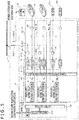
- FIG. 1 is a diagram depicting a configuration example (example 1) of the electricity supply-demand system Z according to the present embodiment.
- the electricity supply-demand system Z has a control device 1 and n numbers of electricity supply-demand facilities E (E1 to En).
- a vehicle V such as an electric-powered vehicle or a plug-in hybrid vehicle capable of storing power from outside in an electric storage device F is connected to each of the electricity supply-demand facilities E1 to En.
- Each of the electricity supply-demand facilities E1 to En has an internal-combustion power generating device 3, a DC/DC converter 4, a DC instrument joint JD, a DC/AC converter 5, and an AC instrument joint JA.
- a power synthesis/distribution device 2 is installed across the electricity supply-demand facilities E1 to En.
- the internal-combustion power generating device 3 is a power generating device capable of generating DC power, and is a diesel engine power generating device, a gas turbine power generating device, or the like configured with an AC/DC converter, an internal combustion engine, and a generator. It is noted that the internal-combustion power generating device 3 is connected to the power synthesis/distribution device 2 by a DC power supply device joint J41.
- a device, such as the internal-combustion power generating device 3, for supplying the DC power will be denoted as "DC power supply device" in the present description.
- the vehicle V is connected to each DC instrument joint JD.
- a customer load D is connected to each AC instrument joint JA via switches SW1 and SW2. Furthermore, a power system L is connected to the switch SW1.
- the power synthesis/distribution device 2 synthesizes the DC power generated (supplied) by the internal-combustion power generating devices 3, and distributes the DC power to the DC/DC converters 4 or the DC/AC converters 5.
- Each DC/DC converter 4 converts a voltage of the distributed power into a charge voltage or the like for the vehicle V (electric storage device F) connected thereto.
- the DC/DC converter 4 converts the power in such a manner that a current becomes a constant current before the charge voltage is equal to a predetermined charge voltage.
- the power synthesis/distribution device 2 exercises control over the current in advance such that the current does not exceed a rated value of the electric storage device F, as described later.
- the DC/DC converter 4 then converts the power in such a manner that the charge voltage becomes a constant voltage when the charge voltage is equal to the predetermined voltage.
- each DC/DC converter 4 is connected to the power synthesis/distribution device 2 and the DC instrument joint JD by DC/DC converter joints J21 and J22, respectively.
- the control device 1 has the charge voltage for switching the constant-current charging to the constant-voltage charging in registered information 131 (refer to FIG. 9 ). Furthermore, the control device 1 has information indicating end of the constant-voltage charging (threshold of a current value) in the registered information 131 (refer to FIG. 9 ). Such information is transmitted as control information from an output section 12 of the control device 1 to the power synthesis/distribution device 2 and the DC/DC converter 4. The power synthesis/distribution device 2 and the DC/DC converter 4 thereby control charging of the electric storage device F.
- the DC/DC converter 4 exercises similar control even in a case in which the charging method is the constant-voltage charging or the constant-current charging. It is noted that it is necessary to transmit a necessary charging power amount to the control device 1 in a case in which the charging method is the constant-current charging.
- control device 1 may automatically acquire information (identification information) related to what type of DC power supply device and what type of electric storage device F are connected via the Internet or the like or an operator may manually input such information to the control device 1.
- each DC/AC converter 5 converts direct-current power transmitted from the power synthesis/distribution device 2 into alternating-current power (for example, 100V, 50Hz) to be transmitted to the customer load D and the power system L.
- the DC/AC converters 5 desirably generate the alternating-current power in such a manner that alternating-current voltages to be generated are uniform in phase.
- the phase of the alternating-current voltages to be generated are based on control information from the control device 1.
- the control information is a duty cycle of a pulse for turning on an IGBT that is not depicted. It is noted that each DC/AC converter 5 is connected to the power synthesis/distribution device 2 and the AC instrument joint JA by DC/AC converter joints J11 and J12, respectively.
- transfer power referred to as “transfer power” or “system power”
- system power power of the power system L fluctuates or consumed power (necessary power) of the customer load D fluctuates.
- expected values of these fluctuations are input to the control device 1 via an input section 11 of the control device 1.
- a processing section 100 of the control device 1 re-computes the power to be supplied to the power system L and the customer load D on the basis of the expected values. This process will be described later.
- an element such as the electric storage device F, the customer load D, or the power system L connected to the DC/DC converter 4 or the DC/AC converter 5 is often referred to as “instrument.”
- an element such as the electric storage device F connected to the DC/DC converter 4 is often referred to as “DC instrument”
- an element such as the customer load D or the power system L connected to the DC/AC converter 5 is often referred to as "AC instrument.”
- each of the electricity supply-demand facilities E1 to En can select one of an AC supply mode for supplying only AC power from the AC instrument joint JA and a DC supply mode for supplying only the DC power from the DC instrument joint JD. Furthermore, each of the electricity supply-demand facilities E1 to En can select an AC/DC supply mode for supplying the AC power from the AC instrument joint JA and supplying the DC power from the DC instrument joint JD. By doing so, it is possible to prevent supply of power to an unnecessary instrument.
- the internal-combustion power generating devices 3 output different currents at the same voltage.
- a DC/DC converter may be provided between each internal-combustion power generating device 3 and the power synthesis/distribution device 2, and this DC/DC converter may perform voltage transformation.
- each internal-combustion power generating device 3, each DC/DC converter 4, and each DC/AC converter 5 are removable.
- the electricity supply-demand facility En from which the internal-combustion power generating device 3, the DC/DC converter 4, and the DC/AC converter 5 are removed also configures the electricity supply-demand system Z.
- FIG. 2 is a diagram depicting a configuration example (example 2) of the electricity supply-demand system Z according to the present embodiment.
- each internal-combustion power generating device 3 While the DC power generated by each internal-combustion power generating device 3 is charged into the electric storage device F of the vehicle V in the example of FIG. 1 , the DC power is supplied from each electric storage device F in the example of FIG. 2 . In other words, the electric storage device F is used as the DC power supply device.
- the DC power supplied from each electric storage device F is converted into DC power (voltage, current) generated by the internal-combustion power generating device 3 by the DC/DC converter 4 via the DC instrument joint JD, and then input to the power synthesis/distribution device 2.
- the power synthesis/distribution device 2 synthesizes the DC power input from the internal-combustion power generating devices 3 and the electric storage devices F, and distributes the DC power to the DC/AC converters 5.
- the electric storage device F mounted in each vehicle V is also used as one of the DC power supply devices.
- Examples of such a situation include a case in which power is supplied from the electric storage device F of an electric-powered vehicle or a plug-in hybrid vehicle serving as a power supply due to occurrence of a disaster.
- FIG. 3 is a diagram depicting a configuration example (example 3) of the electricity supply-demand system Z according to the present embodiment.
- a photovoltaic power generating device G1 is connected to the DC instrument joint JD of the electricity supply-demand facility En.
- a wind power generating device G2 is connected as an alternative to the customer load D depicted in FIG. 1 .
- the photovoltaic power generating device G1 functions as a DC power supply device.
- DC power supplied from the photovoltaic power generating device G1 is input to the DC/DC converter 4.
- the DC power is converted into the DC power (voltage, current) generated by the internal-combustion power generating device 3 by the DC/DC converter 4, and then input to the power synthesis/distribution device 2.
- the power synthesis/distribution device 2 synthesizes the DC power input from the internal-combustion power generating devices 3 and the photovoltaic power generating devices G1, and distributes the DC power to the DC/AC converters 5 and the other DC/DC converters 4.
- AC power supplied from the wind power generating device G2 is fed to the power system L via the switch SW2.
- the electricity supply-demand system Z may be configured such that the wind power generating device G2 is installed as an alternative to the photovoltaic power generating device G1 and the photovoltaic power generating device G1 is not provided, or that the photovoltaic power generating device G1 is installed as an alternative to the wind power generating device G2 and the wind power generating device G2 is not provided.
- the wind power generating device G2 as well as the photovoltaic power generating device G1 may be connected to one of the DC/DC converters 4.
- FIG. 4 is a diagram depicting a configuration example (example 4) of the electricity supply-demand system Z according to the present embodiment.
- an output side configuration of the power synthesis/distribution device 2 is similar to that in the example of FIG. 4 , while two internal-combustion power generating devices 3 are connected to an input side of the power synthesis/distribution device 2. Furthermore, the electricity supply-demand facilities E are not provided.
- n numbers of vehicles V and the two internal-combustion power generating devices 3 are connected to the power synthesis/distribution device 2; however, the present invention is not limited to this example. In other words, the present invention is applicable if the number of the internal-combustion power generating devices 3 connected to the power synthesis/distribution device 2 differs from the number of instruments connected to the output side of the power synthesis/distribution device 2.
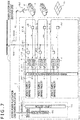
- FIG. 5 is a diagram depicting a configuration example (example 5) of the electricity supply-demand system Z according to the present embodiment.
- an AC load D1 other than the customer load D is connected to the DC/AC converter 5 of the electricity supply-demand facility En via the AC instrument joint JA.
- a DC load D2 other than the electric storage device F is connected to the DC/DC converter 4 via the DC instrument joint JD of the electricity supply-demand facility En. It is noted that the AC load D1 is contained in an AC instrument and the DC load D2 is contained in an DC instrument.
- FIG. 6 is a diagram depicting a configuration example (example 6) of the electricity supply-demand system Z according to the present embodiment.
- a plurality of DC/DC converters 4 and a plurality of DC instrument joints JD are installed in the electricity supply-demand facility En. Furthermore, the vehicles V (electric storage devices F) are connected to the DC instrument joints JD, respectively.
- FIG. 7 is a diagram depicting a configuration example (example 7) of the electricity supply-demand system Z according to the present embodiment.
- FIG. 7 depicts a case in which the power is supplied from the power system L, the wind power generating device G2, and the photovoltaic power generating device G1 to each electric storage device F.
- FIG. 7 differs from FIG. 3 in the following respects.
- a DC power supply route of the power system L that is, the wind power generating device G2 and the photovoltaic power generating device G1 -> the power synthesis/distribution device 2 -> the electric storage devices F, is configured.
- examples of a case of supply and demand of the power as depicted in FIG. 7 include a case in which the DC power is supplied to the electric storage devices F using excess power by, for example, renewable energy of wind power generation or the like. In such a case, it is unnecessary to connect the internal-combustion power generating devices 3 that separately require a fuel to the electricity supply-demand system Z and to operate the internal-combustion power generating device 3. In the example of FIG. 7 , therefore, each internal-combustion power generating device 3 is isolated from the power synthesis/distribution device 2.
- each internal-combustion power generating device 3 may be stopped without being isolated from the power synthesis/distribution device 2.
- output power from each internal-combustion power generating device 3 may be suppressed without isolating the internal-combustion power generating device 3 from the power synthesis/distribution device 2.
- FIG. 8 is a diagram depicting a configuration example (example 8) of an electricity supply-demand system Za according to the present embodiment.
- a power synthesis/distribution device 2a is installed across the electricity supply-demand facilities E1 to En on an output destination of the DC/DC converters 4.
- the DC instrument joints JD are installed on output destinations of the power synthesis/distribution device 2a, respectively. It is noted that in the example of FIG. 8 , each DC/DC converter 4 may be installed between the power synthesis/distribution device 2a and each DC instrument joint JD.
- the DC power synthesized and distributed once by the power synthesis/distribution device 2 and then distributed and output from each DC/DC converter 4 is synthesized and distributed again by the power synthesis/distribution device 2a.
- each power synthesis/distribution device 2 is the DC power.
- all the DC power output from the power synthesis/distribution device 2 is input to the power synthesis/distribution device 2a.
- the present invention is not limited to this example and part of the DC power output from the power synthesis/distribution device 2 may be input to the power synthesis/distribution device 2a.
- the power can be synthesized and distributed more minutely. It is noted that the power synthesis/distribution device 2a can be added later to the electricity supply-demand system Z as depicted in FIG. 1 .
- part of the configuration of one configuration example can be replaced by the configuration of the other configuration example, and the configuration of the other configuration example can be added to the configuration of one configuration example. Furthermore, for part of the configuration of each configuration example, addition, deletion, and replacement of the other configuration can be made.
- a DC instrument may be connected as an alternative to each vehicle V (electric storage device F).
- FIG. 9 is a diagram depicting an example of a configuration of the control device 1 according to the present embodiment. Reference is made to FIG. 1 , as appropriate.
- the control device 1 is a PC (Personal Computer), a PLC (Programmable Logic Controller), or the like.
- the control device 1 has a memory 111, a CPU (Central Processing Unit) 112, and a storage device 113 such as an HD (Hard Disk).
- the control device 1 further has an input device 114 such as a keyboard, a display device 115 such as a display, and a communication device 116 such as an NIC (Network Interface Card). It is noted that the input device 114 corresponds to the input section 11 of FIGS. 1 to 8 . In addition, the communication device 116 corresponds to the input section 11 and the output section 12 of FIGS. 1 to 8 .
- the registered information 131 is stored in the storage device 113.
- Information about each DC power supply device and each instrument connectable to the power synthesis/distribution device 2 is stored in the registered information 131 in advance in such a manner that the DC power supply device corresponds to identification information about the DC power supply device and the instrument corresponds to identification information about the instrument.
- the information is rated output power or the like of each internal-combustion power generating device 3.
- each instrument is the electric storage device F of constant-current and constant-voltage charging type
- a constant current value, a constant voltage value, a charge voltage value for switching to the constant-voltage charging, a current value for ending the constant-voltage charging, and the like are stored in the registered information 131 to correspond to identification information about the electric storage device F.
- Having such registered information 131 enables the control device 1 to exercise concentrated control over the electricity supply-demand system Z. This can facilitate managing the control.
- a program stored in the storage device 113 is load into the memory 111.
- executing the loaded program by the CPU 112 embodies the processing section 100 as well as a distribution setting section 101, a mode setting section 102, a change processing section 103, an abnormality processing section 104, and a fluctuation processing section 105 included in the processing section 100.
- the distribution setting section 101 computes the power (distributed power) output (distributed) from each DC/DC converter 4 or each DC/AC converter 5 on the basis of the registered information 131 and the like. In addition, the distribution setting section 101 controls the power synthesis/distribution device 2, each DC/DC converter 4, each DC/AC converter 5, and the like on the basis of the generated distributed power.
- the mode setting section 102 switches a supply mode over among the DC supply mode, the AC supply mode, and AC/DC supply mode described above in each of the electricity supply-demand facilities E.
- the change processing section 103 re-computes supply and distribution of the power when an instrument (or DC power supply device) changes.
- the abnormality processing section 104 re-computes the supply and distribution of the power when an abnormality in a DC power supply devices (or instruments) is detected.
- the fluctuation processing section 105 re-computes the supply and distribution of the power when load power of the customer load D fluctuates.
- FIG. 10 is a diagram depicting a configuration example of the power synthesis/distribution device 2 used in the present embodiment. Reference is made to FIG. 1 , as appropriate.
- the power synthesis/distribution device 2 has a synthesis section 21 and a distribution section 22.
- a plurality of interconnection lines A1 are disposed in parallel in the synthesis section 21.
- Each interconnection line A1 has a power generating device joint J51, a switch SW1, and a backflow prevention diode D11 in an order from an internal-combustion power generating device (power generating device) 3 side.
- One internal-combustion power generating device 3 is connected to the power generating device joint J51.
- the interconnection lines A1 merge into an interconnection line A2.
- a backflow prevention diode D12 is similarly provided on the interconnection line A2.
- the switch SW11 is a switch for performing connection interruption and the like of each internal-combustion power generating device 3.
- the connection interruption of the internal-combustion power generating device 3 is performed at a time of, for example, occurrence of an abnormality in the internal-combustion power generating device 3 (details will be described later).
- a plurality of AC interconnection lines A31 and a plurality of DC interconnection lines A32 are disposed in parallel in the distribution section 22. Each of the AC interconnection lines A31 and the DC interconnection lines A32 is connected to the interconnection line A2.
- Each AC interconnection line A31 has a switch SW21 and an AC joint J52 in the order from the internal-combustion power generating device (power generating device) 3 side.
- Each DC/AC converter 5 is connected to the AC joint J52.
- the switch SW21 is a switch for connection/interruption between each DC/AC converter 5 and the power synthesis/distribution device 2.
- each DC interconnection line A32 has a variable resistance R, switches SW22 and SW23, backflow prevention diodes D21 and D22, a switch SW24, and a DC joint J53 in the order from the internal-combustion power generating device (power generating device) 3 side.
- variable resistance R on the DC interconnection line A32 is used to control the current supplied to each DC/DC converter 4.
- the current can be determined by an input impedance of each DC/DC converter 4.
- making the variable resistance R variable by the control information transmitted from the power synthesis/distribution device 2 enables control over the current carried to each DC/DC converter 4.
- the switch SW22 is a switch for connection/interruption between each DC/DC converter 4 and the instrument connected to the DC/DC converter 4.
- the switches SW23 and SW24 are switches for switching connection over between the diodes D21 and D22. It is noted herein that the diode D21 is connected at a time of carrying the current to the instrument. At a time of, for example, charging the electric storage device F as depicted in FIG. 1 , the diode D21 is connected.
- the diode D22 is connected when the current is carried from the instrument.
- the diode D22 is connected in a case of using each electric storage device F as the DC power supply device as depicted in FIG. 2 or in a case of connecting the photovoltaic power generating device G1 in the electricity supply-demand facility En of FIG. 3 .
- Each DC/DC converter 4 is connected to the DC joint J53.
- toggle switches, push button switches, relays, or the like are used as the switches SW11 and SW21 to SW24.
- the switches SW11 and SW21 to SW24 are the toggle switches or the push button switches
- switching is manually performed.
- the switches SW11 and SW21 to SW24 are the relays
- switching can be performed in response to a command from the control device 1.
- the switches SW11 and SW21 to SW24 are each preferably configured with the relay and used to perform switching in response to a command from the control device 1.
- the supply mode is switched to the AC supply mode when the switch SW21 is turned on and the switch SW22 is turned off.
- the supply mode is switched to the DC supply mode when the switch SW21 is turned off and the switch SW22 is turned on.
- the supply mode is switched to the AC/DC supply mode when both of the switches SW21 and SW22 are turned on.
- the switches SW21 and SW22 are controlled to be turned on or off by the control device 1 while the operator can manually turn on or off the switches SW21 and SW22.
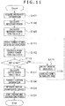
- FIG. 11 is a flowchart depicting process procedures performed by the electricity supply-demand system Z at an initial time (at a time of installing devices).
- the distribution setting section 101 of the control device 1 acquires identification information (instrument information) about each of the instruments connected to the AC instrument joints JA and the DC instrument joints JD (S101).
- the instruments include not only each electric storage device F of FIG. 1 but also the power system L, the customer load D, the AC load D1 and the DC load D2 depicted in FIG. 5 , and the like.
- the distribution setting section 101 of the control device 1 computes necessary power that is the power necessary for each instrument on the basis of the acquired identification information (S102). Specifically, the distribution setting section 101 computes the necessary power for each instrument on the basis of the registered information 131 about each instrument stored in the storage device 113 of the control device 1 and the identification information about each currently connected instrument. For example, in a case in which the instrument is each electric storage device F of the constant-current constant-voltage charging type, the constant current value, the constant voltage value, the charge voltage value for switching to the constant-voltage charging, time of performing the constant-voltage charging, and the like are stored in the registered information 131. The distribution setting section 101 computes the necessary power at each time on the basis of these pieces of information.
- the distribution setting section 101 then computes a necessary power total value (M1) that is a total value of the necessary power (S103). It is noted that in a case in which the necessary power changes over time such as that of the electric storage device F of the constant-current constant-voltage charging type, the distribution setting section 101 computes the necessary power total value (M1) on the basis of a maximum value of the necessary power.
- the distribution setting section 101 computes a total value of AC necessary power necessary for each AC instrument. Furthermore, the distribution setting section 101 computes a total value of DC necessary power necessary for each DC instrument. The distribution setting section 101 then computes a sum of the total value of the AC necessary power and the total value of the DC necessary power as the necessary power total value (M1).
- the distribution setting section 101 determines the number of DC power supply devices to be activated on the basis of the necessary power total value (M1) (Sill), and computes a rated output power total value (M2) of the DC power supply devices to be used (S112). At this time, the distribution setting section 101 may determine the DC power supply devices to be activated and the number of the DC power supply devices so that the rated output power total value (M2) is as close to the necessary power total value (M1) as possible. By doing so, it is possible to suppress generation of unnecessary power.
- the distribution setting section 101 determines whether the rated output power total value (M2) computed in Step S112 is equal to or greater than the necessary power total value (M1) computed in Step S103 (M1 ⁇ M2) (S113).
- the distribution setting section 101 instructs the operator (user) to add a DC power supply device (S114).
- This instruction is made by, for example, displaying the necessary power and the like on the display device 115 of the control device 1 or the like.
- the DC power supply device which is specifically the internal-combustion power generating device 3
- the distribution setting section 101 returns the process to S111, re-determines the DC power supply devices to be activated and the number of DC power supply devices, and recomputes the rated output power total value (M2).
- the distribution setting section 101 computes an output power target value of each DC power supply device (S121).
- the distribution setting section 101 transmits the control information to the power synthesis/distribution device 2, each DC/DC converter 4, and each DC/AC converter 5 (S122). Current information, voltage transformation information, and the like are stored in the control information.
- each DC power supply device is activated (S123). Feeding and distribution of the power is thereby started (S124).
- Step S124 the following processes are performed.
- the DC power supply devices may be activated either manually or by the control device 1. Furthermore, before activation of the DC power supply devices, the switch SW11 of FIG. 10 (as well as the switches SW22 to SW24 as needed) is turned on or off, thereby establishing connection to the power synthesis/distribution device 2.
- the distribution setting section 101 recomputes the rated output power total value (M2) of the DC power supply devices (combination of the DC power supply devices).
- the present invention is not limited to this example and the distribution setting section 101 may recomputes the rated output power total value (M2) of the DC power supply devices (combination of the DC power supply devices) even in a case in which the rated output power total value (M2) of the DC power supply devices exceeds the necessary power total value (M1).
- the distribution setting section 101 may recompute a combination of the DC power supply devices until the rated output power total value (M2) of the DC power supply devices is equal to the same value as that when the rated output power total value (M2) does not exceed the necessary power total value (M1).
- FIG. 12 is a flowchart depicting process procedures performed by the electricity supply-demand system Z when an instrument connected to a DC instrument joint JD changes. It is noted that supply of power by each DC power supply device is not stopped during a process of FIG. 12 .
- the change processing section 103 of the control device 1 determines whether a change in the instrument connected to each DC device joint JD has occurred (S201). Whether occurrence of the change in the instrument is detected by acquiring the identification information about each instrument by the change processing section 103.
- Step S201 In a case of no change in the instrument as a result of Step S201 (S201 -> No), the change processing section 103 returns the process to Step S201.
- Step S201 the change processing section 103 performs a power distribution process (S211). Since the power distribution process is similar to the process in Steps S101 to S124 of FIG. 11 , description thereof will be omitted. It is noted that supply of power is not stopped during the process of FIG. 12 .
- the change processing section 103 stops an unnecessary DC power supply device (internal-combustion power generating device 3) in a case in which the unnecessary DC power supply device is present due to occurrence of the change in instrument.
- an unnecessary DC power supply device internal-combustion power generating device 3
- FIG. 13 is a flowchart depicting process procedures performed by the electricity supply-demand system Z when an abnormality occurs in a DC power supply device. It is noted that the supply of power by each DC power supply device is not stopped during a process of FIG. 13 .
- the abnormality processing section 104 of the control device 1 determines whether an abnormality has occurred in any of the DC power supply devices (S301). Abnormality of the DC power supply device is detected by, for example, detecting an abnormal current degradation of the DC power supply device.
- Step S301 In a case in which an abnormality has not occurred in any of the DC power supply devices as a result of Step S301 (S301 -> No), the abnormality processing section 104 returns the process to Step S301.
- the abnormality processing section 104 identifies the DC power supply device in which the abnormality occurs (S302).
- the abnormality processing section 104 instructs the operator to connect the DC power supply device (internal-combustion power generating device 3), which has the rated output power equal to or higher than that of the DC power supply device in which the abnormality occurs, to the power synthesis/distribution device 2 (S303). In other words, the abnormality processing section 104 notifies the operator to replace the DC power supply device from which the abnormality has been detected by a normal DC power supply device.
- the abnormality processing section 104 may display the rated output power of the DC power supply device in which the abnormality occurs on the display device 115.
- the operator additionally connects the DC power supply device having the rated output power equal to or higher than that of the DC power supply device in which the abnormality occurs (S304). It is noted that the number of DC power supply devices to be additionally connected is not limited to one and a plurality of DC power supply devices may have the rated output power equal to or higher than that of the DC power supply device in which the abnormality occurs.
- the abnormality processing section 104 performs the power distribution process (S311). Since the power distribution process is similar to the process in Steps S101 to S121 of FIG. 11 , description thereof will be omitted.
- the additionally connected DC power supply device is connected by the switch SW11 of FIG. 10 (as well as the switch SW22 according to circumstances), and the additionally connected DC power supply device is activated (S321).
- the abnormality processing section 104 recomputes the supply and distribution of the power at the time of occurrence of an abnormality in the DC power supply device.
- FIG. 14 is a flowchart depicting process procedures performed by the electricity supply-demand system Z when a fluctuation occurs in system power or load power (consumed power of the customer load D).
- the fluctuation processing section 105 of the control device 1 determines whether an advance notice of a fluctuation in the system power or the load power has been received (S401).
- the advance notice of a fluctuation include an advance notice to the effect that in how many minutes the system power or the load power changes. To take an example, it is expected up to what °C at what time a temperature rises and a usage rate of air conditioners rises in summer, so that a fluctuation in the system power is expected.
- Step S401 In a case in which the advance notice has not been received as a result of Step S401 (S401 -> No), the fluctuation processing section 105 returns the process to Step S401.
- the fluctuation processing section 105 acquires an expected value from the system power or the customer load D (S402). In the example in which the usage rate of air conditioners rises in summer described above, how much power is expected to be necessary from past experience is acquired as the expected value.
- Such an expected value is transmitted to the control device 1 via the Internet or the like.
- the fluctuation processing section 105 performs the power distribution process (S411). Since the power distribution process is similar to the process in Steps S101 to S124 of FIG. 11 , description thereof will be omitted.
- the present embodiment is characterized in that synthesis and distribution are performed on the basis of the DC power. This makes it possible to facilitate synthesizing and distributing the power.
- the DC power distributed and output from the power synthesis/distribution device 2 is subjected to voltage transformation by each DC/DC converter 4 or converted into the AC power by each DC/AC converter 5. It is thereby possible to connect both the DC instruments and the AC instruments.
- each internal-combustion power generating device 3 power generation
- each electric storage device F both of a power generation function and a load function
- each DC/DC converter 4 and each DC/AC converter 5 makes it possible to improve a degree of freedom of a combination of the DC power supply devices and the instruments.
- the DC load D2 can be connected to the DC instrument joint JD as an alternative to the electric storage device F, or the AC load D1 can be connected to the AC instrument joint JA as depicted in FIG. 5 .
- providing each DC/DC converter 4 and each DC/AC converter 5 makes it possible to transform the voltage in response to the DC load D2 connected to the DC instrument joint JD, the AC load D1, or the like. In this way, the electricity supply-demand system Z of the present embodiment can easily change a use application.
- setting the output power target value to each DC power supply device facilitates managing the DC power supply device.
- each internal-combustion power generating device 3 as one of the DC power supply devices makes the supply of the DC power convenient and easy.
- adjusting power is necessary for relaxing a supply-side power fluctuation by renewable energy, a demand-side power fluctuation by boost chargers, and the like.
- performing the process of FIG. 14 makes it possible to supply backup power of the wind power generation or the like even in a case, for example, in which a fluctuation or the like occurs in a power generation amount of the wind power generating device G2 or the like supplying the power to the power system L. In other words, it is possible to compensate for the supply of power for stable electricity supply to an electricity system using the renewable energy.
- control device 1 may perform the processes of FIGS. 11 to 14 in each of the DC supply mode, the AC/DC supply mode, and the AC/DC supply mode described above. Needless to say, the control device 1 calculates the necessary power only for each of the DC instruments in the DC supply mode, calculates the necessary power only for each of the AC instruments in the AC supply mode, and calculates the necessary power for each of the DC instruments and the AC instruments in the AC/DC supply mode, and performs distribution of the power.
- a fuel cell, an AC power generating device + an AC/DC converter, or the like may be used as an alternative to each internal-combustion power generating device 3 in the present embodiment.
- the present invention is not limited to the embodiment described above but encompasses various modifications.
- the above embodiment has been described in detail for describing the present invention so that the present invention is easy to understand.
- the present invention is not always limited to what has all the configurations described so far.
- the configurations, the functions, the processing sections 100 to 105, the storage device 113, and the like described above may be realized by hardware by, for example, designing part or all thereof with integrated circuits.
- the configurations, the functions, and the like described above may be realized by software by causing a processor such as the CPU 112 to interpret and execute programs that realize the functions.
- Information in programs, tables, files, and the like for realizing the functions can be stored in a storage device such as the memory 111 or an SSD (Solid State Drive), or in a recording medium such as an IC (Integrated Circuit) card, an SD (Secure Digital) card, or a DVD (Digital Versatile Disc).
- control lines or information lines considered to be necessary for the description are illustrated and all the control lines or the information lines are not always illustrated in terms of a product. In actuality, it may be assumed that almost all the configurations are mutually connected.
Landscapes
- Engineering & Computer Science (AREA)
- Power Engineering (AREA)
- Transportation (AREA)
- Mechanical Engineering (AREA)
- Direct Current Feeding And Distribution (AREA)
- Supply And Distribution Of Alternating Current (AREA)
Abstract
Description
- The present invention relates to an electricity supply-demand system, a control device, and an electricity supply-demand method.
- Installation of power generating devices by internal-combustion power (hereinafter, referred to as "internal-combustion power generating devices) for use in power compensation facilities, in-house power generation facilities at time of emergency, and the like for the purpose of stable supply of electricity by renewable energy is growing. Furthermore, it is predicted that needs of DC power supply devices such as internal-combustion power generating devices more and more rises with a view to supply of power to controlled regions.
-
Patent Document 1 discloses, for example, a method of controlling operation of power generation facility, the method "including: a priority setting step of setting priorities for a plurality of power generation means on the basis of index values correlated with operational states of the plurality of power generation means; an operation number determination step of determining the number of power generation means to be operated on the basis of a total power generation amount target value of the power generation facility; a power generation means operation step of starting or stopping the power generation means as needed, in such a manner that only the determined number of power generation means to be operated are operated on the basis of the priorities among the plurality of power generation means; and a switching time determination step of determining a time at which a target power generation amount and a scheduled variation, within a predetermined period in the power generation facility, calculated from a power generation schedule pattern for the predetermined period are each equal to or greater than a threshold Ptgt_th and equal to or smaller than a threshold Cth, as a priority switching time at which new priorities are set in the priority setting step in place of the last priorities," and a device for controlling operation of a power generation facility. - Patent Document 1:
JP-2016-82740-A - However, the conventional DC power supply devices have been installed for a single use application. Owing to this, when a DC power supply device installed for one use application is used for another use application, it is necessary to revise connection to instruments, connection to systems, and the like. Furthermore, a plurality of DC power supply devices are often configured to be connected in parallel for ensuring high output power. When the use application is to be changed with such a configuration, more complicated work is required.
- With the technique described in
Patent Document 1, for example, only a gas engine power generation facility and/or a diesel power generation facility is configured for use in supply of power. Owing to this, the technique described inPatent Document 1 provides a system only for continuous use for one use application once the system is installed for the use application. - Specifically, with the technique described in
Patent Document 1, power generated in a plurality of gas engine power generation facilities and/or diesel power generation facilities are synthesized and output. It is noted herein that with the technique described inPatent Document 1, in a case in which necessary power falls below a total power generation amount and power generation facilities unnecessary to activate are present, the power generation facilities remain stopped. Owing to this, it is impossible to make effective use of the power generation facilities. - The present invention has been achieved in light of such circumstances, and an object of the present invention is to realize flexible supply of power.
- To solve the problems, the present invention includes: a plurality of DC power supply device joints connecting DC power supply devices that supply DC power; a power synthesis/distribution device connected to the DC power supply device joints, synthesizing the DC power input from the DC power supply device joints, and distributing the synthesized DC power; at least one DC/AC converter joint that connects a DC/AC converter to the power synthesis/distribution device; at least one DC/DC converter joint that connects a DC/DC converter to the power synthesis/distribution device; at least one AC instrument joint provided in rear of the DC/AC converter joint, AC instruments being connected to the at least one AC instrument joint; at least one DC instrument joint provided in rear of the DC/DC converter joint, DC instruments being connected to the at least one DC/DC converter joint; and a control device that computes and determines a number of the DC power supply devices to be activated in such a manner that a power amount is closer to a necessary power total value for an instrument connected to at least one of the DC instrument joint and the AC instrument joint in a case of a change in the connected instrument, and that exercises control over synthesis of the DC power and distribution of the DC power to the AC instrument joint and the DC instrument joint by controlling at least one of the power synthesis/distribution device, the DC/AC converter, and the DC/DC converter, and that supplies necessary power necessary for instruments connected to at least one of the AC instrument joint and the DC instrument joint without stopping supplying the necessary power.
- The other means for solving the problems will be described later in embodiments.
- According to the present invention, it is possible to realize flexible supply of power.
-
-
FIG. 1 is a diagram depicting a configuration example (example 1) of an electricity supply-demand system Z according to the present embodiment. -
FIG. 2 is a diagram depicting a configuration example (example 2) of the electricity supply-demand system Z according to the present embodiment. -
FIG. 3 is a diagram depicting a configuration example (example 3) of the electricity supply-demand system Z according to the present embodiment. -
FIG. 4 is a diagram depicting a configuration example (example 4) of the electricity supply-demand system Z according to the present embodiment. -
FIG. 5 is a diagram depicting a configuration example (example 5) of the electricity supply-demand system Z according to the present embodiment. -
FIG. 6 is a diagram depicting a configuration example (example 6) of the electricity supply-demand system Z according to the present embodiment. -
FIG. 7 is a diagram depicting a configuration example (example 7) of an electricity supply-demand system Za according to the present embodiment. -
FIG. 8 is a diagram depicting a configuration example (example 8) of the electricity supply-demand system Za according to the present embodiment. -
FIG. 9 is a diagram depicting a configuration example of acontrol device 1 according to the present embodiment. -
FIG. 10 is a diagram depicting a configuration example of a power synthesis/distribution device used in the present embodiment. -
FIG. 11 is a flowchart depicting process procedures performed by the electricity supply-demand system Z at an initial time (at a time of installing instruments). -
FIG. 12 is a flowchart depicting process procedures performed by the electricity supply-demand system Z when an instrument connected to a DC instrument joint changes. -
FIG. 13 is a flowchart depicting process procedures performed by the electricity supply-demand system Z when an abnormality occurs in a DC power supply device. -
FIG. 14 is a flowchart depicting process procedures performed by the electricity supply-demand system Z when a fluctuation occurs in system power or load power (consumed power of a customer load D). - A mode for carrying out the present invention (referred to as "embodiment") will next be described with reference to the drawings as appropriate.
- Examples of a configuration of an electricity supply-demand system Z according to the present embodiment will first be described with reference to
FIGS. 1 to 8 . It is noted that similar constituent elements are denoted by the same reference characters and description thereof will be omitted inFIGS. 1 to 8 . Furthermore, inFIGS. 1 to 8 , a solid-line arrow indicates a flow of power (current). -
FIG. 1 is a diagram depicting a configuration example (example 1) of the electricity supply-demand system Z according to the present embodiment. - The electricity supply-demand system Z has a
control device 1 and n numbers of electricity supply-demand facilities E (E1 to En). - A vehicle V such as an electric-powered vehicle or a plug-in hybrid vehicle capable of storing power from outside in an electric storage device F is connected to each of the electricity supply-demand facilities E1 to En.
- Each of the electricity supply-demand facilities E1 to En has an internal-combustion
power generating device 3, a DC/DC converter 4, a DC instrument joint JD, a DC/AC converter 5, and an AC instrument joint JA. - Furthermore, a power synthesis/
distribution device 2 is installed across the electricity supply-demand facilities E1 to En. - The internal-combustion
power generating device 3 is a power generating device capable of generating DC power, and is a diesel engine power generating device, a gas turbine power generating device, or the like configured with an AC/DC converter, an internal combustion engine, and a generator. It is noted that the internal-combustionpower generating device 3 is connected to the power synthesis/distribution device 2 by a DC power supply device joint J41. A device, such as the internal-combustionpower generating device 3, for supplying the DC power will be denoted as "DC power supply device" in the present description. - The vehicle V is connected to each DC instrument joint JD.
- In addition, a customer load D is connected to each AC instrument joint JA via switches SW1 and SW2. Furthermore, a power system L is connected to the switch SW1.
- The power synthesis/
distribution device 2 synthesizes the DC power generated (supplied) by the internal-combustionpower generating devices 3, and distributes the DC power to the DC/DC converters 4 or the DC/AC converters 5. - Each DC/
DC converter 4 converts a voltage of the distributed power into a charge voltage or the like for the vehicle V (electric storage device F) connected thereto. In a case in which a charging method of charging the electric storage device F with the power is constant-current constant-voltage charging, the DC/DC converter 4 converts the power in such a manner that a current becomes a constant current before the charge voltage is equal to a predetermined charge voltage. It is noted that the power synthesis/distribution device 2 exercises control over the current in advance such that the current does not exceed a rated value of the electric storage device F, as described later. The DC/DC converter 4 then converts the power in such a manner that the charge voltage becomes a constant voltage when the charge voltage is equal to the predetermined voltage. It is noted that each DC/DC converter 4 is connected to the power synthesis/distribution device 2 and the DC instrument joint JD by DC/DC converter joints J21 and J22, respectively. - In this case, the
control device 1 has the charge voltage for switching the constant-current charging to the constant-voltage charging in registered information 131 (refer toFIG. 9 ). Furthermore, thecontrol device 1 has information indicating end of the constant-voltage charging (threshold of a current value) in the registered information 131 (refer toFIG. 9 ). Such information is transmitted as control information from anoutput section 12 of thecontrol device 1 to the power synthesis/distribution device 2 and the DC/DC converter 4. The power synthesis/distribution device 2 and the DC/DC converter 4 thereby control charging of the electric storage device F. - It is noted that the DC/
DC converter 4 exercises similar control even in a case in which the charging method is the constant-voltage charging or the constant-current charging. It is noted that it is necessary to transmit a necessary charging power amount to thecontrol device 1 in a case in which the charging method is the constant-current charging. - It is noted that the
control device 1 may automatically acquire information (identification information) related to what type of DC power supply device and what type of electric storage device F are connected via the Internet or the like or an operator may manually input such information to thecontrol device 1. - On the other hand, each DC/
AC converter 5 converts direct-current power transmitted from the power synthesis/distribution device 2 into alternating-current power (for example, 100V, 50Hz) to be transmitted to the customer load D and the power system L. At this time, the DC/AC converters 5 desirably generate the alternating-current power in such a manner that alternating-current voltages to be generated are uniform in phase. The phase of the alternating-current voltages to be generated are based on control information from thecontrol device 1. In a case, for example, in which each DC/AC converter 5 has a PWM-controlled inverter circuit, the control information is a duty cycle of a pulse for turning on an IGBT that is not depicted. It is noted that each DC/AC converter 5 is connected to the power synthesis/distribution device 2 and the AC instrument joint JA by DC/AC converter joints J11 and J12, respectively. - It is often predicted that power (referred to as "transfer power" or "system power") of the power system L fluctuates or consumed power (necessary power) of the customer load D fluctuates. In such a case, expected values of these fluctuations are input to the
control device 1 via aninput section 11 of thecontrol device 1. Aprocessing section 100 of thecontrol device 1 re-computes the power to be supplied to the power system L and the customer load D on the basis of the expected values. This process will be described later. - It is noted that an element such as the electric storage device F, the customer load D, or the power system L connected to the DC/
DC converter 4 or the DC/AC converter 5 is often referred to as "instrument." In addition, an element such as the electric storage device F connected to the DC/DC converter 4 is often referred to as "DC instrument," and an element such as the customer load D or the power system L connected to the DC/AC converter 5 is often referred to as "AC instrument." - It is noted herein that each of the electricity supply-demand facilities E1 to En can select one of an AC supply mode for supplying only AC power from the AC instrument joint JA and a DC supply mode for supplying only the DC power from the DC instrument joint JD. Furthermore, each of the electricity supply-demand facilities E1 to En can select an AC/DC supply mode for supplying the AC power from the AC instrument joint JA and supplying the DC power from the DC instrument joint JD. By doing so, it is possible to prevent supply of power to an unnecessary instrument.
- It is noted that the internal-combustion
power generating devices 3 output different currents at the same voltage. In a case in which the internal-combustionpower generating devices 3 output different voltages, then a DC/DC converter may be provided between each internal-combustionpower generating device 3 and the power synthesis/distribution device 2, and this DC/DC converter may perform voltage transformation. - It is noted that providing the electricity supply-demand facilities E1 to En enable management based on numbering, as depicted in
FIG. 1 . - Furthermore, each internal-combustion
power generating device 3, each DC/DC converter 4, and each DC/AC converter 5 are removable. The electricity supply-demand facility En from which the internal-combustionpower generating device 3, the DC/DC converter 4, and the DC/AC converter 5 are removed also configures the electricity supply-demand system Z. -
FIG. 2 is a diagram depicting a configuration example (example 2) of the electricity supply-demand system Z according to the present embodiment. - While the DC power generated by each internal-combustion
power generating device 3 is charged into the electric storage device F of the vehicle V in the example ofFIG. 1 , the DC power is supplied from each electric storage device F in the example ofFIG. 2 . In other words, the electric storage device F is used as the DC power supply device. - The DC power supplied from each electric storage device F is converted into DC power (voltage, current) generated by the internal-combustion
power generating device 3 by the DC/DC converter 4 via the DC instrument joint JD, and then input to the power synthesis/distribution device 2. The power synthesis/distribution device 2 synthesizes the DC power input from the internal-combustionpower generating devices 3 and the electric storage devices F, and distributes the DC power to the DC/AC converters 5. - In other words, in the example of
FIG. 2 , the electric storage device F mounted in each vehicle V is also used as one of the DC power supply devices. Examples of such a situation include a case in which power is supplied from the electric storage device F of an electric-powered vehicle or a plug-in hybrid vehicle serving as a power supply due to occurrence of a disaster. -
FIG. 3 is a diagram depicting a configuration example (example 3) of the electricity supply-demand system Z according to the present embodiment. - In the example of
FIG. 3 , a photovoltaic power generating device G1 is connected to the DC instrument joint JD of the electricity supply-demand facility En. In addition, a wind power generating device G2 is connected as an alternative to the customer load D depicted inFIG. 1 . - It is noted herein that the photovoltaic power generating device G1 functions as a DC power supply device.
- In other words, DC power supplied from the photovoltaic power generating device G1 is input to the DC/
DC converter 4. In addition, the DC power is converted into the DC power (voltage, current) generated by the internal-combustionpower generating device 3 by the DC/DC converter 4, and then input to the power synthesis/distribution device 2. The power synthesis/distribution device 2 synthesizes the DC power input from the internal-combustionpower generating devices 3 and the photovoltaic power generating devices G1, and distributes the DC power to the DC/AC converters 5 and the other DC/DC converters 4. - Furthermore, AC power supplied from the wind power generating device G2 is fed to the power system L via the switch SW2.
- It is noted that in the example of
FIG. 3 , the electricity supply-demand system Z may be configured such that the wind power generating device G2 is installed as an alternative to the photovoltaic power generating device G1 and the photovoltaic power generating device G1 is not provided, or that the photovoltaic power generating device G1 is installed as an alternative to the wind power generating device G2 and the wind power generating device G2 is not provided. Alternatively, the wind power generating device G2 as well as the photovoltaic power generating device G1 may be connected to one of the DC/DC converters 4. -
FIG. 4 is a diagram depicting a configuration example (example 4) of the electricity supply-demand system Z according to the present embodiment. - In the example of
FIG. 4 , an output side configuration of the power synthesis/distribution device 2 is similar to that in the example ofFIG. 4 , while two internal-combustionpower generating devices 3 are connected to an input side of the power synthesis/distribution device 2. Furthermore, the electricity supply-demand facilities E are not provided. - It is noted that in the example of
FIG. 4 , n numbers of vehicles V and the two internal-combustionpower generating devices 3 are connected to the power synthesis/distribution device 2; however, the present invention is not limited to this example. In other words, the present invention is applicable if the number of the internal-combustionpower generating devices 3 connected to the power synthesis/distribution device 2 differs from the number of instruments connected to the output side of the power synthesis/distribution device 2. -
FIG. 5 is a diagram depicting a configuration example (example 5) of the electricity supply-demand system Z according to the present embodiment. - In the example of
FIG. 5 , an AC load D1 other than the customer load D is connected to the DC/AC converter 5 of the electricity supply-demand facility En via the AC instrument joint JA. Furthermore, a DC load D2 other than the electric storage device F is connected to the DC/DC converter 4 via the DC instrument joint JD of the electricity supply-demand facility En. It is noted that the AC load D1 is contained in an AC instrument and the DC load D2 is contained in an DC instrument. -
FIG. 6 is a diagram depicting a configuration example (example 6) of the electricity supply-demand system Z according to the present embodiment. - In the example of
FIG. 6 , a plurality of DC/DC converters 4 and a plurality of DC instrument joints JD are installed in the electricity supply-demand facility En. Furthermore, the vehicles V (electric storage devices F) are connected to the DC instrument joints JD, respectively. -
FIG. 7 is a diagram depicting a configuration example (example 7) of the electricity supply-demand system Z according to the present embodiment. -
FIG. 7 depicts a case in which the power is supplied from the power system L, the wind power generating device G2, and the photovoltaic power generating device G1 to each electric storage device F. -
FIG. 7 differs fromFIG. 3 in the following respects. - (1) Each internal-combustion power generating device (DC power supply device) 3 is isolated from the power synthesis/
distribution device 2. - (2) Similarly to
FIG. 3 , the switch SW1 disposed between the electricity supply-demand system Z and the power system L is turned on. Similarly, the switch SW2 disposed between the electricity supply-demand system Z and the wind power generating device G2 is turned on. It is to be noted, however, that the AC power is fed from the power system L and the wind power generating device G2. - (3) The power fed from the power system L and the wind power generating device G2 is converted into desired DC power by the DC/
AC converter 5. In addition, after the power is converted into the desired DC power by the DC/DC converter 4, the DC power is supplied to the electric storage device F of each vehicle V and the like via synthesis and distribution by operating the power synthesis/distribution device 2. - (4) In addition, the DC power generated by the photovoltaic power generating device G1 is also synthesized and distributed by the power synthesis/
distribution device 2 and fed to each electric storage device F and the like. - By doing so, a DC power supply route of the power system L, that is, the wind power generating device G2 and the photovoltaic power generating device G1 -> the power synthesis/distribution device 2 -> the electric storage devices F, is configured.
- It is conceivable that examples of a case of supply and demand of the power as depicted in
FIG. 7 include a case in which the DC power is supplied to the electric storage devices F using excess power by, for example, renewable energy of wind power generation or the like. In such a case, it is unnecessary to connect the internal-combustionpower generating devices 3 that separately require a fuel to the electricity supply-demand system Z and to operate the internal-combustionpower generating device 3. In the example ofFIG. 7 , therefore, each internal-combustionpower generating device 3 is isolated from the power synthesis/distribution device 2. - It is noted that each internal-combustion
power generating device 3 may be stopped without being isolated from the power synthesis/distribution device 2. Alternatively, in a case in which only the power supplied from the power line L and the wind power generating device G2 is insufficient, output power from each internal-combustionpower generating device 3 may be suppressed without isolating the internal-combustionpower generating device 3 from the power synthesis/distribution device 2. - By doing so, it is possible to supply the excess power of the power line L and the wind power generating device G2 of
FIG. 7 to the electricity supply-demand system Z. Furthermore, leaving unused (or suppressed in output power) the internal-combustionpower generating devices 3 unnecessary to use enables saving of the fuel of the internal-combustionpower generating devices 3. -
FIG. 8 is a diagram depicting a configuration example (example 8) of an electricity supply-demand system Za according to the present embodiment. - In the example of
FIG. 8 , a power synthesis/distribution device 2a is installed across the electricity supply-demand facilities E1 to En on an output destination of the DC/DC converters 4. In addition, the DC instrument joints JD are installed on output destinations of the power synthesis/distribution device 2a, respectively. It is noted that in the example ofFIG. 8 , each DC/DC converter 4 may be installed between the power synthesis/distribution device 2a and each DC instrument joint JD. - In other words, in the example of
FIG. 8 , the DC power synthesized and distributed once by the power synthesis/distribution device 2 and then distributed and output from each DC/DC converter 4 is synthesized and distributed again by the power synthesis/distribution device 2a. - While the two power synthesis/
distribution devices FIG. 8 , three or more power synthesis/distribution devices may be installed. It is to be noted, however, that the power input to and output from each power synthesis/distribution device 2 is the DC power. - Furthermore, in the example of
FIG. 8 , all the DC power output from the power synthesis/distribution device 2 is input to the power synthesis/distribution device 2a. However, the present invention is not limited to this example and part of the DC power output from the power synthesis/distribution device 2 may be input to the power synthesis/distribution device 2a. - According to the configuration example of
FIG. 8 , the power can be synthesized and distributed more minutely. It is noted that the power synthesis/distribution device 2a can be added later to the electricity supply-demand system Z as depicted inFIG. 1 . - It is noted that in the configuration examples depicted in
FIGS. 1 to 8 , part of the configuration of one configuration example can be replaced by the configuration of the other configuration example, and the configuration of the other configuration example can be added to the configuration of one configuration example. Furthermore, for part of the configuration of each configuration example, addition, deletion, and replacement of the other configuration can be made. - A DC instrument may be connected as an alternative to each vehicle V (electric storage device F).
-
FIG. 9 is a diagram depicting an example of a configuration of thecontrol device 1 according to the present embodiment. Reference is made toFIG. 1 , as appropriate. - The
control device 1 is a PC (Personal Computer), a PLC (Programmable Logic Controller), or the like. - The
control device 1 has amemory 111, a CPU (Central Processing Unit) 112, and astorage device 113 such as an HD (Hard Disk). Thecontrol device 1 further has aninput device 114 such as a keyboard, adisplay device 115 such as a display, and acommunication device 116 such as an NIC (Network Interface Card). It is noted that theinput device 114 corresponds to theinput section 11 ofFIGS. 1 to 8 . In addition, thecommunication device 116 corresponds to theinput section 11 and theoutput section 12 ofFIGS. 1 to 8 . - The registered
information 131 is stored in thestorage device 113. Information about each DC power supply device and each instrument connectable to the power synthesis/distribution device 2 is stored in the registeredinformation 131 in advance in such a manner that the DC power supply device corresponds to identification information about the DC power supply device and the instrument corresponds to identification information about the instrument. Specifically, the information is rated output power or the like of each internal-combustionpower generating device 3. Furthermore, in a case in which each instrument is the electric storage device F of constant-current and constant-voltage charging type, a constant current value, a constant voltage value, a charge voltage value for switching to the constant-voltage charging, a current value for ending the constant-voltage charging, and the like are stored in the registeredinformation 131 to correspond to identification information about the electric storage device F. - Having such registered
information 131 enables thecontrol device 1 to exercise concentrated control over the electricity supply-demand system Z. This can facilitate managing the control. - A program stored in the
storage device 113 is load into thememory 111. In addition, executing the loaded program by theCPU 112 embodies theprocessing section 100 as well as adistribution setting section 101, amode setting section 102, achange processing section 103, anabnormality processing section 104, and afluctuation processing section 105 included in theprocessing section 100. - The
distribution setting section 101 computes the power (distributed power) output (distributed) from each DC/DC converter 4 or each DC/AC converter 5 on the basis of the registeredinformation 131 and the like. In addition, thedistribution setting section 101 controls the power synthesis/distribution device 2, each DC/DC converter 4, each DC/AC converter 5, and the like on the basis of the generated distributed power. - The
mode setting section 102 switches a supply mode over among the DC supply mode, the AC supply mode, and AC/DC supply mode described above in each of the electricity supply-demand facilities E. - The
change processing section 103 re-computes supply and distribution of the power when an instrument (or DC power supply device) changes. - The
abnormality processing section 104 re-computes the supply and distribution of the power when an abnormality in a DC power supply devices (or instruments) is detected. - The
fluctuation processing section 105 re-computes the supply and distribution of the power when load power of the customer load D fluctuates. - It is noted that processes performed by the
distribution setting section 101, thechange processing section 103, theabnormality processing section 104, and thefluctuation processing section 105 will be described later. -
FIG. 10 is a diagram depicting a configuration example of the power synthesis/distribution device 2 used in the present embodiment. Reference is made toFIG. 1 , as appropriate. - As depicted in
FIG. 10 , the power synthesis/distribution device 2 has asynthesis section 21 and adistribution section 22. A plurality of interconnection lines A1 are disposed in parallel in thesynthesis section 21. Each interconnection line A1 has a power generating device joint J51, a switch SW1, and a backflow prevention diode D11 in an order from an internal-combustion power generating device (power generating device) 3 side. One internal-combustionpower generating device 3 is connected to the power generating device joint J51. The interconnection lines A1 merge into an interconnection line A2. A backflow prevention diode D12 is similarly provided on the interconnection line A2. - It is noted herein that the switch SW11 is a switch for performing connection interruption and the like of each internal-combustion
power generating device 3. The connection interruption of the internal-combustionpower generating device 3 is performed at a time of, for example, occurrence of an abnormality in the internal-combustion power generating device 3 (details will be described later). - A plurality of AC interconnection lines A31 and a plurality of DC interconnection lines A32 are disposed in parallel in the
distribution section 22. Each of the AC interconnection lines A31 and the DC interconnection lines A32 is connected to the interconnection line A2. - Each AC interconnection line A31 has a switch SW21 and an AC joint J52 in the order from the internal-combustion power generating device (power generating device) 3 side. Each DC/
AC converter 5 is connected to the AC joint J52. The switch SW21 is a switch for connection/interruption between each DC/AC converter 5 and the power synthesis/distribution device 2. - Further, each DC interconnection line A32 has a variable resistance R, switches SW22 and SW23, backflow prevention diodes D21 and D22, a switch SW24, and a DC joint J53 in the order from the internal-combustion power generating device (power generating device) 3 side.
- The variable resistance R on the DC interconnection line A32 is used to control the current supplied to each DC/
DC converter 4. In many DC instruments, the current can be determined by an input impedance of each DC/DC converter 4. In a case of the electric storage device F or the like of the constant-current and constant-voltage charging type, however, it is necessary to control the current to be carried. In such a case, making the variable resistance R variable by the control information transmitted from the power synthesis/distribution device 2 enables control over the current carried to each DC/DC converter 4. - The switch SW22 is a switch for connection/interruption between each DC/
DC converter 4 and the instrument connected to the DC/DC converter 4. - The switches SW23 and SW24 are switches for switching connection over between the diodes D21 and D22. It is noted herein that the diode D21 is connected at a time of carrying the current to the instrument. At a time of, for example, charging the electric storage device F as depicted in
FIG. 1 , the diode D21 is connected. - By contrast, the diode D22 is connected when the current is carried from the instrument. For example, in a case of using each electric storage device F as the DC power supply device as depicted in
FIG. 2 or in a case of connecting the photovoltaic power generating device G1 in the electricity supply-demand facility En ofFIG. 3 , the diode D22 is connected. - Each DC/
DC converter 4 is connected to the DC joint J53. - It is noted herein that toggle switches, push button switches, relays, or the like are used as the switches SW11 and SW21 to SW24. In a case in which the switches SW11 and SW21 to SW24 are the toggle switches or the push button switches, switching is manually performed. In a case in which the switches SW11 and SW21 to SW24 are the relays, switching can be performed in response to a command from the
control device 1. The switches SW11 and SW21 to SW24 are each preferably configured with the relay and used to perform switching in response to a command from thecontrol device 1. - It is noted that the supply mode is switched to the AC supply mode when the switch SW21 is turned on and the switch SW22 is turned off.
- Furthermore, the supply mode is switched to the DC supply mode when the switch SW21 is turned off and the switch SW22 is turned on.
- Moreover, the supply mode is switched to the AC/DC supply mode when both of the switches SW21 and SW22 are turned on.
- As described above, it is preferable that the switches SW21 and SW22 are controlled to be turned on or off by the
control device 1 while the operator can manually turn on or off the switches SW21 and SW22. - As obvious from
FIG. 10 , currents are synthesized in thesynthesis section 21 and a current is distributed in thedistribution section 22. - Processes performed by the electricity supply-demand system Z of the present embodiment will next be described with reference to
FIGS. 11 to 14 . Reference is made toFIGS. 9 and10 , as appropriate. -
FIG. 11 is a flowchart depicting process procedures performed by the electricity supply-demand system Z at an initial time (at a time of installing devices). - First, the
distribution setting section 101 of thecontrol device 1 acquires identification information (instrument information) about each of the instruments connected to the AC instrument joints JA and the DC instrument joints JD (S101). It is noted that as described above, the instruments include not only each electric storage device F ofFIG. 1 but also the power system L, the customer load D, the AC load D1 and the DC load D2 depicted inFIG. 5 , and the like. - Next, the
distribution setting section 101 of thecontrol device 1 computes necessary power that is the power necessary for each instrument on the basis of the acquired identification information (S102). Specifically, thedistribution setting section 101 computes the necessary power for each instrument on the basis of the registeredinformation 131 about each instrument stored in thestorage device 113 of thecontrol device 1 and the identification information about each currently connected instrument. For example, in a case in which the instrument is each electric storage device F of the constant-current constant-voltage charging type, the constant current value, the constant voltage value, the charge voltage value for switching to the constant-voltage charging, time of performing the constant-voltage charging, and the like are stored in the registeredinformation 131. Thedistribution setting section 101 computes the necessary power at each time on the basis of these pieces of information. - The
distribution setting section 101 then computes a necessary power total value (M1) that is a total value of the necessary power (S103). It is noted that in a case in which the necessary power changes over time such as that of the electric storage device F of the constant-current constant-voltage charging type, thedistribution setting section 101 computes the necessary power total value (M1) on the basis of a maximum value of the necessary power. - In other words, the
distribution setting section 101 computes a total value of AC necessary power necessary for each AC instrument. Furthermore, thedistribution setting section 101 computes a total value of DC necessary power necessary for each DC instrument. Thedistribution setting section 101 then computes a sum of the total value of the AC necessary power and the total value of the DC necessary power as the necessary power total value (M1). - Subsequently, the
distribution setting section 101 determines the number of DC power supply devices to be activated on the basis of the necessary power total value (M1) (Sill), and computes a rated output power total value (M2) of the DC power supply devices to be used (S112). At this time, thedistribution setting section 101 may determine the DC power supply devices to be activated and the number of the DC power supply devices so that the rated output power total value (M2) is as close to the necessary power total value (M1) as possible. By doing so, it is possible to suppress generation of unnecessary power. - The
distribution setting section 101 then determines whether the rated output power total value (M2) computed in Step S112 is equal to or greater than the necessary power total value (M1) computed in Step S103 (M1 ≤ M2) (S113). - In a case in which the necessary power total value (M1) is greater than the rated output power total value (M2) as a result of Step S113 (S113 -> No), the
distribution setting section 101 instructs the operator (user) to add a DC power supply device (S114). This instruction (notification) is made by, for example, displaying the necessary power and the like on thedisplay device 115 of thecontrol device 1 or the like. - The operator then additionally connects the DC power supply device (which is specifically the internal-combustion power generating device 3) (S115).
- Subsequently, the
distribution setting section 101 returns the process to S111, re-determines the DC power supply devices to be activated and the number of DC power supply devices, and recomputes the rated output power total value (M2). - By doing so, it is possible to prevent a shortfall in supplied power.
- In a case in which the rated output power total value (M2) is equal to or greater than the necessary power total value (M1) as a result of Step S113 (S113 -> Yes), the
distribution setting section 101 computes an output power target value of each DC power supply device (S121). Thedistribution setting section 101 herein computes the output power target value of each DC power supply device on the basis of rated output power information about each DC power supply device stored in the registeredinformation 131. Since, in general, the output power of the DC power supply device = rated output power, thedistribution setting section 101 determines allocation of the power to the DC power supply devices in Step S121. It is noted, however, that in a case of the DC power supply device the output power of which can be made variable, the output power of the DC power supply device can be determined so that the output power is coincident with or closer to the output power target value. - Subsequently, the
distribution setting section 101 transmits the control information to the power synthesis/distribution device 2, each DC/DC converter 4, and each DC/AC converter 5 (S122). Current information, voltage transformation information, and the like are stored in the control information. - Next, each DC power supply device is activated (S123). Feeding and distribution of the power is thereby started (S124).
- In Step S124, the following processes are performed.
- (1) A DC power synthesis step in which the power synthesis/
distribution device 2 synthesizes the DC power input from the DC power supply devices (internal-combustionpower generating devices 3 and the like). - (2) An AC power distribution step in which the power synthesis/
distribution device 2 distributes the synthesized DC power to the DC/AC converters 5 to which the AC instruments are connected on the basis of the power necessary for each AC instrument. - (3) A DC power distribution step in which the power synthesis/
distribution device 2 distributes the synthesized DC power to each DC/DC converter 4 to which the power synthesis/distribution device 2 and each of the DC instruments are connected on the basis of the power necessary for each DC instrument. - The DC power supply devices may be activated either manually or by the
control device 1. Furthermore, before activation of the DC power supply devices, the switch SW11 ofFIG. 10 (as well as the switches SW22 to SW24 as needed) is turned on or off, thereby establishing connection to the power synthesis/distribution device 2. - It is noted that in
FIG. 11 , in a case in which the rated output power total value (M2) of the DC power supply devices is smaller than the necessary power total value (M1), thedistribution setting section 101 recomputes the rated output power total value (M2) of the DC power supply devices (combination of the DC power supply devices). However, the present invention is not limited to this example and thedistribution setting section 101 may recomputes the rated output power total value (M2) of the DC power supply devices (combination of the DC power supply devices) even in a case in which the rated output power total value (M2) of the DC power supply devices exceeds the necessary power total value (M1). In other words, thedistribution setting section 101 may recompute a combination of the DC power supply devices until the rated output power total value (M2) of the DC power supply devices is equal to the same value as that when the rated output power total value (M2) does not exceed the necessary power total value (M1). -
FIG. 12 is a flowchart depicting process procedures performed by the electricity supply-demand system Z when an instrument connected to a DC instrument joint JD changes. It is noted that supply of power by each DC power supply device is not stopped during a process ofFIG. 12 . - First, the
change processing section 103 of thecontrol device 1 determines whether a change in the instrument connected to each DC device joint JD has occurred (S201). Whether occurrence of the change in the instrument is detected by acquiring the identification information about each instrument by thechange processing section 103. - In a case of no change in the instrument as a result of Step S201 (S201 -> No), the
change processing section 103 returns the process to Step S201. - In a case of change in the instrument as a result of Step S201 (S201 -> Yes), the
change processing section 103 performs a power distribution process (S211). Since the power distribution process is similar to the process in Steps S101 to S124 ofFIG. 11 , description thereof will be omitted. It is noted that supply of power is not stopped during the process ofFIG. 12 . - It is noted that the
change processing section 103 stops an unnecessary DC power supply device (internal-combustion power generating device 3) in a case in which the unnecessary DC power supply device is present due to occurrence of the change in instrument. - While the case of occurrence of the change in instrument is described herein, a case of a change in DC power supply device can be handled by causing the
abnormality processing section 104 to perform a similar process. - By performing the process depicted in
FIG. 12 , it is possible to change instruments without stopping the supply of power even in a case of occurrence of the change in instrument. -
FIG. 13 is a flowchart depicting process procedures performed by the electricity supply-demand system Z when an abnormality occurs in a DC power supply device. It is noted that the supply of power by each DC power supply device is not stopped during a process ofFIG. 13 . - The
abnormality processing section 104 of thecontrol device 1 determines whether an abnormality has occurred in any of the DC power supply devices (S301). Abnormality of the DC power supply device is detected by, for example, detecting an abnormal current degradation of the DC power supply device. - In a case in which an abnormality has not occurred in any of the DC power supply devices as a result of Step S301 (S301 -> No), the
abnormality processing section 104 returns the process to Step S301. - In a case in which an abnormality in any of the DC power supply devices has been detected as a result of Step S301 (S301 -> Yes), the
abnormality processing section 104 identifies the DC power supply device in which the abnormality occurs (S302). - Subsequently, the
abnormality processing section 104 instructs the operator to connect the DC power supply device (internal-combustion power generating device 3), which has the rated output power equal to or higher than that of the DC power supply device in which the abnormality occurs, to the power synthesis/distribution device 2 (S303). In other words, theabnormality processing section 104 notifies the operator to replace the DC power supply device from which the abnormality has been detected by a normal DC power supply device. - At this time, the
abnormality processing section 104 may display the rated output power of the DC power supply device in which the abnormality occurs on thedisplay device 115. - The operator additionally connects the DC power supply device having the rated output power equal to or higher than that of the DC power supply device in which the abnormality occurs (S304). It is noted that the number of DC power supply devices to be additionally connected is not limited to one and a plurality of DC power supply devices may have the rated output power equal to or higher than that of the DC power supply device in which the abnormality occurs.
- Subsequently, the
abnormality processing section 104 performs the power distribution process (S311). Since the power distribution process is similar to the process in Steps S101 to S121 ofFIG. 11 , description thereof will be omitted. - Subsequently, the additionally connected DC power supply device is connected by the switch SW11 of
FIG. 10 (as well as the switch SW22 according to circumstances), and the additionally connected DC power supply device is activated (S321). - In addition, turning off the switch SW11 (as well as the switch SW22 according to circumstances) connected to the DC power supply device in which the abnormality occurs causes interruption of connection of the DC power supply device in which the abnormality occurs (S322). As described above, it is preferable that the switch SW11 (switch SW22) is turned on or off by the
abnormality processing section 104 while the operator may manually turn on or off the switch SW11 (switch SW22). - While the case of occurrence of the abnormality in the DC power supply device is described herein, a case of occurrence of an abnormality in an instrument can be handled by causing the
abnormality processing section 104 to perform a similar process. - In this way, the
abnormality processing section 104 recomputes the supply and distribution of the power at the time of occurrence of an abnormality in the DC power supply device. - According to the process of
FIG. 13 , it is possible to replace the DC power supply device in which the abnormality has occurred without stopping the currently connected DC power supply devices and instruments. In other words, it is possible to replace the DC power supply device in which the abnormality has occurred without affecting the DC power supply devices and instruments other than the DC power supply device in which the abnormality has occurred. -
FIG. 14 is a flowchart depicting process procedures performed by the electricity supply-demand system Z when a fluctuation occurs in system power or load power (consumed power of the customer load D). - First, the
fluctuation processing section 105 of thecontrol device 1 determines whether an advance notice of a fluctuation in the system power or the load power has been received (S401). Examples of the advance notice of a fluctuation include an advance notice to the effect that in how many minutes the system power or the load power changes. To take an example, it is expected up to what °C at what time a temperature rises and a usage rate of air conditioners rises in summer, so that a fluctuation in the system power is expected. - Alternatively, in a case of the example of
FIG. 3 , it is expected that wind abates in an installation location of the wind power generating device G2, so that it is expected that the power supplied from the wind power generating device G2 decreases. - In a case in which the advance notice has not been received as a result of Step S401 (S401 -> No), the
fluctuation processing section 105 returns the process to Step S401. - In a case in which the advance notice has been received as a result of Step S401 (S401 -> Yes), the
fluctuation processing section 105 acquires an expected value from the system power or the customer load D (S402). In the example in which the usage rate of air conditioners rises in summer described above, how much power is expected to be necessary from past experience is acquired as the expected value. - Alternatively, in the case of the example of
FIG. 3 , information to the effect that down to what m/s wind power weakens in the installation location of the wind power generating device G2, so that how the power decreases is acquired as the expected value. - Such an expected value is transmitted to the
control device 1 via the Internet or the like. - Subsequently, the
fluctuation processing section 105 performs the power distribution process (S411). Since the power distribution process is similar to the process in Steps S101 to S124 ofFIG. 11 , description thereof will be omitted. - The present embodiment is characterized in that synthesis and distribution are performed on the basis of the DC power. This makes it possible to facilitate synthesizing and distributing the power.
- Furthermore, in the present embodiment, the DC power distributed and output from the power synthesis/
distribution device 2 is subjected to voltage transformation by each DC/DC converter 4 or converted into the AC power by each DC/AC converter 5. It is thereby possible to connect both the DC instruments and the AC instruments. - Furthermore, it is expected that the number of electric-powered vehicles and/or plug-in hybrid vehicles considerably increases in the future. Owing to this, it is expected that an infrastructure system having distributed power supplies (internal-combustion power generating devices 3) and the electric storage devices F is necessary. In the present embodiment, it is estimated each internal-combustion power generating device 3 (power generation) and each electric storage device F (both of a power generation function and a load function) as one system. Moreover, it is expected that it is necessary to achieve extendibility of a system capacity, adjusting power, and improved efficiency.
- According to the present embodiment, providing the power synthesis/
distribution device 2, each DC/DC converter 4, and each DC/AC converter 5 makes it possible to improve a degree of freedom of a combination of the DC power supply devices and the instruments. - Furthermore, according to the present embodiment, the DC load D2 can be connected to the DC instrument joint JD as an alternative to the electric storage device F, or the AC load D1 can be connected to the AC instrument joint JA as depicted in
FIG. 5 . Moreover, providing each DC/DC converter 4 and each DC/AC converter 5 makes it possible to transform the voltage in response to the DC load D2 connected to the DC instrument joint JD, the AC load D1, or the like. In this way, the electricity supply-demand system Z of the present embodiment can easily change a use application. - Furthermore, it is possible to easily switch over between the supply of power to the electric storage device F of each electric-powered vehicle or plug-in hybrid vehicle as depicted in
FIG. 1 and the supply of power from the electric storage device F at time of emergency as depicted inFIG. 2 . - Moreover, according to the present embodiment, it is possible to flexibly supply the power in light of a quantity demanded in a specific controlled region.
- Furthermore, setting the output power target value to each DC power supply device facilitates managing the DC power supply device.
- Moreover, using each internal-combustion
power generating device 3 as one of the DC power supply devices makes the supply of the DC power convenient and easy. - Furthermore, adjusting power is necessary for relaxing a supply-side power fluctuation by renewable energy, a demand-side power fluctuation by boost chargers, and the like.
- According to the present embodiment, performing the process of
FIG. 14 makes it possible to supply backup power of the wind power generation or the like even in a case, for example, in which a fluctuation or the like occurs in a power generation amount of the wind power generating device G2 or the like supplying the power to the power system L. In other words, it is possible to compensate for the supply of power for stable electricity supply to an electricity system using the renewable energy. - Furthermore, the
control device 1 may perform the processes ofFIGS. 11 to 14 in each of the DC supply mode, the AC/DC supply mode, and the AC/DC supply mode described above. Needless to say, thecontrol device 1 calculates the necessary power only for each of the DC instruments in the DC supply mode, calculates the necessary power only for each of the AC instruments in the AC supply mode, and calculates the necessary power for each of the DC instruments and the AC instruments in the AC/DC supply mode, and performs distribution of the power. - Moreover, a fuel cell, an AC power generating device + an AC/DC converter, or the like may be used as an alternative to each internal-combustion
power generating device 3 in the present embodiment. - The present invention is not limited to the embodiment described above but encompasses various modifications. For example, the above embodiment has been described in detail for describing the present invention so that the present invention is easy to understand. The present invention is not always limited to what has all the configurations described so far.
- Furthermore, the configurations, the functions, the
processing sections 100 to 105, thestorage device 113, and the like described above may be realized by hardware by, for example, designing part or all thereof with integrated circuits. Moreover, as depicted inFIG. 9 , the configurations, the functions, and the like described above may be realized by software by causing a processor such as theCPU 112 to interpret and execute programs that realize the functions. Information in programs, tables, files, and the like for realizing the functions can be stored in a storage device such as thememory 111 or an SSD (Solid State Drive), or in a recording medium such as an IC (Integrated Circuit) card, an SD (Secure Digital) card, or a DVD (Digital Versatile Disc). - Moreover, in each embodiment, control lines or information lines considered to be necessary for the description are illustrated and all the control lines or the information lines are not always illustrated in terms of a product. In actuality, it may be assumed that almost all the configurations are mutually connected.
-
- 1: Control device
- 2, 2a: Power synthesis/distribution device
- 3: Internal-combustion power generating device (DC power supply device)
- 4: DC/DC converter
- 5: DC/AC converter
- 100: Processing section
- 101: Distribution setting section
- 102: Mode setting section
- 103: Change processing section
- 104: Abnormality processing section
- 105: Fluctuation processing section
- 131: Registered information
- F: Electric storage device (instrument, DC instrument, DC
- power supply device)
- D: Customer load (instrument, AC instrument)
- D1: AC load (instrument, AC instrument)
- D2: DC load (instrument, DC instrument)
- G1: Photovoltaic power generating device (DC power supply device)
- G2: Wind power generating device
- J11, J12: DC/AC converter joint
- J21, J22: DC/DC converter joint
- J41: DC power supply device joint
- JA: AC instrument joint
- JD: DC instrument joint
Claims (20)
- An electricity supply-demand system comprising:a plurality of DC power supply device joints connecting DC power supply devices that supply DC power;a power synthesis/distribution device connected to the DC power supply device joints, synthesizing the DC power input from the DC power supply device joints, and distributing the synthesized DC power;at least one DC/AC converter joint that connects a DC/AC converter to the power synthesis/distribution device;at least one DC/DC converter joint that connects a DC/DC converter to the power synthesis/distribution device;at least one AC instrument joint provided in rear of the DC/AC converter joint, AC instruments being connected to the at least one AC instrument joint;at least one DC instrument joint provided in rear of the DC/DC converter joint, DC instruments being connected to the at least one DC/DC converter joint; andthe control device that computes and determines a number of the DC power supply devices to be activated in such a manner that a power amount is closer to a necessary power total value for an instrument connected to at least one of the DC instrument joint and the AC instrument joint in a case of a change in the connected instrument, and that exercises control over synthesis of the DC power and distribution of the DC power to the AC instrument joint and the DC instrument joint by controlling at least one of the power synthesis/distribution device, the DC/AC converter, and the DC/DC converter, and that supplies necessary power necessary for instruments connected to at least one of the AC instrument joint and the DC instrument joint without stopping supplying the necessary power.
- The electricity supply-demand system according to claim 1, wherein
the power synthesis/distribution device
includes a first diode section installed in such a manner that a direction of a current from each of the DC power supply device joints to the power synthesis/distribution device is a forward direction; and a first switch section performing interruption of connection of each of the DC power supply devices or the connection of each of the DC power supply devices, the first diode section and the first switch section being provided to correspond to each of the DC power supply device joints,
includes a second diode section installed in such a manner that a direction of a current from the power synthesis/distribution device to each of the DC instrument joints is the forward direction, a third diode section installed in such a manner that the direction of the current from each of the DC instrument joints to the power synthesis/distribution device is the forward direction; a second switch section performing switchover between the second diode section and the third diode section and performing interruption of connection of the DC instruments or the connection of the DC instruments, and a variable resistance section, the second diode section, the third diode section, the second switch section, and the variable resistance section being provided to correspond to each of the DC instrument joints, and
includes a third switch section performing interruption of connection of the AC instruments or the connection of the AC instruments, the third switch section being provided to correspond to each of the AC instrument joints, and
after all interconnection lines corresponding to the DC power supply device joints are merged into one, the one interconnection line is distributed to interconnection lines corresponding to the DC instrument joint and the AC instrument joint. - An electricity supply-demand system comprising:a plurality of DC power supply devices each supplying DC power;a power synthesis/distribution device that is connected to each of the DC power supply devices, that synthesizes the DC power input from the DC power supply devices, and that distributes the synthesized DC power;at least one DC/AC converter and at least one DC/DC converter connected to the power synthesis/distribution device;at least one AC instrument joint connected to the DC/AC converter, AC instruments being connected to the at least one AC instrument joint;at least one DC instrument joint connected to the DC/DC converter, DC instruments being connected to the at least one DC instrument joint; anda control device that computes and determines a number of the DC power supply devices to be activated in such a manner that a power amount is closer to a necessary power total value for an instrument connected to at least one of the DC instrument joint and the AC instrument joint in a case of a change in the connected instrument, and that exercises control over synthesis of the DC power and distribution of the DC power to the AC instrument joint and the DC instrument joint by controlling at least one of the power synthesis/distribution device, the DC/AC converter, and the DC/DC converter, and that supplies necessary power necessary for instruments connected to at least one of the AC instrument joint and the DC instrument joint without stopping supplying the necessary power.
- The electricity supply-demand system according to claim 3, wherein
the control device executes:an AC supply mode for operating the power synthesis/distribution device, supplying the DC power to the DC/AC converter, and supplying only output power of the DC/AC converter via the AC instrument joint;an AC/DC supply mode for operating the power synthesis/distribution device, supplying the DC power to the DC/AC converter, and supplying the output power of the DC/AC converter via the AC instrument joint; and operating the power synthesis/distribution device, supplying the DC power to the DC/DC converter, and simultaneously supplying output power of the DC/DC converter via the DC instrument joint; anda DC supply mode for operating the power synthesis/distribution device, supplying the DC power to the DC/DC converter, and supplying only the output power of the DC/DC converter via the DC instrument joint. - The electricity supply-demand system according to claim 3, wherein
the control device
sets an output power target value of each of the DC power supply devices. - The electricity supply-demand system according to claim 5, wherein
the control device
computes the output power target value on the basis of a necessary power total value necessary for the instruments connected to at least one of the AC instrument joint and the DC instrument joint. - The electricity supply-demand system according to claim 3, wherein
the control device
has registered information having information related to power of instruments connected to at least one of the DC/DC converter and the DC/AC converter and information related to power of the DC power supply devices in a storage device, and
controls a voltage and a current of the DC power supplied to the DC instrument joint by controlling at least one of the power synthesis/distribution device and the DC/DC converter on a basis of the registered information. - The electricity supply-demand system according to claim 5, wherein
the control device
detects the DC power supply device that is not normal by monitoring operating statuses of the DC power supply devices, notifies a user to additionally connect a new DC power supply device in such a manner that the new DC power supply device has rate output power equal to or higher than rated output power of the detected DC power supply device that is not normal, recomputes the output power target value for each of the DC power supply devices upon connection of the new DC power supply device, and interrupts connection of the DC power supply device that is not normal by operating the power synthesis/distribution device. - The electricity supply-demand system according to claim 5, wherein
the control device
notifies a user to additionally connect a DC power supply device to the power synthesis/distribution device when a necessary power total value necessary for the instruments connected to at least one of the AC instrument joint and the DC instrument joint exceeds a rated output power total value of the DC power supply devices, and recomputes and sets the output power target value for each of the DC power supply devices. - The electricity supply-demand system according to claim 3, wherein
the DC power supply devices are internal-combustion power generating devices, and
the control device
exercises control over activation and stopping of the internal-combustion power generating devices. - The electricity supply-demand system according to claim 3, wherein
at least one power synthesis/distribution device is further provided on a DC power output side of the power synthesis/distribution device. - The electricity supply-demand system according to claim 3, wherein
the power synthesis/distribution device
includes a plurality of DC power supply device joints connecting the DC power supply devices,
includes a first diode section installed in such a manner that a direction of a current from each of the DC power supply device joints to the power synthesis/distribution device is a forward direction, and a first switch section performing interruption of connection of each of the DC power supply devices or the connection of each of the DC power supply devices, the first diode section and the first switch section being provided to correspond to each of the DC power supply device joints,
includes a second diode section installed in such a manner that a direction of a current from the power synthesis/distribution device to each of the DC instrument joints is the forward direction, a third diode section installed in such a manner that the direction of the current from each of the DC instrument joints to the power synthesis/distribution device is the forward direction; a second switch section performing switchover between the second diode section and the third diode section and performing interruption of connection of the DC instruments or the connection of the DC instruments; and a variable resistance section, the second diode section, the third diode section, the second switch section, and the variable resistance section being provided to correspond to each of the DC instrument joints, and
includes a third switch section performing interruption of connection of the AC instruments or the connection of the AC instruments, the third switch section being provided to correspond to each of the AC instrument joints, and
after all interconnection lines corresponding to the DC power supply device joints are merged into one, the one interconnection line is distributed to interconnection lines corresponding to the DC instrument joint and the AC instrument joint. - A control device for controlling an electricity supply-demand system, comprising:a plurality of DC power supply devices;a power synthesis/distribution device that is connected to each of the DC power supply devices, that synthesizes DC power input from the DC power supply devices, and that distributes the synthesized DC power;at least one DC/AC converter and at least one DC/DC converter connected to the power synthesis/distribution device;at least one AC instrument joint connected to the DC/AC converter, AC instruments being connected to the at least one AC instrument joint;at least one DC instrument joint connected to the DC/DC converter, DC instruments being connected to the at least one DC instrument joint,the control device computes and determines a number of the DC power supply devices to be activated in such a manner that a power amount is closer to a necessary power total value for an instrument connected to at least one of the DC instrument joint and the AC instrument joint in a case of a change in the connected instrument, the control device including a processing section that exercises control over synthesis of the DC power and distribution of the DC power to the AC instrument joint and the DC instrument joint by controlling at least one of the power synthesis/distribution device, the DC/AC converter, and the DC/DC converter, and that supplies necessary power necessary for an instrument connected to at least one of the AC instrument joint and the DC instrument joint without stopping supplying the necessary power.
- The control device according to claim 13, comprising
a mode setting section that executes:an AC supply mode for operating the power synthesis/distribution device, supplying the DC power to the DC/AC converter, and supplying only output power of the DC/AC converter via the AC instrument joint;an AC/DC supply mode for operating the power synthesis/distribution device, supplying the DC power to the DC/AC converter, and supplying the output power of the DC/AC converter via the AC instrument joint; and operating the power synthesis/distribution device, supplying the DC power to the DC/DC converter, and simultaneously supplying output power of the DC/DC converter via the DC instrument joint; anda DC supply mode for operating the power synthesis/distribution device, supplying the DC power to the DC/DC converter, and supplying only the output power of the DC/DC converter via the DC instrument joint. - The control device according to claim 13, wherein
the processing section
sets an output power target value of each of the DC power supply devices. - An electricity supply-demand method for an electricity supply-demand system includinga plurality of DC power supply devices,a power synthesis/distribution device that is connected to each of the DC power supply devices, that synthesizes DC power input from the DC power supply devices, and that distributes the synthesized DC power,at least one DC/AC converter and at least one DC/DC converter connected to the power synthesis/distribution device,at least one AC instrument joint connected to the DC/AC converter, AC instruments being connected to the at least one AC instrument joint,at least one DC instrument joint connected to the DC/DC converter, DC instruments being connected to the at least one DC instrument joint, anda control device that exercises control over synthesis of the DC power and distribution of the DC power to the AC instrument joint and the DC instrument joint by controlling at least one of the power synthesis/distribution device, the DC/AC converter, and the DC/DC converter, the method comprising:a DC power supply device determining step of computing a total value that is a sum of power necessary for the AC instruments connected to the AC instrument joint and power necessary for the DC instruments connected to the DC instrument joint in a case of an instrument connected to at least one of the DC instrument joint and the AC instrument joint is changed and determining a number of the DC power supply devices to be activated and the DC power supply devices to be activated in such a manner that a power amount is closer to the total value;an output power target value computing step of computing an output power target value of each of the DC power supply devices;a DC power supply device activating step of activating the DC power supply devices determined in the DC power supply device determining step;a DC power synthesizing step of generating synthesized DC power by causing the power synthesis/distribution device to synthesize the DC power supplied from the DC power supply devices;an AC power distributing step of distributing the synthesized DC power to the DC/AC converter to which the AC instruments are connected, on a basis of the power necessary for the AC instruments; anda DC power distributing step of distributing the synthesized DC power to the DC/DC converter to which the DC instruments are connected on a basis of the power necessary for the DC instruments, whereinthe electricity supply-demand system executes the steps to thereby exercise control over the synthesis of the DC power and the distribution of the DC power to the AC instrument joint and the DC instrument joint, and supplies necessary power necessary for instruments connected to the AC instrument joint and the DC instrument joint without stopping supplying the necessary power.
- The electricity supply-demand method according to claim 16, wherein
an addition notifying step of notifying a user to additionally connect the DC power supply device is performed in a case in which the total value exceeds a rated output power total value of the DC power supply devices, and
the output power target value computing step is performed when the DC power supply device is additionally connected. - The electricity supply-demand method according to claim 16, wherein the electricity supply-demand device executes:a monitoring step of monitoring operational statuses of the DC power supply devices;a notifying step of, in a case of detecting an abnormality in any of the DC power supply devices, notifying a user to replace the DC power supply device in which the abnormality is detected by the normal DC power supply device in a state of continuing supplying power; anda recomputing step of recomputing the output power target value of each of the DC power supply devices upon connection of the normal DC power supply device.
- The electricity supply-demand method according to claim 16, wherein the electricity supply-demand device executes:a fluctuation expected value acquiring step of acquiring an expected value of a fluctuation in a power system; anda recomputing step of recomputing the output power target value of each of the DC power supply devices on a basis of the expected value.
- An electricity supply-demand method for the control device of an electricity supply-demand system includinga plurality of DC power supply devices,a power synthesis/distribution device that is connected to each of the DC power supply devices, that synthesizes DC power input from the DC power supply devices, and that distributes the synthesized DC power,at least one DC/AC converter and at least one DC/DC converter connected to the power synthesis/distribution device,at least one AC instrument joint connected to the DC/AC converter, AC instruments being connected to the at least one AC instrument joint,at least one DC instrument joint connected to the DC/DC converter, DC instruments being connected to the at least one DC instrument joint, anda control device that exercises control over synthesis of the DC power and distribution of the DC power to the AC instrument joint and the DC instrument joint by controlling at least one of the power synthesis/distribution device, the DC/AC converter, and the DC/DC converter, the method comprising:a DC power supply device determining step of computing a total value that is a sum of power necessary for the AC instruments connected to the AC instrument joint and power necessary for the DC instruments connected to the DC instrument joint in a case of an instrument connected to at least one of the DC instrument joint and the AC instrument joint is changed and determining a number of the DC power supply devices to be activated and the DC power supply devices to be activated in such a manner that a power amount is closer to the total value; andan output power target value computing step of computing an output power target value of each of the DC power supply devices, whereinthe control device of the electricity supply-demand system executes the steps to thereby exercise control over the synthesis of the DC power and the distribution of the DC power to the AC instrument joint and the DC instrument joint, and supplies necessary power necessary for instruments connected to the AC instrument joint and the DC instrument joint without stopping supplying the necessary power.
Applications Claiming Priority (2)
| Application Number | Priority Date | Filing Date | Title |
|---|---|---|---|
| JP2018046398A JP6441520B1 (en) | 2018-03-14 | 2018-03-14 | Power supply and demand system, control device, and power supply and demand method |
| PCT/JP2019/010067 WO2019176955A1 (en) | 2018-03-14 | 2019-03-12 | Power supply/demand system, control apparatus and power supply/demand method |
Publications (3)
| Publication Number | Publication Date |
|---|---|
| EP3767773A1 true EP3767773A1 (en) | 2021-01-20 |
| EP3767773A4 EP3767773A4 (en) | 2023-01-25 |
| EP3767773B1 EP3767773B1 (en) | 2025-05-07 |
Family
ID=64668504
Family Applications (1)
| Application Number | Title | Priority Date | Filing Date |
|---|---|---|---|
| EP19768098.6A Active EP3767773B1 (en) | 2018-03-14 | 2019-03-12 | Power supply/demand system, control apparatus and power supply/demand method |
Country Status (5)
| Country | Link |
|---|---|
| EP (1) | EP3767773B1 (en) |
| JP (1) | JP6441520B1 (en) |
| CN (1) | CN111712984B (en) |
| TW (1) | TWI697188B (en) |
| WO (1) | WO2019176955A1 (en) |
Families Citing this family (7)
| Publication number | Priority date | Publication date | Assignee | Title |
|---|---|---|---|---|
| JP6615399B1 (en) * | 2019-03-08 | 2019-12-04 | 株式会社日立パワーソリューションズ | Electric mobile charging system |
| JP7484253B2 (en) * | 2020-03-13 | 2024-05-16 | オムロン株式会社 | Power control device and power control system |
| JP7529428B2 (en) * | 2020-04-14 | 2024-08-06 | 清水建設株式会社 | Power Supply System |
| JP7425674B2 (en) * | 2020-05-29 | 2024-01-31 | 株式会社日立製作所 | Command device, microgrid system, command method |
| CN114069722B (en) * | 2021-11-17 | 2024-08-02 | 国网山东省电力公司电力科学研究院 | Intelligent management control method and system for equipment based on Internet of things |
| JP7797081B2 (en) | 2022-03-30 | 2026-01-13 | 株式会社日立製作所 | Power generation system |
| JP7782358B2 (en) * | 2022-04-08 | 2025-12-09 | トヨタ自動車株式会社 | Power system, power control device, and power control method |
Family Cites Families (32)
| Publication number | Priority date | Publication date | Assignee | Title |
|---|---|---|---|---|
| JPH04138025A (en) * | 1990-09-27 | 1992-05-12 | Fujitsu Ltd | Method of checking the number of parallel redundant power sources |
| JPH0847175A (en) * | 1994-05-26 | 1996-02-16 | Osaka Gas Co Ltd | Cogeneration system operating method and power generation system |
| JPH10201104A (en) * | 1996-12-27 | 1998-07-31 | Zenshin Denryoku Eng:Kk | Power supply system using small gas turbine generator |
| JPH10198467A (en) * | 1997-01-14 | 1998-07-31 | Hitachi Ltd | Power control system |
| US20040155527A1 (en) * | 2003-02-10 | 2004-08-12 | Bryde Jan Henrik | Distributed power generation, conversion, and storage system |
| JP2006032128A (en) * | 2004-07-16 | 2006-02-02 | Matsushita Electric Ind Co Ltd | Failure diagnosis control device for fuel cell system |
| JP2006042530A (en) * | 2004-07-28 | 2006-02-09 | Densei Lambda Kk | Uninterruptible power supply device and its parallel operation system |
| JP4685518B2 (en) * | 2005-06-21 | 2011-05-18 | 株式会社荏原製作所 | Waste heat power generation equipment |
| US7518266B2 (en) * | 2006-11-01 | 2009-04-14 | Electric Power Research Institute, Inc. | Method and apparatus for improving AC transmission system dispatchability, system stability, and power flow controllability using DC transmission systems |
| JP2008172852A (en) * | 2007-01-05 | 2008-07-24 | Alaxala Networks Corp | Communication equipment |
| JP5173228B2 (en) * | 2007-03-30 | 2013-04-03 | 三井造船株式会社 | Crane equipment |
| WO2008130968A1 (en) * | 2007-04-19 | 2008-10-30 | Glacier Bay, Inc. | Power generation system for marine vessel |
| JP2009153339A (en) * | 2007-12-21 | 2009-07-09 | Panasonic Electric Works Co Ltd | DC power distribution system |
| US20100201199A1 (en) * | 2009-02-11 | 2010-08-12 | Ming-Hsiang Yeh | Power conversion device |
| US8718881B2 (en) * | 2009-09-11 | 2014-05-06 | Tmeic Corporation | Fuel efficient crane system |
| JP2011120449A (en) * | 2009-10-29 | 2011-06-16 | Sanyo Electric Co Ltd | Power generation system, control device, and switching circuit |
| WO2011055186A1 (en) * | 2009-11-06 | 2011-05-12 | パナソニック電工株式会社 | Power distribution system |
| US8970176B2 (en) * | 2010-11-15 | 2015-03-03 | Bloom Energy Corporation | DC micro-grid |
| JP5706739B2 (en) * | 2011-04-01 | 2015-04-22 | 東芝三菱電機産業システム株式会社 | Power conversion system |
| CN103650285B (en) * | 2011-05-24 | 2017-02-15 | D·凯文·卡梅伦 | A system and method for integrating and managing demand/response between alternative energy sources, grid power, and loads |
| US8820677B2 (en) * | 2011-06-18 | 2014-09-02 | Jason A. Houdek | Aircraft power systems and methods |
| JP2013038871A (en) * | 2011-08-05 | 2013-02-21 | Sanyo Electric Co Ltd | Switching device |
| JP6198034B2 (en) * | 2012-12-28 | 2017-09-20 | オムロン株式会社 | Power control apparatus, power control method, program, and energy management system |
| JP5946810B2 (en) * | 2013-10-18 | 2016-07-06 | 三菱重工業株式会社 | Electric power system, operation method thereof, and electric power system control apparatus |
| JP6414658B2 (en) * | 2013-12-24 | 2018-10-31 | パナソニックIpマネジメント株式会社 | Power conversion system |
| CN106575868A (en) * | 2014-03-06 | 2017-04-19 | 罗伯特·博世有限公司 | DC power server for a DC microgrid |
| KR101644810B1 (en) * | 2014-06-27 | 2016-08-03 | 한국에너지기술연구원 | Microgrid system, control apparatus for the system and control method for the system |
| JP2016082740A (en) | 2014-10-17 | 2016-05-16 | 三菱重工業株式会社 | Operation control method and operation control device for power generation equipment |
| JP6630038B2 (en) * | 2014-11-10 | 2020-01-15 | 株式会社東光高岳 | Supply and demand control device, power supply system and supply and demand control method |
| JP6436759B2 (en) * | 2014-12-18 | 2018-12-12 | シャープ株式会社 | Power control apparatus and power system |
| DE102015109967A1 (en) * | 2015-06-22 | 2016-12-22 | Gip Ag | Device and method for bidirectionally connecting two power grids |
| US10454277B2 (en) * | 2016-06-08 | 2019-10-22 | Faith Technologies, Inc. | Method and apparatus for controlling power flow in a hybrid power system |
-
2018
- 2018-03-14 JP JP2018046398A patent/JP6441520B1/en active Active
-
2019
- 2019-03-12 CN CN201980012832.6A patent/CN111712984B/en active Active
- 2019-03-12 EP EP19768098.6A patent/EP3767773B1/en active Active
- 2019-03-12 WO PCT/JP2019/010067 patent/WO2019176955A1/en not_active Ceased
- 2019-03-13 TW TW108108439A patent/TWI697188B/en active
Also Published As
| Publication number | Publication date |
|---|---|
| CN111712984B (en) | 2023-06-02 |
| TW201939869A (en) | 2019-10-01 |
| EP3767773B1 (en) | 2025-05-07 |
| EP3767773A4 (en) | 2023-01-25 |
| CN111712984A (en) | 2020-09-25 |
| TWI697188B (en) | 2020-06-21 |
| WO2019176955A1 (en) | 2019-09-19 |
| JP6441520B1 (en) | 2018-12-19 |
| JP2019161881A (en) | 2019-09-19 |
Similar Documents
| Publication | Publication Date | Title |
|---|---|---|
| EP3767773B1 (en) | Power supply/demand system, control apparatus and power supply/demand method | |
| KR101228363B1 (en) | Hybrid data center power supply apparatus | |
| US11411400B2 (en) | DC power supply system | |
| JP2008545368A (en) | Maximum battery life in a parallel UPS system | |
| CN103518301A (en) | Power supply system | |
| US12191706B2 (en) | Method and system to control multiple sources of energy using an uninterruptible power supply | |
| JP6194527B2 (en) | Grid interconnection power supply | |
| JP2020523971A (en) | Energy storage system | |
| US12009670B2 (en) | Power management apparatus, priority control method and program | |
| CN114026766A (en) | Charging control method, energy storage module and electric equipment | |
| JP5951747B2 (en) | Power system controller | |
| WO2011039588A1 (en) | Power distribution device | |
| JP7264181B2 (en) | power supply system | |
| JP2012253842A (en) | Power supply system | |
| JP2016116428A (en) | Autonomous operation system for distributed power source | |
| US11750019B2 (en) | Power management apparatus, power distribution control method and program | |
| JP2020068544A (en) | Power supply/demand system | |
| US20210234397A1 (en) | Load distribution for a hybrid ups system | |
| JP6678264B2 (en) | Power management method, power management system, and power management device | |
| JP6207917B2 (en) | Control device | |
| JP2020058161A (en) | Power supply and demand system | |
| JP6875888B2 (en) | Power supply system | |
| CN116316769B (en) | A storage and charging method and system based on the stepped utilization of decommissioned battery packs | |
| US12009695B2 (en) | Power conversion system | |
| JP7806611B2 (en) | Power supply system and power conversion device |
Legal Events
| Date | Code | Title | Description |
|---|---|---|---|
| STAA | Information on the status of an ep patent application or granted ep patent |
Free format text: STATUS: THE INTERNATIONAL PUBLICATION HAS BEEN MADE |
|
| PUAI | Public reference made under article 153(3) epc to a published international application that has entered the european phase |
Free format text: ORIGINAL CODE: 0009012 |
|
| STAA | Information on the status of an ep patent application or granted ep patent |
Free format text: STATUS: REQUEST FOR EXAMINATION WAS MADE |
|
| 17P | Request for examination filed |
Effective date: 20201014 |
|
| AK | Designated contracting states |
Kind code of ref document: A1 Designated state(s): AL AT BE BG CH CY CZ DE DK EE ES FI FR GB GR HR HU IE IS IT LI LT LU LV MC MK MT NL NO PL PT RO RS SE SI SK SM TR |
|
| AX | Request for extension of the european patent |
Extension state: BA ME |
|
| DAV | Request for validation of the european patent (deleted) | ||
| DAX | Request for extension of the european patent (deleted) | ||
| A4 | Supplementary search report drawn up and despatched |
Effective date: 20220330 |
|
| RIC1 | Information provided on ipc code assigned before grant |
Ipc: H02J 3/32 20060101ALI20220324BHEP Ipc: H02J 1/10 20060101ALI20220324BHEP Ipc: H02J 1/08 20060101ALI20220324BHEP Ipc: H02J 3/38 20060101ALI20220324BHEP Ipc: H02J 1/12 20060101ALI20220324BHEP Ipc: H02J 3/46 20060101AFI20220324BHEP |
|
| DA4 | Supplementary search report drawn up and despatched (deleted) | ||
| RIC1 | Information provided on ipc code assigned before grant |
Ipc: H02J 3/32 20060101ALI20221103BHEP Ipc: H02J 1/10 20060101ALI20221103BHEP Ipc: H02J 1/08 20060101ALI20221103BHEP Ipc: H02J 3/38 20060101ALI20221103BHEP Ipc: H02J 1/12 20060101ALI20221103BHEP Ipc: H02J 3/46 20060101AFI20221103BHEP |
|
| RIC1 | Information provided on ipc code assigned before grant |
Ipc: H02J 3/32 20060101ALI20221110BHEP Ipc: H02J 1/10 20060101ALI20221110BHEP Ipc: H02J 1/08 20060101ALI20221110BHEP Ipc: H02J 3/38 20060101ALI20221110BHEP Ipc: H02J 1/12 20060101ALI20221110BHEP Ipc: H02J 3/46 20060101AFI20221110BHEP |
|
| RIC1 | Information provided on ipc code assigned before grant |
Ipc: H02J 3/32 20060101ALI20221115BHEP Ipc: H02J 1/10 20060101ALI20221115BHEP Ipc: H02J 1/08 20060101ALI20221115BHEP Ipc: H02J 3/38 20060101ALI20221115BHEP Ipc: H02J 1/12 20060101ALI20221115BHEP Ipc: H02J 3/46 20060101AFI20221115BHEP |
|
| RIC1 | Information provided on ipc code assigned before grant |
Ipc: H02J 3/32 20060101ALI20221215BHEP Ipc: H02J 1/10 20060101ALI20221215BHEP Ipc: H02J 1/08 20060101ALI20221215BHEP Ipc: H02J 3/38 20060101ALI20221215BHEP Ipc: H02J 1/12 20060101ALI20221215BHEP Ipc: H02J 3/46 20060101AFI20221215BHEP |
|
| RA4 | Supplementary search report drawn up and despatched (corrected) |
Effective date: 20220330 |
|
| GRAP | Despatch of communication of intention to grant a patent |
Free format text: ORIGINAL CODE: EPIDOSNIGR1 |
|
| STAA | Information on the status of an ep patent application or granted ep patent |
Free format text: STATUS: GRANT OF PATENT IS INTENDED |
|
| RIC1 | Information provided on ipc code assigned before grant |
Ipc: B60L 53/67 20190101ALI20250109BHEP Ipc: B60L 53/63 20190101ALI20250109BHEP Ipc: B60L 53/52 20190101ALI20250109BHEP Ipc: B60L 53/51 20190101ALI20250109BHEP Ipc: B60L 53/10 20190101ALI20250109BHEP Ipc: H02J 3/32 20060101ALI20250109BHEP Ipc: H02J 1/10 20060101ALI20250109BHEP Ipc: H02J 1/08 20060101ALI20250109BHEP Ipc: H02J 3/38 20060101ALI20250109BHEP Ipc: H02J 3/46 20060101AFI20250109BHEP |
|
| INTG | Intention to grant announced |
Effective date: 20250127 |
|
| GRAS | Grant fee paid |
Free format text: ORIGINAL CODE: EPIDOSNIGR3 |
|
| GRAA | (expected) grant |
Free format text: ORIGINAL CODE: 0009210 |
|
| STAA | Information on the status of an ep patent application or granted ep patent |
Free format text: STATUS: THE PATENT HAS BEEN GRANTED |
|
| AK | Designated contracting states |
Kind code of ref document: B1 Designated state(s): AL AT BE BG CH CY CZ DE DK EE ES FI FR GB GR HR HU IE IS IT LI LT LU LV MC MK MT NL NO PL PT RO RS SE SI SK SM TR |
|
| REG | Reference to a national code |
Ref country code: GB Ref legal event code: FG4D |
|
| REG | Reference to a national code |
Ref country code: CH Ref legal event code: EP |
|
| REG | Reference to a national code |
Ref country code: DE Ref legal event code: R096 Ref document number: 602019069661 Country of ref document: DE |
|
| REG | Reference to a national code |
Ref country code: IE Ref legal event code: FG4D |
|
| REG | Reference to a national code |
Ref country code: NL Ref legal event code: MP Effective date: 20250507 |
|
| PG25 | Lapsed in a contracting state [announced via postgrant information from national office to epo] |
Ref country code: PT Free format text: LAPSE BECAUSE OF FAILURE TO SUBMIT A TRANSLATION OF THE DESCRIPTION OR TO PAY THE FEE WITHIN THE PRESCRIBED TIME-LIMIT Effective date: 20250908 Ref country code: ES Free format text: LAPSE BECAUSE OF FAILURE TO SUBMIT A TRANSLATION OF THE DESCRIPTION OR TO PAY THE FEE WITHIN THE PRESCRIBED TIME-LIMIT Effective date: 20250507 Ref country code: FI Free format text: LAPSE BECAUSE OF FAILURE TO SUBMIT A TRANSLATION OF THE DESCRIPTION OR TO PAY THE FEE WITHIN THE PRESCRIBED TIME-LIMIT Effective date: 20250507 |
|
| REG | Reference to a national code |
Ref country code: LT Ref legal event code: MG9D |
|
| PG25 | Lapsed in a contracting state [announced via postgrant information from national office to epo] |
Ref country code: NO Free format text: LAPSE BECAUSE OF FAILURE TO SUBMIT A TRANSLATION OF THE DESCRIPTION OR TO PAY THE FEE WITHIN THE PRESCRIBED TIME-LIMIT Effective date: 20250807 Ref country code: GR Free format text: LAPSE BECAUSE OF FAILURE TO SUBMIT A TRANSLATION OF THE DESCRIPTION OR TO PAY THE FEE WITHIN THE PRESCRIBED TIME-LIMIT Effective date: 20250808 |
|
| PG25 | Lapsed in a contracting state [announced via postgrant information from national office to epo] |
Ref country code: PL Free format text: LAPSE BECAUSE OF FAILURE TO SUBMIT A TRANSLATION OF THE DESCRIPTION OR TO PAY THE FEE WITHIN THE PRESCRIBED TIME-LIMIT Effective date: 20250507 Ref country code: NL Free format text: LAPSE BECAUSE OF FAILURE TO SUBMIT A TRANSLATION OF THE DESCRIPTION OR TO PAY THE FEE WITHIN THE PRESCRIBED TIME-LIMIT Effective date: 20250507 |
|
| REG | Reference to a national code |
Ref country code: AT Ref legal event code: MK05 Ref document number: 1793587 Country of ref document: AT Kind code of ref document: T Effective date: 20250507 |
|
| PG25 | Lapsed in a contracting state [announced via postgrant information from national office to epo] |
Ref country code: BG Free format text: LAPSE BECAUSE OF FAILURE TO SUBMIT A TRANSLATION OF THE DESCRIPTION OR TO PAY THE FEE WITHIN THE PRESCRIBED TIME-LIMIT Effective date: 20250507 |
|
| PG25 | Lapsed in a contracting state [announced via postgrant information from national office to epo] |
Ref country code: HR Free format text: LAPSE BECAUSE OF FAILURE TO SUBMIT A TRANSLATION OF THE DESCRIPTION OR TO PAY THE FEE WITHIN THE PRESCRIBED TIME-LIMIT Effective date: 20250507 |
|
| PG25 | Lapsed in a contracting state [announced via postgrant information from national office to epo] |
Ref country code: AT Free format text: LAPSE BECAUSE OF FAILURE TO SUBMIT A TRANSLATION OF THE DESCRIPTION OR TO PAY THE FEE WITHIN THE PRESCRIBED TIME-LIMIT Effective date: 20250507 |
|
| PG25 | Lapsed in a contracting state [announced via postgrant information from national office to epo] |
Ref country code: RS Free format text: LAPSE BECAUSE OF FAILURE TO SUBMIT A TRANSLATION OF THE DESCRIPTION OR TO PAY THE FEE WITHIN THE PRESCRIBED TIME-LIMIT Effective date: 20250807 |
|
| PG25 | Lapsed in a contracting state [announced via postgrant information from national office to epo] |
Ref country code: IS Free format text: LAPSE BECAUSE OF FAILURE TO SUBMIT A TRANSLATION OF THE DESCRIPTION OR TO PAY THE FEE WITHIN THE PRESCRIBED TIME-LIMIT Effective date: 20250907 |
|
| PG25 | Lapsed in a contracting state [announced via postgrant information from national office to epo] |
Ref country code: LV Free format text: LAPSE BECAUSE OF FAILURE TO SUBMIT A TRANSLATION OF THE DESCRIPTION OR TO PAY THE FEE WITHIN THE PRESCRIBED TIME-LIMIT Effective date: 20250507 |
|
| PG25 | Lapsed in a contracting state [announced via postgrant information from national office to epo] |
Ref country code: DK Free format text: LAPSE BECAUSE OF FAILURE TO SUBMIT A TRANSLATION OF THE DESCRIPTION OR TO PAY THE FEE WITHIN THE PRESCRIBED TIME-LIMIT Effective date: 20250507 Ref country code: SM Free format text: LAPSE BECAUSE OF FAILURE TO SUBMIT A TRANSLATION OF THE DESCRIPTION OR TO PAY THE FEE WITHIN THE PRESCRIBED TIME-LIMIT Effective date: 20250507 |
|
| PG25 | Lapsed in a contracting state [announced via postgrant information from national office to epo] |
Ref country code: CZ Free format text: LAPSE BECAUSE OF FAILURE TO SUBMIT A TRANSLATION OF THE DESCRIPTION OR TO PAY THE FEE WITHIN THE PRESCRIBED TIME-LIMIT Effective date: 20250507 |
|
| PG25 | Lapsed in a contracting state [announced via postgrant information from national office to epo] |
Ref country code: EE Free format text: LAPSE BECAUSE OF FAILURE TO SUBMIT A TRANSLATION OF THE DESCRIPTION OR TO PAY THE FEE WITHIN THE PRESCRIBED TIME-LIMIT Effective date: 20250507 |
|
| PG25 | Lapsed in a contracting state [announced via postgrant information from national office to epo] |
Ref country code: RO Free format text: LAPSE BECAUSE OF FAILURE TO SUBMIT A TRANSLATION OF THE DESCRIPTION OR TO PAY THE FEE WITHIN THE PRESCRIBED TIME-LIMIT Effective date: 20250507 Ref country code: SK Free format text: LAPSE BECAUSE OF FAILURE TO SUBMIT A TRANSLATION OF THE DESCRIPTION OR TO PAY THE FEE WITHIN THE PRESCRIBED TIME-LIMIT Effective date: 20250507 |
|
| PG25 | Lapsed in a contracting state [announced via postgrant information from national office to epo] |
Ref country code: IT Free format text: LAPSE BECAUSE OF FAILURE TO SUBMIT A TRANSLATION OF THE DESCRIPTION OR TO PAY THE FEE WITHIN THE PRESCRIBED TIME-LIMIT Effective date: 20250507 |
|
| REG | Reference to a national code |
Ref country code: DE Ref legal event code: R097 Ref document number: 602019069661 Country of ref document: DE |
|
| PLBE | No opposition filed within time limit |
Free format text: ORIGINAL CODE: 0009261 |
|
| STAA | Information on the status of an ep patent application or granted ep patent |
Free format text: STATUS: NO OPPOSITION FILED WITHIN TIME LIMIT |
|
| REG | Reference to a national code |
Ref country code: CH Ref legal event code: L10 Free format text: ST27 STATUS EVENT CODE: U-0-0-L10-L00 (AS PROVIDED BY THE NATIONAL OFFICE) Effective date: 20260318 |
|
| PGFP | Annual fee paid to national office [announced via postgrant information from national office to epo] |
Ref country code: DE Payment date: 20260331 Year of fee payment: 8 |
|
| 26N | No opposition filed |
Effective date: 20260210 |