EP3767661A1 - Circuit breaker opening/closing assistance apparatus - Google Patents
Circuit breaker opening/closing assistance apparatus Download PDFInfo
- Publication number
- EP3767661A1 EP3767661A1 EP19767093.8A EP19767093A EP3767661A1 EP 3767661 A1 EP3767661 A1 EP 3767661A1 EP 19767093 A EP19767093 A EP 19767093A EP 3767661 A1 EP3767661 A1 EP 3767661A1
- Authority
- EP
- European Patent Office
- Prior art keywords
- circuit breaker
- state
- temperature
- thermal image
- operation state
- Prior art date
- Legal status (The legal status is an assumption and is not a legal conclusion. Google has not performed a legal analysis and makes no representation as to the accuracy of the status listed.)
- Withdrawn
Links
Images






Classifications
-
- G—PHYSICS
- G06—COMPUTING OR CALCULATING; COUNTING
- G06T—IMAGE DATA PROCESSING OR GENERATION, IN GENERAL
- G06T7/00—Image analysis
- G06T7/90—Determination of colour characteristics
-
- G—PHYSICS
- G01—MEASURING; TESTING
- G01J—MEASUREMENT OF INTENSITY, VELOCITY, SPECTRAL CONTENT, POLARISATION, PHASE OR PULSE CHARACTERISTICS OF INFRARED, VISIBLE OR ULTRAVIOLET LIGHT; COLORIMETRY; RADIATION PYROMETRY
- G01J3/00—Spectrometry; Spectrophotometry; Monochromators; Measuring colours
- G01J3/46—Measurement of colour; Colour measuring devices, e.g. colorimeters
- G01J3/50—Measurement of colour; Colour measuring devices, e.g. colorimeters using electric radiation detectors
-
- G—PHYSICS
- G01—MEASURING; TESTING
- G01J—MEASUREMENT OF INTENSITY, VELOCITY, SPECTRAL CONTENT, POLARISATION, PHASE OR PULSE CHARACTERISTICS OF INFRARED, VISIBLE OR ULTRAVIOLET LIGHT; COLORIMETRY; RADIATION PYROMETRY
- G01J5/00—Radiation pyrometry, e.g. infrared or optical thermometry
-
- G—PHYSICS
- G01—MEASURING; TESTING
- G01J—MEASUREMENT OF INTENSITY, VELOCITY, SPECTRAL CONTENT, POLARISATION, PHASE OR PULSE CHARACTERISTICS OF INFRARED, VISIBLE OR ULTRAVIOLET LIGHT; COLORIMETRY; RADIATION PYROMETRY
- G01J5/00—Radiation pyrometry, e.g. infrared or optical thermometry
- G01J5/0003—Radiation pyrometry, e.g. infrared or optical thermometry for sensing the radiant heat transfer of samples, e.g. emittance meter
-
- G—PHYSICS
- G01—MEASURING; TESTING
- G01J—MEASUREMENT OF INTENSITY, VELOCITY, SPECTRAL CONTENT, POLARISATION, PHASE OR PULSE CHARACTERISTICS OF INFRARED, VISIBLE OR ULTRAVIOLET LIGHT; COLORIMETRY; RADIATION PYROMETRY
- G01J5/00—Radiation pyrometry, e.g. infrared or optical thermometry
- G01J5/0096—Radiation pyrometry, e.g. infrared or optical thermometry for measuring wires, electrical contacts or electronic systems
-
- G—PHYSICS
- G01—MEASURING; TESTING
- G01J—MEASUREMENT OF INTENSITY, VELOCITY, SPECTRAL CONTENT, POLARISATION, PHASE OR PULSE CHARACTERISTICS OF INFRARED, VISIBLE OR ULTRAVIOLET LIGHT; COLORIMETRY; RADIATION PYROMETRY
- G01J5/00—Radiation pyrometry, e.g. infrared or optical thermometry
- G01J5/02—Constructional details
- G01J5/04—Casings
- G01J5/046—Materials; Selection of thermal materials
-
- G—PHYSICS
- G01—MEASURING; TESTING
- G01J—MEASUREMENT OF INTENSITY, VELOCITY, SPECTRAL CONTENT, POLARISATION, PHASE OR PULSE CHARACTERISTICS OF INFRARED, VISIBLE OR ULTRAVIOLET LIGHT; COLORIMETRY; RADIATION PYROMETRY
- G01J5/00—Radiation pyrometry, e.g. infrared or optical thermometry
- G01J5/60—Radiation pyrometry, e.g. infrared or optical thermometry using determination of colour temperature
-
- G—PHYSICS
- G01—MEASURING; TESTING
- G01J—MEASUREMENT OF INTENSITY, VELOCITY, SPECTRAL CONTENT, POLARISATION, PHASE OR PULSE CHARACTERISTICS OF INFRARED, VISIBLE OR ULTRAVIOLET LIGHT; COLORIMETRY; RADIATION PYROMETRY
- G01J5/00—Radiation pyrometry, e.g. infrared or optical thermometry
- G01J5/80—Calibration
- G01J5/802—Calibration by correcting for emissivity
-
- G—PHYSICS
- G01—MEASURING; TESTING
- G01K—MEASURING TEMPERATURE; MEASURING QUANTITY OF HEAT; THERMALLY-SENSITIVE ELEMENTS NOT OTHERWISE PROVIDED FOR
- G01K1/00—Details of thermometers not specially adapted for particular types of thermometer
- G01K1/02—Means for indicating or recording specially adapted for thermometers
- G01K1/026—Means for indicating or recording specially adapted for thermometers arrangements for monitoring a plurality of temperatures, e.g. by multiplexing
-
- G—PHYSICS
- G01—MEASURING; TESTING
- G01K—MEASURING TEMPERATURE; MEASURING QUANTITY OF HEAT; THERMALLY-SENSITIVE ELEMENTS NOT OTHERWISE PROVIDED FOR
- G01K7/00—Measuring temperature based on the use of electric or magnetic elements directly sensitive to heat ; Power supply therefor, e.g. using thermoelectric elements
- G01K7/16—Measuring temperature based on the use of electric or magnetic elements directly sensitive to heat ; Power supply therefor, e.g. using thermoelectric elements using resistive elements
- G01K7/22—Measuring temperature based on the use of electric or magnetic elements directly sensitive to heat ; Power supply therefor, e.g. using thermoelectric elements using resistive elements the element being a non-linear resistance, e.g. thermistor
-
- G—PHYSICS
- G01—MEASURING; TESTING
- G01R—MEASURING ELECTRIC VARIABLES; MEASURING MAGNETIC VARIABLES
- G01R31/00—Arrangements for testing electric properties; Arrangements for locating electric faults; Arrangements for electrical testing characterised by what is being tested not provided for elsewhere
- G01R31/327—Testing of circuit interrupters, switches or circuit-breakers
- G01R31/3271—Testing of circuit interrupters, switches or circuit-breakers of high voltage or medium voltage devices
- G01R31/3275—Fault detection or status indication
-
- G—PHYSICS
- G06—COMPUTING OR CALCULATING; COUNTING
- G06T—IMAGE DATA PROCESSING OR GENERATION, IN GENERAL
- G06T5/00—Image enhancement or restoration
- G06T5/90—Dynamic range modification of images or parts thereof
-
- G—PHYSICS
- G06—COMPUTING OR CALCULATING; COUNTING
- G06T—IMAGE DATA PROCESSING OR GENERATION, IN GENERAL
- G06T7/00—Image analysis
- G06T7/0002—Inspection of images, e.g. flaw detection
- G06T7/0004—Industrial image inspection
- G06T7/0008—Industrial image inspection checking presence/absence
-
- G—PHYSICS
- G06—COMPUTING OR CALCULATING; COUNTING
- G06T—IMAGE DATA PROCESSING OR GENERATION, IN GENERAL
- G06T7/00—Image analysis
- G06T7/70—Determining position or orientation of objects or cameras
- G06T7/73—Determining position or orientation of objects or cameras using feature-based methods
-
- G—PHYSICS
- G06—COMPUTING OR CALCULATING; COUNTING
- G06V—IMAGE OR VIDEO RECOGNITION OR UNDERSTANDING
- G06V10/00—Arrangements for image or video recognition or understanding
- G06V10/10—Image acquisition
- G06V10/12—Details of acquisition arrangements; Constructional details thereof
- G06V10/14—Optical characteristics of the device performing the acquisition or on the illumination arrangements
- G06V10/141—Control of illumination
-
- G—PHYSICS
- G06—COMPUTING OR CALCULATING; COUNTING
- G06V—IMAGE OR VIDEO RECOGNITION OR UNDERSTANDING
- G06V10/00—Arrangements for image or video recognition or understanding
- G06V10/40—Extraction of image or video features
- G06V10/56—Extraction of image or video features relating to colour
-
- H—ELECTRICITY
- H01—ELECTRIC ELEMENTS
- H01H—ELECTRIC SWITCHES; RELAYS; SELECTORS; EMERGENCY PROTECTIVE DEVICES
- H01H71/00—Details of the protective switches or relays covered by groups H01H73/00 - H01H83/00
- H01H71/04—Means for indicating condition of the switching device
-
- H—ELECTRICITY
- H01—ELECTRIC ELEMENTS
- H01H—ELECTRIC SWITCHES; RELAYS; SELECTORS; EMERGENCY PROTECTIVE DEVICES
- H01H71/00—Details of the protective switches or relays covered by groups H01H73/00 - H01H83/00
- H01H71/74—Means for adjusting the conditions under which the device will function to provide protection
-
- H—ELECTRICITY
- H01—ELECTRIC ELEMENTS
- H01H—ELECTRIC SWITCHES; RELAYS; SELECTORS; EMERGENCY PROTECTIVE DEVICES
- H01H73/00—Protective overload circuit-breaking switches in which excess current opens the contacts by automatic release of mechanical energy stored by previous operation of a hand reset mechanism
-
- G—PHYSICS
- G01—MEASURING; TESTING
- G01J—MEASUREMENT OF INTENSITY, VELOCITY, SPECTRAL CONTENT, POLARISATION, PHASE OR PULSE CHARACTERISTICS OF INFRARED, VISIBLE OR ULTRAVIOLET LIGHT; COLORIMETRY; RADIATION PYROMETRY
- G01J5/00—Radiation pyrometry, e.g. infrared or optical thermometry
- G01J2005/0077—Imaging
-
- G—PHYSICS
- G01—MEASURING; TESTING
- G01J—MEASUREMENT OF INTENSITY, VELOCITY, SPECTRAL CONTENT, POLARISATION, PHASE OR PULSE CHARACTERISTICS OF INFRARED, VISIBLE OR ULTRAVIOLET LIGHT; COLORIMETRY; RADIATION PYROMETRY
- G01J5/00—Radiation pyrometry, e.g. infrared or optical thermometry
- G01J5/80—Calibration
-
- G—PHYSICS
- G06—COMPUTING OR CALCULATING; COUNTING
- G06T—IMAGE DATA PROCESSING OR GENERATION, IN GENERAL
- G06T2207/00—Indexing scheme for image analysis or image enhancement
- G06T2207/10—Image acquisition modality
- G06T2207/10024—Color image
-
- G—PHYSICS
- G06—COMPUTING OR CALCULATING; COUNTING
- G06T—IMAGE DATA PROCESSING OR GENERATION, IN GENERAL
- G06T2207/00—Indexing scheme for image analysis or image enhancement
- G06T2207/10—Image acquisition modality
- G06T2207/10048—Infrared image
-
- G—PHYSICS
- G06—COMPUTING OR CALCULATING; COUNTING
- G06T—IMAGE DATA PROCESSING OR GENERATION, IN GENERAL
- G06T2207/00—Indexing scheme for image analysis or image enhancement
- G06T2207/30—Subject of image; Context of image processing
- G06T2207/30108—Industrial image inspection
-
- H—ELECTRICITY
- H01—ELECTRIC ELEMENTS
- H01H—ELECTRIC SWITCHES; RELAYS; SELECTORS; EMERGENCY PROTECTIVE DEVICES
- H01H11/00—Apparatus or processes specially adapted for the manufacture of electric switches
- H01H11/0062—Testing or measuring non-electrical properties of switches, e.g. contact velocity
- H01H2011/0068—Testing or measuring non-electrical properties of switches, e.g. contact velocity measuring the temperature of the switch or parts thereof
-
- H—ELECTRICITY
- H01—ELECTRIC ELEMENTS
- H01H—ELECTRIC SWITCHES; RELAYS; SELECTORS; EMERGENCY PROTECTIVE DEVICES
- H01H71/00—Details of the protective switches or relays covered by groups H01H73/00 - H01H83/00
- H01H71/04—Means for indicating condition of the switching device
- H01H2071/044—Monitoring, detection or measuring systems to establish the end of life of the switching device, can also contain other on-line monitoring systems, e.g. for detecting mechanical failures
Definitions
- the present disclosure relates to a circuit breaker opening/closing assistance device that identifies a temperature of the circuit breaker, and assists opening/closing operations of the circuit breaker, based on the identified temperature.
- a circuit breaker is connected to and disposed between a power system supplying power and a load receiving the power from the power system. When overcurrent flows in the load, the CB detects the overcurrent and prevents the power supply to the load.
- the circuit breaker includes a relay that selectively opens and closes a circuit.
- the relay may include, for example, OCR (Over Current Relay) operating via a mechanical contact, and EOCR (Electronic Over Current Relay) operating in a semiconductor contactless manner.
- the circuit breaker may provide a control signal to an internal relay based on an amount of current flowing via the load to selectively open and close the circuit.
- a purpose of the present disclosure is to provide a circuit breaker opening/closing assistance device that corrects a thermal image of the circuit breaker based on an emissivity of a material constituting the circuit breaker to improve accuracy of temperature measurement via the thermal image.
- a purpose of the present disclosure to provide a circuit breaker opening/closing assistance device that determines an emissivity of a material imaged on a visible image based on a color change of the visible image to reflect a surface state of the material in correcting a thermal image.
- a purpose of the present disclosure is to provide a circuit breaker opening/closing assistance device which compares a current closed/opened state of the circuit breaker with a normal closed/opened state of the circuit breaker as identified based on a thermal image of the circuit breaker to determine absence or presence of failure of the circuit breaker.
- a purpose of the present disclosure is to provide a circuit breaker opening/closing assistance device that assists opening/closing operation of the circuit breaker based on a temperature detected based on a thermal image of the circuit breaker to prevent overcurrent occurrence and power supply interruption due to malfunction of the circuit breaker.
- a purpose of the present disclosure is to provide a circuit breaker opening/closing assistance device that compensates for a temperature value detected based on a thermal image of the circuit breaker to improve accuracy of temperature measurement via the thermal image.
- a purpose of the present disclosure is to provide a circuit breaker opening/closing assistance device which compares a current closed/opened state of the circuit breaker with a normal closed/opened state of the circuit breaker as identified based on a thermal image of the circuit breaker to determine absence or presence of failure of the circuit breaker.
- a purpose of the present disclosure is to provide a circuit breaker opening/closing assistance device that assists opening/closing operation of the circuit breaker based on a temperature detected based on a thermal image of the circuit breaker to prevent overcurrent occurrence and power supply interruption due to malfunction of the circuit breaker.
- a device for assisting opening and closing of a circuit breaker connected to and disposed between a power system and a load comprising: a material identification unit configured to acquire a visible image of the circuit breaker using a light source, and identify a material imaged on the acquired visible image; an image correction unit configured to acquire a thermal image of the circuit breaker, and correct the thermal image based on emissivity of the identified material; a diagnosis unit configured to: identify a normal operation state of the circuit breaker based on a temperature value detected on the corrected thermal image; and compare the identified normal operation state with a current operation state of the circuit breaker and diagnose absence or presence of failure of the circuit breaker based on the comparison result; and a controller configured to generate a control signal based on the absence or presence of the failure of the circuit breaker, and provide the generated control signal to the circuit breaker.
- a device for assisting opening and closing of a circuit breaker having a plurality of temperature sensors disposed thereon comprising: a compensation unit configured to compensate for a temperature value of a thermal image of the circuit breaker, based on a first temperature detected on the thermal image of the circuit breaker and a second temperature provided from each of the plurality of temperature sensors; a diagnosis unit configured to: identify a normal operation state of the circuit breaker based on a temperature value detected on the compensated thermal image; and compare the identified normal operation state with a current operation state of the circuit breaker and diagnose absence or presence of failure of the circuit breaker, based on the comparison result; and a controller configured to generate a control signal based on the absence or presence of the failure of the circuit breaker, and provide the generated control signal to the circuit breaker.
- correcting the thermal image of the circuit breaker based on the emissivity of the material constituting the circuit breaker may allow an effect of improving the accuracy of temperature measurement via the thermal image.
- determining the emissivity of the material imaged on the visible image based on the color change of the visible image may allow an effect of reflecting the surface state of the material in correcting the thermal image.
- comparing the normal closed/opened state as identified based on the thermal image of the circuit breaker with the current closed/opened state of the circuit breaker may allow an effect of grasping the absence or presence of the failure of the circuit breaker.
- assisting the opening/closing operation of the circuit breaker based on the temperature detected via the thermal image of the circuit breaker may allow an effect of preventing overcurrent occurrence and power supply interruption due to malfunction of the circuit breaker.
- compensating the temperature value detected via the thermal image of the circuit breaker may allow an effect of improving the accuracy of temperature measurement via the thermal image.
- comparing the normal closed/opened state as identified based on the thermal image of the circuit breaker with the current closed/opened state of the circuit breaker may allow an effect of identifying the absence or presence of failure of the circuit breaker.
- assisting the opening/closing operation of the circuit breaker based on the temperature detected via the thermal image of the circuit breaker may allow an effect of preventing overcurrent occurrence and power supply interruption due to malfunction of the circuit breaker.
- the present disclosure relates to a circuit breaker opening/closing assistance device that identifies a temperature of the circuit breaker, and assists opening/closing operation of the circuit breaker based on the identified temperature.
- the present disclosure relates to a device which corrects a thermal image of the circuit breaker based on a visible image of the circuit breaker, and assists opening/closing operation of the circuit breaker, based on a temperature identified via the corrected thermal image.
- the present disclosure relates to a circuit breaker opening/closing assistance device that identifies a temperature of the circuit breaker based on a thermal image of the circuit breaker where failure has occurred, and assists opening/closing operation of the circuit breaker based on the identified temperature.
- a circuit breaker is connected to and disposed between a power system supplying power and a load receiving the power from the power system. When overcurrent flows in the load, the CB detects the overcurrent and prevents the power supply to the load.
- the circuit breaker includes a relay that selectively opens and closes a circuit.
- the relay may include, for example, OCR (Over Current Relay) operating via a mechanical contact, and EOCR (Electronic Over Current Relay) operating in a semiconductor contactless manner.
- a circuit breaker opening/closing assistance device as described later may be connected to the circuit breaker as described above to diagnose absence or presence of failure of the circuit breaker, and to assist the circuit breaker in event of failure of the circuit breaker.
- circuit breaker opening/closing assistance device according to an embodiment of the present disclosure will be described in detail with reference to FIG. 1 to FIG. 9 .
- FIG. 1 is a diagram showing a circuit breaker opening/closing assistance device according to an embodiment of the present disclosure.
- FIG. 2 is a diagram illustrating a manner in which the circuit breaker opening/closing assistance device according to an embodiment of the present disclosure controls a circuit breaker connected to and disposed between a power system and a load.
- FIG. 3 is a diagram showing an example of the circuit breaker shown in FIG. 2 .
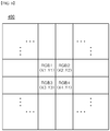
- FIG. 4 shows an example of a visible image of the circuit breaker.
- FIG. 5 shows an example of a thermal image of the circuit breaker.
- FIG. 6 shows color data detected at arbitrary coordinates of the visible image.
- FIG. 7 shows a color space for RGB data.
- FIG. 8 shows emissivity at arbitrary coordinates of the thermal image.
- FIG. 9 shows a thermal image corrected based on emissivity.
- a circuit breaker opening/closing assistance device 100 may include a material identification unit 110, an image correction unit 120, a diagnosis unit 130, and a controller 140.
- the circuit breaker opening/closing assistance device 100 shown in FIG. 1 is exemplary. The components thereof are not limited to the embodiment shown in FIG. 1 . Some components may be added, changed, or deleted as necessary.
- Each of the components constituting the circuit breaker opening/closing assistance device 100 may include a processor and a memory and may perform each function as described below via operation of the processor using the memory. Alternatively, the components may perform the functions as described below using one main processor.
- the circuit breaker opening/closing assistance device 100 may be connected to the circuit breaker 10 disposed between and connected to a power system 200 and a load 300.
- the circuit breaker 10 is briefly illustrated. However, as described above, the circuit breaker 10 may be embodied as various types thereof for selectively opening and closing a circuit between the power system 200 and the load 300.
- the circuit breaker 10 may be an air circuit breaker (ACB) that performs cut-off operation via an arc extinguishing scheme using air as an insulating material.
- ACB air circuit breaker
- FIG. 3 is an example of the circuit breaker 10, and is a view showing the air circuit breaker.
- the circuit breaker 10 may have an internal circuit (not shown) for performing a cut-off operation, which is mounted in a casing equipped with an external interface.
- the user may supply power to the circuit breaker 10 or stop the power supply thereto via the external interface and may monitor an operation status of the circuit breaker 10 via the external interface and may control magnitude of current to be blocked via the external interface.
- the material identification unit 110 may acquire a visible image 400 of the circuit breaker 10 using a light source.
- the material identification unit 110 may receive the visible image 400 from a camera (not shown) installed inside or outside the circuit breaker opening/closing assistance device 100 via data communication with the camera.
- the camera may sense light reflected from the circuit breaker 10.
- the camera may be a digital camera capable of data communication.
- the material identification unit 110 may control on/off, intensity of illumination, and irradiation angle of the light source.
- the camera may detect light as generated by the light source and reflected from the circuit breaker 10 to generate the visible image 400.
- the camera may be installed outside the circuit breaker 10 to detect light reflected from an outside of the circuit breaker 10 to generate the visible image 400.
- the camera may be installed inside the circuit breaker 10 to detect visible light from a component inside the circuit breaker 10 to generate the visible image 400.
- a position of the camera is not limited thereto.
- the camera may be installed at any position where the camera may detect the light as generated by the light source and reflected from the circuit breaker 10.
- the camera may generate the visible image 400 of a bus bar 11 and a portion adjacent to a heat dissipating plate 12 in the circuit breaker 10.
- the generated visible image 400 may be provided to the material identification unit 110.
- the material identification unit 110 may identify a material imaged on the visible image 400.
- Materials constituting the circuit breaker 10 may have different colors. Accordingly, the materials imaged on the visible image 400 may have different colors based on types of the materials.
- the material identification unit 110 may identify a type of a material imaged on the visible image 400 based on a color rendered on the visible image 400.
- the material identification unit 110 may identify a type of a material imaged at each coordinate of the visible image 400 based on color data detected at each coordinate of the visible image 400.
- the material identification unit 110 may detect a coordinate of any measurement point in the visible image 400, and may extract color data corresponding to the detected coordinate.
- the visible image 400 may be divided into a matrix having coordinates.
- the material identification unit 110 may define coordinates corresponding to first to fourth measurement points as (X1, Y1), (X2, Y2), (X3, Y3), and (X4, Y4).
- the material identification unit 110 may extract color data rendered at the detected coordinates.
- the color data may include RGB (Red, Green, Blue) data, HSV (Hue Saturation Value) data, CMY (Cyan, Magenta, Yellow) data, YUV data, and CMYK data.
- RGB Red, Green, Blue
- HSV Human Saturation Value
- CMY Cyan, Magenta, Yellow
- YUV data YUV data
- CMYK data CMYK data.
- the color data is assumed to be RGB data.
- the material identification unit 110 may extract R (Red) component, G (Green) component, and B (Blue) component of a color rendered at the coordinate of the measurement point and collect the extracted components to generate the color data.
- the material identification unit 110 may collect R component, G component, and B component of a color expressed at the (X1, Y1) coordinate and may determine color data at the first measurement point as RGB 1.
- the material identification unit 110 may collect R component, G component, and B component of each of colors rendered at the coordinates (X2, Y2), (X3, Y3), and (X4, Y4) and may determine color data at the second to fourth measurement points as RGB 2, RGB 3 and RGB 4, respectively.
- FIG. 4 shows a manner in which color data only at the four coordinates are detected.
- the material identification unit 110 may detect color data at an arbitrary coordinate in the visible image 400.
- the material identification unit 110 may identify a type of a material imaged at each coordinate based on color data at each coordinate.
- the material identification unit 110 may identify the type of the material imaged at each coordinate with reference to reference color data stored in a memory.
- the reference color data may include information on a type of a material corresponding to detected color data.
- the reference color data may be stored in a memory in a form of a color table corresponding to an arbitrary material or may be stored in a memory in a form of a color space corresponding to an arbitrary material.
- the memory stores therein a RGB color space expressed in a three-dimensional space based on magnitudes of R component, G component, and B component, and information about a material corresponding to an arbitrary position of the RGB color space.
- the material identification unit 110 may identify, as C1 to C4, positions corresponding to color data RGB 1, RGB 2, RGB 3, and RGB 4 respectively detected at the coordinates (X1, Y1), (X2, Y2), (X3, Y3), and (X4, Y4) of the first to fourth measurement points as described above in the RGB color space, respectively.
- materials corresponding to positions of the RGB color space, respectively as shown in [Table 1] below may be stored in a memory of the material identification unit 110.
- [Table 1] [Positions] [Materials] C1 M1 C2 M2 C3 M3 C4 M4
- the material identification unit 110 may identify a material imaged at the coordinate (X1, Y1) of the first measurement point as M1, a material imaged at the coordinate (X2, Y2) of the second measurement point as M2, a material imaged at the coordinates (X3, Y3) of the third measurement point as M3, and a material imaged at the coordinates (X4, Y4) of the fourth measurement point as M4.
- the image correction unit 120 may acquire a thermal image 500 of the circuit breaker 10.
- the image correction unit 120 may receive the thermal image 500 from a thermal imaging camera (not shown) installed inside or outside the circuit breaker opening/closing assistance device 100 via data communication with the thermal imaging camera.
- the thermal imaging camera may include any camera that detects heat generated by the circuit breaker 10.
- the thermal imaging camera may include an infrared camera.
- the thermal imaging camera may be installed outside the circuit breaker 10 to detect the heat generated from the outside of the circuit breaker 10, or may be installed inside the circuit breaker 10 to detect the heat generated by a component inside the circuit breaker 10.
- the thermal imaging camera may generate the thermal image 500 using heat radiated from the circuit breaker 10. More specifically, the thermal imaging camera may express the circuit breaker 10 in different colors based on different intensities of heat radiated from different parts of the circuit breaker 10 to generate the thermal image 500.
- the circuit breaker 10 may be expressed in different colors based on a reference temperature range 520 of the thermal image 500.
- the reference temperature range 520 may include temperature information based on a color rendered on the thermal image 500.
- an imaging range of the thermal imaging camera may be included in an imaging range of the camera as aforementioned. That is, the imaging range of the camera may include an entirety of the imaging range of the thermal imaging camera.
- any part of the circuit breaker 10 expressed on the thermal image 500 may be included in the visible image 400 as described above.
- a specific imaging region 510 expressed on the thermal image 500 in FIG. 5 may be included in the visible image 400 in FIG. 4 (410 in FIG. 4 ).
- the bus bar 11 is a conductor that supplies a large amount of current to the load 300.
- a temperature of the bus bar 11 may increase significantly as magnitude of current flowing via the load 300 increases.
- the heat dissipating plate 12 adjacent to the bus bar 11 is a conductor having a large surface area, and may absorb the heat generated from the bus bar 11 to lower the temperature of the bus bar 11.
- the temperature of the bus bar 11 may always be higher than the temperature of the heat dissipating plate 12.
- the temperature of the heat dissipating plate 12 may be expressed to be higher than the temperature of the bus bar 11 in a specific imaging region 510 of the thermal image 500 as shown in FIG. 5 .
- the image correction unit 120 may correct the thermal image 500 based on the emissivity of the material as identified by the material identification unit 110.
- the thermal image 500 may be corrected so that the temperature of the material in the thermal image 500 is detected to be lower.
- the image correction unit 120 may correct the thermal image 500 so that the temperature of the material in the thermal image 500 is detected to be higher.
- the image correction unit 120 may correct the thermal image 500 in a corresponding manner to the coordinates of the visible image 400, based on the identified emissivity of the material.
- the imaging range of the thermal image 500 may be included in the imaging range of the visible image 400.
- a coordinate of the visible image 400 corresponding to a point on the circuit breaker 10 may be the same as that of the thermal image 500.
- the coordinates (X1, Y1), (X2, Y2), (X3, Y3), and (X4, Y4) of the first to fourth measurement points in the visible image 400 shown in FIG. 6 may be the same as the coordinates of the first to fourth measurement points in the thermal image 500 shown in FIG. 8 .
- the visible image 400 and thermal image 500 may share the same coordinate system.
- the coordinate of one point on the circuit breaker 10 in the visible image 400 may be the same as the coordinate of one point on the circuit breaker 10 in the thermal image 500.
- the image correction unit 120 may determine the emissivity of the material identified at each coordinate of the visible image 400 with reference to the memory, and may correct color data at each coordinate of the thermal image 500 based on the determined emissivity.
- Each material and each emissivity of each material may be stored in the memory of the image correction unit 120 in A form of a look up table (LUT).
- LUT look up table
- each emissivity corresponding to each material may be previously stored in the memory as shown in [Table 2] below.
- [Table 2] [Material] [Emissivity] M1 e1 M2 e2 M3 e3 M4 e4
- the image correction unit 120 may determine the emissivity of the material identified at each coordinate of the visible image 400 with reference to the memory.
- the image correction unit 120 may determine emissivity of a material (M1) identified at the coordinate (X1, Y1) of the first measurement point as e1, emissivity of a material (M2) identified at the coordinate (X2, Y2) of the second measurement point as e2, emissivity of a material (M3) identified at the coordinate (X3, Y3) of the third measurement point as e3, and emissivity of a material (M4) identified at the coordinate (X4, Y4) of the fourth measurement point as e4.
- the material identification unit 110 may detect color change of the visible image 400 based on movement of the light source.
- the image correction unit 120 may determine the emissivity of the material based on the material imaged on the visible image 400 and the color change of the visible image 400.
- the material identification unit 110 may control the light source. More specifically, the material identification unit 110 may control an angle of the light source or a position of the light source.
- the camera may generate the visible image 400 based on the movement of the light source.
- the camera may provide the visible image 400 generated within a continuous time for which the light source moves to the material identification unit 110.
- the material identification unit 110 may identify the material imaged at each coordinate of the visible image 400 based on the visible image 400 initially provided from the camera.
- the material identification unit 110 may receive a plurality of visible images 400 based on the movement of the light source from the camera, and may detect color change based on the movement of the light source at an arbitrary coordinate of the visible image 400.
- the emissivity of the material may vary depending on a surface state of the material. More specifically, when the surface of the material is smoother, the emissivity thereof may be relatively higher. To the contrary, when the surface of the material is rougher, the emissivity thereof may be relatively lower.
- the emissivity of the material when the surface of the material is smooth, reflectance of light generated from the light source from the material is relatively high. Thus, the emissivity of the material may be relatively higher. To the contrary, when the surface of the material is rough, the reflectance of light generated from the light source from the material is relatively low due to diffuse reflection. Thus, the emissivity thereof may be relatively lower.
- the image correction unit 120 may determine the emissivity of the material based on the color change detected by the material identification unit 110.
- the image correction unit 120 may determine an emissivity range of the material imaged on the visible image 400 with reference to the memory, and may determine the emissivity included in the emissivity range based on the color change.
- emissivity of the material (M5) imaged at an arbitrary coordinate of the visible image 400 may be prestored in the memory as shown in [Table 3] below.
- [Table 3] [Material] [Emissivity] M5 e5 to e6
- the image correction unit 120 may determine the emissivity range of the material M5 as a range from e5 to e6 with referring to the memory.
- the memory may pre-store maximum and minimum color changes of each of the materials therein.
- the image correction unit 120 may determine the emissivity of the material M5 based on the color change of the material M5 as determined in the range between the maximum color change and the minimum color change.
- the image correction unit 120 may detect the color change of the material M5, and may determine the emissivity of the material M5 based the detected color change and a ratio between the maximum color change and the minimum color change of the material M5.
- the color change of the material M5 as identified based on the visible image 400 may be R1+0.8 ⁇ (R2-R1).
- the image correction unit 120 may determine the emissivity of the material M5 as e5+0.8 ⁇ (e6-e5) in a proportional manner to the color change of the material M5 determined in the range between maximum color change and the minimum color change.
- the emissivity of the material imaged on the visible image may be determined based on the color change of the visible image.
- the surface state of the material may be considered.
- the image correction unit 120 may correct color data at each coordinate of the thermal image 500.
- the emissivity of the material imaged at each coordinate may be determined at each coordinate of the thermal image 500.
- the image correction unit 120 may correct the color data at each coordinate of the thermal image 500 based on the determined emissivity at each coordinate.
- the image correction unit 120 may provide an emissivity control signal to the thermal imaging camera, so that the thermal imaging camera changes the default emissivity set at each coordinate of the thermal image 500 to the emissivity determined based on each material.
- the image correction unit 120 may not communicate with the thermal imaging camera and may change the color data at each coordinate of the thermal image 500 based on the determined emissivity of each material.
- a method of correcting the thermal image 500 based on the emissivity may be performed based on various schemes used in the art.
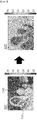
- the thermal image 500 before the correction may include a person 530 and a concrete 540.
- emissivity of the person 530 may be determined, for example, as 0.98
- the emissivity of the concrete 540 may be determined, for example, 0.8.
- the image correction unit 120 may correct color data corresponding to each coordinate of the thermal image 500 based on the determined emissivity, thereby to generate a corrected thermal image 500'.
- the thermal image of the circuit breaker may be corrected based on the emissivity of the material constituting the circuit breaker, such that the accuracy of temperature measurement based on the thermal image may be improved.
- the diagnosis unit 130 may identify a normal operation state of the circuit breaker 10 based on a temperature value (hereinafter, detected temperature value) detected on the corrected thermal image 500', and may compare the identified normal operation state with a current operation state of the circuit breaker 10, and may diagnose absence or presence of failure of the circuit breaker 10 based on the comparison result.
- a temperature value hereinafter, detected temperature value
- the normal operation state may mean a normal closed/opened state of the circuit breaker 10 within a temperature condition detected on the corrected thermal image 500'.
- the temperature of the circuit breaker 10 may increase as current supplied to the load 300 increases within a temperature range in which the circuit breaker 10 does not block the current supplied to the load 300.
- a temperature value detected at a moment when the current supplied to the load 300 becomes overcurrent will be defined as a limit temperature.
- a state in which the circuit breaker 10 allows supply of power from the power system 200 to the load 300 is defined as a closed state of the circuit breaker.
- a state in which the circuit breaker 10 disallows supply of power from the power system 200 to the load 300 is defined as an opened state of thereof.
- the circuit breaker 10 when the circuit breaker 10 is operating normally, and when the detected temperature value is below the limit temperature, the circuit breaker 10 may be controlled to be brought into the closed state. Conversely, when the detected temperature value is above or equal to the limit temperature, the circuit breaker 10 may be controlled to be brought into the opened state.
- the normal operation state of the circuit breaker 10 based on the detected temperature value may be pre-stored in the memory. More specifically, the normal operation state of the circuit breaker 10 based on the temperature value detected at any measurement point of the circuit breaker 10 may be pre-stored in the memory.
- the diagnosis unit 130 may identify the normal operation state of the breaker based on the detected temperature value with reference to the memory.
- the limit temperature at any measurement point of the circuit breaker 10 when the overcurrent flows in the load 300 may be pre-stored in the memory.
- the diagnosis unit 130 may identify the normal operation state of the circuit breaker 10 as the closed state when the detected temperature value is lower than the limit temperature. To the contrary, the diagnosis unit 130 may identify the normal operation state of the circuit breaker 10 as the opened state when the detected temperature value is above or equal to the limit temperature.
- the diagnosis unit 130 may determine whether the overcurrent has occurred in the load 300, based on the detected temperature value at any measurement point of the circuit breaker 10 and thus may identify a normal closed/opened state of the circuit breaker 10 based on whether the overcurrent has occurred in the load 300.
- the above-described detected temperature value may be a temperature value detected at an arbitrary point among temperature values detected on the thermal image 500'.
- the detected temperature value may be a maximum temperature value among temperature values detected on the thermal image 500'.
- the diagnosis unit 130 may identify the maximum temperature value among the temperature values detected on the thermal image 500', and may identify the normal operation state of the circuit breaker 10 based on the identified maximum temperature value.
- the diagnosis unit 130 may compare the identified normal operation state with a current operation state of the circuit breaker 10 and may diagnose the absence or presence of failure of the circuit breaker 10, based on the comparison result.
- the current operation state of the circuit breaker 10 may mean a current closed/opened state of the circuit breaker 10.
- the diagnosis unit 130 may receive information on an operating state of the circuit breaker 10 from the circuit breaker 10, and may identify the current operation state of the circuit breaker 10, based on the received operation state information.
- the diagnosis unit 130 may diagnose the absence or presence of failure of the circuit breaker 10 based on whether the normal operation state matches the current operation state of the circuit breaker 10.
- each of the normal operation state and the current operation state may be the opened state or the closed state.
- the diagnosis unit 130 may determine whether the normal closed/opened state of the circuit breaker 10 as identified based on the detected temperature value is identical with the current closed/opened state of the circuit breaker 10, and may diagnose the absence or presence of failure of the circuit breaker 10, based on the determination result.
- the diagnosis unit 130 may determine that overcurrent does not flow in the load 300 and thus may determine the normal operation state of the circuit breaker 10 as the closed state.
- the current closed/opened state of the circuit breaker 10 operating normally may be a closed state
- the current closed/opened state of the circuit breaker 10 in which failure occurs may be an opened state.
- the diagnosis unit 130 may determine that overcurrent flows in the load 300, and thus may determine the normal operation state of the circuit breaker 10 as an opened state.
- the current closed/opened state of the circuit breaker 10 operating normally may be an opened state
- the current closed/opened state of the circuit breaker 10 where failure has occurred may be a closed state.
- the diagnosis unit 130 may diagnose a state of the circuit breaker 10 as a normal state when the normal operation state and the current operation state are identical with each other.
- the diagnosis unit 130 may diagnose a state of the circuit breaker 10 as a failure state.
- comparing the normal closed/opened state of the circuit breaker as identified based on the thermal image of the circuit breaker with the current closed/opened state thereof may allow grasping the absence or presence of failure of the circuit breaker.
- the controller 140 may receive information on the absence or presence of failure of the circuit breaker 10 from the diagnosis unit 130 as described above, and may create a control signal based on the absence or presence of failure of the circuit breaker 10 and may transmit the control signal to the circuit breaker 10.
- the control signal may be a signal that controls the opening and closing of the circuit breaker 10.
- the controller 140 may generate the control signal when the circuit breaker 10 is diagnosed as a failure state, and may provide the generated control signal to the circuit breaker 10. In other words, the controller 140 may not generate the control signal when the circuit breaker 10 is diagnosed as a normal state. Thus, the control signal may be generated only when the circuit breaker 10 is diagnosed as a failure state.
- the circuit breaker 10 may perform an opening/closing operation based on the control signal.
- the control signal may include an opening control signal and a closing control signal.
- the opening control signal may be a signal that controls the current closed/opened state of the circuit breaker 10 to the opened state.
- the closing control signal may be a signal that controls the current closed/opened state of the circuit breaker 10 to the closed state.
- the controller 140 may provide the opening control signal to the circuit breaker 10 when the normal operation state of the circuit breaker 10 is an opened state and the current operation state of the circuit breaker 10 is an closed state.
- the controller 140 may provide the closing control signal to the circuit breaker 10.
- the opening/closing operation of the circuit breaker may be assisted based on the temperature detected on the thermal image of the circuit breaker, thereby to prevent overcurrent occurrence and power supply interruption due to malfunction of the circuit breaker.
- the control signal when a signal for controlling the opening and closing is not properly applied to the relay in the circuit breaker (relay malfunction), the control signal may be created and may be provided to the circuit breaker, thereby to allow the circuit breaker to work normally.
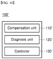
- FIG. 10 is a diagram showing a circuit breaker opening/closing assistance device according to another embodiment of the present disclosure.
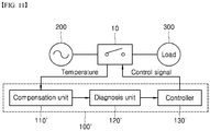
- FIG. 11 is a diagram illustrating a manner in which the circuit breaker opening/closing assistance device according to another embodiment of the present disclosure controls the circuit breaker connected to and disposed between a power system and a load
- FIG. 12 is a diagram showing a thermal image obtained by imaging a plurality of measurement points set in the circuit breaker.
- FIG. 13 is a view illustrating a manner in which a temperature reference value of the thermal image shown in FIG. 12 is adjusted based on a compensation value.
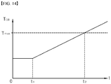
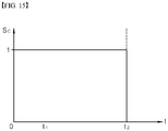
- FIG. 14 and FIG. 15 are graphs respectively showing a temperature value of the thermal image and a control signal generated based on the temperature value.
- a circuit breaker opening/closing assistance device 100' may include a compensation unit 110', a diagnosis unit 120', and a controller 130'.
- the circuit breaker opening/closing assistance device 100' shown in FIG. 10 is an example.
- the components therein are not limited to the embodiment shown in FIG. 10 . Some components may be added, changed, or deleted as necessary.
- Each of the components constituting the circuit breaker opening/closing assistance device 110' may include a processor and a memory and may perform each function as described below via operation of the processor using the memory. Alternatively, the components may perform the functions as described below using one main processor.
- the circuit breaker opening/closing assistance device 100' may be connected to the circuit breaker 10 disposed between a power system 200 and a load 300.
- the circuit breaker 10 has been described with reference to FIG. 1 to FIG. 9 , and, thus, detailed descriptions thereof will be omitted herein.
- the compensation unit 110' may detect a first temperature based on the thermal image 500 of the circuit breaker 10.
- the compensation unit 110' may receive the thermal image 500 from a thermal imaging camera (not shown) installed inside or outside the circuit breaker opening/closing assistance device 100' via data communication with the thermal imaging camera.
- the thermal imaging camera may include any camera that detects the heat generated from the circuit breaker 10.
- the thermal imaging camera may include an infrared camera.
- the thermal imaging camera may be installed outside the circuit breaker 10 to detect the heat generated from an outer face of the circuit breaker 10, or may be installed inside the circuit breaker 10 to detect the heat generated from a circuit in the circuit breaker 10.
- a position of the thermal imaging camera is not limited thereto and may vary based on a position of a measurement point to be described later.
- the thermal imaging camera may generate the thermal image 500 using heat radiated from the circuit breaker 10. More specifically, the thermal imaging camera may express the circuit breaker 10 in different colors based on intensities of heats radiated from parts of the circuit breaker 10 to generate the thermal image 500.
- the circuit breaker 10 expressed on the thermal image 500 may be expressed in different colors based on a reference temperature range of the thermal image 500.
- the reference temperature range may be set as a range between a maximum temperature reference value 550 and a minimum temperature reference value 560.
- the position When a temperature at one position of the circuit breaker 10 is the maximum temperature reference value 550, the position may be expressed in white on the thermal image 500. When a temperature at another position of the circuit breaker 10 is the minimum temperature reference value 560, the position may be expressed in black on the thermal image 500.
- the correction unit may receive the thermal image 500 from the thermal imaging camera, and may detect a first temperature of the circuit breaker 10 based on a color rendered on the thermal image 500.
- the correction unit may refer to a color of each part of the circuit breaker 10 expressed on the thermal image 500 and a color defined in the reference temperature range of the thermal image 500 to detect the first temperature of each part of the circuit breaker 10.
- At least one measurement point may be preset on the circuit breaker 10.
- the measurement point may mean a position at which a temperature is measured.
- the measurement point may include a specific position included in an internal circuit of the circuit breaker 10, a contact position of the circuit breaker 10, a position of the bus bar, and an arbitrary position on an outer case of the circuit breaker 10.
- the compensation unit 110' may detect a coordinate of the measurement point on the thermal image 500, and may detect the first temperature corresponding to the detected coordinate.
- Each point on the thermal image 500 may have a coordinate defined by a horizontal axis X and a vertical axis Y on the thermal image 500.
- a plurality of measurement points for example, first to fourth measurement points A1 to A4 may be preset on the circuit breaker 10.
- the compensation unit 110' may detect a coordinate of a measurement point on the circuit breaker 10 on the thermal image 500.
- the compensation unit 110' may detect the coordinates of the first to fourth measurement points A1 to A4 as (U1, V1), (U2, V2), (U3, V3), and (U4, V4).
- the compensation unit 110' may detect the first temperature corresponding to the detected coordinate at each measurement point.
- the compensation unit 110' may compare a color of the (U1, V1) coordinate with the reference temperature range to determine a temperature corresponding to the (U1, V1) coordinate, and may detect the determined temperature as the first temperature at the first measurement point (A1). In this way, the compensation unit 110' may compare colors of the (U2, V2), (U3, V3), and (U4, V4) coordinates with the reference temperature range to determine temperatures corresponding to the coordinates, and may detect each of the determined temperatures as the first temperature of each of the second to fourth measurement points A2 to A4.
- the compensation unit 110' may compensate for a temperature value of the thermal image 500 using the first temperature detected in the above manner and a second temperature provided from a plurality of temperature sensors.
- the plurality of temperature sensors may be installed on the circuit breaker 10.
- Each temperature sensor may be an analog temperature sensor, such as a thermistor or may be a digital temperature sensor.
- the plurality of temperature sensors may be installed at any positions on the circuit breaker 10 to measure the second temperature as a temperature of each of the installation positions.
- the plurality of temperature sensors may be installed in a specific position included in an internal circuit of the circuit breaker 10, a contact position of the circuit breaker 10, a position of the bus bar, and a position on an outer casing of the circuit breaker 10.
- the second temperature at each position may be measured by each temperature sensor.
- the plurality of temperature sensors may be respectively provided on at least one measurement point as described above to measure the second temperature of each measurement point.
- the plurality of temperature sensors may be installed at the first to fourth measurement points A1 to A4 shown in FIG. 12 , respectively.
- the plurality of temperature sensors may measure the second temperatures at the first to fourth measurement points A1 to A4, respectively.
- the compensation unit 110' may receive the second temperature at each measurement point from each of the plurality of temperature sensors, and may compensate for the temperature value of the thermal image 500 using the first temperature and second temperature as above-described.
- Each temperature sensor may be installed at each measurement point to directly measure the temperature of the measurement point.
- the thermal imaging camera may indirectly measure the temperature of each measurement point using infrared rays, etc.
- the second temperature measured by the temperature sensor may be higher than the first temperature detected based on the thermal image 500.
- the compensation unit 110' may compensate for the temperature value of the thermal image 500 such that the first temperature follows the second temperature.
- the compensation unit 110' may determine a compensation value using the first temperature and the second temperature at each of the plurality of measurement points set on the circuit breaker 10, and may compensate for the temperature value of the thermal image 500 using the determined compensation value.
- the compensation value may be determined as an average value of difference values between the first temperatures and the second temperatures.
- the compensation unit 110' may identify the first temperatures of the first to fourth measurement points A1 to A4 as T1, T2, T3, and T4, respectively, based on the thermal image 500. Further, the second temperatures of the first to fourth measurement points A1 to A4 provided from the plurality of temperature sensors may be T1', T2', T3', and T4', respectively.
- the compensation unit 110' may determine an average value of values obtained by subtracting the first temperatures from the second temperatures at the first to fourth measurement points A1 to A4.
- the compensation unit 110' may add the compensation value to the temperature reference value of the thermal image 500 to compensate for the temperature value of the thermal image 500.
- the compensation unit 110' may add the compensation value to each of the maximum temperature reference value 550 and the minimum temperature reference value 560 of the thermal image 500 to change the reference temperature range of the thermal image 500.
- the maximum temperature reference value 550 and minimum temperature reference value 560 before the compensation by the compensation unit 110' may be 66 degrees C and 58.7 degrees C, respectively. Accordingly, the reference temperature range may be set to a range from 58.7 to 66 degrees C.
- the compensation unit 110' may add the compensation value (Q) to each of the existing maximum temperature reference value 550 and minimum temperature reference value 560, so that the maximum temperature reference value 550 may be changed to 66+Q degrees C and the minimum temperature reference value 560 may be changed to 58.7+Q degrees C. Accordingly, the reference temperature range may be set to a range from 58.7+Q to 66+Q degrees C.
- the compensated temperature value of the thermal image 500 may be detected to be higher by Q degrees than the temperature value thereof before the compensation operation.
- the device may compensate for the temperature value detected on the thermal image of the circuit breaker to improve the accuracy of temperature measurement based on the thermal image.
- the diagnosis unit 120' may identify a normal operation state of the circuit breaker 10 based on a temperature value (hereinafter, detected temperature value: T CB ) detected on the compensated thermal image 500.
- the normal operation state may mean a normal closed/opened state of the circuit breaker 10 within the temperature condition detected on the compensated thermal image 500.
- a temperature value T CB detected at a moment when the current supplied to the load 300 becomes overcurrent is defined as a limit temperature T max .
- a state in which the circuit breaker 10 allows supply of power from the power system 200 to the load 300 is defined as a closed state thereof.
- a state in which the circuit breaker 10 disallows supply of power from the power system 200 to the load 300 is defined as an opened state.
- the normal operation state of the circuit breaker 10 based on the detected temperature value T CB may be pre-stored in the memory. More specifically, the normal operation state of the circuit breaker 10 based on the temperature value detected at an arbitrary measurement point may be pre-stored in the memory.
- the diagnosis unit 120' may identify the normal operation state of the circuit breaker 10 based on the detected temperature value T CB with reference to the memory.
- the limit temperature T max at any measurement point when overcurrent flows in the load 300 may be pre-stored in the memory.
- the diagnosis unit 120' may compare the detected temperature value T CB with the limit temperature T max to identify the normal operation state of the circuit breaker 10.
- the detected temperature value T CB may gradually increase since a time point t 1 when the load 300 starts to operate and then may exceed the limit temperature T max at a specific time point t 2 .
- the diagnosis unit 120' may identify the normal operation state of the circuit breaker 10 as a closed state for a period from 0 to t 2 and may identify the normal operation state of the circuit breaker 10 as an opened state for a period after t 2 .
- the diagnosis unit 120' may determine whether overcurrent has occurred in the load 300, based on the detected temperature value T CB at any measurement point of the circuit breaker 10 and may identify the normal closed/opened state of the circuit breaker 10 based on whether the overcurrent has occurred.
- the diagnosis unit 120' may identify the normal operation state based on change in the detected temperature value T CB .
- the change in the detected temperature value T CB may mean an amount by which the detected temperature value T CB at any measurement point of the circuit breaker 10 changes for a unit time duration.
- the detected temperature value T CB may also increase sharply.
- the diagnosis unit 120' may determine that overcurrent flows in the load 300 even when the detected temperature value T CB is lower than the limit temperature T max .
- a maximum change in the detected temperature value T CB at any measurement point may be pre-stored in the memory.
- the diagnosis unit 120' may compare the temperature change in the detected temperature value T CB and the maximum change with each other with reference to the memory and may identify a normal operation state of the circuit breaker based on the comparison result.
- the diagnosis unit 120' may identify the normal operation state of the circuit breaker 10 as a closed state. To the contrary, when the temperature change in the detected temperature value TCB exceeds the maximum change, the normal operation state of the circuit breaker 10 may be identified as an opened state.
- the diagnosis unit 120' may compare the identified normal operation state with the current operation state of the circuit breaker 10 and diagnose the absence or presence of failure of the circuit breaker 10 based on the comparison result.
- the current operation state of the circuit breaker 10 may mean the current open/closed state of the circuit breaker 10.
- the diagnosis unit 120' may receive information on the operating state of the circuit breaker 10 from the circuit breaker 10, and may identify the current operation state of the circuit breaker 10 based on the received operation state information.
- the diagnosis unit 120' may diagnose the absence or presence of failure of the circuit breaker 10 based on whether the normal operation state matches the current operation state of the circuit breaker 10.
- each of the normal operation state and the current operation state may be an opened state or a closed state.
- the diagnosis unit 120' may determine whether the normal closed/opened state of the circuit breaker 10 as identified based on the detected temperature value T CB and the current closed/opened state of the circuit breaker 10 are identical with each other and may diagnose absence or presence of failure of the breaker 10 based on the comparison result.
- the diagnosis unit 120' may determine that overcurrent does not flow in the load 300 and may determine the normal operation state of the circuit breaker 10 as a closed state.
- the current closed/opened state of the circuit breaker 10 operating normally may be a closed state
- the current closed/opened state of the circuit breaker 10 in which failure occurs may be an opened state.
- the diagnosis unit 120' may determine that overcurrent flows in the load 300 and may determine the normal operation state of the circuit breaker 10 as an opened state.
- the current closed/opened state of the circuit breaker 10 operating normally may be an opened state, but the current closed/opened state of the circuit breaker 10 where failure has occurred may be a closed state.
- the diagnosis unit 120' may diagnose a state of the circuit breaker 10 as a normal state when the normal operation state and the current operation state are identical with each other.
- the diagnosis unit 120' may diagnose a state of the circuit breaker 10 as a failure state.
- the aforementioned detected temperature value T CB may be a temperature value detected at any point among temperature values detected on the thermal image 500.
- the detected temperature value T CB may be a maximum temperature value among temperature values detected on the thermal image 500.
- the diagnosis unit 120' may identify a maximum temperature value among the temperature values detected on the thermal image 500, and may identify the normal operation state of the circuit breaker 10 based on the identified maximum temperature value.
- the points on the thermal image 500 may have different temperatures, and, accordingly, may be expressed in different colors.
- the diagnosis unit 120' may identify a coordinate of a point having the maximum temperature on the thermal image 500, that is, a point expressed in a white color and may identify a maximum temperature value corresponding to the identified coordinate.
- the diagnosis unit 120' may compare the identified maximum temperature value with the limit temperature T max and identify the normal operation state of the circuit breaker 10 based on the comparison result.
- the diagnosis unit 120' may compare the identified normal operation state with the current operation state of the circuit breaker 10 and may diagnose the absence or presence of failure of the circuit breaker 10 based on the comparison result.
- a method of diagnosing the absence or presence of failure of the circuit breaker 10 is the same as described above, and thus detailed descriptions thereof will be omitted herein.
- the diagnosis unit 120' may diagnose a state of the circuit breaker 10 as an opened failure state when the normal operation state is an opened state and the current operation state is a closed state. Conversely, when the normal operation state is a closed state and the current operation state is an opened state, the diagnosis unit 120' may diagnose a state of the circuit breaker 10 as a closed failure state.
- the opened failure state means a state in which the circuit breaker 10 should have been but has not been switched from a closed state to an opened state.
- the closed failure state may mean a state in which the circuit breaker 10 should have been but has not been switched from an opened state to a closed state
- the circuit breaker 10 should be controlled to be brought into the opened state.
- the diagnosis unit 120' may diagnose a state of the circuit breaker 10 as an opened failure state.
- the circuit breaker 10 should be controlled to be brought into a closed state.
- the diagnosis unit 120' may diagnose the state of the circuit breaker 10 as the closed failure state.
- the device may compare the normal closed/opened state of the circuit breaker identified based on the thermal image of the circuit breaker with the current closed/opened state thereof and may grasp the absence or presence of failure of the circuit breaker, based on the comparison result.
- the controller 130' may receive information on the absence or presence of failure of the circuit breaker 10 from the diagnosis unit 120' as described above, and may create a control signal Sc, based on the absence or presence of failure of the circuit breaker 10 and may provide the control signal Sc to the circuit breaker 10.
- the control signal Sc is a signal that controls the opening and closing of the circuit breaker 10, and may be a digital signal or an analog pulse signal.
- the controller 130' may generate the control signal Sc when the circuit breaker 10 is diagnosed as a failure state, and may provide the generated control signal Sc to the circuit breaker 10.
- the controller 130' when the circuit breaker 10 is diagnosed as a normal state, the controller 130' does not generate the control signal Sc.
- the control signal Sc may be generated only when the circuit breaker 10 is diagnosed as a failure state.
- the circuit breaker 10 may perform an opening/closing operation based on the control signal Sc.
- the control signal Sc may include an opening control signal and a closing control signal.
- the opening control signal may be a signal that controls the current closed/opened state of the circuit breaker 10 to the opened state.
- the closing control signal may be a signal that controls the current closed/opened state of the circuit breaker 10 to the closed state.
- the controller 130' may generate the opening control signal when a state of the circuit breaker 10 is diagnosed as the opened failure state.
- the closing control signal may be generated and provided to the circuit breaker 10.
- the diagnosis unit 120' may identify the normal operation state of the circuit breaker 10 as a closed state for a period from 0 to t 2 and may identify the normal operation state of the circuit breaker 10 as an opened state for a period after t 2 .
- the controller 130' may generate the closing control signal having a high pulse (magnitude 1). Further, when a state of the circuit breaker 10 is diagnosed as an opened failure state for a period after t 2 , the controller 130' may generate the opening control signal having a low pulse (magnitude 0).
- a state of the circuit breaker 10 may be controlled to the closed state based on the high pulse, and may be controlled to the opened state based on the low pulse.
- the device may assist the opening/closing operation of the circuit breaker based on the temperature detected on the thermal image of the circuit breaker, thereby to prevent overcurrent occurrence and power supply interruption due to malfunction of the circuit breaker.
Landscapes
- Physics & Mathematics (AREA)
- General Physics & Mathematics (AREA)
- Engineering & Computer Science (AREA)
- Theoretical Computer Science (AREA)
- Spectroscopy & Molecular Physics (AREA)
- Computer Vision & Pattern Recognition (AREA)
- Multimedia (AREA)
- Nonlinear Science (AREA)
- Quality & Reliability (AREA)
- Radiation Pyrometers (AREA)
Abstract
Description
- The present disclosure relates to a circuit breaker opening/closing assistance device that identifies a temperature of the circuit breaker, and assists opening/closing operations of the circuit breaker, based on the identified temperature.
- A circuit breaker (CB) is connected to and disposed between a power system supplying power and a load receiving the power from the power system. When overcurrent flows in the load, the CB detects the overcurrent and prevents the power supply to the load.
- The circuit breaker includes a relay that selectively opens and closes a circuit. The relay may include, for example, OCR (Over Current Relay) operating via a mechanical contact, and EOCR (Electronic Over Current Relay) operating in a semiconductor contactless manner.
- The circuit breaker may provide a control signal to an internal relay based on an amount of current flowing via the load to selectively open and close the circuit.
- In this connection, when the control signal is not provided to the relay in a specific control period or an incorrect control signal is provided to the relay, an closed/opened state of the relay is incorrect so that overcurrent flows in the load or power supplied to the load is cut off.
- Although current overcurrent and instantaneous power shutdown may adversely affect the load and other power systems connected to the load, the user may incorrectly trust an operating state of the circuit breaker and thus may incorrectly interpret states of the load and the power system.
- A purpose of the present disclosure is to provide a circuit breaker opening/closing assistance device that corrects a thermal image of the circuit breaker based on an emissivity of a material constituting the circuit breaker to improve accuracy of temperature measurement via the thermal image.
- Further, a purpose of the present disclosure to provide a circuit breaker opening/closing assistance device that determines an emissivity of a material imaged on a visible image based on a color change of the visible image to reflect a surface state of the material in correcting a thermal image.
- Further, a purpose of the present disclosure is to provide a circuit breaker opening/closing assistance device which compares a current closed/opened state of the circuit breaker with a normal closed/opened state of the circuit breaker as identified based on a thermal image of the circuit breaker to determine absence or presence of failure of the circuit breaker.
- Further, a purpose of the present disclosure is to provide a circuit breaker opening/closing assistance device that assists opening/closing operation of the circuit breaker based on a temperature detected based on a thermal image of the circuit breaker to prevent overcurrent occurrence and power supply interruption due to malfunction of the circuit breaker.
- Further, a purpose of the present disclosure is to provide a circuit breaker opening/closing assistance device that compensates for a temperature value detected based on a thermal image of the circuit breaker to improve accuracy of temperature measurement via the thermal image.
- Further, a purpose of the present disclosure is to provide a circuit breaker opening/closing assistance device which compares a current closed/opened state of the circuit breaker with a normal closed/opened state of the circuit breaker as identified based on a thermal image of the circuit breaker to determine absence or presence of failure of the circuit breaker.
- Further, a purpose of the present disclosure is to provide a circuit breaker opening/closing assistance device that assists opening/closing operation of the circuit breaker based on a temperature detected based on a thermal image of the circuit breaker to prevent overcurrent occurrence and power supply interruption due to malfunction of the circuit breaker.
- Purposes of the present disclosure are not limited to the above-mentioned purpose. Other purposes and advantages of the present disclosure as not mentioned above may be understood from following descriptions and more clearly understood from embodiments of the present disclosure. Further, it will be readily appreciated that the purposes and advantages of the present disclosure may be realized by features and combinations thereof as disclosed in the claims.
- In one aspect of the present disclosure, there is provided a device for assisting opening and closing of a circuit breaker connected to and disposed between a power system and a load, the device comprising: a material identification unit configured to acquire a visible image of the circuit breaker using a light source, and identify a material imaged on the acquired visible image; an image correction unit configured to acquire a thermal image of the circuit breaker, and correct the thermal image based on emissivity of the identified material; a diagnosis unit configured to: identify a normal operation state of the circuit breaker based on a temperature value detected on the corrected thermal image; and compare the identified normal operation state with a current operation state of the circuit breaker and diagnose absence or presence of failure of the circuit breaker based on the comparison result; and a controller configured to generate a control signal based on the absence or presence of the failure of the circuit breaker, and provide the generated control signal to the circuit breaker.
- In another aspect of the present disclosure, there is provided a device for assisting opening and closing of a circuit breaker having a plurality of temperature sensors disposed thereon, the device comprising: a compensation unit configured to compensate for a temperature value of a thermal image of the circuit breaker, based on a first temperature detected on the thermal image of the circuit breaker and a second temperature provided from each of the plurality of temperature sensors; a diagnosis unit configured to: identify a normal operation state of the circuit breaker based on a temperature value detected on the compensated thermal image; and compare the identified normal operation state with a current operation state of the circuit breaker and diagnose absence or presence of failure of the circuit breaker, based on the comparison result; and a controller configured to generate a control signal based on the absence or presence of the failure of the circuit breaker, and provide the generated control signal to the circuit breaker.
- According to the present disclosure as described above, correcting the thermal image of the circuit breaker based on the emissivity of the material constituting the circuit breaker may allow an effect of improving the accuracy of temperature measurement via the thermal image.
- Further, according to the present disclosure, determining the emissivity of the material imaged on the visible image based on the color change of the visible image may allow an effect of reflecting the surface state of the material in correcting the thermal image.
- Further, according to the present disclosure, comparing the normal closed/opened state as identified based on the thermal image of the circuit breaker with the current closed/opened state of the circuit breaker may allow an effect of grasping the absence or presence of the failure of the circuit breaker.
- Further, according to the present disclosure, assisting the opening/closing operation of the circuit breaker based on the temperature detected via the thermal image of the circuit breaker may allow an effect of preventing overcurrent occurrence and power supply interruption due to malfunction of the circuit breaker.
- Further, according to the present disclosure, compensating the temperature value detected via the thermal image of the circuit breaker may allow an effect of improving the accuracy of temperature measurement via the thermal image.
- Further, according to the present disclosure, comparing the normal closed/opened state as identified based on the thermal image of the circuit breaker with the current closed/opened state of the circuit breaker may allow an effect of identifying the absence or presence of failure of the circuit breaker.
- Further, according to the present disclosure, assisting the opening/closing operation of the circuit breaker based on the temperature detected via the thermal image of the circuit breaker may allow an effect of preventing overcurrent occurrence and power supply interruption due to malfunction of the circuit breaker.
-
-
FIG. 1 shows a circuit breaker opening/closing assistance device according to an embodiment of the present disclosure. -
FIG. 2 is a diagram illustrating a manner in which the circuit breaker opening/closing assistance device according to an embodiment of the present disclosure controls a circuit breaker connected to and disposed between a power system and a load. -
FIG. 3 is a diagram showing an example of the circuit breaker shown inFIG. 2 . -
FIG. 4 shows an example of a visible image of the circuit breaker. -
FIG. 5 shows an example of a thermal image of the circuit breaker. -
FIG. 6 shows color data detected at arbitrary coordinates of the visible image. -
FIG. 7 shows a color space for RGB data. -
FIG. 8 shows emissivity at arbitrary coordinates of the thermal image. -
FIG. 9 shows a thermal image corrected based on emissivity. -
FIG. 10 shows a circuit breaker opening/closing assistance device according to another embodiment of the present disclosure. -
FIG. 11 is a diagram illustrating a manner in which the circuit breaker opening/closing assistance device according to another embodiment of the present disclosure controls a circuit breaker connected to and disposed between a power system and a load. -
FIG. 12 is a diagram showing a thermal image obtained by imaging a plurality of measurement points set in the circuit breaker. -
FIG. 13 is a view illustrating a manner in which a temperature reference value of the thermal image shown inFIG. 12 is adjusted based on a compensation value. -
FIG. 14 andFIG. 15 are graphs respectively showing a temperature value of the thermal image and a control signal generated based on the temperature value. - The above-described purposes, features and advantages will be described in detail below with reference to the accompanying drawings. Accordingly, a person with ordinary skill in a technical field to which the present disclosure belongs may easily implement an technical idea of the present disclosure. In describing the present disclosure, when it is determined that a specific description of a known element related to the present disclosure may unnecessarily obscure a gist of the present disclosure, detailed descriptions thereof may be omitted. Hereinafter, preferred embodiments of the present disclosure will be described in detail with reference to the accompanying drawings. In the drawings, the same reference numerals are used to indicate the same or similar components.
- The present disclosure relates to a circuit breaker opening/closing assistance device that identifies a temperature of the circuit breaker, and assists opening/closing operation of the circuit breaker based on the identified temperature.
- More specifically, in one embodiment, the present disclosure relates to a device which corrects a thermal image of the circuit breaker based on a visible image of the circuit breaker, and assists opening/closing operation of the circuit breaker, based on a temperature identified via the corrected thermal image.
- Further, in another embodiment, the present disclosure relates to a circuit breaker opening/closing assistance device that identifies a temperature of the circuit breaker based on a thermal image of the circuit breaker where failure has occurred, and assists opening/closing operation of the circuit breaker based on the identified temperature.
- A circuit breaker (CB) is connected to and disposed between a power system supplying power and a load receiving the power from the power system. When overcurrent flows in the load, the CB detects the overcurrent and prevents the power supply to the load.
- The circuit breaker includes a relay that selectively opens and closes a circuit. The relay may include, for example, OCR (Over Current Relay) operating via a mechanical contact, and EOCR (Electronic Over Current Relay) operating in a semiconductor contactless manner.
- A circuit breaker opening/closing assistance device as described later may be connected to the circuit breaker as described above to diagnose absence or presence of failure of the circuit breaker, and to assist the circuit breaker in event of failure of the circuit breaker.
- Hereinafter, a circuit breaker opening/closing assistance device according to an embodiment of the present disclosure will be described in detail with reference to
FIG. 1 to FIG. 9 . -
FIG. 1 is a diagram showing a circuit breaker opening/closing assistance device according to an embodiment of the present disclosure.FIG. 2 is a diagram illustrating a manner in which the circuit breaker opening/closing assistance device according to an embodiment of the present disclosure controls a circuit breaker connected to and disposed between a power system and a load. -
FIG. 3 is a diagram showing an example of the circuit breaker shown inFIG. 2 . -
FIG. 4 shows an example of a visible image of the circuit breaker.FIG. 5 shows an example of a thermal image of the circuit breaker. -
FIG. 6 shows color data detected at arbitrary coordinates of the visible image.FIG. 7 shows a color space for RGB data.FIG. 8 shows emissivity at arbitrary coordinates of the thermal image. -
FIG. 9 shows a thermal image corrected based on emissivity. - Referring to
FIG. 1 , a circuit breaker opening/closing assistance device 100 according to an embodiment of the present disclosure may include amaterial identification unit 110, animage correction unit 120, adiagnosis unit 130, and acontroller 140. The circuit breaker opening/closing assistance device 100 shown inFIG. 1 is exemplary. The components thereof are not limited to the embodiment shown inFIG. 1 . Some components may be added, changed, or deleted as necessary. - Each of the components constituting the circuit breaker opening/
closing assistance device 100 may include a processor and a memory and may perform each function as described below via operation of the processor using the memory. Alternatively, the components may perform the functions as described below using one main processor. - Referring to
FIG. 2 , the circuit breaker opening/closing assistance device 100 may be connected to thecircuit breaker 10 disposed between and connected to apower system 200 and aload 300. InFIG. 2 , thecircuit breaker 10 is briefly illustrated. However, as described above, thecircuit breaker 10 may be embodied as various types thereof for selectively opening and closing a circuit between thepower system 200 and theload 300. - For example, the
circuit breaker 10 may be an air circuit breaker (ACB) that performs cut-off operation via an arc extinguishing scheme using air as an insulating material. -
FIG. 3 is an example of thecircuit breaker 10, and is a view showing the air circuit breaker. Referring toFIG. 3 , thecircuit breaker 10 may have an internal circuit (not shown) for performing a cut-off operation, which is mounted in a casing equipped with an external interface. - The user may supply power to the
circuit breaker 10 or stop the power supply thereto via the external interface and may monitor an operation status of thecircuit breaker 10 via the external interface and may control magnitude of current to be blocked via the external interface. - The
material identification unit 110 may acquire avisible image 400 of thecircuit breaker 10 using a light source. - The
material identification unit 110 may receive thevisible image 400 from a camera (not shown) installed inside or outside the circuit breaker opening/closing assistance device 100 via data communication with the camera. In this connection, the camera may sense light reflected from thecircuit breaker 10. The camera may be a digital camera capable of data communication. - The
material identification unit 110 may control on/off, intensity of illumination, and irradiation angle of the light source. In this connection, the camera may detect light as generated by the light source and reflected from thecircuit breaker 10 to generate thevisible image 400. - The camera may be installed outside the
circuit breaker 10 to detect light reflected from an outside of thecircuit breaker 10 to generate thevisible image 400. Alternatively, the camera may be installed inside thecircuit breaker 10 to detect visible light from a component inside thecircuit breaker 10 to generate thevisible image 400. A position of the camera is not limited thereto. The camera may be installed at any position where the camera may detect the light as generated by the light source and reflected from thecircuit breaker 10. - Referring to
FIG. 4 , in one example, the camera may generate thevisible image 400 of abus bar 11 and a portion adjacent to aheat dissipating plate 12 in thecircuit breaker 10. The generatedvisible image 400 may be provided to thematerial identification unit 110. - The
material identification unit 110 may identify a material imaged on thevisible image 400. - Materials constituting the
circuit breaker 10 may have different colors. Accordingly, the materials imaged on thevisible image 400 may have different colors based on types of the materials. - The
material identification unit 110 may identify a type of a material imaged on thevisible image 400 based on a color rendered on thevisible image 400. - More specifically, the
material identification unit 110 may identify a type of a material imaged at each coordinate of thevisible image 400 based on color data detected at each coordinate of thevisible image 400. - The
material identification unit 110 may detect a coordinate of any measurement point in thevisible image 400, and may extract color data corresponding to the detected coordinate. - Referring to
FIG. 6 , thevisible image 400 may be divided into a matrix having coordinates. In this connection, as shown inFIG. 6 , thematerial identification unit 110 may define coordinates corresponding to first to fourth measurement points as (X1, Y1), (X2, Y2), (X3, Y3), and (X4, Y4). - Subsequently, the
material identification unit 110 may extract color data rendered at the detected coordinates. In this connection, the color data may include RGB (Red, Green, Blue) data, HSV (Hue Saturation Value) data, CMY (Cyan, Magenta, Yellow) data, YUV data, and CMYK data. However, in following descriptions, the color data is assumed to be RGB data. - The
material identification unit 110 may extract R (Red) component, G (Green) component, and B (Blue) component of a color rendered at the coordinate of the measurement point and collect the extracted components to generate the color data. - For example, the
material identification unit 110 may collect R component, G component, and B component of a color expressed at the (X1, Y1) coordinate and may determine color data at the first measurement point asRGB 1. - In this way, the
material identification unit 110 may collect R component, G component, and B component of each of colors rendered at the coordinates (X2, Y2), (X3, Y3), and (X4, Y4) and may determine color data at the second to fourth measurement points as RGB 2, RGB 3 and RGB 4, respectively. - In one example,
FIG. 4 shows a manner in which color data only at the four coordinates are detected. However, this is for convenience of illustration. Thematerial identification unit 110 may detect color data at an arbitrary coordinate in thevisible image 400. - The
material identification unit 110 may identify a type of a material imaged at each coordinate based on color data at each coordinate. - More specifically, the
material identification unit 110 may identify the type of the material imaged at each coordinate with reference to reference color data stored in a memory. The reference color data may include information on a type of a material corresponding to detected color data. - The reference color data may be stored in a memory in a form of a color table corresponding to an arbitrary material or may be stored in a memory in a form of a color space corresponding to an arbitrary material.
- Referring to
FIG. 7 , the memory stores therein a RGB color space expressed in a three-dimensional space based on magnitudes of R component, G component, and B component, and information about a material corresponding to an arbitrary position of the RGB color space. - The
material identification unit 110 may identify, as C1 to C4, positions corresponding tocolor data RGB 1, RGB 2, RGB 3, and RGB 4 respectively detected at the coordinates (X1, Y1), (X2, Y2), (X3, Y3), and (X4, Y4) of the first to fourth measurement points as described above in the RGB color space, respectively. - In one example, materials corresponding to positions of the RGB color space, respectively as shown in [Table 1] below may be stored in a memory of the
material identification unit 110.[Table 1] [Positions] [Materials] C1 M1 C2 M2 C3 M3 C4 M4 - With reference to the memory, the
material identification unit 110 may identify a material imaged at the coordinate (X1, Y1) of the first measurement point as M1, a material imaged at the coordinate (X2, Y2) of the second measurement point as M2, a material imaged at the coordinates (X3, Y3) of the third measurement point as M3, and a material imaged at the coordinates (X4, Y4) of the fourth measurement point as M4. - In one example, the
image correction unit 120 may acquire athermal image 500 of thecircuit breaker 10. - The
image correction unit 120 may receive thethermal image 500 from a thermal imaging camera (not shown) installed inside or outside the circuit breaker opening/closing assistance device 100 via data communication with the thermal imaging camera. - The thermal imaging camera may include any camera that detects heat generated by the
circuit breaker 10. For example, the thermal imaging camera may include an infrared camera. - The thermal imaging camera may be installed outside the
circuit breaker 10 to detect the heat generated from the outside of thecircuit breaker 10, or may be installed inside thecircuit breaker 10 to detect the heat generated by a component inside thecircuit breaker 10. - The thermal imaging camera may generate the
thermal image 500 using heat radiated from thecircuit breaker 10. More specifically, the thermal imaging camera may express thecircuit breaker 10 in different colors based on different intensities of heat radiated from different parts of thecircuit breaker 10 to generate thethermal image 500. - Referring to
FIG. 5 , thecircuit breaker 10 may be expressed in different colors based on areference temperature range 520 of thethermal image 500. In this connection, thereference temperature range 520 may include temperature information based on a color rendered on thethermal image 500. - In one example, an imaging range of the thermal imaging camera may be included in an imaging range of the camera as aforementioned. That is, the imaging range of the camera may include an entirety of the imaging range of the thermal imaging camera.
- Accordingly, any part of the
circuit breaker 10 expressed on thethermal image 500 may be included in thevisible image 400 as described above. In other words, aspecific imaging region 510 expressed on thethermal image 500 inFIG. 5 may be included in thevisible image 400 inFIG. 4 (410 inFIG. 4 ). - In one example, referring to,
FIG. 4 andFIG. 5 , thebus bar 11 is a conductor that supplies a large amount of current to theload 300. A temperature of thebus bar 11 may increase significantly as magnitude of current flowing via theload 300 increases. - In one example, the
heat dissipating plate 12 adjacent to thebus bar 11 is a conductor having a large surface area, and may absorb the heat generated from thebus bar 11 to lower the temperature of thebus bar 11. - Accordingly, the temperature of the
bus bar 11 may always be higher than the temperature of theheat dissipating plate 12. - However, when the emissivity of the material constituting the
heat dissipating plate 12 is greater than the emissivity of the material constituting thebus bar 11, the temperature of theheat dissipating plate 12 may be expressed to be higher than the temperature of thebus bar 11 in aspecific imaging region 510 of thethermal image 500 as shown inFIG. 5 . - In order to prevent the inaccuracy in temperature detection, the
image correction unit 120 may correct thethermal image 500 based on the emissivity of the material as identified by thematerial identification unit 110. - When the emissivity of the material identified by the
material identification unit 110 is higher than a default emissivity preset in theimage correction unit 120, thethermal image 500 may be corrected so that the temperature of the material in thethermal image 500 is detected to be lower. - Further, the emissivity of the material identified by the
material identification unit 110 is lower than the default emissivity preset in the thermal imaging camera, theimage correction unit 120 may correct thethermal image 500 so that the temperature of the material in thethermal image 500 is detected to be higher. - More specifically, the
image correction unit 120 may correct thethermal image 500 in a corresponding manner to the coordinates of thevisible image 400, based on the identified emissivity of the material. - As described above, the imaging range of the
thermal image 500 may be included in the imaging range of thevisible image 400. In this connection, a coordinate of thevisible image 400 corresponding to a point on thecircuit breaker 10 may be the same as that of thethermal image 500. - Referring to
FIG. 6 andFIG. 8 together, the coordinates (X1, Y1), (X2, Y2), (X3, Y3), and (X4, Y4) of the first to fourth measurement points in thevisible image 400 shown inFIG. 6 may be the same as the coordinates of the first to fourth measurement points in thethermal image 500 shown inFIG. 8 . - That is, the
visible image 400 andthermal image 500 may share the same coordinate system. The coordinate of one point on thecircuit breaker 10 in thevisible image 400 may be the same as the coordinate of one point on thecircuit breaker 10 in thethermal image 500. - The
image correction unit 120 may determine the emissivity of the material identified at each coordinate of thevisible image 400 with reference to the memory, and may correct color data at each coordinate of thethermal image 500 based on the determined emissivity. - Each material and each emissivity of each material may be stored in the memory of the
image correction unit 120 in A form of a look up table (LUT). For example, each emissivity corresponding to each material may be previously stored in the memory as shown in [Table 2] below.[Table 2] [Material] [Emissivity] M1 e1 M2 e2 M3 e3 M4 e4 - The
image correction unit 120 may determine the emissivity of the material identified at each coordinate of thevisible image 400 with reference to the memory. - Accordingly, the
image correction unit 120 may determine emissivity of a material (M1) identified at the coordinate (X1, Y1) of the first measurement point as e1, emissivity of a material (M2) identified at the coordinate (X2, Y2) of the second measurement point as e2, emissivity of a material (M3) identified at the coordinate (X3, Y3) of the third measurement point as e3, and emissivity of a material (M4) identified at the coordinate (X4, Y4) of the fourth measurement point as e4. - In one example, the
material identification unit 110 may detect color change of thevisible image 400 based on movement of the light source. Theimage correction unit 120 may determine the emissivity of the material based on the material imaged on thevisible image 400 and the color change of thevisible image 400. - As described above, the
material identification unit 110 may control the light source. More specifically, thematerial identification unit 110 may control an angle of the light source or a position of the light source. The camera may generate thevisible image 400 based on the movement of the light source. - The camera may provide the
visible image 400 generated within a continuous time for which the light source moves to thematerial identification unit 110. Thematerial identification unit 110 may identify the material imaged at each coordinate of thevisible image 400 based on thevisible image 400 initially provided from the camera. - Subsequently, the
material identification unit 110 may receive a plurality ofvisible images 400 based on the movement of the light source from the camera, and may detect color change based on the movement of the light source at an arbitrary coordinate of thevisible image 400. - The emissivity of the material may vary depending on a surface state of the material. More specifically, when the surface of the material is smoother, the emissivity thereof may be relatively higher. To the contrary, when the surface of the material is rougher, the emissivity thereof may be relatively lower.
- In one example, when the surface of the material is smooth, reflectance of light generated from the light source from the material is relatively high. Thus, the emissivity of the material may be relatively higher. To the contrary, when the surface of the material is rough, the reflectance of light generated from the light source from the material is relatively low due to diffuse reflection. Thus, the emissivity thereof may be relatively lower.
- Accordingly, the
image correction unit 120 may determine the emissivity of the material based on the color change detected by thematerial identification unit 110. - More specifically, the
image correction unit 120 may determine an emissivity range of the material imaged on thevisible image 400 with reference to the memory, and may determine the emissivity included in the emissivity range based on the color change. - For example, emissivity of the material (M5) imaged at an arbitrary coordinate of the
visible image 400 may be prestored in the memory as shown in [Table 3] below.[Table 3] [Material] [Emissivity] M5 e5 to e6 - In this connection, the
image correction unit 120 may determine the emissivity range of the material M5 as a range from e5 to e6 with referring to the memory. - In one example, the memory may pre-store maximum and minimum color changes of each of the materials therein. The
image correction unit 120 may determine the emissivity of the material M5 based on the color change of the material M5 as determined in the range between the maximum color change and the minimum color change. - More specifically, the
image correction unit 120 may detect the color change of the material M5, and may determine the emissivity of the material M5 based the detected color change and a ratio between the maximum color change and the minimum color change of the material M5. - For example, when the maximum color change and the minimum color change of the material M5 are R2 and R1, respectively, the color change of the material M5 as identified based on the
visible image 400 may be R1+0.8×(R2-R1). - In this connection, the
image correction unit 120 may determine the emissivity of the material M5 as e5+0.8×(e6-e5) in a proportional manner to the color change of the material M5 determined in the range between maximum color change and the minimum color change. - As described above, in accordance with the present disclosure, the emissivity of the material imaged on the visible image may be determined based on the color change of the visible image. Thus in correcting the thermal image, the surface state of the material may be considered.
- When the emissivity is determined, the
image correction unit 120 may correct color data at each coordinate of thethermal image 500. - As shown in
FIG. 8 , the emissivity of the material imaged at each coordinate may be determined at each coordinate of thethermal image 500. In this connection, theimage correction unit 120 may correct the color data at each coordinate of thethermal image 500 based on the determined emissivity at each coordinate. - The
image correction unit 120 may provide an emissivity control signal to the thermal imaging camera, so that the thermal imaging camera changes the default emissivity set at each coordinate of thethermal image 500 to the emissivity determined based on each material. - Alternatively, the
image correction unit 120 may not communicate with the thermal imaging camera and may change the color data at each coordinate of thethermal image 500 based on the determined emissivity of each material. - In addition, a method of correcting the
thermal image 500 based on the emissivity may be performed based on various schemes used in the art. - For example, referring to
FIG. 9 , thethermal image 500 before the correction may include aperson 530 and a concrete 540. In this connection, emissivity of theperson 530 may be determined, for example, as 0.98, and the emissivity of the concrete 540 may be determined, for example, 0.8. - The
image correction unit 120 may correct color data corresponding to each coordinate of thethermal image 500 based on the determined emissivity, thereby to generate a corrected thermal image 500'. - As described above, in accordance with the present disclosure, the thermal image of the circuit breaker may be corrected based on the emissivity of the material constituting the circuit breaker, such that the accuracy of temperature measurement based on the thermal image may be improved.
- The
diagnosis unit 130 may identify a normal operation state of thecircuit breaker 10 based on a temperature value (hereinafter, detected temperature value) detected on the corrected thermal image 500', and may compare the identified normal operation state with a current operation state of thecircuit breaker 10, and may diagnose absence or presence of failure of thecircuit breaker 10 based on the comparison result. - In this connection, the normal operation state may mean a normal closed/opened state of the
circuit breaker 10 within a temperature condition detected on the corrected thermal image 500'. - The temperature of the
circuit breaker 10 may increase as current supplied to theload 300 increases within a temperature range in which thecircuit breaker 10 does not block the current supplied to theload 300. - Hereinafter, a temperature value detected at a moment when the current supplied to the
load 300 becomes overcurrent will be defined as a limit temperature. Further, a state in which thecircuit breaker 10 allows supply of power from thepower system 200 to theload 300 is defined as a closed state of the circuit breaker. A state in which thecircuit breaker 10 disallows supply of power from thepower system 200 to theload 300 is defined as an opened state of thereof. - For example, when the
circuit breaker 10 is operating normally, and when the detected temperature value is below the limit temperature, thecircuit breaker 10 may be controlled to be brought into the closed state. Conversely, when the detected temperature value is above or equal to the limit temperature, thecircuit breaker 10 may be controlled to be brought into the opened state. - The normal operation state of the
circuit breaker 10 based on the detected temperature value may be pre-stored in the memory. More specifically, the normal operation state of thecircuit breaker 10 based on the temperature value detected at any measurement point of thecircuit breaker 10 may be pre-stored in the memory. - The
diagnosis unit 130 may identify the normal operation state of the breaker based on the detected temperature value with reference to the memory. - The limit temperature at any measurement point of the
circuit breaker 10 when the overcurrent flows in theload 300 may be pre-stored in the memory. - The
diagnosis unit 130 may identify the normal operation state of thecircuit breaker 10 as the closed state when the detected temperature value is lower than the limit temperature. To the contrary, thediagnosis unit 130 may identify the normal operation state of thecircuit breaker 10 as the opened state when the detected temperature value is above or equal to the limit temperature. - In other words, the
diagnosis unit 130 may determine whether the overcurrent has occurred in theload 300, based on the detected temperature value at any measurement point of thecircuit breaker 10 and thus may identify a normal closed/opened state of thecircuit breaker 10 based on whether the overcurrent has occurred in theload 300. - The above-described detected temperature value may be a temperature value detected at an arbitrary point among temperature values detected on the thermal image 500'.
- Alternatively, the detected temperature value may be a maximum temperature value among temperature values detected on the thermal image 500'.
- Accordingly, the
diagnosis unit 130 may identify the maximum temperature value among the temperature values detected on the thermal image 500', and may identify the normal operation state of thecircuit breaker 10 based on the identified maximum temperature value. - The
diagnosis unit 130 may compare the identified normal operation state with a current operation state of thecircuit breaker 10 and may diagnose the absence or presence of failure of thecircuit breaker 10, based on the comparison result. - In this connection, the current operation state of the
circuit breaker 10 may mean a current closed/opened state of thecircuit breaker 10. - The
diagnosis unit 130 may receive information on an operating state of thecircuit breaker 10 from thecircuit breaker 10, and may identify the current operation state of thecircuit breaker 10, based on the received operation state information. - The
diagnosis unit 130 may diagnose the absence or presence of failure of thecircuit breaker 10 based on whether the normal operation state matches the current operation state of thecircuit breaker 10. - As described above, since both the normal operation state and the current operation state refer to the closed/opened state of the
circuit breaker 10, each of the normal operation state and the current operation state may be the opened state or the closed state. - The
diagnosis unit 130 may determine whether the normal closed/opened state of thecircuit breaker 10 as identified based on the detected temperature value is identical with the current closed/opened state of thecircuit breaker 10, and may diagnose the absence or presence of failure of thecircuit breaker 10, based on the determination result. - For example, when the detected temperature value is lower than the limit temperature, the
diagnosis unit 130 may determine that overcurrent does not flow in theload 300 and thus may determine the normal operation state of thecircuit breaker 10 as the closed state. In this connection, the current closed/opened state of thecircuit breaker 10 operating normally may be a closed state, while the current closed/opened state of thecircuit breaker 10 in which failure occurs may be an opened state. - Conversely, when the detected temperature value is above or equal to the limit temperature, the
diagnosis unit 130 may determine that overcurrent flows in theload 300, and thus may determine the normal operation state of thecircuit breaker 10 as an opened state. In this connection, the current closed/opened state of thecircuit breaker 10 operating normally may be an opened state, while the current closed/opened state of thecircuit breaker 10 where failure has occurred may be a closed state. - Accordingly, the
diagnosis unit 130 may diagnose a state of thecircuit breaker 10 as a normal state when the normal operation state and the current operation state are identical with each other. When the normal operation state and the current operation state are not identical with each other, thediagnosis unit 130 may diagnose a state of thecircuit breaker 10 as a failure state. - As described above, according to the present disclosure, comparing the normal closed/opened state of the circuit breaker as identified based on the thermal image of the circuit breaker with the current closed/opened state thereof may allow grasping the absence or presence of failure of the circuit breaker.
- The
controller 140 may receive information on the absence or presence of failure of thecircuit breaker 10 from thediagnosis unit 130 as described above, and may create a control signal based on the absence or presence of failure of thecircuit breaker 10 and may transmit the control signal to thecircuit breaker 10. In this connection, the control signal may be a signal that controls the opening and closing of thecircuit breaker 10. - The
controller 140 may generate the control signal when thecircuit breaker 10 is diagnosed as a failure state, and may provide the generated control signal to thecircuit breaker 10. In other words, thecontroller 140 may not generate the control signal when thecircuit breaker 10 is diagnosed as a normal state. Thus, the control signal may be generated only when thecircuit breaker 10 is diagnosed as a failure state. - When the control signal is provided to the
circuit breaker 10, thecircuit breaker 10 may perform an opening/closing operation based on the control signal. - The control signal may include an opening control signal and a closing control signal. In this connection, the opening control signal may be a signal that controls the current closed/opened state of the
circuit breaker 10 to the opened state. The closing control signal may be a signal that controls the current closed/opened state of thecircuit breaker 10 to the closed state. - The
controller 140 may provide the opening control signal to thecircuit breaker 10 when the normal operation state of thecircuit breaker 10 is an opened state and the current operation state of thecircuit breaker 10 is an closed state. - In contrast when the normal operation state of the
circuit breaker 10 is a closed state and the current operation state of thecircuit breaker 10 is an opened state, thecontroller 140 may provide the closing control signal to thecircuit breaker 10. - As described above, according to the present disclosure, the opening/closing operation of the circuit breaker may be assisted based on the temperature detected on the thermal image of the circuit breaker, thereby to prevent overcurrent occurrence and power supply interruption due to malfunction of the circuit breaker.
- That is, according to the present disclosure, when a signal for controlling the opening and closing is not properly applied to the relay in the circuit breaker (relay malfunction), the control signal may be created and may be provided to the circuit breaker, thereby to allow the circuit breaker to work normally.
- Next, with reference to
FIG. 10 to FIG. 15 , a circuit breaker opening/closing assistance device according to another embodiment of the present disclosure will be described in detail. -
FIG. 10 is a diagram showing a circuit breaker opening/closing assistance device according to another embodiment of the present disclosure.FIG. 11 is a diagram illustrating a manner in which the circuit breaker opening/closing assistance device according to another embodiment of the present disclosure controls the circuit breaker connected to and disposed between a power system and a load -
FIG. 12 is a diagram showing a thermal image obtained by imaging a plurality of measurement points set in the circuit breaker.FIG. 13 is a view illustrating a manner in which a temperature reference value of the thermal image shown inFIG. 12 is adjusted based on a compensation value. -
FIG. 14 andFIG. 15 are graphs respectively showing a temperature value of the thermal image and a control signal generated based on the temperature value. - Referring to
FIG. 10 , a circuit breaker opening/closing assistance device 100' according to another embodiment of the present disclosure may include a compensation unit 110', a diagnosis unit 120', and a controller 130'. The circuit breaker opening/closing assistance device 100' shown inFIG. 10 is an example. The components therein are not limited to the embodiment shown inFIG. 10 . Some components may be added, changed, or deleted as necessary. - Each of the components constituting the circuit breaker opening/closing assistance device 110' may include a processor and a memory and may perform each function as described below via operation of the processor using the memory. Alternatively, the components may perform the functions as described below using one main processor.
- Referring to
FIG. 11 , the circuit breaker opening/closing assistance device 100' may be connected to thecircuit breaker 10 disposed between apower system 200 and aload 300. Thecircuit breaker 10 has been described with reference toFIG. 1 to FIG. 9 , and, thus, detailed descriptions thereof will be omitted herein. - Referring back to
FIG. 11 , the compensation unit 110' may detect a first temperature based on thethermal image 500 of thecircuit breaker 10. - The compensation unit 110' may receive the
thermal image 500 from a thermal imaging camera (not shown) installed inside or outside the circuit breaker opening/closing assistance device 100' via data communication with the thermal imaging camera. - The thermal imaging camera may include any camera that detects the heat generated from the
circuit breaker 10. For example, the thermal imaging camera may include an infrared camera. - The thermal imaging camera may be installed outside the
circuit breaker 10 to detect the heat generated from an outer face of thecircuit breaker 10, or may be installed inside thecircuit breaker 10 to detect the heat generated from a circuit in thecircuit breaker 10. - A position of the thermal imaging camera is not limited thereto and may vary based on a position of a measurement point to be described later.
- The thermal imaging camera may generate the
thermal image 500 using heat radiated from thecircuit breaker 10. More specifically, the thermal imaging camera may express thecircuit breaker 10 in different colors based on intensities of heats radiated from parts of thecircuit breaker 10 to generate thethermal image 500. - Referring to
FIG. 12 , thecircuit breaker 10 expressed on thethermal image 500 may be expressed in different colors based on a reference temperature range of thethermal image 500. The reference temperature range may be set as a range between a maximumtemperature reference value 550 and a minimumtemperature reference value 560. - When a temperature at one position of the
circuit breaker 10 is the maximumtemperature reference value 550, the position may be expressed in white on thethermal image 500. When a temperature at another position of thecircuit breaker 10 is the minimumtemperature reference value 560, the position may be expressed in black on thethermal image 500. - The correction unit may receive the
thermal image 500 from the thermal imaging camera, and may detect a first temperature of thecircuit breaker 10 based on a color rendered on thethermal image 500. - More specifically, the correction unit may refer to a color of each part of the
circuit breaker 10 expressed on thethermal image 500 and a color defined in the reference temperature range of thethermal image 500 to detect the first temperature of each part of thecircuit breaker 10. - In one example, at least one measurement point may be preset on the
circuit breaker 10. In this connection, the measurement point may mean a position at which a temperature is measured. For example, the measurement point may include a specific position included in an internal circuit of thecircuit breaker 10, a contact position of thecircuit breaker 10, a position of the bus bar, and an arbitrary position on an outer case of thecircuit breaker 10. - The compensation unit 110' may detect a coordinate of the measurement point on the
thermal image 500, and may detect the first temperature corresponding to the detected coordinate. - Each point on the
thermal image 500 may have a coordinate defined by a horizontal axis X and a vertical axis Y on thethermal image 500. - As shown in
FIG. 12 , a plurality of measurement points, for example, first to fourth measurement points A1 to A4 may be preset on thecircuit breaker 10. The compensation unit 110' may detect a coordinate of a measurement point on thecircuit breaker 10 on thethermal image 500. - For example, the compensation unit 110' may detect the coordinates of the first to fourth measurement points A1 to A4 as (U1, V1), (U2, V2), (U3, V3), and (U4, V4).
- The compensation unit 110' may detect the first temperature corresponding to the detected coordinate at each measurement point.
- More specifically, the compensation unit 110' may compare a color of the (U1, V1) coordinate with the reference temperature range to determine a temperature corresponding to the (U1, V1) coordinate, and may detect the determined temperature as the first temperature at the first measurement point (A1). In this way, the compensation unit 110' may compare colors of the (U2, V2), (U3, V3), and (U4, V4) coordinates with the reference temperature range to determine temperatures corresponding to the coordinates, and may detect each of the determined temperatures as the first temperature of each of the second to fourth measurement points A2 to A4.
- The compensation unit 110' may compensate for a temperature value of the
thermal image 500 using the first temperature detected in the above manner and a second temperature provided from a plurality of temperature sensors. - The plurality of temperature sensors may be installed on the
circuit breaker 10. Each temperature sensor may be an analog temperature sensor, such as a thermistor or may be a digital temperature sensor. - The plurality of temperature sensors may be installed at any positions on the
circuit breaker 10 to measure the second temperature as a temperature of each of the installation positions. For example, the plurality of temperature sensors may be installed in a specific position included in an internal circuit of thecircuit breaker 10, a contact position of thecircuit breaker 10, a position of the bus bar, and a position on an outer casing of thecircuit breaker 10. The second temperature at each position may be measured by each temperature sensor. - In one example, the plurality of temperature sensors may be respectively provided on at least one measurement point as described above to measure the second temperature of each measurement point.
- In other words, the plurality of temperature sensors may be installed at the first to fourth measurement points A1 to A4 shown in
FIG. 12 , respectively. The plurality of temperature sensors may measure the second temperatures at the first to fourth measurement points A1 to A4, respectively. - The compensation unit 110' may receive the second temperature at each measurement point from each of the plurality of temperature sensors, and may compensate for the temperature value of the
thermal image 500 using the first temperature and second temperature as above-described. - Each temperature sensor may be installed at each measurement point to directly measure the temperature of the measurement point. The thermal imaging camera may indirectly measure the temperature of each measurement point using infrared rays, etc. Thus, in terms of the accuracy of the temperature measurement, the second temperature measured by the temperature sensor may be higher than the first temperature detected based on the
thermal image 500. - Accordingly, the compensation unit 110' may compensate for the temperature value of the
thermal image 500 such that the first temperature follows the second temperature. - More specifically, the compensation unit 110' may determine a compensation value using the first temperature and the second temperature at each of the plurality of measurement points set on the
circuit breaker 10, and may compensate for the temperature value of thethermal image 500 using the determined compensation value. - In this connection, the compensation value may be determined as an average value of difference values between the first temperatures and the second temperatures.
- Referring back to
FIG. 12 , the compensation unit 110' may identify the first temperatures of the first to fourth measurement points A1 to A4 as T1, T2, T3, and T4, respectively, based on thethermal image 500. Further, the second temperatures of the first to fourth measurement points A1 to A4 provided from the plurality of temperature sensors may be T1', T2', T3', and T4', respectively. - In this connection, the compensation value Q may be calculated based on a following [Equation 1]:

- In other words, the compensation unit 110' may determine an average value of values obtained by subtracting the first temperatures from the second temperatures at the first to fourth measurement points A1 to A4.
- When the compensation value is determined, the compensation unit 110' may add the compensation value to the temperature reference value of the
thermal image 500 to compensate for the temperature value of thethermal image 500. - More specifically, the compensation unit 110' may add the compensation value to each of the maximum
temperature reference value 550 and the minimumtemperature reference value 560 of thethermal image 500 to change the reference temperature range of thethermal image 500. - Referring to
FIG. 13 , the maximumtemperature reference value 550 and minimumtemperature reference value 560 before the compensation by the compensation unit 110' may be 66 degrees C and 58.7 degrees C, respectively. Accordingly, the reference temperature range may be set to a range from 58.7 to 66 degrees C. - The compensation unit 110' may add the compensation value (Q) to each of the existing maximum
temperature reference value 550 and minimumtemperature reference value 560, so that the maximumtemperature reference value 550 may be changed to 66+Q degrees C and the minimumtemperature reference value 560 may be changed to 58.7+Q degrees C. Accordingly, the reference temperature range may be set to a range from 58.7+Q to 66+Q degrees C. - As the compensation unit 110' has compensated for the reference temperature range of the
thermal image 500, the compensated temperature value of thethermal image 500 may be detected to be higher by Q degrees than the temperature value thereof before the compensation operation. - As described above, according to the present disclosure, the device may compensate for the temperature value detected on the thermal image of the circuit breaker to improve the accuracy of temperature measurement based on the thermal image.
- Referring back to
FIG. 11 , the diagnosis unit 120' may identify a normal operation state of thecircuit breaker 10 based on a temperature value (hereinafter, detected temperature value: TCB) detected on the compensatedthermal image 500. - In this connection, the normal operation state may mean a normal closed/opened state of the
circuit breaker 10 within the temperature condition detected on the compensatedthermal image 500. - Hereinafter, as described with reference to
FIG. 1 to FIG. 9 , a temperature value TCB detected at a moment when the current supplied to theload 300 becomes overcurrent is defined as a limit temperature Tmax. Further, a state in which thecircuit breaker 10 allows supply of power from thepower system 200 to theload 300 is defined as a closed state thereof. A state in which thecircuit breaker 10 disallows supply of power from thepower system 200 to theload 300 is defined as an opened state. - The normal operation state of the
circuit breaker 10 based on the detected temperature value TCB may be pre-stored in the memory. More specifically, the normal operation state of thecircuit breaker 10 based on the temperature value detected at an arbitrary measurement point may be pre-stored in the memory. - The diagnosis unit 120' may identify the normal operation state of the
circuit breaker 10 based on the detected temperature value TCB with reference to the memory. - The limit temperature Tmax at any measurement point when overcurrent flows in the
load 300 may be pre-stored in the memory. The diagnosis unit 120' may compare the detected temperature value TCB with the limit temperature Tmax to identify the normal operation state of thecircuit breaker 10. - Referring to
FIG. 14 , the detected temperature value TCB may gradually increase since a time point t1 when theload 300 starts to operate and then may exceed the limit temperature Tmax at a specific time point t2. - The diagnosis unit 120' may identify the normal operation state of the
circuit breaker 10 as a closed state for a period from 0 to t2 and may identify the normal operation state of thecircuit breaker 10 as an opened state for a period after t2. - In other words, the diagnosis unit 120' may determine whether overcurrent has occurred in the
load 300, based on the detected temperature value TCB at any measurement point of thecircuit breaker 10 and may identify the normal closed/opened state of thecircuit breaker 10 based on whether the overcurrent has occurred. - In one example, the diagnosis unit 120' may identify the normal operation state based on change in the detected temperature value TCB.
- In this connection, the change in the detected temperature value TCB may mean an amount by which the detected temperature value TCB at any measurement point of the
circuit breaker 10 changes for a unit time duration. - When the current flowing in the
load 300 increases rapidly, the detected temperature value TCB may also increase sharply. In this connection, when the change in the detected temperature value TCB is greater than or equal to a preset maximum change, the diagnosis unit 120' may determine that overcurrent flows in theload 300 even when the detected temperature value TCB is lower than the limit temperature Tmax. - A maximum change in the detected temperature value TCB at any measurement point may be pre-stored in the memory. The diagnosis unit 120' may compare the temperature change in the detected temperature value TCB and the maximum change with each other with reference to the memory and may identify a normal operation state of the circuit breaker based on the comparison result.
- More specifically, when the temperature change in the detected temperature value TCB is smaller than the maximum change, the diagnosis unit 120' may identify the normal operation state of the
circuit breaker 10 as a closed state. To the contrary, when the temperature change in the detected temperature value TCB exceeds the maximum change, the normal operation state of thecircuit breaker 10 may be identified as an opened state. - The diagnosis unit 120' may compare the identified normal operation state with the current operation state of the
circuit breaker 10 and diagnose the absence or presence of failure of thecircuit breaker 10 based on the comparison result. - In this connection, the current operation state of the
circuit breaker 10 may mean the current open/closed state of thecircuit breaker 10. - The diagnosis unit 120' may receive information on the operating state of the
circuit breaker 10 from thecircuit breaker 10, and may identify the current operation state of thecircuit breaker 10 based on the received operation state information. - The diagnosis unit 120' may diagnose the absence or presence of failure of the
circuit breaker 10 based on whether the normal operation state matches the current operation state of thecircuit breaker 10. - As described above, since both the normal operation state and the current operation state refer to the closed/opened state of the
circuit breaker 10, each of the normal operation state and the current operation state may be an opened state or a closed state. - The diagnosis unit 120' may determine whether the normal closed/opened state of the
circuit breaker 10 as identified based on the detected temperature value TCB and the current closed/opened state of thecircuit breaker 10 are identical with each other and may diagnose absence or presence of failure of thebreaker 10 based on the comparison result. - For example, when the detected temperature value TCB is lower than the limit temperature Tmax, the diagnosis unit 120' may determine that overcurrent does not flow in the
load 300 and may determine the normal operation state of thecircuit breaker 10 as a closed state. In this connection, the current closed/opened state of thecircuit breaker 10 operating normally may be a closed state, whereas the current closed/opened state of thecircuit breaker 10 in which failure occurs may be an opened state. - Conversely, when the detected temperature value TCB is greater than or equal to the limit temperature Tmax, the diagnosis unit 120' may determine that overcurrent flows in the
load 300 and may determine the normal operation state of thecircuit breaker 10 as an opened state. In this connection, the current closed/opened state of thecircuit breaker 10 operating normally may be an opened state, but the current closed/opened state of thecircuit breaker 10 where failure has occurred may be a closed state. - Accordingly, the diagnosis unit 120' may diagnose a state of the
circuit breaker 10 as a normal state when the normal operation state and the current operation state are identical with each other. When the normal operation state and the current operation state are not identical with each other, the diagnosis unit 120' may diagnose a state of thecircuit breaker 10 as a failure state. - The aforementioned detected temperature value TCB may be a temperature value detected at any point among temperature values detected on the
thermal image 500. - Alternatively, the detected temperature value TCB may be a maximum temperature value among temperature values detected on the
thermal image 500. - Accordingly, the diagnosis unit 120' may identify a maximum temperature value among the temperature values detected on the
thermal image 500, and may identify the normal operation state of thecircuit breaker 10 based on the identified maximum temperature value. - Referring back to
FIG. 12 , the points on thethermal image 500 may have different temperatures, and, accordingly, may be expressed in different colors. In this connection, the diagnosis unit 120' may identify a coordinate of a point having the maximum temperature on thethermal image 500, that is, a point expressed in a white color and may identify a maximum temperature value corresponding to the identified coordinate. - The diagnosis unit 120' may compare the identified maximum temperature value with the limit temperature Tmax and identify the normal operation state of the
circuit breaker 10 based on the comparison result. The diagnosis unit 120' may compare the identified normal operation state with the current operation state of thecircuit breaker 10 and may diagnose the absence or presence of failure of thecircuit breaker 10 based on the comparison result. - A method of diagnosing the absence or presence of failure of the
circuit breaker 10 is the same as described above, and thus detailed descriptions thereof will be omitted herein. - The diagnosis unit 120' may diagnose a state of the
circuit breaker 10 as an opened failure state when the normal operation state is an opened state and the current operation state is a closed state. Conversely, when the normal operation state is a closed state and the current operation state is an opened state, the diagnosis unit 120' may diagnose a state of thecircuit breaker 10 as a closed failure state. - In this connection, the opened failure state means a state in which the
circuit breaker 10 should have been but has not been switched from a closed state to an opened state. The closed failure state may mean a state in which thecircuit breaker 10 should have been but has not been switched from an opened state to a closed state - For example, when the detected temperature value TCB exceeds the limit temperature Tmax, the
circuit breaker 10 should be controlled to be brought into the opened state. However, when the current closed/opened state of thecircuit breaker 10 is a closed state, the diagnosis unit 120' may diagnose a state of thecircuit breaker 10 as an opened failure state. - Further, when the detected temperature value TCB is below the limit temperature Tmax, the
circuit breaker 10 should be controlled to be brought into a closed state. However, when the current closed/opened state of thecircuit breaker 10 is an opened state, the diagnosis unit 120' may diagnose the state of thecircuit breaker 10 as the closed failure state. - In other words, according to the present disclosure, the device may compare the normal closed/opened state of the circuit breaker identified based on the thermal image of the circuit breaker with the current closed/opened state thereof and may grasp the absence or presence of failure of the circuit breaker, based on the comparison result.
- Referring back to
FIG. 11 , the controller 130' may receive information on the absence or presence of failure of thecircuit breaker 10 from the diagnosis unit 120' as described above, and may create a control signal Sc, based on the absence or presence of failure of thecircuit breaker 10 and may provide the control signal Sc to thecircuit breaker 10. - The control signal Sc is a signal that controls the opening and closing of the
circuit breaker 10, and may be a digital signal or an analog pulse signal. - The controller 130' may generate the control signal Sc when the
circuit breaker 10 is diagnosed as a failure state, and may provide the generated control signal Sc to thecircuit breaker 10. - In other words, when the
circuit breaker 10 is diagnosed as a normal state, the controller 130' does not generate the control signal Sc. The control signal Sc may be generated only when thecircuit breaker 10 is diagnosed as a failure state. - When the control signal Sc is provided to the
circuit breaker 10, thecircuit breaker 10 may perform an opening/closing operation based on the control signal Sc. - The control signal Sc may include an opening control signal and a closing control signal. In this connection, the opening control signal may be a signal that controls the current closed/opened state of the
circuit breaker 10 to the opened state. The closing control signal may be a signal that controls the current closed/opened state of thecircuit breaker 10 to the closed state. - The controller 130' may generate the opening control signal when a state of the
circuit breaker 10 is diagnosed as the opened failure state. When a state of thecircuit breaker 10 is diagnosed as the closed failure state, the closing control signal may be generated and provided to thecircuit breaker 10. - Referring to
FIG. 14 andFIG. 15 , as described above, the diagnosis unit 120' may identify the normal operation state of thecircuit breaker 10 as a closed state for a period from 0 to t2 and may identify the normal operation state of thecircuit breaker 10 as an opened state for a period after t2. - When a state of the
circuit breaker 10 is diagnosed as a closed failure state for a period from 0 to t2, the controller 130' may generate the closing control signal having a high pulse (magnitude 1). Further, when a state of thecircuit breaker 10 is diagnosed as an opened failure state for a period after t2, the controller 130' may generate the opening control signal having a low pulse (magnitude 0). - When the generated control signal Sc is provided to the
circuit breaker 10, a state of thecircuit breaker 10 may be controlled to the closed state based on the high pulse, and may be controlled to the opened state based on the low pulse. - As described above, according to the present disclosure, the device may assist the opening/closing operation of the circuit breaker based on the temperature detected on the thermal image of the circuit breaker, thereby to prevent overcurrent occurrence and power supply interruption due to malfunction of the circuit breaker.
- The present disclosure as described above may be subjected to various substitutions, modifications, and changes by a person having ordinary knowledge in the technical field to which the present disclosure belongs, within a scope that does not depart from the technical idea of the present disclosure. Thus, the present disclosure is not limited to the accompanying drawings and the above-described embodiments.
Claims (20)
wherein the image correction unit is configured to correct the thermal image corresponding to each coordinate of the visible image based on emissivity of the identified material.
wherein the image correction unit is configured to determine the emissivity of the material based on the material imaged on the visible image and the color change in the visible image.
wherein the diagnosis unit is configured to diagnose a state of the circuit breaker as a failure state when the normal operation state and the current operation state are not identical with each other.
wherein the compensation unit is configured to:
wherein when a state of the circuit breaker is diagnosed as a closed failure state, the controller is configured to generate a closing control signal and to provide the closing control signal to the circuit breaker.
Applications Claiming Priority (3)
| Application Number | Priority Date | Filing Date | Title |
|---|---|---|---|
| KR1020180029587A KR102114211B1 (en) | 2018-03-14 | 2018-03-14 | Apparatus for assisting opening/closing of circuit breaker |
| KR1020180029586A KR101986140B1 (en) | 2018-03-14 | 2018-03-14 | Apparatus for assisting opening/closing of circuit breaker |
| PCT/KR2019/000858 WO2019177258A1 (en) | 2018-03-14 | 2019-01-21 | Circuit breaker opening/closing assistance apparatus |
Publications (2)
| Publication Number | Publication Date |
|---|---|
| EP3767661A1 true EP3767661A1 (en) | 2021-01-20 |
| EP3767661A4 EP3767661A4 (en) | 2021-07-21 |
Family
ID=67908390
Family Applications (1)
| Application Number | Title | Priority Date | Filing Date |
|---|---|---|---|
| EP19767093.8A Withdrawn EP3767661A4 (en) | 2018-03-14 | 2019-01-21 | AUXILIARY DEVICE FOR OPENING / CLOSING A CIRCUIT BREAKER |
Country Status (4)
| Country | Link |
|---|---|
| US (1) | US11776162B2 (en) |
| EP (1) | EP3767661A4 (en) |
| CN (1) | CN111819651B (en) |
| WO (1) | WO2019177258A1 (en) |
Families Citing this family (4)
| Publication number | Priority date | Publication date | Assignee | Title |
|---|---|---|---|---|
| EP4128306A4 (en) * | 2020-03-31 | 2023-11-29 | Abb Schweiz Ag | APPARATUS AND METHOD FOR DETERMINING THE STATE OF A CIRCUIT BREAKER IN SWITCHGEAR |
| CN113505814B (en) * | 2021-06-11 | 2024-01-23 | 国网浙江省电力有限公司嘉兴供电公司 | A high-voltage circuit breaker defect identification system and method based on image recognition |
| CN117595133B (en) * | 2023-10-30 | 2024-05-17 | 江苏双汇电力发展股份有限公司 | Direct-acting type inflatable high-voltage switch cabinet and working method thereof |
| WO2025127174A1 (en) * | 2023-12-12 | 2025-06-19 | 엘지전자 주식회사 | Thermal image correction method and facility management system using same |
Family Cites Families (16)
| Publication number | Priority date | Publication date | Assignee | Title |
|---|---|---|---|---|
| JP2003223839A (en) | 2002-01-30 | 2003-08-08 | Hitachi Ltd | Electronic circuit breaker |
| KR100552233B1 (en) | 2003-01-14 | 2006-02-16 | 한국원자력연구소 | Emissivity Correction Method of Thermal Image Observation Screen Using Mapping of CD Camera and Thermal Image |
| US7193827B2 (en) | 2003-10-16 | 2007-03-20 | Square D Company | Single-sensor microcontroller-based approach for ground fault circuit interrupters |
| DE102004048985A1 (en) | 2004-10-01 | 2006-04-06 | Siemens Ag | Device for monitoring a state of an electrical switching device |
| JP2006177726A (en) | 2004-12-21 | 2006-07-06 | Nissan Motor Co Ltd | Infrared image creation device for environment evaluation, infrared image creation method for environment evaluation, radar detection result creation device for environment evaluation, radar detection result creation method for environment evaluation, data creation device for road environment evaluation, and data creation method for road environment evaluation |
| KR100883042B1 (en) | 2007-08-20 | 2009-02-09 | 엘에스산전 주식회사 | Air circuit breaker with temperature sensor |
| JP5248269B2 (en) | 2008-10-31 | 2013-07-31 | 株式会社東芝 | Circuit breaker switching control device and circuit breaker switching control system |
| CN102064052A (en) | 2010-12-24 | 2011-05-18 | 张兴莲 | State signal acquisition device for high-voltage circuit breaker of transformer substation |
| KR101381613B1 (en) | 2012-04-30 | 2014-04-08 | 한국수력원자력 주식회사 | Trouble diagnosis system for power elements using temperature monitoring |
| US8885313B2 (en) | 2012-09-20 | 2014-11-11 | Eaton Corporation | Circuit breaker including an electronic trip circuit, a number of temperature sensors and an over-temperature trip routine |
| US9488714B2 (en) | 2013-03-15 | 2016-11-08 | General Electric Company | Methods and systems for continuous calibration of circuit breaker trip units and metering devices |
| US9251615B2 (en) * | 2013-03-15 | 2016-02-02 | Fluke Corporation | Thermal image animation |
| KR20170047979A (en) | 2015-10-26 | 2017-05-08 | (주) 라인파워 | Degradation diagnosis system using a thermo-graphic camera in a distributing board |
| KR101708222B1 (en) | 2015-11-18 | 2017-02-20 | 주식회사 한국이알이시 | Switchgear having diagnosing deterioration based on internet of things |
| CN106876218B (en) | 2015-12-10 | 2019-10-18 | 伊顿智能动力有限公司 | Fault prediction device and method for vacuum circuit breaker |
| KR101787528B1 (en) | 2017-02-21 | 2017-10-18 | 주식회사 디케이 | Electrical Fire Prevention System of Photovoltaic Power System |
-
2019
- 2019-01-21 WO PCT/KR2019/000858 patent/WO2019177258A1/en not_active Ceased
- 2019-01-21 EP EP19767093.8A patent/EP3767661A4/en not_active Withdrawn
- 2019-01-21 CN CN201980018148.9A patent/CN111819651B/en active Active
- 2019-01-21 US US16/971,573 patent/US11776162B2/en active Active
Also Published As
| Publication number | Publication date |
|---|---|
| US11776162B2 (en) | 2023-10-03 |
| US20200388027A1 (en) | 2020-12-10 |
| CN111819651A (en) | 2020-10-23 |
| CN111819651B (en) | 2022-10-21 |
| EP3767661A4 (en) | 2021-07-21 |
| WO2019177258A1 (en) | 2019-09-19 |
Similar Documents
| Publication | Publication Date | Title |
|---|---|---|
| US11776162B2 (en) | Circuit breaker opening/closing assistance apparatus | |
| US9900488B2 (en) | Electronic device and method for controlling cameras thereof which can automatically control a switching between a front camera and a rear camera according to blocking cases of the front camera and the rear camera of the electronic device | |
| EP2261690B1 (en) | Image sensor for measuring illumination, proximity and color temperature | |
| EP1696679B1 (en) | Projector color correcting method | |
| US8760536B2 (en) | Camera device, color calibration method, and program | |
| US20210195108A1 (en) | Day-mode-night-mode switching method and related monitoring camera apparatus | |
| US8358943B2 (en) | Electric power relaying unit and image forming apparatus having the same | |
| US10531057B2 (en) | Vehicle-mounted display device | |
| US11936166B2 (en) | Switchboard monitoring system | |
| KR101986140B1 (en) | Apparatus for assisting opening/closing of circuit breaker | |
| KR102114211B1 (en) | Apparatus for assisting opening/closing of circuit breaker | |
| JP2010272934A (en) | Color balance adjustment device | |
| US20120201527A1 (en) | Monitoring camera and operation method thereof | |
| JP2019061793A (en) | Heating cooker | |
| US20240305894A1 (en) | In-vehicle exposure control device and exposure control method | |
| JP2019216409A (en) | Image processing apparatus, image processing method, and program | |
| KR20110075248A (en) | Light source control unit and white balance correction method | |
| JP5372300B2 (en) | In-vehicle display control device and navigation device | |
| JP3948865B2 (en) | Moving image specific color detection device | |
| KR101898503B1 (en) | Gas circuit breaker for preventing fire | |
| US12030601B2 (en) | Underwater device for acquiring images of the bed of a body of water | |
| JPWO2013001562A1 (en) | In-vehicle display control device and navigation device | |
| JP2002281663A (en) | Power supply stop device | |
| US10200617B2 (en) | Camera apparatus, and method of generating view finder image signal | |
| KR20230142330A (en) | Package Switchboard degradation preventive system and a method of preventing degradation using the same |
Legal Events
| Date | Code | Title | Description |
|---|---|---|---|
| STAA | Information on the status of an ep patent application or granted ep patent |
Free format text: STATUS: THE INTERNATIONAL PUBLICATION HAS BEEN MADE |
|
| PUAI | Public reference made under article 153(3) epc to a published international application that has entered the european phase |
Free format text: ORIGINAL CODE: 0009012 |
|
| STAA | Information on the status of an ep patent application or granted ep patent |
Free format text: STATUS: REQUEST FOR EXAMINATION WAS MADE |
|
| 17P | Request for examination filed |
Effective date: 20201008 |
|
| AK | Designated contracting states |
Kind code of ref document: A1 Designated state(s): AL AT BE BG CH CY CZ DE DK EE ES FI FR GB GR HR HU IE IS IT LI LT LU LV MC MK MT NL NO PL PT RO RS SE SI SK SM TR |
|
| AX | Request for extension of the european patent |
Extension state: BA ME |
|
| REG | Reference to a national code |
Ref country code: DE Ref legal event code: R079 Free format text: PREVIOUS MAIN CLASS: H01H0071740000 Ipc: G01K0001020000 |
|
| DAV | Request for validation of the european patent (deleted) | ||
| DAX | Request for extension of the european patent (deleted) | ||
| A4 | Supplementary search report drawn up and despatched |
Effective date: 20210623 |
|
| RIC1 | Information provided on ipc code assigned before grant |
Ipc: G01K 1/02 20210101AFI20210617BHEP Ipc: G06T 5/00 20060101ALI20210617BHEP Ipc: G06T 7/90 20170101ALI20210617BHEP Ipc: H01H 71/04 20060101ALI20210617BHEP |
|
| STAA | Information on the status of an ep patent application or granted ep patent |
Free format text: STATUS: EXAMINATION IS IN PROGRESS |
|
| 17Q | First examination report despatched |
Effective date: 20220914 |
|
| STAA | Information on the status of an ep patent application or granted ep patent |
Free format text: STATUS: THE APPLICATION HAS BEEN WITHDRAWN |
|
| 18W | Application withdrawn |
Effective date: 20240726 |