EP3767611A1 - Bending component and flexible display device - Google Patents
Bending component and flexible display device Download PDFInfo
- Publication number
- EP3767611A1 EP3767611A1 EP18909689.4A EP18909689A EP3767611A1 EP 3767611 A1 EP3767611 A1 EP 3767611A1 EP 18909689 A EP18909689 A EP 18909689A EP 3767611 A1 EP3767611 A1 EP 3767611A1
- Authority
- EP
- European Patent Office
- Prior art keywords
- gear
- hinge
- shaft
- module
- connecting member
- Prior art date
- Legal status (The legal status is an assumption and is not a legal conclusion. Google has not performed a legal analysis and makes no representation as to the accuracy of the status listed.)
- Withdrawn
Links
Images





Classifications
-
- H—ELECTRICITY
- H04—ELECTRIC COMMUNICATION TECHNIQUE
- H04M—TELEPHONIC COMMUNICATION
- H04M1/00—Substation equipment, e.g. for use by subscribers
- H04M1/02—Constructional features of telephone sets
- H04M1/0202—Portable telephone sets, e.g. cordless phones, mobile phones or bar type handsets
- H04M1/0206—Portable telephones comprising a plurality of mechanically joined movable body parts, e.g. hinged housings
- H04M1/0208—Portable telephones comprising a plurality of mechanically joined movable body parts, e.g. hinged housings characterized by the relative motions of the body parts
- H04M1/0214—Foldable telephones, i.e. with body parts pivoting to an open position around an axis parallel to the plane they define in closed position
- H04M1/0216—Foldable in one direction, i.e. using a one degree of freedom hinge
-
- F—MECHANICAL ENGINEERING; LIGHTING; HEATING; WEAPONS; BLASTING
- F16—ENGINEERING ELEMENTS AND UNITS; GENERAL MEASURES FOR PRODUCING AND MAINTAINING EFFECTIVE FUNCTIONING OF MACHINES OR INSTALLATIONS; THERMAL INSULATION IN GENERAL
- F16C—SHAFTS; FLEXIBLE SHAFTS; ELEMENTS OR CRANKSHAFT MECHANISMS; ROTARY BODIES OTHER THAN GEARING ELEMENTS; BEARINGS
- F16C11/00—Pivots; Pivotal connections
- F16C11/04—Pivotal connections
- F16C11/045—Pivotal connections with at least a pair of arms pivoting relatively to at least one other arm, all arms being mounted on one pin
-
- F—MECHANICAL ENGINEERING; LIGHTING; HEATING; WEAPONS; BLASTING
- F16—ENGINEERING ELEMENTS AND UNITS; GENERAL MEASURES FOR PRODUCING AND MAINTAINING EFFECTIVE FUNCTIONING OF MACHINES OR INSTALLATIONS; THERMAL INSULATION IN GENERAL
- F16C—SHAFTS; FLEXIBLE SHAFTS; ELEMENTS OR CRANKSHAFT MECHANISMS; ROTARY BODIES OTHER THAN GEARING ELEMENTS; BEARINGS
- F16C11/00—Pivots; Pivotal connections
- F16C11/04—Pivotal connections
- F16C11/12—Pivotal connections incorporating flexible connections, e.g. leaf springs
-
- F—MECHANICAL ENGINEERING; LIGHTING; HEATING; WEAPONS; BLASTING
- F16—ENGINEERING ELEMENTS AND UNITS; GENERAL MEASURES FOR PRODUCING AND MAINTAINING EFFECTIVE FUNCTIONING OF MACHINES OR INSTALLATIONS; THERMAL INSULATION IN GENERAL
- F16C—SHAFTS; FLEXIBLE SHAFTS; ELEMENTS OR CRANKSHAFT MECHANISMS; ROTARY BODIES OTHER THAN GEARING ELEMENTS; BEARINGS
- F16C32/00—Bearings not otherwise provided for
- F16C32/04—Bearings not otherwise provided for using magnetic or electric supporting means
- F16C32/0406—Magnetic bearings
- F16C32/044—Active magnetic bearings
- F16C32/0444—Details of devices to control the actuation of the electromagnets
- F16C32/0451—Details of controllers, i.e. the units determining the power to be supplied, e.g. comparing elements, feedback arrangements with P.I.D. control
- F16C32/0455—Details of controllers, i.e. the units determining the power to be supplied, e.g. comparing elements, feedback arrangements with P.I.D. control including digital signal processing [DSP] and analog/digital conversion [A/D, D/A]
-
- G—PHYSICS
- G06—COMPUTING OR CALCULATING; COUNTING
- G06F—ELECTRIC DIGITAL DATA PROCESSING
- G06F1/00—Details not covered by groups G06F3/00 - G06F13/00 and G06F21/00
- G06F1/16—Constructional details or arrangements
- G06F1/1613—Constructional details or arrangements for portable computers
- G06F1/1633—Constructional details or arrangements of portable computers not specific to the type of enclosures covered by groups G06F1/1615 - G06F1/1626
- G06F1/1637—Details related to the display arrangement, including those related to the mounting of the display in the housing
- G06F1/1652—Details related to the display arrangement, including those related to the mounting of the display in the housing the display being flexible, e.g. mimicking a sheet of paper, or rollable
-
- G—PHYSICS
- G06—COMPUTING OR CALCULATING; COUNTING
- G06F—ELECTRIC DIGITAL DATA PROCESSING
- G06F1/00—Details not covered by groups G06F3/00 - G06F13/00 and G06F21/00
- G06F1/16—Constructional details or arrangements
- G06F1/1613—Constructional details or arrangements for portable computers
- G06F1/1633—Constructional details or arrangements of portable computers not specific to the type of enclosures covered by groups G06F1/1615 - G06F1/1626
- G06F1/1675—Miscellaneous details related to the relative movement between the different enclosures or enclosure parts
- G06F1/1681—Details related solely to hinges
-
- G—PHYSICS
- G09—EDUCATION; CRYPTOGRAPHY; DISPLAY; ADVERTISING; SEALS
- G09F—DISPLAYING; ADVERTISING; SIGNS; LABELS OR NAME-PLATES; SEALS
- G09F9/00—Indicating arrangements for variable information in which the information is built-up on a support by selection or combination of individual elements
- G09F9/30—Indicating arrangements for variable information in which the information is built-up on a support by selection or combination of individual elements in which the desired character or characters are formed by combining individual elements
- G09F9/301—Indicating arrangements for variable information in which the information is built-up on a support by selection or combination of individual elements in which the desired character or characters are formed by combining individual elements flexible foldable or roll-able electronic displays, e.g. thin LCD, OLED
-
- H—ELECTRICITY
- H04—ELECTRIC COMMUNICATION TECHNIQUE
- H04M—TELEPHONIC COMMUNICATION
- H04M1/00—Substation equipment, e.g. for use by subscribers
- H04M1/02—Constructional features of telephone sets
- H04M1/0202—Portable telephone sets, e.g. cordless phones, mobile phones or bar type handsets
- H04M1/026—Details of the structure or mounting of specific components
- H04M1/0266—Details of the structure or mounting of specific components for a display module assembly
- H04M1/0268—Details of the structure or mounting of specific components for a display module assembly including a flexible display panel
-
- H—ELECTRICITY
- H05—ELECTRIC TECHNIQUES NOT OTHERWISE PROVIDED FOR
- H05K—PRINTED CIRCUITS; CASINGS OR CONSTRUCTIONAL DETAILS OF ELECTRIC APPARATUS; MANUFACTURE OF ASSEMBLAGES OF ELECTRICAL COMPONENTS
- H05K5/00—Casings, cabinets or drawers for electric apparatus
- H05K5/02—Details
- H05K5/0217—Mechanical details of casings
- H05K5/0226—Hinges
-
- E—FIXED CONSTRUCTIONS
- E05—LOCKS; KEYS; WINDOW OR DOOR FITTINGS; SAFES
- E05D—HINGES OR SUSPENSION DEVICES FOR DOORS, WINDOWS OR WINGS
- E05D11/00—Additional features or accessories of hinges
- E05D11/0054—Covers, e.g. for protection
-
- E—FIXED CONSTRUCTIONS
- E05—LOCKS; KEYS; WINDOW OR DOOR FITTINGS; SAFES
- E05D—HINGES OR SUSPENSION DEVICES FOR DOORS, WINDOWS OR WINGS
- E05D11/00—Additional features or accessories of hinges
- E05D11/10—Devices for preventing movement between relatively-movable hinge parts
-
- E—FIXED CONSTRUCTIONS
- E05—LOCKS; KEYS; WINDOW OR DOOR FITTINGS; SAFES
- E05D—HINGES OR SUSPENSION DEVICES FOR DOORS, WINDOWS OR WINGS
- E05D11/00—Additional features or accessories of hinges
- E05D11/0054—Covers, e.g. for protection
- E05D2011/0072—Covers, e.g. for protection for the gap between hinge parts
-
- E—FIXED CONSTRUCTIONS
- E05—LOCKS; KEYS; WINDOW OR DOOR FITTINGS; SAFES
- E05D—HINGES OR SUSPENSION DEVICES FOR DOORS, WINDOWS OR WINGS
- E05D3/00—Hinges with pins
- E05D3/06—Hinges with pins with two or more pins
- E05D3/12—Hinges with pins with two or more pins with two parallel pins and one arm
- E05D3/122—Gear hinges
-
- E—FIXED CONSTRUCTIONS
- E05—LOCKS; KEYS; WINDOW OR DOOR FITTINGS; SAFES
- E05Y—INDEXING SCHEME ASSOCIATED WITH SUBCLASSES E05D AND E05F, RELATING TO CONSTRUCTION ELEMENTS, ELECTRIC CONTROL, POWER SUPPLY, POWER SIGNAL OR TRANSMISSION, USER INTERFACES, MOUNTING OR COUPLING, DETAILS, ACCESSORIES, AUXILIARY OPERATIONS NOT OTHERWISE PROVIDED FOR, APPLICATION THEREOF
- E05Y2999/00—Subject-matter not otherwise provided for in this subclass
-
- F—MECHANICAL ENGINEERING; LIGHTING; HEATING; WEAPONS; BLASTING
- F16—ENGINEERING ELEMENTS AND UNITS; GENERAL MEASURES FOR PRODUCING AND MAINTAINING EFFECTIVE FUNCTIONING OF MACHINES OR INSTALLATIONS; THERMAL INSULATION IN GENERAL
- F16C—SHAFTS; FLEXIBLE SHAFTS; ELEMENTS OR CRANKSHAFT MECHANISMS; ROTARY BODIES OTHER THAN GEARING ELEMENTS; BEARINGS
- F16C2361/00—Apparatus or articles in engineering in general
- F16C2361/61—Toothed gear systems, e.g. support of pinion shafts
-
- F—MECHANICAL ENGINEERING; LIGHTING; HEATING; WEAPONS; BLASTING
- F16—ENGINEERING ELEMENTS AND UNITS; GENERAL MEASURES FOR PRODUCING AND MAINTAINING EFFECTIVE FUNCTIONING OF MACHINES OR INSTALLATIONS; THERMAL INSULATION IN GENERAL
- F16M—FRAMES, CASINGS OR BEDS OF ENGINES, MACHINES OR APPARATUS, NOT SPECIFIC TO ENGINES, MACHINES OR APPARATUS PROVIDED FOR ELSEWHERE; STANDS; SUPPORTS
- F16M11/00—Stands or trestles as supports for apparatus or articles placed thereon ; Stands for scientific apparatus such as gravitational force meters
- F16M11/02—Heads
- F16M11/04—Means for attachment of apparatus; Means allowing adjustment of the apparatus relatively to the stand
- F16M11/06—Means for attachment of apparatus; Means allowing adjustment of the apparatus relatively to the stand allowing pivoting
- F16M11/10—Means for attachment of apparatus; Means allowing adjustment of the apparatus relatively to the stand allowing pivoting around a horizontal axis
Definitions
- This disclosure relates to the technical field of flexible displays, and particularly to a bendable assembly and a flexible display device.
- Flexible display screens are increasingly favored by consumers due to their flexibility.
- the flexible display screen can be switched between a bent state and an unfolded state.
- Existing mechanisms can no longer meet requirements for state switch of the flexible display screen, and thus it is necessary to provide a new structural design.
- a bendable assembly and a flexible display device are provided.
- a bendable assembly is provided according to the present disclosure.
- the bendable assembly includes a hinge module and a linkage module.
- the hinge module includes a first connecting hinge and a second connecting hinge respectively disposed at two opposite sides of the hinge module.
- the linkage module is connected and arranged between the first connecting hinge and the second connecting hinge. When the first connecting hinge rotates, the linkage module transmits a rotation of the first connecting hinge to the second connecting hinge to drive the second connecting hinge to rotate.
- a flexible display device is provided according to embodiments of the present disclosure.
- the flexible display device includes the bendable assembly provided above and a flexible display assembly disposed on the bendable assembly.
- the linkage module interlocks the first connecting hinge with the second connecting hinge, it is possible to switch the hinge module between the bent state and the unfolded state by operating the first connecting hinge or the second connecting hinge, and thus it is easy to realize state switch of the bendable assembly and the flexible display device, and user experience is accordingly improved.
- orientations or position relationships indicated by terms such as “center”, “longitudinal”, “transverse”, “length”, “width”, “thickness”, “upper”, “lower”, “front”, “rear”, “left”, “right”, “vertical”, “horizontal”, “top”, “bottom”, “inner”, “outer”, “clockwise”, and “counterclockwise” are orientations or position relationships shown based on the accompanying drawings, and are merely used for describing the present disclosure and simplifying the description, rather than indicating or implying that the apparatus or element should have a particular orientation or be constructed and operated in a particular orientation, and therefore, should not be construed as a limitation to the present disclosure.
- first and second are used only for description purposes, and shall not be understood as indicating or suggesting relative importance or implicitly indicating a quantity of indicated technical features. Therefore, features defined by “first” and “second” may explicitly or implicitly include one or more of the above-mentioned features. In the description of the present disclosure, unless otherwise specifically limited, “multiple”, “a plurality of”, and “a number of” mean there are at least two elements.
- interconnect and “connect” should be understood in a broad sense unless otherwise specified and limited.
- interconnect and “connect” may refer to fixedly connect, detachably connect, or integrally connect.
- the terms “interconnect” and “connect” may also refer to mechanically connect, electrically connect, or communicate with each other.
- interconnect and “connect” may also refer to directly connect, indirectly connect through an intermediate medium, intercommunicate interiors of two elements, or interact between two elements.
- a first feature being disposed “above” or “below” a second feature may indicate that the first feature and the second feature are directly contacted with each other, or the first feature and the second feature are indirectly contacted via an intermediate medium.
- the first feature being disposed “above” the second feature may indicate that the first feature is directly above or obliquely above the second feature, or merely indicate that the first feature is higher in horizontal height than the second feature.
- the first feature being disposed “below” the second feature may indicate that the first feature is directly below or obliquely below the second feature, or merely indicate that the first feature is lower in the horizontal height than the second feature.
- the bendable assembly 10 includes a hinge module 12 and a linkage module 14.
- the hinge module 12 includes a first connecting hinge 122 and a second connecting hinge 124 respectively disposed at two opposite sides of the hinge module 12.
- the linkage module 14 is connected with and arranged between the first connecting hinge 122 and the second connecting hinge 124. When the first connecting hinge 122 rotates, the linkage module 14 transmits a rotation of the first connecting hinge 122 to the second connecting hinge 124, thus driving the second connecting hinge 124 to rotate.
- the linkage module 14 interlocks the first connecting hinge 122 with the second connecting hinge 124, it is possible to switch the hinge module 12 between the bent state and the unfolded state by operating the first connecting hinge 122 or the second connecting hinge 124, and thus it is easy to realize state switch of the bendable assembly 10 and user experience is accordingly improved.
- the hinge module 12 includes a rotatable hinge 126, and the first connecting hinge 122 and the second connecting hinge 124 are rotatably connected to two opposite sides of the rotatable hinge 126, respectively.
- first connecting hinge 122 and the second connecting hinge 124 are each in a substantially elongated shape and include hollow portions. A portion of the first connecting hinge 122 is rotatably connected with and fitted with a side portion of the rotatable hinge 126 via shaft elements, and a portion of the second connecting hinge 124 is rotatably connected with and fitted with another side portion of the rotatable hinge 126 via shaft elements, thereby improving space utilization on premise of ensuring stability of rotational connections.
- the first connecting hinge 122 defines first fastening grooves 1222 at two opposite ends of the first connecting hinge 122
- the second connecting hinge 124 defines second fastening grooves 1242 at two opposite ends of the second connecting hinge 124.
- a first fastening hole 1224 is defined in the first fastening groove 1222
- a second fastening hole 1242 is defined in the second fastening groove 1242.
- a first fastener 116 passes through the rotatable hinge 126 and is locked with the first fastening hole 124
- a second fastener 136 passes through the rotatable hinge 126 and is locked with the second fastening hole 1244, thus the rotatable hinge 126 connects with the first connecting hinge 122 and the second connecting hinge 124.
- first fastener 116 and the second fastener 136 are screws
- first fastening hole 1224 and the second fastening hole 1244 are screw holes. Screw engagements between screws and screw holes can provide a relatively good fixed connection, and thus structural stability of the hinge module 12 can be ensured, and high repeatability and easy disassembly can be provided.
- the linkage module 14 includes a first gear set 141, a first connecting member 142, and a second connecting member 143.
- the first connecting member 142 interlocks the first connecting hinge 122 with the first gear set 141.
- the second connecting member 143 interlocks the second connecting hinge 124 with the first gear set 141.
- the first connecting hinge 122 can drive the first connecting member 142 to rotate.
- the first connecting hinge 122 drives the first connecting member 142 to rotate as follows. The rotation of the first connecting hinge 122 drives the third connecting piece 11 to rotate.
- the third connecting member 11 and a first shaft 145 are fixed together through an engagement between flat surfaces, a rotation of the third connecting member 11 can exert a force against the first shaft 145, and the first shaft 145 subjected to the force can drive the first connecting member 142 to rotate about a second shaft 146. Since the first connecting member 142 and the first gear 1412 are fixed by welding, a rotation of the first connecting member 142 enables the first gear 1412 to rotate about the second shaft 146 with the first connecting member 142. In this way, the rotation of the first connecting hinge 122 about the second rotating shaft 146 is implemented.
- the first gear set 141 can transmit the rotation of the first connecting member 142 to the second connecting member 143 to rotate the second connecting member 143, and a rotation of the second connecting member 143 can drive the second connecting hinge 124 to rotate.
- the first connecting member 142 includes a first piece 1422 and two first ring portions 1424.
- the two first ring portions 1424 are respectively disposed, facing away from each other, on two opposite ends of the first piece 1422.
- the second connecting member 143 is the same as the first connecting member 142 in structure. When assembling, the first connecting member 142 and the second connecting member 143 are positioned in opposite directions.
- the first ring portions 1424 define through holes through which the first shaft 145 and the second shaft 146 respectively pass, thereby facilitating the assembly of the bendable assembly 10.
- the first gear set 141 includes a first gear 1412, a second gear 1414, and a third gear 1416.
- the second gear 1414 is rotatably connected with the first gear 1412 and the third gear 1416.
- the first gear 1412 is fixedly connected with the first connecting member 142.
- the third gear 1416 is fixedly connected with the second connecting member 143.
- first gear 1412 and the third gear 1416 are meshed with the second gear 1414.
- An axis about which the second gear 1414 rotates is perpendicular to an axis about which the first gear 1412 rotates and an axis about which the third gear 1416 rotates. It can be understood that, the first gear 1412 rotates in a direction opposite to a direction in which the third gear 1416 rotates.
- the other two can rotate synchronously, such that the linkage configuration of the linkage module 14 can be realized and the bendable assembly 10 can be driven to rotate synchronously.
- the first gear 1412 can be connected to the first connecting member 142 by welding and the third gear 1416 can be connected to the second connecting member 143 by welding. Welding process is easy to implement and provides a relatively stable fixed connection.
- the first gear 1412 is fixedly connected to one of the two first ring portions 1424 of the first connecting member 142.
- the first gear 1412 defines a gear through hole that can cooperate with the first ring portion 1424.
- a cross-sectional dimension of the first gear 1412 is equal to or slightly smaller than that of the first ring portion 1424 to ensure that the linkage module 14 has a regular appearance and normal rotation.
- a connection between the third gear 1416 and the second connecting member 143 is similar to that between the first gear 1412 and the first connecting member 142, and therefore will not be described in detail herein.
- Embodiments of the fixed connection between the first gear 1412 and the first connecting member 142 and the fixed connection between the third gear 1416 and the second connecting member 143 can be accomplished by using any suitable process that is not limited to welding, which can be specifically determined based on a specific embodiment.
- the first gear 1412 and the first connecting member 142 may be integrally formed and the third gear 1416 and the second connecting member 143 may be integrally formed, so as to improve the integrity.
- the first gear 1412 and the first connecting member 142 can be fixedly connected by adhesive bonding
- the third gear 1416 and the second connecting member 143 can be fixedly connected by adhesive bonding.
- the first gear 1412, the second gear 1414, and the third gear 1416 are helical gears.
- the linkage module 14 includes a second gear set 144, a first shaft 145, and a second shaft 146.
- the first shaft 145 is connected with the second gear set 144, the first connecting member 142, the first connecting hinge 122, and the rotatable hinge 126.
- the second shaft 146 is connected with the second gear set 144, the first gear set 141, the first connecting member 142, and the rotatable hinge 126.
- the first shaft 145 includes a first convex portion 1454, a first rod 1452, and a second rod 1456.
- the first rod 1452 and the second rod 1456 are connected to two opposite sides of the first convex portion 1454, respectively.
- the first rod 1452 has a cross section in a non-circular shape, such as in a flat ellipse or racetrack shape.
- the second rod 1456 is in a substantially cylindrical shape.
- the first rod 1452 is connected with the second gear set 144 and the first connecting member 142, and the second rod 1456 is rotatably connected with the first connecting hinge 122 and the rotatable hinge 126.
- the first shaft 145 may be an integral structure or a combination of the first rod 1452, the second rod 1456, and the first convex portion 1454.
- the second shaft 146 includes a second convex portion 1464, a third rod 1462, and a fourth rod 1466.
- the third rod 1462 and the fourth rod 1466 are connected to two opposite sides of the second convex portion 1464, respectively.
- the third rod 1462 includes a first non-cylindrical portion 146a and a first cylindrical portion 146b.
- the first cylindrical portion 146b is connected with the first non-cylindrical portion 146a and the second convex portion 1464.
- the fourth rod 1466 is in a substantially cylindrical shape.
- the first gear 1412 and a corresponding first ring portion 1424 of the first connecting member 142 are rotatably disposed on the first cylindrical portion 146b.
- the first non-cylindrical portion 146a may have a cross section in a non-circular shape, such as in a flat ellipse shape, racetrack shape, or triangle shape.
- the second gear set 144 is disposed at the first non-cylindrical portion 146a.
- the second rod 1456 and the rotatable hinge 126 are rotatably connected with the first connecting hinge 122, and the fourth rod 1466 is rotatably connected with the rotatable hinge 126.
- the second gear set 144 includes a fourth gear 1442, a fifth gear 1444, and a sixth gear 1446.
- the fifth gear 1444 is rotatably connected with the fourth gear 1442 and the sixth gear 1446.
- the fourth gear 1442 is disposed on the first shaft 145 and non-rotatable with respect to the first shaft 145.
- the sixth gear 1446 is fixed on the second shaft 146 and non-rotatable relative to the second shaft 146.
- the fourth gear 1442 and the sixth gear 1446 are meshed with the fifth gear 1444.
- An axis about which the fifth gear 1444 rotates is perpendicular to an axis about which the fourth gear 1442 rotates and an axis about which the sixth gear 1446 rotates. It can be understood that the fourth gear 1442 rotates in a direction opposite to a direction in which the sixth gear 1446 rotates.
- the other two can rotate synchronously, such that the linkage configuration of the linkage module 14 can be realized and the bendable assembly 10 can be driven to rotate synchronously.
- the fourth gear 1442 is fixedly connected with the other one of the two first ring portions 1424 of the first connecting member 142.
- the fourth gear 1442 defines a gear through hole, and a cross section of the gear through hole cooperates with a cross section of the first rod 1452 of the first shaft 145.
- the cross section of the gear through hole in the fourth gear 1442 is in a flat ellipse shape or racetrack shape, such that the first rod 1452 extends through and cooperates with the gear through hole in the fourth gear 1442 to drive the linkage module 14 to rotate.
- the sixth gear 1446 is similar in structure to the fourth gear 1442, and therefore will not be described in detail.
- a cross-sectional dimension of the fourth gear 1442 is equal to or slightly smaller than that of the first ring portion 1424 to ensure that the linkage module 14 has a regular appearance and normal rotation.
- the sixth gear 1446 is disposed on the first non-cylindrical portion 146a.
- the sixth gear 1446 defines a gear through hole, where a cross section of the gear through hole cooperates with the cross section of the first non-cylindrical portion 146a.
- the first gear 1412 is fixedly connected to the first ring portion 1424.
- the first gear 1412 and the first ring portion 1424 are disposed on the first cylindrical portion 146b and can rotate relative to the first cylindrical portion 146b.
- the first gear 1412 is spaced from the sixth gear 1446 by the first ring portion 1424, and the fourth rod 1466 rotatably extends through the rotatable hinge 126.
- the linkage module 14 includes a third gear set 147, a third shaft 148, and a fourth shaft 149.
- the fourth shaft 149 is connected with the third gear set 147, the second connecting member 143, the second connecting hinge 124, and the rotatable hinge 126.
- the third shaft 148 is connected with the third gear set 147, the first gear set 141, the second connecting member 143, and the rotatable hinge 126.
- the third shaft 148 is substantially the same as the second shaft 146 in structure.
- the third shaft 148 includes a third convex portion 1484, a fifth rod 1482, and a sixth rod 1486.
- the fifth rod 1482 and the sixth rod 1486 are connected to two opposite sides of the third convex portion 1484, respectively.
- the fifth rod 1482 includes a second non-cylindrical portion and a second cylindrical portion, the second cylindrical portion is connected with the second non-cylindrical portion and the third convex portion 1484.
- the sixth rod 1486 is in a substantially cylindrical shape.
- the third gear 1416 and one of the two first ring portions 1434 of the second connecting member 143 are rotatably disposed on the second cylindrical portion.
- the second non-cylindrical portion may have a cross section in a non-circular shape, such as in a flat ellipse shape, racetrack shape, or triangle shape.
- the third gear set 147 is disposed at the second non-cylindrical portion.
- the fourth shaft 149 is substantially the same as the first shaft 145 in structure.
- the fourth shaft 149 includes a fourth convex portion 1494, a seventh rod 1492, and an eighth rod 1496.
- the seventh rod 1492 and the eighth rod 1496 are connected to two opposite sides of the fourth convex portion 1494, respectively.
- the seventh rod 1492 has a cross section in a non-circular shape, such as in a flat ellipse or racetrack shape.
- the eighth rod 1496 is in a substantially cylindrical shape.
- the seventh rod 1492 is connected with the third gear set 147 and the second connecting member 13.
- the eighth rod 1496 is rotatably connected with the second connecting hinge 124 and the rotatable hinge 126.
- the fourth shaft 149 can be an integral structure or a combination of the seventh rod 1492, the eighth rod 1496, and the fourth convex portion 1494.
- the eighth rod 1496 extends through the rotatable hinge 126 and connects the rotatable hinge 126 with the second connecting hinge 124.
- the eighth rod 1496 and the rotatable hinge 126 are rotatably connected with the second connecting hinge 124.
- the sixth rod 1486 is rotatably connected with the rotatable hinge 126.
- the third gear set 147 includes a seventh gear 1472, an eighth gear 1474, and a ninth gear 1476.
- the eighth gear 1474 is rotatably connected with the seventh gear 1472 and the ninth gear 1476.
- the ninth gear 1476 is disposed on the fourth shaft 149 and non-rotatable relative to the fourth shaft 149.
- the seventh gear 1472 is fixed on the third shaft 148 and non-rotatable relative to the third shaft 148.
- the seventh gear 1472 and the ninth gear 1476 are meshed with the eighth gear 1474.
- An axis about which the eighth gear 1474 rotates is perpendicular to an axis about which the seventh gear 1472 rotates and an axis about which the ninth gear 1476 rotates. It can be understood that the seventh gear 1472 rotates in a direction opposite to a direction in which the ninth gear 1476 rotates.
- the other two can rotate synchronously, such that the linkage configuration of the linkage module 14 can be realized and the bendable assembly 10 can be driven to rotate synchronously.
- the ninth gear 1476 is fixedly connected with the other one of the two second ring portions of the second connecting members 143.
- the ninth gear 1476 defines a gear through hole in a non-cylindrical shape, such as in a flat ellipse shape or racetrack shape, such that the seventh rod 1492 extends through and cooperates with the gear through hole in the ninth gear 1476 to drive the linkage module 14 to rotate.
- a shape of the gear through hole in the ninth gear 1476 cooperates with that of the seventh rod 1492.
- the seventh gear 1472 is similar in structure to the ninth gear 1476, and therefore will not be described in detail.
- the seventh gear 1472 is disposed on the third shaft 148, and the seventh gear 1472 is non-rotatable relative to the third shaft 148.
- a cross-sectional dimension of the ninth gear 1476 is equal to or slightly smaller than that of the second ring portion to ensure the regular appearance and normal rotation of the linkage module 14.
- the seventh gear 1472 is disposed on the second non-cylindrical portion of the third shaft 148.
- the seventh gear 1472 defines a gear through hole that cooperates with a cross-section of the second non-cylindrical portion.
- the third gear 1416 is fixedly connected to the second ring portion and sleeved on the second cylindrical portion of the third shaft 148, and can rotate relative to the second cylindrical portion.
- the third gear 1416 is spaced from the seventh gear 1472 by the second ring portion, and the sixth rod 1486 rotatably extends through the rotatable hinge 126.
- the bendable assembly 10 in order to improve the stability of the linkage configuration of the linkage module 14, includes a first plate 15 and a second plate 17. Compared with the second plate 17, the first plate 15 is disposed at the outside of the bendable assembly 10.
- the third rod 1462 and the fifth rod 1482 extend through the first plate 15 and the second plate 17.
- the sixth gear 1446 and the seventh gear 1472 are arranged between the first plate 15 and the second plate 17.
- the first plate 15 and the second plate 17 are non-rotatable relative to the second shaft 146 and the third shaft 148.
- One of the two first ring portions 1424 of the first connecting member 142 and the first gear 1412 are arranged between the second plate 17 and the second convex portion 1464.
- One of the two second ring portions of the second connecting member 143 and the third gear 1416 are arranged between the second plate 17 and the third convex portion 1484.
- the bendable assembly 10 includes a first damping module 16.
- the first damping module 16 is rotatably disposed on at least one of the first shaft 145 and the second shaft 146.
- the first damping module 16 is configured to provide rotation resistance when the hinge module 12 is switched between the bent state and the unfolded state.
- the first damping module 16 is rotatably disposed on at least one of the first shaft 145 and the second shaft 146. It can be understood that the first damping module 16 is rotatably disposed on the first shaft 145, or the first damping module 16 is rotatably disposed on the second shaft 146, or the first damping module 16 is rotatably disposed on both the first shaft 145 and the second shaft 146. As illustrated in FIG. 2 and FIGS. 4-6 , the first damping module 16 is rotatably disposed on both the first shaft 145 and the second shaft 146. More specifically, the first damping module 16 is rotatably disposed on the second rod 1456 and the fourth rod 1466. The first damping module 16 can provide rotation resistance for the first shaft 145 when the first shaft 145 rotates and further provide rotation resistance when the first damping module 16 is driven by the first shaft 145 to rotate relative to the second shaft 146.
- a portion of the second rod 1456 and a portion of the fourth rod 1466 in contact with the first damping module 16 each can be processed through a cutting process to make part of arc-shaped surfaces be flat surfaces. In this way, frictional forces between the first damping module 16 and the first shaft 145 and friction forces between the first damping module 16 and the second shaft 146 can be increased, thereby providing a relatively stable connection.
- the first damping module 16 can increase the rotation resistances when the first damping module 16 rotates relative to the first shaft 145 and second shaft 146, thereby making the hinge module 12 more stable when switching between the bent state and the unfolded state.
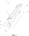
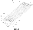
- the rotation resistances can be adjusted, such that the bendable assembly 10 can be maintained at a folding angle of 0 degree (as illustrated in FIG. 1 ), a folding angle of 180 degrees (as illustrated in FIG. 2 ), or a folding angle within a range of 0-180 degrees, thereby satisfying user requirements.
- the first damping module 16 includes multiple first damping pieces 162 stacked, and each of the multiple first damping pieces 162 defines a first notch 1622.
- An interference fit is formed between the first damping pieces 162 and at least one of the first shaft 145 and the second shaft 146 via the first notch 1622.
- the first damping pieces 162 defines two first notches 1622 at two opposite ends of the first damping pieces 162.
- the interference fit is formed between the first shaft 145 and the first damping pieces 162 via one of the two first notches 1622.
- the interference fit is formed between the second shaft 146 and the first damping pieces 162 via the other of the two first notches 1622.
- Multiple first damping pieces 162 stacked can provide a relatively large frictional force, i.e., a rotation resistance applied to the hinge module 12, and also space occupied by the hinge module 12 can be reduced, thereby facilitating arrangement of other components.
- Frictional forces may be generated between the first damping pieces 162 and the first shaft 145 and between the first damping pieces 162 and the second shaft 146, and can be adjusted by adjusting a size of the first notch 1622 or the number of the first damping pieces 162. Alternatively, the frictional forces can be adjusted by choosing the first damping pieces 162 made of relatively smooth or rough materials.
- the bendable assembly 10 includes a third connecting member 11.
- the third connecting member 11 is fixedly connected with the first connecting hinge 122 and the first shaft 145.
- the third connecting member 11 includes a first base plate 114 and a first shaft connector 112 disposed on one side of the first base plate 114.
- the third connecting member 11 has a cross section in a substantially whistle-shape.
- the first shaft connector 112 defines a through hole with a non-circular cross section, and the first shaft connector 112 cooperates with the first rod 1452 and is disposed on the first shaft 145, such that the third connecting member 11 is non-rotatable relative to the first shaft 145.
- the first base plate 114 defines two through holes to allow two first fasteners 116 to extend through.
- the linkage module 14 When the linkage module 14 is fixedly connected to the first connecting hinge 122, the first base plate 114 is embedded in the first fastening groove 1222, the first fastener 116 extends through the through hole of the first shaft connector 112 and the first fastening hole 1224 in the first fastening groove 1222, so as to accomplish a fixed connection between the third connecting member 11 and the first connecting hinge 122.
- the bendable assembly 10 includes a second damping module 18, and the second damping module 18 is rotatably disposed on at least one of the third shaft 148 and the fourth shaft 149.
- the second damping module 18 is configured to provide a rotation resistance when the hinge module 12 is switched between the bent state and the unfolded state.
- the second damping module 18 is rotatably disposed on at least one of the third shaft 148 and the fourth shaft 149. It can be understood that the second damping module 18 is rotatably disposed on the third shaft 148, or the second damping module 18 is rotatably disposed on the fourth shaft 149, or the second damping module 18 is rotatably disposed on the third shaft 148 and the fourth shaft 149. As illustrated in FIG. 2 , FIG. 4 , and FIG. 9 , the second damping module 18 is rotatably disposed on the third shaft 148 and the fourth shaft 149. More specifically, the second damping module 18 is rotatably disposed on the sixth rod 1486 and the eighth rod 1496. The second damping module 18 can provide rotation resistance for the fourth shaft 149 when the fourth shaft 149 rotates, and further provide rotation resistance when the second damping module is driven by the fourth shaft 149 to rotate relative to the third shaft 148.
- a portion of the sixth rod 1486 and a portion of the eighth rod 1496 in contact with the second damping module 18 each can be processed through a cutting process to make part of arc-shaped surfaces be flat surfaces. In this way, frictional forces between the second damping module 18 and the third shaft 148 and friction forces between the second damping module 18 and the fourth shaft 149 can be increased, thereby providing a relatively stable connection.
- the second damping module 18 can increase the rotation resistances when the second damping module 18 rotates relative to the third shaft 148 and the fourth shaft 149, thereby making the hinge module 12 more stable when switching between the bent state and the unfolded state.
- the rotation resistance can be adjusted, such that the bendable assembly 10 can be maintained at a folding angle of 0 degree (as illustrated in FIG. 1 ), a folding angle of 180 degrees (as illustrated in FIG. 2 ), or a folding angle within a range of 0-180 degrees, thereby satisfying user requirements.
- the second damping module 18 includes multiple second damping pieces 182 stacked, and each of the multiple second damping pieces 18 has a second notch 184.
- An interference fit is formed between the second damping pieces 182 and at least one of the third shaft 1448 and the fourth shaft 149 via the second notch 184.
- the second damping pieces 182 defines two second notches 184 at two opposite ends of the second damping pieces 182.
- the interference fit is formed between the second damping pieces 182 and the third shaft 148 via one of the two second notches 184.
- the interference fit is formed between the second damping pieces 182 and the fourth shaft 149 via the other of the two second notches 184.
- Multiple second damping pieces 182 stacked can provide a relatively large frictional force, i.e., a rotation resistance applied to the hinge module 12, and also the space occupied by the hinge module 12 can be reduced, thereby facilitating the arrangement of other components.
- Frictional forces may be generated between the second damping pieces 182 and the third shaft 148 and between the second damping pieces 182 and the third shaft 149, and can be adjusted by adjusting a size of the second notch 184 or a number of the second damping pieces 182. Alternatively, the frictional forces can be adjusted by choosing the second damping pieces 182 made of relatively smooth or rough materials.
- the bendable assembly 10 includes a fourth connecting member 13.
- the fourth connecting member 13 is fixedly connected with the second connecting hinge 124 and the fourth shaft 149.
- the fourth connecting member 13 includes a second base plate 134 and a second shaft connector 132 disposed on one side of the second base plate 134.
- the fourth connecting member 13 has a cross section in a substantially whistle-shape.
- the second shaft connector 132 defines a through hole with a non-circular cross section, and the second shaft connector 112 cooperates with the seventh rod 1492 and is disposed on the third shaft 148, such that the fourth connecting member 13 is non-rotatable relative to the fourth shaft 149.
- the second base plate 134 defines two through holes to allow two second fasteners 136 to extend through.
- the second base plate 134 is embedded in the second fastening groove 1242, and the second fastener 136 extends through the through hole of the second shaft connector 132 and the second fastening hole 1244 in the second fastening groove 1242, so as to accomplish a fixed connection between the fourth connecting member 13 and the second connecting hinge 124.
- the rotatable hinge 126 includes a first hinge 1262, a second hinge 1264, and a third hinge 1266.
- the first hinge 1262 is rotatably connected with the first connecting hinge 122 and the second hinge 1264.
- the second hinge 1264 is rotatably connected with the first hinge 1262 and the third hinge 1266.
- the third hinge 1266 is rotatably connected with the second connecting hinge 124 and the second hinge 1264.
- a portion of the first hinge 1262 is rotatably connected with and fitted with a portion of the first connecting hinge 122, and another portion of the first hinge 1262 is rotatably connected with and fitted with a portion of the second hinge 1264.
- the portion of the second hinge 1264 is rotatably connected with and fitted with the portion of the first hinge 1262, and another portion of the second hinge 1264 is rotatably connected with and fitted with a portion of the third hinge 1266.
- the portion of the third hinge 1266 is rotatably connected with and fitted with the another portion of the second hinge 1264, and another portion of the third hinge 1266 is rotatably connected with and fitted with a portion of the second connecting hinge 124.
- the first hinge 1262, the second hinge 1264, and the third hinge 1266 each include a hollow structure, so as to reduce the weight of the rotatable hinge 126, thereby lightening the bendable assembly 10 and the flexible display device 100.
- the first hinge 1262 is provided with first connecting portions 126a at two opposite ends of the first hinge 1262.
- the first connecting portion 126a is connected with the linkage module 14.
- the first connecting portion 126a defines two shaft holes at two opposite ends of the first connecting portion 126a through which the second rod 1456 of the first shaft 145 and the fourth rod 1466 of the second shaft 146 rotatably pass, respectively, so as to facilitate a connection between the rotatable hinge 126 and the linkage module 14.
- the first damping module 16 is arranged between the first connecting portion 126a and the first convex portion 1454 and between the first connecting portion 126a and the second convex portion 1464.
- the second hinge 1264 is provided with first accommodation spaces 126b at two opposite ends of the second hinge 1264.
- the second gear 1414 can be accommodated in the first accommodation space 126b, so as to further stabilize the second gear 1414 and prevent debris from entering the gears, thereby improving the reliability of the linkage module 14.
- the third hinge 1266 is substantially similar to the first hinge 1262 in structure.
- the third hinge 1266 is provided with second connecting portions at two opposite ends of the third hinge 1266.
- the second connecting portion of the third hinge 1266 is connected with the linkage module 14.
- the second connecting portion defines two shaft holes at two opposite ends of the second connecting portion through which the sixth shaft 1486 of the third shaft 148 and the eighth rod 1496 of the fourth shaft 149 rotatably extend, respectively, so as to facilitate the connection between the rotatable hinge 126 and the linkage module 14.
- the second damping module 18 is arranged between the second connecting portion and the third convex portion 1484 and between the second connecting portion and the fourth convex portion 1494.
- the second shaft 146 and the third shaft 148 are fixed and non-rotatable.
- the first connecting hinge 122 rotates.
- the rotation of the first connecting hinge 122 drives the first shaft 145 to rotate via the third connecting member 11.
- a rotation of the first shaft 145 enables the fourth gear 1442 and the fifth gear 1444 to rotate around the sixth gear 1446, so as to drive the first connecting member 142 and the first gear 1412 to rotate about the second shaft 146.
- a rotation of the first gear 1412 drives the second gear 1414 to rotate, such that the external force is synchronously transmitted to the third gear 1416.
- the third gear 1416 drives the second connecting member 143 to rotate, and the rotation of the second connecting member 143 drives the fourth shaft 149 to rotate.
- the fourth shaft 149 drives the ninth gear 1476 and the eighth gear 1474 to rotate around the seventh gear 1472 and drives the second connecting hinge 124 to rotate via the fourth connecting member 13, such that the first connecting hinge 122 and the second connecting hinge 124 are driven to close to each other, and a synchronous transmission process of the bendable assembly 10 is accomplished.
- the linkage module 14 has two linkage modules 14, and the two linkage modules 14 are respectively arranged at two opposite ends of the hinge module 12. In this way, the stability of the bendable assembly 10 during rotation can be improved.
- the bendable assembly 10 is provided with a first assembling member 10a, a second assembling member 10b, and a third assembling member 10c.
- first assembling member 10a, the second assembling member 10b, and the third assembling member 10c are disposed at one end of the hinge module 12 is taken for illustration.
- first assembling members 10a There are three first assembling members 10a, two second assembling members 10b, and two third assembling member 10c.
- the three first assembling members 10a are assembled at one end of the linkage module 14 at intervals and partially cover the second gear set 144 and the third gear set 147. More specifically, partially covering the second gear set 144 and the third gear set 147 can be understood as that a part of the fourth gear 1442, the entire fifth gear 1444, and a part of the sixth gear 1446 are covered by one corresponding first assembling member 10a, and a part of the seventh gear 1472, the entire eighth gear 1474, and a part of the ninth gear 1476 are covered by one corresponding first assembling member 10a.
- One of the two second assembling members 10b is fixedly disposed between the first shaft 145 and the second shaft 146, and the other one of the two second assembling members 10b is fixedly disposed between the third shaft 148 and the fourth shaft 149.
- the two second assembling members 10b accommodate the fifth gear 1444 and the eighth gear 1474 respectively, so as to improve structural stability of the second gear set 144 and the third gear set 147.
- the two first assembling members 10a on two opposite sides respectively accommodate the two second assembling members 10b.
- One of the two third assembling members 10c extends through the first shaft 145 and the second shaft 146, the other one of the two third assembling members 10c extends through the third shaft 148 and the fourth shaft 149, and the two third assembling members 10c are fixedly connected with the first damping module 16 and the second damping module 18.
- the first convex portion 1454, the second convex portion 1464, and the first damping module 16 are fixed to one of the two third assembling members 10c
- the third convex portion 1484, the fourth convex portion 1494, and the second damping module 18 are fixed to the other one of the two third assembling members 10c.
- the flexible display device 100 includes the bendable assembly 10 of any of the above embodiments and a flexible display assembly 20 disposed on the bendable assembly 10.
- the flexible display device 100 formed by arranging the flexible display assembly 20 on the bendable assembly 10 allows the flexible display assembly 20 to be changed regularly through the linkage configuration of the bendable assembly 10, thereby improving the user experience and facilitating usage of the flexible display device 100.
- the flexible display assembly 20 can be fixedly disposed on the bendable assembly 10 or detachably disposed on the bendable assembly 10.
- the flexible display assembly 20 includes a first support plate 24, a second support plate 26, and a flexible display screen 22.
- the first support plate 24 is connected with the first connecting hinge 122.
- the second support plate 26 is connected with the second connecting hinge 124.
- the flexible display screen 22 is disposed on the first support plate 24 and the second support plate 26.
- first support plate 24 and the second support plate 26 two sides of the bendable assembly 10 are respectively fixedly connected to the first support plate 24 and the second support plate 26.
- the bendable assembly 10, the first support plate 24, and the second support plate 26 corporate to provide a substantially continuous plane to facilitate the arrangement of the flexible display screen 22.
- the first support plate 24 and the second support plate 26 are made of metal or plastic. In this way, the materials of the first support plate 24 and the second support plate 26 can be diversified, which is beneficial to decrease the cost of the bendable assembly 10.
- the flexible display screen 22 includes an OLED display.
- the OLED display also has self-luminous organic electro-excited light diodes, and thus has advantages of no need for a backlight, high contrast, thin thickness, wide viewing angle, and fast response speed.
- the OLED display can also be used for flexible panels and has a wide operating temperature range and simple structure and manufacturing processes.
Landscapes
- Engineering & Computer Science (AREA)
- General Engineering & Computer Science (AREA)
- Theoretical Computer Science (AREA)
- Computer Hardware Design (AREA)
- Physics & Mathematics (AREA)
- General Physics & Mathematics (AREA)
- Human Computer Interaction (AREA)
- Signal Processing (AREA)
- Mechanical Engineering (AREA)
- Microelectronics & Electronic Packaging (AREA)
- Electromagnetism (AREA)
- Telephone Set Structure (AREA)
- Pivots And Pivotal Connections (AREA)
- Rehabilitation Tools (AREA)
Abstract
Description
- This disclosure relates to the technical field of flexible displays, and particularly to a bendable assembly and a flexible display device.
- Flexible display screens are increasingly favored by consumers due to their flexibility. The flexible display screen can be switched between a bent state and an unfolded state. Existing mechanisms can no longer meet requirements for state switch of the flexible display screen, and thus it is necessary to provide a new structural design.
- According to the present disclosure, a bendable assembly and a flexible display device are provided.
- A bendable assembly is provided according to the present disclosure. The bendable assembly includes a hinge module and a linkage module. The hinge module includes a first connecting hinge and a second connecting hinge respectively disposed at two opposite sides of the hinge module. The linkage module is connected and arranged between the first connecting hinge and the second connecting hinge. When the first connecting hinge rotates, the linkage module transmits a rotation of the first connecting hinge to the second connecting hinge to drive the second connecting hinge to rotate.
- A flexible display device is provided according to embodiments of the present disclosure. The flexible display device includes the bendable assembly provided above and a flexible display assembly disposed on the bendable assembly.
- In the bendable assembly and the flexible display device according to the embodiments of the present disclosure, when switching the hinge module between a bent state and an unfolded state, the linkage module interlocks the first connecting hinge with the second connecting hinge, it is possible to switch the hinge module between the bent state and the unfolded state by operating the first connecting hinge or the second connecting hinge, and thus it is easy to realize state switch of the bendable assembly and the flexible display device, and user experience is accordingly improved.
- Additional aspects and advantages of the present disclosure will be partly presented in the following description, partly become apparent in the following description or be appreciated in practicing of the present disclosure.
- Above and/or additional aspects and advantages of the present disclosure will be apparent and readily appreciated from the following description of embodiments with reference to the accompanying drawings, in which:
-
FIG. 1 is a schematic view of a bendable assembly in a bent state according to an embodiment of the present disclosure. -
FIG. 2 is a schematic view of the bendable assembly in an unfolded state according to an embodiment of the present disclosure. -
FIG. 3 is a partially exploded schematic view of the bendable assembly according to an embodiment of the present disclosure. -
FIG. 4 is a schematic view of a linkage module according to an embodiment of the present disclosure. -
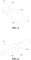
FIG. 5 is a schematic view of a first connecting member according to an embodiment of the present disclosure. -
FIG. 6 is a schematic view of a first shaft according to an embodiment of the present disclosure. -
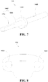
FIG. 7 is a schematic view of a second shaft according to an embodiment of the present disclosure. -
FIG. 8 is a schematic plan view of a first damping pieces according to an embodiment of the present disclosure. -
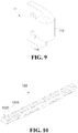
FIG. 9 is a schematic view of a third connecting member according to an embodiment of the present disclosure. -
FIG. 10 is a schematic view of a first connecting hinge according to an embodiment of the present disclosure. -
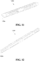
FIG. 11 is a schematic view of a first hinge according to an embodiment of the present disclosure. -
FIG. 12 is a schematic view of a second hinge according to an embodiment of the present disclosure. -
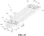
FIG. 13 is a partially exploded view of the bendable assembly of according to an embodiment of the present disclosure. -
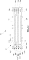
FIG. 14 is a schematic plan view of the bendable assembly according to an embodiment of the present disclosure. -
FIG. 15 is a schematic view of a first assembling member according to an embodiment of the present disclosure. -
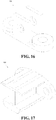
FIG. 16 is a schematic view of a second assembly member according to an embodiment of the present disclosure. -
FIG. 17 is a schematic view of a third assembly member according to an embodiment of the present disclosure. -
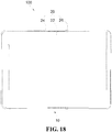
FIG. 18 is a front view of a flexible display device according to an embodiment of the present disclosure. -
FIG. 19 is a schematic rear view of the flexible display device according to an embodiment of the present disclosure. -
FIG. 20 is a schematic view of a first support plate according to an embodiment of the present disclosure. - Reference numbers indicating main members are described as follows:
flexible display device 100,bendable assembly 10,hinge module 12, first connectinghinge 122,first fastening groove 1222,first fastening hole 1224, second connectinghinge 124,second fastening groove 1242,second fastening hole 1244,rotatable hinge 126,first hinge 1262, first connectingportion 126a,second hinge 1264,first accommodation space 126b,third hinge 1266,linkage module 14,first gear set 141,first gear 1412,second gear 1414,third gear 1416, first connectingmember 142,first piece 1422,first ring part 1424,second gear set 144,fourth gear 1442,fifth gear 1444,sixth gear 1446,first shaft 145,first rod 1452,first convex portion 1454,second rod 1456,second shaft 146,third rod 1462,second convex portion 1464, first non-cylindricalportion 146a, firstcylindrical portion 146b,fourth rod 1466,third gear set 147,seventh gear 1472, eighth gear 1474,ninth gear 1476,third shaft 148, fifth rod 1482,third convex portion 1484,sixth rod 1486,fourth shaft 149,seventh rod 1492,fourth convex portion 1494,eighth rod 1496,first damping module 16,first damping pieces 162,first notch 1622,second damping module 18,second damping pieces 182, second notch 1822, third connectingmember 11,first shaft connector 112,first base plate 114,first fastener 116, fourth connectingmember 13,second shaft connector 132,second base plate 134,second fastener 136,first plate 15 ,second plate 17, first assemblingmember 10a, second assemblingmember 10b, third assemblingmember 10c,flexible display assembly 20,flexible display screen 22,first support plate 24,second support plate 26. - Embodiments of the present disclosure will be described in detail as following and examples of the embodiments will be illustrated in the accompanying drawings, where same or similar reference numerals are used to indicate same or similar members or members with same or similar functions. The embodiments described herein with reference to the accompanying drawings are exemplary, and are intended to describe the present disclosure and cannot be construed as a limitation to the present disclosure.
- In the description of the present disclosure, it is to be understood that, orientations or position relationships indicated by terms such as "center", "longitudinal", "transverse", "length", "width", "thickness", "upper", "lower", "front", "rear", "left", "right", "vertical", "horizontal", "top", "bottom", "inner", "outer", "clockwise", and "counterclockwise" are orientations or position relationships shown based on the accompanying drawings, and are merely used for describing the present disclosure and simplifying the description, rather than indicating or implying that the apparatus or element should have a particular orientation or be constructed and operated in a particular orientation, and therefore, should not be construed as a limitation to the present disclosure.
- In addition, terms "first" and "second" are used only for description purposes, and shall not be understood as indicating or suggesting relative importance or implicitly indicating a quantity of indicated technical features. Therefore, features defined by "first" and "second" may explicitly or implicitly include one or more of the above-mentioned features. In the description of the present disclosure, unless otherwise specifically limited, "multiple", "a plurality of", and "a number of" mean there are at least two elements.
- In the embodiments of the present disclosure, it is appreciated that terms "dispose", "interconnect", and "connect" should be understood in a broad sense unless otherwise specified and limited. For example, terms "interconnect" and "connect" may refer to fixedly connect, detachably connect, or integrally connect. The terms "interconnect" and "connect" may also refer to mechanically connect, electrically connect, or communicate with each other. The terms "interconnect" and "connect" may also refer to directly connect, indirectly connect through an intermediate medium, intercommunicate interiors of two elements, or interact between two elements. For those of ordinary skill in the art, the specific meanings of the above terms in the embodiments of the present disclosure can be understood according to specific situations.
- In the embodiments of the present disclosure, unless otherwise specified and limited, a first feature being disposed "above" or "below" a second feature may indicate that the first feature and the second feature are directly contacted with each other, or the first feature and the second feature are indirectly contacted via an intermediate medium. Moreover, the first feature being disposed "above" the second feature may indicate that the first feature is directly above or obliquely above the second feature, or merely indicate that the first feature is higher in horizontal height than the second feature. The first feature being disposed "below" the second feature may indicate that the first feature is directly below or obliquely below the second feature, or merely indicate that the first feature is lower in the horizontal height than the second feature.
- Various embodiments or examples are provided herein for realizing various structures. To simplify the disclosure of the present disclosure, components and arrangements of specific examples are described below, and of course, are only exemplary and are not intended to limit the present disclosure. In addition, same reference numerals and/or reference letters can be repeated in different embodiments according to the present disclosure, and such repetition is for the purpose of simplification and clarity, without indicating the relationships between various embodiments and/or arrangements in discuss. Moreover, the present disclosure provides examples of various specific processes and materials, but the applicability of other processes and/or disclosure of other materials may be appreciated by those having ordinary skill in the art.
- Referring to
FIG. 1 andFIG. 2 , abendable assembly 10 is provided according to the embodiments of the present disclosure. Thebendable assembly 10 includes ahinge module 12 and alinkage module 14. Thehinge module 12 includes a first connectinghinge 122 and a second connectinghinge 124 respectively disposed at two opposite sides of thehinge module 12. Thelinkage module 14 is connected with and arranged between the first connectinghinge 122 and the second connectinghinge 124. When the first connectinghinge 122 rotates, thelinkage module 14 transmits a rotation of the first connectinghinge 122 to the second connectinghinge 124, thus driving the second connectinghinge 124 to rotate. - According to the embodiments of the present disclosure, when switching the
hinge module 12 of thebendable assembly 10 between a bent state and an unfolded state, since thelinkage module 14 interlocks the first connectinghinge 122 with the second connectinghinge 124, it is possible to switch thehinge module 12 between the bent state and the unfolded state by operating the first connectinghinge 122 or the second connectinghinge 124, and thus it is easy to realize state switch of thebendable assembly 10 and user experience is accordingly improved. - Referring to
FIG. 2 andFIG. 3 , in some embodiments, thehinge module 12 includes arotatable hinge 126, and the first connectinghinge 122 and the second connectinghinge 124 are rotatably connected to two opposite sides of therotatable hinge 126, respectively. - In addition, the first connecting
hinge 122 and the second connectinghinge 124 are each in a substantially elongated shape and include hollow portions. A portion of the first connectinghinge 122 is rotatably connected with and fitted with a side portion of therotatable hinge 126 via shaft elements, and a portion of the second connectinghinge 124 is rotatably connected with and fitted with another side portion of therotatable hinge 126 via shaft elements, thereby improving space utilization on premise of ensuring stability of rotational connections. - The first connecting
hinge 122 definesfirst fastening grooves 1222 at two opposite ends of the first connectinghinge 122, and the second connectinghinge 124 definessecond fastening grooves 1242 at two opposite ends of the second connectinghinge 124. In thefirst fastening groove 1222, afirst fastening hole 1224 is defined. In thesecond fastening groove 1242, asecond fastening hole 1242 is defined. Afirst fastener 116 passes through therotatable hinge 126 and is locked with thefirst fastening hole 124, and asecond fastener 136 passes through therotatable hinge 126 and is locked with thesecond fastening hole 1244, thus therotatable hinge 126 connects with the first connectinghinge 122 and the second connectinghinge 124. In an embodiment, thefirst fastener 116 and thesecond fastener 136 are screws, and thefirst fastening hole 1224 and thesecond fastening hole 1244 are screw holes. Screw engagements between screws and screw holes can provide a relatively good fixed connection, and thus structural stability of thehinge module 12 can be ensured, and high repeatability and easy disassembly can be provided. - Referring to
FIG. 2 andFIG. 4 , in some embodiments, thelinkage module 14 includes a first gear set 141, a first connectingmember 142, and a second connectingmember 143. The first connectingmember 142 interlocks the first connectinghinge 122 with the first gear set 141. The second connectingmember 143 interlocks the second connectinghinge 124 with the first gear set 141. The first connectinghinge 122 can drive the first connectingmember 142 to rotate. In an embodiment, the first connectinghinge 122 drives the first connectingmember 142 to rotate as follows. The rotation of the first connectinghinge 122 drives the third connectingpiece 11 to rotate. Since the third connectingmember 11 and afirst shaft 145 are fixed together through an engagement between flat surfaces, a rotation of the third connectingmember 11 can exert a force against thefirst shaft 145, and thefirst shaft 145 subjected to the force can drive the first connectingmember 142 to rotate about asecond shaft 146. Since the first connectingmember 142 and thefirst gear 1412 are fixed by welding, a rotation of the first connectingmember 142 enables thefirst gear 1412 to rotate about thesecond shaft 146 with the first connectingmember 142. In this way, the rotation of the first connectinghinge 122 about the secondrotating shaft 146 is implemented. The first gear set 141 can transmit the rotation of the first connectingmember 142 to the second connectingmember 143 to rotate the second connectingmember 143, and a rotation of the second connectingmember 143 can drive the second connectinghinge 124 to rotate. - In this way, through connections and rotation transmissions among the first gear set 141, the first connecting
member 142, and the second connectingmember 143, a linkage configuration of thelinkage module 14 is achieved, thus simplifying position relationship among components of thelinkage module 14 and provide a clear structure and easy production and assembly of thelinkage module 14. - In an embodiment, referring to
FIG. 4 andFIG. 5 , the first connectingmember 142 includes afirst piece 1422 and twofirst ring portions 1424. The twofirst ring portions 1424 are respectively disposed, facing away from each other, on two opposite ends of thefirst piece 1422. The second connectingmember 143 is the same as the first connectingmember 142 in structure. When assembling, the first connectingmember 142 and the second connectingmember 143 are positioned in opposite directions. In an embodiment, thefirst ring portions 1424 define through holes through which thefirst shaft 145 and thesecond shaft 146 respectively pass, thereby facilitating the assembly of thebendable assembly 10. - Referring to
FIG. 4 again, the first gear set 141 includes afirst gear 1412, asecond gear 1414, and athird gear 1416. Thesecond gear 1414 is rotatably connected with thefirst gear 1412 and thethird gear 1416. Thefirst gear 1412 is fixedly connected with the first connectingmember 142. Thethird gear 1416 is fixedly connected with the second connectingmember 143. - Moreover, the
first gear 1412 and thethird gear 1416 are meshed with thesecond gear 1414. An axis about which thesecond gear 1414 rotates is perpendicular to an axis about which thefirst gear 1412 rotates and an axis about which thethird gear 1416 rotates. It can be understood that, thefirst gear 1412 rotates in a direction opposite to a direction in which thethird gear 1416 rotates. When any one of thefirst gear 1412, thesecond gear 1414, or thethird gear 1416 rotates, the other two can rotate synchronously, such that the linkage configuration of thelinkage module 14 can be realized and thebendable assembly 10 can be driven to rotate synchronously. Thefirst gear 1412 can be connected to the first connectingmember 142 by welding and thethird gear 1416 can be connected to the second connectingmember 143 by welding. Welding process is easy to implement and provides a relatively stable fixed connection. - In an embodiment, the
first gear 1412 is fixedly connected to one of the twofirst ring portions 1424 of the first connectingmember 142. Thefirst gear 1412 defines a gear through hole that can cooperate with thefirst ring portion 1424. Moreover, a cross-sectional dimension of thefirst gear 1412 is equal to or slightly smaller than that of thefirst ring portion 1424 to ensure that thelinkage module 14 has a regular appearance and normal rotation. A connection between thethird gear 1416 and the second connectingmember 143 is similar to that between thefirst gear 1412 and the first connectingmember 142, and therefore will not be described in detail herein. - Embodiments of the fixed connection between the
first gear 1412 and the first connectingmember 142 and the fixed connection between thethird gear 1416 and the second connectingmember 143 can be accomplished by using any suitable process that is not limited to welding, which can be specifically determined based on a specific embodiment. For example, thefirst gear 1412 and the first connectingmember 142 may be integrally formed and thethird gear 1416 and the second connectingmember 143 may be integrally formed, so as to improve the integrity. In another example, thefirst gear 1412 and the first connectingmember 142 can be fixedly connected by adhesive bonding, and thethird gear 1416 and the second connectingmember 143 can be fixedly connected by adhesive bonding. In an embodiment, thefirst gear 1412, thesecond gear 1414, and thethird gear 1416 are helical gears. - Referring to
FIG. 4 , in some embodiments, thelinkage module 14 includes a second gear set 144, afirst shaft 145, and asecond shaft 146. Thefirst shaft 145 is connected with the second gear set 144, the first connectingmember 142, the first connectinghinge 122, and therotatable hinge 126. Thesecond shaft 146 is connected with the second gear set 144, the first gear set 141, the first connectingmember 142, and therotatable hinge 126. - Moreover, referring to
FIGS. 2 ,4 , and6 , thefirst shaft 145 includes a firstconvex portion 1454, afirst rod 1452, and asecond rod 1456. Thefirst rod 1452 and thesecond rod 1456 are connected to two opposite sides of the firstconvex portion 1454, respectively. Thefirst rod 1452 has a cross section in a non-circular shape, such as in a flat ellipse or racetrack shape. Thesecond rod 1456 is in a substantially cylindrical shape. Thefirst rod 1452 is connected with the second gear set 144 and the first connectingmember 142, and thesecond rod 1456 is rotatably connected with the first connectinghinge 122 and therotatable hinge 126. Thefirst shaft 145 may be an integral structure or a combination of thefirst rod 1452, thesecond rod 1456, and the firstconvex portion 1454. - Referring to
FIG. 7 together, thesecond shaft 146 includes a secondconvex portion 1464, athird rod 1462, and afourth rod 1466. Thethird rod 1462 and thefourth rod 1466 are connected to two opposite sides of the secondconvex portion 1464, respectively. Thethird rod 1462 includes a firstnon-cylindrical portion 146a and a firstcylindrical portion 146b. The firstcylindrical portion 146b is connected with the firstnon-cylindrical portion 146a and the secondconvex portion 1464. Thefourth rod 1466 is in a substantially cylindrical shape. Thefirst gear 1412 and a correspondingfirst ring portion 1424 of the first connectingmember 142 are rotatably disposed on the firstcylindrical portion 146b. The firstnon-cylindrical portion 146a may have a cross section in a non-circular shape, such as in a flat ellipse shape, racetrack shape, or triangle shape. The second gear set 144 is disposed at the firstnon-cylindrical portion 146a. - The
second rod 1456 and therotatable hinge 126 are rotatably connected with the first connectinghinge 122, and thefourth rod 1466 is rotatably connected with therotatable hinge 126. - Referring to
FIG. 4 , the second gear set 144 includes afourth gear 1442, afifth gear 1444, and asixth gear 1446. Thefifth gear 1444 is rotatably connected with thefourth gear 1442 and thesixth gear 1446. Thefourth gear 1442 is disposed on thefirst shaft 145 and non-rotatable with respect to thefirst shaft 145. Thesixth gear 1446 is fixed on thesecond shaft 146 and non-rotatable relative to thesecond shaft 146. - Moreover, the
fourth gear 1442 and thesixth gear 1446 are meshed with thefifth gear 1444. An axis about which thefifth gear 1444 rotates is perpendicular to an axis about which thefourth gear 1442 rotates and an axis about which thesixth gear 1446 rotates. It can be understood that thefourth gear 1442 rotates in a direction opposite to a direction in which thesixth gear 1446 rotates. When any one of thefourth gear 1442, thefifth gear 1444, or thesixth gear 1446 rotates, the other two can rotate synchronously, such that the linkage configuration of thelinkage module 14 can be realized and thebendable assembly 10 can be driven to rotate synchronously. - The
fourth gear 1442 is fixedly connected with the other one of the twofirst ring portions 1424 of the first connectingmember 142. Thefourth gear 1442 defines a gear through hole, and a cross section of the gear through hole cooperates with a cross section of thefirst rod 1452 of thefirst shaft 145. For example, the cross section of the gear through hole in thefourth gear 1442 is in a flat ellipse shape or racetrack shape, such that thefirst rod 1452 extends through and cooperates with the gear through hole in thefourth gear 1442 to drive thelinkage module 14 to rotate. Thesixth gear 1446 is similar in structure to thefourth gear 1442, and therefore will not be described in detail. A cross-sectional dimension of thefourth gear 1442 is equal to or slightly smaller than that of thefirst ring portion 1424 to ensure that thelinkage module 14 has a regular appearance and normal rotation. - More specifically, in an embodiment as illustrated in the drawings, the
sixth gear 1446 is disposed on the firstnon-cylindrical portion 146a. Thesixth gear 1446 defines a gear through hole, where a cross section of the gear through hole cooperates with the cross section of the firstnon-cylindrical portion 146a. Thefirst gear 1412 is fixedly connected to thefirst ring portion 1424. Thefirst gear 1412 and thefirst ring portion 1424 are disposed on the firstcylindrical portion 146b and can rotate relative to the firstcylindrical portion 146b. Thefirst gear 1412 is spaced from thesixth gear 1446 by thefirst ring portion 1424, and thefourth rod 1466 rotatably extends through therotatable hinge 126. - Referring to
FIG. 2 andFIG. 4 , in some embodiments, thelinkage module 14 includes a third gear set 147, athird shaft 148, and afourth shaft 149. Thefourth shaft 149 is connected with the third gear set 147, the second connectingmember 143, the second connectinghinge 124, and therotatable hinge 126. Thethird shaft 148 is connected with the third gear set 147, the first gear set 141, the second connectingmember 143, and therotatable hinge 126. - In addition, the
third shaft 148 is substantially the same as thesecond shaft 146 in structure. Thethird shaft 148 includes a thirdconvex portion 1484, a fifth rod 1482, and asixth rod 1486. The fifth rod 1482 and thesixth rod 1486 are connected to two opposite sides of the thirdconvex portion 1484, respectively. The fifth rod 1482 includes a second non-cylindrical portion and a second cylindrical portion, the second cylindrical portion is connected with the second non-cylindrical portion and the thirdconvex portion 1484. Thesixth rod 1486 is in a substantially cylindrical shape. Thethird gear 1416 and one of the two first ring portions 1434 of the second connectingmember 143 are rotatably disposed on the second cylindrical portion. The second non-cylindrical portion may have a cross section in a non-circular shape, such as in a flat ellipse shape, racetrack shape, or triangle shape. The third gear set 147 is disposed at the second non-cylindrical portion. - The
fourth shaft 149 is substantially the same as thefirst shaft 145 in structure. Thefourth shaft 149 includes a fourthconvex portion 1494, aseventh rod 1492, and aneighth rod 1496. Theseventh rod 1492 and theeighth rod 1496 are connected to two opposite sides of the fourthconvex portion 1494, respectively. Theseventh rod 1492 has a cross section in a non-circular shape, such as in a flat ellipse or racetrack shape. Theeighth rod 1496 is in a substantially cylindrical shape. Theseventh rod 1492 is connected with the third gear set 147 and the second connectingmember 13. Theeighth rod 1496 is rotatably connected with the second connectinghinge 124 and therotatable hinge 126. Thefourth shaft 149 can be an integral structure or a combination of theseventh rod 1492, theeighth rod 1496, and the fourthconvex portion 1494. - The
eighth rod 1496 extends through therotatable hinge 126 and connects therotatable hinge 126 with the second connectinghinge 124. Theeighth rod 1496 and therotatable hinge 126 are rotatably connected with the second connectinghinge 124. Thesixth rod 1486 is rotatably connected with therotatable hinge 126. - Referring to
FIG. 4 , in some embodiments, the third gear set 147 includes aseventh gear 1472, an eighth gear 1474, and aninth gear 1476. The eighth gear 1474 is rotatably connected with theseventh gear 1472 and theninth gear 1476. Theninth gear 1476 is disposed on thefourth shaft 149 and non-rotatable relative to thefourth shaft 149. Theseventh gear 1472 is fixed on thethird shaft 148 and non-rotatable relative to thethird shaft 148. - Moreover, the
seventh gear 1472 and theninth gear 1476 are meshed with the eighth gear 1474. An axis about which the eighth gear 1474 rotates is perpendicular to an axis about which theseventh gear 1472 rotates and an axis about which theninth gear 1476 rotates. It can be understood that theseventh gear 1472 rotates in a direction opposite to a direction in which theninth gear 1476 rotates. When any one of theseventh gear 1472, the eighth gear 1474, or theninth gear 1476 rotates, the other two can rotate synchronously, such that the linkage configuration of thelinkage module 14 can be realized and thebendable assembly 10 can be driven to rotate synchronously. - The
ninth gear 1476 is fixedly connected with the other one of the two second ring portions of the second connectingmembers 143. Theninth gear 1476 defines a gear through hole in a non-cylindrical shape, such as in a flat ellipse shape or racetrack shape, such that theseventh rod 1492 extends through and cooperates with the gear through hole in theninth gear 1476 to drive thelinkage module 14 to rotate. In an embodiment, a shape of the gear through hole in theninth gear 1476 cooperates with that of theseventh rod 1492. Theseventh gear 1472 is similar in structure to theninth gear 1476, and therefore will not be described in detail. Theseventh gear 1472 is disposed on thethird shaft 148, and theseventh gear 1472 is non-rotatable relative to thethird shaft 148. A cross-sectional dimension of theninth gear 1476 is equal to or slightly smaller than that of the second ring portion to ensure the regular appearance and normal rotation of thelinkage module 14. - More specifically, in embodiments as illustrated in the drawings, the
seventh gear 1472 is disposed on the second non-cylindrical portion of thethird shaft 148. Theseventh gear 1472 defines a gear through hole that cooperates with a cross-section of the second non-cylindrical portion. Thethird gear 1416 is fixedly connected to the second ring portion and sleeved on the second cylindrical portion of thethird shaft 148, and can rotate relative to the second cylindrical portion. Thethird gear 1416 is spaced from theseventh gear 1472 by the second ring portion, and thesixth rod 1486 rotatably extends through therotatable hinge 126. - In an embodiment, in order to improve the stability of the linkage configuration of the
linkage module 14, thebendable assembly 10 includes afirst plate 15 and asecond plate 17. Compared with thesecond plate 17, thefirst plate 15 is disposed at the outside of thebendable assembly 10. Thethird rod 1462 and the fifth rod 1482 extend through thefirst plate 15 and thesecond plate 17. Thesixth gear 1446 and theseventh gear 1472 are arranged between thefirst plate 15 and thesecond plate 17. Thefirst plate 15 and thesecond plate 17 are non-rotatable relative to thesecond shaft 146 and thethird shaft 148. One of the twofirst ring portions 1424 of the first connectingmember 142 and thefirst gear 1412 are arranged between thesecond plate 17 and the secondconvex portion 1464. One of the two second ring portions of the second connectingmember 143 and thethird gear 1416 are arranged between thesecond plate 17 and the thirdconvex portion 1484. - Referring to
FIG. 2 andFIGS. 4-6 , in some embodiments, thebendable assembly 10 includes a first dampingmodule 16. The first dampingmodule 16 is rotatably disposed on at least one of thefirst shaft 145 and thesecond shaft 146. The first dampingmodule 16 is configured to provide rotation resistance when thehinge module 12 is switched between the bent state and the unfolded state. - In an embodiment, the first damping
module 16 is rotatably disposed on at least one of thefirst shaft 145 and thesecond shaft 146. It can be understood that the first dampingmodule 16 is rotatably disposed on thefirst shaft 145, or the first dampingmodule 16 is rotatably disposed on thesecond shaft 146, or the first dampingmodule 16 is rotatably disposed on both thefirst shaft 145 and thesecond shaft 146. As illustrated inFIG. 2 andFIGS. 4-6 , the first dampingmodule 16 is rotatably disposed on both thefirst shaft 145 and thesecond shaft 146. More specifically, the first dampingmodule 16 is rotatably disposed on thesecond rod 1456 and thefourth rod 1466. The first dampingmodule 16 can provide rotation resistance for thefirst shaft 145 when thefirst shaft 145 rotates and further provide rotation resistance when the first dampingmodule 16 is driven by thefirst shaft 145 to rotate relative to thesecond shaft 146. - In addition, a portion of the
second rod 1456 and a portion of thefourth rod 1466 in contact with the first dampingmodule 16 each can be processed through a cutting process to make part of arc-shaped surfaces be flat surfaces. In this way, frictional forces between the first dampingmodule 16 and thefirst shaft 145 and friction forces between the first dampingmodule 16 and thesecond shaft 146 can be increased, thereby providing a relatively stable connection. - The first damping
module 16 can increase the rotation resistances when the first dampingmodule 16 rotates relative to thefirst shaft 145 andsecond shaft 146, thereby making thehinge module 12 more stable when switching between the bent state and the unfolded state. At this point, the rotation resistances can be adjusted, such that thebendable assembly 10 can be maintained at a folding angle of 0 degree (as illustrated inFIG. 1 ), a folding angle of 180 degrees (as illustrated inFIG. 2 ), or a folding angle within a range of 0-180 degrees, thereby satisfying user requirements. - Referring to
FIG. 4 andFIG. 8 , in some embodiments, the first dampingmodule 16 includes multiple first dampingpieces 162 stacked, and each of the multiple first dampingpieces 162 defines afirst notch 1622. An interference fit is formed between the first dampingpieces 162 and at least one of thefirst shaft 145 and thesecond shaft 146 via thefirst notch 1622. - Specifically, in an embodiment illustrated in
FIG. 4 andFIG. 8 , the first dampingpieces 162 defines twofirst notches 1622 at two opposite ends of the first dampingpieces 162. The interference fit is formed between thefirst shaft 145 and the first dampingpieces 162 via one of the twofirst notches 1622. The interference fit is formed between thesecond shaft 146 and the first dampingpieces 162 via the other of the twofirst notches 1622. Multiple first dampingpieces 162 stacked can provide a relatively large frictional force, i.e., a rotation resistance applied to thehinge module 12, and also space occupied by thehinge module 12 can be reduced, thereby facilitating arrangement of other components. Frictional forces may be generated between the first dampingpieces 162 and thefirst shaft 145 and between the first dampingpieces 162 and thesecond shaft 146, and can be adjusted by adjusting a size of thefirst notch 1622 or the number of the first dampingpieces 162. Alternatively, the frictional forces can be adjusted by choosing the first dampingpieces 162 made of relatively smooth or rough materials. - Referring to
FIG. 2 ,FIG. 4 , andFIG. 9 , in some embodiments, thebendable assembly 10 includes a third connectingmember 11. The third connectingmember 11 is fixedly connected with the first connectinghinge 122 and thefirst shaft 145. - In an embodiment, the third connecting
member 11 includes afirst base plate 114 and afirst shaft connector 112 disposed on one side of thefirst base plate 114. The third connectingmember 11 has a cross section in a substantially whistle-shape. Thefirst shaft connector 112 defines a through hole with a non-circular cross section, and thefirst shaft connector 112 cooperates with thefirst rod 1452 and is disposed on thefirst shaft 145, such that the third connectingmember 11 is non-rotatable relative to thefirst shaft 145. Thefirst base plate 114 defines two through holes to allow twofirst fasteners 116 to extend through. When thelinkage module 14 is fixedly connected to the first connectinghinge 122, thefirst base plate 114 is embedded in thefirst fastening groove 1222, thefirst fastener 116 extends through the through hole of thefirst shaft connector 112 and thefirst fastening hole 1224 in thefirst fastening groove 1222, so as to accomplish a fixed connection between the third connectingmember 11 and the first connectinghinge 122. - In some embodiment, the
bendable assembly 10 includes a second dampingmodule 18, and the second dampingmodule 18 is rotatably disposed on at least one of thethird shaft 148 and thefourth shaft 149. The second dampingmodule 18 is configured to provide a rotation resistance when thehinge module 12 is switched between the bent state and the unfolded state. - In an embodiment, the second damping
module 18 is rotatably disposed on at least one of thethird shaft 148 and thefourth shaft 149. It can be understood that the second dampingmodule 18 is rotatably disposed on thethird shaft 148, or the second dampingmodule 18 is rotatably disposed on thefourth shaft 149, or the second dampingmodule 18 is rotatably disposed on thethird shaft 148 and thefourth shaft 149. As illustrated inFIG. 2 ,FIG. 4 , andFIG. 9 , the second dampingmodule 18 is rotatably disposed on thethird shaft 148 and thefourth shaft 149. More specifically, the second dampingmodule 18 is rotatably disposed on thesixth rod 1486 and theeighth rod 1496. The second dampingmodule 18 can provide rotation resistance for thefourth shaft 149 when thefourth shaft 149 rotates, and further provide rotation resistance when the second damping module is driven by thefourth shaft 149 to rotate relative to thethird shaft 148. - In addition, a portion of the
sixth rod 1486 and a portion of theeighth rod 1496 in contact with the second dampingmodule 18 each can be processed through a cutting process to make part of arc-shaped surfaces be flat surfaces. In this way, frictional forces between the second dampingmodule 18 and thethird shaft 148 and friction forces between the second dampingmodule 18 and thefourth shaft 149 can be increased, thereby providing a relatively stable connection. - The second damping
module 18 can increase the rotation resistances when the second dampingmodule 18 rotates relative to thethird shaft 148 and thefourth shaft 149, thereby making thehinge module 12 more stable when switching between the bent state and the unfolded state. At this point, the rotation resistance can be adjusted, such that thebendable assembly 10 can be maintained at a folding angle of 0 degree (as illustrated inFIG. 1 ), a folding angle of 180 degrees (as illustrated inFIG. 2 ), or a folding angle within a range of 0-180 degrees, thereby satisfying user requirements. - As illustrated in
FIG. 4 , in some embodiments, the second dampingmodule 18 includes multiple second dampingpieces 182 stacked, and each of the multiple second dampingpieces 18 has asecond notch 184. An interference fit is formed between the second dampingpieces 182 and at least one of the third shaft 1448 and thefourth shaft 149 via thesecond notch 184. - Specifically, in an embodiment illustrated in
FIG. 4 , the second dampingpieces 182 defines twosecond notches 184 at two opposite ends of the second dampingpieces 182. The interference fit is formed between the second dampingpieces 182 and thethird shaft 148 via one of the twosecond notches 184. The interference fit is formed between the second dampingpieces 182 and thefourth shaft 149 via the other of the twosecond notches 184. Multiple second dampingpieces 182 stacked can provide a relatively large frictional force, i.e., a rotation resistance applied to thehinge module 12, and also the space occupied by thehinge module 12 can be reduced, thereby facilitating the arrangement of other components. Frictional forces may be generated between the second dampingpieces 182 and thethird shaft 148 and between the second dampingpieces 182 and thethird shaft 149, and can be adjusted by adjusting a size of thesecond notch 184 or a number of the second dampingpieces 182. Alternatively, the frictional forces can be adjusted by choosing the second dampingpieces 182 made of relatively smooth or rough materials. - In some embodiments, the
bendable assembly 10 includes a fourth connectingmember 13. The fourth connectingmember 13 is fixedly connected with the second connectinghinge 124 and thefourth shaft 149. - In an embodiment, the fourth connecting
member 13 includes asecond base plate 134 and asecond shaft connector 132 disposed on one side of thesecond base plate 134. The fourth connectingmember 13 has a cross section in a substantially whistle-shape. Thesecond shaft connector 132 defines a through hole with a non-circular cross section, and thesecond shaft connector 112 cooperates with theseventh rod 1492 and is disposed on thethird shaft 148, such that the fourth connectingmember 13 is non-rotatable relative to thefourth shaft 149. Thesecond base plate 134 defines two through holes to allow twosecond fasteners 136 to extend through. When thelinkage module 14 is fixedly connected to the second connectinghinge 124, thesecond base plate 134 is embedded in thesecond fastening groove 1242, and thesecond fastener 136 extends through the through hole of thesecond shaft connector 132 and thesecond fastening hole 1244 in thesecond fastening groove 1242, so as to accomplish a fixed connection between the fourth connectingmember 13 and the second connectinghinge 124. - Referring to
FIG. 3 andFIGS. 10 to12 , in some embodiments, therotatable hinge 126 includes afirst hinge 1262, asecond hinge 1264, and athird hinge 1266. Thefirst hinge 1262 is rotatably connected with the first connectinghinge 122 and thesecond hinge 1264. Thesecond hinge 1264 is rotatably connected with thefirst hinge 1262 and thethird hinge 1266. Thethird hinge 1266 is rotatably connected with the second connectinghinge 124 and thesecond hinge 1264. - In an embodiment, a portion of the
first hinge 1262 is rotatably connected with and fitted with a portion of the first connectinghinge 122, and another portion of thefirst hinge 1262 is rotatably connected with and fitted with a portion of thesecond hinge 1264. The portion of thesecond hinge 1264 is rotatably connected with and fitted with the portion of thefirst hinge 1262, and another portion of thesecond hinge 1264 is rotatably connected with and fitted with a portion of thethird hinge 1266. The portion of thethird hinge 1266 is rotatably connected with and fitted with the another portion of thesecond hinge 1264, and another portion of thethird hinge 1266 is rotatably connected with and fitted with a portion of the second connectinghinge 124. Thefirst hinge 1262, thesecond hinge 1264, and thethird hinge 1266 each include a hollow structure, so as to reduce the weight of therotatable hinge 126, thereby lightening thebendable assembly 10 and theflexible display device 100. - The
first hinge 1262 is provided with first connectingportions 126a at two opposite ends of thefirst hinge 1262. The first connectingportion 126a is connected with thelinkage module 14. The first connectingportion 126a defines two shaft holes at two opposite ends of the first connectingportion 126a through which thesecond rod 1456 of thefirst shaft 145 and thefourth rod 1466 of thesecond shaft 146 rotatably pass, respectively, so as to facilitate a connection between therotatable hinge 126 and thelinkage module 14. The first dampingmodule 16 is arranged between the first connectingportion 126a and the firstconvex portion 1454 and between the first connectingportion 126a and the secondconvex portion 1464. - The
second hinge 1264 is provided withfirst accommodation spaces 126b at two opposite ends of thesecond hinge 1264. Thesecond gear 1414 can be accommodated in thefirst accommodation space 126b, so as to further stabilize thesecond gear 1414 and prevent debris from entering the gears, thereby improving the reliability of thelinkage module 14. Thethird hinge 1266 is substantially similar to thefirst hinge 1262 in structure. Thethird hinge 1266 is provided with second connecting portions at two opposite ends of thethird hinge 1266. The second connecting portion of thethird hinge 1266 is connected with thelinkage module 14. The second connecting portion defines two shaft holes at two opposite ends of the second connecting portion through which thesixth shaft 1486 of thethird shaft 148 and theeighth rod 1496 of thefourth shaft 149 rotatably extend, respectively, so as to facilitate the connection between therotatable hinge 126 and thelinkage module 14. The second dampingmodule 18 is arranged between the second connecting portion and the thirdconvex portion 1484 and between the second connecting portion and the fourthconvex portion 1494. - In the embodiments illustrated in the drawings, when the
bendable assembly 10 is switched between the bent state and the unfolded state, thesecond shaft 146 and thethird shaft 148 are fixed and non-rotatable. When applying an external force to the first connectinghinge 122, the first connectinghinge 122 rotates. The rotation of the first connectinghinge 122 drives thefirst shaft 145 to rotate via the third connectingmember 11. A rotation of thefirst shaft 145 enables thefourth gear 1442 and thefifth gear 1444 to rotate around thesixth gear 1446, so as to drive the first connectingmember 142 and thefirst gear 1412 to rotate about thesecond shaft 146. A rotation of thefirst gear 1412 drives thesecond gear 1414 to rotate, such that the external force is synchronously transmitted to thethird gear 1416. Thethird gear 1416 drives the second connectingmember 143 to rotate, and the rotation of the second connectingmember 143 drives thefourth shaft 149 to rotate. Thefourth shaft 149 drives theninth gear 1476 and the eighth gear 1474 to rotate around theseventh gear 1472 and drives the second connectinghinge 124 to rotate via the fourth connectingmember 13, such that the first connectinghinge 122 and the second connectinghinge 124 are driven to close to each other, and a synchronous transmission process of thebendable assembly 10 is accomplished. - In addition, in the embodiments illustrated in the drawings, the
linkage module 14 has twolinkage modules 14, and the twolinkage modules 14 are respectively arranged at two opposite ends of thehinge module 12. In this way, the stability of thebendable assembly 10 during rotation can be improved. - Referring to
FIGS. 13-17 , in order to further improve the integrity and stability of thebendable assembly 10, thebendable assembly 10 is provided with afirst assembling member 10a, asecond assembling member 10b, and athird assembling member 10c. - An example in which the first assembling
member 10a, thesecond assembling member 10b, and the third assemblingmember 10c are disposed at one end of thehinge module 12 is taken for illustration. - There are three
first assembling members 10a, twosecond assembling members 10b, and two third assemblingmember 10c. The threefirst assembling members 10a are assembled at one end of thelinkage module 14 at intervals and partially cover the second gear set 144 and the third gear set 147. More specifically, partially covering the second gear set 144 and the third gear set 147 can be understood as that a part of thefourth gear 1442, the entirefifth gear 1444, and a part of thesixth gear 1446 are covered by one corresponding first assemblingmember 10a, and a part of theseventh gear 1472, the entire eighth gear 1474, and a part of theninth gear 1476 are covered by one corresponding first assemblingmember 10a. One of the twosecond assembling members 10b is fixedly disposed between thefirst shaft 145 and thesecond shaft 146, and the other one of the twosecond assembling members 10b is fixedly disposed between thethird shaft 148 and thefourth shaft 149. The twosecond assembling members 10b accommodate thefifth gear 1444 and the eighth gear 1474 respectively, so as to improve structural stability of the second gear set 144 and the third gear set 147. The twofirst assembling members 10a on two opposite sides respectively accommodate the twosecond assembling members 10b. One of the twothird assembling members 10c extends through thefirst shaft 145 and thesecond shaft 146, the other one of the twothird assembling members 10c extends through thethird shaft 148 and thefourth shaft 149, and the twothird assembling members 10c are fixedly connected with the first dampingmodule 16 and the second dampingmodule 18. In an embodiment, the firstconvex portion 1454, the secondconvex portion 1464, and the first dampingmodule 16 are fixed to one of the twothird assembling members 10c, and the thirdconvex portion 1484, the fourthconvex portion 1494, and the second dampingmodule 18 are fixed to the other one of the twothird assembling members 10c. - Referring to
FIG. 18 , theflexible display device 100 according to the embodiments of the present disclosure includes thebendable assembly 10 of any of the above embodiments and aflexible display assembly 20 disposed on thebendable assembly 10. - The
flexible display device 100 formed by arranging theflexible display assembly 20 on thebendable assembly 10 allows theflexible display assembly 20 to be changed regularly through the linkage configuration of thebendable assembly 10, thereby improving the user experience and facilitating usage of theflexible display device 100. - In an embodiment, the
flexible display assembly 20 can be fixedly disposed on thebendable assembly 10 or detachably disposed on thebendable assembly 10. - Referring to
FIG. 19 andFIG. 20 , in some embodiments, theflexible display assembly 20 includes afirst support plate 24, asecond support plate 26, and aflexible display screen 22. Thefirst support plate 24 is connected with the first connectinghinge 122. Thesecond support plate 26 is connected with the second connectinghinge 124. Theflexible display screen 22 is disposed on thefirst support plate 24 and thesecond support plate 26. - It is noted that two sides of the
bendable assembly 10 are respectively fixedly connected to thefirst support plate 24 and thesecond support plate 26. Thebendable assembly 10, thefirst support plate 24, and thesecond support plate 26 corporate to provide a substantially continuous plane to facilitate the arrangement of theflexible display screen 22. In one example, thefirst support plate 24 and thesecond support plate 26 are made of metal or plastic. In this way, the materials of thefirst support plate 24 and thesecond support plate 26 can be diversified, which is beneficial to decrease the cost of thebendable assembly 10. - In some embodiments, the
flexible display screen 22 includes an OLED display. - In an embodiment, the OLED display also has self-luminous organic electro-excited light diodes, and thus has advantages of no need for a backlight, high contrast, thin thickness, wide viewing angle, and fast response speed. The OLED display can also be used for flexible panels and has a wide operating temperature range and simple structure and manufacturing processes.
- In the description of the specification, the description made with reference to terms such as "one embodiment", "some embodiments", "example", "specific example", or "some examples" means that a specific characteristic, structure, material or feature described with reference to the embodiment or example is included in at least one embodiment or example of the present disclosure. In this specification, exemplary descriptions of the foregoing terms do not necessarily refer to a same embodiment or example. In addition, the described specific features, structures, materials, or characteristics may be combined in a proper manner in any one or more of the embodiments or examples.
- Although the embodiments of the present disclosure are illustrated and described above, it would be appreciated by those skilled in the art that, changes, modifications, alternatives, and variants can be made in the embodiments without departing from principles and purposes of the present disclosure, and the scope of present disclosure is defined by the claims and their equivalents.
Claims (20)
- A bendable assembly comprising:a hinge module, comprising a first connecting hinge and a second connecting hinge respectively disposed at two opposite sides of the hinge module; anda linkage module connected and arranged between the first connecting hinge and the second connecting hinge; whereinwhen the first connecting hinge rotates, the linkage module transmits a rotation of the first connecting hinge to the second connecting hinge to drive the second connecting hinge to rotate.
- The bendable assembly of claim 1, wherein
the linkage module comprises a plurality of linked gears; and
the hinge module bends to enable at least two of the plurality of linked gears arranged at opposite outermost sides of the linkage module to rotate in opposite directions to drive the second connecting hinge and the first connecting hinge to rotate toward each other. - The bendable assembly of claim 2, wherein
the linkage module comprises a first gear set, a first connecting member, and a second connecting member;
the first connecting member interlocks the first connecting hinge with the first gear set, and the second connecting member interlocks the second connecting hinge with the first gear set; and
the first connecting hinge enables to drive the first connecting member to rotate, the first gear set enables to transmit a rotation of the first connecting member to the second connecting member, and the second connecting member then drives the second connecting hinge to rotate. - The bendable assembly of claim 3, wherein the first gear set comprises a first gear, a second gear, and a third gear, wherein the second gear rotatably connects with the first gear and the third gear, the first gear fixedly connects with the first connecting member, and the third gear fixedly connects with the second connecting member.
- The bendable assembly of claim 4, wherein an axis about which the second gear rotates is perpendicular to an axis about which the first gear rotates and an axis about which the third gear rotates.
- The bendable assembly of claim 3, wherein
the linkage module comprises a second gear set, a first shaft, and a second shaft;
the first shaft connects with the second gear set, the first connecting member, and the first connecting hinge; and
the second shaft connects with the second gear set, the first gear set, and the first connecting member. - The bendable assembly of claim 6, wherein the second gear set comprises a fourth gear, a fifth gear, and a sixth gear, wherein the fifth gear rotatably connects with the fourth gear and the sixth gear, the fourth gear disposes on the first shaft and non-rotatable with respect to the first shaft, and the sixth gear fixes on the second shaft and non-rotatable relative to the second shaft.
- The bendable assembly of claim 7, wherein an axis about which the fifth gear rotates is perpendicular to an axis about which the fourth gear rotates and an axis about which the sixth gear rotates.
- The bendable assembly of claim 6, wherein the bendable assembly comprises a first damping module, wherein the first damping module rotatably disposes on at least one of the first shaft and the second shaft, and the first damping module is configured to provide rotation resistance when the hinge module is switched between a bent state and an unfolded state.
- The bendable assembly of claim 9, wherein the first damping module comprises a plurality of first damping pieces stacked, wherein each of the plurality of first damping pieces defines a first notch, wherein an interference fit is formed between the first damping pieces and at least one of the first shaft and the second shaft via the first notch.
- The bendable assembly of claim 6, wherein the bendable assembly comprises a third connecting member, wherein the third connecting member fixedly connects with the first connecting hinge and the first shaft.
- The bendable assembly of claim 3, wherein
the linkage module comprises a third gear set, a third shaft, and a fourth shaft;
the fourth shaft connects with the third gear set, the second connecting member, and the second connecting hinge; and
the third shaft connects with the third gear set, the first gear set, and the second connecting member. - The bendable assembly of claim 12, wherein the third gear set comprises a seventh gear, an eighth gear, and a ninth gear, wherein the eighth gear rotatably connects with the seventh gear and the ninth gear, the seventh gear fixes on the third shaft and non-rotatable relative to the third shaft, and the ninth gear disposes on the fourth shaft and non-rotatable relative to the fourth shaft.
- The bendable assembly of claim 13, wherein an axis about which the eighth gear rotates is perpendicular to an axis about which the seventh gear rotates and an axis about which the ninth gear rotates.
- The bendable assembly of any of claims 5, 8, or 14, wherein the second gear, the fifth gear, and the eighth gear are all helical gears.
- The bendable assembly of claim 12, wherein the bendable assembly comprises a second damping module, wherein the second damping module rotatably disposes on at least one of the third shaft and the fourth shaft, and the second damping module is operable to provide rotation resistance when the hinge module is switched between a bent state and an unfolded state.
- The bendable assembly of claim 16, wherein the second damping module comprises a plurality of second damping pieces stacked, each of the plurality of second damping pieces has a second notch, wherein an interference fit is formed between the second damping pieces and at least one of the third shaft and the fourth shaft via the second notch.
- The bendable assembly of claim 12, wherein the bendable assembly comprises a fourth connecting member, wherein the fourth connecting member fixedly connects with the second connecting hinge and the fourth shaft.
- The bendable assembly of claim 2, wherein
the hinge module comprises a rotatable hinge, wherein the first connecting hinge and the second connecting hinge respectively rotatably connect to two opposite sides of the rotatable hinge; and
the rotatable hinge comprises a first hinge, a second hinge, and a third hinge, wherein the first hinge rotatably connects with the first connecting hinge and the second hinge, the second hinge rotatably connects with the first hinge and the third hinge, and the third hinge rotatably connects with the second connecting hinge and the second hinge. - A flexible display device comprising the bendable assembly of any of claims 1 to 19 two and arranged and a flexible display assembly disposed on the bendable assembly.
Applications Claiming Priority (4)
| Application Number | Priority Date | Filing Date | Title |
|---|---|---|---|
| PCT/CN2018/078691 WO2019173941A1 (en) | 2018-03-12 | 2018-03-12 | Bending assembly and flexible display device |
| PCT/CN2018/078689 WO2019173939A1 (en) | 2018-03-12 | 2018-03-12 | Buckling assembly and flexible display device |
| PCT/CN2018/078690 WO2019173940A1 (en) | 2018-03-12 | 2018-03-12 | Bending assembly and flexible display device |
| PCT/CN2018/093765 WO2019174156A1 (en) | 2018-03-12 | 2018-06-29 | Bending component and flexible display device |
Publications (1)
| Publication Number | Publication Date |
|---|---|
| EP3767611A1 true EP3767611A1 (en) | 2021-01-20 |
Family
ID=66693583
Family Applications (2)
| Application Number | Title | Priority Date | Filing Date |
|---|---|---|---|
| EP18909689.4A Withdrawn EP3767611A1 (en) | 2018-03-12 | 2018-06-29 | Bending component and flexible display device |
| EP18909662.1A Withdrawn EP3767610A4 (en) | 2018-03-12 | 2018-09-29 | Bendable device, housing, and electronic device |
Family Applications After (1)
| Application Number | Title | Priority Date | Filing Date |
|---|---|---|---|
| EP18909662.1A Withdrawn EP3767610A4 (en) | 2018-03-12 | 2018-09-29 | Bendable device, housing, and electronic device |
Country Status (4)
| Country | Link |
|---|---|
| US (2) | US20200409422A1 (en) |
| EP (2) | EP3767611A1 (en) |
| CN (9) | CN112313729A (en) |
| WO (5) | WO2019174156A1 (en) |
Cited By (2)
| Publication number | Priority date | Publication date | Assignee | Title |
|---|---|---|---|---|
| CN114673907A (en) * | 2022-03-23 | 2022-06-28 | 湖北长江新型显示产业创新中心有限公司 | A display device and support assembly |
| EP4187354A1 (en) * | 2021-11-24 | 2023-05-31 | Beijing Xiaomi Mobile Software Co., Ltd. | Coupling device and terminal equipment |
Families Citing this family (62)
| Publication number | Priority date | Publication date | Assignee | Title |
|---|---|---|---|---|
| CN207543155U (en) * | 2017-11-03 | 2018-06-26 | 杭州安费诺飞凤通信部品有限公司 | The hinge of interior flexible screen mobile terminal and interior flexible screen mobile terminal |
| CN112313729A (en) * | 2018-03-12 | 2021-02-02 | 深圳市柔宇科技股份有限公司 | Bending components and flexible display devices |
| ES2950193T3 (en) * | 2019-02-19 | 2023-10-05 | Samsung Electronics Co Ltd | Hinge module including retaining structure and foldable electronic device including hinge module |
| US11142932B2 (en) * | 2019-03-12 | 2021-10-12 | Compal Electronics, Inc. | Dual-shaft hinge module and portable electronic device |
| WO2021000286A1 (en) * | 2019-07-03 | 2021-01-07 | 深圳市柔宇科技有限公司 | Hinge, hinge device and electronic device |
| CN211778479U (en) * | 2019-07-15 | 2020-10-27 | 深圳市柔宇科技有限公司 | Folding device and electronic equipment |
| CN112230713A (en) * | 2019-07-15 | 2021-01-15 | 深圳市柔宇科技有限公司 | Folding device and electronic equipment |
| CN113366927A (en) * | 2019-07-15 | 2021-09-07 | 深圳市柔宇科技股份有限公司 | Folding device and electronic equipment |
| TWI688324B (en) * | 2019-08-02 | 2020-03-11 | 宏碁股份有限公司 | Foldable electronic device |
| US11243578B2 (en) * | 2019-08-02 | 2022-02-08 | Dell Products L.P. | Gear synchronized dual axis pivot hinge |
| US11294431B2 (en) | 2019-08-02 | 2022-04-05 | Dell Products L.P. | Synchronized dual axis pivot hinge |
| US11586243B2 (en) | 2019-08-02 | 2023-02-21 | Dell Products L.P. | Information handling system flexible display rotational orientation monitoring and management |
| CN110706593A (en) * | 2019-09-12 | 2020-01-17 | 深圳世竟液态金属有限公司 | Support structure and foldable display device |
| CN110647215B (en) * | 2019-09-29 | 2021-04-13 | 联想(北京)有限公司 | Rotating shaft and electronic equipment |
| TWI711365B (en) * | 2019-11-14 | 2020-11-21 | 宏碁股份有限公司 | Hinge module and portable electronic device |
| TWI746239B (en) * | 2019-11-25 | 2021-11-11 | 仁寶電腦工業股份有限公司 | Torque hinge module |
| CN111022481B (en) * | 2019-12-11 | 2021-10-22 | 联想(北京)有限公司 | Rotating shaft assembly and electronic equipment |
| CN114338864A (en) | 2020-09-30 | 2022-04-12 | 华为技术有限公司 | Folding device and electronic equipment |
| CN113883156A (en) | 2020-07-01 | 2022-01-04 | 华为技术有限公司 | Folding module and folding electronic equipment |
| CN113141422B (en) | 2020-01-19 | 2022-09-16 | 华为技术有限公司 | Foldable mobile terminal |
| CN114449068A (en) | 2020-10-31 | 2022-05-06 | 华为技术有限公司 | Hinge mechanism and foldable electronic equipment |
| CN110969946B (en) * | 2019-12-20 | 2022-07-08 | 深圳市长盈精密技术股份有限公司 | External folding hinge and folding display device |
| EP4395289B1 (en) * | 2019-12-27 | 2026-02-04 | Huawei Technologies Co., Ltd. | Electronic device |
| CN111147637B (en) * | 2019-12-27 | 2021-04-09 | Oppo广东移动通信有限公司 | Rotating assembly and electronic equipment |
| CN111047995B (en) * | 2019-12-30 | 2022-07-26 | 厦门天马微电子有限公司 | Flexible display device |
| TWI755680B (en) * | 2020-01-22 | 2022-02-21 | 富世達股份有限公司 | The supporting structure of the rotating shaft chain group |
| TWI727637B (en) * | 2020-01-31 | 2021-05-11 | 友達光電股份有限公司 | Bendable display device |
| TWI780599B (en) * | 2020-03-09 | 2022-10-11 | 仁寶電腦工業股份有限公司 | Hinge mechanism and foldable electronic device |
| CN113496651B (en) * | 2020-04-07 | 2023-08-25 | Oppo广东移动通信有限公司 | Flexible screen support device, flexible screen module and electronic equipment |
| TWI742811B (en) * | 2020-04-20 | 2021-10-11 | 仁寶電腦工業股份有限公司 | Folding-type electronic device |
| CN111583791B (en) * | 2020-05-07 | 2022-04-26 | 昆山国显光电有限公司 | Flexible screen supporting device and flexible screen terminal |
| CN111613137B (en) * | 2020-05-12 | 2022-04-01 | Oppo(重庆)智能科技有限公司 | Interior folding flexible screen strutting arrangement, interior folding flexible screen module and electronic equipment |
| CN111609029B (en) * | 2020-05-22 | 2021-05-04 | 深圳市柔宇科技有限公司 | Folding device and flexible electronic equipment |
| CN111462636B (en) * | 2020-05-28 | 2025-03-18 | 京东方科技集团股份有限公司 | Support device and bendable device |
| WO2021246535A1 (en) * | 2020-06-01 | 2021-12-09 | 엘지전자 주식회사 | Flexible display device |
| CN111770217A (en) * | 2020-06-08 | 2020-10-13 | Oppo广东移动通信有限公司 | Rotating mechanism and its electronic equipment |
| CN113803575B (en) * | 2020-06-12 | 2025-09-16 | Drnc控股公司 | Flexible screen supporting device and intelligent terminal |
| CN113851040B (en) * | 2020-06-28 | 2022-11-15 | Oppo广东移动通信有限公司 | Electronic equipment |
| CN111726442B (en) * | 2020-06-30 | 2021-06-18 | 东莞斯蒙奇智能科技有限公司 | Flexible screen folding mechanism capable of being turned over manually and uniformly and electronic equipment |
| CN111810518B (en) * | 2020-07-06 | 2021-10-01 | 维沃移动通信有限公司 | A connection component, chain component and electronic equipment |
| CN113948000A (en) * | 2020-07-17 | 2022-01-18 | 深圳市柔宇科技股份有限公司 | Folding device and electronic equipment |
| CN112198935B (en) * | 2020-09-01 | 2022-03-11 | 杭州丰衡机电有限公司 | Server convenient to install |
| KR102849762B1 (en) | 2020-09-14 | 2025-08-26 | 삼성전자주식회사 | Structure of Link Hinge and electronic device including the same |
| CN112581864B (en) * | 2020-09-24 | 2025-03-11 | 东莞市驭舟精密科技有限公司 | A rotating shaft mechanism for a flexible screen |
| CN112216212B (en) * | 2020-10-15 | 2022-08-26 | 京东方科技集团股份有限公司 | Middle frame assembly and display device |
| CN115938229B (en) * | 2020-11-28 | 2023-09-29 | 华为技术有限公司 | Edge protection structure and folding display terminal |
| CN112696426B (en) * | 2020-12-22 | 2022-03-11 | 维沃移动通信有限公司 | Hinge mechanism, folding mechanism and electronic equipment |
| CN215890763U (en) | 2021-07-05 | 2022-02-22 | 武汉华星光电半导体显示技术有限公司 | Hinge, flexible display panel and electronic device |
| CN216241794U (en) * | 2021-07-05 | 2022-04-08 | 武汉华星光电半导体显示技术有限公司 | Hinge, flexible display panel and electronic device |
| CN113551109B (en) * | 2021-07-13 | 2022-08-30 | 深圳特为科创信息技术有限公司 | Bank wind-control multi-screen interconnection display system |
| CN115643324B (en) * | 2021-07-20 | 2025-02-14 | 深圳市富世达通讯有限公司 | Hinge |
| US12019482B2 (en) | 2021-07-30 | 2024-06-25 | Wuhan China Star Optoelectronics Semiconductor Display Technology Co., Ltd. | Flexible display panel, electronic device, and hinge |
| CN113314036B (en) * | 2021-07-30 | 2022-01-04 | 武汉华星光电半导体显示技术有限公司 | Flexible display panel, electronic device and hinge |
| CN116391084B (en) * | 2021-10-25 | 2026-02-13 | 京东方科技集团股份有限公司 | Support structure and display device |
| KR20230061014A (en) * | 2021-10-28 | 2023-05-08 | 삼성전자주식회사 | Electronic device including opening and closing member |
| CN114078390B (en) * | 2021-11-15 | 2023-02-28 | 武汉华星光电半导体显示技术有限公司 | Folding display device |
| CN116137634B (en) * | 2021-11-16 | 2025-10-03 | 北京小米移动软件有限公司 | Hinge component, folding screen assembly and foldable terminal device |
| US12219723B2 (en) * | 2022-06-14 | 2025-02-04 | Microsoft Technology Licensing, Llc | Hinged device having slot defined hinge trajectories |
| TWI819786B (en) * | 2022-09-09 | 2023-10-21 | 群邁通訊股份有限公司 | Hinged structure and terminal device |
| TWM641966U (en) * | 2022-11-22 | 2023-06-01 | 信錦企業股份有限公司 | Foldable electronic device |
| CN116215399B (en) * | 2023-03-22 | 2026-05-12 | 上海天马微电子有限公司 | Display device and control method thereof |
| US20240401390A1 (en) * | 2023-06-01 | 2024-12-05 | Sinher Technology Inc. | Double-shaft hinge with single-shaft implementation mode |
Family Cites Families (55)
| Publication number | Priority date | Publication date | Assignee | Title |
|---|---|---|---|---|
| US5697125A (en) * | 1995-11-27 | 1997-12-16 | Reell Precision Manufacturing Corporation | Clip friction hinge |
| US6615523B1 (en) * | 1999-12-06 | 2003-09-09 | Adrian Curbelo | Reversible A-frame sign |
| CN2476043Y (en) * | 2001-05-15 | 2002-02-06 | 英保达股份有限公司 | Shaft structure |
| JP4638764B2 (en) * | 2005-04-21 | 2011-02-23 | 株式会社ストロベリーコーポレーション | Hinge mechanism and portable terminal |
| US7695267B2 (en) * | 2006-05-16 | 2010-04-13 | Dynaflex International | Rib forming apparatus and method |
| CN102109004B (en) * | 2009-12-24 | 2013-04-10 | 兆利科技工业股份有限公司 | Wrapped hub |
| US8787016B2 (en) * | 2011-07-06 | 2014-07-22 | Apple Inc. | Flexible display devices |
| CN202326676U (en) * | 2011-10-18 | 2012-07-11 | 宏碁股份有限公司 | Foldable electronic device and pivot structure |
| CN103161819B (en) * | 2012-02-27 | 2015-04-29 | 联想(北京)有限公司 | Hinge device and electronic device comprising hinge device |
| KR101452871B1 (en) * | 2013-01-11 | 2014-10-22 | (주) 프렉코 | Foldable Flexible Display Device |
| WO2013080191A2 (en) * | 2013-02-22 | 2013-06-06 | Wasfi Alshdaifat | Foldable flexible display (tri-phone) |
| KR101727971B1 (en) * | 2014-02-21 | 2017-04-18 | 삼성전자주식회사 | Foldable device |
| US10975603B2 (en) * | 2014-06-12 | 2021-04-13 | Microsoft Technology Licensing, Llc | Flexible display computing device |
| TWI532930B (en) * | 2014-08-15 | 2016-05-11 | First Dome Corp | Multi - joint synchronous shaft structure |
| CN105468091B (en) * | 2014-09-03 | 2019-01-15 | 联想(北京)有限公司 | Electronic equipment and attachment device |
| US9625952B2 (en) * | 2014-09-10 | 2017-04-18 | Lenovo (Singapore) Pte. Ltd. | Hinge assemblies |
| KR102319835B1 (en) * | 2014-09-22 | 2021-11-01 | 엘지디스플레이 주식회사 | Foldable display apparatus |
| CN104482037A (en) * | 2014-11-25 | 2015-04-01 | 泽台精密电子工业(深圳)有限公司 | Rotary shaft device and folding electronic device with same |
| CN104485055B (en) * | 2014-12-24 | 2017-02-22 | 华勤通讯技术有限公司 | Auxiliary spreading device for flexible screen |
| CN105822658B (en) * | 2015-01-07 | 2018-11-09 | 联想(北京)有限公司 | Revolving joint and the computer including the revolving joint and electronic equipment |
| CN104750189B (en) * | 2015-03-31 | 2019-03-29 | 联想(北京)有限公司 | A kind of attachment device, electronic equipment and electronic apparatus combination |
| CN106255935B (en) * | 2015-04-09 | 2019-09-24 | 三星电子株式会社 | Folding device |
| WO2016209247A1 (en) * | 2015-06-26 | 2016-12-29 | Hewlett-Packard Development Company, L.P. | Hinge for a foldable display unit |
| KR101762131B1 (en) * | 2015-08-21 | 2017-07-27 | (주) 프렉코 | Hinge Device for Flexible Display |
| KR101762132B1 (en) * | 2015-08-21 | 2017-07-27 | (주) 프렉코 | Hinge Device with The Linkage Structure for Flexible Display |
| KR102366516B1 (en) * | 2015-08-31 | 2022-02-22 | 엘지디스플레이 주식회사 | Foldable display apparatus |
| CN205047647U (en) * | 2015-09-25 | 2016-02-24 | 昆山玮硕恒基电子科技有限公司 | Variable rotatory torsion biax is with moving pivot mechanism |
| CN107210012A (en) * | 2015-12-15 | 2017-09-26 | 深圳市柔宇科技有限公司 | A kind of flexible display screen and terminal device |
| CN105549690B (en) * | 2015-12-29 | 2018-01-19 | 广东欧珀移动通信有限公司 | Folding mobile terminal |
| CN105549689B (en) * | 2015-12-29 | 2018-01-19 | 广东欧珀移动通信有限公司 | a folding terminal |
| EP3399516A4 (en) * | 2015-12-31 | 2019-08-14 | Shenzhen Royole Technologies Co. Ltd. | Bendable mobile terminal |
| CN205446377U (en) * | 2016-02-03 | 2016-08-10 | 杭州安费诺飞凤通信部品有限公司 | Flexible screen bearing structure and mobile terminal |
| CN205721487U (en) * | 2016-03-21 | 2016-11-23 | 杭州安费诺飞凤通信部品有限公司 | Flexible screen supporting hinges and mobile terminal |
| CN205654706U (en) * | 2016-04-15 | 2016-10-19 | 东莞市劲丰电子有限公司 | an outer curved shaft |
| CN205847346U (en) * | 2016-06-07 | 2016-12-28 | 杭州安费诺飞凤通信部品有限公司 | The hinge of a kind of flexible screen mobile terminal, hinge means and flexible screen mobile terminal |
| KR102460466B1 (en) * | 2016-07-06 | 2022-10-28 | 삼성전자주식회사 | Foldable electronic device including flexible display |
| EP3488726A4 (en) * | 2016-07-19 | 2019-07-31 | Shenzhen Royole Technologies Co., Ltd. | Flexible device |
| CN106254598A (en) * | 2016-09-30 | 2016-12-21 | 珠海市魅族科技有限公司 | A kind of foldable flexible screen electronic equipment |
| CN206257154U (en) * | 2016-10-14 | 2017-06-16 | 新日兴股份有限公司 | clamshell electronics |
| TWM538309U (en) * | 2016-11-18 | 2017-03-11 | First Dome Corp | Hinge device |
| US9874906B1 (en) * | 2016-12-09 | 2018-01-23 | First Dome Corporation | Bendable display apparatus and supporting device |
| CN206369990U (en) * | 2016-12-12 | 2017-08-01 | 珠海市魅族科技有限公司 | Electronic installation |
| CN207053559U (en) * | 2017-01-26 | 2018-02-27 | 广东欧珀移动通信有限公司 | Housing assembly, display device and mobile terminal |
| CN106814813A (en) * | 2017-03-06 | 2017-06-09 | 联想(北京)有限公司 | Rotating assembly and electronic equipment |
| CN106888297B (en) * | 2017-03-20 | 2022-11-15 | 北京微格互动科技股份有限公司 | Mobile terminal support |
| US9848502B1 (en) * | 2017-03-24 | 2017-12-19 | Shin Zu Shing Co., Ltd. | Hinge assembly and foldable display device using the same |
| CN206559426U (en) * | 2017-03-24 | 2017-10-13 | 广东欧珀移动通信有限公司 | Rotating assembly, folding screen assembly and mobile terminal |
| CN107135288B (en) * | 2017-04-25 | 2020-03-24 | 珠海市魅族科技有限公司 | Folding terminal with flexible screen |
| CN107277197B (en) * | 2017-05-26 | 2020-09-15 | 珠海市魅族科技有限公司 | Hinge structure and mobile terminal |
| CN107181838B (en) * | 2017-05-26 | 2020-11-10 | 宇龙计算机通信科技(深圳)有限公司 | Flexible display device and mobile terminal with same |
| CN107170373A (en) * | 2017-06-29 | 2017-09-15 | 武汉天马微电子有限公司 | A flexible display device |
| CN107690010B (en) * | 2017-09-06 | 2023-12-12 | Oppo广东移动通信有限公司 | Flexible screen folding mobile terminal and folding structure assembly thereof |
| CN207268258U (en) * | 2017-09-22 | 2018-04-24 | 深圳市柔宇科技有限公司 | Bending structure and bending display device |
| CN107654484A (en) * | 2017-09-26 | 2018-02-02 | 联想(北京)有限公司 | A kind of connection member and flexible display screen, flexible electronic devices |
| CN112313729A (en) * | 2018-03-12 | 2021-02-02 | 深圳市柔宇科技股份有限公司 | Bending components and flexible display devices |
-
2018
- 2018-06-29 CN CN201880090430.3A patent/CN112313729A/en active Pending
- 2018-06-29 CN CN201821040454.1U patent/CN208919053U/en not_active Expired - Fee Related
- 2018-06-29 WO PCT/CN2018/093765 patent/WO2019174156A1/en not_active Ceased
- 2018-06-29 EP EP18909689.4A patent/EP3767611A1/en not_active Withdrawn
- 2018-09-29 EP EP18909662.1A patent/EP3767610A4/en not_active Withdrawn
- 2018-09-29 CN CN201821607420.6U patent/CN209861327U/en not_active Expired - Fee Related
- 2018-09-29 CN CN201821607416.XU patent/CN209414382U/en not_active Expired - Fee Related
- 2018-09-29 WO PCT/CN2018/108626 patent/WO2019174219A1/en not_active Ceased
- 2018-09-29 WO PCT/CN2018/108667 patent/WO2019174220A1/en not_active Ceased
- 2018-09-29 CN CN201880090446.4A patent/CN112204496A/en active Pending
- 2018-09-29 CN CN201880090439.4A patent/CN112041916A/en active Pending
- 2018-10-26 CN CN201821757377.1U patent/CN209419662U/en not_active Expired - Fee Related
- 2018-10-26 WO PCT/CN2018/112147 patent/WO2019174242A1/en not_active Ceased
- 2018-10-26 CN CN201880090433.7A patent/CN112313927A/en active Pending
-
2019
- 2019-02-28 CN CN201920259391.7U patent/CN209625666U/en not_active Expired - Fee Related
- 2019-02-28 WO PCT/CN2019/076551 patent/WO2019174478A1/en not_active Ceased
-
2020
- 2020-09-09 US US17/016,174 patent/US20200409422A1/en not_active Abandoned
- 2020-09-09 US US17/015,742 patent/US20200409431A1/en not_active Abandoned
Cited By (3)
| Publication number | Priority date | Publication date | Assignee | Title |
|---|---|---|---|---|
| EP4187354A1 (en) * | 2021-11-24 | 2023-05-31 | Beijing Xiaomi Mobile Software Co., Ltd. | Coupling device and terminal equipment |
| CN114673907A (en) * | 2022-03-23 | 2022-06-28 | 湖北长江新型显示产业创新中心有限公司 | A display device and support assembly |
| CN114673907B (en) * | 2022-03-23 | 2023-08-08 | 湖北长江新型显示产业创新中心有限公司 | A display device and support assembly |
Also Published As
| Publication number | Publication date |
|---|---|
| US20200409422A1 (en) | 2020-12-31 |
| CN209861327U (en) | 2019-12-27 |
| CN209419662U (en) | 2019-09-20 |
| CN112204496A (en) | 2021-01-08 |
| WO2019174478A1 (en) | 2019-09-19 |
| CN209625666U (en) | 2019-11-12 |
| EP3767610A4 (en) | 2021-12-15 |
| WO2019174156A1 (en) | 2019-09-19 |
| EP3767610A1 (en) | 2021-01-20 |
| WO2019174242A1 (en) | 2019-09-19 |
| CN209414382U (en) | 2019-09-20 |
| US20200409431A1 (en) | 2020-12-31 |
| WO2019174220A1 (en) | 2019-09-19 |
| CN112313927A (en) | 2021-02-02 |
| CN112041916A (en) | 2020-12-04 |
| CN208919053U (en) | 2019-05-31 |
| WO2019174219A1 (en) | 2019-09-19 |
| CN112313729A (en) | 2021-02-02 |
Similar Documents
| Publication | Publication Date | Title |
|---|---|---|
| US20200409431A1 (en) | Bendable assembly and flexible display device | |
| US20200413557A1 (en) | Bendable assembly and flexible display device | |
| US20220174830A1 (en) | Electronic device and foldable assembly | |
| US11914430B2 (en) | Support apparatus for flexible screen, foldable display module, and display device | |
| US11009061B2 (en) | Hidden type split hinge | |
| WO2020173341A1 (en) | Rotating device, housing and electronic device | |
| JP4407722B2 (en) | Display device | |
| US20230164937A1 (en) | Display device | |
| US20080105070A1 (en) | Display Screen Turning Apparatus | |
| CN113424248A (en) | Linkage mechanism, folding device and electronic equipment | |
| KR101861077B1 (en) | Hinge and flexible diplay device including the same | |
| US10244653B2 (en) | Multi-axis rotary shaft link device | |
| US20220124923A1 (en) | Mid-frame assembly and display device | |
| US12625525B2 (en) | Rotating shaft apparatus, foldable housing and electronic device | |
| KR20200089557A (en) | Advertising device having trigonal rotatory billboard | |
| US20250013268A1 (en) | Folding device, folding housing, and electronic device | |
| US20180032110A1 (en) | Rotary shaft link device | |
| CN115899485B (en) | Display device | |
| JP4390820B2 (en) | Rotating advertising equipment | |
| CN112599014B (en) | A display module and display device | |
| CN214202972U (en) | Foldable display device | |
| WO2019178815A1 (en) | Supporting structure and flexible display device | |
| CN117765818A (en) | Display modules and display devices | |
| CN224214651U (en) | Connection structure and connecting piece | |
| CN214381060U (en) | Rotation regulation structure, camera and electronic equipment |
Legal Events
| Date | Code | Title | Description |
|---|---|---|---|
| STAA | Information on the status of an ep patent application or granted ep patent |
Free format text: STATUS: THE INTERNATIONAL PUBLICATION HAS BEEN MADE |
|
| PUAI | Public reference made under article 153(3) epc to a published international application that has entered the european phase |
Free format text: ORIGINAL CODE: 0009012 |
|
| STAA | Information on the status of an ep patent application or granted ep patent |
Free format text: STATUS: REQUEST FOR EXAMINATION WAS MADE |
|
| 17P | Request for examination filed |
Effective date: 20201008 |
|
| AK | Designated contracting states |
Kind code of ref document: A1 Designated state(s): AL AT BE BG CH CY CZ DE DK EE ES FI FR GB GR HR HU IE IS IT LI LT LU LV MC MK MT NL NO PL PT RO RS SE SI SK SM TR |
|
| AX | Request for extension of the european patent |
Extension state: BA ME |
|
| DAV | Request for validation of the european patent (deleted) | ||
| DAX | Request for extension of the european patent (deleted) | ||
| STAA | Information on the status of an ep patent application or granted ep patent |
Free format text: STATUS: THE APPLICATION HAS BEEN WITHDRAWN |
|
| 18W | Application withdrawn |
Effective date: 20210805 |