EP3767398A1 - Solar panel, display device, and watch - Google Patents
Solar panel, display device, and watch Download PDFInfo
- Publication number
- EP3767398A1 EP3767398A1 EP19767151.4A EP19767151A EP3767398A1 EP 3767398 A1 EP3767398 A1 EP 3767398A1 EP 19767151 A EP19767151 A EP 19767151A EP 3767398 A1 EP3767398 A1 EP 3767398A1
- Authority
- EP
- European Patent Office
- Prior art keywords
- solar panel
- dial
- power
- disposed
- areas
- Prior art date
- Legal status (The legal status is an assumption and is not a legal conclusion. Google has not performed a legal analysis and makes no representation as to the accuracy of the status listed.)
- Pending
Links
Images



Classifications
-
- G—PHYSICS
- G04—HOROLOGY
- G04C—ELECTROMECHANICAL CLOCKS OR WATCHES
- G04C10/00—Arrangements of electric power supplies in time-pieces
- G04C10/02—Arrangements of electric power supplies in time-pieces the power supply being a radioactive or photovoltaic source
-
- H—ELECTRICITY
- H10—SEMICONDUCTOR DEVICES; ELECTRIC SOLID-STATE DEVICES NOT OTHERWISE PROVIDED FOR
- H10F—INORGANIC SEMICONDUCTOR DEVICES SENSITIVE TO INFRARED RADIATION, LIGHT, ELECTROMAGNETIC RADIATION OF SHORTER WAVELENGTH OR CORPUSCULAR RADIATION
- H10F19/00—Integrated devices, or assemblies of multiple devices, comprising at least one photovoltaic cell covered by group H10F10/00, e.g. photovoltaic modules
-
- G—PHYSICS
- G04—HOROLOGY
- G04B—MECHANICALLY-DRIVEN CLOCKS OR WATCHES; MECHANICAL PARTS OF CLOCKS OR WATCHES IN GENERAL; TIME PIECES USING THE POSITION OF THE SUN, MOON OR STARS
- G04B19/00—Indicating the time by visual means
- G04B19/06—Dials
-
- G—PHYSICS
- G04—HOROLOGY
- G04B—MECHANICALLY-DRIVEN CLOCKS OR WATCHES; MECHANICAL PARTS OF CLOCKS OR WATCHES IN GENERAL; TIME PIECES USING THE POSITION OF THE SUN, MOON OR STARS
- G04B19/00—Indicating the time by visual means
- G04B19/06—Dials
- G04B19/065—Dials with several parts
-
- G—PHYSICS
- G04—HOROLOGY
- G04B—MECHANICALLY-DRIVEN CLOCKS OR WATCHES; MECHANICAL PARTS OF CLOCKS OR WATCHES IN GENERAL; TIME PIECES USING THE POSITION OF THE SUN, MOON OR STARS
- G04B19/00—Indicating the time by visual means
- G04B19/06—Dials
- G04B19/12—Selection of materials for dials or graduations markings
-
- G—PHYSICS
- G04—HOROLOGY
- G04B—MECHANICALLY-DRIVEN CLOCKS OR WATCHES; MECHANICAL PARTS OF CLOCKS OR WATCHES IN GENERAL; TIME PIECES USING THE POSITION OF THE SUN, MOON OR STARS
- G04B19/00—Indicating the time by visual means
- G04B19/24—Clocks or watches with date or week-day indicators, i.e. calendar clocks or watches; Clockwork calendars
- G04B19/243—Clocks or watches with date or week-day indicators, i.e. calendar clocks or watches; Clockwork calendars characterised by the shape of the date indicator
- G04B19/247—Clocks or watches with date or week-day indicators, i.e. calendar clocks or watches; Clockwork calendars characterised by the shape of the date indicator disc-shaped
-
- G—PHYSICS
- G04—HOROLOGY
- G04B—MECHANICALLY-DRIVEN CLOCKS OR WATCHES; MECHANICAL PARTS OF CLOCKS OR WATCHES IN GENERAL; TIME PIECES USING THE POSITION OF THE SUN, MOON OR STARS
- G04B47/00—Time-pieces combined with other articles which do not interfere with the running or the time-keeping of the time-piece
-
- G—PHYSICS
- G04—HOROLOGY
- G04G—ELECTRONIC TIME-PIECES
- G04G19/00—Electric power supply circuits specially adapted for use in electronic time-pieces
-
- G—PHYSICS
- G04—HOROLOGY
- G04G—ELECTRONIC TIME-PIECES
- G04G19/00—Electric power supply circuits specially adapted for use in electronic time-pieces
- G04G19/02—Conversion or regulation of current or voltage
-
- G—PHYSICS
- G04—HOROLOGY
- G04G—ELECTRONIC TIME-PIECES
- G04G19/00—Electric power supply circuits specially adapted for use in electronic time-pieces
- G04G19/10—Arrangements for supplying back-up power
-
- G—PHYSICS
- G04—HOROLOGY
- G04G—ELECTRONIC TIME-PIECES
- G04G19/00—Electric power supply circuits specially adapted for use in electronic time-pieces
- G04G19/12—Arrangements for reducing power consumption during storage
-
- H—ELECTRICITY
- H02—GENERATION; CONVERSION OR DISTRIBUTION OF ELECTRIC POWER
- H02S—GENERATION OF ELECTRIC POWER BY CONVERSION OF INFRARED RADIATION, VISIBLE LIGHT OR ULTRAVIOLET LIGHT, e.g. USING PHOTOVOLTAIC [PV] MODULES
- H02S10/00—PV power plants; Combinations of PV energy systems with other systems for the generation of electric power
- H02S10/40—Mobile PV generator systems
-
- H—ELECTRICITY
- H02—GENERATION; CONVERSION OR DISTRIBUTION OF ELECTRIC POWER
- H02S—GENERATION OF ELECTRIC POWER BY CONVERSION OF INFRARED RADIATION, VISIBLE LIGHT OR ULTRAVIOLET LIGHT, e.g. USING PHOTOVOLTAIC [PV] MODULES
- H02S30/00—Structural details of PV modules other than those related to light conversion
- H02S30/20—Collapsible or foldable PV modules
-
- H—ELECTRICITY
- H10—SEMICONDUCTOR DEVICES; ELECTRIC SOLID-STATE DEVICES NOT OTHERWISE PROVIDED FOR
- H10F—INORGANIC SEMICONDUCTOR DEVICES SENSITIVE TO INFRARED RADIATION, LIGHT, ELECTROMAGNETIC RADIATION OF SHORTER WAVELENGTH OR CORPUSCULAR RADIATION
- H10F19/00—Integrated devices, or assemblies of multiple devices, comprising at least one photovoltaic cell covered by group H10F10/00, e.g. photovoltaic modules
- H10F19/90—Structures for connecting between photovoltaic cells, e.g. interconnections or insulating spacers
-
- Y—GENERAL TAGGING OF NEW TECHNOLOGICAL DEVELOPMENTS; GENERAL TAGGING OF CROSS-SECTIONAL TECHNOLOGIES SPANNING OVER SEVERAL SECTIONS OF THE IPC; TECHNICAL SUBJECTS COVERED BY FORMER USPC CROSS-REFERENCE ART COLLECTIONS [XRACs] AND DIGESTS
- Y02—TECHNOLOGIES OR APPLICATIONS FOR MITIGATION OR ADAPTATION AGAINST CLIMATE CHANGE
- Y02E—REDUCTION OF GREENHOUSE GAS [GHG] EMISSIONS, RELATED TO ENERGY GENERATION, TRANSMISSION OR DISTRIBUTION
- Y02E10/00—Energy generation through renewable energy sources
- Y02E10/50—Photovoltaic [PV] energy
Definitions
- the present invention relates to a solar panel, a display device and a timepiece.
- known timepieces include solar panels that receive light to generate power.
- a solar panel generates power to charge a secondary battery. It allows the battery to be used for a long time without replacement.
- a watch or the like provided with a solar panel does not require battery replacement. It is a convenient watch that is easy to handle for users.
- the solar panel is usually disposed below a dial
- a material of which the dial is made is limited to plastics or the like having optical transparency to transmit light to the solar panel. It has been devised to express texture of metal by applying a coating or the like to this.
- the solar panel is a sheet in dark purple or the like.
- a solar panel visible through a dial is undesirable in design. Therefore, dark color coating may be applied to the dial such that an original color of the solar panel is not visible through the dial. However, it darkens the surface of the dial and makes it hard to be read. It also spoils the beauty.
- Patent Document 1 discloses a configuration in which a prism is provided on the lower surface of a transparent dial and a semitransparent reflector is provided on the lower side of the prism to maintain optical transparency for the solar panel while brightening the surface of the dial to keep beautiful appearance.
- Patent Document 1 JP 2011-174948 A
- Patent Document 1 requires complicated and delicate techniques, such as applying various surface processing such as painting on plastics or the like, to achieve beautiful appearance of the dial. Cost and effort for arranging the prism, etc. are required, which raises the overall product price.
- the present invention has been made in view of the above circumstances. It is an object of the present invention to provide a solar panel, a display device, and a timepiece that efficiently generate power and realize beautiful appearance without any special processing or the like on a dial side when installed in a timepiece or the like.
- a solar panel includes a solar cell, wherein the solar cell includes:
- the present invention achieves advantageous effect that power is efficiently generated and beautiful appearance is realized without performing special processing or the like on a dial side when installed in a timepiece or the like.
- FIG. 1 to FIG. 5D An embodiment of a solar panel according to the present invention and a timepiece as a display device to which the solar panel is applied will be described with reference to FIG. 1 to FIG. 5D .
- FIG. 1 is a front view showing the timepiece as the display device according to the embodiment.
- the timepiece 100 of the embodiment includes a case (hereinafter, referred to as "timepiece case 1" in the embodiment.) .
- the timepiece case 1 is made of, for example, metal such as stainless steel or titanium, ceramics, various synthetic resin, or the like. Materials of which the timepiece case 1 is made are not limited to those exemplified here.
- the timepiece case 1 in the embodiment has a shape of a hollow short column.
- a protection cover 11 made of transparent glass or the like is attached to the front side of the timepiece 100 (the display side of the timepiece).
- a back cover (not shown) is attached to the back side of the timepiece 100.
- a band connector 13 is provided at both upper and lower ends of the timepiece case 1 in FIG. 1 , that is, at the end on the twelve o'clock side and at the end on the six o'clock side in the analog timepiece.
- a timepiece band (not shown) is attached to the band connector 13.
- the timepiece 100 is provided with an operation button 14 (crown in the embodiment) on a side or the like of the timepiece case 1.
- the timepiece 100 includes:
- the solar panel 5 includes a power generation function to generate power by receiving light as described later. Generated power obtained from photovoltaic generation by the solar panel 5 is stored in a secondary battery.
- a display 15 including the dial 16, the module 2, and the solar panel 5 are accommodated in the timepiece case 1.
- the module 2 includes:
- a hand shaft 19a to which the main hands 17a are attached and a hand shaft 19b to which the sub hands 17b are attached protrude from the module 2. They penetrate the dial 16 and the solar panel 5 to protrude above the dial 16 and the solar panel 5.
- the main hands 17a are rotated above the dial 16 and the solar panel 5.
- the sub hands 17b are rotated above the dial 16 and the solar panel 5.
- Rotation of the main hands 17a and the sub hands 17b preferably stops in a sleep mode (power saving mode to suppress power consumption). At least the main hands 17a among the hands preferably stop at a position where it does not overlap the power generators 6 (6a-6c) of the solar panel 5, which will be described later, in the sleep mode.
- the hands When the hands stop above the power generators 6 (6a-6c), the hands cast shadows on the power generators 6 (6a-6c). The shadows reduce power generation efficiency of the power generators 6 (6a-6c). Since the main hands 17a among the hands are longer and wider than the sub hands 17b, they greatly influence power generation efficiency of the power generators 6 (6a-6c). Shifting stop positions of the main hands 17a in the sleep mode from positions above the power generators 6 (6a-6c) contribute to maintenance and improvement in power generation efficiency.
- bosses 22 for positioning protrude from the upper rim of the module 2 respectively on the twelve o'clock side and on the six o'clock side of the analog timepiece.
- the bosses 22 are locked in locking hollows 71 provided on the solar panel side, as will be described later.
- a protrusion 23 for positioning which protrudes in the thickness direction of the timepiece is formed on the upper rim of the module 2 on the nine o'clock side of the analog timepiece.
- the protrusion 23 is locked in a cut-out 72 provided on the solar panel side, as will be described later.
- a base plate (not shown) is mounted on the module 2.
- a spring connector 24 (24a, 24b; see FIG. 2 ) is disposed at a position connecting a terminal (not shown) of the base plate for the solar panel and a terminal 52 (52a, 52b; see FIGS. 2 and 3 ) of the solar panel 5.
- the timepiece 100 is provided with a ring-shaped dial cover 163 covering the rim of the dial 16.
- the terminal 52 of the solar panel 5 which is electrically connected to the terminal (not shown) of the base plate for the solar panel is disposed at the rim of the module 2. Therefore, the connector 24 is also disposed under the dial cover 163.
- a spring connector 24 pushes up the solar panel 5 toward the display side from the module 2 side. Therefore, if the dial 16 has optical transparency, a pressure mark due to the connector 24 is visible through the display side of the dial 16. It spoils the beauty of the timepiece 100. However, in a case in which the connector 24 is positioned under the dial cover 163 as shown in the embodiment, the dial cover 163 covers the pressure mark even if the pressure mark appears due to the connector 24. The beauty of the timepiece 100 is not spoiled.
- the dial 16 is made of metal or the like that does not transmit light, as will be described later. Therefore, even if the connector 24 is disposed at a position away from the dial cover 163, the pressure mark caused by the connector 24 is not visible through the dial 16 from the display side.
- the connector 24 and the terminal of the base plate for the solar panel and the terminal 52 of solar panel 5 which are connected by the connector 24 can be arranged quite freely.
- the dial cover 163 can be designed and positioned regardless of a position of the connector 24. Accordingly, for example, a configuration in which the dial cover 163 is made narrower to make the dial 16 visible in a wide range may be employed.
- the display 15 is provided under the protection cover 11 in the timepiece case 1 as shown in Fig. 1 .
- the display screen 15 in the embodiment is an analog display including a dial 16, main hands 17a including an hour hand, a minute hand, and a second hand disposed above the dial 16, and sub hands 17b such as various function hands.
- the dial 16 is made of a material that does not transmit light, such as metal and ceramics (not only a material that does not transmit light at all, but also a material that hardly transmits light).
- Time letters 161 as a guide of time indicated by the main hands 17a are arranged in the rim of the dial 16 on the front side.
- a ring-shaped date indicator 21 is disposed along the rim of the module 2 between the solar panel 5 and the module 2 (above the module 2 and below the solar panel 5).
- the date indicator 21 is a rotating body that has numbers or the like indicating dates along the circumferential direction.
- a window 162 is provided near the rim of the dial 16 to expose a date on the date indicator 21 to the display side (see FIG. 1 ).
- the arrangement and the like of the window 162 are not limited to the example shown in the figure. It is not essential to have the date indicator 21.
- the display 15 is provided with inner dials (small displays) 18 including functional hands which are the sub hands 17b and the like, in addition to the main display that displays time by the hour hand, the minute hand, and the second hand which are the main hands 17a.
- the inner dial 18 displays, for example, time in a different city or region (e.g., the current time in New York, etc.) which is different from the main time displayed with the hour hand, the minute hand, and the second hand (e.g., the current time in Tokyo when using the timepiece 100 in Tokyo).
- time in a different city or region e.g., the current time in New York, etc.
- the second hand e.g., the current time in Tokyo when using the timepiece 100 in Tokyo.
- the inner dials 18 are provided respectively on the twelve o'clock side, the nine o'clock side, and the six o'clock side of the analog timepiece.
- Portions of the dial 16 which correspond to faces of the inner dials 18 are the openings 181 as cut-outs each formed by cutting a portion of the dial 16.
- a ring-shaped indicator ring 183 is provided to edge around the opening 181.
- the indicator ring 183 may have scale or the like attached along the circumferential direction by printing, vapor deposition, typesetting, or the like. It is not essential to provide the indicator ring 183 around the opening 181.
- the indicator ring 183 may be omitted.
- the dial 16 in the embodiment is made of a material that does not transmit light.
- the openings 181 provided in the inner dials 18 are the only portions that transmits light.
- the dial 16 includes highly transparent areas having high transparency and a less transparent area having lower optical transparency than the highly transparent areas have.
- the openings 181 provided in the three inner dials 18 are the highly transparent areas Ar1-Ar3.
- the part of the dial 16 other than the openings 181 is the less transparent area having lower optical transparency than the highly transparent areas Ar1-Ar3 have.
- the solar panel 5 is provided with power generators 6 (in the embodiment, power generators 6a-6c) having a power generation function of generating power by receiving light.
- the openings 181 of the inner dials 18, which are the highly transparent areas Ar1-Ar3, are disposed to correspond to areas where the power generators 6 are disposed in the solar panel 5.
- the part other than the openings 181 is the less transparent area (in the embodiment, it has transmittance of substantially zero). Therefore, the portion of the solar panel 5 disposed at the position corresponding the portion other than the openings 181 is shielded from light.
- a solar panel 5 is disposed below the dial 16 and above the module 2 and the date indicator 21 disposed thereon.
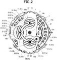
- FIG. 2 shows an example in which a solar panel is installed in a timepiece, and is a plan view showing a state in which the solar panel is disposed above the module and the date indicator.
- a support seat 25 (see FIG. 5A and FIG. 5B ) is disposed between the module 2 and the date indicator 21 and the solar panel 5 to prevent the solar panel 5 from contacting directly with the surfaces of the module 2 and the date indicator 21 and from being damaged by rubbing against each other.
- the solar panel 5 has substantially the same length as the diameter of the module 2 in the direction from twelve o'clock to six o'clock (hereinafter referred to as "longitudinal direction") when installed in the timepiece 100.
- the end portion in the protruding direction protruding perpendicular to the longitudinal direction in the surface toward nine o'clock in the timepiece is disposed substantially at the same position as the end portion of the module 2 on the nine o'clock side.
- the solar panel 5 is provided with a through hole 53a into which the hand shaft 19a is inserted at a position corresponding to the hand shaft 19a.
- a through hole 53b into which the hand shaft 19b is inserted is provided at a position corresponding to the hand shaft 19b provided in each of the inner dials 18.
- the solar panel 5 includes:
- FIG. 3 is a plan view of the solar panel of the embodiment.
- the solar panel 5 of the embodiment includes:
- Each of the solar cells 51a-51e includes a power generation area corresponding to the three power generators 6a-6c and a connection area corresponding to the connector 55.
- the solar cell 51e is a solar cell including:
- the number of solar cells 51 provided in the solar panel 5 is not limited to five and may be more or less.
- the number of power generators 6 provided in the solar panel 5 is not limited to three and may be more or less.
- the arrangement, shape, number, and the like of the power generator 6 are set in accordance with the arrangement, shape, number, and the like of the highly transparent area of an equipment in which the power generator 6 is installed (in the embodiment, the highly transparent areas Ar1-Ar3 of the dial 16).
- the power generator 6 having substantially the same area as that of the highly transparent area (in the embodiment, the highly transparent areas Ar1-Ar3 which is the openings 181 of the dial 16) generates power by receiving light to produce a voltage equivalent to 500Lx.
- a voltage sufficiently larger than the full charge voltage of the secondary battery is obtained.
- the power generator 6 having an area larger than that of the highly transparent area generates power by receiving light, power generation efficiency is reduced. For example, only a voltage of about 50Lx is obtained. It is difficult to exceed the full charge voltage of the secondary battery.
- the arrangement, shape, and the like of the power generator 6 matches with the arrangement, shape, and the like of the highly transparent area of an equipment in which the power generator is installed as much as possible.
- the highly transparent areas Ar1-Ar3, which is the opening 181 of the dial 16, and the power generators 6a-6c of the solar panel 5 are designed to have substantially the same arrangement and shape.
- the portion of the solar panel 5 where the solar cells 51a-51e and the connectors 55, 56 are not provided is a non-power generator 7 that does not contribute to power generation.
- the non-power generator 7 positions and fixes the solar panel 5 when the solar panel 5 is installed in an equipment.
- the bosses 22 are provided in the module 2 on the twelve and six o'clock sides of the analog timepiece as previously described.
- locking hollows 71 are formed in the non-power generator 7 of the solar panel 5 at positions corresponding to the bosses 22.
- the protrusion 23 protruding in the thickness direction of the timepiece is provided in the module 2 on the nine o'clock side of the analog timepiece.
- the cut-out 72 shaped to fit the protrusion 23 is formed in the non-power generator 7 of the solar panel 5 at a position corresponding to the protrusion 23.
- the solar panel 5 is disposed on the module 2 so that the bosses 22 fit into the locking hollows 71 and the protrusion 23 fits into the cut-out 72.
- the solar panel 5 is positioned in the rim of the module 2 on at least three points and is fixed to and supported by the module 2.
- the solar panel 5 is disposed to bridge over the date indicator 21 disposed above the module 2. Even if some warp or bend appears in the solar panel 5, it does not touch or interfere with the surface of the date indicator 21.
- the entire shape of the solar panel 5 is not limited to the example shown in the figure, and is appropriately set in accordance with the shape of an equipment (the timepiece 100 in the embodiment) in which the solar panel 5 is installed and with mounting status.
- the solar panel 5 is a sheet-like member that tends to cause warp or bend, it is preferable to have a minimal area required for fixation or the like to an equipment in which it is installed to realize stable installation.
- the solar cells 51a-51e are connected across the power generators 6a-6c through connection areas corresponding to the connectors 55.
- the solar cells 51a-51e are connected in series to serve as a single solar panel.
- the solar cell 51a is electrically connected to the adjacent solar cell 51b at the connector 56a.
- the solar cell 51b is electrically connected to the adjacent solar cell 51c at the connector 56b.
- the solar cell 51c is electrically connected to the adjacent solar cell 51d at the connector 56c.
- the solar cell 51d is electrically connected to the adjacent solar cell 51e at the connector 56d.
- the solar panel 5 includes:
- the terminal 52a on the side of the solar cell 51a is electrically connected to a positive electrode on a base plate (not shown) via the connector 24a.
- the terminal 52b on the side of the solar cell 51e is electrically connected to a negative electrode on the base plate (not shown) via the connector 24b (see FIG. 2 ).
- the five solar cells 51a-51e are connected in series and are electrically connected to the base plate.
- connectors 55, 56a-6d, terminals 52a, 52b, connectors 57a, 57b, and the like are not limited to the example shown in figures.
- the positions of electrical connections between the solar panel 5 and the base plate i.e., the positions of the two electrodes and the two connectors 24a, 24b on the base plate (not shown) are not particularly limited as long as the positions of the five solar cells 51a-51e are electrically connected to the base plate while being connected in series.
- it may be on the solar cell 51c or on the solar cell 51d.
- Each of the power generators 6a-6c is divided into five solar cells 51a-51e. This distributes effect of shadows casted on the power generators 6a-6c by the main hands 17a and the sub hands 17b, which are rotated above the power generators 6a-6c. It reduces effect of shadows of the hands on power generation efficiency as much as possible.
- the manner of dividing the solar cell 51 is not limited to the one exemplified herein.
- the solar cell 51 may be divided into various shapes to reduce effect of shadows of the hands on power generation efficiency.
- areas of the solar cell 51 in portions constituting the power generators 6a-6c are substantially the same so that output currents of the solar cells 51a-51e are substantially the same.
- FIGS. 4A, 4B, and C are cross-sectional views respectively along A-A line, B-B line, and C-C line in FIG. 3 .
- the power generator 6 in the solar panel 5 has a layer structure in which a back electrode 511 is formed on the base 510, and a semiconductor layer 512 and a transparent electrode 513 are piled thereon in this order.
- a seal (protective layer) 514 is provided to cover the entire layer structure.
- the non-power generator 7 is a portion that does not contribute to power generation and may be made smaller, depending on the shape of an equipment in which the solar panel 5 is installed.
- the base 510 is a flexible film-like base plate. Although there is no particular limitation on a material of the base 510, it is made of, for example, plastic or the like.
- the back electrode 511 is made of a material including a metallic material such as an aluminum conductor.
- a material of the back electrode 511 is not limited thereto.
- the semiconductor layer 512 is made of, for example, amorphous silicon (a-Si:H) or the like.
- the semiconductor layer 512 may be, for example, a pn junction type semiconductor in which a p-type semiconductor and an n-type semiconductor are joined.
- the back electrode 511 and the semiconductor layer 512 are piled on the base 510 by, for example, vapor deposition or the like.
- the method of providing the back electrode 511 and the semiconductor layer 512 on the base 510 is not limited thereto.
- the transparent electrode 513 is formed by, for example, crystallizing zinc oxide, indium oxide, tin oxide, or the like on a base plate made of glass or the like.
- a material and a method of forming the transparent electrode 513 is not limited thereto.
- the seal 514 is made of an insulating material.
- the thicknesses of the power generator 6 and other portions are adjusted by changing the amount of seal 514 (thickness of the seal 514) so that the thickness of the solar panel 5 is substantially the same throughout the whole.
- Materials and methods of forming of the seal 514 are not particularly limited.
- the through hole 53b is provided at the substantial center of each of the power generators 6a-6c in the solar panel 5.
- the hand shaft 19b of the hands (functional hand) 17b, which will be described later, is inserted into the through hole 53b.
- FIG. 4B shows a cross section (cross section along B-B line) of the portion where the through hole 53b is formed in the power generator 6a.
- the through hole 53b of the power generator 6a penetrates all of the base 510, the back electrode 511, the semiconductor layer 512, the transparent electrode 513, and the seal 514.
- the seal 514 is provided also on the inside of the through hole 53b.
- the seal 514 covers and insulates edges of the back electrode 511, the semiconductor layer 512, and the transparent electrode 513 so that they are not exposed inside the through hole 53b.
- FIG. 4C shows a cross section (cross section along C-C line) of a portion where the connector 55 is provided.
- the solar cells 51a, 51b may have a configuration like FIG. 4A
- the solar cells 51c-51e may have a configuration like FIG. 4C .
- a method of removing the transparent electrode 513 is not particularly limited. For example, processing with a laser or the like is performed. In the portion where the connector 55 is provided, not only the transparent electrode 513 but also the back electrode 511 and the semiconductor layer 512 may be removed.
- a specific material and a method of forming the insulating layer 515 are not particularly limited as long as it is a layer made of an insulating material.
- the conductor layer 516 may be made of a variety of conductive materials. A specific material and a forming method are not particularly limited.
- the connectors 56a-56d have a configuration like the one shown in FIG. 4C .
- the connectors 55 and the connectors 56a-56d both do not have a power generation function.
- the connector 55 connects the solar cells 51a-51e constituting the power generators 6a-6c with each other respectively for the solar cells 51a-51e.
- the connectors 56a-56d connect the solar cells 51a-51e with each other.
- a power generation amount in the connection areas corresponding to the connectors that connect the power generation areas corresponding to the power generators is smaller than a power generation amount in the power generation areas.
- the transparent electrode 513 is removed in the connectors 55 and the connectors 56a-56d to have the configuration shown in Fig. 4C .
- the connectors 55 and the connectors 56a-56d have a configuration that does not include a mechanism for generating power by receiving light.
- the dial 16 is made of a material that does not transmit light as in the embodiment, the portion other than the openings 181 is disposed under the dial 16 and is thereby shielded from light. Therefore, the portion below the dial 16 except the openings 181 does not function as a power generator even if the transparent electrode 513 is not removed.
- the transparent electrode 513 is removed in the solar cells 51c-51e to have the configuration shown in FIG. 4C . Thereby they have a configuration that does not include a mechanism for generating power by receiving light.
- portions other than the openings 181 are disposed under the dial 16.
- the transparent electrode 513 is not removed and has the configuration shown in FIG. 4A . Thereby the connectors 55 become the portion that "does not have the power generation function".
- the three power generators 6a, 6b, 6c provided on the solar panel 5 are respectively provided at positions corresponding to the inner dials 18.
- FIG. 5A is a cross-sectional view of a main portion around the inner dial 18.
- the opening 181 is formed at a portion in the dial 16 which corresponds to each inner dial 18.
- the power generators 6a, 6b, 6c of the solar panel 5 disposed below the dial 16 are exposed respectively from the openings 181 of the inner dials 18.
- various sheets having optical transparency may be put on the surfaces of the power generators 6a, 6b, 6c of the solar panel 5 which are exposed from the openings 181.
- a scale, time letters, or the like may be provided in the rim of the openings 181 of the inner dial 18 while nothing is put on the surfaces of the power generators 6a, 6b, 6c of the solar panel 5.
- a transparent cover 182 may be fitted into the opening 181 of each inner dial 18 by press fit or the like. This prevents direct exposure of the power generators 6a, 6b, 6c of the solar panel 5.
- the transparent cover 182 is made of a transparent resin, glass (e.g., sapphire glass), or the like having an optical transparency.
- a design of a small dial, time letters, a scale or the like may be added by printing, vapor deposition, or the like on front and back sides of the transparent cover 182 within a range in which they do not inhibit optical transparency.
- time letters or the like may be planted.
- a position-fixing member that positions and fixes the solar panel 5 may be provided on the dial 16.
- a boss 165 as the position-fixing member may protrude toward the solar panel 5 from the lower surface of the dial 16 while a locking portion 58 that receives the boss 165 is formed in the non-power generator 7 of the solar panel 5.
- the boss 165 on the dial 16 is fitted or adhesively fixed to the locking portion 58 on the solar panel 5.
- the solar panel 5 is fixed to the dial 16 and is integrated with the dial 16.
- FIG. 5C shows an example in which the locking portion 58 is a hollow, the locking portion 58 may be a hole penetrating in the thickness direction.
- the boss 166 as the position-fixing member on the dial 16 may include a boss top 167 having an outer diameter larger than an inner diameter of the locking portion 59 which is the hole.
- the boss top 167 of the boss 166 on the dial 16 is fitted to the locking portion 59 on the solar panel 5 by press-fitting or the like.
- the solar panel 5 is more reliably fixed to the dial 16 and is integrated with the dial 16.
- the solar panel 5 In a case in which the solar panel 5 is integrated with dial 16 as shown in FIG. 5C and FIG. 5D , the solar panel 5 does not need to be positioned or fixed on the side of the module 2. Therefore, the boss 22, the protrusion 23, or the like may not be provided in the module 2.
- the solar panel 5 is disposed on the module 2 with the date indicator 21 disposed on the upper surface.
- the solar panel 5 is disposed on the module 2 so that the bosses 22 fit into the locking hollows 71 and the protrusion 23 fits into the cut-out 72.
- the solar panel 5 is positioned and fixedly supported on at least three points in the rim of the module 2.
- the dial 16 is disposed above the solar panel 5.
- the highly transparent areas Ar1-Ar3, which are the openings 181 of the inner dial 18, are arranged to correspond to the power generators 6a-6c of the solar panel 5.
- the power generators 6a-6c are exposed from the openings 181.
- the power generators 6a-6c efficiently performs photovoltaic power generation, and the power obtained by the power generation is stored in the secondary battery.
- the secondary battery supplies power to operation units of the module 2, such as a motor, to drive the timepiece 100.
- the solar panel 5 includes the power generators 6a-6c and the connectors 55, 56.
- the power generators 6a-6c are constituted by the solar cells 51a-51e, and has the power generation function of generating power by receiving light.
- the connectors 55, 56 electrically connect the power generators 6a-6c and the solar cells 51a-51e, which constitute the power generators 6a-6c, with each other. Therefore, the entire solar panel 5 efficiently generates power without being affected by shadows of the hands 17a, 17b, and the like.
- the connectors 55, 56 have no generation function and therefore do not affect power generation efficiency of the power generators 6a-6c.
- the dial 16 includes:
- the highly transparent areas Ar1-Ar3 are provided to correspond to areas where the power generators 6a-6c are disposed in the solar panel 5.
- the power generators 6a-6c are brought together in the highly transparent areas Ar1-Ar3 of dial 16.
- a material of which the dial 16 is made can be selected more freely (material without optical transparency may also be selected) as compared to a case in which the solar panel 5 having the same shape as the entire dial 16 is disposed in the entire area under the dial 16. Installation of the solar panel 5, the overall timepiece configuration, a design, and the like can be more freely determined.
- the power generators 6a-6c and the connectors 55, 56 can be included, the connectors 55, 56 electrically connecting the power generators 6a-6c and the solar cells 51a-51e, which constitute the power generators 6a-6c, with each other.
- the connectors 55, 56 may not have a generation function so as not to affect power generation efficiency of the power generators 6a-6c.
- the highly transparent areas Ar1-Ar3 of the dial 16 are the openings 181 as cut-outs formed by cutting a portion of the dial 16.
- the power generators 6a-6c of the solar panel 5 are exposed from the opening 181.
- a material of which the dial 16 is made is not limited to a material that transmits light, such as polycarbonate.
- the dial 16 may be made of various materials including materials that do not transmit any light.
- the solar panel 5 is positioned and fixed to the dial 16 by the position-fixing members.
- the boss 22, the protrusion 23, and the like does not need be provided at positions corresponding to the shape or the like of the solar panel 5.
- the common module 2 can be applied to any design shape of the dial 16 and the solar panel 5 corresponding to the dial 16.
- the solar panel 5 is fixed to and supported by at least three points in the rim of the module 2 (in the embodiment, three points on the twelve o'clock side, the nine o'clock side, and the six o'clock side in the analog timepiece).
- the solar panel 5 is positioned to bridge over the date indicator 21 disposed above the module 2. Even if some warp or bend appears in the solar panel 5, it neither touches nor interferes with the surface of the date indicator 21.
- the hands 17a, 17b that rotate above the solar panel 5 are provided, the hands 17a, 17b are stopped in positions where they do not overlap the power generators 6a-6c in the sleep mode. Therefore, the solar panel 5 efficiently generates power without being affected by shadows of the hands 17a, 17b and the like.
- FIGS. 2 and 3 show an example in which the width of the solar cells 51a-51e in the portions constituting the power generators 6a-6c is the same as that in the portions constituting the connectors 55, 56.
- the connectors 55 and 56 (56a-56d) may be narrower than the portions constituting the power generators 6a-6c to have a shape of thin line.
- the connectors 55, 56 have the shape of thin line so that the connector 55 and the connectors 56a-56d are very narrow areas and therefore do not substantially serve as power generators, although the transparent electrode 513 is not removed and the connectors 55, 56 have a mechanism of generating power by receiving light like the power generators 6a-6c.
- the non-power generator 7 may be made smaller in accordance with a shape and the like of an equipment in which the solar panel 5 is installed. It makes the entire solar panel 5 smaller and lighter.
- the embodiment shows an example in which the solar panel 5 includes the three power generators 6a-6c.
- the number, shape, arrangement, and the like of the power generators 6 are not limited to the examples shown in the embodiment.
- the solar panel 5 may include just one power generator 6d.
- the power generator 6d in order to disperse effect of shadows casted on the power generator 6d by the main hands 17a and the sub hands 17b rotating above the power generator 6d, the power generator 6d preferably consists of divided solar cells 51 (e.g., five solar cells 51a-51e). This reduces effect of shadows of the hands on power generation efficiency as much as possible.
- the solar cells 51 preferably have substantially the same area so that output currents of the solar cells 51a-51e are substantially the same. It is similar to the case in which multiple power generators 6 are provided.
- the manner of dividing the solar cells 51 is not limited to the example described herein.
- the solar cells 51 may be divided into various shapes, such as a spiral or concentric circles, as long as effect of shadows of the hands on power generation efficiency is suppressed.
- the connectors 56a-56d connect the solar cells 51a-51e in series like the example shown in the embodiment.
- the terminal 52a on the side of the solar cell 51a which is connected to the solar cell 51a, is electrically connected to the positive electrode on the base plate via the connector 57a.
- the power generator 6d is provided corresponding to the highly transparent area of the dial 16, such as opening 181 corresponding to the face of inner dial 18.
- the positive and negative electrodes on the base plate may be provided at positions near the portion where the highly transparent area is disposed, rather than around the rim of the module 2.
- the connectors 24a, 24b connecting the positive and negative electrodes on the base plate and the terminals 52a, 52b of the solar panel 5 are not covered by the dial cover 163.
- the dial 16 is made of a material that does not transmit light, such as metal, a pressure mark or the like made by the connectors 24a, 24b is not visible from the display side and does not affect the appearance, although portions corresponding to the connectors 24a, 24b are not covered by the dial cover 163 or the like.
- the solar panel 5 is less likely to contact the date indicator 21 or the like. Some warp or bend may be acceptable. It allows a configuration in which a boss or the like is provided on the module so that the solar panel 5 is cantilevered on it.
- the solar panel 5 may be supported by the dial 16 according to the configuration shown in FIG, 5C and FIG, 5D , or the like.
- the embodiment shows an example in which the solar cells 51a-51e of the solar panel 5 are amorphous silicon-based solar panels that include the semiconductor layer 512 made of amorphous silicon (a-Si:H) and the like.
- configuration of the solar panel 5 is not limited thereto.
- gallium-based (thin-film crystalline) solar panel that generates power with a compound semiconductor made of two materials of gallium (Ga) and arsenic (As) may be applied.
- the solar panel 5 supplies power sufficient for the entire timepiece 100.
- the embodiment exemplifies a configuration in which the solar panel 5 is positioned and fixedly supported on three points on the sides of twelve o'clock, nine o'clock, and six o'clock in the analog timepiece.
- a configuration in which the solar panel 5 is positioned and fixedly supported is not limited to the shown example.
- the solar panel 5 may be fixed by being cantilevered on one or two points.
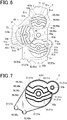
- the solar panel 5 has the power generator 6 (e.g., the power generator 6d in FIG. 7 ) having an area considerably smaller than the entire dial 16, such as the case of the aforementioned gallium-based (thin film crystalline) solar panel 5, the solar panel 5 may not be fixed bridging over the module 2 or the date indicator 21.
- a locking protrusion or the like may be provided around the inner dial having the opening 181, which is the highly transparent area, so that the solar panel 5 is cantilevered on one point.
- a hollow in which the solar panel 5 is disposed may be formed, for example, at a position corresponding to the solar panel 5 on the surface of the module 2 facing the dial 16.
- the solar panel 5 is accommodated in the hollow so that the surfaces of the solar panel 5 and the module 2 are substantially on the same plane.
- the solar panel 5 does not need to be floated between the module 2 and the dial 16 avoiding the date indicator 21 and the like. Therefore, there is no need to worry about warp and bend of the solar panel 5.
- the solar panel 5 is positioned only by being accommodated in the hollow, which eliminates the need for fixation members and assembly.
- the timepiece 100 may be provided with, for example, an antenna device that receives radio waves (e.g., a GPS antenna 9 shown in FIG. 8 ).
- an antenna device that receives radio waves (e.g., a GPS antenna 9 shown in FIG. 8 ).
- the GPS antenna 9 receives a GPS radio wave (i.e., radio wave including time information and the like transmitted from a GPS satellite) which is a microwave of a circularly polarized wave.
- a patch antenna is preferably used.
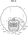
- FIG. 8 shows an example in which the GPS-antenna 9 includes a radiation electrode 91 having a substantially square shape.
- the solar panel 5 may be piled on the GPS antenna 9.
- a radiation pattern of the GPS antenna 9 which is a circularly polarized antenna spreads from an end (rim) of the radiation electrode 91.
- the radiation electrode 91 has a substantially square shape like the GPS antenna 9 shown in FIG. 8 , a radiation pattern spreading from each side (rim) greatly affects antenna characteristics (radio wave reception performance of an antenna) of the GPS antenna 9 as a circularly polarized antenna.
- the solar panel 5 is piled on the GPS antenna 9, it is preferable that the solar panel 5 is disposed substantially at the center of the radiation electrode 91 of the GPS antenna 9 as shown in FIG. 8 , so as not to overlap the end (rim) of the radiation electrode 91.
- a timepiece including the GPS antenna 9 that acquires time information and the solar panel 5 that receives light to generate power is compactly installed in a timepiece in a good condition without sacrificing either of antenna characteristics of the GPS antenna 9 and power generation efficiency of the solar panel 5.
- the embodiment shows an example in which the timepiece 100 is an analog timepiece that includes the three inner dials 18, the configuration of the display 15 of the timepiece 100 and the like are not limited to the examples shown in figures.
- the position and the number of the inner dials 18 are appropriately set according to a design and the like of the timepiece 100.
- the display 15 may be a digital display including a liquid crystal panel or the like.
- the display 15 may include both an analog display including the main hands 17a and a digital display including a liquid crystal panel.
- a material of the dial 16 is not limited to a material that does not transmit light.
- the dial 16 may be made of a resin material or the like which has a light transmittance of about 10% in a thick portion and has a light transmittance of about 30% in a thin portion.
- the thin portion is the highly transparent area while the thick portion is the less transparent area.
- the power generator 6 of the solar panel 5 is disposed in a portion corresponding to the thin portion.
- the embodiment illustrates an example in which the power generator 6 is exposed from the opening 181, but the highly transparent area is not limited to a portion where the power generator 6 is exposed.
- a light transmittance of about 30% is sufficient for the power generator 6 to generate power.
- the timepiece since the entire dial 16 and the small dial of the inner dial 18 are made of different materials, the timepiece has appearance of an excellent design.
- the embodiment shows an example in which the solar panel 5 is installed in the timepiece 100, but an equipment in which the solar panel 5 is installed is not limited to the timepiece 100.
- the solar panel 5 can be widely applied to equipments that operate on power generated by the solar panel 5 as a drive source, such as:
- the present invention is utilized in a solar panel and a display device and a timepiece having a solar panel.
Landscapes
- Physics & Mathematics (AREA)
- General Physics & Mathematics (AREA)
- Engineering & Computer Science (AREA)
- Power Engineering (AREA)
- Electromechanical Clocks (AREA)
- Electric Clocks (AREA)
- Photovoltaic Devices (AREA)
Abstract
Description
- The present invention relates to a solar panel, a display device and a timepiece.
- Conventionally, known timepieces include solar panels that receive light to generate power. In such a timepiece, a solar panel generates power to charge a secondary battery. It allows the battery to be used for a long time without replacement.
- For example, a watch or the like provided with a solar panel does not require battery replacement. It is a convenient watch that is easy to handle for users.
- However, since the solar panel is usually disposed below a dial, a material of which the dial is made is limited to plastics or the like having optical transparency to transmit light to the solar panel. It has been devised to express texture of metal by applying a coating or the like to this.
- The solar panel is a sheet in dark purple or the like. A solar panel visible through a dial is undesirable in design. Therefore, dark color coating may be applied to the dial such that an original color of the solar panel is not visible through the dial. However, it darkens the surface of the dial and makes it hard to be read. It also spoils the beauty.
- In view of this, for example, in
Patent Document 1 discloses a configuration in which a prism is provided on the lower surface of a transparent dial and a semitransparent reflector is provided on the lower side of the prism to maintain optical transparency for the solar panel while brightening the surface of the dial to keep beautiful appearance. - Patent Document 1:
JP 2011-174948 A - However, the configuration described in
Patent Document 1 requires complicated and delicate techniques, such as applying various surface processing such as painting on plastics or the like, to achieve beautiful appearance of the dial. Cost and effort for arranging the prism, etc. are required, which raises the overall product price. - Furthermore, even if plastics having optical transparency are coated or so, it is difficult to completely reproduce the same luxurious look as a dial made of various luxurious materials, such as actual metal and ceramics. It is a problem.
- The present invention has been made in view of the above circumstances. It is an object of the present invention to provide a solar panel, a display device, and a timepiece that efficiently generate power and realize beautiful appearance without any special processing or the like on a dial side when installed in a timepiece or the like.
- To achieve at least one of the abovementioned objects, according to an aspect of the present invention, a solar panel includes a solar cell, wherein the solar cell includes:
- power generation areas; and
- a connection area which connects the power generation areas and which generates a smaller amount of power than the power generation areas generate.
- The present invention achieves advantageous effect that power is efficiently generated and beautiful appearance is realized without performing special processing or the like on a dial side when installed in a timepiece or the like.
-
-
FIG. 1 is a front view of a timepiece according to an embodiment. -
FIG. 2 is a plan view illustrating an example in which a module, a solar panel, and the like are installed in the timepiece shown inFIG. 1 . -
FIG. 3 is a plan view of a solar panel according to the embodiment. -
Fig. 4A is a cross-sectional view along A-A line inFig. 3 . -
Fig. 4B is a cross-sectional view along B-B line inFig. 3 . -
Fig. 4C is a cross-sectional view along C-C line inFig. 3 . -
FIG. 5A is a cross-sectional view of an inner dial and the vicinity according to the embodiment. -
FIG. 5B is a cross-sectional view showing a configuration of a modification of the inner dial and the vicinity. -
FIG. 5C is a cross-sectional view showing a configuration of a modification of the inner dial and the vicinity. -
FIG. 5D is a cross-sectional view showing a modification of a portion surrounded by a dashed line inFIG. 5C . -
FIG. 6 is a plan view showing a modification of the solar panel. -
FIG. 7 is a plan view showing a modification of the solar panel. -
FIG. 8 is a plan view showing an example in which a modification of the solar panel is positioned on a GPS antenna. - An embodiment of a solar panel according to the present invention and a timepiece as a display device to which the solar panel is applied will be described with reference to
FIG. 1 to FIG. 5D . - Although various limitations which are technically preferred for carrying out the present invention are given to the embodiments described below, the scope of the present invention is not limited to the following embodiments and examples shown in figures.
-
FIG. 1 is a front view showing the timepiece as the display device according to the embodiment. - As shown in
FIG. 1 , thetimepiece 100 of the embodiment includes a case (hereinafter, referred to as "timepiece case 1" in the embodiment.) . Thetimepiece case 1 is made of, for example, metal such as stainless steel or titanium, ceramics, various synthetic resin, or the like. Materials of which thetimepiece case 1 is made are not limited to those exemplified here. - The
timepiece case 1 in the embodiment has a shape of a hollow short column. Aprotection cover 11 made of transparent glass or the like is attached to the front side of the timepiece 100 (the display side of the timepiece). A back cover (not shown) is attached to the back side of thetimepiece 100. - A
band connector 13 is provided at both upper and lower ends of thetimepiece case 1 inFIG. 1 , that is, at the end on the twelve o'clock side and at the end on the six o'clock side in the analog timepiece. A timepiece band (not shown) is attached to theband connector 13. - The
timepiece 100 is provided with an operation button 14 (crown in the embodiment) on a side or the like of thetimepiece case 1. - The timepiece 100 (display device) includes:
- a
display 15 including a dial 16 (display board); - a
module 2 disposed under thedial 16; and - a
solar panel 5 disposed between thedial 16 and themodule 2. - The
solar panel 5 includes a power generation function to generate power by receiving light as described later. Generated power obtained from photovoltaic generation by thesolar panel 5 is stored in a secondary battery. - A
display 15 including thedial 16, themodule 2, and thesolar panel 5 are accommodated in thetimepiece case 1. - The
module 2 includes: - a timepiece movement (not shown) which is constituted by a motor, a wheel train mechanism, and the like that rotate
main hands 17a andsub hands 17b described later; - a base plate (not shown) on which various electronic components and the like are mounted; and
- a secondary battery (not shown) that supplies power to functional units of the
timepiece 100. - A
hand shaft 19a to which themain hands 17a are attached and ahand shaft 19b to which the sub hands 17b are attached protrude from themodule 2. They penetrate thedial 16 and thesolar panel 5 to protrude above thedial 16 and thesolar panel 5. - As the
hand shaft 19a rotates about the axis, themain hands 17a are rotated above thedial 16 and thesolar panel 5. As thehand shaft 19b rotates about the axis, the sub hands 17b are rotated above thedial 16 and thesolar panel 5. - Rotation of the
main hands 17a and the sub hands 17b preferably stops in a sleep mode (power saving mode to suppress power consumption). At least themain hands 17a among the hands preferably stop at a position where it does not overlap the power generators 6 (6a-6c) of thesolar panel 5, which will be described later, in the sleep mode. - When the hands stop above the power generators 6 (6a-6c), the hands cast shadows on the power generators 6 (6a-6c). The shadows reduce power generation efficiency of the power generators 6 (6a-6c). Since the
main hands 17a among the hands are longer and wider than thesub hands 17b, they greatly influence power generation efficiency of the power generators 6 (6a-6c). Shifting stop positions of themain hands 17a in the sleep mode from positions above the power generators 6 (6a-6c) contribute to maintenance and improvement in power generation efficiency. - In the embodiment,
bosses 22 for positioning protrude from the upper rim of themodule 2 respectively on the twelve o'clock side and on the six o'clock side of the analog timepiece. Thebosses 22 are locked in lockinghollows 71 provided on the solar panel side, as will be described later. - A
protrusion 23 for positioning which protrudes in the thickness direction of the timepiece is formed on the upper rim of themodule 2 on the nine o'clock side of the analog timepiece. Theprotrusion 23 is locked in a cut-out 72 provided on the solar panel side, as will be described later. - A base plate (not shown) is mounted on the
module 2. For example, a spring connector 24 (24a, 24b; seeFIG. 2 ) is disposed at a position connecting a terminal (not shown) of the base plate for the solar panel and a terminal 52 (52a, 52b; seeFIGS. 2 and3 ) of thesolar panel 5. - The
timepiece 100 is provided with a ring-shapeddial cover 163 covering the rim of thedial 16. In the embodiment, as shown inFIG. 2 , the terminal 52 of thesolar panel 5 which is electrically connected to the terminal (not shown) of the base plate for the solar panel is disposed at the rim of themodule 2. Therefore, theconnector 24 is also disposed under thedial cover 163. - A
spring connector 24 pushes up thesolar panel 5 toward the display side from themodule 2 side. Therefore, if thedial 16 has optical transparency, a pressure mark due to theconnector 24 is visible through the display side of thedial 16. It spoils the beauty of thetimepiece 100. However, in a case in which theconnector 24 is positioned under thedial cover 163 as shown in the embodiment, thedial cover 163 covers the pressure mark even if the pressure mark appears due to theconnector 24. The beauty of thetimepiece 100 is not spoiled. - In the embodiment, the
dial 16 is made of metal or the like that does not transmit light, as will be described later. Therefore, even if theconnector 24 is disposed at a position away from thedial cover 163, the pressure mark caused by theconnector 24 is not visible through thedial 16 from the display side. Theconnector 24 and the terminal of the base plate for the solar panel and the terminal 52 ofsolar panel 5 which are connected by theconnector 24 can be arranged quite freely. - Because there is no need to hide the
connector 24 with thedial cover 163, thedial cover 163 can be designed and positioned regardless of a position of theconnector 24. Accordingly, for example, a configuration in which thedial cover 163 is made narrower to make thedial 16 visible in a wide range may be employed. - The
display 15 is provided under theprotection cover 11 in thetimepiece case 1 as shown inFig. 1 . - As shown in
FIG. 1 , thedisplay screen 15 in the embodiment is an analog display including adial 16,main hands 17a including an hour hand, a minute hand, and a second hand disposed above thedial 16, andsub hands 17b such as various function hands. - In the embodiment, the
dial 16 is made of a material that does not transmit light, such as metal and ceramics (not only a material that does not transmit light at all, but also a material that hardly transmits light). -
Time letters 161 as a guide of time indicated by themain hands 17a (hour hand, minute hand, second hand) are arranged in the rim of thedial 16 on the front side. - In the
timepiece 100 of the embodiment, as shown inFIG. 2 , a ring-shapeddate indicator 21 is disposed along the rim of themodule 2 between thesolar panel 5 and the module 2 (above themodule 2 and below the solar panel 5). Thedate indicator 21 is a rotating body that has numbers or the like indicating dates along the circumferential direction. At a position corresponding to four o'clock in the analog timepiece, awindow 162 is provided near the rim of thedial 16 to expose a date on thedate indicator 21 to the display side (seeFIG. 1 ). The arrangement and the like of thewindow 162 are not limited to the example shown in the figure. It is not essential to have thedate indicator 21. - In the embodiment, the
display 15 is provided with inner dials (small displays) 18 including functional hands which are the sub hands 17b and the like, in addition to the main display that displays time by the hour hand, the minute hand, and the second hand which are themain hands 17a. - The
inner dial 18 displays, for example, time in a different city or region (e.g., the current time in New York, etc.) which is different from the main time displayed with the hour hand, the minute hand, and the second hand (e.g., the current time in Tokyo when using thetimepiece 100 in Tokyo). - In the embodiment, around the
hand shaft 19a to which themain hand 17a is attached, the inner dials 18 are provided respectively on the twelve o'clock side, the nine o'clock side, and the six o'clock side of the analog timepiece. - Portions of the
dial 16 which correspond to faces of the inner dials 18 are theopenings 181 as cut-outs each formed by cutting a portion of thedial 16. - Around the
opening 181, a ring-shapedindicator ring 183 is provided to edge around theopening 181. Like thedial cover 163 in thetimepiece 100, theindicator ring 183 may have scale or the like attached along the circumferential direction by printing, vapor deposition, typesetting, or the like. It is not essential to provide theindicator ring 183 around theopening 181. Theindicator ring 183 may be omitted. - As previously mentioned, the
dial 16 in the embodiment is made of a material that does not transmit light. Theopenings 181 provided in the inner dials 18 are the only portions that transmits light. - That is, the
dial 16 includes highly transparent areas having high transparency and a less transparent area having lower optical transparency than the highly transparent areas have. In the embodiment, as shown inFIG. 1 , theopenings 181 provided in the threeinner dials 18 are the highly transparent areas Ar1-Ar3. The part of thedial 16 other than theopenings 181 is the less transparent area having lower optical transparency than the highly transparent areas Ar1-Ar3 have. - In the embodiment, as will be described later, the
solar panel 5 is provided with power generators 6 (in the embodiment, power generators 6a-6c) having a power generation function of generating power by receiving light. Theopenings 181 of the inner dials 18, which are the highly transparent areas Ar1-Ar3, are disposed to correspond to areas where thepower generators 6 are disposed in thesolar panel 5. - The part other than the
openings 181 is the less transparent area (in the embodiment, it has transmittance of substantially zero). Therefore, the portion of thesolar panel 5 disposed at the position corresponding the portion other than theopenings 181 is shielded from light. - A
solar panel 5 is disposed below thedial 16 and above themodule 2 and thedate indicator 21 disposed thereon. -
FIG. 2 shows an example in which a solar panel is installed in a timepiece, and is a plan view showing a state in which the solar panel is disposed above the module and the date indicator. - Preferably, a support seat 25 (see
FIG. 5A and FIG. 5B ) is disposed between themodule 2 and thedate indicator 21 and thesolar panel 5 to prevent thesolar panel 5 from contacting directly with the surfaces of themodule 2 and thedate indicator 21 and from being damaged by rubbing against each other. - As shown in
FIG. 2 , thesolar panel 5 has substantially the same length as the diameter of themodule 2 in the direction from twelve o'clock to six o'clock (hereinafter referred to as "longitudinal direction") when installed in thetimepiece 100. The end portion in the protruding direction protruding perpendicular to the longitudinal direction in the surface toward nine o'clock in the timepiece is disposed substantially at the same position as the end portion of themodule 2 on the nine o'clock side. - The
solar panel 5 is provided with a throughhole 53a into which thehand shaft 19a is inserted at a position corresponding to thehand shaft 19a. A throughhole 53b into which thehand shaft 19b is inserted is provided at a position corresponding to thehand shaft 19b provided in each of the inner dials 18. - The
solar panel 5 includes: - the
power generators 6 which consist ofsolar cells 51 and which has the power generation function of generating power by receiving light; - a
connector 55 that electrically connects thepower generators 6 with each other; and - a connector 56 that electrically connects the
solar cells 51, which constitute thepower generators 6, with each other. -
FIG. 3 is a plan view of the solar panel of the embodiment. - As shown in
FIGS. 2 and3 , thesolar panel 5 of the embodiment includes: - the three power generators 6a-6c that consist of five divided
solar cells 51a-51e; - the
connector 55 that electrically connects the power generators 6a-6c with each other; and - connectors 56a-56d that electrically connect the
solar cells 51a-51e, which constitute the power generators 6a-6c, with each other. - Each of the
solar cells 51a-51e includes a power generation area corresponding to the three power generators 6a-6c and a connection area corresponding to theconnector 55. - That is, the
solar cell 51e is a solar cell including: - a power generation area corresponding to the power generator 6a;
- a connection area corresponding to the
connector 55; - a power generation area corresponding to the power generator 6b;
- a connection area corresponding to the
connector 55; and - a power generation area corresponding to the power generator 6c.
- Other
solar cells 51a to 51d have the same configuration. - The number of
solar cells 51 provided in thesolar panel 5 is not limited to five and may be more or less. - The number of
power generators 6 provided in thesolar panel 5 is not limited to three and may be more or less. - The arrangement, shape, number, and the like of the
power generator 6 are set in accordance with the arrangement, shape, number, and the like of the highly transparent area of an equipment in which thepower generator 6 is installed (in the embodiment, the highly transparent areas Ar1-Ar3 of the dial 16). - For example, if a secondary cell can achieve a full charge by generating power in an environment of 500Lx, the
power generator 6 having substantially the same area as that of the highly transparent area (in the embodiment, the highly transparent areas Ar1-Ar3 which is theopenings 181 of the dial 16) generates power by receiving light to produce a voltage equivalent to 500Lx. Thus, a voltage sufficiently larger than the full charge voltage of the secondary battery is obtained. In contrast, if thepower generator 6 having an area larger than that of the highly transparent area generates power by receiving light, power generation efficiency is reduced. For example, only a voltage of about 50Lx is obtained. It is difficult to exceed the full charge voltage of the secondary battery. - Therefore, it is preferable that the arrangement, shape, and the like of the
power generator 6 matches with the arrangement, shape, and the like of the highly transparent area of an equipment in which the power generator is installed as much as possible. - In the embodiment, the highly transparent areas Ar1-Ar3, which is the
opening 181 of thedial 16, and the power generators 6a-6c of thesolar panel 5 are designed to have substantially the same arrangement and shape. - The power generators 6a-6c of the
solar panel 5, when installed in thetimepiece 100, is exposed from theopenings 181 of the dial, which are cut-outs, to sufficiently receive light to generate power. - The portion of the
solar panel 5 where thesolar cells 51a-51e and theconnectors 55, 56 are not provided is anon-power generator 7 that does not contribute to power generation. - The
non-power generator 7 positions and fixes thesolar panel 5 when thesolar panel 5 is installed in an equipment. - In the embodiment, the
bosses 22 are provided in themodule 2 on the twelve and six o'clock sides of the analog timepiece as previously described. Correspondingly, lockinghollows 71 are formed in thenon-power generator 7 of thesolar panel 5 at positions corresponding to thebosses 22. - The
protrusion 23 protruding in the thickness direction of the timepiece is provided in themodule 2 on the nine o'clock side of the analog timepiece. The cut-out 72 shaped to fit theprotrusion 23 is formed in thenon-power generator 7 of thesolar panel 5 at a position corresponding to theprotrusion 23. - The
solar panel 5 is disposed on themodule 2 so that thebosses 22 fit into the locking hollows 71 and theprotrusion 23 fits into the cut-out 72. Thus, thesolar panel 5 is positioned in the rim of themodule 2 on at least three points and is fixed to and supported by themodule 2. - According to this configuration, the
solar panel 5 is disposed to bridge over thedate indicator 21 disposed above themodule 2. Even if some warp or bend appears in thesolar panel 5, it does not touch or interfere with the surface of thedate indicator 21. - The entire shape of the
solar panel 5 is not limited to the example shown in the figure, and is appropriately set in accordance with the shape of an equipment (thetimepiece 100 in the embodiment) in which thesolar panel 5 is installed and with mounting status. - Reducing the size of the
non-power generator 7, which does not contribute to power generation, as much as possible makes the entiresolar panel 5 smaller and lighter. However, since thesolar panel 5 is a sheet-like member that tends to cause warp or bend, it is preferable to have a minimal area required for fixation or the like to an equipment in which it is installed to realize stable installation. - The embodiment includes:
- portions in which the
solar cells 51a-51e constitute the power generators 6a-6c; and - portions that serve as the
connectors 55 that connect the power generators 6a-6c with each other. - As shown in
FIG. 3 , thesolar cells 51a-51e are connected across the power generators 6a-6c through connection areas corresponding to theconnectors 55. - The
solar cells 51a-51e are connected in series to serve as a single solar panel. - Specifically, the
solar cell 51a is electrically connected to the adjacentsolar cell 51b at the connector 56a. Thesolar cell 51b is electrically connected to the adjacentsolar cell 51c at the connector 56b. Thesolar cell 51c is electrically connected to the adjacentsolar cell 51d at the connector 56c. Thesolar cell 51d is electrically connected to the adjacentsolar cell 51e at the connector 56d. - The
solar panel 5 includes: - a terminal 52a on the side of the
solar cell 51a which is connected to thesolar cell 51a via a connector 57a; and - a terminal 52b on the side of the
solar cell 51e which is connected to thesolar cell 51e via a connector 57b. - When the
solar panel 5 is installed in an equipment, the terminal 52a on the side of thesolar cell 51a is electrically connected to a positive electrode on a base plate (not shown) via the connector 24a. The terminal 52b on the side of thesolar cell 51e is electrically connected to a negative electrode on the base plate (not shown) via the connector 24b (seeFIG. 2 ). - Thus, the five
solar cells 51a-51e are connected in series and are electrically connected to the base plate. - The positions and shapes of the
connectors 55, 56a-6d, terminals 52a, 52b, connectors 57a, 57b, and the like are not limited to the example shown in figures. - The positions of electrical connections between the
solar panel 5 and the base plate, i.e., the positions of the two electrodes and the two connectors 24a, 24b on the base plate (not shown) are not particularly limited as long as the positions of the fivesolar cells 51a-51e are electrically connected to the base plate while being connected in series. For example, it may be on thesolar cell 51c or on thesolar cell 51d. - Each of the power generators 6a-6c is divided into five
solar cells 51a-51e. This distributes effect of shadows casted on the power generators 6a-6c by themain hands 17a and thesub hands 17b, which are rotated above the power generators 6a-6c. It reduces effect of shadows of the hands on power generation efficiency as much as possible. - The manner of dividing the
solar cell 51 is not limited to the one exemplified herein. Thesolar cell 51 may be divided into various shapes to reduce effect of shadows of the hands on power generation efficiency. - When output currents of the five
solar cells 51a-51e are different from each other, an output current value of the three power generator 6a-6c as a whole is reduced in accordance with thesolar cell 51 with the smallest output current value. - In order to increase power generation efficiency as much as possible, it is preferable that areas of the
solar cell 51 in portions constituting the power generators 6a-6c are substantially the same so that output currents of thesolar cells 51a-51e are substantially the same. -
FIGS. 4A, 4B, and C are cross-sectional views respectively along A-A line, B-B line, and C-C line inFIG. 3 . - As shown in
FIG. 4A , thepower generator 6 in thesolar panel 5 has a layer structure in which aback electrode 511 is formed on thebase 510, and asemiconductor layer 512 and atransparent electrode 513 are piled thereon in this order. A seal (protective layer) 514 is provided to cover the entire layer structure. - In the
non-power generator 7 outside thepower generator 6, only theseal 514 is provided on thebase 510. Thenon-power generator 7 is a portion that does not contribute to power generation and may be made smaller, depending on the shape of an equipment in which thesolar panel 5 is installed. - The
base 510 is a flexible film-like base plate. Although there is no particular limitation on a material of thebase 510, it is made of, for example, plastic or the like. - The
back electrode 511 is made of a material including a metallic material such as an aluminum conductor. A material of theback electrode 511 is not limited thereto. - The
semiconductor layer 512 is made of, for example, amorphous silicon (a-Si:H) or the like. Thesemiconductor layer 512 may be, for example, a pn junction type semiconductor in which a p-type semiconductor and an n-type semiconductor are joined. - The
back electrode 511 and thesemiconductor layer 512 are piled on thebase 510 by, for example, vapor deposition or the like. The method of providing theback electrode 511 and thesemiconductor layer 512 on thebase 510 is not limited thereto. - The
transparent electrode 513 is formed by, for example, crystallizing zinc oxide, indium oxide, tin oxide, or the like on a base plate made of glass or the like. A material and a method of forming thetransparent electrode 513 is not limited thereto. - The
seal 514 is made of an insulating material. The thicknesses of thepower generator 6 and other portions are adjusted by changing the amount of seal 514 (thickness of the seal 514) so that the thickness of thesolar panel 5 is substantially the same throughout the whole. Materials and methods of forming of theseal 514 are not particularly limited. - The through
hole 53b is provided at the substantial center of each of the power generators 6a-6c in thesolar panel 5. Thehand shaft 19b of the hands (functional hand) 17b, which will be described later, is inserted into the throughhole 53b.FIG. 4B shows a cross section (cross section along B-B line) of the portion where the throughhole 53b is formed in the power generator 6a. - As shown in
FIG. 4B , the throughhole 53b of the power generator 6a penetrates all of thebase 510, theback electrode 511, thesemiconductor layer 512, thetransparent electrode 513, and theseal 514. Theseal 514 is provided also on the inside of the throughhole 53b. Theseal 514 covers and insulates edges of theback electrode 511, thesemiconductor layer 512, and thetransparent electrode 513 so that they are not exposed inside the throughhole 53b. -
FIG. 4C shows a cross section (cross section along C-C line) of a portion where theconnector 55 is provided. - As shown
FIG. 4C , in the portion where theconnector 55 is provided (that is, a portion that "does not have a power generation function" described later), processing of removing thetransparent electrode 513 among the base 510, theback electrode 511, thesemiconductor layer 512, thetransparent electrode 513, and theseal 514 constituting the power generator 6a is performed. Aconductor layer 516 is disposed in place of thetransparent electrode 513. An insulatinglayer 515 is provided between thesemiconductor layer 512 and theconductor layer 516. In the portion where theconnector 55 is provided (i.e., the portion that "does not have the power generation function" described later), as shown in thesolar panel 5 ofFIG. 2 , thesolar cells FIG. 4A , and thesolar cells 51c-51e may have a configuration likeFIG. 4C . - A method of removing the
transparent electrode 513 is not particularly limited. For example, processing with a laser or the like is performed. In the portion where theconnector 55 is provided, not only thetransparent electrode 513 but also theback electrode 511 and thesemiconductor layer 512 may be removed. - A specific material and a method of forming the insulating
layer 515 are not particularly limited as long as it is a layer made of an insulating material. - The
conductor layer 516 may be made of a variety of conductive materials. A specific material and a forming method are not particularly limited. - Although not shown, the connectors 56a-56d have a configuration like the one shown in
FIG. 4C . - In the embodiment, the
connectors 55 and the connectors 56a-56d both do not have a power generation function. Theconnector 55 connects thesolar cells 51a-51e constituting the power generators 6a-6c with each other respectively for thesolar cells 51a-51e. The connectors 56a-56d connect thesolar cells 51a-51e with each other. - The phrase "does not have the power generation function" have meaning including:
- a case in which the
connectors 55 and the connectors 56a-56d do not have a mechanism for generating power by receiving light; - a case in which the
connectors 55 and the connectors 56a-56d are shielded from light so as not to receive light although these connectors have a mechanism for generating power by receiving light; and - a case in which the
connectors 55 and the connectors 56a-56d have very small areas so that they do not substantially function as power generators and do not affect power generation efficiency of the power generators. - Accordingly, in each of the solar cells, a power generation amount in the connection areas corresponding to the connectors that connect the power generation areas corresponding to the power generators is smaller than a power generation amount in the power generation areas.
- In the embodiment, the
transparent electrode 513 is removed in theconnectors 55 and the connectors 56a-56d to have the configuration shown inFig. 4C . Thereby theconnectors 55 and the connectors 56a-56d have a configuration that does not include a mechanism for generating power by receiving light. - If the
dial 16 is made of a material that does not transmit light as in the embodiment, the portion other than theopenings 181 is disposed under thedial 16 and is thereby shielded from light. Therefore, the portion below thedial 16 except theopenings 181 does not function as a power generator even if thetransparent electrode 513 is not removed. In theconnectors 55 shown in thesolar panel 5 ofFIG. 2 , thetransparent electrode 513 is removed in thesolar cells 51c-51e to have the configuration shown inFIG. 4C . Thereby they have a configuration that does not include a mechanism for generating power by receiving light. In thesolar cells openings 181 are disposed under thedial 16. Thetransparent electrode 513 is not removed and has the configuration shown inFIG. 4A . Thereby theconnectors 55 become the portion that "does not have the power generation function". - In the embodiment, the three power generators 6a, 6b, 6c provided on the
solar panel 5 are respectively provided at positions corresponding to the inner dials 18. -
FIG. 5A is a cross-sectional view of a main portion around theinner dial 18. - As shown in
FIG. 5A , theopening 181 is formed at a portion in thedial 16 which corresponds to eachinner dial 18. The power generators 6a, 6b, 6c of thesolar panel 5 disposed below thedial 16 are exposed respectively from theopenings 181 of the inner dials 18. - Although not shown in
FIG. 5A , various sheets having optical transparency (e.g., decorative sheets on which designs of various small dials are printed, sheets on which only time letters are printed, etc.) may be put on the surfaces of the power generators 6a, 6b, 6c of thesolar panel 5 which are exposed from theopenings 181. - A scale, time letters, or the like may be provided in the rim of the
openings 181 of theinner dial 18 while nothing is put on the surfaces of the power generators 6a, 6b, 6c of thesolar panel 5. - As shown in
FIG. 5B , atransparent cover 182 may be fitted into theopening 181 of eachinner dial 18 by press fit or the like. This prevents direct exposure of the power generators 6a, 6b, 6c of thesolar panel 5. Thetransparent cover 182 is made of a transparent resin, glass (e.g., sapphire glass), or the like having an optical transparency. In this case, a design of a small dial, time letters, a scale or the like may be added by printing, vapor deposition, or the like on front and back sides of thetransparent cover 182 within a range in which they do not inhibit optical transparency. Alternatively, time letters or the like may be planted. - A position-fixing member that positions and fixes the
solar panel 5 may be provided on thedial 16. - For example, as shown in
FIG. 5C , in the rim of theopening 181 of theinner dial 18 in thedial 16, aboss 165 as the position-fixing member may protrude toward thesolar panel 5 from the lower surface of thedial 16 while a lockingportion 58 that receives theboss 165 is formed in thenon-power generator 7 of thesolar panel 5. - In this case, the
boss 165 on thedial 16 is fitted or adhesively fixed to the lockingportion 58 on thesolar panel 5. Thus, thesolar panel 5 is fixed to thedial 16 and is integrated with thedial 16. - Although
FIG. 5C shows an example in which the lockingportion 58 is a hollow, the lockingportion 58 may be a hole penetrating in the thickness direction. - For example, as shown in
FIG. 5D , in a case in which the lockingportion 59 is a hole, theboss 166 as the position-fixing member on thedial 16 may include aboss top 167 having an outer diameter larger than an inner diameter of the lockingportion 59 which is the hole. - In this case, the
boss top 167 of theboss 166 on thedial 16 is fitted to the lockingportion 59 on thesolar panel 5 by press-fitting or the like. Thus, thesolar panel 5 is more reliably fixed to thedial 16 and is integrated with thedial 16. - In a case in which the
solar panel 5 is integrated withdial 16 as shown inFIG. 5C and FIG. 5D , thesolar panel 5 does not need to be positioned or fixed on the side of themodule 2. Therefore, theboss 22, theprotrusion 23, or the like may not be provided in themodule 2. - Next, operation of the
solar panel 5 and thetimepiece 100 in the embodiment will be described. - In the embodiment, the
solar panel 5 is disposed on themodule 2 with thedate indicator 21 disposed on the upper surface. Thesolar panel 5 is disposed on themodule 2 so that thebosses 22 fit into the locking hollows 71 and theprotrusion 23 fits into the cut-out 72. Thus, thesolar panel 5 is positioned and fixedly supported on at least three points in the rim of themodule 2. - The
dial 16 is disposed above thesolar panel 5. The highly transparent areas Ar1-Ar3, which are theopenings 181 of theinner dial 18, are arranged to correspond to the power generators 6a-6c of thesolar panel 5. The power generators 6a-6c are exposed from theopenings 181. - Therefore, when light enters from the
openings 181, the power generators 6a-6c efficiently performs photovoltaic power generation, and the power obtained by the power generation is stored in the secondary battery. The secondary battery supplies power to operation units of themodule 2, such as a motor, to drive thetimepiece 100. - According to the embodiment, the
solar panel 5 includes the power generators 6a-6c and theconnectors 55, 56. The power generators 6a-6c are constituted by thesolar cells 51a-51e, and has the power generation function of generating power by receiving light. Theconnectors 55, 56 electrically connect the power generators 6a-6c and thesolar cells 51a-51e, which constitute the power generators 6a-6c, with each other. Therefore, the entiresolar panel 5 efficiently generates power without being affected by shadows of thehands - The
connectors 55, 56 have no generation function and therefore do not affect power generation efficiency of the power generators 6a-6c. - In a case in which the
solar panel 5 of thetimepiece 100 of the embodiment is disposed between thedial 16 and themodule 2, thedial 16 includes: - highly transparent areas Ar1-Ar3 having high optical transparency; and
- a less transparent area having lower optical transparency than the highly transparent areas Ar1-Ar3 have.
- The highly transparent areas Ar1-Ar3 are provided to correspond to areas where the power generators 6a-6c are disposed in the
solar panel 5. - This increases power generation efficiency of the power generators 6a-6c.
- The power generators 6a-6c are brought together in the highly transparent areas Ar1-Ar3 of
dial 16. A material of which thedial 16 is made can be selected more freely (material without optical transparency may also be selected) as compared to a case in which thesolar panel 5 having the same shape as theentire dial 16 is disposed in the entire area under thedial 16. Installation of thesolar panel 5, the overall timepiece configuration, a design, and the like can be more freely determined. - Even in a case in which the
solar panel 5 is installed in thetimepiece 100, the power generators 6a-6c and theconnectors 55, 56 can be included, theconnectors 55, 56 electrically connecting the power generators 6a-6c and thesolar cells 51a-51e, which constitute the power generators 6a-6c, with each other. - Also in this case, the
connectors 55, 56 may not have a generation function so as not to affect power generation efficiency of the power generators 6a-6c. - In the embodiment, the highly transparent areas Ar1-Ar3 of the
dial 16 are theopenings 181 as cut-outs formed by cutting a portion of thedial 16. The power generators 6a-6c of thesolar panel 5 are exposed from theopening 181. - Therefore, even when the
dial 16 itself is made of a material that does not transmit light, such as metal or ceramics, sufficient power is generated. - As described above, in the embodiment, a material of which the
dial 16 is made is not limited to a material that transmits light, such as polycarbonate. Thedial 16 may be made of various materials including materials that do not transmit any light. - Therefore, it is possible to express luxurious look, to design freely, and the like without performing special processing, such as printing or vapor deposition, on the
dial 16. A timepiece with excellent design is realized. - In a case in which the
dial 16 is provided with bosses (theboss 165 inFIG. 5C and theboss 166 inFIG. 5D ) as the position-fixing members that position and fix thesolar panel 5, thesolar panel 5 is positioned and fixed to thedial 16 by the position-fixing members. - In this case, since positioning or fixing on the
module 2 is not required, theboss 22, theprotrusion 23, and the like does not need be provided at positions corresponding to the shape or the like of thesolar panel 5. Thecommon module 2 can be applied to any design shape of thedial 16 and thesolar panel 5 corresponding to thedial 16. - In the embodiment, the
solar panel 5 is fixed to and supported by at least three points in the rim of the module 2 (in the embodiment, three points on the twelve o'clock side, the nine o'clock side, and the six o'clock side in the analog timepiece). - According to this configuration, even in a case in which the ring-shaped
date indicator 21 along the rim of themodule 2 is disposed between thesolar panel 5 and themodule 2, thesolar panel 5 is positioned to bridge over thedate indicator 21 disposed above themodule 2. Even if some warp or bend appears in thesolar panel 5, it neither touches nor interferes with the surface of thedate indicator 21. - In a case in which the
hands solar panel 5 are provided, thehands solar panel 5 efficiently generates power without being affected by shadows of thehands - While embodiments of the present invention have been described above, the present invention is not limited to the embodiments. The present invention can be modified in various ways without departing from its scope.
- For example, the embodiments in
FIGS. 2 and3 show an example in which the width of thesolar cells 51a-51e in the portions constituting the power generators 6a-6c is the same as that in the portions constituting theconnectors 55, 56. However, for example, as shown inFIG. 6 , theconnectors 55 and 56 (56a-56d) may be narrower than the portions constituting the power generators 6a-6c to have a shape of thin line. - The
connectors 55, 56 have the shape of thin line so that theconnector 55 and the connectors 56a-56d are very narrow areas and therefore do not substantially serve as power generators, although thetransparent electrode 513 is not removed and theconnectors 55, 56 have a mechanism of generating power by receiving light like the power generators 6a-6c. - According to this, there is no need for processing such as removing the
transparent electrode 513 to replace it with theconductor layer 516. It makes manufacture easier. Since theconnector 55 and the connectors 56a-56d have the shape of thin line, an area of thenon-power generator 7 consisting of thebase 510 and theseal 514 increases. Thenon-power generator 7 may be made smaller in accordance with a shape and the like of an equipment in which thesolar panel 5 is installed. It makes the entiresolar panel 5 smaller and lighter. - The embodiment shows an example in which the
solar panel 5 includes the three power generators 6a-6c. However, the number, shape, arrangement, and the like of thepower generators 6 are not limited to the examples shown in the embodiment. - For example, as shown in
FIG. 7 , thesolar panel 5 may include just one power generator 6d. - Also in this case, in order to disperse effect of shadows casted on the power generator 6d by the
main hands 17a and the sub hands 17b rotating above the power generator 6d, the power generator 6d preferably consists of divided solar cells 51 (e.g., fivesolar cells 51a-51e). This reduces effect of shadows of the hands on power generation efficiency as much as possible. - In order to increase power generation efficiency as much as possible, the
solar cells 51 preferably have substantially the same area so that output currents of thesolar cells 51a-51e are substantially the same. It is similar to the case in whichmultiple power generators 6 are provided. - The manner of dividing the
solar cells 51 is not limited to the example described herein. Thesolar cells 51 may be divided into various shapes, such as a spiral or concentric circles, as long as effect of shadows of the hands on power generation efficiency is suppressed. - In a case in which the power generator 6d consists of the five
solar cells 51a-51e, the connectors 56a-56d connect thesolar cells 51a-51e in series like the example shown in the embodiment. - When the
solar panel 5 is installed in an equipment, the terminal 52a on the side of thesolar cell 51a, which is connected to thesolar cell 51a, is electrically connected to the positive electrode on the base plate via the connector 57a. The terminal 52b on the side of thesolar cell 51e, which is connected to thesolar cell 51e via the connector 57b, is electrically connected to the negative electrode on the base plate. - The power generator 6d is provided corresponding to the highly transparent area of the
dial 16, such asopening 181 corresponding to the face ofinner dial 18. In a case in which the highly transparent area is far from the rim of thedial 16, the positive and negative electrodes on the base plate may be provided at positions near the portion where the highly transparent area is disposed, rather than around the rim of themodule 2. - In this case, the connectors 24a, 24b connecting the positive and negative electrodes on the base plate and the terminals 52a, 52b of the
solar panel 5 are not covered by thedial cover 163. However, in a case in which thedial 16 is made of a material that does not transmit light, such as metal, a pressure mark or the like made by the connectors 24a, 24b is not visible from the display side and does not affect the appearance, although portions corresponding to the connectors 24a, 24b are not covered by thedial cover 163 or the like. - In a case in which the
solar panel 5 is far from the rim of themodule 2, thesolar panel 5 is less likely to contact thedate indicator 21 or the like. Some warp or bend may be acceptable. It allows a configuration in which a boss or the like is provided on the module so that thesolar panel 5 is cantilevered on it. - The
solar panel 5 may be supported by thedial 16 according to the configuration shown inFIG, 5C and FIG, 5D , or the like. - The embodiment shows an example in which the
solar cells 51a-51e of thesolar panel 5 are amorphous silicon-based solar panels that include thesemiconductor layer 512 made of amorphous silicon (a-Si:H) and the like. However, configuration of thesolar panel 5 is not limited thereto. - For example, a gallium-based (thin-film crystalline) solar panel that generates power with a compound semiconductor made of two materials of gallium (Ga) and arsenic (As) may be applied.
- In this case, nearly five times power generation efficiency of that of the amorphous silicon-based solar panel is realized. For example, if there is the
opening 181 for just one inner dial, thesolar panel 5 supplies power sufficient for theentire timepiece 100. - The embodiment exemplifies a configuration in which the
solar panel 5 is positioned and fixedly supported on three points on the sides of twelve o'clock, nine o'clock, and six o'clock in the analog timepiece. However, a configuration in which thesolar panel 5 is positioned and fixedly supported is not limited to the shown example. - For example, in a case in which the
solar panel 5 is even smaller and lighter than the example, interference to surrounding members due to warp or bend is reduced even if it is not fixedly supported on three points. In that case, thesolar panel 5 may be fixed by being cantilevered on one or two points. - In particular, in a case in which the
solar panel 5 has the power generator 6 (e.g., the power generator 6d inFIG. 7 ) having an area considerably smaller than theentire dial 16, such as the case of the aforementioned gallium-based (thin film crystalline)solar panel 5, thesolar panel 5 may not be fixed bridging over themodule 2 or thedate indicator 21. A locking protrusion or the like may be provided around the inner dial having theopening 181, which is the highly transparent area, so that thesolar panel 5 is cantilevered on one point. - In a case in which the small solar panel 5 (e.g., the
solar panel 5 inFIG. 7 ) as described above is installed in thetimepiece 100, a hollow in which thesolar panel 5 is disposed may be formed, for example, at a position corresponding to thesolar panel 5 on the surface of themodule 2 facing thedial 16. When installed, thesolar panel 5 is accommodated in the hollow so that the surfaces of thesolar panel 5 and themodule 2 are substantially on the same plane. - In this case, the
solar panel 5 does not need to be floated between themodule 2 and thedial 16 avoiding thedate indicator 21 and the like. Therefore, there is no need to worry about warp and bend of thesolar panel 5. Thesolar panel 5 is positioned only by being accommodated in the hollow, which eliminates the need for fixation members and assembly. - The
timepiece 100 may be provided with, for example, an antenna device that receives radio waves (e.g., aGPS antenna 9 shown inFIG. 8 ). - The
GPS antenna 9 receives a GPS radio wave (i.e., radio wave including time information and the like transmitted from a GPS satellite) which is a microwave of a circularly polarized wave. For example, a patch antenna is preferably used.FIG. 8 shows an example in which the GPS-antenna 9 includes aradiation electrode 91 having a substantially square shape. - As shown in
FIG. 8 , in a case in which theGPS antenna 9 is provided on themodule 2 and thesolar panel 5 is a small one with one power generator 6e like thesolar panel 5 shown inFIG. 7 , thesolar panel 5 may be piled on theGPS antenna 9. - A radiation pattern of the
GPS antenna 9 which is a circularly polarized antenna spreads from an end (rim) of theradiation electrode 91. - In a case in which the
radiation electrode 91 has a substantially square shape like theGPS antenna 9 shown inFIG. 8 , a radiation pattern spreading from each side (rim) greatly affects antenna characteristics (radio wave reception performance of an antenna) of theGPS antenna 9 as a circularly polarized antenna. - In order to improve the antenna characteristics of the
GPS antenna 9, it is essential not to inhibit the spread of the radiation pattern from each side of theradiation electrode 91. - In a case in which the
solar panel 5 is piled on theGPS antenna 9, it is preferable that thesolar panel 5 is disposed substantially at the center of theradiation electrode 91 of theGPS antenna 9 as shown inFIG. 8 , so as not to overlap the end (rim) of theradiation electrode 91. - With this configuration, a timepiece including the
GPS antenna 9 that acquires time information and thesolar panel 5 that receives light to generate power is compactly installed in a timepiece in a good condition without sacrificing either of antenna characteristics of theGPS antenna 9 and power generation efficiency of thesolar panel 5. - Although the embodiment shows an example in which the
timepiece 100 is an analog timepiece that includes the threeinner dials 18, the configuration of thedisplay 15 of thetimepiece 100 and the like are not limited to the examples shown in figures. - For example, the position and the number of the inner dials 18 are appropriately set according to a design and the like of the
timepiece 100. - The
display 15 may be a digital display including a liquid crystal panel or the like.
Thedisplay 15 may include both an analog display including themain hands 17a and a digital display including a liquid crystal panel. - The embodiment shows an example in which:
- the
dial 16 itself is made of a material that does not transmit light such as metal; - only the
openings 181 are the highly transparent areas (light transmittance of substantially 100%); and - the other part is the less transparent area (light transmittance of substantially 0%).
- However, a material of the
dial 16 is not limited to a material that does not transmit light. - For example, the
dial 16 may be made of a resin material or the like which has a light transmittance of about 10% in a thick portion and has a light transmittance of about 30% in a thin portion. - In this case, the thin portion is the highly transparent area while the thick portion is the less transparent area. The
power generator 6 of thesolar panel 5 is disposed in a portion corresponding to the thin portion. - The embodiment illustrates an example in which the
power generator 6 is exposed from theopening 181, but the highly transparent area is not limited to a portion where thepower generator 6 is exposed. - A light transmittance of about 30% is sufficient for the
power generator 6 to generate power. - It allows an example in which:
- the
dial 16 itself is made of a material that does not transmit light such as metal; - a small dial made of a resin material having a light transmittance of about 30% is fitted into the
opening 181 of theinner dial 18; and - the
power generator 6 of thesolar panel 5 is disposed in a portion corresponding to the small dial. - In this case, since the
entire dial 16 and the small dial of theinner dial 18 are made of different materials, the timepiece has appearance of an excellent design. - The embodiment shows an example in which the
solar panel 5 is installed in thetimepiece 100, but an equipment in which thesolar panel 5 is installed is not limited to thetimepiece 100. - The
solar panel 5 can be widely applied to equipments that operate on power generated by thesolar panel 5 as a drive source, such as: - biological information display devices such as pedometers, heart rate meters, and pulse meters; and
- display devices that display various kinds of information such as a travel distance, travel pace information, altitude information, and atmospheric pressure information.
- While several embodiments of the invention have been described above, the scope of the invention is not limited to the embodiments described above. The invention encompasses the scope of the invention as set forth in the claims and its equivalents.
- The present invention is utilized in a solar panel and a display device and a timepiece having a solar panel.
-
- 2
- module
- 5
- solar panel
- 6a-6c
- power generator
- 16
- dial
- 17a, 17
- hand
- 18
- inner dial
- 21
- date indicator
- 22
- boss
- 23
- protrusion
- 24
- connector
- 51a-51e
- solar cell
- 55
- connector
- 56a-56d
- connector
- 100
- timepiece
- 181
- opening
- Ar1-ar3
- highly transparent area
Claims (10)
- A solar panel comprising a solar cell, wherein the solar cell comprises:power generation areas; anda connection area which connects the power generation areas and which generates a smaller amount of power than the power generation areas generate.
- A solar panel comprising solar cells, wherein
each of the solar cells comprises:power generation areas; anda connection area which connects the power generation areas and which generates a smaller amount of power than the power generation areas generate, andpower generators are formed in the solar panel, each of the power generators consisting of the power generation areas of the solar cells disposed side by side. - The solar panel according to claim 1 or 2, wherein the connection area is narrower than the power generation area.
- A display device comprising:the solar panel according to claim 2; anda display board,whereinthe display board includes:highly transparent areas having high optical transparency; anda less transparent area having lower optical transparency than the highly transparent areas have,the highly transparent areas are disposed to correspond to areas where the power generators are disposed, andthe less transparent area is disposed to correspond to a area where the connection area is disposed.
- A timepiece comprising:the solar panel according to claim 2;a dial; anda module disposed under the dial,whereinthe display board includes:highly transparent areas having high optical transparency; anda less transparent area having lower optical transparency than the highly transparent areas have,the highly transparent areas are disposed to correspond to areas where the power generators are disposed, andthe less transparent area is disposed to correspond to a area where the connection area is disposed.
- The timepiece according to claim 5, wherein
the highly transparent area is a cut-out formed by cutting out a portion of the dial.
the power generator of the solar panel is exposed from the cut out. - The timepiece according to claim 6, wherein
the dial is made of a material that does not transmit light. - The timepiece according to any one of claims 5 to 7, wherein
the dial comprises a position-fixing member that positions and fixes the solar panel, and
the position-fixing member positions and fixes the solar panel on the dial. - The timepiece according to any one of claims 5 to 7, further comprising:a date indicator which is disposed between the solar panel and the module and which has a ring shape along a rim of the module,wherein the solar panel is fixed and supported on at least three points in the rim of the module.
- The timepiece according to any one of claims 5 to 9, further comprising:a hand rotated above the solar panel,wherein, in a sleep mode, the hand stops at a position where the hand does not overlap the power generator.
Applications Claiming Priority (2)
| Application Number | Priority Date | Filing Date | Title |
|---|---|---|---|
| JP2018046098A JP6763415B2 (en) | 2018-03-14 | 2018-03-14 | Solar panels, display devices and clocks |
| PCT/JP2019/001952 WO2019176293A1 (en) | 2018-03-14 | 2019-01-23 | Solar panel, display device, and watch |
Publications (2)
| Publication Number | Publication Date |
|---|---|
| EP3767398A1 true EP3767398A1 (en) | 2021-01-20 |
| EP3767398A4 EP3767398A4 (en) | 2021-12-01 |
Family
ID=67907099
Family Applications (1)
| Application Number | Title | Priority Date | Filing Date |
|---|---|---|---|
| EP19767151.4A Pending EP3767398A4 (en) | 2018-03-14 | 2019-01-23 | SOLAR PANEL, DISPLAY DEVICE AND CLOCK |
Country Status (5)
| Country | Link |
|---|---|
| US (2) | US12204286B2 (en) |
| EP (1) | EP3767398A4 (en) |
| JP (1) | JP6763415B2 (en) |
| CN (2) | CN114237013A (en) |
| WO (1) | WO2019176293A1 (en) |
Families Citing this family (9)
| Publication number | Priority date | Publication date | Assignee | Title |
|---|---|---|---|---|
| JP7400653B2 (en) * | 2020-07-27 | 2023-12-19 | Tdk株式会社 | Solar cells and electronic equipment equipped with them |
| JP7494655B2 (en) * | 2020-08-26 | 2024-06-04 | カシオ計算機株式会社 | Electronic clock |
| JP7613027B2 (en) * | 2020-09-08 | 2025-01-15 | セイコーエプソン株式会社 | Clock dial, method of manufacturing clock dial, and clock |
| JP7826633B2 (en) * | 2021-09-21 | 2026-03-10 | カシオ計算機株式会社 | Electronic devices and watches |
| JP7830927B2 (en) * | 2021-12-22 | 2026-03-17 | カシオ計算機株式会社 | Electronic equipment and methods for assembling electronic equipment |
| TWD226883S (en) * | 2022-03-21 | 2023-08-11 | 瑞士商奧米茄公司 瑞士 | Wristwatch |
| USD1061273S1 (en) * | 2022-05-11 | 2025-02-11 | Compagnie des Montres Longines, Francilion S.A. (Longines Watch Co. Francillon Ltd.) | Watch case |
| USD1062478S1 (en) * | 2023-03-08 | 2025-02-18 | Longines Watch Co. Francillon Ltd. | Watch |
| JP7754121B2 (en) * | 2023-03-24 | 2025-10-15 | カシオ計算機株式会社 | Manufacturing method of electronic watch and solar panel |
Family Cites Families (25)
| Publication number | Priority date | Publication date | Assignee | Title |
|---|---|---|---|---|
| US2282209A (en) * | 1939-08-02 | 1942-05-05 | Jr William M Pepper | Time interval indicating device |
| JPH07105510B2 (en) * | 1986-03-31 | 1995-11-13 | 京セラ株式会社 | Photovoltaic device manufacturing method |
| JPS62257771A (en) * | 1986-04-30 | 1987-11-10 | Seiko Epson Corp | Solar cell electrode structure |
| CN2105087U (en) * | 1991-10-04 | 1992-05-20 | 山东聊城手表厂 | Solar analog-type quartz accutron |
| JPH05150055A (en) * | 1991-11-27 | 1993-06-18 | Casio Comput Co Ltd | Electronic clock |
| US5912064A (en) * | 1995-04-07 | 1999-06-15 | Citizen Watch Co., Ltd. | Dial plate for solar battery powered watch |
| CN1182447C (en) * | 1996-03-08 | 2004-12-29 | 西铁城钟表股份有限公司 | Indicating plate for watches |
| JPH1073815A (en) * | 1996-06-19 | 1998-03-17 | Seiko Instr Inc | Reflective liquid crystal display |
| EP1126337A4 (en) * | 1998-11-26 | 2002-04-17 | Citizen Watch Co Ltd | Timepiece |
| WO2001071434A1 (en) * | 2000-03-21 | 2001-09-27 | Citizen Watch Co., Ltd. | Electronic unit |
| AU2001290684A1 (en) * | 2000-09-07 | 2002-03-22 | Timex Group B.V. | Solar powered watch with backlight capability |
| JP2002122682A (en) * | 2000-10-12 | 2002-04-26 | Citizen Watch Co Ltd | Electronic time piece |
| JP2003287579A (en) * | 2002-03-28 | 2003-10-10 | Kawaguchiko Seimitsu Co Ltd | Solar wrist watch |
| JP4926701B2 (en) * | 2004-04-13 | 2012-05-09 | シチズンホールディングス株式会社 | Electronic device with solar cell |
| US8243556B2 (en) * | 2005-02-09 | 2012-08-14 | Citizen Holdings Co., Ltd. | Display plate for solar cell apparatus and method of producing display plate for solar cell apparatus |
| JP4764043B2 (en) * | 2005-03-28 | 2011-08-31 | シチズンホールディングス株式会社 | Clock with rotation display function |
| US9280143B2 (en) * | 2011-03-25 | 2016-03-08 | Casio Computer Co., Ltd | Sensitivity adjustment device and radio wave communication device |
| JP5190136B2 (en) | 2011-06-13 | 2013-04-24 | シチズン時計河口湖株式会社 | Clock face with solar cell |
| JP6008181B2 (en) * | 2012-09-04 | 2016-10-19 | カシオ計算機株式会社 | Solar panels and watches |
| JP6048222B2 (en) * | 2013-03-04 | 2016-12-21 | カシオ計算機株式会社 | Solar panels and watches |
| EP2784607B1 (en) * | 2013-03-28 | 2017-01-18 | ETA SA Manufacture Horlogère Suisse | Watch comprising a flange |
| JP6310283B2 (en) * | 2014-03-12 | 2018-04-11 | シチズン時計株式会社 | Electronics |
| JP6740574B2 (en) * | 2015-07-22 | 2020-08-19 | セイコーエプソン株式会社 | clock |
| JP6638247B2 (en) * | 2015-08-07 | 2020-01-29 | セイコーエプソン株式会社 | Electronic clock |
| EP3460590B1 (en) * | 2017-09-26 | 2020-01-01 | Seiko Epson Corporation | Electronic timepiece |
-
2018
- 2018-03-14 JP JP2018046098A patent/JP6763415B2/en active Active
-
2019
- 2019-01-23 EP EP19767151.4A patent/EP3767398A4/en active Pending
- 2019-01-23 CN CN202210078927.1A patent/CN114237013A/en active Pending
- 2019-01-23 US US16/980,008 patent/US12204286B2/en active Active
- 2019-01-23 WO PCT/JP2019/001952 patent/WO2019176293A1/en not_active Ceased
- 2019-01-23 CN CN201980018982.8A patent/CN111919178B/en active Active
-
2024
- 2024-12-14 US US18/981,451 patent/US20250110449A1/en active Pending
Also Published As
| Publication number | Publication date |
|---|---|
| US20210255587A1 (en) | 2021-08-19 |
| JP2019158624A (en) | 2019-09-19 |
| US20250110449A1 (en) | 2025-04-03 |
| WO2019176293A1 (en) | 2019-09-19 |
| CN114237013A (en) | 2022-03-25 |
| CN111919178B (en) | 2022-01-14 |
| US12204286B2 (en) | 2025-01-21 |
| JP6763415B2 (en) | 2020-09-30 |
| CN111919178A (en) | 2020-11-10 |
| EP3767398A4 (en) | 2021-12-01 |
Similar Documents
| Publication | Publication Date | Title |
|---|---|---|
| US20250110449A1 (en) | Solar panel, display device, and timepiece | |
| CN106933088B (en) | Electronic device | |
| CN104950664B (en) | Electronic devices with solar panels | |
| JP6488548B2 (en) | Electronics | |
| JP6119683B2 (en) | Electronics | |
| US8804466B2 (en) | Electronic timepiece | |
| US10056516B2 (en) | Solar panel | |
| JP2016109522A (en) | Electronic watch | |
| JP6638247B2 (en) | Electronic clock | |
| WO2001071434A1 (en) | Electronic unit | |
| JP6428823B2 (en) | Electronics | |
| CN109557801B (en) | Electronic clock | |
| CN104932246A (en) | Electronic device and wristwatch | |
| JP7107089B2 (en) | electronic clock | |
| JP7225577B2 (en) | electronic clock | |
| JP6575588B2 (en) | Solar panels and electronics | |
| JP7131588B2 (en) | clock | |
| CN112213935A (en) | Clock and watch | |
| JP7078024B2 (en) | Solar panels, electronic devices and electronic clocks | |
| JP2019060721A (en) | Electronic clock | |
| JP6264987B2 (en) | Electronics | |
| JP2016194416A (en) | Satellite radio clock | |
| JP2019053071A (en) | Satellite wave clock | |
| JP2016169961A (en) | Satellite radio clock |
Legal Events
| Date | Code | Title | Description |
|---|---|---|---|
| STAA | Information on the status of an ep patent application or granted ep patent |
Free format text: STATUS: THE INTERNATIONAL PUBLICATION HAS BEEN MADE |
|
| PUAI | Public reference made under article 153(3) epc to a published international application that has entered the european phase |
Free format text: ORIGINAL CODE: 0009012 |
|
| STAA | Information on the status of an ep patent application or granted ep patent |
Free format text: STATUS: REQUEST FOR EXAMINATION WAS MADE |
|
| 17P | Request for examination filed |
Effective date: 20200914 |
|
| AK | Designated contracting states |
Kind code of ref document: A1 Designated state(s): AL AT BE BG CH CY CZ DE DK EE ES FI FR GB GR HR HU IE IS IT LI LT LU LV MC MK MT NL NO PL PT RO RS SE SI SK SM TR |
|
| AX | Request for extension of the european patent |
Extension state: BA ME |
|
| DAV | Request for validation of the european patent (deleted) | ||
| DAX | Request for extension of the european patent (deleted) | ||
| RIN1 | Information on inventor provided before grant (corrected) |
Inventor name: SAITO, YUTA |
|
| A4 | Supplementary search report drawn up and despatched |
Effective date: 20211102 |
|
| RIC1 | Information provided on ipc code assigned before grant |
Ipc: H02S 10/40 20140101ALI20211026BHEP Ipc: H01L 31/05 20140101ALI20211026BHEP Ipc: G04G 19/00 20060101ALI20211026BHEP Ipc: G04B 19/06 20060101ALI20211026BHEP Ipc: G04C 10/02 20060101AFI20211026BHEP |
|
| STAA | Information on the status of an ep patent application or granted ep patent |
Free format text: STATUS: EXAMINATION IS IN PROGRESS |
|
| 17Q | First examination report despatched |
Effective date: 20240104 |