EP3767241A1 - Magnetic field sensor with stray field immunity and large air gap performance - Google Patents
Magnetic field sensor with stray field immunity and large air gap performance Download PDFInfo
- Publication number
- EP3767241A1 EP3767241A1 EP20182174.1A EP20182174A EP3767241A1 EP 3767241 A1 EP3767241 A1 EP 3767241A1 EP 20182174 A EP20182174 A EP 20182174A EP 3767241 A1 EP3767241 A1 EP 3767241A1
- Authority
- EP
- European Patent Office
- Prior art keywords
- magnetic field
- sensing elements
- field sensing
- axis
- rotation
- Prior art date
- Legal status (The legal status is an assumption and is not a legal conclusion. Google has not performed a legal analysis and makes no representation as to the accuracy of the status listed.)
- Pending
Links
- 230000005291 magnetic effect Effects 0.000 title claims abstract description 168
- 230000036039 immunity Effects 0.000 title description 4
- 239000000758 substrate Substances 0.000 claims abstract description 37
- 230000035945 sensitivity Effects 0.000 claims description 24
- 238000010586 diagram Methods 0.000 description 6
- 238000001514 detection method Methods 0.000 description 5
- 239000004065 semiconductor Substances 0.000 description 5
- XUIMIQQOPSSXEZ-UHFFFAOYSA-N Silicon Chemical compound [Si] XUIMIQQOPSSXEZ-UHFFFAOYSA-N 0.000 description 3
- 230000005294 ferromagnetic effect Effects 0.000 description 3
- 229910052710 silicon Inorganic materials 0.000 description 3
- 239000010703 silicon Substances 0.000 description 3
- 230000005355 Hall effect Effects 0.000 description 2
- 230000009286 beneficial effect Effects 0.000 description 2
- 239000000919 ceramic Substances 0.000 description 2
- WPYVAWXEWQSOGY-UHFFFAOYSA-N indium antimonide Chemical compound [Sb]#[In] WPYVAWXEWQSOGY-UHFFFAOYSA-N 0.000 description 2
- 239000000463 material Substances 0.000 description 2
- JBRZTFJDHDCESZ-UHFFFAOYSA-N AsGa Chemical compound [As]#[Ga] JBRZTFJDHDCESZ-UHFFFAOYSA-N 0.000 description 1
- 230000001133 acceleration Effects 0.000 description 1
- 239000004020 conductor Substances 0.000 description 1
- -1 e.g. Chemical compound 0.000 description 1
- 229910052732 germanium Inorganic materials 0.000 description 1
- GNPVGFCGXDBREM-UHFFFAOYSA-N germanium atom Chemical compound [Ge] GNPVGFCGXDBREM-UHFFFAOYSA-N 0.000 description 1
- 150000002472 indium compounds Chemical class 0.000 description 1
- 230000002452 interceptive effect Effects 0.000 description 1
- 230000005381 magnetic domain Effects 0.000 description 1
- 229910052751 metal Inorganic materials 0.000 description 1
- 239000002184 metal Substances 0.000 description 1
- 230000007935 neutral effect Effects 0.000 description 1
- 230000007704 transition Effects 0.000 description 1
- 230000005641 tunneling Effects 0.000 description 1
Images


Classifications
-
- G—PHYSICS
- G01—MEASURING; TESTING
- G01R—MEASURING ELECTRIC VARIABLES; MEASURING MAGNETIC VARIABLES
- G01R33/00—Arrangements or instruments for measuring magnetic variables
- G01R33/02—Measuring direction or magnitude of magnetic fields or magnetic flux
- G01R33/06—Measuring direction or magnitude of magnetic fields or magnetic flux using galvano-magnetic devices
- G01R33/07—Hall effect devices
- G01R33/072—Constructional adaptation of the sensor to specific applications
-
- G—PHYSICS
- G01—MEASURING; TESTING
- G01R—MEASURING ELECTRIC VARIABLES; MEASURING MAGNETIC VARIABLES
- G01R33/00—Arrangements or instruments for measuring magnetic variables
- G01R33/02—Measuring direction or magnitude of magnetic fields or magnetic flux
- G01R33/06—Measuring direction or magnitude of magnetic fields or magnetic flux using galvano-magnetic devices
- G01R33/07—Hall effect devices
- G01R33/077—Vertical Hall-effect devices
-
- G—PHYSICS
- G01—MEASURING; TESTING
- G01D—MEASURING NOT SPECIALLY ADAPTED FOR A SPECIFIC VARIABLE; ARRANGEMENTS FOR MEASURING TWO OR MORE VARIABLES NOT COVERED IN A SINGLE OTHER SUBCLASS; TARIFF METERING APPARATUS; MEASURING OR TESTING NOT OTHERWISE PROVIDED FOR
- G01D3/00—Indicating or recording apparatus with provision for the special purposes referred to in the subgroups
- G01D3/028—Indicating or recording apparatus with provision for the special purposes referred to in the subgroups mitigating undesired influences, e.g. temperature, pressure
-
- G—PHYSICS
- G01—MEASURING; TESTING
- G01D—MEASURING NOT SPECIALLY ADAPTED FOR A SPECIFIC VARIABLE; ARRANGEMENTS FOR MEASURING TWO OR MORE VARIABLES NOT COVERED IN A SINGLE OTHER SUBCLASS; TARIFF METERING APPARATUS; MEASURING OR TESTING NOT OTHERWISE PROVIDED FOR
- G01D5/00—Mechanical means for transferring the output of a sensing member; Means for converting the output of a sensing member to another variable where the form or nature of the sensing member does not constrain the means for converting; Transducers not specially adapted for a specific variable
- G01D5/12—Mechanical means for transferring the output of a sensing member; Means for converting the output of a sensing member to another variable where the form or nature of the sensing member does not constrain the means for converting; Transducers not specially adapted for a specific variable using electric or magnetic means
- G01D5/14—Mechanical means for transferring the output of a sensing member; Means for converting the output of a sensing member to another variable where the form or nature of the sensing member does not constrain the means for converting; Transducers not specially adapted for a specific variable using electric or magnetic means influencing the magnitude of a current or voltage
- G01D5/142—Mechanical means for transferring the output of a sensing member; Means for converting the output of a sensing member to another variable where the form or nature of the sensing member does not constrain the means for converting; Transducers not specially adapted for a specific variable using electric or magnetic means influencing the magnitude of a current or voltage using Hall-effect devices
- G01D5/145—Mechanical means for transferring the output of a sensing member; Means for converting the output of a sensing member to another variable where the form or nature of the sensing member does not constrain the means for converting; Transducers not specially adapted for a specific variable using electric or magnetic means influencing the magnitude of a current or voltage using Hall-effect devices influenced by the relative movement between the Hall device and magnetic fields
-
- G—PHYSICS
- G01—MEASURING; TESTING
- G01R—MEASURING ELECTRIC VARIABLES; MEASURING MAGNETIC VARIABLES
- G01R15/00—Details of measuring arrangements of the types provided for in groups G01R17/00 - G01R29/00, G01R33/00 - G01R33/26 or G01R35/00
- G01R15/14—Adaptations providing voltage or current isolation, e.g. for high-voltage or high-current networks
- G01R15/20—Adaptations providing voltage or current isolation, e.g. for high-voltage or high-current networks using galvano-magnetic devices, e.g. Hall-effect devices, i.e. measuring a magnetic field via the interaction between a current and a magnetic field, e.g. magneto resistive or Hall effect devices
- G01R15/202—Adaptations providing voltage or current isolation, e.g. for high-voltage or high-current networks using galvano-magnetic devices, e.g. Hall-effect devices, i.e. measuring a magnetic field via the interaction between a current and a magnetic field, e.g. magneto resistive or Hall effect devices using Hall-effect devices
-
- G—PHYSICS
- G01—MEASURING; TESTING
- G01R—MEASURING ELECTRIC VARIABLES; MEASURING MAGNETIC VARIABLES
- G01R15/00—Details of measuring arrangements of the types provided for in groups G01R17/00 - G01R29/00, G01R33/00 - G01R33/26 or G01R35/00
- G01R15/14—Adaptations providing voltage or current isolation, e.g. for high-voltage or high-current networks
- G01R15/20—Adaptations providing voltage or current isolation, e.g. for high-voltage or high-current networks using galvano-magnetic devices, e.g. Hall-effect devices, i.e. measuring a magnetic field via the interaction between a current and a magnetic field, e.g. magneto resistive or Hall effect devices
- G01R15/205—Adaptations providing voltage or current isolation, e.g. for high-voltage or high-current networks using galvano-magnetic devices, e.g. Hall-effect devices, i.e. measuring a magnetic field via the interaction between a current and a magnetic field, e.g. magneto resistive or Hall effect devices using magneto-resistance devices, e.g. field plates
-
- G—PHYSICS
- G01—MEASURING; TESTING
- G01R—MEASURING ELECTRIC VARIABLES; MEASURING MAGNETIC VARIABLES
- G01R15/00—Details of measuring arrangements of the types provided for in groups G01R17/00 - G01R29/00, G01R33/00 - G01R33/26 or G01R35/00
- G01R15/14—Adaptations providing voltage or current isolation, e.g. for high-voltage or high-current networks
- G01R15/20—Adaptations providing voltage or current isolation, e.g. for high-voltage or high-current networks using galvano-magnetic devices, e.g. Hall-effect devices, i.e. measuring a magnetic field via the interaction between a current and a magnetic field, e.g. magneto resistive or Hall effect devices
- G01R15/207—Constructional details independent of the type of device used
-
- G—PHYSICS
- G01—MEASURING; TESTING
- G01R—MEASURING ELECTRIC VARIABLES; MEASURING MAGNETIC VARIABLES
- G01R33/00—Arrangements or instruments for measuring magnetic variables
- G01R33/02—Measuring direction or magnitude of magnetic fields or magnetic flux
- G01R33/06—Measuring direction or magnitude of magnetic fields or magnetic flux using galvano-magnetic devices
- G01R33/09—Magnetoresistive devices
- G01R33/091—Constructional adaptation of the sensor to specific applications
Definitions
- This patent relates to magnetic field sensors and, more particularly, to magnetic field sensors with stray field immunity and large air gaps between the magnetic target and the magnetic field sensor.
- Magnetic field sensors can be used in various types of devices to measure and monitor properties of systems in a wide variety of different applications.
- sensors have become common in products that rely on electronics in their operation, such as motor control systems and automobile control systems.
- motor control applications include detection of the position and/or rotation of a motor
- automotive applications include detection of ignition timing from a position or rotation of an engine crankshaft and/or camshaft, detection of wheel speed for anti-lock braking systems and four-wheel steering systems, detection of window positioning, and other applications.
- a target ring magnet may be placed at the end of a rotating shaft so that it rotates as the shaft rotates.
- a magnetic field sensor can be positioned within the magnetic field produced by the ring magnet to detect the rotation.
- the magnetic field sensor has reduced sensitivity or immunity to the external field so that the output signal produced by the magnetic field sensor can more accurately reflect detection of the target.
- Magnetic field sensors that can operate with increased air gap distances between the magnetic field sensor and the target magnet may be beneficial in certain applications.
- the present invention can provide a magnetic field sensor that can operate with increased air gap distances between the magnetic field sensor and a target.
- a system in accordance with an example useful for understanding an aspect of the present invention, includes a ring magnet having magnetic segments and configured to rotate about an axis of rotation, wherein adjacent segments have different magnetic polarities,
- the system can further include a substrate positioned so that a top surface of the substrate is substantially parallel to the axis of rotation and a center plane passing through the ring magnet and perpendicular to the axis of rotation of the ring magnet intersects the top surface at an intersection line.
- the system can further include four magnetic field sensing elements supported by the substrate and electrically coupled to form a first bridge circuit, wherein two of the four magnetic field sensing elements are positioned on one side of the intersection line and the other two of the four magnetic field sensing elements are positioned on the other side of the intersection line.
- a magnetic field sensor includes a substrate having a top surface; a first bridge circuit supported by the substrate comprising a first set of four magnetic field sensing elements; and a second bridge circuit supported by the substrate comprising a second set of four magnetic field sensing elements, wherein each of the magnetic field sensing elements each has an axis of maximum sensitivity and is positioned so that the respective axes of maximum sensitivity are substantially parallel to an axis of rotation of a target.
- a system in accordance with another example useful for understanding another aspect of the present invention, includes a ring magnet having magnetic segments and configured to rotate about an axis of rotation, wherein adjacent segments have different magnetic polarities; a substrate positioned so that a top surface of the substrate is substantially parallel to the axis of rotation and a center plane passing through the ring magnet and perpendicular to the axis of rotation of the ring magnet intersects the top surface at an intersection line; and means for detecting the ring magnet and producing an output signal representing a state of the ring magnet.
- magnetic field sensing element is used to describe a variety of electronic elements that can sense a magnetic field.
- the magnetic field sensing element can be, but is not limited to, a Hall Effect element, a magnetoresistance element, or a magnetotransistor.
- Hall Effect elements for example, a planar Hall element, a vertical Hall element, and a Circular Vertical Hall (CVH) element.
- magnetoresistance elements for example, a semiconductor magnetoresistance element such as Indium Antimonide (InSb), a giant magnetoresistance (GMR) element, an anisotropic magnetoresistance element (AMR), a tunneling magnetoresistance (TMR) element, and a magnetic tunnel junction (MTJ).
- the magnetic field sensing element may be a single element or, alternatively, may include two or more magnetic field sensing elements arranged in various configurations, e.g., a half bridge or full (Wheatstone) bridge.
- the magnetic field sensing element may be a device made of a type IV semiconductor material such as Silicon (Si) or Germanium (Ge), or a type III-V semiconductor material like Gallium-Arsenide (GaAs) or an Indium compound, e.g., Indium-Antimonide (InSb).
- a type IV semiconductor material such as Silicon (Si) or Germanium (Ge)
- a type III-V semiconductor material like Gallium-Arsenide (GaAs) or an Indium compound, e.g., Indium-Antimonide (InSb).
- some of the above-described magnetic field sensing elements tend to have an axis of maximum sensitivity parallel to a substrate that supports the magnetic field sensing element, and others of the above-described magnetic field sensing elements tend to have an axis of maximum sensitivity perpendicular to a substrate that supports the magnetic field sensing element.
- planar Hall elements tend to have axes of sensitivity perpendicular to a substrate
- metal based or metallic magnetoresistance elements e.g., GMR and TMR
- vertical Hall elements tend to have axes of sensitivity parallel to a substrate.
- magnetic field sensor is used to describe a circuit that uses a magnetic field sensing element, generally in combination with other circuits.
- Magnetic field sensors are used in a variety of applications, including, but not limited to, an angle sensor that senses an angle of a direction of a magnetic field, a current sensor that senses a magnetic field generated by a current carried by a current-carrying conductor, a magnetic switch that senses the proximity of a ferromagnetic object, a rotation detector that senses passing ferromagnetic articles, for example, magnetic domains of a ring magnet or a ferromagnetic target (e.g., gear teeth) where the magnetic field sensor is used in combination with a back-biased or other magnet, and a magnetic field sensor that senses a magnetic field density of a magnetic field.
- an angle sensor that senses an angle of a direction of a magnetic field
- a current sensor that senses a magnetic field generated by a current carried by a current-carrying conductor
- a magnetic switch that
- target and “magnetic target” are used to describe an object to be sensed or detected by a magnetic field sensor or magnetic field sensing element.
- FIG. 1 is a block diagram of a system 100 for detecting a magnetic target 102.
- System 100 includes a magnetic field sensor 104 to detect a magnetic field produced by target 102 and generate a signal 104a representing the detected field.
- Magnetic field sensor 104 may be coupled to a processing circuit 106.
- Processing circuit 106 may be a computer processor or other circuit that can receive signal 104a.
- magnetic field sensor 104 is an automotive magnetic field sensor associated with a vehicle's braking system and processing circuit 106 is an automotive computer that controls the braking system.
- Target 102 may be a ring magnet having a plurality of sections 108-122.
- Sections 108-122 may be magnetic sources having alternating polarities.
- the sections may be permanent magnets and the outer surface of section 108 may be polarized to magnetic north, the outer surface of section 110 may be magnetic south, etc.
- some of the sections 108-122 may be magnetically neutral and may not generate a magnetic field.
- magnetic field sensor 104 may detect a changing magnetic field due to the varying magnetic polarities of sections 108-122.
- magnetic field sensor 104 may detect the transition of the magnetic field (e.g. from north to south, etc.) due to the changing polarities.
- Ring magnet 102 may be positioned to have an axis of rotation 128 in a direction into or out of the page. Also, the shortest distance between magnetic field sensor 104 and target 102 may be defined by the outer surface 124 of target 102. This distance 126 may define the air gap between target 102 and magnetic field sensor 104.
- magnetic field sensor 200 may be the same as or similar to magnetic field sensor 104.
- Magnetic field sensor 200 may include a substrate 202 that supports a plurality of magnetic field sensing elements A, B, C, and D.
- Substrate 202 may be a semiconductor substrate such as silicon, a semiconducting ceramic, etc. In other embodiments, substrate 200 may be a printed circuit board substrate or the like.
- a "top" surface 206 of substrate 202 may form a plane that is substantially parallel to an axis of rotation 204 of the target 102, which can be the same as the axis of rotation 128.
- Magnetic field sensing elements A-D may be magnetoresistance ("MR") elements each having an axis of maximum sensitivity indicated by arrows A', B', C' and D'. As shown, magnetic field sensing elements A-D may be positioned so that their axes of maximum sensitivity are roughly parallel to an axis of rotation 204 of target 104, which can be the same as the axis of rotation 128.
- MR magnetoresistance
- intersection line 208 is the intersection of that plane and substrate 200. Intersection line 208 can be upon a the "center plane" of target 102.
- magnetic field sensing elements A and B are located on one side of the center plane of the target 102 and magnetic field sensing elements C and D are located on the other side of the center plane of the target 102.
- the distance between target and surface 206 (e.g. distance 126 in FIG. 1 ) may be about 1.7 mm or greater.
- magnetic field sensing elements A-D may be electrically connected to form a bridge circuit 210, with magnetic field sensing elements A and C arranged in series from power 212 to ground 214 and magnetic field sensing elements D and B arranged in series from power 212 to ground 214.
- Bridge circuit 210 may generate a differential output signal between nodes 216 and 218 that represents the magnetic field as detected by bridge circuit 210.
- a magnetic field sensor magnetic field sensor 300 may include a substrate 302 that supports a plurality of magnetic field sensing elements A, B, C, D, E, F, G, and H.
- Substrate 302 may be a semiconductor substrate such as silicon, a semiconducting ceramic, etc. In other embodiments, substrate 302 may be a printed circuit board substrate or the like.
- a "top" surface 306 of substrate 302 may form a plane that is substantially parallel to the axis of rotation 304 of the target.
- Magnetic field sensing elements A-H may be magnetoresistance ("MR") elements each having an axis of maximum sensitivity. Each axis of maximum sensitivity has a direction indicated by an arrow, such as arrow 306. Thus, as shown, magnetic field sensing elements A-H may be positioned so that their respective axes of maximum sensitivity are roughly parallel to the axis of rotation 304 of target 104.
- MR magnetoresistance
- Intersection line 308 may be defined as the intersection of the plane formed by surface 306 and the plane formed by the circumference of ring magnet 102. Accordingly, intersection line 308 is substantially perpendicular to the ring magnet's axis of rotation 304.
- Magnetic field sensing elements A, B, E, and F may be positioned on surface 306 one side of intersection line 308 and magnetic field sensing elements C, D, G, and H may be positioned on the other side of intersection line 306 so that ring magnet 102 is positioned in the center along intersection line 308.
- magnetic field sensing elements A-H may be electrically coupled to form two bridge circuits 310 and 312.
- Bridge circuit 310 may include magnetic field sensing elements A and C coupled in series between power and ground, and magnetic field sensing elements B and D coupled in series between power and ground.
- bridge circuit 312 may include magnetic field sensing elements E and G coupled in series between power and ground, and magnetic field sensing elements H and F coupled in series between power and ground.
- the magnetic field may affect the sensitivity of each of the magnetic field sensing elements A-H.
- the magnetic field produced by the target 102 may affect the free layer along the bias direction (perpendicular to the arrows, e.g., 306) of the MR elements A-H rather than the most sensitive direction of the of the MR elements A-H (parallel to the arrows e.g., 306).
- the magnetic field produced by the target may alter the resistance of the MR elements A-H by changing their sensitivity to an external field rather than by directly changing the direction of the MR elements' free layer.
- each of elements A, B, C, D experiences the same field along the bias. Elements A, B have the same field along the sensitive direction that is opposite to the field experienced by elements C, D. Vertical stray field (i.e., field along the direction of arrow 304) will affect elements A, B, C, and D in the same way because they have the same bias. Thus, such vertical stray field will not generate a signal at the output of the bridge 310.
- each of elements E, F, G, H experiences the same field along the bias. Elements E, F have the same field along the sensitive direction that is opposite to the field experienced by elements G, H.
- Bridge circuit 310 may produce a differential output signal 310a which may be the difference between the voltages at nodes 314 and 316.
- bridge 312 may produce a differential output signal 312a which may be the difference between the voltages at nodes 318 and 320.
- a difference circuit 322 receives output signals 310a and 312a and provides output signal 322a.
- Output signal 322a may be the difference between bridge output 310a and bridge output 312a.
- Output signal 322a may represent the magnetic field as detected by magnetic field sensing elements A-H and may be used to calculate angular position, rotational speed, rotational direction, acceleration, and other properties of target 102.
- a graph 400 includes waveforms 402.
- the horizontal axis represents rotation of target 102 and the vertical axis represents the voltage of output signal 322a.
- Each waveform in the group of waveforms 402 may represent output signal 322a as measured with varying air gaps between target 102 and magnetic field sensor 300.
- Legend 404 includes a list of different air gaps associated with different waveforms 402.
- magnetic field sensor 300 may operate with relatively high distortion through an air gap range of 0.5 mm or less to 2.2 mm or more, as shown by the group of waveforms 408.
- graph 500 illustrates the amplitude of signal 322a for various magnetic field sensors.
- the horizontal axis represents the air gap distance between target 102 and the magnetic field sensor and the vertical axis represents the peak-to-peak amplitude of output signal 322a in logarithmic units of millivolts.
- Waveforms 502 may represent the output voltage of signal 322a as measured for various physical arrangements of magnetic field sensing elements A-H. As shown, the various arrangements may provide a substantially 1/(air gap) outputs from about 1.7 mm airgap or less to 8 mm airgap or more.
- graph 600 illustrates the amplitude of signal 322a for various magnetic field sensors in the presence of a stray, external field interfering with the signal produced by the magnetic field sensor.
- the horizontal axis represents the air gap distance in millimeters between target 102 and the magnetic field sensor and the vertical axis represents the peak-to-peak amplitude in millivolts of the magnetic field sensor's output.
- Waveform 602 represents the response of magnetic field sensor 300 to a stray, external magnetic field.
- Waveform 604 represents the response of a magnetic field sensor of the prior art to the same stray, external magnetic field.
- magnetic field sensor 300 is less sensitive to the stray, external magnetic field across all airgap distances of about 2mm or higher.
- magnetic field sensing elements A-H may be arranged so that magnetic field sensor 300 may provide reduced sensitivity or immunity to the stray field with air gaps less than about 2 mm.
Abstract
Description
- This patent relates to magnetic field sensors and, more particularly, to magnetic field sensors with stray field immunity and large air gaps between the magnetic target and the magnetic field sensor.
- Magnetic field sensors can be used in various types of devices to measure and monitor properties of systems in a wide variety of different applications. For example, sensors have become common in products that rely on electronics in their operation, such as motor control systems and automobile control systems. Common examples of motor control applications include detection of the position and/or rotation of a motor and common examples of automotive applications include detection of ignition timing from a position or rotation of an engine crankshaft and/or camshaft, detection of wheel speed for anti-lock braking systems and four-wheel steering systems, detection of window positioning, and other applications.
- As an example, a target ring magnet may be placed at the end of a rotating shaft so that it rotates as the shaft rotates. A magnetic field sensor can be positioned within the magnetic field produced by the ring magnet to detect the rotation.
- Many sensors must operate in the presence of external, stray magnetic fields that can interfere with the operation of the magnetic field sensor. Thus, it is beneficial if the magnetic field sensor has reduced sensitivity or immunity to the external field so that the output signal produced by the magnetic field sensor can more accurately reflect detection of the target.
- Also, many magnetic field sensors must be placed near the target magnet. Magnetic field sensors that can operate with increased air gap distances between the magnetic field sensor and the target magnet may be beneficial in certain applications.
- The present invention can provide a magnetic field sensor that can operate with increased air gap distances between the magnetic field sensor and a target.
- In accordance with an example useful for understanding an aspect of the present invention, a system includes a ring magnet having magnetic segments and configured to rotate about an axis of rotation, wherein adjacent segments have different magnetic polarities, The system can further include a substrate positioned so that a top surface of the substrate is substantially parallel to the axis of rotation and a center plane passing through the ring magnet and perpendicular to the axis of rotation of the ring magnet intersects the top surface at an intersection line. The system can further include four magnetic field sensing elements supported by the substrate and electrically coupled to form a first bridge circuit, wherein two of the four magnetic field sensing elements are positioned on one side of the intersection line and the other two of the four magnetic field sensing elements are positioned on the other side of the intersection line.
- In accordance with another example useful for understanding another aspect of the present invention, a magnetic field sensor includes a substrate having a top surface; a first bridge circuit supported by the substrate comprising a first set of four magnetic field sensing elements; and a second bridge circuit supported by the substrate comprising a second set of four magnetic field sensing elements, wherein each of the magnetic field sensing elements each has an axis of maximum sensitivity and is positioned so that the respective axes of maximum sensitivity are substantially parallel to an axis of rotation of a target.
- In accordance with another example useful for understanding another aspect of the present invention, a system includes a ring magnet having magnetic segments and configured to rotate about an axis of rotation, wherein adjacent segments have different magnetic polarities; a substrate positioned so that a top surface of the substrate is substantially parallel to the axis of rotation and a center plane passing through the ring magnet and perpendicular to the axis of rotation of the ring magnet intersects the top surface at an intersection line; and means for detecting the ring magnet and producing an output signal representing a state of the ring magnet.
- The foregoing features may be more fully understood from the following description of the drawings. The drawings aid in explaining and understanding the disclosed technology. Since it is often impractical or impossible to illustrate and describe every possible embodiment, the provided figures depict one or more exemplary embodiments. Accordingly, the figures are not intended to limit the scope of the invention. Like numbers in the figures denote like elements.
-
FIG. 1 is a block diagram of a magnetic field sensor system and a ring magnet target. -
FIG. 2 is a layout diagram of a magnetic field sensor with magnetic field sensing elements. -
FIG. 2A is a circuit diagram of the magnetic field sensing elements ofFIG. 2 . -
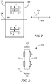
FIG. 3 is a layout diagram of another embodiment of a magnetic field sensor with magnetic field sensing elements. -
FIG. 3A is a circuit diagram of the magnetic field sensing elements ofFIG. 3 . -
FIG. 4 is a graph of magnetic field sensor output v. target rotation angle. -
FIG. 5 is a graph of magnetic field sensor output v. air gap distance between the magnetic field sensor and the target. -
FIG. 6 is a graph of magnetic field sensor output v. air gap distance between the magnetic field sensor and the target. - As used herein, the term "magnetic field sensing element" is used to describe a variety of electronic elements that can sense a magnetic field. The magnetic field sensing element can be, but is not limited to, a Hall Effect element, a magnetoresistance element, or a magnetotransistor. As is known, there are different types of Hall Effect elements, for example, a planar Hall element, a vertical Hall element, and a Circular Vertical Hall (CVH) element. As is also known, there are different types of magnetoresistance elements, for example, a semiconductor magnetoresistance element such as Indium Antimonide (InSb), a giant magnetoresistance (GMR) element, an anisotropic magnetoresistance element (AMR), a tunneling magnetoresistance (TMR) element, and a magnetic tunnel junction (MTJ). The magnetic field sensing element may be a single element or, alternatively, may include two or more magnetic field sensing elements arranged in various configurations, e.g., a half bridge or full (Wheatstone) bridge. Depending on the device type and other application requirements, the magnetic field sensing element may be a device made of a type IV semiconductor material such as Silicon (Si) or Germanium (Ge), or a type III-V semiconductor material like Gallium-Arsenide (GaAs) or an Indium compound, e.g., Indium-Antimonide (InSb).
- As is known, some of the above-described magnetic field sensing elements tend to have an axis of maximum sensitivity parallel to a substrate that supports the magnetic field sensing element, and others of the above-described magnetic field sensing elements tend to have an axis of maximum sensitivity perpendicular to a substrate that supports the magnetic field sensing element. In particular, planar Hall elements tend to have axes of sensitivity perpendicular to a substrate, while metal based or metallic magnetoresistance elements (e.g., GMR and TMR) and vertical Hall elements tend to have axes of sensitivity parallel to a substrate.
- As used herein, the term "magnetic field sensor" is used to describe a circuit that uses a magnetic field sensing element, generally in combination with other circuits. Magnetic field sensors are used in a variety of applications, including, but not limited to, an angle sensor that senses an angle of a direction of a magnetic field, a current sensor that senses a magnetic field generated by a current carried by a current-carrying conductor, a magnetic switch that senses the proximity of a ferromagnetic object, a rotation detector that senses passing ferromagnetic articles, for example, magnetic domains of a ring magnet or a ferromagnetic target (e.g., gear teeth) where the magnetic field sensor is used in combination with a back-biased or other magnet, and a magnetic field sensor that senses a magnetic field density of a magnetic field.
- As used herein, the terms "target" and "magnetic target" are used to describe an object to be sensed or detected by a magnetic field sensor or magnetic field sensing element.
-
FIG. 1 is a block diagram of asystem 100 for detecting amagnetic target 102.System 100 includes amagnetic field sensor 104 to detect a magnetic field produced bytarget 102 and generate asignal 104a representing the detected field.Magnetic field sensor 104 may be coupled to aprocessing circuit 106.Processing circuit 106 may be a computer processor or other circuit that can receivesignal 104a. In one example,magnetic field sensor 104 is an automotive magnetic field sensor associated with a vehicle's braking system andprocessing circuit 106 is an automotive computer that controls the braking system. -
Target 102 may be a ring magnet having a plurality of sections 108-122. Sections 108-122 may be magnetic sources having alternating polarities. For example, the sections may be permanent magnets and the outer surface ofsection 108 may be polarized to magnetic north, the outer surface ofsection 110 may be magnetic south, etc. In other embodiments, some of the sections 108-122 may be magnetically neutral and may not generate a magnetic field. In either case, astarget 102 rotates,magnetic field sensor 104 may detect a changing magnetic field due to the varying magnetic polarities of sections 108-122. Also,magnetic field sensor 104 may detect the transition of the magnetic field (e.g. from north to south, etc.) due to the changing polarities. -
Ring magnet 102 may be positioned to have an axis ofrotation 128 in a direction into or out of the page. Also, the shortest distance betweenmagnetic field sensor 104 andtarget 102 may be defined by theouter surface 124 oftarget 102. Thisdistance 126 may define the air gap betweentarget 102 andmagnetic field sensor 104. - Referring to
FIG. 2 ,magnetic field sensor 200 may be the same as or similar tomagnetic field sensor 104.Magnetic field sensor 200 may include asubstrate 202 that supports a plurality of magnetic field sensing elements A, B, C, andD. Substrate 202 may be a semiconductor substrate such as silicon, a semiconducting ceramic, etc. In other embodiments,substrate 200 may be a printed circuit board substrate or the like. A "top"surface 206 ofsubstrate 202 may form a plane that is substantially parallel to an axis ofrotation 204 of thetarget 102, which can be the same as the axis ofrotation 128. - Magnetic field sensing elements A-D may be magnetoresistance ("MR") elements each having an axis of maximum sensitivity indicated by arrows A', B', C' and D'. As shown, magnetic field sensing elements A-D may be positioned so that their axes of maximum sensitivity are roughly parallel to an axis of
rotation 204 oftarget 104, which can be the same as the axis ofrotation 128. - The circumference of
ring magnet 102 defines a plane. In an embodiment,intersection line 208 is the intersection of that plane andsubstrate 200.Intersection line 208 can be upon a the "center plane" oftarget 102. Thus, magnetic field sensing elements A and B are located on one side of the center plane of thetarget 102 and magnetic field sensing elements C and D are located on the other side of the center plane of thetarget 102. The distance between target and surface 206 (e.g. distance 126 inFIG. 1 ) may be about 1.7 mm or greater. - Referring to
FIG. 2A , magnetic field sensing elements A-D may be electrically connected to form abridge circuit 210, with magnetic field sensing elements A and C arranged in series frompower 212 toground 214 and magnetic field sensing elements D and B arranged in series frompower 212 toground 214.Bridge circuit 210 may generate a differential output signal betweennodes bridge circuit 210. - Referring to
FIG. 3 , a magnetic field sensormagnetic field sensor 300 may include asubstrate 302 that supports a plurality of magnetic field sensing elements A, B, C, D, E, F, G, andH. Substrate 302 may be a semiconductor substrate such as silicon, a semiconducting ceramic, etc. In other embodiments,substrate 302 may be a printed circuit board substrate or the like. A "top"surface 306 ofsubstrate 302 may form a plane that is substantially parallel to the axis ofrotation 304 of the target. - Magnetic field sensing elements A-H may be magnetoresistance ("MR") elements each having an axis of maximum sensitivity. Each axis of maximum sensitivity has a direction indicated by an arrow, such as
arrow 306. Thus, as shown, magnetic field sensing elements A-H may be positioned so that their respective axes of maximum sensitivity are roughly parallel to the axis ofrotation 304 oftarget 104. -
Intersection line 308 may be defined as the intersection of the plane formed bysurface 306 and the plane formed by the circumference ofring magnet 102. Accordingly,intersection line 308 is substantially perpendicular to the ring magnet's axis ofrotation 304. - Magnetic field sensing elements A, B, E, and F may be positioned on
surface 306 one side ofintersection line 308 and magnetic field sensing elements C, D, G, and H may be positioned on the other side ofintersection line 306 so thatring magnet 102 is positioned in the center alongintersection line 308. - Referring to
FIG. 3A , magnetic field sensing elements A-H may be electrically coupled to form twobridge circuits Bridge circuit 310 may include magnetic field sensing elements A and C coupled in series between power and ground, and magnetic field sensing elements B and D coupled in series between power and ground. Similarly,bridge circuit 312 may include magnetic field sensing elements E and G coupled in series between power and ground, and magnetic field sensing elements H and F coupled in series between power and ground. - In operation, as ring magnet (target) 102 rotates, the magnetic field may affect the sensitivity of each of the magnetic field sensing elements A-H. For example, because the axes of maximum sensitivity of the magnetic field sensing elements are parallel to the ring magnet's axis of rotation (128, 204, or 304), and thus perpendicular to the direction of rotation (205 or 305) of the
target 102, the magnetic field produced by thetarget 102 may affect the free layer along the bias direction (perpendicular to the arrows, e.g., 306) of the MR elements A-H rather than the most sensitive direction of the of the MR elements A-H (parallel to the arrows e.g., 306). By affecting the bias layer, the magnetic field produced by the target may alter the resistance of the MR elements A-H by changing their sensitivity to an external field rather than by directly changing the direction of the MR elements' free layer. - Considering
bridge 310 for example, each of elements A, B, C, D experiences the same field along the bias. Elements A, B have the same field along the sensitive direction that is opposite to the field experienced by elements C, D. Vertical stray field (i.e., field along the direction of arrow 304) will affect elements A, B, C, and D in the same way because they have the same bias. Thus, such vertical stray field will not generate a signal at the output of thebridge 310. Similarly, forbridge 312, each of elements E, F, G, H experiences the same field along the bias. Elements E, F have the same field along the sensitive direction that is opposite to the field experienced by elements G, H. Vertical stray field (i.e., field along the direction of arrow 304) will affect elements E, F, G, H in the same way because they have the same bias. Thus, such vertical stray field will not generate a signal at the output of thebridge 312. However, horizontal stray field (i.e., field along the direction of arrow 305) will affect bridge 310 differently than it affectsbridge 312. In particular, one bridge will lose sensitivity while the other may gain some sensitivity. Thus, once the signals from thebridges output signal 322a will be substantially insensitive to the stray field. -
Bridge circuit 310 may produce adifferential output signal 310a which may be the difference between the voltages atnodes bridge 312 may produce adifferential output signal 312a which may be the difference between the voltages atnodes difference circuit 322 receivesoutput signals output signal 322a.Output signal 322a may be the difference betweenbridge output 310a andbridge output 312a.Output signal 322a may represent the magnetic field as detected by magnetic field sensing elements A-H and may be used to calculate angular position, rotational speed, rotational direction, acceleration, and other properties oftarget 102. - Referring to
FIG. 4 , agraph 400 includeswaveforms 402. The horizontal axis represents rotation oftarget 102 and the vertical axis represents the voltage ofoutput signal 322a. Each waveform in the group ofwaveforms 402 may representoutput signal 322a as measured with varying air gaps betweentarget 102 andmagnetic field sensor 300.Legend 404 includes a list of different air gaps associated withdifferent waveforms 402. - In certain embodiments,
magnetic field sensor 300 may operate with relatively high distortion through an air gap range of 0.5 mm or less to 2.2 mm or more, as shown by the group of waveforms 408. - Referring to
FIG. 5 ,graph 500 illustrates the amplitude ofsignal 322a for various magnetic field sensors. The horizontal axis represents the air gap distance betweentarget 102 and the magnetic field sensor and the vertical axis represents the peak-to-peak amplitude ofoutput signal 322a in logarithmic units of millivolts.Waveforms 502 may represent the output voltage ofsignal 322a as measured for various physical arrangements of magnetic field sensing elements A-H. As shown, the various arrangements may provide a substantially 1/(air gap) outputs from about 1.7 mm airgap or less to 8 mm airgap or more. - Referring to
FIG. 6 ,graph 600 illustrates the amplitude ofsignal 322a for various magnetic field sensors in the presence of a stray, external field interfering with the signal produced by the magnetic field sensor. The horizontal axis represents the air gap distance in millimeters betweentarget 102 and the magnetic field sensor and the vertical axis represents the peak-to-peak amplitude in millivolts of the magnetic field sensor's output. -
Waveform 602 represents the response ofmagnetic field sensor 300 to a stray, external magnetic field.Waveform 604 represents the response of a magnetic field sensor of the prior art to the same stray, external magnetic field. As shown,magnetic field sensor 300 is less sensitive to the stray, external magnetic field across all airgap distances of about 2mm or higher. In other embodiments, magnetic field sensing elements A-H may be arranged so thatmagnetic field sensor 300 may provide reduced sensitivity or immunity to the stray field with air gaps less than about 2 mm. - Various embodiments are described in this patent. However, the scope of the patent should not be limited to the described embodiments, but rather should be limited only by the spirit and scope of the following claims. All references cited in this patent are incorporated by reference in their entirety.
Claims (19)
- A system comprising:a ring magnet having magnetic segments and configured to rotate about an axis of rotation, wherein adjacent segments have different magnetic polarities;a substrate positioned so that a top surface of the substrate is substantially parallel to the axis of rotation and a center plane passing through the ring magnet and perpendicular to the axis of rotation of the ring magnet intersects the top surface at an intersection line; andfour magnetic field sensing elements supported by the substrate and electrically coupled to form a first bridge circuit, wherein two of the four magnetic field sensing elements are positioned on one side of the intersection line and the other two of the four magnetic field sensing elements are positioned on the other side of the intersection line.
- The system of claim 1 wherein each of the four magnetic field sensing elements has an axis of maximum sensitivity and each magnetic field sensing element is arranged so that each axis of sensitivity is substantially parallel to the axis of rotation.
- The system of claim 1 wherein the four magnetic field sensing elements are magnetoresistance elements.
- The system of claim 1 wherein the four magnetic field sensing elements are arranged along a line that is substantially parallel to the axis of rotation.
- The system of claim 1 wherein the ring magnet is positioned to create an air gap between the ring magnet and the substrate.
- The system of claim 5 wherein the air gap is about 1.7 mm or greater.
- The system of claim 1 further comprising four additional magnetic field sensing elements electrically coupled to form a second bridge circuit.
- The system of claim 7 wherein two of the four additional magnetic field sensing elements are positioned on one side of the intersection line and the other two of the four additional magnetic field sensing elements are positioned on the other side of the intersection line.
- The system of claim 7 wherein each of the four additional magnetic field sensing elements has an axis of maximum sensitivity and each of the four additional magnetic field sensing elements is arranged so that each axis of sensitivity is substantially parallel to the axis of rotation.
- The system of claim 7 wherein the four additional magnetic field sensing elements are magnetoresistance elements.
- The system of claim 7 wherein the four additional magnetic field sensing elements are arranged along a line that is substantially parallel to the axis of rotation.
- A magnetic field sensor comprising:a substrate having a top surface;a first bridge circuit supported by the substrate comprising a first set of four magnetic field sensing elements; anda second bridge circuit supported by the substrate comprising a second set of four magnetic field sensing elements;wherein:
each of the magnetic field sensing elements each has an axis of maximum sensitivity and is positioned so that the respective axes of maximum sensitivity are substantially parallel to an axis of rotation of a target. - The magnetic field sensor of claim 12 wherein:the top surface is divided into a four substantially equal quadrants;two of the first set of four magnetic field sensing elements are positioned in a first quadrant of the four quadrants;the other two of the first set of magnetic field sensing elements are positioned in a second quadrant of the four quadrants;two of the second set of four magnetic field sensing elements are positioned in a third quadrant of the four quadrants; andthe other two of the second set of magnetic field sensing elements are positioned in a fourth quadrant of the four quadrants.
- The magnetic field sensor of claim 13 wherein the first and third quadrants are positioned on one side of a center line of the top surface and the second and fourth quadrants are positioned on the other side of the center line of the top surface.
- The magnetic field sensor of claim 14 wherein the target is positioned within a plane that is perpendicular to the top surface and intersects the center line.
- The magnetic field sensor of claim 12, or the system of claim 7, further comprising a processor circuit coupled to receive a first output signal from the first bridge circuit and a second output signal from the second bridge circuit.
- The magnetic field sensor or system of claim 16 wherein the processor circuit is configured to produce a difference signal representing a difference between the first output signal and the second output signal.
- The magnetic field sensor of claim 12 wherein the target is a ring magnet.
- A system comprising:a ring magnet having magnetic segments and configured to rotate about an axis of rotation, wherein adjacent segments have different magnetic polarities;a substrate positioned so that a top surface of the substrate is substantially parallel to the axis of rotation and a center plane passing through the ring magnet and perpendicular to the axis of rotation of the ring magnet intersects the top surface at an intersection line; andmeans for detecting the ring magnet and producing an output signal representing a state of the ring magnet.
Applications Claiming Priority (1)
| Application Number | Priority Date | Filing Date | Title |
|---|---|---|---|
| US16/507,544 US11215681B2 (en) | 2019-07-10 | 2019-07-10 | Magnetic field sensor with stray field immunity and large air gap performance |
Publications (1)
| Publication Number | Publication Date |
|---|---|
| EP3767241A1 true EP3767241A1 (en) | 2021-01-20 |
Family
ID=71143638
Family Applications (1)
| Application Number | Title | Priority Date | Filing Date |
|---|---|---|---|
| EP20182174.1A Pending EP3767241A1 (en) | 2019-07-10 | 2020-06-25 | Magnetic field sensor with stray field immunity and large air gap performance |
Country Status (2)
| Country | Link |
|---|---|
| US (1) | US11215681B2 (en) |
| EP (1) | EP3767241A1 (en) |
Families Citing this family (5)
| Publication number | Priority date | Publication date | Assignee | Title |
|---|---|---|---|---|
| US11327127B2 (en) * | 2019-07-10 | 2022-05-10 | Allegro Microsystems, Llc | Magnetic field sensor with reduced influence of external stray magnetic fields |
| US11493361B2 (en) | 2021-02-26 | 2022-11-08 | Allegro Microsystems, Llc | Stray field immune coil-activated sensor |
| US11448713B1 (en) | 2021-07-13 | 2022-09-20 | Allegro Microsystems, Llc | Angle sensor |
| US11719527B2 (en) | 2021-11-04 | 2023-08-08 | Allegro Microsystems, Llc | Angle sensor with a single die using a single target |
| US11953395B2 (en) | 2022-03-18 | 2024-04-09 | Allegro Microsystems, Llc | Magnetic field differential linear torque sensor |
Citations (6)
| Publication number | Priority date | Publication date | Assignee | Title |
|---|---|---|---|---|
| US5621377A (en) * | 1993-01-13 | 1997-04-15 | Lust Electronic-Systeme Gmbh | Sensor assembly for measuring current as a function of magnetic field gradient |
| US20030222642A1 (en) * | 2002-03-07 | 2003-12-04 | Stefan Butzmann | Arrangement for determining the position of a motion sensor element |
| EP2546611A1 (en) * | 2010-03-12 | 2013-01-16 | Alps Electric Co., Ltd. | Magnetic sensor and magnetic encoder |
| US20160123774A1 (en) * | 2014-10-31 | 2016-05-05 | Allegro Microsystems, Llc | Magnetic Field Sensor for Sensing a Movement of a Ferromagnetic Target Object |
| US20160123771A1 (en) * | 2014-10-31 | 2016-05-05 | Allegro Microsystems, Llc | Magnetic Field Sensor Providing a Movement Detector |
| US20180238713A1 (en) * | 2015-11-24 | 2018-08-23 | Allegro Microsystems, Llc | Methods and Apparatus for Phase Selection in Ring Magnet Sensing |
Family Cites Families (4)
| Publication number | Priority date | Publication date | Assignee | Title |
|---|---|---|---|---|
| US8445979B2 (en) | 2009-09-11 | 2013-05-21 | Samsung Electronics Co., Ltd. | Magnetic memory devices including magnetic layers separated by tunnel barriers |
| EP2713140B1 (en) * | 2012-09-26 | 2014-10-08 | Nxp B.V. | Magnetic field sensor system with a biasing magnet producing a spatially symmetric magnetic field within a plane being defined by magnetoresistive sensor elements |
| US9810519B2 (en) | 2013-07-19 | 2017-11-07 | Allegro Microsystems, Llc | Arrangements for magnetic field sensors that act as tooth detectors |
| US10739164B2 (en) * | 2017-01-27 | 2020-08-11 | Allegro Microsystems, Llc | Circuit for detecting motion of an object |
-
2019
- 2019-07-10 US US16/507,544 patent/US11215681B2/en active Active
-
2020
- 2020-06-25 EP EP20182174.1A patent/EP3767241A1/en active Pending
Patent Citations (6)
| Publication number | Priority date | Publication date | Assignee | Title |
|---|---|---|---|---|
| US5621377A (en) * | 1993-01-13 | 1997-04-15 | Lust Electronic-Systeme Gmbh | Sensor assembly for measuring current as a function of magnetic field gradient |
| US20030222642A1 (en) * | 2002-03-07 | 2003-12-04 | Stefan Butzmann | Arrangement for determining the position of a motion sensor element |
| EP2546611A1 (en) * | 2010-03-12 | 2013-01-16 | Alps Electric Co., Ltd. | Magnetic sensor and magnetic encoder |
| US20160123774A1 (en) * | 2014-10-31 | 2016-05-05 | Allegro Microsystems, Llc | Magnetic Field Sensor for Sensing a Movement of a Ferromagnetic Target Object |
| US20160123771A1 (en) * | 2014-10-31 | 2016-05-05 | Allegro Microsystems, Llc | Magnetic Field Sensor Providing a Movement Detector |
| US20180238713A1 (en) * | 2015-11-24 | 2018-08-23 | Allegro Microsystems, Llc | Methods and Apparatus for Phase Selection in Ring Magnet Sensing |
Also Published As
| Publication number | Publication date |
|---|---|
| US20210011097A1 (en) | 2021-01-14 |
| US11215681B2 (en) | 2022-01-04 |
Similar Documents
| Publication | Publication Date | Title |
|---|---|---|
| EP3767241A1 (en) | Magnetic field sensor with stray field immunity and large air gap performance | |
| US10605874B2 (en) | Magnetic field sensor with magnetoresistance elements having varying sensitivity | |
| US10408892B2 (en) | Magnet with opposing directions of magnetization for a magnetic sensor | |
| JP6546657B2 (en) | Magnetic field sensor for detecting movement of ferromagnetic target object | |
| US9347799B2 (en) | Magnetic field sensor system with a magnetic wheel rotatable around a wheel axis and with magnetic sensor elements being arranged within a plane perpendicular to the wheel axis | |
| JP6689839B2 (en) | Magnetic field sensor for detecting movement of target object | |
| US11313700B2 (en) | Magnetic field influence during rotation movement of magnetic target | |
| EP3469314B1 (en) | Magnetic field sensor for sensing a proximity and/or a location of an object | |
| US9605979B2 (en) | Magnetic field sensor with magnetoresistance elements and conductive trace magnetic source | |
| US10670425B2 (en) | System for measuring angular position and method of stray field cancellation | |
| US9880026B1 (en) | Magnetic field sensor for detecting motion of an object | |
| EP3623765B1 (en) | Angular magnetic field sensor and rotating target with stray field immunity | |
| US20140375312A1 (en) | Systems and Methods for Providing Signal Encoding Representative of a Signature Region in a Target | |
| US20140084906A1 (en) | Magnetic field sensor system with a biasing magnet producing a spatially symmetric magnetic field within a plane being defined by magnetoresistive sensor elements | |
| US10816363B2 (en) | Angular sensor system and method of stray field cancellation | |
| US10782366B2 (en) | Multi-channel sensor output signal protocols | |
| KR20220140755A (en) | Orientation Independent Magnetic Field Sensor | |
| US7019607B2 (en) | Precision non-contact digital switch | |
| US9816838B2 (en) | Magnetoresistive angle sensor with linear sensor elements |
Legal Events
| Date | Code | Title | Description |
|---|---|---|---|
| PUAI | Public reference made under article 153(3) epc to a published international application that has entered the european phase |
Free format text: ORIGINAL CODE: 0009012 |
|
| STAA | Information on the status of an ep patent application or granted ep patent |
Free format text: STATUS: THE APPLICATION HAS BEEN PUBLISHED |
|
| AK | Designated contracting states |
Kind code of ref document: A1 Designated state(s): AL AT BE BG CH CY CZ DE DK EE ES FI FR GB GR HR HU IE IS IT LI LT LU LV MC MK MT NL NO PL PT RO RS SE SI SK SM TR |
|
| AX | Request for extension of the european patent |
Extension state: BA ME |
|
| STAA | Information on the status of an ep patent application or granted ep patent |
Free format text: STATUS: REQUEST FOR EXAMINATION WAS MADE |
|
| 17P | Request for examination filed |
Effective date: 20210715 |
|
| RBV | Designated contracting states (corrected) |
Designated state(s): AL AT BE BG CH CY CZ DE DK EE ES FI FR GB GR HR HU IE IS IT LI LT LU LV MC MK MT NL NO PL PT RO RS SE SI SK SM TR |
|
| STAA | Information on the status of an ep patent application or granted ep patent |
Free format text: STATUS: EXAMINATION IS IN PROGRESS |
|
| 17Q | First examination report despatched |
Effective date: 20240116 |
|
| RIC1 | Information provided on ipc code assigned before grant |
Ipc: G01R 33/09 20060101ALI20240108BHEP Ipc: G01R 33/07 20060101ALI20240108BHEP Ipc: G01D 5/14 20060101AFI20240108BHEP |