EP3767225A1 - Method and system for measuring thickness of coating of steel plate - Google Patents
Method and system for measuring thickness of coating of steel plate Download PDFInfo
- Publication number
- EP3767225A1 EP3767225A1 EP19774217.4A EP19774217A EP3767225A1 EP 3767225 A1 EP3767225 A1 EP 3767225A1 EP 19774217 A EP19774217 A EP 19774217A EP 3767225 A1 EP3767225 A1 EP 3767225A1
- Authority
- EP
- European Patent Office
- Prior art keywords
- strip
- coating
- thickness
- measuring
- measurement accuracy
- Prior art date
- Legal status (The legal status is an assumption and is not a legal conclusion. Google has not performed a legal analysis and makes no representation as to the accuracy of the status listed.)
- Granted
Links
Images

Classifications
-
- G—PHYSICS
- G01—MEASURING; TESTING
- G01B—MEASURING LENGTH, THICKNESS OR SIMILAR LINEAR DIMENSIONS; MEASURING ANGLES; MEASURING AREAS; MEASURING IRREGULARITIES OF SURFACES OR CONTOURS
- G01B11/00—Measuring arrangements characterised by the use of optical techniques
- G01B11/02—Measuring arrangements characterised by the use of optical techniques for measuring length, width or thickness
- G01B11/06—Measuring arrangements characterised by the use of optical techniques for measuring length, width or thickness for measuring thickness ; e.g. of sheet material
- G01B11/0616—Measuring arrangements characterised by the use of optical techniques for measuring length, width or thickness for measuring thickness ; e.g. of sheet material of coating
-
- G—PHYSICS
- G01—MEASURING; TESTING
- G01B—MEASURING LENGTH, THICKNESS OR SIMILAR LINEAR DIMENSIONS; MEASURING ANGLES; MEASURING AREAS; MEASURING IRREGULARITIES OF SURFACES OR CONTOURS
- G01B21/00—Measuring arrangements or details thereof, where the measuring technique is not covered by the other groups of this subclass, unspecified or not relevant
- G01B21/02—Measuring arrangements or details thereof, where the measuring technique is not covered by the other groups of this subclass, unspecified or not relevant for measuring length, width, or thickness
- G01B21/08—Measuring arrangements or details thereof, where the measuring technique is not covered by the other groups of this subclass, unspecified or not relevant for measuring length, width, or thickness for measuring thickness
-
- G—PHYSICS
- G01—MEASURING; TESTING
- G01B—MEASURING LENGTH, THICKNESS OR SIMILAR LINEAR DIMENSIONS; MEASURING ANGLES; MEASURING AREAS; MEASURING IRREGULARITIES OF SURFACES OR CONTOURS
- G01B11/00—Measuring arrangements characterised by the use of optical techniques
- G01B11/02—Measuring arrangements characterised by the use of optical techniques for measuring length, width or thickness
- G01B11/04—Measuring arrangements characterised by the use of optical techniques for measuring length, width or thickness specially adapted for measuring length or width of objects while moving
-
- G—PHYSICS
- G01—MEASURING; TESTING
- G01B—MEASURING LENGTH, THICKNESS OR SIMILAR LINEAR DIMENSIONS; MEASURING ANGLES; MEASURING AREAS; MEASURING IRREGULARITIES OF SURFACES OR CONTOURS
- G01B11/00—Measuring arrangements characterised by the use of optical techniques
- G01B11/02—Measuring arrangements characterised by the use of optical techniques for measuring length, width or thickness
- G01B11/04—Measuring arrangements characterised by the use of optical techniques for measuring length, width or thickness specially adapted for measuring length or width of objects while moving
- G01B11/043—Measuring arrangements characterised by the use of optical techniques for measuring length, width or thickness specially adapted for measuring length or width of objects while moving for measuring length
-
- G—PHYSICS
- G01—MEASURING; TESTING
- G01B—MEASURING LENGTH, THICKNESS OR SIMILAR LINEAR DIMENSIONS; MEASURING ANGLES; MEASURING AREAS; MEASURING IRREGULARITIES OF SURFACES OR CONTOURS
- G01B11/00—Measuring arrangements characterised by the use of optical techniques
- G01B11/02—Measuring arrangements characterised by the use of optical techniques for measuring length, width or thickness
- G01B11/06—Measuring arrangements characterised by the use of optical techniques for measuring length, width or thickness for measuring thickness ; e.g. of sheet material
-
- G—PHYSICS
- G01—MEASURING; TESTING
- G01B—MEASURING LENGTH, THICKNESS OR SIMILAR LINEAR DIMENSIONS; MEASURING ANGLES; MEASURING AREAS; MEASURING IRREGULARITIES OF SURFACES OR CONTOURS
- G01B11/00—Measuring arrangements characterised by the use of optical techniques
- G01B11/08—Measuring arrangements characterised by the use of optical techniques for measuring diameters
-
- G—PHYSICS
- G01—MEASURING; TESTING
- G01B—MEASURING LENGTH, THICKNESS OR SIMILAR LINEAR DIMENSIONS; MEASURING ANGLES; MEASURING AREAS; MEASURING IRREGULARITIES OF SURFACES OR CONTOURS
- G01B11/00—Measuring arrangements characterised by the use of optical techniques
- G01B11/08—Measuring arrangements characterised by the use of optical techniques for measuring diameters
- G01B11/12—Measuring arrangements characterised by the use of optical techniques for measuring diameters internal diameters
-
- G—PHYSICS
- G01—MEASURING; TESTING
- G01B—MEASURING LENGTH, THICKNESS OR SIMILAR LINEAR DIMENSIONS; MEASURING ANGLES; MEASURING AREAS; MEASURING IRREGULARITIES OF SURFACES OR CONTOURS
- G01B15/00—Measuring arrangements characterised by the use of electromagnetic waves or particle radiation, e.g. by the use of microwaves, X-rays, gamma rays or electrons
- G01B15/02—Measuring arrangements characterised by the use of electromagnetic waves or particle radiation, e.g. by the use of microwaves, X-rays, gamma rays or electrons for measuring thickness
Definitions
- the present invention relates to a method and system for measuring thickness, and in particular to a method and system for measuring the coating thickness.
- oxide such as MgO or Al 2 O 3 is coated as isolating agent.
- the purpose of coating the oxide isolating agent is: (1) to prevent steel strips from adhering with each other during high temperature quenching; and (2) to form a magnesium silicate base layer by reacting MgO with SiO 2 oxide film on the surface of the steel strip when high-temperature quenching rises to about 1100°C, which promotes desulfurization and denitrification during high-temperature purification quenching.
- Applying the oxide isolating agent coating and decarburization quenching are usually implemented on the same line, the main processes of which, such as solution preparation, stirring, coating, drying and the like, greatly affect the quality of oriented silicon steel products.
- the coating thickness control is most critical. A coating that is too thick or too thin will result in the increasing of surface defects of the final product, and wrinkles formed locally on the steel strip, and even poor magnetic performance. Therefore, in the process of producing oriented silicon steel, it is necessary to precisely control the coating thickness of the oxide isolating agent.
- oxide isolating agent Since the oxide isolating agent is in a powder form after drying and has low adhesion to the strip, it is difficult to measure its thickness. In the prior art, there are mainly two methods for measuring the thickness of oxide isolating agent coating described below.
- the on-line measurement which uses the difference in the reflection intensity of the oxide isolating agent and the steel strip to the ⁇ -ray, to calculate the oxide isolating agent coating thickness.
- this method has poor measurement accuracy and stability, due to the reason that, on one hand, the measuring probe is easily contaminated by the isolating agent powder and is greatly affected by the environment with dust, causing frequent maintenance and calibration for measuring system; on the other hand, the isolating agent powder coating is in uneven stripe and runs fast with the steel strip, making it difficult for the measurement system to accurately capture the reflected signal of the ⁇ -ray, and bringing large measurement errors.
- the ⁇ -ray radiation source has a specific decay period and requires periodic replacement, which results in high measurement and maintenance costs.
- Another method is the off-line measurement, that is, taking off a sample of steel strip coated with isolating agent, scraping the isolating agent powder by certain area, and weighing the scraped powder off-line, thus the coating weight per unit area of the isolating agent could be converted.
- the method has high measurement accuracy and has high requirement of standardization operation in sampling process. However, since the sampling, sample delivery and weighing are done manually, incomplete powder scraping, excessive scraping area, or even accidental sweat dripping into the sample during the powder scraping process will cause distortion of the measurement results. The labor and management cost of this method is high, and the method is only used for calibration of the coating thickness measurement system. In addition, since the method is an off-line measurement, thus has poor timeliness and on-line-ability, and it is difficult to achieve quick adjustment of the coating thickness.
- One of the purposes of the present invention is to provide a method for measuring coating thickness of steel strip, by which the coating thickness of the steel strip can be measured in real time, and at low measurement cost and with high measurement accuracy.
- the strip length L could be the total length of the strip to be measured, or could be the length of the coiled strip coil, i.e., the coiled strip length; accordingly, R and R 0 could be measured after completing the coiling, or could be measured real-time during the coiling.
- the ratio of the sum of coating thickness of two sides to the strip thickness is 8.5 to 10.0%.
- ⁇ T coating ⁇ 2 R 2 / 4 L 2 ⁇ ⁇ R 2 + ⁇ 2 R 0 2 / 4 L 2 ⁇ ⁇ R 0 2 + ⁇ 2 R 4 + R 0 4 ⁇ 2 R 2 R 0 2 / 16 L 4 ⁇ ⁇ L 2 + ⁇ T strip 2 , wherein ⁇ T coating is the measurement accuracy of T coating , ⁇ R is the measurement accuracy of R, ⁇ R 0 is the measurement accuracy of R 0 , ⁇ T strip is the measurement accuracy of T strip , ⁇ L is the measurement accuracy of L, and ⁇ R, ⁇ R 0 , ⁇ T strip and ⁇ L refer to the measurement accuracy of the measuring device.
- ⁇ L is selected as ⁇ 5 ⁇ L.
- ⁇ L is selected as ⁇ 3 ⁇ L.
- ⁇ L is selected as ⁇ 3 ⁇ L.
- ⁇ R is selected as ⁇ 5 ⁇ R
- ⁇ R 0 is selected as ⁇ 5 ⁇ R 0 .
- ⁇ R is selected as ⁇ 3 ⁇ R
- ⁇ R 0 is selected as ⁇ 3 ⁇ R 0 .
- ⁇ R is selected as ⁇ 3 ⁇ R
- ⁇ R 0 is selected as ⁇ 3 ⁇ R 0 .
- ⁇ T strip is selected as ⁇ 5 ⁇ T strip .
- ⁇ T strip is selected as ⁇ 3 ⁇ T strip .
- ⁇ T strip is selected as ⁇ 3 ⁇ T strip .
- the measuring instrument can be selected according to the allowable error range of the coating thickness of steel strip, and the theoretical value or the estimated value of R, R 0 , L or ⁇ T strip to satisfy the measurement requirements or production needs.
- another purpose of the present invention is to provide a measuring system for measuring the coating thickness of steel strip described above, by which the coating thickness of steel plate can be measured in real time at low measurement cost and high measurement accuracy.
- the present invention provides a measuring system for coating thickness of steel plate, comprising:
- the measuring system adopted by the method for measuring the coating thickness of the steel plate of the present invention is capable of measuring the coating thickness of the steel plate in real time, thereby realizing online measurement of the coating thickness of the steel plate and obtaining measurement data timely.
- ⁇ T coating is the measurement accuracy of T coating
- ⁇ R is the measurement accuracy of R
- ⁇ R 0 is the measurement accuracy of R 0
- ⁇ T strip is the measurement accuracy of T strip
- ⁇ L is the measurement accuracy of L
- ⁇ R, ⁇ R 0 , ⁇ T strip and ⁇ L refer to the measurement accuracy of the measuring device.
- said strip thickness measuring device is an X-ray thickness gauge
- the strip length measuring device is a laser speedometer based on Doppler effect
- the coil size measuring device is a laser rangefinder
- the strip thickness measuring device is preferably an X-ray thickness gauge
- the strip length measuring device is preferably a laser speedometer based on the Doppler principle
- the coil size measuring device is preferably a laser rangefinder.
- the X-ray thickness gauge, the laser speedometer, and the laser range finder are all commonly used equipment in the prior art, and the structural features thereof are not described herein.
- the method and the system for measuring the coating thickness of the steel plate according to the present invention have the following beneficial effects:
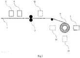
- Fig.1 is a schematic view of the measuring system used in a method for measuring the coating thickness of a steel plate according to the present invention in some embodiments.
- the measuring system used in the method for measuring the coating thickness of a steel plate according to the present comprises: a strip thickness measuring device 3 may be an X-ray thickness gauge, which is set upstream of the coating device 2 along the running direction of the strip for measuring the strip thickness T strip of the uncoated steel strip 1, and the specific position of which may be set in the quenching coating process, or may be set at the exit of the cold rolling process before applying the coating; a strip length measuring device 4 may be a laser speedometer for measuring the strip length L of the steel strip 1 that forms coil, and its specific installation position is set upstream of the coating device 2, or set downstream of the coiler 2 and upstream of the coiler 6,that is, the device 41 in the figure; the coil size measuring device 5 may be a laser range finder for measuring the outer diameter R and the inner diameter Ro of coil with coating, and its specific installation position is set
- the measuring system used in the method for measuring the coating thickness of the steel plate according to the present invention further comprises a controlling device (not shown) which is respectively connected with the strip thickness measuring device 3, the strip length measuring device 4 and the coil size measuring device 5, to receive data of the T strip L, R, R 0 transmitted by the above measuring device, and calculate and output the coating thickness T coating .
- a controlling device (not shown) which is respectively connected with the strip thickness measuring device 3, the strip length measuring device 4 and the coil size measuring device 5, to receive data of the T strip L, R, R 0 transmitted by the above measuring device, and calculate and output the coating thickness T coating .
- the X-ray thickness gauge, the laser speedometer, and the laser range finder are all commonly used equipment in the prior art, and the structural features thereof are not described herein.
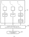
- Fig.2 is a schematic view showing a measuring step of the method for measuring the coating thickness of a steel plate according to the present invention. It can be seen that the step 11 is to use the strip thickness measuring device 3 to measure the strip thickness T strip of the steel strip, the strip length measuring device 4 to measure the length L of the steel strip, the coil size measuring device 5 to measure outer diameter R and inner diameter R 0 of the coil with coating.
- Example 1-5 After quenching, the steel strips of Example 1-5 were applied coating of Al 2 O 3 by a two-roll coater, and were coiled after Al 2 O 3 was dried.
- the running speed of the steel strip is 50-120 m/min
- the strip thickness before applying coating is 0.14-0.35 mm
- the length of the steel strip that forms the coil is 6000-16000m
- the weight of the coil with coating is 14-21t.
- the strip thickness T strip before applying the coating was measured with an X-ray thickness gauge, the length L of the steel strip that forms coil was measured with a laser speedometer, and the outer diameter R and inner diameter R 0 of the coil with coating was measured by a laser range finder, wherein the measurement accuracy of the X-ray thickness gauge is ⁇ 0.14 ⁇ m, the measurement accuracy of the laser speedometer is ⁇ 0.5 ⁇ L, and the measurement accuracy of the laser range finder is ⁇ 1mm.
- Table 1 lists the values of the outer diameter R of the coil with coating, the inner diameter Ro of the coil with coating, the length L of the coiled strip, and the strip thickness T strip of steel strip before applying coating measured in Examples 1-5, and the calculated coating thickness T coating and the measurement accuracy of coating thickness ⁇ T coating of the coating thickness.
- Example 6-41 After quenching, the steel strips of Example 6-41 were applied coating of Al 2 O 3 by a two-roll coater, and was coiled after Al 2 O 3 was dried.
- the strip thickness T strip before applying the coating was measured with an X-ray thickness gauge
- the length L of the steel strip that forms coil was measured with a laser speedometer
- the outer diameter R and inner diameter Ro of the coil with coating was measured by a laser range finder, wherein the measurement accuracy of the X-ray thickness gauge is ⁇ 0.14 ⁇ m
- the measurement accuracy of the laser speedometer is ⁇ 0.5 ⁇ L
- the measurement accuracy of the laser range finder is ⁇ 1mm.
- Table 2-1 lists the measurement deviations of the outer diameter R of the coated steel coils in Examples 6-14 and the measurement deviation of the coating thickness at this deviation.
- Table 2-2 lists the measurement deviation of the inner diameter R 0 of the coated steel coil in Examples 15-23 and the measurement deviation of the coating thickness under this deviation.
- Table 2-3 lists the measurement deviation of the strip length L of steel strip that forms coil in Example 24-32 and measurement deviation of the coating thickness at this deviation.
- Table 2-4 lists the measurement deviation of uncoated steel strip thickness T strip in Examples 33-41 and the measurement deviation of the coating thickness at this deviation.
- the measurement deviation of the coating thickness is calculated by using the T coating obtained by the measurement in the present invention and the theoretical value of the coating thickness of the steel plate, that is, the example 6-41 is intended to verify: whether the calculated coating thickness measurement is accurate and the difference between the calculated coating thickness and its theoretical value when the selected measuring instrument has a measurement deviation.
- the coating thickness measurement deviation of Example 6 was the largest (-6.67%), and the coating thickness measurement deviation of Examples 10, 19, 28, and 37 were the smallest (0.00%). According to known in the art, the measurement deviation of the coating thickness of the steel plate below 10% is high accuracy, and therefore the measurement method of the present invention is with high measurement accuracy.
- the steel strip of Example 42 was applied coating of MgO by a two-roll coater, and was coiled after MgO was dried.
- the running speed of the steel strip is 85m/min.
- the strip thickness T strip before applying the coating was measured with an X-ray thickness gauge, the length L of the steel strip that forms coil was measured with a laser speedometer, and the outer diameter R and inner diameter R 0 of the coil with coating was measured by a laser range finder, wherein the measurement accuracy of the X-ray thickness gauge is ⁇ 0.14 ⁇ m, the measurement accuracy of the laser speedometer is ⁇ 0.5 ⁇ L, and the measurement accuracy of the laser range finder is ⁇ 1mm.
- Fig.3 is a graph showing the relationship between the measured coating thickness value of the steel trip as a function of the length of the coil of Example 42. It can be seen that when the coiling length is less than 500m, the measured coating thickness T coating value has some degree of distortion due to the small coiling amount of strip. When the coiling length exceeds about 500 meters, the ratio of the sum of coating thickness of two sides to the strip thickness is between 8.5% to 10.0%, and the measured coating thickness T coating tends to be stable.
- Fig.4 is a graph showing the relationship between the coating thickness measured by the measuring method according to the present invention and the thickness measured by the off-line measuring method of the prior art. It should be noted that the data of each point of the sum of the coating thicknesses of two sides/the strip thickness in the figure are excluding the data within 500-meter of coiling, and are average values of multiple measurements.
- the coating thickness of off-line measurement refers to the coating weight per unit area of the isolating agent by scraping certain area of the release agent powder off-line and weighing the isolating agent powder. It can be seen that the value of the correlation coefficient R_sq is 95.1% (R_sq is between 0 and 1.
- the value exceeds 0.7, it is considered to be correlation between the two parameters, and the closer the value is to 1, the better the correlation is).
- the correlation between the sum of the coating thicknesses of two sides/the strip thickness and the offline measured film thickness is good, indicating that the measurement accuracy of the coating thickness measured by the method of the present invention can satisfy the production requirements.
Landscapes
- Physics & Mathematics (AREA)
- General Physics & Mathematics (AREA)
- Electromagnetism (AREA)
- Length Measuring Devices With Unspecified Measuring Means (AREA)
- Length Measuring Devices By Optical Means (AREA)
- Length-Measuring Devices Using Wave Or Particle Radiation (AREA)
- Measurement Of Length, Angles, Or The Like Using Electric Or Magnetic Means (AREA)
- Application Of Or Painting With Fluid Materials (AREA)
Abstract
Description
- The present invention relates to a method and system for measuring thickness, and in particular to a method and system for measuring the coating thickness.
- In manufacturing oriented silicon steel, oxide such as MgO or Al2O3 is coated as isolating agent. The purpose of coating the oxide isolating agent is: (1) to prevent steel strips from adhering with each other during high temperature quenching; and (2) to form a magnesium silicate base layer by reacting MgO with SiO2 oxide film on the surface of the steel strip when high-temperature quenching rises to about 1100°C, which promotes desulfurization and denitrification during high-temperature purification quenching. Applying the oxide isolating agent coating and decarburization quenching are usually implemented on the same line, the main processes of which, such as solution preparation, stirring, coating, drying and the like, greatly affect the quality of oriented silicon steel products. Among them, the coating thickness control is most critical. A coating that is too thick or too thin will result in the increasing of surface defects of the final product, and wrinkles formed locally on the steel strip, and even poor magnetic performance. Therefore, in the process of producing oriented silicon steel, it is necessary to precisely control the coating thickness of the oxide isolating agent.
- Since the oxide isolating agent is in a powder form after drying and has low adhesion to the strip, it is difficult to measure its thickness. In the prior art, there are mainly two methods for measuring the thickness of oxide isolating agent coating described below.
- One is the on-line measurement, which uses the difference in the reflection intensity of the oxide isolating agent and the steel strip to the β-ray, to calculate the oxide isolating agent coating thickness. However, in the actual manufacturing, this method has poor measurement accuracy and stability, due to the reason that, on one hand, the measuring probe is easily contaminated by the isolating agent powder and is greatly affected by the environment with dust, causing frequent maintenance and calibration for measuring system; on the other hand, the isolating agent powder coating is in uneven stripe and runs fast with the steel strip, making it difficult for the measurement system to accurately capture the reflected signal of the β-ray, and bringing large measurement errors. In addition, the β-ray radiation source has a specific decay period and requires periodic replacement, which results in high measurement and maintenance costs.
- Another method is the off-line measurement, that is, taking off a sample of steel strip coated with isolating agent, scraping the isolating agent powder by certain area, and weighing the scraped powder off-line, thus the coating weight per unit area of the isolating agent could be converted. The method has high measurement accuracy and has high requirement of standardization operation in sampling process. However, since the sampling, sample delivery and weighing are done manually, incomplete powder scraping, excessive scraping area, or even accidental sweat dripping into the sample during the powder scraping process will cause distortion of the measurement results. The labor and management cost of this method is high, and the method is only used for calibration of the coating thickness measurement system. In addition, since the method is an off-line measurement, thus has poor timeliness and on-line-ability, and it is difficult to achieve quick adjustment of the coating thickness.
- Based on this, it is expected to develop a method for measuring the coating thickness of steel strip, which can measure in real time, and with low measurement cost and high measurement accuracy.
- One of the purposes of the present invention is to provide a method for measuring coating thickness of steel strip, by which the coating thickness of the steel strip can be measured in real time, and at low measurement cost and with high measurement accuracy.
- In order to achieve the above purpose, the present invention provides a method for measuring coating thickness of steel plate, comprising the following steps:
prior to applying the coating, measuring the strip thickness Tstrip, and strip length L of steel strip that forms coil, and after applying the coating, coiling the steel strip to form a coil and measuring outer diameter R and inner diameter R0 of the coil with coating, obtaining the coating thickness Tcoating according to the following formula:
- In the above measuring method, the strip length L could be the total length of the strip to be measured, or could be the length of the coiled strip coil, i.e., the coiled strip length; accordingly, R and R0 could be measured after completing the coiling, or could be measured real-time during the coiling.
- In addition, L≥500 meters, the ratio of the sum of coating thickness of two sides to the strip thickness is 8.5 to 10.0%.
- In addition, in the method for measuring coating thickness of the steel plate according to the present invention, further comprising the following step: obtaining measurement accuracy of coating thickness ΔTcoating based on the following formula:

- In addition, in the method for measuring coating thickness of the steel plate according to the present invention, ΔL is selected as ≤±5‰×L.
- In addition, in the method for measuring coating thickness of the steel plate according to the present invention, ΔL is selected as ≤±3‰×L.
- In the above preferred technical solution, in order to improve the measurement accuracy of the coating thickness, ΔL is selected as ≤±3‰×L.
- In addition, in the method for measuring coating thickness of the steel plate according to the present invention, ΔR is selected as ≤±5‰×R, and ΔR 0 is selected as ≤±5‰×R0.
- In addition, in the method for measuring coating thickness of the steel plate according to the present invention, ΔR is selected as ≤±3‰×R, and ΔR 0 is selected as ≤±3‰×R0.
- In the above preferred technical solution, in order to improve the measurement accuracy of the coating thickness, ΔR is selected as ≤±3‰×R, and ΔR 0 is selected as ≤±3‰×R0.
- In addition, in the method for measuring coating thickness of the steel plate according to the present invention, ΔTstrip is selected as ≤±5‰×Tstrip.
- In addition, in the method for measuring coating thickness of the steel plate according to the present invention, ΔTstrip is selected as ≤±3‰×Tstrip.
- In the above preferred technical solution, in order to improve the measurement accuracy of the coating thickness, ΔTstrip is selected as ≤±3‰×Tstrip.
- Further in present invention, the measuring instrument can be selected according to the allowable error range of the coating thickness of steel strip, and the theoretical value or the estimated value of R, R 0, L or ΔTstrip to satisfy the measurement requirements or production needs.
- Accordingly, another purpose of the present invention is to provide a measuring system for measuring the coating thickness of steel strip described above, by which the coating thickness of steel plate can be measured in real time at low measurement cost and high measurement accuracy.
- In order to achieve the above purpose, the present invention provides a measuring system for coating thickness of steel plate, comprising:
- steel strip thickness measuring device for measuring the thickness Tstrip of the strip prior to coating application, which is disposed upstream of the coating device along the running direction of the strip;
- strip length measuring device for measuring the length L of the strip that forms coil, which is disposed upstream of the coiling device along the running direction of the strip;
- coil size measuring device for measuring the outer diameter R and the inner diameter Ro of a coil with coating, which is disposed downstream of the coiling device along the running direction of the strip, and at the periphery of the area where the coil with coating passes;
- controlling device, which is respectively connected to the strip thickness measuring device, the strip length measuring device and the coil size measuring device, to receive the data of the Tstrip L, R, R0 transmitted by above measuring device, and calculate and output the coating thickness Tcoating based on said data.
- In the above technical solution, the measuring system adopted by the method for measuring the coating thickness of the steel plate of the present invention is capable of measuring the coating thickness of the steel plate in real time, thereby realizing online measurement of the coating thickness of the steel plate and obtaining measurement data timely.
- In addition, in the measuring system according to the present invention, the controlling device calculates and outputs the measurement accuracy of the coating thickness Tcoating based on the following formula:

- In addition, in the measuring system according to the present invention, said strip thickness measuring device is an X-ray thickness gauge, and/or the strip length measuring device is a laser speedometer based on Doppler effect, and/or the coil size measuring device is a laser rangefinder.
- In the measuring system according to the present invention, in order to improve the measurement accuracy of the coating thickness, the strip thickness measuring device is preferably an X-ray thickness gauge, and the strip length measuring device is preferably a laser speedometer based on the Doppler principle, and the coil size measuring device is preferably a laser rangefinder. It should be noted that the X-ray thickness gauge, the laser speedometer, and the laser range finder are all commonly used equipment in the prior art, and the structural features thereof are not described herein.
- Compared with the prior art, the method and the system for measuring the coating thickness of the steel plate according to the present invention have the following beneficial effects:
- (1) The method and system for measuring the coating thickness of the steel plate according to the present invention can be used for measuring the coating thickness of the steel strip in real time at low measurement cost and with high measurement accuracy, thus is beneficial to improving the quality of steel products and reducing the consumption of coating raw materials.
- (2) The method and system for measuring the coating thickness of the steel plate according to the present invention apply for measuring thickness of different coatings, and has good applicability, and is particularly suitable for the powder coating whose thickness is difficult to accurately measured by conventional methods, such as oxide isolating coating, MgO or Al2O3 in the manufacturing process of oriented silicon steel.
-
-
Fig.1 is a schematic view showing the structure of the measuring system used in the method for measuring the coating thickness of a steel plate according to some embodiments of the present invention. -
Fig.2 is a schematic view showing a measuring step of the method for measuring the coating thickness of a steel plate according to some embodiments of the present invention. -
Fig.3 is a graph showing the relationship between the measured coating thickness value of the steel trip as a function of the length of the coil of Example 42. -
Fig.4 is a graph showing the relationship between the coating thickness measured by the measuring method according to the present invention and the coating thickness measured by the off-line measuring method of the prior art. - The method and system for measuring the coating thickness of the steel plate according to the present invention will be further explained and described below with reference to the accompanying drawings and specific embodiments. However, the explanation and description are not intended to unduly limit the technical solutions of the present invention.
-
Fig.1 is a schematic view of the measuring system used in a method for measuring the coating thickness of a steel plate according to the present invention in some embodiments. It can be seen that the measuring system used in the method for measuring the coating thickness of a steel plate according to the present comprises: a strip thickness measuringdevice 3 may be an X-ray thickness gauge, which is set upstream of thecoating device 2 along the running direction of the strip for measuring the strip thickness Tstrip of the uncoated steel strip 1, and the specific position of which may be set in the quenching coating process, or may be set at the exit of the cold rolling process before applying the coating; a striplength measuring device 4 may be a laser speedometer for measuring the strip length L of the steel strip 1 that forms coil, and its specific installation position is set upstream of thecoating device 2, or set downstream of thecoiler 2 and upstream of thecoiler 6,that is, thedevice 41 in the figure; the coilsize measuring device 5 may be a laser range finder for measuring the outer diameter R and the inner diameter Ro of coil with coating, and its specific installation position is set at any position on the periphery of the coil with coating passes, that is, the coil size measuringdevice 5 or thedevice 51 or thedevice 52 in thefigure 2 . In addition, the measuring system used in the method for measuring the coating thickness of the steel plate according to the present invention further comprises a controlling device (not shown) which is respectively connected with the strip thickness measuringdevice 3, the striplength measuring device 4 and the coilsize measuring device 5, to receive data of the Tstrip L, R, R0 transmitted by the above measuring device, and calculate and output the coating thickness Tcoating . - It should be noted that the X-ray thickness gauge, the laser speedometer, and the laser range finder are all commonly used equipment in the prior art, and the structural features thereof are not described herein.
-
Fig.2 is a schematic view showing a measuring step of the method for measuring the coating thickness of a steel plate according to the present invention. It can be seen that thestep 11 is to use the strip thickness measuringdevice 3 to measure the strip thickness Tstrip of the steel strip, the strip length measuringdevice 4 to measure the length L of the steel strip, the coil size measuringdevice 5 to measure outer diameter R and inner diameter R0 of the coil with coating. Thestep 12 is to calculate coating thickness Tcoating base on the formula Tcoating =

- In the following, the technical solution will further describe the technical solution of the present invention by using specific example data and prove the beneficial effects of the present case:
- After quenching, the steel strips of Example 1-5 were applied coating of Al2O3 by a two-roll coater, and were coiled after Al2O3 was dried. The running speed of the steel strip is 50-120 m/min, the strip thickness before applying coating is 0.14-0.35 mm, the length of the steel strip that forms the coil is 6000-16000m, and the weight of the coil with coating is 14-21t. The strip thickness Tstrip before applying the coating was measured with an X-ray thickness gauge, the length L of the steel strip that forms coil was measured with a laser speedometer, and the outer diameter R and inner diameter R0 of the coil with coating was measured by a laser range finder, wherein the measurement accuracy of the X-ray thickness gauge is ±0.14µm, the measurement accuracy of the laser speedometer is ±0.5 ‰×L, and the measurement accuracy of the laser range finder is ±1mm. The coating thickness Tcoating is then calculated based on the formula


- Table 1 lists the values of the outer diameter R of the coil with coating, the inner diameter Ro of the coil with coating, the length L of the coiled strip, and the strip thickness Tstrip of steel strip before applying coating measured in Examples 1-5, and the calculated coating thickness Tcoating and the measurement accuracy of coating thickness ΔTcoating of the coating thickness.
Table 1 Running speed of steel strip (m/min) Strip thickness Tstrip (µm) inner diameter R0(mm) outer diameter R(mm) Coiled strip length L(m) coating thickness Tcoating (µm) measurement accuracy of coating thickness ΔTcoating (µm) Example 1 120 151 506 1930 15877 20.6 ± 0.24 Example 2 110 232 507 1836 9798 17.6 ± 0.31 Example 3 90 271 508 1748 7723 13.5 ± 0.36 Example 4 90 285 508 1768 7322 22.6 ± 0.38 Example 5 55 348 508 1839 6599 23.8 ± 0.44 - After quenching, the steel strips of Example 6-41 were applied coating of Al2O3 by a two-roll coater, and was coiled after Al2O3 was dried. The strip thickness Tstrip before applying the coating was measured with an X-ray thickness gauge, the length L of the steel strip that forms coil was measured with a laser speedometer, and the outer diameter R and inner diameter Ro of the coil with coating was measured by a laser range finder, wherein the measurement accuracy of the X-ray thickness gauge is ±0.14µm, the measurement accuracy of the laser speedometer is ±0.5 ‰×L, and the measurement accuracy of the laser range finder is ±1mm. The coating thickness Tcoating is then calculated based on the formula


- Table 2-1 lists the measurement deviations of the outer diameter R of the coated steel coils in Examples 6-14 and the measurement deviation of the coating thickness at this deviation. Table 2-2 lists the measurement deviation of the inner diameter R0 of the coated steel coil in Examples 15-23 and the measurement deviation of the coating thickness under this deviation. Table 2-3 lists the measurement deviation of the strip length L of steel strip that forms coil in Example 24-32 and measurement deviation of the coating thickness at this deviation. Table 2-4 lists the measurement deviation of uncoated steel strip thickness Tstrip in Examples 33-41 and the measurement deviation of the coating thickness at this deviation.
- Wherein, the measurement deviation of the coating thickness is calculated by using the Tcoating obtained by the measurement in the present invention and the theoretical value of the coating thickness of the steel plate, that is, the example 6-41 is intended to verify: whether the calculated coating thickness measurement is accurate and the difference between the calculated coating thickness and its theoretical value when the selected measuring instrument has a measurement deviation.
Table 2-1 The measured outer diameter R(mm) Measurement deviations of the outer diameter(mm) Measureme nt deviations of the outer diameter Measurement deviation of coating thickness Example 6 1831 -4 -2.2‰ -6.67% Example7 1832 -3 -1.6‰ -5.00% Example8 1833 -2 -1.1‰ -3.33% Example9 1834 -1 -0.5‰ -1.66% Example 10 1835 0 0.0‰ 0.00% Example 11 1836 1 0.5‰ 1.66% Example12 1837 2 1.1‰ 3.32% Example 13 1838 3 1.6‰ 4.97% Example14 1839 4 2.2‰ 6.62% Table 2-2 The measured inner diameter R0(mm) Measurement deviation of the inner diameter(mm) Measureme nt deviation of the inner diameter Measurement deviation of coating thickness Example 15 504 -4 -7.9‰ 1.83% Example 16 505 -3 -5.9‰ 1.37% Example 17 506 -2 -3.9‰ 0.92% Example 18 507 -1 -2.0‰ 0.46% Example 19 508 0 0.0‰ 0.00% Example 20 509 1 2.0‰ -0.46% Example 21 510 2 3.9‰ -0.92% Example 22 511 3 5.9‰ -1.39% Example 23 512 4 7.9‰ -1.85% Table 2-3 The measured length L(m) Measurement deviation of the strip length(m) Measurement deviation of the strip length Measurement deviation of coating thickness Example 24 7992 -8 -1.00‰ 1.41% Example 25 7994 -6 -0.75‰ 1.06% Example 26 7996 -4 -0.50‰ 0.70% Example 27 7998 -2 -0.25‰ 0.35% Example 28 8000 0 0.00‰ 0.00% Example 29 8002 2 0.25‰ -0.35% Example 30 8004 4 0.50‰ -0.70% Example 31 8006 6 0.75‰ -1.06% Example 32 8008 8 1.00‰ -1.41% Table 2-4 The measured strip thickness Tstrip (µm) Measurement deviation of strip thickness(µm) Measureme nt deviation of strip thickness Measurement deviation of coating thickness Example 33 284.2 -0.8 -2.81%o 3.95% Example 34 284.4 -0.6 -2.11%o 2.96% Example 35 284.6 -0.4 -1.41‰ 1.98% Example 36 284.8 -0.2 -0.70‰ 0.99% Example 37 285.0 0 0.00‰ 0.00% Example 38 285.2 0.2 0.70‰ -0.99% Example 39 285.4 0.4 1.41‰ -1.98% Example 40 285.6 0.6 2.11‰ -2.96% Example 41 285.8 0.8 2.81‰ -3.95% - Among them, the coating thickness measurement deviation of Example 6 was the largest (-6.67%), and the coating thickness measurement deviation of Examples 10, 19, 28, and 37 were the smallest (0.00%). According to known in the art, the measurement deviation of the coating thickness of the steel plate below 10% is high accuracy, and therefore the measurement method of the present invention is with high measurement accuracy.
- It can be seen from Table 2-1, Table 2-2, Table 2-3 and Table 2-4 that even if a small amount of deviation occurs in the measuring devices, the measurement deviation of coating thickness in Examples 6-41 can satisfy the normal production requirements.
- After quenching, the steel strip of Example 42 was applied coating of MgO by a two-roll coater, and was coiled after MgO was dried. The running speed of the steel strip is 85m/min. The strip thickness Tstrip before applying the coating was measured with an X-ray thickness gauge, the length L of the steel strip that forms coil was measured with a laser speedometer, and the outer diameter R and inner diameter R0 of the coil with coating was measured by a laser range finder, wherein the measurement accuracy of the X-ray thickness gauge is ±0.14µm, the measurement accuracy of the laser speedometer is ±0.5 ‰×L, and the measurement accuracy of the laser range finder is ±1mm. The coating thickness Tcoating coating is then calculated based on the formula

-
Fig.3 is a graph showing the relationship between the measured coating thickness value of the steel trip as a function of the length of the coil of Example 42. It can be seen that when the coiling length is less than 500m, the measured coating thickness Tcoating value has some degree of distortion due to the small coiling amount of strip. When the coiling length exceeds about 500 meters, the ratio of the sum of coating thickness of two sides to the strip thickness is between 8.5% to 10.0%, and the measured coating thickness Tcoating tends to be stable. -
Fig.4 is a graph showing the relationship between the coating thickness measured by the measuring method according to the present invention and the thickness measured by the off-line measuring method of the prior art. It should be noted that the data of each point of the sum of the coating thicknesses of two sides/the strip thickness in the figure are excluding the data within 500-meter of coiling, and are average values of multiple measurements. The coating thickness of off-line measurement refers to the coating weight per unit area of the isolating agent by scraping certain area of the release agent powder off-line and weighing the isolating agent powder. It can be seen that the value of the correlation coefficient R_sq is 95.1% (R_sq is between 0 and 1. Generally speaking, when the value exceeds 0.7, it is considered to be correlation between the two parameters, and the closer the value is to 1, the better the correlation is). The correlation between the sum of the coating thicknesses of two sides/the strip thickness and the offline measured film thickness is good, indicating that the measurement accuracy of the coating thickness measured by the method of the present invention can satisfy the production requirements. - It should be noted that the prior art in the scope of protection of the present invention is not limited to the embodiments given in the present application, and all prior art that does not contradict the solution of the present invention includes, but is not limited to, prior patent documents, prior publications, prior disclosure, and the like can be included in the scope of protection of the present invention.
- In addition, the combination of the technical features in the present invention is not limited to the combination described in the claims of the present invention or the combination described in the specific embodiments, and all the technical features described in the present invention can be freely combined or combined in any manner unless there is a contradiction between each other.
- It should also be noted that the above-exemplified embodiments are merely specific embodiments of the invention. It is obvious that the present invention is not limited to the above embodiments, and similar changes or modifications which are made by those skilled in the art can be directly derived from the disclosure of the present invention or can be easily ascertained, are all within the scope of protection of the present invention.
Claims (9)
- A method for measuring coating thickness of steel plate, comprising the following steps:prior to applying the coating, measuring the strip thickness Tstrip, and strip length L of steel strip that forms coil, and after applying the coating, coiling the steel strip to form a coil and measuring outer diameter R and inner diameter R0 of the coil with coating,obtaining the coating thickness Tcoating according to the following formula

- The method for measuring coating thickness of steel plate according to claim 1, wherein strip length L≥500 meters, the ratio of the sum of coating thickness of two sides to the strip thickness is 8.5 to 10.0%.
- The method for measuring coating thickness of steel plate according to claim 1, further comprising the following step:
obtaining measurement accuracy of coating thickness ΔTcoating based on the following formula
- The method for measuring coating thickness of steel plate according to claim 3, wherein ΔL is selected as ≤±3‰×L.
- The method for measuring coating thickness of steel plate according to claim 3, wherein ΔR is selected as ≤±3‰×R, and ΔR 0 is selected as ≤±3‰×R0.
- The method for measuring coating thickness of steel plate according to claim 3, wherein ΔTstrip is selected as ≤±3‰×Tstrip
- A measuring system for coating thickness of steel plate, comprising:steel strip thickness measuring device for measuring the thickness Tstrip of the strip prior to coating application, which is disposed upstream of the coating device along the running direction of the strip;strip length measuring device for measuring the length L of the strip that forms coil, which is disposed upstream of the coiler along the running direction of the strip;coil size measuring device for measuring the outer diameter R and the inner diameter Ro of a coil with coating, which is disposed downstream of the coiler along the running direction of the strip, and at the periphery of the area where the coil with coating passes;controlling device, which is respectively connected to the strip thickness measuring device, the strip length measuring device and the coil size measuring device, to receive the data of the Tstrip L, R, R0 transmitted by above measuring device, and calculate and output the coating thickness Tcoating based on said data.
- The measuring system according to claim 7, wherein said control device calculates and outputs coating thickness measurement accuracy ΔTcoating based on the following formula:

- The measuring system according to claim 7 or 8, wherein the strip thickness measuring device is an X-ray thickness gauge, and/or the strip length measuring device is a laser speedometer based on Doppler effect, and/or the coil size measuring device is a laser rangefinder.
Applications Claiming Priority (2)
| Application Number | Priority Date | Filing Date | Title |
|---|---|---|---|
| CN201810270900.6A CN110319795B (en) | 2018-03-29 | 2018-03-29 | Method and system for measuring thickness of steel plate coating |
| PCT/CN2019/080450 WO2019185028A1 (en) | 2018-03-29 | 2019-03-29 | Method and system for measuring thickness of coating of steel plate |
Publications (3)
| Publication Number | Publication Date |
|---|---|
| EP3767225A1 true EP3767225A1 (en) | 2021-01-20 |
| EP3767225A4 EP3767225A4 (en) | 2021-06-09 |
| EP3767225B1 EP3767225B1 (en) | 2023-06-14 |
Family
ID=68058593
Family Applications (1)
| Application Number | Title | Priority Date | Filing Date |
|---|---|---|---|
| EP19774217.4A Active EP3767225B1 (en) | 2018-03-29 | 2019-03-29 | Method and system for measuring thickness of coating of steel plate |
Country Status (7)
| Country | Link |
|---|---|
| EP (1) | EP3767225B1 (en) |
| JP (1) | JP7065998B2 (en) |
| KR (1) | KR102431799B1 (en) |
| CN (1) | CN110319795B (en) |
| CA (1) | CA3093619C (en) |
| MX (1) | MX2020010048A (en) |
| WO (1) | WO2019185028A1 (en) |
Families Citing this family (9)
| Publication number | Priority date | Publication date | Assignee | Title |
|---|---|---|---|---|
| CN110906897B (en) * | 2019-12-16 | 2022-02-01 | 唐山盈和瑞环保设备有限公司 | Online quality tester for anticorrosive coating of steel plate |
| CN112556583B (en) * | 2020-12-10 | 2023-01-13 | 海鸿电气有限公司 | Rectangular multilayer amorphous alloy strip length measuring device of three-dimensional wound core transformer |
| CN113118043B (en) * | 2021-03-10 | 2023-05-02 | 华奈克(武汉)汽车部件有限公司 | Ignition coil iron core's surface coating thickness detection device |
| CN113673052A (en) * | 2021-08-17 | 2021-11-19 | 北京首钢冷轧薄板有限公司 | Method, device, medium and computer equipment for determining outer diameter of steel coil |
| CN113984528B (en) * | 2021-11-16 | 2024-11-05 | 湖北省建筑科学研究设计院股份有限公司 | Measurement method and device for improving the measurement accuracy of prestressed tendon shrinkage |
| CN114353717B (en) * | 2021-11-25 | 2023-08-29 | 安徽飞达电气科技有限公司 | Online thickness measuring device for capacitor film |
| CN116952639A (en) * | 2022-03-31 | 2023-10-27 | 宝山钢铁股份有限公司 | Cold-rolled sheet online sampling method and system based on mechanical property real-time data |
| CN118635283B (en) * | 2024-06-04 | 2025-11-25 | 中铝瑞闽股份有限公司 | Method for adjusting the pressing depth of the tension roller according to the thickness of the aluminum coil being fed |
| CN119437124B (en) * | 2025-01-13 | 2025-05-02 | 通变电器有限公司 | Transformer silicon steel sheet measuring table |
Family Cites Families (27)
| Publication number | Priority date | Publication date | Assignee | Title |
|---|---|---|---|---|
| JPS525306B2 (en) * | 1972-08-25 | 1977-02-12 | ||
| JPS54125054A (en) * | 1978-03-22 | 1979-09-28 | Toshiba Corp | Mean plate thickness measuring apparatus |
| JPS6235210A (en) * | 1985-08-09 | 1987-02-16 | Nippon Kokan Kk <Nkk> | Plate thickness measuring instrument for hot rolled steel plate |
| JPH02178172A (en) * | 1988-12-28 | 1990-07-11 | Nkk Corp | How to unwind the coil |
| JPH03200004A (en) * | 1989-12-28 | 1991-09-02 | Kawasaki Steel Corp | Measuring instrument for coat film thickness |
| JP3922400B2 (en) * | 1997-03-11 | 2007-05-30 | 本田技研工業株式会社 | Backlash shim selection method and apparatus |
| US7057735B2 (en) * | 2002-11-14 | 2006-06-06 | Fitel U.S.A. Corp. | Method for measuring the optical and physical thickness of optically transparent objects |
| US6903339B2 (en) * | 2002-11-26 | 2005-06-07 | The Boeing Company | Method of measuring thickness of an opaque coating using infrared absorbance |
| JP2006155758A (en) * | 2004-11-30 | 2006-06-15 | Fuji Photo Film Co Ltd | Method for treating tape |
| CA2672685C (en) * | 2006-12-15 | 2011-07-12 | Fraunhofer-Gesellschaft Zur Foerderung Der Angewandten Forschung E.V. | Method and apparatus for thickness measurement |
| CN100483069C (en) * | 2007-05-23 | 2009-04-29 | 河北工业大学 | Detecting device and method for pipeline wall thickness |
| US8142882B1 (en) * | 2007-11-14 | 2012-03-27 | The Crump Group, Inc. | Method and apparatus for cross-sectional scanning of parts |
| JP4846741B2 (en) * | 2008-02-06 | 2011-12-28 | 新日本製鐵株式会社 | Oxide film thickness measuring method and oxide film thickness measuring apparatus |
| JP2009275243A (en) | 2008-05-13 | 2009-11-26 | Mitsubishi-Hitachi Metals Machinery Inc | Method for measuring mass of plated film per unit area on hot-dip metal-plated steel sheet, and device for measuring mass of plated film per unit area |
| JP4888495B2 (en) * | 2009-01-20 | 2012-02-29 | 株式会社デンソー | Linear solenoid |
| WO2011014262A1 (en) * | 2009-07-31 | 2011-02-03 | The Mill Steel Co. | Apparatus for determining gauge profile for flat rolled material with laser-based lap counter |
| JP2011242254A (en) * | 2010-05-18 | 2011-12-01 | Nippon Steel Corp | Steel plate thickness measuring instrument and calibration method thereof |
| US9605940B2 (en) * | 2011-05-25 | 2017-03-28 | Helmut Fischer GbmH Institut für Elektronik und Messtechnik | Measuring probe for measuring the thickness of thin layers, and method for the production of a sensor element for the measuring probe |
| CN103363910A (en) * | 2012-03-30 | 2013-10-23 | 鞍钢股份有限公司 | Method for measuring average thickness of oxide scale on surface of hot-rolled wire rod |
| CN103372523B (en) * | 2012-04-26 | 2016-08-24 | 宝山钢铁股份有限公司 | A kind of coating layer thickness control method of two roll coatings |
| CN102873956A (en) * | 2012-09-28 | 2013-01-16 | 常熟华冶薄板有限公司 | Color coated steel plate with vibration and noise reduction functions and method for manufacturing color coated steel plate |
| CN103453839A (en) * | 2013-09-06 | 2013-12-18 | 鞍钢股份有限公司 | Method for measuring coating thickness by confocal measurement |
| CN103486973B (en) * | 2013-09-18 | 2016-03-30 | 镇江耐丝新型材料有限公司 | A kind of measuring method of diamond wire thickness of coating |
| CN104142280B (en) * | 2013-10-16 | 2016-08-10 | 富耐克超硬材料股份有限公司 | A kind of method detecting hard coat quality |
| JP5783288B1 (en) * | 2014-03-12 | 2015-09-24 | パルステック工業株式会社 | Surface profile measuring device and translucent object thickness measuring device |
| CN105651192A (en) * | 2016-04-12 | 2016-06-08 | 广州市尤特新材料有限公司 | Detection method and system of surface thickness and planeness of rotary target |
| CN107830810B (en) * | 2017-12-07 | 2019-11-01 | 南方电网科学研究院有限责任公司 | Method and system for measuring thickness of coating |
-
2018
- 2018-03-29 CN CN201810270900.6A patent/CN110319795B/en active Active
-
2019
- 2019-03-29 WO PCT/CN2019/080450 patent/WO2019185028A1/en not_active Ceased
- 2019-03-29 JP JP2020551993A patent/JP7065998B2/en active Active
- 2019-03-29 CA CA3093619A patent/CA3093619C/en active Active
- 2019-03-29 KR KR1020207026467A patent/KR102431799B1/en active Active
- 2019-03-29 EP EP19774217.4A patent/EP3767225B1/en active Active
- 2019-03-29 MX MX2020010048A patent/MX2020010048A/en unknown
Also Published As
| Publication number | Publication date |
|---|---|
| CN110319795A (en) | 2019-10-11 |
| CN110319795B (en) | 2021-10-19 |
| KR102431799B1 (en) | 2022-08-11 |
| MX2020010048A (en) | 2020-10-15 |
| EP3767225A4 (en) | 2021-06-09 |
| CA3093619C (en) | 2023-03-21 |
| JP2021516622A (en) | 2021-07-08 |
| KR20200120721A (en) | 2020-10-21 |
| CA3093619A1 (en) | 2019-10-03 |
| JP7065998B2 (en) | 2022-05-12 |
| EP3767225B1 (en) | 2023-06-14 |
| WO2019185028A1 (en) | 2019-10-03 |
Similar Documents
| Publication | Publication Date | Title |
|---|---|---|
| EP3767225B1 (en) | Method and system for measuring thickness of coating of steel plate | |
| US10222343B2 (en) | Method and apparatus for testing residual stress in coatings | |
| CN102478395B (en) | Method for on-line detection of thickness of non-chromium coating of strip steel surface | |
| CN111482465A (en) | Plate shape control method and device for plate and strip | |
| CN110487496B (en) | Method for identifying bridge deflection based on long gauge length strain by improved bending moment area method | |
| CN115646761B (en) | Coating surface density online detection method and device and battery coating equipment | |
| CN110548769A (en) | Method for early warning thickness deviation of strip steel on line | |
| CN101134207A (en) | Processing method of hot-rolled incoming material crown in calculation of cold-rolled strip shape setting | |
| CN117232456A (en) | Accurate detection system and detection method for rolled thickness of aluminum plate strip foil | |
| CN105486252A (en) | Aluminum-zinc-plated layer thickness measurement compensation method | |
| CN105032953B (en) | Fast sample plate calibration method of gamma-ray thickness gauge | |
| CN105107849B (en) | A kind of hot continuous rolling workpiece thickness computational methods | |
| GB2046900A (en) | Method of controlling the thickness of a moving web | |
| DE102022113728A1 (en) | Method for measuring changes in distance to a measurement object | |
| CN115463977B (en) | Reliability verification method for thickness gauge in rolling mill thickness measuring system | |
| CN103934287A (en) | Method for precisely measuring width of steel plate at finish rolling outlet | |
| CN110987255B (en) | High-precision film stress online testing method and device | |
| CN110553616B (en) | Method for measuring thickness of special-shaped surface coating | |
| US20040111235A1 (en) | Ultrasonic gauge online calibration system | |
| EP4635643A1 (en) | Entry angle enlargement inhibiting device and method of manufacturing enameled wire | |
| CN116713331A (en) | A plate shape control method for rolling 0.015mm ultra-thin stainless steel precision strip | |
| JPS5841610A (en) | Rolling method for thick plate | |
| CN115790328A (en) | High-precision metering roller gap correction method for gluing machine in copper-clad plate industry | |
| Hudomalj et al. | Analysis and Comparison of In Situ Coating Thickness Measurements Using Two Different Sensing Techniques | |
| JP3152524B2 (en) | Method of controlling thickness of rolled material in hot continuous rolling |
Legal Events
| Date | Code | Title | Description |
|---|---|---|---|
| STAA | Information on the status of an ep patent application or granted ep patent |
Free format text: STATUS: THE INTERNATIONAL PUBLICATION HAS BEEN MADE |
|
| PUAI | Public reference made under article 153(3) epc to a published international application that has entered the european phase |
Free format text: ORIGINAL CODE: 0009012 |
|
| STAA | Information on the status of an ep patent application or granted ep patent |
Free format text: STATUS: REQUEST FOR EXAMINATION WAS MADE |
|
| 17P | Request for examination filed |
Effective date: 20201013 |
|
| AK | Designated contracting states |
Kind code of ref document: A1 Designated state(s): AL AT BE BG CH CY CZ DE DK EE ES FI FR GB GR HR HU IE IS IT LI LT LU LV MC MK MT NL NO PL PT RO RS SE SI SK SM TR |
|
| AX | Request for extension of the european patent |
Extension state: BA ME |
|
| REG | Reference to a national code |
Ref country code: DE Ref legal event code: R079 Free format text: PREVIOUS MAIN CLASS: G01B0011060000 Ipc: G01B0021080000 Ref document number: 602019031090 Country of ref document: DE |
|
| A4 | Supplementary search report drawn up and despatched |
Effective date: 20210510 |
|
| RIC1 | Information provided on ipc code assigned before grant |
Ipc: G01B 21/08 20060101AFI20210503BHEP |
|
| DAV | Request for validation of the european patent (deleted) | ||
| DAX | Request for extension of the european patent (deleted) | ||
| GRAP | Despatch of communication of intention to grant a patent |
Free format text: ORIGINAL CODE: EPIDOSNIGR1 |
|
| STAA | Information on the status of an ep patent application or granted ep patent |
Free format text: STATUS: GRANT OF PATENT IS INTENDED |
|
| INTG | Intention to grant announced |
Effective date: 20230209 |
|
| GRAS | Grant fee paid |
Free format text: ORIGINAL CODE: EPIDOSNIGR3 |
|
| GRAA | (expected) grant |
Free format text: ORIGINAL CODE: 0009210 |
|
| STAA | Information on the status of an ep patent application or granted ep patent |
Free format text: STATUS: THE PATENT HAS BEEN GRANTED |
|
| AK | Designated contracting states |
Kind code of ref document: B1 Designated state(s): AL AT BE BG CH CY CZ DE DK EE ES FI FR GB GR HR HU IE IS IT LI LT LU LV MC MK MT NL NO PL PT RO RS SE SI SK SM TR |
|
| P01 | Opt-out of the competence of the unified patent court (upc) registered |
Effective date: 20230508 |
|
| REG | Reference to a national code |
Ref country code: CH Ref legal event code: EP |
|
| REG | Reference to a national code |
Ref country code: DE Ref legal event code: R096 Ref document number: 602019031090 Country of ref document: DE |
|
| REG | Reference to a national code |
Ref country code: AT Ref legal event code: REF Ref document number: 1579513 Country of ref document: AT Kind code of ref document: T Effective date: 20230715 |
|
| REG | Reference to a national code |
Ref country code: LT Ref legal event code: MG9D |
|
| REG | Reference to a national code |
Ref country code: NL Ref legal event code: MP Effective date: 20230614 |
|
| PG25 | Lapsed in a contracting state [announced via postgrant information from national office to epo] |
Ref country code: SE Free format text: LAPSE BECAUSE OF FAILURE TO SUBMIT A TRANSLATION OF THE DESCRIPTION OR TO PAY THE FEE WITHIN THE PRESCRIBED TIME-LIMIT Effective date: 20230614 Ref country code: NO Free format text: LAPSE BECAUSE OF FAILURE TO SUBMIT A TRANSLATION OF THE DESCRIPTION OR TO PAY THE FEE WITHIN THE PRESCRIBED TIME-LIMIT Effective date: 20230914 Ref country code: ES Free format text: LAPSE BECAUSE OF FAILURE TO SUBMIT A TRANSLATION OF THE DESCRIPTION OR TO PAY THE FEE WITHIN THE PRESCRIBED TIME-LIMIT Effective date: 20230614 |
|
| REG | Reference to a national code |
Ref country code: AT Ref legal event code: MK05 Ref document number: 1579513 Country of ref document: AT Kind code of ref document: T Effective date: 20230614 |
|
| PG25 | Lapsed in a contracting state [announced via postgrant information from national office to epo] |
Ref country code: RS Free format text: LAPSE BECAUSE OF FAILURE TO SUBMIT A TRANSLATION OF THE DESCRIPTION OR TO PAY THE FEE WITHIN THE PRESCRIBED TIME-LIMIT Effective date: 20230614 Ref country code: NL Free format text: LAPSE BECAUSE OF FAILURE TO SUBMIT A TRANSLATION OF THE DESCRIPTION OR TO PAY THE FEE WITHIN THE PRESCRIBED TIME-LIMIT Effective date: 20230614 Ref country code: LV Free format text: LAPSE BECAUSE OF FAILURE TO SUBMIT A TRANSLATION OF THE DESCRIPTION OR TO PAY THE FEE WITHIN THE PRESCRIBED TIME-LIMIT Effective date: 20230614 Ref country code: LT Free format text: LAPSE BECAUSE OF FAILURE TO SUBMIT A TRANSLATION OF THE DESCRIPTION OR TO PAY THE FEE WITHIN THE PRESCRIBED TIME-LIMIT Effective date: 20230614 Ref country code: HR Free format text: LAPSE BECAUSE OF FAILURE TO SUBMIT A TRANSLATION OF THE DESCRIPTION OR TO PAY THE FEE WITHIN THE PRESCRIBED TIME-LIMIT Effective date: 20230614 Ref country code: GR Free format text: LAPSE BECAUSE OF FAILURE TO SUBMIT A TRANSLATION OF THE DESCRIPTION OR TO PAY THE FEE WITHIN THE PRESCRIBED TIME-LIMIT Effective date: 20230915 |
|
| PG25 | Lapsed in a contracting state [announced via postgrant information from national office to epo] |
Ref country code: FI Free format text: LAPSE BECAUSE OF FAILURE TO SUBMIT A TRANSLATION OF THE DESCRIPTION OR TO PAY THE FEE WITHIN THE PRESCRIBED TIME-LIMIT Effective date: 20230614 |
|
| PG25 | Lapsed in a contracting state [announced via postgrant information from national office to epo] |
Ref country code: SK Free format text: LAPSE BECAUSE OF FAILURE TO SUBMIT A TRANSLATION OF THE DESCRIPTION OR TO PAY THE FEE WITHIN THE PRESCRIBED TIME-LIMIT Effective date: 20230614 |
|
| PG25 | Lapsed in a contracting state [announced via postgrant information from national office to epo] |
Ref country code: IS Free format text: LAPSE BECAUSE OF FAILURE TO SUBMIT A TRANSLATION OF THE DESCRIPTION OR TO PAY THE FEE WITHIN THE PRESCRIBED TIME-LIMIT Effective date: 20231014 |
|
| PG25 | Lapsed in a contracting state [announced via postgrant information from national office to epo] |
Ref country code: SM Free format text: LAPSE BECAUSE OF FAILURE TO SUBMIT A TRANSLATION OF THE DESCRIPTION OR TO PAY THE FEE WITHIN THE PRESCRIBED TIME-LIMIT Effective date: 20230614 Ref country code: SK Free format text: LAPSE BECAUSE OF FAILURE TO SUBMIT A TRANSLATION OF THE DESCRIPTION OR TO PAY THE FEE WITHIN THE PRESCRIBED TIME-LIMIT Effective date: 20230614 Ref country code: RO Free format text: LAPSE BECAUSE OF FAILURE TO SUBMIT A TRANSLATION OF THE DESCRIPTION OR TO PAY THE FEE WITHIN THE PRESCRIBED TIME-LIMIT Effective date: 20230614 Ref country code: PT Free format text: LAPSE BECAUSE OF FAILURE TO SUBMIT A TRANSLATION OF THE DESCRIPTION OR TO PAY THE FEE WITHIN THE PRESCRIBED TIME-LIMIT Effective date: 20231016 Ref country code: IS Free format text: LAPSE BECAUSE OF FAILURE TO SUBMIT A TRANSLATION OF THE DESCRIPTION OR TO PAY THE FEE WITHIN THE PRESCRIBED TIME-LIMIT Effective date: 20231014 Ref country code: EE Free format text: LAPSE BECAUSE OF FAILURE TO SUBMIT A TRANSLATION OF THE DESCRIPTION OR TO PAY THE FEE WITHIN THE PRESCRIBED TIME-LIMIT Effective date: 20230614 Ref country code: CZ Free format text: LAPSE BECAUSE OF FAILURE TO SUBMIT A TRANSLATION OF THE DESCRIPTION OR TO PAY THE FEE WITHIN THE PRESCRIBED TIME-LIMIT Effective date: 20230614 Ref country code: AT Free format text: LAPSE BECAUSE OF FAILURE TO SUBMIT A TRANSLATION OF THE DESCRIPTION OR TO PAY THE FEE WITHIN THE PRESCRIBED TIME-LIMIT Effective date: 20230614 |
|
| PG25 | Lapsed in a contracting state [announced via postgrant information from national office to epo] |
Ref country code: PL Free format text: LAPSE BECAUSE OF FAILURE TO SUBMIT A TRANSLATION OF THE DESCRIPTION OR TO PAY THE FEE WITHIN THE PRESCRIBED TIME-LIMIT Effective date: 20230614 |
|
| REG | Reference to a national code |
Ref country code: DE Ref legal event code: R097 Ref document number: 602019031090 Country of ref document: DE |
|
| PLBE | No opposition filed within time limit |
Free format text: ORIGINAL CODE: 0009261 |
|
| STAA | Information on the status of an ep patent application or granted ep patent |
Free format text: STATUS: NO OPPOSITION FILED WITHIN TIME LIMIT |
|
| PG25 | Lapsed in a contracting state [announced via postgrant information from national office to epo] |
Ref country code: DK Free format text: LAPSE BECAUSE OF FAILURE TO SUBMIT A TRANSLATION OF THE DESCRIPTION OR TO PAY THE FEE WITHIN THE PRESCRIBED TIME-LIMIT Effective date: 20230614 |
|
| PG25 | Lapsed in a contracting state [announced via postgrant information from national office to epo] |
Ref country code: SI Free format text: LAPSE BECAUSE OF FAILURE TO SUBMIT A TRANSLATION OF THE DESCRIPTION OR TO PAY THE FEE WITHIN THE PRESCRIBED TIME-LIMIT Effective date: 20230614 |
|
| 26N | No opposition filed |
Effective date: 20240315 |
|
| PG25 | Lapsed in a contracting state [announced via postgrant information from national office to epo] |
Ref country code: SI Free format text: LAPSE BECAUSE OF FAILURE TO SUBMIT A TRANSLATION OF THE DESCRIPTION OR TO PAY THE FEE WITHIN THE PRESCRIBED TIME-LIMIT Effective date: 20230614 |
|
| REG | Reference to a national code |
Ref country code: CH Ref legal event code: PL |
|
| PG25 | Lapsed in a contracting state [announced via postgrant information from national office to epo] |
Ref country code: BG Free format text: LAPSE BECAUSE OF FAILURE TO SUBMIT A TRANSLATION OF THE DESCRIPTION OR TO PAY THE FEE WITHIN THE PRESCRIBED TIME-LIMIT Effective date: 20230614 |
|
| PG25 | Lapsed in a contracting state [announced via postgrant information from national office to epo] |
Ref country code: LU Free format text: LAPSE BECAUSE OF NON-PAYMENT OF DUE FEES Effective date: 20240329 |
|
| PG25 | Lapsed in a contracting state [announced via postgrant information from national office to epo] |
Ref country code: MC Free format text: LAPSE BECAUSE OF FAILURE TO SUBMIT A TRANSLATION OF THE DESCRIPTION OR TO PAY THE FEE WITHIN THE PRESCRIBED TIME-LIMIT Effective date: 20230614 |
|
| GBPC | Gb: european patent ceased through non-payment of renewal fee |
Effective date: 20240329 |
|
| PG25 | Lapsed in a contracting state [announced via postgrant information from national office to epo] |
Ref country code: MC Free format text: LAPSE BECAUSE OF FAILURE TO SUBMIT A TRANSLATION OF THE DESCRIPTION OR TO PAY THE FEE WITHIN THE PRESCRIBED TIME-LIMIT Effective date: 20230614 Ref country code: LU Free format text: LAPSE BECAUSE OF NON-PAYMENT OF DUE FEES Effective date: 20240329 Ref country code: BG Free format text: LAPSE BECAUSE OF FAILURE TO SUBMIT A TRANSLATION OF THE DESCRIPTION OR TO PAY THE FEE WITHIN THE PRESCRIBED TIME-LIMIT Effective date: 20230614 |
|
| REG | Reference to a national code |
Ref country code: BE Ref legal event code: MM Effective date: 20240331 |
|
| PG25 | Lapsed in a contracting state [announced via postgrant information from national office to epo] |
Ref country code: BE Free format text: LAPSE BECAUSE OF NON-PAYMENT OF DUE FEES Effective date: 20240331 |
|
| PG25 | Lapsed in a contracting state [announced via postgrant information from national office to epo] |
Ref country code: GB Free format text: LAPSE BECAUSE OF NON-PAYMENT OF DUE FEES Effective date: 20240329 |
|
| PG25 | Lapsed in a contracting state [announced via postgrant information from national office to epo] |
Ref country code: FR Free format text: LAPSE BECAUSE OF NON-PAYMENT OF DUE FEES Effective date: 20240331 |
|
| PG25 | Lapsed in a contracting state [announced via postgrant information from national office to epo] |
Ref country code: IE Free format text: LAPSE BECAUSE OF NON-PAYMENT OF DUE FEES Effective date: 20240329 |
|
| PG25 | Lapsed in a contracting state [announced via postgrant information from national office to epo] |
Ref country code: IE Free format text: LAPSE BECAUSE OF NON-PAYMENT OF DUE FEES Effective date: 20240329 Ref country code: GB Free format text: LAPSE BECAUSE OF NON-PAYMENT OF DUE FEES Effective date: 20240329 Ref country code: FR Free format text: LAPSE BECAUSE OF NON-PAYMENT OF DUE FEES Effective date: 20240331 Ref country code: BE Free format text: LAPSE BECAUSE OF NON-PAYMENT OF DUE FEES Effective date: 20240331 Ref country code: CH Free format text: LAPSE BECAUSE OF NON-PAYMENT OF DUE FEES Effective date: 20240331 |
|
| PG25 | Lapsed in a contracting state [announced via postgrant information from national office to epo] |
Ref country code: CY Free format text: LAPSE BECAUSE OF FAILURE TO SUBMIT A TRANSLATION OF THE DESCRIPTION OR TO PAY THE FEE WITHIN THE PRESCRIBED TIME-LIMIT; INVALID AB INITIO Effective date: 20190329 |
|
| PG25 | Lapsed in a contracting state [announced via postgrant information from national office to epo] |
Ref country code: HU Free format text: LAPSE BECAUSE OF FAILURE TO SUBMIT A TRANSLATION OF THE DESCRIPTION OR TO PAY THE FEE WITHIN THE PRESCRIBED TIME-LIMIT; INVALID AB INITIO Effective date: 20190329 |
|
| PGFP | Annual fee paid to national office [announced via postgrant information from national office to epo] |
Ref country code: DE Payment date: 20260313 Year of fee payment: 8 |
|
| PGFP | Annual fee paid to national office [announced via postgrant information from national office to epo] |
Ref country code: IT Payment date: 20260309 Year of fee payment: 8 |
|
| PGFP | Annual fee paid to national office [announced via postgrant information from national office to epo] |
Ref country code: TR Payment date: 20260313 Year of fee payment: 8 |