EP3767138A1 - Seal device - Google Patents
Seal device Download PDFInfo
- Publication number
- EP3767138A1 EP3767138A1 EP19767477.3A EP19767477A EP3767138A1 EP 3767138 A1 EP3767138 A1 EP 3767138A1 EP 19767477 A EP19767477 A EP 19767477A EP 3767138 A1 EP3767138 A1 EP 3767138A1
- Authority
- EP
- European Patent Office
- Prior art keywords
- holder
- seal device
- housing
- protruding portion
- shaft hole
- Prior art date
- Legal status (The legal status is an assumption and is not a legal conclusion. Google has not performed a legal analysis and makes no representation as to the accuracy of the status listed.)
- Pending
Links
- 238000007789 sealing Methods 0.000 claims abstract description 10
- 238000003780 insertion Methods 0.000 claims abstract description 3
- 230000037431 insertion Effects 0.000 claims abstract description 3
- 239000012530 fluid Substances 0.000 description 35
- 230000002093 peripheral effect Effects 0.000 description 15
- 238000012986 modification Methods 0.000 description 5
- 230000004048 modification Effects 0.000 description 5
- 230000001105 regulatory effect Effects 0.000 description 5
- XLYOFNOQVPJJNP-UHFFFAOYSA-N water Substances O XLYOFNOQVPJJNP-UHFFFAOYSA-N 0.000 description 4
- 239000000498 cooling water Substances 0.000 description 3
- 239000000463 material Substances 0.000 description 3
- 239000011347 resin Substances 0.000 description 3
- 229920005989 resin Polymers 0.000 description 3
- 239000010935 stainless steel Substances 0.000 description 3
- 229910001220 stainless steel Inorganic materials 0.000 description 3
- 230000032683 aging Effects 0.000 description 2
- 238000005520 cutting process Methods 0.000 description 2
- 230000007423 decrease Effects 0.000 description 2
- 238000009434 installation Methods 0.000 description 2
- 239000004816 latex Substances 0.000 description 2
- 229920000126 latex Polymers 0.000 description 2
- 229910000851 Alloy steel Inorganic materials 0.000 description 1
- 238000007792 addition Methods 0.000 description 1
- 238000013459 approach Methods 0.000 description 1
- 230000015572 biosynthetic process Effects 0.000 description 1
- 229920001971 elastomer Polymers 0.000 description 1
- -1 for example Substances 0.000 description 1
- 238000005242 forging Methods 0.000 description 1
- 210000004907 gland Anatomy 0.000 description 1
- 238000004519 manufacturing process Methods 0.000 description 1
- 239000002184 metal Substances 0.000 description 1
- 238000012856 packing Methods 0.000 description 1
- 238000005192 partition Methods 0.000 description 1
- 239000004810 polytetrafluoroethylene Substances 0.000 description 1
- 229920001343 polytetrafluoroethylene Polymers 0.000 description 1
- 238000003825 pressing Methods 0.000 description 1
Images




Classifications
-
- F—MECHANICAL ENGINEERING; LIGHTING; HEATING; WEAPONS; BLASTING
- F16—ENGINEERING ELEMENTS AND UNITS; GENERAL MEASURES FOR PRODUCING AND MAINTAINING EFFECTIVE FUNCTIONING OF MACHINES OR INSTALLATIONS; THERMAL INSULATION IN GENERAL
- F16J—PISTONS; CYLINDERS; SEALINGS
- F16J15/00—Sealings
- F16J15/16—Sealings between relatively-moving surfaces
- F16J15/32—Sealings between relatively-moving surfaces with elastic sealings, e.g. O-rings
- F16J15/3248—Sealings between relatively-moving surfaces with elastic sealings, e.g. O-rings provided with casings or supports
- F16J15/3252—Sealings between relatively-moving surfaces with elastic sealings, e.g. O-rings provided with casings or supports with rigid casings or supports
-
- F—MECHANICAL ENGINEERING; LIGHTING; HEATING; WEAPONS; BLASTING
- F16—ENGINEERING ELEMENTS AND UNITS; GENERAL MEASURES FOR PRODUCING AND MAINTAINING EFFECTIVE FUNCTIONING OF MACHINES OR INSTALLATIONS; THERMAL INSULATION IN GENERAL
- F16J—PISTONS; CYLINDERS; SEALINGS
- F16J15/00—Sealings
- F16J15/16—Sealings between relatively-moving surfaces
- F16J15/32—Sealings between relatively-moving surfaces with elastic sealings, e.g. O-rings
- F16J15/3204—Sealings between relatively-moving surfaces with elastic sealings, e.g. O-rings with at least one lip
- F16J15/3232—Sealings between relatively-moving surfaces with elastic sealings, e.g. O-rings with at least one lip having two or more lips
-
- F—MECHANICAL ENGINEERING; LIGHTING; HEATING; WEAPONS; BLASTING
- F16—ENGINEERING ELEMENTS AND UNITS; GENERAL MEASURES FOR PRODUCING AND MAINTAINING EFFECTIVE FUNCTIONING OF MACHINES OR INSTALLATIONS; THERMAL INSULATION IN GENERAL
- F16J—PISTONS; CYLINDERS; SEALINGS
- F16J15/00—Sealings
- F16J15/16—Sealings between relatively-moving surfaces
- F16J15/32—Sealings between relatively-moving surfaces with elastic sealings, e.g. O-rings
- F16J15/3268—Mounting of sealing rings
Definitions
- Patent Citation 1 JP 2006-300186 A (pages 5 to 7 and FIG. 2 )
- the protruding portion of the holder comes into contact with the tapered portion of shaft hole to receive a radial force. Therefore, guiding is performed in a state where an axis of the holder coincides with an axis of the shaft hole, and in a state where the protruding portion is substantially uniformly pressed toward a radially inward direction of the tapered portion to be in uniform contact with the tapered portion in a circumferential direction, the seal device is pushed in, so that the movement of the seal device is regulated. Accordingly, only a slight movement of the seal device in an axial direction is allowed; and thereby, it is possible to maintain the sealing between the housing and the rotating shaft.
- the protruding portion may be spaced apart from an inner surface of the tapered portion in an axial direction in a state where the seal device is assembled to the housing. According to this preferable configuration, until the protruding portion and the inner surface of the tapered portion come into contact with each other, no load occurs in the tapered portion, and a creep deformation is unlikely to occur in the tapered portion.
- a protrusion dimension of the protruding portion from the cylindrical portion of the holder may be smaller than a thickness of the cylindrical portion. According to this preferable configuration, it is possible to assemble the seal device into the housing having a small inner diameter.
- an end portion of the protruding portion which faces the tapered portion, may has a surface extending from the cylindrical portion of the holder substantially in a vertical direction. According to this preferable configuration, the protruding portion easily bites into the tapered portion; and thereby, it is possible to reduce an excessive positional deviation of the seal device in the axial direction.
- the seal device 10 is mounted in a shaft hole H and partitions an interior of the housing 3 into a sealed fluid side L and an atmosphere side A to seal a space between the rotating shaft 2 and the housing 3.
- the seal device 10 according to the present invention may be applied to other fluids or applications.
- the seal device 10 is unitized by assembling a first seal lip 11 as a seal member made of a rubber material, for example, H-NBR and a second seal lip 12 made of a resin material, for example, PTFE with an inside case 14, a backup ring 15, and an adapter 16 on an inner diameter side of a holder 13 formed into a cylindrical shape.
- a first seal lip 11 as a seal member made of a rubber material, for example, H-NBR and a second seal lip 12 made of a resin material, for example, PTFE with an inside case 14, a backup ring 15, and an adapter 16 on an inner diameter side of a holder 13 formed into a cylindrical shape.
- a gap between the holder 13 and the inner peripheral surface 30 of the housing 3 is secondarily sealed by the latex 19 applied to an outer peripheral portion of the cylindrical portion 13a (refer to FIG. 3 ), so that the sealing performance between the seal device 10 and the housing 3 is improved.
- a mode where a protruding portion 413c protrudes in a hemispherical shape in a sectional view toward an outer diameter side of a holder 413 may be adopted. In this mode, a deformation of the protruding portion 413c due to coming into contact with the tapered surface 31 is unlikely to occur.
- the mode where the inclination angle ⁇ of the tapered surface 31 from the atmosphere side A to the sealed fluid side L is substantially 20 degrees has been described; however, as illustrated in FIG. 7A , a mode where the inclination angle of a tapered surface 131 as a tapered portion from the atmosphere side A to the sealed fluid side L is substantially 50 degrees, namely, is 45 degrees or greater may be adopted.
- the mode where the tapered surface 31 has a linear tapered shape in a sectional view has been described; however, as illustrated in FIG. 7B , a mode where a tapered surface 231 as a tapered portion is formed into a protrusion-curved tapered shape in a sectional view may be adopted.
- this mode since the inner diameter of a substantially central portion from a sealed fluid side L end portion to an atmosphere side A end portion decreases rapidly, the accuracy of guiding the holder 13 is high and the position regulating function for the holder 13 is very accurate.
Landscapes
- Engineering & Computer Science (AREA)
- General Engineering & Computer Science (AREA)
- Mechanical Engineering (AREA)
- Sealing With Elastic Sealing Lips (AREA)
- Sealing Devices (AREA)
Abstract
Description
- The present invention relates to a seal device that seals a rotating shaft.
- In the related art, as a seal device that prevents a fluid, which is sealed inside a housing of a water pump or the like, from leaking to an atmosphere side, for example, there is known a lip seal device that seals a space between a housing and a rotating shaft.
- For example, a lip seal device disclosed in Patent Citation 1 includes a seal lip which is in sliding contact with a rotating shaft, and a retaining ring with a flange which has a cylindrical shape and retains the seal lip. The retaining ring and the seal lip are unitized, so that the assembly of the unit to a housing is simplified. The retaining ring is press-fitted into a shaft hole of the housing from a sealed fluid side, and the flange extending in an outer diameter direction is in contact with an end surface of the housing, so that the position of the retaining ring in an axial direction is determined. A tapered portion extending from a sealed fluid side end surface of the housing toward the shaft hole is formed in the housing to guide the press-fit of the retaining ring. In addition, in an installation state, since the seal lip is in a state of contact with the rotating shaft in a circumferential direction, it is possible to seal a space between the housing and the rotating shaft. In addition, even when a fitting force between the housing and the retaining ring decreases due to aging, since the flange of the retaining ring is in contact with the end surface of the housing, the seal device does not move toward the atmosphere side.
- On the other hand, the trend of equipment such as a pump is toward the reduction of size, and it may be required to reduce the inner diameter of the shaft hole of the housing or a space accommodating a sealed fluid. In this case, an end portion of the retaining ring is bent toward an inner diameter side to form a flange in the inner diameter side, and thus the strength of the retaining ring is increased while the outer diameter of the retaining ring is kept small.
- Patent Citation 1:
JP 2006-300186 A FIG. 2 ) - However, in the former lip seal device disclosed in Patent Citation 1, the assembly of the seal device to the housing is simple owing to the retaining ring and the seal device does not move toward the atmosphere side even when the sealed fluid becomes a high pressure; however, since the flange extending in the outer diameter direction of the retaining ring is formed, the seal device cannot be used in a housing having a small inner diameter.
- In addition, since the latter lip seal device can be assembled to a housing having a small inner diameter but has a structure where the retaining ring is fixed to a shaft hole of the housing by press-fit, under a condition where the operating hour, the sealed pressure, the temperature, and the like are severe, a deformation occurs in the housing and a fitting force between the housing and the retaining ring becomes weak, so that the seal device is pulled out from the shaft hole; and thereby, it is not possible to maintain the sealing performance, which is a problem.
- The present invention is made in light of such problems, and an object of the present invention is to provide a seal device that is excellent in sealing performance without an excessive movement.
- According to the present invention, there is provided a seal device for sealing a space between a housing and a rotating shaft, includes: a seal member; and a holder having a cylindrical portion and configured to retain the seal member, the cylindrical portion of the holder being press-fitted into a shaft hole provided in a housing, wherein the holder is provided with, at one end of the cylindrical portion, a protruding portion protruded in a radially outward direction of the cylindrical portion, wherein the shaft hole of the housing has a tapered portion having an annular shape and forming one end portion of the shaft hole to guide an insertion of the holder into the shaft hole, and wherein the protruding portion is provided on an inner diameter side of the tapered portion, i.e., an outer diameter of the protruding portion is smaller than a largest inner diameter of the tapered portion. According to the aforesaid feature of the present invention, when a fitting force between the shaft hole of the housing and the cylindrical portion of the holder becomes weak and the seal device moves toward an atmosphere side, the protruding portion of the holder comes into contact with the tapered portion of shaft hole to receive a radial force. Therefore, guiding is performed in a state where an axis of the holder coincides with an axis of the shaft hole, and in a state where the protruding portion is substantially uniformly pressed toward a radially inward direction of the tapered portion to be in uniform contact with the tapered portion in a circumferential direction, the seal device is pushed in, so that the movement of the seal device is regulated. Accordingly, only a slight movement of the seal device in an axial direction is allowed; and thereby, it is possible to maintain the sealing between the housing and the rotating shaft.
- Preferably, the protruding portion may be spaced apart from an inner surface of the tapered portion in an axial direction in a state where the seal device is assembled to the housing. According to this preferable configuration, until the protruding portion and the inner surface of the tapered portion come into contact with each other, no load occurs in the tapered portion, and a creep deformation is unlikely to occur in the tapered portion.
- Preferably, an end surface of the protruding portion and an end surface of the cylindrical portion of the holder in a radial direction may coincide with each other. According to this preferable configuration, the protruding portion has a high rigidity in the axial direction.
- Preferably, a protrusion dimension of the protruding portion from the cylindrical portion of the holder may be smaller than a thickness of the cylindrical portion. According to this preferable configuration, it is possible to assemble the seal device into the housing having a small inner diameter.
- Preferably, an end portion of the protruding portion, which faces the tapered portion, may has a surface extending from the cylindrical portion of the holder substantially in a vertical direction. According to this preferable configuration, the protruding portion easily bites into the tapered portion; and thereby, it is possible to reduce an excessive positional deviation of the seal device in the axial direction.
- Preferably, an inclination angle of the tapered portion with respect to the shaft hole may be 45 degrees or less. According to this configuration, when the protruding portion comes into contact with the tapered portion, the tapered portion acts like a wedge, so that the protruding portion is unlikely to be pulled out from the tapered portion; and thereby, it is possible to prevent the positional deviation of the seal device in the axial direction.
-
-
FIG. 1 is a schematic sectional view of a water pump using a seal device according to an embodiment of the present invention. -
FIG. 2 is a side sectional view illustrating the seal device according to the embodiment of the present invention which is mounted on a rotating shaft. -
FIG. 3 is a front view of a holder as seen from an atmosphere side in the embodiment. -
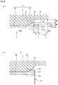
FIG. 4A is a side sectional view illustrating a normal installation state of the seal device in the embodiment, andFIG. 4B is a side sectional view illustrating a state where the seal device has moved to the atmosphere side in the embodiment. -
FIGS. 5A and 5B are front views illustrating modification examples of the holder as seen from the atmosphere side in the embodiment. -
FIGS. 6A to 6C are side sectional views illustrating modification examples of a protruding portion in the embodiment. -
FIGS. 7A and 7B are side sectional views illustrating modification examples of a tapered portion in the embodiment. - Hereinafter, a mode for implementing a seal device according to the present invention will be described based on an embodiment.
- A seal device according to an embodiment will be described with reference to
FIGS. 1 to 7 . - As illustrated in
FIG. 1 , aseal device 10 of the present embodiment is a lip seal device, and is used in a water pump 1, which pressure-feeds cooling water (so-called LLC) that cools an engine of an automobile, to prevent the cooling water inside ahousing 3 from leaking outside. The water pump 1 is configured such that animpeller 21 mounted on the other side end portion of a rotatingshaft 2 is rotated to deliver the cooling water from a discharge port by the rotation of apulley 20 mounted on one side end portion of the rotatingshaft 2. Abearing 22 is mounted on a substantially central portion of the rotatingshaft 2. In addition, theseal device 10 is mounted in a shaft hole H and partitions an interior of thehousing 3 into a sealed fluid side L and an atmosphere side A to seal a space between the rotatingshaft 2 and thehousing 3. Incidentally, theseal device 10 according to the present invention may be applied to other fluids or applications. - Subsequently, the
seal device 10 will be described. As illustrated inFIG. 2 , theseal device 10 is unitized by assembling afirst seal lip 11 as a seal member made of a rubber material, for example, H-NBR and asecond seal lip 12 made of a resin material, for example, PTFE with aninside case 14, abackup ring 15, and anadapter 16 on an inner diameter side of aholder 13 formed into a cylindrical shape. - As illustrated in
FIGS. 2 and3 , a stainless steel is extruded and then pressed to form theholder 13, and theholder 13 includes acylindrical portion 13a which has a plate shape and extends along an axis of theholder 13, abottom plate portion 13b which has an annular shape and is bent from an atmosphere side A end portion of thecylindrical portion 13a toward the inner diameter side of theholder 13 substantially in a vertical direction to protrude linearly, and aprotruding portion 13c which protrudes linearly from a sealed fluid side L end portion of thecylindrical portion 13a toward an outer diameter side thereof substantially in the vertical direction, to form a crank shape in a sectional view. - In addition, the
holder 13 has substantially the same dimension where the outer diameter of thecylindrical portion 13a is slightly larger than the inner diameter of the shaft hole H. In addition, as illustrated in a callout ofFIG. 3 , alatex 19 is applied to an outer peripheral surface of theholder 13. - As illustrated in
FIGS. 2 to 4 , theprotruding portion 13c is formed on an outer peripheral surface of the sealed fluid side L end portion of theholder 13 without interruption in a circumferential direction (refer toFIG. 3 ). A protrusion dimension K1 of theprotruding portion 13c from thecylindrical portion 13a is smaller than a thickness t13a of thecylindrical portion 13a (i.e., K1 < t13a), and a dimension K2 of theprotruding portion 13c in an axial direction is larger than the thickness t13a of thecylindrical portion 13a (i.e., K2 > t13a) (refer toFIG. 4A ). Accordingly, the protrudingportion 13c has a high rigidity in the axial direction, so that theseal device 10 can be assembled to thehousing 3 having a small diameter on the sealed fluid side L. In addition, an angle α of acorner 13d of the protrudingportion 13c, which faces atapered surface 31 of thehousing 3 to be described later, is substantially 90 degrees. In addition, a sealed fluid side L end surface of the protrudingportion 13c is aligned with a sealed fluid side L end surface of thecylindrical portion 13a of theholder 13 in a radial direction, so that the thickness of theholder 13 within the formation range of the protrudingportion 13c becomes thick, and thus the rigidity of theholder 13 is high. Furthermore, since the protrudingportion 13c is formed by forging, the rigidity of the protrudingportion 13c is high. In addition, the protrudingportion 13c is more easily formed, for example, compared to when a protruding portion having the same shape is formed by cutting. In addition, it is preferable that the protrudingportion 13c is harder than thehousing 3. - As illustrated in
FIG. 2 , theinside case 14 is formed into a cylindrical shape from a stainless steel, and has a downward U-shape in a sectional view. Similarly, thebackup ring 15 is formed into a downward L-shaped cylindrical shape in a sectional view, and theadapter 16 is formed into a rightward U-shaped cylindrical shape in a sectional view. - As illustrated in
FIG. 2 , thefirst seal lip 11 is formed into a cylindrical shape, and includes an outerperipheral portion 11a extending along an axis of thefirst seal lip 11, anextension portion 11b extending from a sealed fluid side L end portion of the outerperipheral portion 11a toward an inner diameter side of thefirst seal lip 11 substantially in the vertical direction, and an innerperipheral portion 11c extending obliquely downward from an inner diameter side end portion of theextension portion 11b toward the sealed fluid side L, to form a crank shape in a sectional view. - As illustrated in
FIG. 2 , thesecond seal lip 12 is formed into a cylindrical shape, and includes anextension portion 12b extending substantially in the vertical direction with respect to an axis of thesecond seal lip 12 and an innerperipheral portion 12c which is bent from an inner diameter side end portion of theextension portion 12b toward the sealed fluid side L substantially in the vertical direction to extend along therotating shaft 2, namely, along the axis of thesecond seal lip 12, to form an L-shape in a sectional view. - Subsequently, the
housing 3 will be described. Thehousing 3 is made of a resin material by die cutting, and includes an innerperipheral surface 30 which is linear in a sectional view and communicates with a space on the atmosphere side A, the taperedsurface 31 as a tapered portion which has a linear tapered shape in a sectional view and communicates with the innerperipheral surface 30 and of which the diameter increases gradually toward the sealed fluid side L, aradial end surface 32 extending from a sealed fluid side L end portion of the taperedsurface 31 toward an outer diameter side of thehousing 3 substantially in the vertical direction with respect to the axis of the shaft hole H, and aperipheral end surface 33 extending from an outer diameter side end portion of theradial end surface 32 toward the sealed fluid side L substantially in the vertical direction. The shaft hole H is defined by the innerperipheral surface 30 and the taperedsurface 31, and the taperedsurface 31 forms one end portion of the shaft hole H. - As illustrated in
FIG. 4 , an inclination angle β of the taperedsurface 31 with respect to the axis from the sealed fluid side L to the atmosphere side A is substantially 20 degrees. In addition, a dimension M1 of the taperedsurface 31 in the radial dimension from an atmosphere side A end portion thereof to the sealed fluid side L is larger than the foregoing protrusion dimension K1 of the protrudingportion 13c (i.e., M1 > K1). In other words, an outer diameter of the protrudingportion 13c is smaller than a largest inner diameter of the taperedsurface 31. Incidentally, the inclination angle β of the taperedsurface 31 is not limited to a specific numerical number, and similarly, the following numerical values are not also limited. - As illustrated in
FIGS. 2 and4 , a space on the sealed fluid side L which is adjacent to a shaft hole H side is formed in a substantially columnar space where a radius R33 to theperipheral end surface 33 is slightly larger than a radius R30 of the shaft hole H. Specifically, a dimension M2 of theradial end surface 32 from an inner diameter side to an outer diameter side thereof is substantially the same dimension as the foregoing dimension M1 of the atmosphere side A of the tapered surface 31 (i.e., M1 ≈ M2) in the radial dimension, and the dimension M2 in the radial direction from the sealed fluid side L end portion of the taperedsurface 31 to theperipheral end surface 33 is approximately 1.5 times, preferably 1 to 3 times the thickness t13a of thecylindrical portion 13a of theholder 13. Namely, the space on the sealed fluid side L is formed in a space having a small inner diameter, where there is a slight difference in radial dimension between the space and the shaft hole H or theholder 13. - Subsequently, the assembly of the
seal device 10 to thehousing 3 will be described. In a state where theseal device 10 is positionally aligned with the shaft hole H, when a jig (not illustrated) is engaged with the protrudingportion 13c from the inner diameter side of theholder 13 and theseal device 10 is pushed in together with the jig in the axial direction, firstly, thebottom plate portion 13b is guided by the taperedsurface 31, and the axis of theholder 13 smoothly approaches the axis of the shaft hole H. In addition, since an outer diameter side of thebottom plate portion 13b is bent, thebottom plate portion 13b is smoothly guided and inserted into the shaft hole H. - When the
seal device 10 is further pushed toward the atmosphere side A in the shaft hole H by the jig and thecylindrical portion 13a moves along the innerperipheral surface 30 of thehousing 3 to reach a predetermined position, for example, when thecorner 13d of the protrudingportion 13c reaches a position where thecorner 13d substantially lines up with theradial end surface 32 in the radial direction (refer toFIG. 4A ), the push-in is ended. Accordingly, a majority of thecylindrical portion 13a, namely, 80% or more of thecylindrical portion 13a is fitted into the shaft hole H, and the outer diameter of thecylindrical portion 13a is slightly larger than the inner diameter of the shaft hole H; and thereby, theholder 13 is prevented from being pulled out from the shaft hole H, namely, a fitting force sufficient to immovably fix theholder 13 occurs between thehousing 3 and thecylindrical portion 13a. In this manner, theseal device 10 is fitted into and fixed to thehousing 3, so that both can be assembled. In this case, the protrudingportion 13c of theholder 13 of theseal device 10 is spaced apart from the taperedsurface 31 of thehousing 3 in the axial direction (refer toFIG. 2 ). - In addition, a gap between the
holder 13 and the innerperipheral surface 30 of thehousing 3 is secondarily sealed by thelatex 19 applied to an outer peripheral portion of thecylindrical portion 13a (refer toFIG. 3 ), so that the sealing performance between theseal device 10 and thehousing 3 is improved. - In addition, since the foregoing protrusion dimension K1 of the protruding
portion 13c is shorter than the foregoing dimension M1 of the taperedsurface 31 in the radial dimension, theseal device 10 can be assembled into thehousing 3 having a small inner diameter. Incidentally, theradial end surface 32 may not be provided, so that the inner diameter of the space on the sealed fluid side L is substantially the same dimension as the inner diameter of the sealed fluid side L of the taperedsurface 31. - Here, as described above, normally, the
seal device 10 is immovably fixed by the fitting force occurring between thehousing 3 and thecylindrical portion 13a; however, for example, there may be a case where thehousing 3 is deformed due to aging, a creep deformation, an operating condition where the sealed pressure, the temperature, and the like are severe, or the like, the fitting force between thehousing 3 and theseal device 10 becomes weak, and theseal device 10 moves toward the atmosphere side A due to a pressure on the sealed fluid side L. - When the fitting force between the
housing 3 and theholder 13 becomes weak and theseal device 10 moves toward the atmosphere side A, as illustrated inFIG. 4B , the protrudingportion 13c of theholder 13 of theseal device 10 comes into contact with the taperedsurface 31, so that the movement of theholder 13 is regulated; and thereby, it is possible to prevent theseal device 10 from being pulled out toward the atmosphere side A. - In addition, when the fitting force between the
housing 3 and theholder 13 becomes weak and theseal device 10 moves toward the atmosphere side A, the protrudingportion 13c comes into contact with the taperedsurface 31 to receive a radial force. Therefore, guiding is performed in a state where the axis of theholder 13 coincides with the axis of the shaft hole H, and in a state where the protrudingportion 13c is substantially uniformly pressed toward an inner diameter direction of the taperedsurface 31 to be in uniform contact with the taperedsurface 31 in the circumferential direction, theseal device 10 is pushed in, so that the movement of theseal device 10 is regulated. Accordingly, only a slight movement of theseal device 10 in the axial direction is allowed; and thereby, it is possible to maintain the sealing between thehousing 3 and therotating shaft 2. - In addition, since the
housing 3 and theseal device 10 are assembled in a state where the taperedsurface 31 is spaced apart from the protrudingportion 13c of theholder 13 in the axial direction, until the protrudingportion 13c and the taperedsurface 31 come into contact with each other, no load occurs in the taperedsurface 31 and a creep deformation is unlikely to occur in the taperedsurface 31. Theseal device 10 moves and the protrudingportion 13c of theholder 13 comes into contact with the taperedsurface 31 to easily bite into the taperedsurface 31, so that an excessive movement of theseal device 10 can be reliably prevented; and thereby, it is possible to maintain the sealing performance. - In addition, since the protruding
portion 13c of theholder 13 linearly protrudes from thecylindrical portion 13a of theholder 13 toward the outer diameter side substantially in the vertical direction and the angle of thecorner 13d of the protrudingportion 13c is substantially 90 degrees, the protrudingportion 13c easily bites into the taperedsurface 31; and thereby, it is possible to reduce an excessive positional deviation of theseal device 10 in the axial direction. - In addition, the further the
seal device 10 moves toward the atmosphere side A to cause the protrudingportion 13c of theholder 13 to bite into the taperedsurface 31, the larger the contact area of the taperedsurface 31 with respect to the radial end surface of the protrudingportion 13c of theholder 13 becomes; and thereby, it is possible to increase a force to regulate the movement of theseal device 10. - In addition, since the inclination angle β of the tapered
surface 31 is substantially 20 degrees, namely, is 45 degrees or less, when the protrudingportion 13c of theholder 13 comes into contact with the taperedsurface 31, the taperedsurface 31 acts like a wedge, so that the protrudingportion 13c is unlikely to be pulled out from the taperedsurface 31; and thereby, it is possible to prevent the positional deviation of theseal device 10 in the axial direction. - In addition, since the inclination angle β of the tapered
surface 31 is substantially 20 degrees, the dimension from a portion of the taperedsurface 31 with which the protrudingportion 13c of theholder 13 initially comes into contact to a position where the shaft hole H is reached is large, and thus an allowance of movement to the position where the shaft hole H is reached is large. Therefore, the protrudingportion 13c is unlikely to be pulled out from the taperedsurface 31. - In addition, the
cylindrical portion 13a of theholder 13 comes into contact with thehousing 3 in the circumferential direction, to position theholder 13, and the positioning portion is present only along the circumferential direction; and thereby, it is easy to improve the positioning accuracy. - Subsequently, modification examples of the holder will be described. The mode where the protruding
portion 13c of theholder 13 is formed without interruption in the circumferential direction has been described; however, as illustrated inFIGS. 5A and 5B , a mode where protrudingportions holders - In addition, the mode where the protruding
portion 13c linearly protrudes from thecylindrical portion 13a of theholder 13 toward the outer diameter side substantially in the vertical direction and the angle α of thecorner 13d of the protrudingportion 13c is substantially 90 degrees has been described; however, as illustrated inFIG. 6A , a protrudingportion 313c may include atapered surface 313d which has an inclination angle of substantially 20 degrees and protrudes toward an outer diameter side from the atmosphere side A toward the sealed fluid side L. In this mode, since the inclination angle of the taperedsurface 31 and the inclination angle of the taperedsurface 313d are substantially the same, when aholder 313 moves toward the atmosphere side A, the taperedsurface 313d comes into surface contact with the taperedsurface 31, so that a pressing force which is applied to the protrudingportion 313c from the taperedsurface 31 can be substantially equally dispersed; and thereby, the guide accuracy is high and the position regulating function is very accurate. - In addition, as illustrated in
FIG. 6B , a mode where a protrudingportion 413c protrudes in a hemispherical shape in a sectional view toward an outer diameter side of aholder 413 may be adopted. In this mode, a deformation of the protrudingportion 413c due to coming into contact with the taperedsurface 31 is unlikely to occur. - In addition, as illustrated in
FIG. 6C , a mode where a sealed fluid side L end portion of aholder 513 includes a protrudingportion 513c which linearly protrudes from a cylindrical portion of theholder 513 toward an outer diameter side of theholder 513 substantially in the vertical direction and a recessed portion which is recessed on an inner diameter side of the cylindrical portion from a sealed fluid side L end surface of theholder 513 to a substantially axial central portion of the protrudingportion 513c, to form a step shape in a sectional view may be adopted. In this mode, the weight of theholder 513 is reduced and the production thereof is simple. - Subsequently, modification examples of the tapered portion will be described. The mode where the inclination angle β of the tapered
surface 31 from the atmosphere side A to the sealed fluid side L is substantially 20 degrees has been described; however, as illustrated inFIG. 7A , a mode where the inclination angle of atapered surface 131 as a tapered portion from the atmosphere side A to the sealed fluid side L is substantially 50 degrees, namely, is 45 degrees or greater may be adopted. - In addition, the mode where the tapered
surface 31 has a linear tapered shape in a sectional view has been described; however, as illustrated inFIG. 7B , a mode where atapered surface 231 as a tapered portion is formed into a protrusion-curved tapered shape in a sectional view may be adopted. In this mode, since the inner diameter of a substantially central portion from a sealed fluid side L end portion to an atmosphere side A end portion decreases rapidly, the accuracy of guiding theholder 13 is high and the position regulating function for theholder 13 is very accurate. - In addition, the mode where the tapered
surface 31 is continuous in the circumferential direction has been described; however, as illustrated inFIG. 7C , a mode where taperedsurfaces 331 as tapered portions protruding discontinuously in the circumferential direction are formed at predetermined intervals, such as eight equal intervals or three equal intervals may be adopted. - The embodiment of the present invention has been described above with reference to the drawings; however, the specific configuration is not limited to the embodiment, and changes or additions which are made without departing from the concept of the present invention can be included in the present invention.
- For example, in the foregoing embodiment, a lip seal device has been described as a mode of the
seal device 10; however, the present invention is not limited thereto, and theseal device 10 may be another type of seal device such as a labyrinth seal device or a gland packing seal device. - In addition, the mode where the
seal device 10 is assembled to thehousing 3 having a small inner diameter on the sealed fluid side L has been described; however, the present invention is not limited thereto, and theseal device 10 may be assembled to a housing having a large inner diameter on the sealed fluid side L. In addition, the mode where the housing is made of a resin has been described; however, the present invention is not limited thereto, and the housing may be made of metal such as a stainless steel or an aluminum-steel alloy. - In addition, the mode where when the
seal device 10 is assembled to thehousing 3, the protrudingportion 13c of theholder 13 is spaced apart from the taperedsurface 31 of thehousing 3 in the axial direction has been described; however, the present invention is not limited thereto, and a mode where when theseal device 10 is assembled to thehousing 3, the taperedsurface 31 and the protrudingportion 13c of theholder 13 are in contact with each other may be adopted. -
- 2
- Rotating shaft
- 3
- Housing
- 10
- Seal device
- 11
- First seal lip (seal member)
- 12
- Second seal lip (seal member)
- 13
- Holder
- 13a
- Cylindrical portion
- 13c
- Protruding portion
- 31
- Tapered surface (tapered portion)
- 113
- Holder
- 113c
- Protruding portion
- 131
- Tapered surface (tapered portion)
- 213
- Holder
- 213c
- Protruding portion
- 231
- Tapered surface (tapered portion)
- 313
- Holder
- 313c
- Protruding portion
- 331
- Tapered surface (tapered portion)
- 413
- Holder
- 413c
- Protruding portion
- 513
- Holder
- 513c
- Protruding portion
- A
- Atmosphere side
- H
- Shaft hole
- K1
- Protrusion dimension
- K2
- Dimension
- L
- Sealed fluid side
- M1
- Dimension
- M2
- Dimension
- R30
- Radius
- R33
- Radius
- t13a
- Thickness
- α
- Angle
- β
- Inclination angle
Claims (6)
- A seal device for sealing a space between a housing and a rotating shaft, comprising:a seal member; anda holder having a cylindrical portion and configured to retain the seal member, the cylindrical portion of the holder being press-fitted into a shaft hole provided in a housing,wherein the holder is provided with, at one end of the cylindrical portion, a protruding portion protruded in a radially outward direction of the cylindrical portion,the shaft hole of the housing has a tapered portion having an annular shape and forming one end portion of the shaft hole to guide an insertion of the holder into the shaft hole, andthe protruding portion is provided on an inner diameter side of the tapered portion.
- The seal device according to claim 1,
wherein the protruding portion is spaced apart from an inner surface of the tapered portion in an axial direction in a state where the seal device is assembled to the housing. - The seal device according to claim 1 or 2,
wherein an end surface of the protruding portion and an end surface of the cylindrical portion of the holder in a radial direction coincide with each other. - The seal device according to any one of claims 1 to 3,
wherein a protrusion dimension of the protruding portion from the cylindrical portion of the holder is smaller than a thickness of the cylindrical portion. - The seal device according to any one of claims 1 to 4,
wherein an end portion of the protruding portion, which faces the tapered portion, has a surface extending from the cylindrical portion of the holder substantially in a vertical direction. - The seal device according to any one of claims 1 to 5,
wherein an inclination angle of the tapered portion with respect to the shaft hole is 45 degrees or less.
Applications Claiming Priority (2)
| Application Number | Priority Date | Filing Date | Title |
|---|---|---|---|
| JP2018048435 | 2018-03-15 | ||
| PCT/JP2019/010145 WO2019176976A1 (en) | 2018-03-15 | 2019-03-13 | Seal device |
Publications (2)
| Publication Number | Publication Date |
|---|---|
| EP3767138A1 true EP3767138A1 (en) | 2021-01-20 |
| EP3767138A4 EP3767138A4 (en) | 2022-01-19 |
Family
ID=67906784
Family Applications (1)
| Application Number | Title | Priority Date | Filing Date |
|---|---|---|---|
| EP19767477.3A Pending EP3767138A4 (en) | 2018-03-15 | 2019-03-13 | SEALING DEVICE |
Country Status (5)
| Country | Link |
|---|---|
| US (1) | US11384840B2 (en) |
| EP (1) | EP3767138A4 (en) |
| JP (1) | JP7124057B2 (en) |
| CN (1) | CN111771074A (en) |
| WO (1) | WO2019176976A1 (en) |
Family Cites Families (19)
| Publication number | Priority date | Publication date | Assignee | Title |
|---|---|---|---|---|
| FR1477198A (en) * | 1966-04-25 | 1967-04-14 | Toyo Bearing Mfg Company | Seal for bearings |
| US3467395A (en) | 1966-05-13 | 1969-09-16 | Nippon Seiko Kk | Lubricant seal having casing and its holding means |
| US3741615A (en) | 1971-05-03 | 1973-06-26 | Timken Co | Bearing seal case mounting |
| JPH0670474B2 (en) * | 1987-06-16 | 1994-09-07 | 株式会社荒井製作所 | Peripheral metal fitting type oil seal |
| DE4018216A1 (en) * | 1990-06-07 | 1991-12-12 | Goetze Ag | Shaft sealing ring e.g. of PTFE - seated in interfitting metal housing rings |
| JP2003120823A (en) * | 2001-10-19 | 2003-04-23 | Eagle Ind Co Ltd | Seal device |
| JP4545468B2 (en) * | 2004-03-26 | 2010-09-15 | 光洋シーリングテクノ株式会社 | Sealing device |
| JP2006300186A (en) | 2005-04-19 | 2006-11-02 | Eagle Ind Co Ltd | Shaft sealing device |
| US20090206555A1 (en) * | 2006-07-07 | 2009-08-20 | Eagle Industry Co., Ltd. | Shaft seal apparatus |
| JP3137481U (en) * | 2007-09-14 | 2007-11-22 | イーグル工業株式会社 | Lip type seal mounting structure |
| US8256772B2 (en) * | 2008-11-27 | 2012-09-04 | Eagle Industry Co., Ltd. | Lip type seal |
| US20130228978A1 (en) * | 2011-03-31 | 2013-09-05 | Eagle Industry Co., Ltd. | Sealing device and sealing structure |
| CN104040228B (en) | 2012-06-25 | 2016-10-05 | 伊格尔工业股份有限公司 | Sealing device |
| US9194498B2 (en) * | 2012-08-23 | 2015-11-24 | Eagle Industry Co., Ltd. | Sealing device |
| JP6208665B2 (en) * | 2012-08-23 | 2017-10-04 | イーグル工業株式会社 | Sealing device |
| JP5726345B1 (en) * | 2014-03-24 | 2015-05-27 | 三菱電線工業株式会社 | Shaft seal |
| US10322797B2 (en) | 2015-03-03 | 2019-06-18 | Bell Helicopter Textron Inc. | Rotating sealing systems |
| JP6740734B2 (en) | 2016-06-13 | 2020-08-19 | 株式会社ジェイテクト | Manufacturing method of bearing device for wheel |
| DE102016217069A1 (en) * | 2016-09-08 | 2018-03-08 | Schaeffler Technologies AG & Co. KG | Sealing arrangement of a wheel bearing |
-
2019
- 2019-03-13 US US16/975,688 patent/US11384840B2/en active Active
- 2019-03-13 CN CN201980015696.6A patent/CN111771074A/en active Pending
- 2019-03-13 JP JP2020506580A patent/JP7124057B2/en active Active
- 2019-03-13 WO PCT/JP2019/010145 patent/WO2019176976A1/en not_active Ceased
- 2019-03-13 EP EP19767477.3A patent/EP3767138A4/en active Pending
Also Published As
| Publication number | Publication date |
|---|---|
| CN111771074A (en) | 2020-10-13 |
| US11384840B2 (en) | 2022-07-12 |
| JP7124057B2 (en) | 2022-08-23 |
| EP3767138A4 (en) | 2022-01-19 |
| WO2019176976A1 (en) | 2019-09-19 |
| US20200400235A1 (en) | 2020-12-24 |
| JPWO2019176976A1 (en) | 2021-03-11 |
Similar Documents
| Publication | Publication Date | Title |
|---|---|---|
| EP2275722B1 (en) | Lip type seal | |
| EP3412941B1 (en) | Gasket | |
| EP3505799B1 (en) | Sealing device | |
| JP5288305B2 (en) | Rubber seal fixing device for rolling bearing sealing | |
| US8366117B2 (en) | Sealing device | |
| US6565096B2 (en) | Lip type seal | |
| EP2187102A1 (en) | Installation structure for lip type seal | |
| EP2685140B1 (en) | Sealing device | |
| US9850949B2 (en) | Temperature compensation ring, bearing ring, and bearing assembly | |
| CN108071804B (en) | Seal assembly for rotating member | |
| EP2821661B1 (en) | Sealing device | |
| EP3434943A1 (en) | Sealing device | |
| US11365810B1 (en) | Flooded metallic bearing isolator | |
| EP2740958B1 (en) | Ball bearing | |
| US11384840B2 (en) | Seal device | |
| EP3875810B1 (en) | Sealing device | |
| EP4317750A1 (en) | Sealing structure and sealing method | |
| CN101975298B (en) | Gas bleeder plug, bearing device and bearing | |
| JP2005240932A (en) | Sealing device | |
| EP4534875A1 (en) | Mechanical tool | |
| JP3219517U (en) | Lip seal device | |
| CN101124422B (en) | gas release plug, bearing device and bearing | |
| JP7489816B2 (en) | Sealing device and sealing structure | |
| EP4357645A1 (en) | Sealing device | |
| JP2017129187A (en) | Seal for ball screw and ball screw |
Legal Events
| Date | Code | Title | Description |
|---|---|---|---|
| STAA | Information on the status of an ep patent application or granted ep patent |
Free format text: STATUS: THE INTERNATIONAL PUBLICATION HAS BEEN MADE |
|
| PUAI | Public reference made under article 153(3) epc to a published international application that has entered the european phase |
Free format text: ORIGINAL CODE: 0009012 |
|
| STAA | Information on the status of an ep patent application or granted ep patent |
Free format text: STATUS: REQUEST FOR EXAMINATION WAS MADE |
|
| 17P | Request for examination filed |
Effective date: 20201001 |
|
| AK | Designated contracting states |
Kind code of ref document: A1 Designated state(s): AL AT BE BG CH CY CZ DE DK EE ES FI FR GB GR HR HU IE IS IT LI LT LU LV MC MK MT NL NO PL PT RO RS SE SI SK SM TR |
|
| AX | Request for extension of the european patent |
Extension state: BA ME |
|
| DAV | Request for validation of the european patent (deleted) | ||
| DAX | Request for extension of the european patent (deleted) | ||
| A4 | Supplementary search report drawn up and despatched |
Effective date: 20211220 |
|
| RIC1 | Information provided on ipc code assigned before grant |
Ipc: F16J 15/3252 20160101ALI20211214BHEP Ipc: F16J 15/3232 20160101ALI20211214BHEP Ipc: F16J 15/3268 20160101AFI20211214BHEP |
|
| STAA | Information on the status of an ep patent application or granted ep patent |
Free format text: STATUS: EXAMINATION IS IN PROGRESS |
|
| 17Q | First examination report despatched |
Effective date: 20230718 |