EP3767101A1 - Wind turbine having a hollow, accessible generator shaft - Google Patents
Wind turbine having a hollow, accessible generator shaft Download PDFInfo
- Publication number
- EP3767101A1 EP3767101A1 EP19187016.1A EP19187016A EP3767101A1 EP 3767101 A1 EP3767101 A1 EP 3767101A1 EP 19187016 A EP19187016 A EP 19187016A EP 3767101 A1 EP3767101 A1 EP 3767101A1
- Authority
- EP
- European Patent Office
- Prior art keywords
- wind turbine
- hub
- door
- generator shaft
- safety element
- Prior art date
- Legal status (The legal status is an assumption and is not a legal conclusion. Google has not performed a legal analysis and makes no representation as to the accuracy of the status listed.)
- Granted
Links
Images


Classifications
-
- F—MECHANICAL ENGINEERING; LIGHTING; HEATING; WEAPONS; BLASTING
- F03—MACHINES OR ENGINES FOR LIQUIDS; WIND, SPRING, OR WEIGHT MOTORS; PRODUCING MECHANICAL POWER OR A REACTIVE PROPULSIVE THRUST, NOT OTHERWISE PROVIDED FOR
- F03D—WIND MOTORS
- F03D80/00—Details, components or accessories not provided for in groups F03D1/00 - F03D17/00
- F03D80/50—Maintenance or repair
-
- E—FIXED CONSTRUCTIONS
- E06—DOORS, WINDOWS, SHUTTERS, OR ROLLER BLINDS IN GENERAL; LADDERS
- E06B—FIXED OR MOVABLE CLOSURES FOR OPENINGS IN BUILDINGS, VEHICLES, FENCES OR LIKE ENCLOSURES IN GENERAL, e.g. DOORS, WINDOWS, BLINDS, GATES
- E06B11/00—Means for allowing passage through fences, barriers or the like, e.g. stiles
- E06B11/02—Gates; Doors
- E06B11/04—Gates; Doors characterised by the kind of suspension
-
- F—MECHANICAL ENGINEERING; LIGHTING; HEATING; WEAPONS; BLASTING
- F03—MACHINES OR ENGINES FOR LIQUIDS; WIND, SPRING, OR WEIGHT MOTORS; PRODUCING MECHANICAL POWER OR A REACTIVE PROPULSIVE THRUST, NOT OTHERWISE PROVIDED FOR
- F03D—WIND MOTORS
- F03D1/00—Wind motors with rotation axis substantially parallel to the air flow entering the rotor
- F03D1/06—Rotors
- F03D1/065—Rotors characterised by their construction elements
- F03D1/0658—Arrangements for fixing wind-engaging parts to a hub
-
- F—MECHANICAL ENGINEERING; LIGHTING; HEATING; WEAPONS; BLASTING
- F03—MACHINES OR ENGINES FOR LIQUIDS; WIND, SPRING, OR WEIGHT MOTORS; PRODUCING MECHANICAL POWER OR A REACTIVE PROPULSIVE THRUST, NOT OTHERWISE PROVIDED FOR
- F03D—WIND MOTORS
- F03D80/00—Details, components or accessories not provided for in groups F03D1/00 - F03D17/00
- F03D80/80—Arrangement of components within nacelles or towers
- F03D80/88—Arrangement of components within nacelles or towers of mechanical components
-
- F—MECHANICAL ENGINEERING; LIGHTING; HEATING; WEAPONS; BLASTING
- F03—MACHINES OR ENGINES FOR LIQUIDS; WIND, SPRING, OR WEIGHT MOTORS; PRODUCING MECHANICAL POWER OR A REACTIVE PROPULSIVE THRUST, NOT OTHERWISE PROVIDED FOR
- F03D—WIND MOTORS
- F03D9/00—Adaptations of wind motors for special use; Combinations of wind motors with apparatus driven thereby; Wind motors specially adapted for installation in particular locations
- F03D9/20—Wind motors characterised by the driven apparatus
- F03D9/25—Wind motors characterised by the driven apparatus the apparatus being an electrical generator
-
- F—MECHANICAL ENGINEERING; LIGHTING; HEATING; WEAPONS; BLASTING
- F03—MACHINES OR ENGINES FOR LIQUIDS; WIND, SPRING, OR WEIGHT MOTORS; PRODUCING MECHANICAL POWER OR A REACTIVE PROPULSIVE THRUST, NOT OTHERWISE PROVIDED FOR
- F03D—WIND MOTORS
- F03D1/00—Wind motors with rotation axis substantially parallel to the air flow entering the rotor
- F03D1/06—Rotors
- F03D1/065—Rotors characterised by their construction elements
- F03D1/0691—Rotors characterised by their construction elements of the hub
-
- F—MECHANICAL ENGINEERING; LIGHTING; HEATING; WEAPONS; BLASTING
- F05—INDEXING SCHEMES RELATING TO ENGINES OR PUMPS IN VARIOUS SUBCLASSES OF CLASSES F01-F04
- F05B—INDEXING SCHEME RELATING TO WIND, SPRING, WEIGHT, INERTIA OR LIKE MOTORS, TO MACHINES OR ENGINES FOR LIQUIDS COVERED BY SUBCLASSES F03B, F03D AND F03G
- F05B2240/00—Components
- F05B2240/20—Rotors
- F05B2240/21—Rotors for wind turbines
- F05B2240/221—Rotors for wind turbines with horizontal axis
-
- F—MECHANICAL ENGINEERING; LIGHTING; HEATING; WEAPONS; BLASTING
- F05—INDEXING SCHEMES RELATING TO ENGINES OR PUMPS IN VARIOUS SUBCLASSES OF CLASSES F01-F04
- F05B—INDEXING SCHEME RELATING TO WIND, SPRING, WEIGHT, INERTIA OR LIKE MOTORS, TO MACHINES OR ENGINES FOR LIQUIDS COVERED BY SUBCLASSES F03B, F03D AND F03G
- F05B2240/00—Components
- F05B2240/60—Shafts
- F05B2240/61—Shafts hollow
-
- Y—GENERAL TAGGING OF NEW TECHNOLOGICAL DEVELOPMENTS; GENERAL TAGGING OF CROSS-SECTIONAL TECHNOLOGIES SPANNING OVER SEVERAL SECTIONS OF THE IPC; TECHNICAL SUBJECTS COVERED BY FORMER USPC CROSS-REFERENCE ART COLLECTIONS [XRACs] AND DIGESTS
- Y02—TECHNOLOGIES OR APPLICATIONS FOR MITIGATION OR ADAPTATION AGAINST CLIMATE CHANGE
- Y02E—REDUCTION OF GREENHOUSE GAS [GHG] EMISSIONS, RELATED TO ENERGY GENERATION, TRANSMISSION OR DISTRIBUTION
- Y02E10/00—Energy generation through renewable energy sources
- Y02E10/70—Wind energy
- Y02E10/72—Wind turbines with rotation axis in wind direction
Definitions
- the invention concerns a wind turbine having a hollow, walkable generator shaft of a generator assembly and a hollow hub attached to the generator shaft and having at least two blades attached to it, wherein the hub is enterable from the generator shaft and the wind turbine is stoppable in at least two predetermined maintenance positions of the blades.
- Wind turbines in particular in larger sizes, have become common sources of electrical energy.
- the wind turbine comprises a tower carrying a nacelle, in which a generator of a generator arrangement of the wind turbine may be located.
- Rotational energy for the generator is provided by wind-driven blades connected to a rotor hub of the wind turbine, which, in turn, is fixed to a generator shaft of the generator arrangement.
- Wind turbines with or without a gear box have been proposed.
- predetermined maintenance positions of the blades may comprise positions in which a certain blade points vertically downwards, positions in which a certain blade points vertically upwards and/or a position in which a certain blade points horizontal, either to the left or to the right.
- these definitions provide a total of twelve different maintenance positions of the blades and thus the rotor hub.
- a wind turbine as initially described comprises a safety arrangement, in which a rotatably supported safety element having a door is mounted covering the opening leading from the generator shaft into the hub, wherein a locking arrangement for fixing the safety element in an entering position, in which the door is vertically oriented, is provided.
- the safety element may be turned, if necessary, to fit any of the maintenance positions of the blades and thus the hub.
- the safety element of the safety arrangement covers the opening into the rotor hub, such that protection for service technicians is provided, in particular preventing them from falling into the hub unintentionally.
- a doorway is implemented through which safe entrance into the rotor hub can take place.
- the safety element may be fixed in the entering position, such that unintentional rotation of the safety element, in particular during entering the hub or vice versa, is prevented.
- such a safety measure that can be adjusted to fit the actual maintenance position will both save material and space compared to a fixed solution for each maintenance position.
- Safety for persons working in the wind turbine is advantageously increased.
- the safety element may comprise a fence-like structure, in particular a metal structure, in which the door is provided.
- a metal structure in which the door is provided.
- aluminium or, preferably thin, sheet metal may be used as a material for such a fence-like structure.
- the safety element may be light-weight.
- using metal as a material provides stability, wherein the fence-like or grid-like arrangement reduces the material requirement substantially and provides a good view into the hub from the generator shaft for the service technician.
- the safety element in particular a frame or outer part of the fence-like structure, is rotatably supported using rollers mounted to the generator shaft and/or the hub.
- a circular frame or outer part in particular a metal frame or outer part, may be supported and guided on rollers provided circumferentially around the opening of the hollow generator shaft into the hub.
- the rollers or wheels may comprise a central indentation into which the frame or outer part engages for guiding and supporting the frame or outer part, allowing movement only in a rotational direction.
- the locking arrangement may comprise a locking lever, in particular engaging the frame.
- the locking lever may have a handle to facilitate operation by a service technician.
- the locking arrangement may advantageously be in a locked position during normal operation of the wind turbine, that is, with no maintenance works going on.
- the safety element rotates with the generator shaft and the hub, reducing wear on bearing elements supporting the safety element and the safety element itself, for example reducing wear exerted onto rollers.
- a service technician wants to enter the rotor hub for maintenance, they unlock the locking arrangement, turn the safety element into the entering position, and re-lock the locking arrangement to fix the safety element in its current orientation corresponding to the entering position. They may now safely use the door to enter and subsequently leave the hub.
- the door may comprise a lock controlled by a detection device such that the door only opens when the safety element is in the entering position and/or fixed by the locking arrangement.
- the detection device may comprise a gravity sensor for detecting a predefined orientation of the safety element corresponding to the entering position, in particular having the door in a vertical position, such that the gravity sensor, usually an acceleration sensor, may for example have its measuring direction along a longitudinal axis of the door.
- a fixing sensor may be provided, as in principle known, to detect the locking state of the locking arrangement. It is noted that it is also conceivable to implement such a detection device purely using mechanical means, reducing the complexity of the safety arrangement.
- the detection device is optional. Alternatively e.g. a manual locking mechanism could be used.
- the door may be configured only to be opened towards the inside of the generator shaft. That is, a design may be chosen, in which, for safety reasons, the door can only be opened inwards to the generator shaft.
- the door is spring-loaded towards a closed position of the door.
- a spring-loading mechanism the door will close by itself when a person has passed. Additionally, unnecessary movement of the door during normal operation of the wind turbine, in particular when the safety element rotates with the hub and the generator shaft, may be prevented by such a spring-loading mechanism.
- an additional fixing means or the like may be provided to additionally hold the door in a closed position, for example a magnetic fixing means.
- the safety arrangement may further comprise a climbing means, in particular a ladder, wherein the climbing means and/or the safety element comprise suspension means such that the climbing means may be removably suspended into the hub from the threshold of the door. That is, when the access door provided by the safety element is in the right position, that is, the entering position, a separate ladder or other climbing means may be attached to the rotatable safety element, in particular to its frame, such that the service technician can safely climb into the hub.
- a climbing means in particular a ladder
- the ladder can be a separate component from the frame or integrated with the frame as a fixed component.
- At least one climbing aid may be fixedly installed in the hub.
- Such climbing aids have, for example, been described in EP 2 837 821 A1 regarding a hub accessible from the outside, but may also be used to facilitate maintenance work inside a hub enterable from a hollow generator shaft as well as aiding the service technician in safely entering the hub from the generator shaft.
- the design of the separate climbing means which may be suspendedly arranged at the opening, and the design of climbing aids fixedly installed in the hub may be matched to each other, wherein, in particular, the climbing means may be dimensioned to meet a climbing aid of the hub in a corresponding maintenance position. Additionally, if, for example, in a wind turbine having three blades, one of the blades points vertically upward, the dimensions of the climbing means, in particular the ladder, may also correspond to the distance to the interior hub wall between the two blades pointing diagonally down.
- the safety element may further comprise at least one hold at at least one side of the door, extending into the hub, to further aid climbing into the hub by the service technician and to further increase safety.
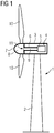
- Fig. 1 shows a principle drawing of a wind turbine 1 according to the current invention.
- the wind turbine 1 comprises a tower 2 carrying a nacelle 3, in which a generator arrangement 4 comprising a generator 5 is housed.
- a hollow generator shaft 6, often also called main shaft, is connected to a rotor hub 7.
- the rotor hub 7 is also hollow such that its interior 8 can be accessed from the interior 9 of the hollow generator shaft 6.
- three blades 10 are attached to the hub 7, from which, in fig. 2 , only two are visible due to perspective.
- a safety arrangement generally indicated at 11 is provided, which is now described in more detail regarding the figures 2 to 5 .
- Fig. 2 shows a view into the interior 8 of the hub 7 in a first maintenance position, wherein a certain one of the blades 10 is in a vertical, upwards pointing orientation.
- the safety arrangement 11 comprises a safety element 12 covering the opening from the generator shaft 6 to the interior 8 of the hub 7, such that a service technician 13 cannot unintentionally fall in.
- the safety element 12 comprises an outer, circular frame 14 made of metal, in particular aluminium or an aluminium alloy or thin sheet metal, which is part of a fence-like structure 15 made of the metal.
- the safety element 12 further comprises a door 16 in the fence-like structure 15.
- the safety element 12 is rotationally supported on the generator shaft 6 by rollers 17.
- a climbing means 18, in this case a ladder, is separately provided and may be suspended from the frame 14 or another part of the fence-like structure 15 using corresponding suspension means before the door 16 is opened.
- the ladder could be integrated with the frame 14 as a fixed component.
- the hub 7 comprises additional climbing aids 19 and the climbing means 18 is dimensioned to directly adjoin the climbing aid 19 when suspended from the frame 14 in the shown maintenance position.
- Fig. 3 shows another maintenance position in which a certain blade points vertically downwards.
- the climbing means 18 ends on top of the interior wall 20 of the hub 7 corresponding to the certain blade 10.
- the safety arrangement 11 further comprises a locking arrangement 21 to fix the rotatably supported safety element 12 in a certain, predefined entering position in which the door 16 is vertically oriented. Further, during normal operation of the wind turbine 1, the safety element 12 is also fixed to the hub 7 and the generator shaft 6 such that it rotates with them. If maintenance is required, once a certain maintenance position is achieved, for example one of the maintenance positions shown in fig. 2 or fig. 3 , the service technician 13 approaches the safety arrangement 11 from inside the hollow generator shaft 6. If the safety element 12, in particular the door 16, is not oriented in the entering position, they may unlock the locking arrangement 21 and rotate the rotatably supported safety element 12 into the entering position, where it can be fixed again using the locking arrangement 21.
- the service technician 13 can now suspend the climbing means 18 into the interior 8 of the hub 7 and open the door 16 to enter, as shown in fig. 3 .
- the door 16 is configured to only open towards the interior 9 of the generator shaft 6.
- the service technician 13 can now safely climb into the interior 8 of the hub 7.
- the locking arrangement 21 comprises locking lever 22 using the excenter principle to fix the rotational position of the safety element 12.
- the rollers 17 comprise indentations in which the frame 14 or outer part of the fence-like structure 15 is guided.
- the frame 14 is, preferably, integral with the fence-like structure 15, as can also be seen in fig. 2 and fig. 3 .
- Fig. 5 illustrates that the door 16 is coupled to the fence-like structure 15 by a spring-loading mechanism 23 using a spring 24 such that the door 16 automatically closes and is kept in a closed position by the corresponding restoring force of the spring 24.
- the safety element 12 may also comprise a lock 25 which is controlled by a detection device 26 such that the door 16 only opens when the safety element 12 is in the entering position.
- the detection device 26 may comprise a gravity sensor 27 (acceleration sensor) to detect a predefined orientation of the safety element 12 corresponding to the entering position.
- the detection device 26 may further comprise a fixing sensor for detecting the locking state of the locking arrangement 21; in this case, the lock 25 only opens if the safety element 12 is in the entering position and fixed in its rotational position by the locking means 21. It would also be possible to not use a lock 25 or to use other means for locking and unlocking the lock 25 then the discussed detection device 26, e.g. a manual lock.
- safety element 12 may also comprise handles or holds 28 at at least one side of the door 16, further simplifying climbing into or out of the hub 7.
Landscapes
- Engineering & Computer Science (AREA)
- Life Sciences & Earth Sciences (AREA)
- Sustainable Development (AREA)
- Sustainable Energy (AREA)
- Chemical & Material Sciences (AREA)
- Combustion & Propulsion (AREA)
- Mechanical Engineering (AREA)
- General Engineering & Computer Science (AREA)
- Power Engineering (AREA)
- Civil Engineering (AREA)
- Structural Engineering (AREA)
- Wind Motors (AREA)
Abstract
Description
- The invention concerns a wind turbine having a hollow, walkable generator shaft of a generator assembly and a hollow hub attached to the generator shaft and having at least two blades attached to it, wherein the hub is enterable from the generator shaft and the wind turbine is stoppable in at least two predetermined maintenance positions of the blades.
- Wind turbines, in particular in larger sizes, have become common sources of electrical energy. Often, the wind turbine comprises a tower carrying a nacelle, in which a generator of a generator arrangement of the wind turbine may be located. Rotational energy for the generator is provided by wind-driven blades connected to a rotor hub of the wind turbine, which, in turn, is fixed to a generator shaft of the generator arrangement. Wind turbines with or without a gear box have been proposed.
- Increasing focus is laid upon the protection of service personnel working in a wind turbine, in particular, since wind turbines increase in size. Wind turbines of a size where it is possible to enter into the hub from a hollow generator shaft have already been proposed. In this case, the safety of technicians who want to enter into the hub has to be ensured, in particular when passing from the hollow generator shaft into the hollow hub. However, to accommodate different service tasks, several possible, predetermined maintenance positions of the blades (stop positions) have to be defined and used. For example, such predetermined maintenance positions may comprise positions in which a certain blade points vertically downwards, positions in which a certain blade points vertically upwards and/or a position in which a certain blade points horizontal, either to the left or to the right. In a wind turbine having three blades, these definitions provide a total of twelve different maintenance positions of the blades and thus the rotor hub.
- Since there is a considerable height difference between the generator shaft and the interior wall of the hub, into which the technician has to enter, safety measures to prevent a service technician from unintentionally falling into the hub would be expedient. These measures should also provide a structure allowing safe entrance into the hub. However, a lot of different predetermined maintenance positions have to be accommodated, resulting in complex constructional approaches.
- It is an object of the current invention to provide safety measures of an easy construction between the rotor hub and the generator shaft, facilitating safe entrance into the hollow hub.
- To achieve this object, according to the current invention, a wind turbine as initially described comprises a safety arrangement, in which a rotatably supported safety element having a door is mounted covering the opening leading from the generator shaft into the hub, wherein a locking arrangement for fixing the safety element in an entering position, in which the door is vertically oriented, is provided.
- It is thus proposed to use a rotatable framework solution at the hub entrance such that, due to the rotatability, the safety element may be turned, if necessary, to fit any of the maintenance positions of the blades and thus the hub. The safety element of the safety arrangement covers the opening into the rotor hub, such that protection for service technicians is provided, in particular preventing them from falling into the hub unintentionally. A doorway is implemented through which safe entrance into the rotor hub can take place. To further increase safety for the service technician, the safety element may be fixed in the entering position, such that unintentional rotation of the safety element, in particular during entering the hub or vice versa, is prevented.
- Advantageously, such a safety measure that can be adjusted to fit the actual maintenance position will both save material and space compared to a fixed solution for each maintenance position. Safety for persons working in the wind turbine is advantageously increased.
- In preferred embodiments, the safety element may comprise a fence-like structure, in particular a metal structure, in which the door is provided. For example, aluminium or, preferably thin, sheet metal may be used as a material for such a fence-like structure. Preferably, as is the case with aluminium or an alloy comprising aluminium or thin sheet metal, the safety element may be light-weight. Additionally, using metal as a material provides stability, wherein the fence-like or grid-like arrangement reduces the material requirement substantially and provides a good view into the hub from the generator shaft for the service technician.
- Preferably, the safety element, in particular a frame or outer part of the fence-like structure, is rotatably supported using rollers mounted to the generator shaft and/or the hub. For example, a circular frame or outer part, in particular a metal frame or outer part, may be supported and guided on rollers provided circumferentially around the opening of the hollow generator shaft into the hub. The rollers or wheels may comprise a central indentation into which the frame or outer part engages for guiding and supporting the frame or outer part, allowing movement only in a rotational direction.
- In advantageous embodiments, the locking arrangement may comprise a locking lever, in particular engaging the frame. The locking lever may have a handle to facilitate operation by a service technician.
- Generally, the locking arrangement may advantageously be in a locked position during normal operation of the wind turbine, that is, with no maintenance works going on. Thus, during normal operation of the wind turbine, the safety element rotates with the generator shaft and the hub, reducing wear on bearing elements supporting the safety element and the safety element itself, for example reducing wear exerted onto rollers. If a service technician wants to enter the rotor hub for maintenance, they unlock the locking arrangement, turn the safety element into the entering position, and re-lock the locking arrangement to fix the safety element in its current orientation corresponding to the entering position. They may now safely use the door to enter and subsequently leave the hub.
- Preferably, the door may comprise a lock controlled by a detection device such that the door only opens when the safety element is in the entering position and/or fixed by the locking arrangement. In this manner, safety may be further increased. For example, the detection device may comprise a gravity sensor for detecting a predefined orientation of the safety element corresponding to the entering position, in particular having the door in a vertical position, such that the gravity sensor, usually an acceleration sensor, may for example have its measuring direction along a longitudinal axis of the door. Regarding the locking arrangement, a fixing sensor may be provided, as in principle known, to detect the locking state of the locking arrangement. It is noted that it is also conceivable to implement such a detection device purely using mechanical means, reducing the complexity of the safety arrangement. The detection device is optional. Alternatively e.g. a manual locking mechanism could be used.
- Advantageously, the door may be configured only to be opened towards the inside of the generator shaft. That is, a design may be chosen, in which, for safety reasons, the door can only be opened inwards to the generator shaft.
- In this respect, it is also advantageous if the door is spring-loaded towards a closed position of the door. Using such a spring-loading mechanism, the door will close by itself when a person has passed. Additionally, unnecessary movement of the door during normal operation of the wind turbine, in particular when the safety element rotates with the hub and the generator shaft, may be prevented by such a spring-loading mechanism. It is noted that, of course, an additional fixing means or the like may be provided to additionally hold the door in a closed position, for example a magnetic fixing means.
- Preferably, the safety arrangement may further comprise a climbing means, in particular a ladder, wherein the climbing means and/or the safety element comprise suspension means such that the climbing means may be removably suspended into the hub from the threshold of the door. That is, when the access door provided by the safety element is in the right position, that is, the entering position, a separate ladder or other climbing means may be attached to the rotatable safety element, in particular to its frame, such that the service technician can safely climb into the hub. Such a climbing means, in particular a ladder, may, for example, be stored in the nacelle and be brought along by the service technician. The ladder can be a separate component from the frame or integrated with the frame as a fixed component.
- Additionally or alternatively, at least one climbing aid may be fixedly installed in the hub. Such climbing aids have, for example, been described in
EP 2 837 821 A1 - In especially preferred embodiments, the design of the separate climbing means, which may be suspendedly arranged at the opening, and the design of climbing aids fixedly installed in the hub may be matched to each other, wherein, in particular, the climbing means may be dimensioned to meet a climbing aid of the hub in a corresponding maintenance position. Additionally, if, for example, in a wind turbine having three blades, one of the blades points vertically upward, the dimensions of the climbing means, in particular the ladder, may also correspond to the distance to the interior hub wall between the two blades pointing diagonally down.
- In embodiments, the safety element may further comprise at least one hold at at least one side of the door, extending into the hub, to further aid climbing into the hub by the service technician and to further increase safety.
- Further details and advantages of the current invention become apparent from the following detailed description of concrete embodiments, taken in conjunction with the drawings, in which:
- Fig. 1
- shows a wind turbine according to the current invention,
- Fig. 2
- is a view into the interior of the hub in a first position of the blades,
- Fig. 3
- is a view into the hub in a second position of the blades,
- Fig. 4
- is a close-up of a portion of a safety arrangement, and
- Fig. 5
- shows a closer view of the safety arrangement in a door area.
-
Fig. 1 shows a principle drawing of a wind turbine 1 according to the current invention. The wind turbine 1 comprises atower 2 carrying a nacelle 3, in which a generator arrangement 4 comprising a generator 5 is housed. Ahollow generator shaft 6, often also called main shaft, is connected to arotor hub 7. Therotor hub 7 is also hollow such that its interior 8 can be accessed from theinterior 9 of thehollow generator shaft 6. In this case, threeblades 10 are attached to thehub 7, from which, infig. 2 , only two are visible due to perspective. - To provide increased safety for a service technician who wants to enter the
hub 7 from thegenerator shaft 6, a safety arrangement generally indicated at 11 is provided, which is now described in more detail regarding thefigures 2 to 5 . -
Fig. 2 shows a view into theinterior 8 of thehub 7 in a first maintenance position, wherein a certain one of theblades 10 is in a vertical, upwards pointing orientation. Thesafety arrangement 11 comprises asafety element 12 covering the opening from thegenerator shaft 6 to theinterior 8 of thehub 7, such that aservice technician 13 cannot unintentionally fall in. Thesafety element 12 comprises an outer,circular frame 14 made of metal, in particular aluminium or an aluminium alloy or thin sheet metal, which is part of a fence-like structure 15 made of the metal. Thesafety element 12 further comprises adoor 16 in the fence-like structure 15. - The
safety element 12 is rotationally supported on thegenerator shaft 6 byrollers 17. - A climbing means 18, in this case a ladder, is separately provided and may be suspended from the
frame 14 or another part of the fence-like structure 15 using corresponding suspension means before thedoor 16 is opened. Alternatively the ladder could be integrated with theframe 14 as a fixed component. - As can be seen, the
hub 7 comprises additional climbing aids 19 and the climbing means 18 is dimensioned to directly adjoin the climbingaid 19 when suspended from theframe 14 in the shown maintenance position. -
Fig. 3 shows another maintenance position in which a certain blade points vertically downwards. In this case, the climbing means 18 ends on top of theinterior wall 20 of thehub 7 corresponding to thecertain blade 10. - The
safety arrangement 11 further comprises a lockingarrangement 21 to fix the rotatably supportedsafety element 12 in a certain, predefined entering position in which thedoor 16 is vertically oriented. Further, during normal operation of the wind turbine 1, thesafety element 12 is also fixed to thehub 7 and thegenerator shaft 6 such that it rotates with them. If maintenance is required, once a certain maintenance position is achieved, for example one of the maintenance positions shown infig. 2 or fig. 3 , theservice technician 13 approaches thesafety arrangement 11 from inside thehollow generator shaft 6. If thesafety element 12, in particular thedoor 16, is not oriented in the entering position, they may unlock the lockingarrangement 21 and rotate the rotatably supportedsafety element 12 into the entering position, where it can be fixed again using the lockingarrangement 21. Theservice technician 13 can now suspend the climbing means 18 into theinterior 8 of thehub 7 and open thedoor 16 to enter, as shown infig. 3 . As can be seen, thedoor 16 is configured to only open towards theinterior 9 of thegenerator shaft 6. Theservice technician 13 can now safely climb into theinterior 8 of thehub 7. - As can be seen from
fig. 4 , the lockingarrangement 21 comprises lockinglever 22 using the excenter principle to fix the rotational position of thesafety element 12. As can also be seen fromfig. 4 , therollers 17 comprise indentations in which theframe 14 or outer part of the fence-like structure 15 is guided. - The
frame 14 is, preferably, integral with the fence-like structure 15, as can also be seen infig. 2 and fig. 3 . -
Fig. 5 illustrates that thedoor 16 is coupled to the fence-like structure 15 by a spring-loading mechanism 23 using aspring 24 such that thedoor 16 automatically closes and is kept in a closed position by the corresponding restoring force of thespring 24. - Optionally, the
safety element 12 may also comprise alock 25 which is controlled by adetection device 26 such that thedoor 16 only opens when thesafety element 12 is in the entering position. In this example, thedetection device 26 may comprise a gravity sensor 27 (acceleration sensor) to detect a predefined orientation of thesafety element 12 corresponding to the entering position. In other embodiments, thedetection device 26 may further comprise a fixing sensor for detecting the locking state of the lockingarrangement 21; in this case, thelock 25 only opens if thesafety element 12 is in the entering position and fixed in its rotational position by the locking means 21. It would also be possible to not use alock 25 or to use other means for locking and unlocking thelock 25 then the discusseddetection device 26, e.g. a manual lock. - It is noted that the
safety element 12 may also comprise handles or holds 28 at at least one side of thedoor 16, further simplifying climbing into or out of thehub 7. - Although the present invention has been described in detail with reference to the preferred embodiment, the present invention is not limited by the disclosed examples from which the skilled person is able to derive other variations without departing from the scope of the invention.
Claims (10)
- Wind turbine (1) having a hollow, walkable generator shaft (6) of a generator assembly (4) and a hollow hub (7) attached to the generator shaft (6) and having at least two blades (10) attached to it, wherein the hub (7) is enterable from the generator shaft (6) and the wind turbine (1) is stoppable in at least two predetermined maintenance positions of the blades (10), characterised in that the wind turbine (1) further comprises a safety arrangement (11), in which a rotatably supported safety element (12) having a door (16) is mounted covering the opening leading from the generator shaft (6) into the hub (7), wherein a locking arrangement (21) for fixing the safety element (12) in an entering position, in which the door (16) is vertically oriented, is provided.
- Wind turbine (1) according to claim 1, characterised in that the safety element (12) comprises a fence-like structure (15), in particular a metal structure (15), in which the door (16) is provided.
- Wind turbine (1) according to claim 1 or 2, characterised in that the safety element (12) is rotatably supported using rollers (17) mounted to the generator shaft (6) and/or the hub (7).
- Wind turbine (1) according to one of the preceding claims, characterised in that the locking arrangement (21) comprises a locking lever (22), in particular engaging the an outer frame (14) of the fence-like structure (15).
- Wind turbine (1) according to one of the preceding claims, characterised in that the door (16) comprises a lock (25) controlled by a detection device (26) such that the door (16) only opens when the safety element (12) is in the entering position and/or fixed by the locking arrangement (21).
- Wind turbine (1) according to claim 5, characterised in that the detection device (26) comprises a gravity sensor (27) for detecting a predefined orientation of the safety element (12) corresponding to the entering position, and/or a fixing sensor for detecting the locking state of the locking arrangement (21).
- Wind turbine (1) according to one of the preceding claims, characterised in that the door (16) is configured only to be opened towards the inside of the generator shaft (6) .
- Wind turbine (1) according to one of the preceding claims, characterised in that the door (16) is spring-loaded towards a closed position of the door (16).
- Wind turbine (1) according to one of the preceding claims, characterised in that the safety arrangement (11) further comprises a climbing means (18), in particular a ladder, wherein the climbing means (18) and/or the safety element (12) comprise suspension means such that the climbing means (18) may be removably suspended into the hub (7) from the threshold of the door (16).
- Wind turbine (1) according to one of the preceding claims, characterised in that at least one climbing aid (19) is fixedly installed in the hub (7).
Priority Applications (4)
| Application Number | Priority Date | Filing Date | Title |
|---|---|---|---|
| DK19187016.1T DK3767101T3 (en) | 2019-07-18 | 2019-07-18 | Wind turbine with a hole, generator shaft available |
| EP19187016.1A EP3767101B1 (en) | 2019-07-18 | 2019-07-18 | Wind turbine having a hollow, accessible generator shaft |
| US16/918,011 US11365724B2 (en) | 2019-07-18 | 2020-07-01 | Wind turbine having a hollow, walkable generator shaft |
| CN202010691660.4A CN112240268B (en) | 2019-07-18 | 2020-07-17 | Wind turbine with hollow walkable generator shaft |
Applications Claiming Priority (1)
| Application Number | Priority Date | Filing Date | Title |
|---|---|---|---|
| EP19187016.1A EP3767101B1 (en) | 2019-07-18 | 2019-07-18 | Wind turbine having a hollow, accessible generator shaft |
Publications (2)
| Publication Number | Publication Date |
|---|---|
| EP3767101A1 true EP3767101A1 (en) | 2021-01-20 |
| EP3767101B1 EP3767101B1 (en) | 2022-06-01 |
Family
ID=67437998
Family Applications (1)
| Application Number | Title | Priority Date | Filing Date |
|---|---|---|---|
| EP19187016.1A Active EP3767101B1 (en) | 2019-07-18 | 2019-07-18 | Wind turbine having a hollow, accessible generator shaft |
Country Status (4)
| Country | Link |
|---|---|
| US (1) | US11365724B2 (en) |
| EP (1) | EP3767101B1 (en) |
| CN (1) | CN112240268B (en) |
| DK (1) | DK3767101T3 (en) |
Citations (4)
| Publication number | Priority date | Publication date | Assignee | Title |
|---|---|---|---|---|
| US6285090B1 (en) * | 1997-03-10 | 2001-09-04 | Jeumont Industrie | Low-speed directly driven wind turbine |
| EP1985846A1 (en) * | 2007-04-27 | 2008-10-29 | Greenergy India Private Limited | Wind turbine |
| US20140050591A1 (en) * | 2012-08-14 | 2014-02-20 | Thorkil Munk-Hansen | Wind turbine |
| EP2837821A1 (en) | 2013-08-14 | 2015-02-18 | Siemens Aktiengesellschaft | Access system for a hub of a wind turbine |
Family Cites Families (9)
| Publication number | Priority date | Publication date | Assignee | Title |
|---|---|---|---|---|
| ES2474595T3 (en) * | 2008-09-30 | 2014-07-09 | Vestas Wind Systems A/S | Service crane for wind turbine |
| US8061999B2 (en) * | 2008-11-21 | 2011-11-22 | General Electric Company | Spinner-less hub access and lifting system for a wind turbine |
| GB2487797A (en) * | 2011-02-07 | 2012-08-08 | Vestas Wind Sys As | Wind turbine rotor service platform |
| EP2505822B1 (en) * | 2011-03-31 | 2015-11-25 | ALSTOM Renewable Technologies | Wind turbine |
| DK2512007T3 (en) * | 2011-04-15 | 2019-09-09 | Siemens Gamesa Renewable Energy As | Accessory for an electric machine |
| EP2662559A1 (en) * | 2012-05-09 | 2013-11-13 | Siemens Aktiengesellschaft | Wind turbine |
| WO2014108216A1 (en) * | 2013-01-10 | 2014-07-17 | Siemens Aktiengesellschaft | Safety device for an operator during the servicing of a hub of a wind turbine |
| CN206290385U (en) * | 2016-12-22 | 2017-06-30 | 北京金风科创风电设备有限公司 | The impeller attending device and wind power generating set of wind power generating set |
| EP3453870B1 (en) * | 2017-09-11 | 2021-04-07 | Siemens Gamesa Renewable Energy A/S | Hub and spinner for a wind turbine |
-
2019
- 2019-07-18 EP EP19187016.1A patent/EP3767101B1/en active Active
- 2019-07-18 DK DK19187016.1T patent/DK3767101T3/en active
-
2020
- 2020-07-01 US US16/918,011 patent/US11365724B2/en active Active
- 2020-07-17 CN CN202010691660.4A patent/CN112240268B/en active Active
Patent Citations (4)
| Publication number | Priority date | Publication date | Assignee | Title |
|---|---|---|---|---|
| US6285090B1 (en) * | 1997-03-10 | 2001-09-04 | Jeumont Industrie | Low-speed directly driven wind turbine |
| EP1985846A1 (en) * | 2007-04-27 | 2008-10-29 | Greenergy India Private Limited | Wind turbine |
| US20140050591A1 (en) * | 2012-08-14 | 2014-02-20 | Thorkil Munk-Hansen | Wind turbine |
| EP2837821A1 (en) | 2013-08-14 | 2015-02-18 | Siemens Aktiengesellschaft | Access system for a hub of a wind turbine |
Also Published As
| Publication number | Publication date |
|---|---|
| DK3767101T3 (en) | 2022-06-20 |
| CN112240268A (en) | 2021-01-19 |
| US20210017964A1 (en) | 2021-01-21 |
| US11365724B2 (en) | 2022-06-21 |
| EP3767101B1 (en) | 2022-06-01 |
| CN112240268B (en) | 2024-08-13 |
Similar Documents
| Publication | Publication Date | Title |
|---|---|---|
| DK1925818T3 (en) | Rotor for a wind power plant with a bulkhead | |
| DK2698529T3 (en) | Windmill | |
| EP3450752B1 (en) | Wind turbine having an access arrangement for a nacelle | |
| US8061999B2 (en) | Spinner-less hub access and lifting system for a wind turbine | |
| US8555555B2 (en) | Automatic retractable hatch guard | |
| US9228562B2 (en) | Convertible wind turbine nacelle cover | |
| EP2402602A2 (en) | Rescue kit for a wind turbine, a wall for a wind turbine, and a portion of a compartment of a wind turbine | |
| DK2552549T3 (en) | Rappelling device | |
| EP2291585B1 (en) | A hub enclosure for a hub of a wind turbine | |
| EP1174381A1 (en) | Lift plant with an high reduced shaft head room | |
| CN206290376U (en) | The platform structure of tower, tower and wind power generating set | |
| US20160102493A1 (en) | Wind turbine and wind turbine tower | |
| WO2011036432A1 (en) | Traffic pole | |
| US20100193293A1 (en) | Under-ground raise, manhole, vault, or man-way safe entry/exit system | |
| EP3767101B1 (en) | Wind turbine having a hollow, accessible generator shaft | |
| KR100661605B1 (en) | Fire emergency escape device of apartment | |
| EP4212723B1 (en) | Safety door assembly | |
| CN103080536A (en) | Wind energy installation working gantry and wind energy installation | |
| CN110407069B (en) | Elevator car structure | |
| ES2912095T3 (en) | Installation of wind turbines with tower bracket | |
| EP3872340B1 (en) | Hub access through nacelle | |
| JP2007187399A (en) | Chimney curing lid structure | |
| KR19980020429U (en) | door | |
| KR20150001771U (en) | Folding type hatch for Gateway |
Legal Events
| Date | Code | Title | Description |
|---|---|---|---|
| PUAI | Public reference made under article 153(3) epc to a published international application that has entered the european phase |
Free format text: ORIGINAL CODE: 0009012 |
|
| STAA | Information on the status of an ep patent application or granted ep patent |
Free format text: STATUS: THE APPLICATION HAS BEEN PUBLISHED |
|
| AK | Designated contracting states |
Kind code of ref document: A1 Designated state(s): AL AT BE BG CH CY CZ DE DK EE ES FI FR GB GR HR HU IE IS IT LI LT LU LV MC MK MT NL NO PL PT RO RS SE SI SK SM TR |
|
| STAA | Information on the status of an ep patent application or granted ep patent |
Free format text: STATUS: REQUEST FOR EXAMINATION WAS MADE |
|
| 17P | Request for examination filed |
Effective date: 20210720 |
|
| RBV | Designated contracting states (corrected) |
Designated state(s): AL AT BE BG CH CY CZ DE DK EE ES FI FR GB GR HR HU IE IS IT LI LT LU LV MC MK MT NL NO PL PT RO RS SE SI SK SM TR |
|
| GRAP | Despatch of communication of intention to grant a patent |
Free format text: ORIGINAL CODE: EPIDOSNIGR1 |
|
| STAA | Information on the status of an ep patent application or granted ep patent |
Free format text: STATUS: GRANT OF PATENT IS INTENDED |
|
| RIC1 | Information provided on ipc code assigned before grant |
Ipc: F03D 80/50 20160101ALI20220107BHEP Ipc: F03D 1/06 20060101AFI20220107BHEP |
|
| INTG | Intention to grant announced |
Effective date: 20220207 |
|
| GRAS | Grant fee paid |
Free format text: ORIGINAL CODE: EPIDOSNIGR3 |
|
| GRAA | (expected) grant |
Free format text: ORIGINAL CODE: 0009210 |
|
| STAA | Information on the status of an ep patent application or granted ep patent |
Free format text: STATUS: THE PATENT HAS BEEN GRANTED |
|
| AK | Designated contracting states |
Kind code of ref document: B1 Designated state(s): AL AT BE BG CH CY CZ DE DK EE ES FI FR GB GR HR HU IE IS IT LI LT LU LV MC MK MT NL NO PL PT RO RS SE SI SK SM TR |
|
| REG | Reference to a national code |
Ref country code: GB Ref legal event code: FG4D |
|
| REG | Reference to a national code |
Ref country code: AT Ref legal event code: REF Ref document number: 1495516 Country of ref document: AT Kind code of ref document: T Effective date: 20220615 Ref country code: CH Ref legal event code: EP Ref country code: DE Ref legal event code: R096 Ref document number: 602019015344 Country of ref document: DE |
|
| REG | Reference to a national code |
Ref country code: DK Ref legal event code: T3 Effective date: 20220616 |
|
| REG | Reference to a national code |
Ref country code: IE Ref legal event code: FG4D |
|
| REG | Reference to a national code |
Ref country code: NL Ref legal event code: FP |
|
| REG | Reference to a national code |
Ref country code: DE Ref legal event code: R082 Ref document number: 602019015344 Country of ref document: DE Representative=s name: SAUTHOFF, KARSTEN, DIPL.-ING. UNIV., DE |
|
| REG | Reference to a national code |
Ref country code: LT Ref legal event code: MG9D |
|
| PG25 | Lapsed in a contracting state [announced via postgrant information from national office to epo] |
Ref country code: SE Free format text: LAPSE BECAUSE OF FAILURE TO SUBMIT A TRANSLATION OF THE DESCRIPTION OR TO PAY THE FEE WITHIN THE PRESCRIBED TIME-LIMIT Effective date: 20220601 Ref country code: NO Free format text: LAPSE BECAUSE OF FAILURE TO SUBMIT A TRANSLATION OF THE DESCRIPTION OR TO PAY THE FEE WITHIN THE PRESCRIBED TIME-LIMIT Effective date: 20220901 Ref country code: LT Free format text: LAPSE BECAUSE OF FAILURE TO SUBMIT A TRANSLATION OF THE DESCRIPTION OR TO PAY THE FEE WITHIN THE PRESCRIBED TIME-LIMIT Effective date: 20220601 Ref country code: HR Free format text: LAPSE BECAUSE OF FAILURE TO SUBMIT A TRANSLATION OF THE DESCRIPTION OR TO PAY THE FEE WITHIN THE PRESCRIBED TIME-LIMIT Effective date: 20220601 Ref country code: GR Free format text: LAPSE BECAUSE OF FAILURE TO SUBMIT A TRANSLATION OF THE DESCRIPTION OR TO PAY THE FEE WITHIN THE PRESCRIBED TIME-LIMIT Effective date: 20220902 Ref country code: FI Free format text: LAPSE BECAUSE OF FAILURE TO SUBMIT A TRANSLATION OF THE DESCRIPTION OR TO PAY THE FEE WITHIN THE PRESCRIBED TIME-LIMIT Effective date: 20220601 Ref country code: BG Free format text: LAPSE BECAUSE OF FAILURE TO SUBMIT A TRANSLATION OF THE DESCRIPTION OR TO PAY THE FEE WITHIN THE PRESCRIBED TIME-LIMIT Effective date: 20220901 |
|
| REG | Reference to a national code |
Ref country code: AT Ref legal event code: MK05 Ref document number: 1495516 Country of ref document: AT Kind code of ref document: T Effective date: 20220601 |
|
| PG25 | Lapsed in a contracting state [announced via postgrant information from national office to epo] |
Ref country code: RS Free format text: LAPSE BECAUSE OF FAILURE TO SUBMIT A TRANSLATION OF THE DESCRIPTION OR TO PAY THE FEE WITHIN THE PRESCRIBED TIME-LIMIT Effective date: 20220601 Ref country code: PL Free format text: LAPSE BECAUSE OF FAILURE TO SUBMIT A TRANSLATION OF THE DESCRIPTION OR TO PAY THE FEE WITHIN THE PRESCRIBED TIME-LIMIT Effective date: 20220601 Ref country code: LV Free format text: LAPSE BECAUSE OF FAILURE TO SUBMIT A TRANSLATION OF THE DESCRIPTION OR TO PAY THE FEE WITHIN THE PRESCRIBED TIME-LIMIT Effective date: 20220601 |
|
| PG25 | Lapsed in a contracting state [announced via postgrant information from national office to epo] |
Ref country code: SM Free format text: LAPSE BECAUSE OF FAILURE TO SUBMIT A TRANSLATION OF THE DESCRIPTION OR TO PAY THE FEE WITHIN THE PRESCRIBED TIME-LIMIT Effective date: 20220601 Ref country code: SK Free format text: LAPSE BECAUSE OF FAILURE TO SUBMIT A TRANSLATION OF THE DESCRIPTION OR TO PAY THE FEE WITHIN THE PRESCRIBED TIME-LIMIT Effective date: 20220601 Ref country code: RO Free format text: LAPSE BECAUSE OF FAILURE TO SUBMIT A TRANSLATION OF THE DESCRIPTION OR TO PAY THE FEE WITHIN THE PRESCRIBED TIME-LIMIT Effective date: 20220601 Ref country code: PT Free format text: LAPSE BECAUSE OF FAILURE TO SUBMIT A TRANSLATION OF THE DESCRIPTION OR TO PAY THE FEE WITHIN THE PRESCRIBED TIME-LIMIT Effective date: 20221003 Ref country code: ES Free format text: LAPSE BECAUSE OF FAILURE TO SUBMIT A TRANSLATION OF THE DESCRIPTION OR TO PAY THE FEE WITHIN THE PRESCRIBED TIME-LIMIT Effective date: 20220601 Ref country code: EE Free format text: LAPSE BECAUSE OF FAILURE TO SUBMIT A TRANSLATION OF THE DESCRIPTION OR TO PAY THE FEE WITHIN THE PRESCRIBED TIME-LIMIT Effective date: 20220601 Ref country code: CZ Free format text: LAPSE BECAUSE OF FAILURE TO SUBMIT A TRANSLATION OF THE DESCRIPTION OR TO PAY THE FEE WITHIN THE PRESCRIBED TIME-LIMIT Effective date: 20220601 Ref country code: AT Free format text: LAPSE BECAUSE OF FAILURE TO SUBMIT A TRANSLATION OF THE DESCRIPTION OR TO PAY THE FEE WITHIN THE PRESCRIBED TIME-LIMIT Effective date: 20220601 |
|
| PG25 | Lapsed in a contracting state [announced via postgrant information from national office to epo] |
Ref country code: MC Free format text: LAPSE BECAUSE OF FAILURE TO SUBMIT A TRANSLATION OF THE DESCRIPTION OR TO PAY THE FEE WITHIN THE PRESCRIBED TIME-LIMIT Effective date: 20220601 Ref country code: IS Free format text: LAPSE BECAUSE OF FAILURE TO SUBMIT A TRANSLATION OF THE DESCRIPTION OR TO PAY THE FEE WITHIN THE PRESCRIBED TIME-LIMIT Effective date: 20221001 |
|
| REG | Reference to a national code |
Ref country code: CH Ref legal event code: PL |
|
| REG | Reference to a national code |
Ref country code: DE Ref legal event code: R097 Ref document number: 602019015344 Country of ref document: DE |
|
| REG | Reference to a national code |
Ref country code: BE Ref legal event code: MM Effective date: 20220731 |
|
| PG25 | Lapsed in a contracting state [announced via postgrant information from national office to epo] |
Ref country code: AL Free format text: LAPSE BECAUSE OF FAILURE TO SUBMIT A TRANSLATION OF THE DESCRIPTION OR TO PAY THE FEE WITHIN THE PRESCRIBED TIME-LIMIT Effective date: 20220601 |
|
| PLBE | No opposition filed within time limit |
Free format text: ORIGINAL CODE: 0009261 |
|
| STAA | Information on the status of an ep patent application or granted ep patent |
Free format text: STATUS: NO OPPOSITION FILED WITHIN TIME LIMIT |
|
| PG25 | Lapsed in a contracting state [announced via postgrant information from national office to epo] |
Ref country code: LU Free format text: LAPSE BECAUSE OF NON-PAYMENT OF DUE FEES Effective date: 20220718 Ref country code: LI Free format text: LAPSE BECAUSE OF NON-PAYMENT OF DUE FEES Effective date: 20220731 Ref country code: CH Free format text: LAPSE BECAUSE OF NON-PAYMENT OF DUE FEES Effective date: 20220731 |
|
| 26N | No opposition filed |
Effective date: 20230302 |
|
| PG25 | Lapsed in a contracting state [announced via postgrant information from national office to epo] |
Ref country code: SI Free format text: LAPSE BECAUSE OF FAILURE TO SUBMIT A TRANSLATION OF THE DESCRIPTION OR TO PAY THE FEE WITHIN THE PRESCRIBED TIME-LIMIT Effective date: 20220601 Ref country code: BE Free format text: LAPSE BECAUSE OF NON-PAYMENT OF DUE FEES Effective date: 20220731 |
|
| PG25 | Lapsed in a contracting state [announced via postgrant information from national office to epo] |
Ref country code: IE Free format text: LAPSE BECAUSE OF NON-PAYMENT OF DUE FEES Effective date: 20220718 |
|
| PG25 | Lapsed in a contracting state [announced via postgrant information from national office to epo] |
Ref country code: IT Free format text: LAPSE BECAUSE OF FAILURE TO SUBMIT A TRANSLATION OF THE DESCRIPTION OR TO PAY THE FEE WITHIN THE PRESCRIBED TIME-LIMIT Effective date: 20220601 |
|
| PG25 | Lapsed in a contracting state [announced via postgrant information from national office to epo] |
Ref country code: MK Free format text: LAPSE BECAUSE OF FAILURE TO SUBMIT A TRANSLATION OF THE DESCRIPTION OR TO PAY THE FEE WITHIN THE PRESCRIBED TIME-LIMIT Effective date: 20220601 Ref country code: CY Free format text: LAPSE BECAUSE OF FAILURE TO SUBMIT A TRANSLATION OF THE DESCRIPTION OR TO PAY THE FEE WITHIN THE PRESCRIBED TIME-LIMIT Effective date: 20220601 |
|
| PG25 | Lapsed in a contracting state [announced via postgrant information from national office to epo] |
Ref country code: HU Free format text: LAPSE BECAUSE OF FAILURE TO SUBMIT A TRANSLATION OF THE DESCRIPTION OR TO PAY THE FEE WITHIN THE PRESCRIBED TIME-LIMIT; INVALID AB INITIO Effective date: 20190718 |
|
| PG25 | Lapsed in a contracting state [announced via postgrant information from national office to epo] |
Ref country code: TR Free format text: LAPSE BECAUSE OF FAILURE TO SUBMIT A TRANSLATION OF THE DESCRIPTION OR TO PAY THE FEE WITHIN THE PRESCRIBED TIME-LIMIT Effective date: 20220601 |
|
| PG25 | Lapsed in a contracting state [announced via postgrant information from national office to epo] |
Ref country code: MT Free format text: LAPSE BECAUSE OF FAILURE TO SUBMIT A TRANSLATION OF THE DESCRIPTION OR TO PAY THE FEE WITHIN THE PRESCRIBED TIME-LIMIT Effective date: 20220601 |
|
| PG25 | Lapsed in a contracting state [announced via postgrant information from national office to epo] |
Ref country code: BG Free format text: LAPSE BECAUSE OF FAILURE TO SUBMIT A TRANSLATION OF THE DESCRIPTION OR TO PAY THE FEE WITHIN THE PRESCRIBED TIME-LIMIT Effective date: 20220601 |
|
| PG25 | Lapsed in a contracting state [announced via postgrant information from national office to epo] |
Ref country code: BG Free format text: LAPSE BECAUSE OF FAILURE TO SUBMIT A TRANSLATION OF THE DESCRIPTION OR TO PAY THE FEE WITHIN THE PRESCRIBED TIME-LIMIT Effective date: 20220601 |
|
| PGFP | Annual fee paid to national office [announced via postgrant information from national office to epo] |
Ref country code: NL Payment date: 20250724 Year of fee payment: 7 |
|
| PGFP | Annual fee paid to national office [announced via postgrant information from national office to epo] |
Ref country code: DE Payment date: 20250728 Year of fee payment: 7 Ref country code: DK Payment date: 20250725 Year of fee payment: 7 |
|
| PGFP | Annual fee paid to national office [announced via postgrant information from national office to epo] |
Ref country code: GB Payment date: 20250722 Year of fee payment: 7 |
|
| PGFP | Annual fee paid to national office [announced via postgrant information from national office to epo] |
Ref country code: FR Payment date: 20250725 Year of fee payment: 7 |