EP3767097A1 - Engine intake system control device and control method thereof - Google Patents
Engine intake system control device and control method thereof Download PDFInfo
- Publication number
- EP3767097A1 EP3767097A1 EP20185929.5A EP20185929A EP3767097A1 EP 3767097 A1 EP3767097 A1 EP 3767097A1 EP 20185929 A EP20185929 A EP 20185929A EP 3767097 A1 EP3767097 A1 EP 3767097A1
- Authority
- EP
- European Patent Office
- Prior art keywords
- engine
- intake system
- fuel injection
- control device
- gain
- Prior art date
- Legal status (The legal status is an assumption and is not a legal conclusion. Google has not performed a legal analysis and makes no representation as to the accuracy of the status listed.)
- Pending
Links
Images


Classifications
-
- F—MECHANICAL ENGINEERING; LIGHTING; HEATING; WEAPONS; BLASTING
- F02—COMBUSTION ENGINES; HOT-GAS OR COMBUSTION-PRODUCT ENGINE PLANTS
- F02D—CONTROLLING COMBUSTION ENGINES
- F02D41/00—Electrical control of supply of combustible mixture or its constituents
- F02D41/0002—Controlling intake air
- F02D41/0007—Controlling intake air for control of turbo-charged or super-charged engines
-
- F—MECHANICAL ENGINEERING; LIGHTING; HEATING; WEAPONS; BLASTING
- F02—COMBUSTION ENGINES; HOT-GAS OR COMBUSTION-PRODUCT ENGINE PLANTS
- F02B—INTERNAL-COMBUSTION PISTON ENGINES; COMBUSTION ENGINES IN GENERAL
- F02B37/00—Engines characterised by provision of pumps driven at least for part of the time by exhaust
- F02B37/12—Control of the pumps
- F02B37/16—Control of the pumps by bypassing charging air
- F02B37/162—Control of the pumps by bypassing charging air by bypassing, e.g. partially, intake air from pump inlet to pump outlet
-
- F—MECHANICAL ENGINEERING; LIGHTING; HEATING; WEAPONS; BLASTING
- F02—COMBUSTION ENGINES; HOT-GAS OR COMBUSTION-PRODUCT ENGINE PLANTS
- F02B—INTERNAL-COMBUSTION PISTON ENGINES; COMBUSTION ENGINES IN GENERAL
- F02B37/00—Engines characterised by provision of pumps driven at least for part of the time by exhaust
- F02B37/12—Control of the pumps
- F02B37/18—Control of the pumps by bypassing exhaust from the inlet to the outlet of turbine or to the atmosphere
-
- F—MECHANICAL ENGINEERING; LIGHTING; HEATING; WEAPONS; BLASTING
- F02—COMBUSTION ENGINES; HOT-GAS OR COMBUSTION-PRODUCT ENGINE PLANTS
- F02B—INTERNAL-COMBUSTION PISTON ENGINES; COMBUSTION ENGINES IN GENERAL
- F02B37/00—Engines characterised by provision of pumps driven at least for part of the time by exhaust
- F02B37/12—Control of the pumps
- F02B37/24—Control of the pumps by using pumps or turbines with adjustable guide vanes
-
- F—MECHANICAL ENGINEERING; LIGHTING; HEATING; WEAPONS; BLASTING
- F02—COMBUSTION ENGINES; HOT-GAS OR COMBUSTION-PRODUCT ENGINE PLANTS
- F02D—CONTROLLING COMBUSTION ENGINES
- F02D41/00—Electrical control of supply of combustible mixture or its constituents
- F02D41/02—Circuit arrangements for generating control signals
- F02D41/14—Introducing closed-loop corrections
- F02D41/1401—Introducing closed-loop corrections characterised by the control or regulation method
-
- F—MECHANICAL ENGINEERING; LIGHTING; HEATING; WEAPONS; BLASTING
- F02—COMBUSTION ENGINES; HOT-GAS OR COMBUSTION-PRODUCT ENGINE PLANTS
- F02D—CONTROLLING COMBUSTION ENGINES
- F02D41/00—Electrical control of supply of combustible mixture or its constituents
- F02D41/02—Circuit arrangements for generating control signals
- F02D41/18—Circuit arrangements for generating control signals by measuring intake air flow
-
- F—MECHANICAL ENGINEERING; LIGHTING; HEATING; WEAPONS; BLASTING
- F02—COMBUSTION ENGINES; HOT-GAS OR COMBUSTION-PRODUCT ENGINE PLANTS
- F02D—CONTROLLING COMBUSTION ENGINES
- F02D41/00—Electrical control of supply of combustible mixture or its constituents
- F02D41/24—Electrical control of supply of combustible mixture or its constituents characterised by the use of digital means
- F02D41/2406—Electrical control of supply of combustible mixture or its constituents characterised by the use of digital means using essentially read only memories
- F02D41/2425—Particular ways of programming the data
- F02D41/2429—Methods of calibrating or learning
- F02D41/2451—Methods of calibrating or learning characterised by what is learned or calibrated
-
- F—MECHANICAL ENGINEERING; LIGHTING; HEATING; WEAPONS; BLASTING
- F02—COMBUSTION ENGINES; HOT-GAS OR COMBUSTION-PRODUCT ENGINE PLANTS
- F02B—INTERNAL-COMBUSTION PISTON ENGINES; COMBUSTION ENGINES IN GENERAL
- F02B29/00—Engines characterised by provision for charging or scavenging not provided for in groups F02B25/00, F02B27/00 or F02B33/00 - F02B39/00; Details thereof
- F02B29/04—Cooling of air intake supply
-
- F—MECHANICAL ENGINEERING; LIGHTING; HEATING; WEAPONS; BLASTING
- F02—COMBUSTION ENGINES; HOT-GAS OR COMBUSTION-PRODUCT ENGINE PLANTS
- F02D—CONTROLLING COMBUSTION ENGINES
- F02D41/00—Electrical control of supply of combustible mixture or its constituents
- F02D41/02—Circuit arrangements for generating control signals
- F02D41/14—Introducing closed-loop corrections
- F02D41/1401—Introducing closed-loop corrections characterised by the control or regulation method
- F02D2041/1409—Introducing closed-loop corrections characterised by the control or regulation method using at least a proportional, integral or derivative controller
-
- F—MECHANICAL ENGINEERING; LIGHTING; HEATING; WEAPONS; BLASTING
- F02—COMBUSTION ENGINES; HOT-GAS OR COMBUSTION-PRODUCT ENGINE PLANTS
- F02D—CONTROLLING COMBUSTION ENGINES
- F02D41/00—Electrical control of supply of combustible mixture or its constituents
- F02D41/02—Circuit arrangements for generating control signals
- F02D41/14—Introducing closed-loop corrections
- F02D41/1401—Introducing closed-loop corrections characterised by the control or regulation method
- F02D2041/1413—Controller structures or design
- F02D2041/1422—Variable gain or coefficients
-
- F—MECHANICAL ENGINEERING; LIGHTING; HEATING; WEAPONS; BLASTING
- F02—COMBUSTION ENGINES; HOT-GAS OR COMBUSTION-PRODUCT ENGINE PLANTS
- F02D—CONTROLLING COMBUSTION ENGINES
- F02D41/00—Electrical control of supply of combustible mixture or its constituents
- F02D41/02—Circuit arrangements for generating control signals
- F02D41/14—Introducing closed-loop corrections
- F02D41/1401—Introducing closed-loop corrections characterised by the control or regulation method
- F02D2041/1413—Controller structures or design
- F02D2041/1423—Identification of model or controller parameters
-
- F—MECHANICAL ENGINEERING; LIGHTING; HEATING; WEAPONS; BLASTING
- F02—COMBUSTION ENGINES; HOT-GAS OR COMBUSTION-PRODUCT ENGINE PLANTS
- F02D—CONTROLLING COMBUSTION ENGINES
- F02D2200/00—Input parameters for engine control
- F02D2200/02—Input parameters for engine control the parameters being related to the engine
- F02D2200/04—Engine intake system parameters
- F02D2200/0414—Air temperature
-
- F—MECHANICAL ENGINEERING; LIGHTING; HEATING; WEAPONS; BLASTING
- F02—COMBUSTION ENGINES; HOT-GAS OR COMBUSTION-PRODUCT ENGINE PLANTS
- F02D—CONTROLLING COMBUSTION ENGINES
- F02D2200/00—Input parameters for engine control
- F02D2200/02—Input parameters for engine control the parameters being related to the engine
- F02D2200/06—Fuel or fuel supply system parameters
- F02D2200/0602—Fuel pressure
-
- F—MECHANICAL ENGINEERING; LIGHTING; HEATING; WEAPONS; BLASTING
- F02—COMBUSTION ENGINES; HOT-GAS OR COMBUSTION-PRODUCT ENGINE PLANTS
- F02D—CONTROLLING COMBUSTION ENGINES
- F02D2200/00—Input parameters for engine control
- F02D2200/02—Input parameters for engine control the parameters being related to the engine
- F02D2200/10—Parameters related to the engine output, e.g. engine torque or engine speed
- F02D2200/101—Engine speed
-
- F—MECHANICAL ENGINEERING; LIGHTING; HEATING; WEAPONS; BLASTING
- F02—COMBUSTION ENGINES; HOT-GAS OR COMBUSTION-PRODUCT ENGINE PLANTS
- F02D—CONTROLLING COMBUSTION ENGINES
- F02D41/00—Electrical control of supply of combustible mixture or its constituents
- F02D41/0025—Controlling engines characterised by use of non-liquid fuels, pluralities of fuels, or non-fuel substances added to the combustible mixtures
- F02D41/0047—Controlling exhaust gas recirculation [EGR]
- F02D41/005—Controlling exhaust gas recirculation [EGR] according to engine operating conditions
- F02D41/0052—Feedback control of engine parameters, e.g. for control of air/fuel ratio or intake air amount
-
- Y—GENERAL TAGGING OF NEW TECHNOLOGICAL DEVELOPMENTS; GENERAL TAGGING OF CROSS-SECTIONAL TECHNOLOGIES SPANNING OVER SEVERAL SECTIONS OF THE IPC; TECHNICAL SUBJECTS COVERED BY FORMER USPC CROSS-REFERENCE ART COLLECTIONS [XRACs] AND DIGESTS
- Y02—TECHNOLOGIES OR APPLICATIONS FOR MITIGATION OR ADAPTATION AGAINST CLIMATE CHANGE
- Y02T—CLIMATE CHANGE MITIGATION TECHNOLOGIES RELATED TO TRANSPORTATION
- Y02T10/00—Road transport of goods or passengers
- Y02T10/10—Internal combustion engine [ICE] based vehicles
- Y02T10/12—Improving ICE efficiencies
Definitions
- the present invention relates to an engine intake system control device and a control method thereof.
- An engine is used in a gasoline engine or a diesel engine of an automobile.
- an engine system that is a control subject exhibits strong nonlinearity, meaning that normal linear control such as proportional-integral-differential control (PID control) is not able to provide an appropriate control.
- PID control proportional-integral-differential control
- Gain scheduling control in which the optimum control corresponding to the status of the control subject is performed, is often employed.
- Gain scheduling control is also known as variable-parameter PID control since the PID gains that are the parameters of the PID control are modified according to the status of the control subject.
- the control parameters since the control parameters are modified in accordance with the status of the control subject, it is important to select factors to be used to determine the status of the control subject.
- the values of the control parameters normally generate a map function in response to input factors.
- Non Patent Literature 1 Z. Yang, E. Winward, D. Zhao, R. Stobart: Three-Input-Three-Output Air Path Control System of a Heavy-Duty Diesel Engine, Proc. of 8th IFAC International Symposium on Advances in Automotive Control. pp. 616-622. (2016 ).
- an object of a first aspect of this embodiment is to provide an engine intake system control device and a control method thereof, with which PID gains are generated for different statuses.
- an engine intake system control device configured to control an intake system of an engine, has a map function that inputs at least a fuel injection pressure of the engine, a fresh air flow, and a compressor outlet temperature of a supercharger, and outputs a control gain; and a control unit that inputs the control gain and a deviation between a controlled variable of the intake system of the engine and a target value of the intake system, and controls a manipulated variable of the intake system of the engine.
- FIG. 1 is a view illustrating an example configuration of an engine that is a control subject of a control device according to this embodiment.
- the engine illustrated in FIG. 1 is a gasoline engine or a diesel engine used in an automobile, for example.
- the engine includes four cylinders CYL for an internal combustion engine, injectors INJCT attached to the cylinders, an intake manifold IMF for supplying air to the cylinders, and an exhaust manifold EMF for outputting exhaust gas from the cylinders.
- the injectors INJCT of the cylinders inject fuel into the cylinders, and may be provided with a sensor for measuring a fuel injection pressure INJ_P.
- the engine further includes an intake port 11 that suctions air from the outside, a supercharger SPC that compresses a flow of fresh air taken in thereby using the exhaust gas from the exhaust manifold EMF, an air supply passage 1 for supplying the air compressed by the supercharger to the intake manifold IMF, an intercooler 3 provided in the air supply passage 1, and a throttle valve 7 for controlling the quantity of air supplied to the IMF.
- the engine also includes an exhaust gas recirculation (EGR) device provided between the EMF and the IMF, and the EGR device is provided with an EGR cooler 4 for reducing the temperature of the exhaust gas and an EGR valve 6 for adjusting the quantity of recirculated exhaust gas.
- EGR exhaust gas recirculation
- the supercharger SPC is provided in an intake system 10 of the engine.
- the supercharger SPC includes a turbine 13 that is rotated by the exhaust gas, a compressor 12 that is rotated by the rotation of the turbine so as to compress the fresh air flow, and a turbine bypass valve BYP_V provided between the exhaust manifold EMF and an exhaust passage 2. Further, a turbine vane TRB_B having an adjustable opening degree is provided in the turbine 13. A turbine in which the turbine vane opening degree is controlled variably is known as a variable nozzle turbine.
- a sensor for measuring a fresh air flow NAF_Q, a sensor for measuring a supercharging pressure SPC_P, and a sensor for measuring an outlet temperature SPC_Tout of the compressor 12 of the supercharger SPC are provided in the intake system 10.
- An excess air ratio detector 9 is provided in the exhaust passage 2, and an exhaust gas aftertreatment device 5 is provided between the exhaust passage 2 and an exhaust port 8.
- the opening degree of the turbine vane (the turbine vane opening degree) TRB_B and the opening degree of the bypass valve (the bypass valve opening degree) BYP_V are used as actuators of the supercharger SPC of the intake system 10. Further, the opening degree of the EGR valve 6 controls the quantity of exhaust gas used to rotate the turbine and therefore also serves as an actuator.
- FIG. 2 is a view illustrating an example configuration of an engine intake system control device having map functions for computing PID gains on the basis of an engine rotation number RT_N and a fuel injection quantity F_INJ_Q.
- the engine intake system control device of FIG. 2 includes map functions MF_1, MF_2, MF_3 that respectively inputs the engine rotation number RT_N, the fuel injection quantity F_INJ_Q, and another factor, and output PID gains K p , K i , K d .
- the engine intake system control device further includes a supercharger controller CNT that inputs a deviation err between a supercharging pressure SPC_R_y, which is the controlled variable of the intake system of the engine, and a target value SPC_P_r thereof and the PID gains K p , K i , K d , which are control gains output by the map functions, and controls the turbine vane opening degree TRB_B_u.
- the supercharger controller CNT is a PID controller, for example, that computes the turbine vane opening degree TRB_B_u, which is a manipulated variable, with respect to the deviation err on the basis of the PID gains K p , K i , K d .
- the turbine vane opening degree TRB_B_u is one of the manipulated variables of the intake system of the engine.
- the engine intake system control device includes the map functions MF_1, MF_2, MF_3 and the supercharger controller CNT, as described above, and a subtractor SUB for determining a difference between the supercharging pressure SPC_P_y and the target value SPC_P_r thereof.
- the engine intake system control device controls the turbine vane opening degree, which is one of the manipulated variables of the supercharger of the engine ENG, in response to variation in the target value of the supercharging pressure SPC_P_r.
- the map functions MF_1, MF_2, MF_3 compute the PID gains K p , K i , K d of the PID controller CNT in response to input of the engine rotation number RT_N, the fuel injection quantity F_INJ_Q, and the other factor, i.e. parameters indicating the status of the engine.
- the controller CNT of the engine intake system control device then variably controls the turbine vane opening degree TRB_B_u that is a manipulated variable on the basis of the PID gains and the deviation e rr between the target value of the controlled variable and a measured value of the controlled variable of the engine.
- the map functions MF_1, MF_2, MF_3 respectively inputs the engine rotation number RT_N, the fuel injection quantity F_INJ_Q, and another factor, and output the PID gains K p , K i , K d , the PID gains output by the map functions may not match ideal PID gains corresponding to different control statuses. The reason for this is as follows.
- FIG. 3 is a view depicting a flowchart of procedures for designing map functions.
- the three map functions MF_1, MF_2, MF_3 are tables on which the PID gains K p , K i , K d are respectively given in relation to a plurality of combinations of the engine rotation number RT_N, the fuel injection quantity F_INJ_Q, and the other factor.
- the process for designing the map functions includes processing steps S11 to S17 executed in relation to a plurality of combinations (S10, S18) of the engine rotation number RT_N, the fuel injection quantity F_INJ_Q, and the other factor that are the inputs of the map functions.
- an actual engine is operated and the engine rotation number RT_N, the fuel injection quantity F_INJ_Q, and the other factor are fixed at one of a plurality of combinations (S11).
- variation occurring in the controlled variable (the supercharging pressure SPC_P_y) in response to variation in the manipulated variable (the turbine vane opening degree TRB_B_u) is recorded, and a transfer function of the intake system of the engine, which is the controlled device, is computed.
- a variation pattern of the manipulated variable is a variation pattern in which the turbine vane opening degree is varied from a certain value to a different value. More specifically, when designing the map functions, processing steps S13 to S15 are executed on a plurality of variation patterns (S12, S16) of the manipulated variable.
- variation occurring in the controlled variable that is the output of the controlled device (the intake system of the engine) when the manipulated variable that is the input is varied according to a predetermined variation pattern is recorded (S13). At this time, related physical quantity data may also be gathered.
- the transfer function of the intake system of the engine i.e. the model
- the transfer function includes a time constant T, a gain K, a time lag L, and so on.
- the ideal PID gains K p , K i , K d with which to vary the supercharging pressure SPC_P_y that is the controlled variable appropriately to the target value of the supercharging pressure SPC_P_r are computed (S15).
- the ideal PID gains are control parameter values for varying the manipulated variable so that the controlled variable approaches the target value of the controlled variable without overshooting and without excessive delay during evaluation in a control simulation executed on paper, for example, by employing the transfer function as a virtual control subject and connecting the transfer function to a PID control-based controller.
- the processing steps S13 to S15 described above are performed for all variation patterns of the manipulated variable.
- map functions Mf_p, Mf_i, Mf_k for respectively outputting the ideal PID gains computed from the engine rotation number RT_N and the fuel injection quantity F_INJ_Q are created (S17).
- the processing steps S11 to S17 described above are executed for all combinations of the engine rotation number and the fuel injection quantity (S18).
- the engine rotation number and the fuel injection quantity are commonly considered to be physical quantities from which to ascertain the status of the engine. Hence, the engine rotation number and the fuel injection quantity are used as the inputs (factors) of the map functions for outputting the optimum PID gains in accordance with the status of the engine illustrated in FIG. 2 .
- the map functions cannot output ideal PID gains corresponding to the status of the intake system of the engine.
- the engine rotation number and the fuel injection quantity are fixed at predetermined values during the map function design process described above, different ideal PID gains are computed for each of the plurality of variation patterns of the manipulated variable (the turbine vane opening degree).
- the map functions cannot output a plurality of ideal PID gains corresponding to a plurality of variation patterns of the manipulated variable in relation to an engine rotation number and a fuel injection quantity set at certain predetermined values.
- the map functions are designed so as to output average values or the like of a plurality of ideal PID gains in response to the input of predetermined values of the engine rotation number and the fuel injection quantity. Therefore, the designed map functions cannot output ideal PID gains for each of a plurality of statuses of the engine intake system that is the control subject.
- FIG. 4 is a view illustrating examples of ideal PID gains for six variation patterns of the manipulated variable with respect to each of two combinations of the engine rotation number and the fuel injection quantity, determined by the present inventors through experiment.
- FIG. 5 is a view illustrating the map function Mf_p when designed on the basis of the experiment illustrated in FIG. 4 .
- the position of the ideal PID gain K p relative to each combination of the inputs (the engine rotation number RT_N and the fuel injection quantity F_INJ_Q) of the map function Mf_p is plotted on FIG. 5 using points.
- a plurality of ideal PID gains K p exist in a dispersed fashion relative to several combinations of the engine rotation number RT_N and the fuel injection quantity F_INJ_Q.
- the ideal PID gain K p is widely dispersed at condition points of the engine rotation number and the fuel injection quantity.
- vertical arrows indicate this dispersion.
- the map function cannot output an ideal PID gain corresponding to the status.
- FIG. 6 is a view illustrating an engine intake system control device according to this embodiment, which includes map functions for computing PID gains on the basis of the fresh air flow NAF_Q input into the supercharger, the compressor outlet temperature SPC_Tout of the supercharger, and the fuel injection pressure F_INJ_P of the engine.
- the engine intake system control device of FIG. 6 includes map functions MF_1, MF_2, MF_3 that respectively inputs the fresh air flow NAF_Q, the compressor outlet temperature SPC_Tout of the supercharger, and the fuel injection pressure F_INJ_P of the engine and output PID gains K p , K i , K d .
- the engine intake system control device further includes the supercharger controller CNT for computing the turbine vane opening degree TRB_B_u, which is one of the manipulated variables of the intake system of the engine ENG, using, as input, the deviation err between the supercharging pressure SPC_R_y, which is the controlled variable of the intake system of the engine, and the target value SPC_P_r of the supercharging pressure and the PID gains K p , K i , K d , which are the control gains output by the map functions.
- the supercharger controller CNT for computing the turbine vane opening degree TRB_B_u, which is one of the manipulated variables of the intake system of the engine ENG, using, as input, the deviation err between the supercharging pressure SPC_R_y, which is the controlled variable of the intake system of the engine, and the target value SPC_P_r of the supercharging pressure and the PID gains K p , K i , K d , which are the control gains output by the map
- the supercharger controller CNT is a PID controller that computes the turbine vane opening degree TRB_B_u that is the manipulated variable with respect to the deviation err on the basis of the PID gains K p , K i , K d output by the map functions.
- the fresh air flow NAF_Q of the supercharger, the compressor outlet temperature SPC_Tout, and the fuel injection pressure F_INJ_P of the engine take six sets of different values, namely M_af1, T_comp1, R_P1 to M_af6, T_comp6, R_P6 and M_af7, T_comp7, R_P7 to M_af12, T_comp12, R_P12.
- the present inventors randomly modified combinations of a plurality of physical quantities of the engine, designed map functions that inputs the respective combinations and output ideal PID gains for the respective variation patterns of the manipulated variable, and evaluated the respective map functions.
- the manipulated variable of the supercharger of the engine that is the controlled device is the vane opening degree (the turbine vane opening degree) of a variable nozzle turbine
- the controlled variable is the output air pressure of the compressor, i.e. the supercharging pressure.
- a combination of the fresh air flow NAF_Q of the supercharger, the compressor outlet temperature SPC_Tout, and the fuel injection pressure F_INJ_P of the engine is employed as the combination of physical quantities that are the input of the map functions.
- the map functions Mf_p, Mf_i, Mf_d can output ideal PID gains that are suitable for the status of the supercharger and correspond to a plurality of variation patterns of the manipulated variable.
- the engine intake system control device illustrated in FIG. 6 includes a first map function Mf_1 that computes a proportional gain K p as a first control gain from information about the fuel injection pressure, the fresh air flow, and the compressor output temperature, a second map function Mf_2 that computes an integral gain K i as a second control gain from the information about the fuel injection pressure, the fresh air flow, and the compressor output temperature, and a third map function Mf_3 that computes a differential gain K d as a third control gain from the information about the fuel injection pressure, the fresh air flow, and the compressor output temperature.
- Each map function is either a three-dimensionally structured map or a map constituted by a combination of a two-dimensional structure and a one-dimensional structure.
- the engine intake system control device includes the subtractor SUB for computing the deviation e rr between the target value SPC_P_r of the supercharging pressure and the measured value SPC_P_y of the supercharging pressure both of which are the controlled variable, and the supercharger controller CNT for computing the manipulation quantity of the turbine vane opening degree TRB_B_u from information about the proportional gain K p , the integral gain K i , the differential gain K d , and the deviation e rr .
- the engine intake system control device controls the supercharging pressure SPC_P_y so as to approach the target value by variably controlling the turbine vane opening degree of the supercharger of the engine ENG that is the controlled device.
- the fuel injection pressure F_INJ_P of the engine is a physical quantity relating to the exhaust gas pressure of the engine.
- the fuel injection pressure F_INJ_P may be any of an injection pressure target value, a measurement value acquired by an injection pressure sensor, and an estimated value generated by a prediction model or a software sensor, of a fuel injection system.
- the fresh air flow NAF_Q is the flow rate of fresh air newly taken into the engine from the outside air and the amount of air input into the supercharger.
- the fresh air flow NAF_Q may be either a measurement value acquired by a fresh air flow sensor for measuring the fresh air flow or an estimated value generated by a prediction model or a software sensor.
- the compressor output temperature SPC_Tout is the temperature of the compressed air output by the compressor of the supercharger, and may be either a measurement value acquired by a compressor outlet temperature sensor for measuring the temperature on the outlet side of the compressor or an estimated value generated by a prediction model or a software sensor. Furthermore, since the post-compression temperature of the compressor varies according to the atmospheric temperature, the compressor outlet temperature may also be a temperature difference between the compressor outlet temperature and the atmospheric temperature.
- the supercharger controller CNT computes the manipulation quantity of the turbine vane opening degree from the information about the proportional gain K p , the integral gain K i , the differential gain K d , and the deviation e rr on the basis of the PID controller CNT.
- u FB (s) is a manipulated variable of feedback control
- u FF (s) is a manipulated variable of feedforward control.
- the manipulated variable u FF (s) of the feedforward control can be determined on the basis of a map function using the engine rotation number and the injection quantity, for example, and can also be determined on the basis of a map function using information about the fuel injection pressure, the fresh air flow, and the compressor outlet temperature.
- a PID controller In the embodiment of FIG. 6 , an example using a PID controller is illustrated, but a PI controller, a PID controller, a P-D controller, a PI-D controller, an I-PD controller, and so on may be used.
- FIG. 7 is a block diagram illustrating the PID controller that is the controller CNT.
- the controller CNT includes multipliers 21, 22, 23 that respectively multiply the proportional gain K p , the integral gain K i , and the differential gain K d by the deviation e rr between the target value SPC_P_r and the measured value SPC_P_y of the input supercharging pressure, an integrator 24 that determines a time integral, a differentiator 25 that determines a time differential, and an adder 26 that adds together three control values.
- the controller CNT varies the manipulated variable u FB in proportion to a value acquired by multiplying the deviation e rr between the target value SPC_P_r and the measured value SPC_P_y of the supercharging pressure by the proportional gain K p , varies the manipulated variable u FB in proportion to a value acquired by multiplying the deviation e rr by the integral gain K i , and varies the manipulated variable u FB in proportion to a value acquired by multiplying the deviation e rr by the differential gain K d .
- FIG. 8 is another block diagram illustrating the PID controller that is the controller CNT.
- the controller CNT of FIG. 8 includes a feedback control unit FB, a feedforward control unit FF, and an adder 28.
- the feedback control unit FB is identical to FIG. 7 .
- the feedforward control unit FF is a map function that inputs, for example, the fuel injection pressure F_INJ_P of the engine, the fresh air flow NAF_Q of the supercharger, and the compressor output temperature SPC_Tout, and outputs a feedforward value u FF .
- the feedforward control unit FF may also be a map function that inputs the engine rotation number RT_N and the fuel injection quantity F_INJ_Q of the engine and outputs the feedforward value u FF .
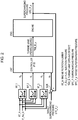
- FIG. 9 is a view illustrating an example hardware configuration of the engine intake system control device according to this embodiment.
- the engine intake system control device is an electronic control unit (ECU), for example.
- the ECU includes a processor 30, a main memory 32 that is accessed by the processor, a storage device 34 such as a flash memory, an input/output unit 40 that performs processing for inputting and outputting physical quantities, and an interface unit 22 that is an interface with an in-vehicle network.
- a PID control program 36 and map functions 38 in a table format, for example, are recorded in the storage device 34.
- the processor 30 receives the fresh air flow NAF_Q, the compressor outlet temperature CMP_Tout, and the fuel injection pressure F_INJ_P of the intake system of the engine, generates PID gains that are outputs of the map functions corresponding to the three input values by referring to the map functions 38, and performs the PID control of the controller CNT described above by executing the PID control program 36.
- FIG. 10 is a view illustrating comparison results of the reproducibility of the PID gains output by the map functions of the engine intake system control devices illustrated respectively in FIGS. 2 and 6 .
- the reproducibility values of the PID gains of the map functions are values indicating the similarity between the PID gains computed by the respective map functions of the engine intake system control devices of FIGS. 2 and 6 and the ideal PID gains, or in other words the degree to which the ideal PID gains can be reproduced.
- Each reproducibility is an average value of a ratio of the PID gains computed by the map functions in response to the inputs to the ideal PID gains.
- FIG. 10 illustrates the sum of two reproducibility values, namely the reproducibility RP1 of the proportional gain and the reproducibility RP2 of the integral gain, for each of the engine intake system control devices of FIGS. 2 and 6 .
- the ideal PID gains relative to a certain combination of the engine rotation number and the fuel injection quantity differ for each the variation pattern of the manipulated variable, and therefore the PID gains relative to a certain combination of the engine rotation number and the fuel injection quantity may be set at an average value of a plurality of ideal PID gains.
- the reproducibility values RP1, RP2 of the proportional gain and the integral gain computed by the map functions of FIG. 2 are 0.50 and 0.66, respectively, and the sum thereof is 1.16.
- the reproducibility values of the proportional gain and the integral gain computed by the map functions in relation to a certain combination of the fresh air flow, the compressor outlet temperature, and the fuel injection pressure are 0.67 and 0.79, respectively, and the sum thereof is 1.46.
- the PID gains output by the map functions of FIG. 6 are closer to the ideal PID gains than those of FIG. 2 .
- the present inventors searched the superior reproducibility of FIG. 6 on different permutations and combinations of three physical quantities among a plurality of physical quantities of the engine. As a result, as illustrated in FIG. 6 , it was found that the map functions achieved the highest reproducibility when a combination of the fresh air flow, the compressor outlet temperature, and the fuel injection pressure was used as the input.
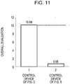
- FIG. 11 is a view illustrating a comparison result of the deviation, which is evaluation value, between the controlled variable controlled by each of the engine intake system control devices of FIGS. 2 and 6 and the target value.
- the evaluation value is a value acquired by adding, as a weighting, a time average value, over a predetermined time, of the variation width of the turbine vane opening degree that is the manipulated variable to a time average value, over a predetermined time, of the deviation e rr between the measured value SPC_P_y and the target value SPC_P_r of the supercharging pressure in a plurality of modification patterns of the target value of the controlled variable.
- the overall evaluation value of the control device illustrated in FIG. 6 is extremely small.
- the evaluation value may also be an average value of an integrated value of the deviation between the measured value SPC_P_y and the target value SPC_P_r of the supercharging pressure of the engine intake system control device over a plurality of modification patterns of the target value.
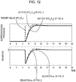
- FIG. 12 is a view illustrating examples of variation in the measured value of the controlled variable when the target value of the controlled variable is modified as described with reference to FIG. 11 .
- variation in the target value SPC_P_r of the supercharging pressure is indicated by a dotted line
- variation in the output SPC_P_y of the supercharging pressure in the control device of FIG. 2 is indicated by a dot-dash line
- variation in the output SPC_P_y of the supercharging pressure in the control device of FIG. 6 is indicated by a solid line.
- variation in the deviation e rr acquired by subtracting the target value SPC_P_r from the output SPC_P_y of the supercharging pressure in the control device of FIG. 2 is indicated by a dot-dash line, and the same deviation e rr in the control device of FIG. 6 is indicated by a solid line.
- an internal model controller (an IMC) is used instead of the PID controller of the first embodiment.
- the control gains are PID gains (the proportional gain K p , the integral gain K i , and the differential gain K d ), whereas with the internal model controller of the second embodiment, the PID gains are a proportional gain K p:IMC , an integral gain K i:IMC , and an differential gain K d:IMC .
- the gain G IMC(s) of the internal model controller, the proportional gain K p:IMC , the integral gain K i:IMC , and the differential gain K d:IMC are as indicated in the following expression.
- G IMC s K p : IMC + K i : IMC s + K d : IMC s
- T i is the integration time
- T d is the differentiation time
- ⁇ is the time lag (the time from the point at which the target value of the controlled variable is modified to the point at which the controlled variable actually starts to vary).
- the turbine vane opening degree was employed as the manipulated variable.
- this embodiment can be applied similarly by employing the valve opening degree of the bypass valve BYP_V provided between the exhaust manifold EMF connected to the supercharger SPC and the exhaust passage 2 or the opening degree of an EGR valve, which is a valve provided in an EGR device for recirculating exhaust gas from the exhaust manifold EMF side of the engine cylinders to the intake manifold IMF on the intake side, instead of the turbine vane opening degree.
- the supercharging pressure of the supercharger can be modified likewise by modifying the valve opening degree of the bypass valve BYP_V or the opening degree of the EGR valve.
- engine rotation number and the fuel injection quantity can be used as the input of the map functions in addition to the fresh air flow, the compressor outlet temperature, and the fuel injection pressure.
- the engine is an internal combustion engine having a supercharger, therefore this embodiment can be applied to either a gasoline engine or a diesel engine.
- map functions compute PID gains from the fresh air flow of the engine, the compressor outlet temperature of the supercharger, and the fuel injection pressure of the engine, and a controller computes a manipulated variable on the basis of the PID gains and a deviation between a target value and a measured value of a controlled variable.
- the PID gains computed by the map functions can be brought closer to ideal PID gains, and as a result, highly precise control can be implemented on the supercharging pressure, i.e. the pressure of the air output by the supercharger, with little overshooting or undershooting relative to the target value of the supercharging pressure.
- PID gains can be generated for different statuses.
Abstract
Description
- The present invention relates to an engine intake system control device and a control method thereof.
- An engine is used in a gasoline engine or a diesel engine of an automobile. In the field of engine control, an engine system that is a control subject exhibits strong nonlinearity, meaning that normal linear control such as proportional-integral-differential control (PID control) is not able to provide an appropriate control.
- Therefore, gain scheduling control, in which the optimum control corresponding to the status of the control subject is performed, is often employed. Gain scheduling control is also known as variable-parameter PID control since the PID gains that are the parameters of the PID control are modified according to the status of the control subject. In the gain scheduling control, since the control parameters are modified in accordance with the status of the control subject, it is important to select factors to be used to determine the status of the control subject. The values of the control parameters normally generate a map function in response to input factors.
- In engine control, factors such as the engine rotation number and the fuel injection quantity, i.e. engine operating conditions, are used as factors for determining the status of the control subject. This is illustrated in
FIG. 12 of Z. Yang, E. Winward, D. Zhao, R. Stobart: Three-Input-Three-Output Air Path Control System of a Heavy-Duty Diesel Engine, Proc. of 8th IFAC International Symposium on Advances in Automotive Control. pp. 616-622. (2016)., for example. - The followings are prior arts of the engine intake system control device.
- Patent Literature 1: Japanese Laid-open Patent Publication No.
2011-32913 - Patent Literature 2: Japanese Laid-open Patent Publication No.
2010-249057 - Patent Literature 3: Japanese Laid-open Patent Publication No.
2008-144655 - Patent Literature 4: Japanese Laid-open Patent Publication No.
2006-105098 - Non Patent Literature 1: Z. Yang, E. Winward, D. Zhao, R. Stobart: Three-Input-Three-Output Air Path Control System of a Heavy-Duty Diesel Engine, Proc. of 8th IFAC International Symposium on Advances in Automotive Control. pp. 616-622. (2016).
- However, with gain scheduling control in which PID control parameters (PID gains, control gains) are generated by map functions using the engine rotation number, the fuel injection quantity, and so on as factors, it is impossible to generate optimum PID gains corresponding to a plurality of statuses.
- In the case of an engine intake system control device, when the engine intake system shifts to a different status with the engine rotation number and the fuel injection quantity set at fixed values, PID gains are required for each of the plurality of statuses. However, map functions that use the engine rotation number and the fuel injection quantity as factors are not able to generate PID gains for a plurality of statuses in this manner.
- Therefore, an object of a first aspect of this embodiment is to provide an engine intake system control device and a control method thereof, with which PID gains are generated for different statuses.
- According to the aspect of the embodiment, an engine intake system control device configured to control an intake system of an engine, has a map function that inputs at least a fuel injection pressure of the engine, a fresh air flow, and a compressor outlet temperature of a supercharger, and outputs a control gain; and a control unit that inputs the control gain and a deviation between a controlled variable of the intake system of the engine and a target value of the intake system, and controls a manipulated variable of the intake system of the engine.
-
-
FIG. 1 is a view illustrating an example configuration of an engine that is a control subject of a control device according to this embodiment. -
FIG. 2 is a view illustrating an example configuration of an engine intake system control device having map functions for computing PID gains on the basis of an engine rotation number RT_N and a fuel injection quantity F_INJ_Q. -
FIG. 3 is a view depicting a flowchart of procedures for designing map functions. -
FIG. 4 is a view illustrating examples of ideal PID gains for six variation patterns of the manipulated variable with respect to each of two combinations of the engine rotation number and the fuel injection quantity, determined by the present inventors through experiment. -
FIG. 5 is a view illustrating the map function Mf_p when designed on the basis of the experiment illustrated inFIG. 4 . -
FIG. 6 is a view illustrating an engine intake system control device according to this embodiment, which includes map functions for computing PID gains on the basis of the fresh air flow NAF_Q input into the supercharger, the compressor outlet temperature SPC_Tout of the supercharger, and the fuel injection pressure F_INJ_P of the engine. -
FIG. 7 is a block diagram illustrating the PID controller that is the controller CNT. -
FIG. 8 is another block diagram illustrating the PID controller that is the controller CNT. -
FIG. 9 is a view illustrating an example hardware configuration of the engine intake system control device according to this embodiment. -
FIG. 10 is a view illustrating comparison results of the reproducibility of the PID gains output by the map functions of the engine intake system control devices illustrated respectively inFIGS. 2 and6 . -
FIG. 11 is a view illustrating a comparison result of evaluation values of the deviation between the controlled variable controlled by each of the engine intake system control devices ofFIGS. 2 and6 and the target value. -
FIG. 12 is a view illustrating examples of variation in the measured value of the controlled variable when the target value of the controlled variable is modified as described with reference toFIG. 11 . -
FIG. 1 is a view illustrating an example configuration of an engine that is a control subject of a control device according to this embodiment. The engine illustrated inFIG. 1 is a gasoline engine or a diesel engine used in an automobile, for example. The engine includes four cylinders CYL for an internal combustion engine, injectors INJCT attached to the cylinders, an intake manifold IMF for supplying air to the cylinders, and an exhaust manifold EMF for outputting exhaust gas from the cylinders. The injectors INJCT of the cylinders inject fuel into the cylinders, and may be provided with a sensor for measuring a fuel injection pressure INJ_P. - The engine further includes an
intake port 11 that suctions air from the outside, a supercharger SPC that compresses a flow of fresh air taken in thereby using the exhaust gas from the exhaust manifold EMF, anair supply passage 1 for supplying the air compressed by the supercharger to the intake manifold IMF, anintercooler 3 provided in theair supply passage 1, and athrottle valve 7 for controlling the quantity of air supplied to the IMF. The engine also includes an exhaust gas recirculation (EGR) device provided between the EMF and the IMF, and the EGR device is provided with anEGR cooler 4 for reducing the temperature of the exhaust gas and anEGR valve 6 for adjusting the quantity of recirculated exhaust gas. - The supercharger SPC is provided in an
intake system 10 of the engine. The supercharger SPC includes aturbine 13 that is rotated by the exhaust gas, acompressor 12 that is rotated by the rotation of the turbine so as to compress the fresh air flow, and a turbine bypass valve BYP_V provided between the exhaust manifold EMF and anexhaust passage 2. Further, a turbine vane TRB_B having an adjustable opening degree is provided in theturbine 13. A turbine in which the turbine vane opening degree is controlled variably is known as a variable nozzle turbine. A sensor for measuring a fresh air flow NAF_Q, a sensor for measuring a supercharging pressure SPC_P, and a sensor for measuring an outlet temperature SPC_Tout of thecompressor 12 of the supercharger SPC are provided in theintake system 10. - An excess
air ratio detector 9 is provided in theexhaust passage 2, and an exhaustgas aftertreatment device 5 is provided between theexhaust passage 2 and anexhaust port 8. - The opening degree of the turbine vane (the turbine vane opening degree) TRB_B and the opening degree of the bypass valve (the bypass valve opening degree) BYP_V are used as actuators of the supercharger SPC of the
intake system 10. Further, the opening degree of theEGR valve 6 controls the quantity of exhaust gas used to rotate the turbine and therefore also serves as an actuator. -
FIG. 2 is a view illustrating an example configuration of an engine intake system control device having map functions for computing PID gains on the basis of an engine rotation number RT_N and a fuel injection quantity F_INJ_Q. The engine intake system control device ofFIG. 2 includes map functions MF_1, MF_2, MF_3 that respectively inputs the engine rotation number RT_N, the fuel injection quantity F_INJ_Q, and another factor, and output PID gains Kp, Ki, Kd. - The engine intake system control device further includes a supercharger controller CNT that inputs a deviation err between a supercharging pressure SPC_R_y, which is the controlled variable of the intake system of the engine, and a target value SPC_P_r thereof and the PID gains Kp, Ki, Kd, which are control gains output by the map functions, and controls the turbine vane opening degree TRB_B_u. The supercharger controller CNT is a PID controller, for example, that computes the turbine vane opening degree TRB_B_u, which is a manipulated variable, with respect to the deviation err on the basis of the PID gains Kp, Ki, Kd. The turbine vane opening degree TRB_B_u is one of the manipulated variables of the intake system of the engine.
- The engine intake system control device includes the map functions MF_1, MF_2, MF_3 and the supercharger controller CNT, as described above, and a subtractor SUB for determining a difference between the supercharging pressure SPC_P_y and the target value SPC_P_r thereof. The engine intake system control device controls the turbine vane opening degree, which is one of the manipulated variables of the supercharger of the engine ENG, in response to variation in the target value of the supercharging pressure SPC_P_r. The map functions MF_1, MF_2, MF_3 compute the PID gains Kp, Ki, Kd of the PID controller CNT in response to input of the engine rotation number RT_N, the fuel injection quantity F_INJ_Q, and the other factor, i.e. parameters indicating the status of the engine. The controller CNT of the engine intake system control device then variably controls the turbine vane opening degree TRB_B_u that is a manipulated variable on the basis of the PID gains and the deviation err between the target value of the controlled variable and a measured value of the controlled variable of the engine.
- When, as illustrated in
FIG. 2 , the map functions MF_1, MF_2, MF_3 respectively inputs the engine rotation number RT_N, the fuel injection quantity F_INJ_Q, and another factor, and output the PID gains Kp, Ki, Kd, the PID gains output by the map functions may not match ideal PID gains corresponding to different control statuses. The reason for this is as follows. -
FIG. 3 is a view depicting a flowchart of procedures for designing map functions. The three map functions MF_1, MF_2, MF_3 are tables on which the PID gains Kp, Ki, Kd are respectively given in relation to a plurality of combinations of the engine rotation number RT_N, the fuel injection quantity F_INJ_Q, and the other factor. Accordingly, the process for designing the map functions includes processing steps S11 to S17 executed in relation to a plurality of combinations (S10, S18) of the engine rotation number RT_N, the fuel injection quantity F_INJ_Q, and the other factor that are the inputs of the map functions. - First, an actual engine is operated and the engine rotation number RT_N, the fuel injection quantity F_INJ_Q, and the other factor are fixed at one of a plurality of combinations (S11). In this state, variation occurring in the controlled variable (the supercharging pressure SPC_P_y) in response to variation in the manipulated variable (the turbine vane opening degree TRB_B_u) is recorded, and a transfer function of the intake system of the engine, which is the controlled device, is computed. A variation pattern of the manipulated variable is a variation pattern in which the turbine vane opening degree is varied from a certain value to a different value. More specifically, when designing the map functions, processing steps S13 to S15 are executed on a plurality of variation patterns (S12, S16) of the manipulated variable.
- In other words, variation occurring in the controlled variable that is the output of the controlled device (the intake system of the engine) when the manipulated variable that is the input is varied according to a predetermined variation pattern is recorded (S13). At this time, related physical quantity data may also be gathered.
- Next, the transfer function of the intake system of the engine, i.e. the model, is computed based on the variation pattern of the manipulated variable (the turbine vane opening degree TRB_B_u) and variation in the controlled variable (the supercharging pressure SPC_P_y) (S14). The transfer function includes a time constant T, a gain K, a time lag L, and so on. On the basis of the computed transfer function of the model, the ideal PID gains Kp, Ki, Kd with which to vary the supercharging pressure SPC_P_y that is the controlled variable appropriately to the target value of the supercharging pressure SPC_P_r are computed (S15). The ideal PID gains are control parameter values for varying the manipulated variable so that the controlled variable approaches the target value of the controlled variable without overshooting and without excessive delay during evaluation in a control simulation executed on paper, for example, by employing the transfer function as a virtual control subject and connecting the transfer function to a PID control-based controller. The processing steps S13 to S15 described above are performed for all variation patterns of the manipulated variable.
- Next, map functions Mf_p, Mf_i, Mf_k for respectively outputting the ideal PID gains computed from the engine rotation number RT_N and the fuel injection quantity F_INJ_Q are created (S17). The processing steps S11 to S17 described above are executed for all combinations of the engine rotation number and the fuel injection quantity (S18).
- The engine rotation number and the fuel injection quantity are commonly considered to be physical quantities from which to ascertain the status of the engine. Hence, the engine rotation number and the fuel injection quantity are used as the inputs (factors) of the map functions for outputting the optimum PID gains in accordance with the status of the engine illustrated in
FIG. 2 . - However, when the engine rotation number and the fuel injection quantity are set as the inputs (factors) of the map functions, as illustrated in
FIG. 2 , the map functions cannot output ideal PID gains corresponding to the status of the intake system of the engine. The reason for this is that when the engine rotation number and the fuel injection quantity are fixed at predetermined values during the map function design process described above, different ideal PID gains are computed for each of the plurality of variation patterns of the manipulated variable (the turbine vane opening degree). As a result, the map functions cannot output a plurality of ideal PID gains corresponding to a plurality of variation patterns of the manipulated variable in relation to an engine rotation number and a fuel injection quantity set at certain predetermined values. In conventional map function design, the map functions are designed so as to output average values or the like of a plurality of ideal PID gains in response to the input of predetermined values of the engine rotation number and the fuel injection quantity. Therefore, the designed map functions cannot output ideal PID gains for each of a plurality of statuses of the engine intake system that is the control subject. -
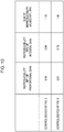
FIG. 4 is a view illustrating examples of ideal PID gains for six variation patterns of the manipulated variable with respect to each of two combinations of the engine rotation number and the fuel injection quantity, determined by the present inventors through experiment. - In the case of a first combination in which the engine rotation number RT_N and the fuel injection quantity F_INJ_Q are 1500 rpm and 40 mm3/st, respectively, different ideal PID gains Kp, Ki, Kd are computed for each of the six variation patterns, i.e. pattern Nos. 1 to 6, of the manipulated variable (the turbine vane opening degree TRB_B_u). In other words, in pattern Nos. 1 to 6, six sets of ideal PID gains Kp1, Ki1, Kd1 to Kp6, Ki6, Kd6 exist in relation to the first combination of the engine rotation number and the fuel injection quantity.
- Likewise in the case of a second combination in which the engine rotation number RT_N and the fuel injection quantity F_INJ_Q are 2500 rpm and 50 cc, respectively, different ideal PID gains Kp, Ki, Kd are computed for each of the six variation patterns, i.e. pattern Nos. 7 to 12, of the manipulated variable (the turbine vane opening degree TRB_B_u). In other words, in pattern Nos. 7 to 12, six sets of ideal PID gains Kp7, Ki7, Kd7 to Kp12, Ki12, Kd12 exist.
-
FIG. 5 is a view illustrating the map function Mf_p when designed on the basis of the experiment illustrated inFIG. 4 . The position of the ideal PID gain Kp relative to each combination of the inputs (the engine rotation number RT_N and the fuel injection quantity F_INJ_Q) of the map function Mf_p is plotted onFIG. 5 using points. As illustrated inFIG. 5 , a plurality of ideal PID gains Kp exist in a dispersed fashion relative to several combinations of the engine rotation number RT_N and the fuel injection quantity F_INJ_Q. In other words, the ideal PID gain Kp is widely dispersed at condition points of the engine rotation number and the fuel injection quantity. In the figure, vertical arrows indicate this dispersion. As a result, the map function cannot output an ideal PID gain corresponding to the status. -
FIG. 6 is a view illustrating an engine intake system control device according to this embodiment, which includes map functions for computing PID gains on the basis of the fresh air flow NAF_Q input into the supercharger, the compressor outlet temperature SPC_Tout of the supercharger, and the fuel injection pressure F_INJ_P of the engine. - The engine intake system control device of
FIG. 6 includes map functions MF_1, MF_2, MF_3 that respectively inputs the fresh air flow NAF_Q, the compressor outlet temperature SPC_Tout of the supercharger, and the fuel injection pressure F_INJ_P of the engine and output PID gains Kp, Ki, Kd. The engine intake system control device further includes the supercharger controller CNT for computing the turbine vane opening degree TRB_B_u, which is one of the manipulated variables of the intake system of the engine ENG, using, as input, the deviation err between the supercharging pressure SPC_R_y, which is the controlled variable of the intake system of the engine, and the target value SPC_P_r of the supercharging pressure and the PID gains Kp, Ki, Kd, which are the control gains output by the map functions. - For example, the supercharger controller CNT is a PID controller that computes the turbine vane opening degree TRB_B_u that is the manipulated variable with respect to the deviation err on the basis of the PID gains Kp, Ki, Kd output by the map functions.
- As illustrated in
FIG. 4 , with respect to a plurality of (six, for example) variation patterns of the manipulated variable (the turbine vane opening degree TRB_B_u), the fresh air flow NAF_Q of the supercharger, the compressor outlet temperature SPC_Tout, and the fuel injection pressure F_INJ_P of the engine take six sets of different values, namely M_af1, T_comp1, R_P1 to M_af6, T_comp6, R_P6 and M_af7, T_comp7, R_P7 to M_af12, T_comp12, R_P12. - Hence, the present inventors randomly modified combinations of a plurality of physical quantities of the engine, designed map functions that inputs the respective combinations and output ideal PID gains for the respective variation patterns of the manipulated variable, and evaluated the respective map functions.
- As a result, as illustrated in
FIG. 6 , it was found that when a combination of the fresh air flow NAF_Q of the supercharger, the compressor outlet temperature SPC_Tout, and the fuel injection pressure F_INJ_P of the engine was used as the input of the map functions, the corresponding map functions received the highest evaluation. The evaluation results will be described below. - In this embodiment, the manipulated variable of the supercharger of the engine that is the controlled device is the vane opening degree (the turbine vane opening degree) of a variable nozzle turbine, and the controlled variable is the output air pressure of the compressor, i.e. the supercharging pressure. Further, a combination of the fresh air flow NAF_Q of the supercharger, the compressor outlet temperature SPC_Tout, and the fuel injection pressure F_INJ_P of the engine is employed as the combination of physical quantities that are the input of the map functions. By employing this combination as the factor (the input) of the map functions, the map functions Mf_p, Mf_i, Mf_d can output ideal PID gains that are suitable for the status of the supercharger and correspond to a plurality of variation patterns of the manipulated variable.
- The engine intake system control device illustrated in
FIG. 6 includes a first map function Mf_1 that computes a proportional gain Kp as a first control gain from information about the fuel injection pressure, the fresh air flow, and the compressor output temperature, a second map function Mf_2 that computes an integral gain Ki as a second control gain from the information about the fuel injection pressure, the fresh air flow, and the compressor output temperature, and a third map function Mf_3 that computes a differential gain Kd as a third control gain from the information about the fuel injection pressure, the fresh air flow, and the compressor output temperature. Each map function is either a three-dimensionally structured map or a map constituted by a combination of a two-dimensional structure and a one-dimensional structure. - Further, the engine intake system control device includes the subtractor SUB for computing the deviation err between the target value SPC_P_r of the supercharging pressure and the measured value SPC_P_y of the supercharging pressure both of which are the controlled variable, and the supercharger controller CNT for computing the manipulation quantity of the turbine vane opening degree TRB_B_u from information about the proportional gain Kp, the integral gain Ki, the differential gain Kd, and the deviation err. The engine intake system control device controls the supercharging pressure SPC_P_y so as to approach the target value by variably controlling the turbine vane opening degree of the supercharger of the engine ENG that is the controlled device.
- The fuel injection pressure F_INJ_P of the engine is a physical quantity relating to the exhaust gas pressure of the engine. The fuel injection pressure F_INJ_P may be any of an injection pressure target value, a measurement value acquired by an injection pressure sensor, and an estimated value generated by a prediction model or a software sensor, of a fuel injection system.
- The fresh air flow NAF_Q is the flow rate of fresh air newly taken into the engine from the outside air and the amount of air input into the supercharger. The fresh air flow NAF_Q may be either a measurement value acquired by a fresh air flow sensor for measuring the fresh air flow or an estimated value generated by a prediction model or a software sensor.
- Further, the compressor output temperature SPC_Tout is the temperature of the compressed air output by the compressor of the supercharger, and may be either a measurement value acquired by a compressor outlet temperature sensor for measuring the temperature on the outlet side of the compressor or an estimated value generated by a prediction model or a software sensor. Furthermore, since the post-compression temperature of the compressor varies according to the atmospheric temperature, the compressor outlet temperature may also be a temperature difference between the compressor outlet temperature and the atmospheric temperature.
- The supercharger controller CNT computes the manipulation quantity of the turbine vane opening degree from the information about the proportional gain Kp, the integral gain Ki, the differential gain Kd, and the deviation err on the basis of the PID controller CNT. A gain GPID(s) of a PID controller is as indicated in the following expression.
[Math. 1]


- In the above expression, uFB(s) is a manipulated variable of feedback control and uFF(s) is a manipulated variable of feedforward control. The manipulated variable uFF(s) of the feedforward control can be determined on the basis of a map function using the engine rotation number and the injection quantity, for example, and can also be determined on the basis of a map function using information about the fuel injection pressure, the fresh air flow, and the compressor outlet temperature.
- In the embodiment of
FIG. 6 , an example using a PID controller is illustrated, but a PI controller, a PID controller, a P-D controller, a PI-D controller, an I-PD controller, and so on may be used. -
FIG. 7 is a block diagram illustrating the PID controller that is the controller CNT. The controller CNT includesmultipliers integrator 24 that determines a time integral, adifferentiator 25 that determines a time differential, and anadder 26 that adds together three control values. The controller CNT varies the manipulated variable uFB in proportion to a value acquired by multiplying the deviation err between the target value SPC_P_r and the measured value SPC_P_y of the supercharging pressure by the proportional gain Kp, varies the manipulated variable uFB in proportion to a value acquired by multiplying the deviation err by the integral gain Ki, and varies the manipulated variable uFB in proportion to a value acquired by multiplying the deviation err by the differential gain Kd. -
FIG. 8 is another block diagram illustrating the PID controller that is the controller CNT. The controller CNT ofFIG. 8 includes a feedback control unit FB, a feedforward control unit FF, and anadder 28. The feedback control unit FB is identical toFIG. 7 . The feedforward control unit FF is a map function that inputs, for example, the fuel injection pressure F_INJ_P of the engine, the fresh air flow NAF_Q of the supercharger, and the compressor output temperature SPC_Tout, and outputs a feedforward value uFF. - The feedforward control unit FF may also be a map function that inputs the engine rotation number RT_N and the fuel injection quantity F_INJ_Q of the engine and outputs the feedforward value uFF.
-
FIG. 9 is a view illustrating an example hardware configuration of the engine intake system control device according to this embodiment. The engine intake system control device is an electronic control unit (ECU), for example. The ECU includes aprocessor 30, amain memory 32 that is accessed by the processor, astorage device 34 such as a flash memory, an input/output unit 40 that performs processing for inputting and outputting physical quantities, and aninterface unit 22 that is an interface with an in-vehicle network. APID control program 36 and map functions 38 in a table format, for example, are recorded in thestorage device 34. - The
processor 30 receives the fresh air flow NAF_Q, the compressor outlet temperature CMP_Tout, and the fuel injection pressure F_INJ_P of the intake system of the engine, generates PID gains that are outputs of the map functions corresponding to the three input values by referring to the map functions 38, and performs the PID control of the controller CNT described above by executing thePID control program 36. -
FIG. 10 is a view illustrating comparison results of the reproducibility of the PID gains output by the map functions of the engine intake system control devices illustrated respectively inFIGS. 2 and6 . More specifically, the reproducibility values of the PID gains of the map functions are values indicating the similarity between the PID gains computed by the respective map functions of the engine intake system control devices ofFIGS. 2 and6 and the ideal PID gains, or in other words the degree to which the ideal PID gains can be reproduced. Each reproducibility is an average value of a ratio of the PID gains computed by the map functions in response to the inputs to the ideal PID gains. -
FIG. 10 illustrates the sum of two reproducibility values, namely the reproducibility RP1 of the proportional gain and the reproducibility RP2 of the integral gain, for each of the engine intake system control devices ofFIGS. 2 and6 . - As described above, with the map functions of
FIG. 2 , the ideal PID gains relative to a certain combination of the engine rotation number and the fuel injection quantity differ for each the variation pattern of the manipulated variable, and therefore the PID gains relative to a certain combination of the engine rotation number and the fuel injection quantity may be set at an average value of a plurality of ideal PID gains. Accordingly, the reproducibility values RP1, RP2 of the proportional gain and the integral gain computed by the map functions ofFIG. 2 are 0.50 and 0.66, respectively, and the sum thereof is 1.16. - With the map functions of
FIG. 6 , meanwhile, the reproducibility values of the proportional gain and the integral gain computed by the map functions in relation to a certain combination of the fresh air flow, the compressor outlet temperature, and the fuel injection pressure are 0.67 and 0.79, respectively, and the sum thereof is 1.46. Hence, with respect to all of the proportional gain, the integral gain, and the sum of the two gains, the PID gains output by the map functions ofFIG. 6 are closer to the ideal PID gains than those ofFIG. 2 . - The present inventors searched the superior reproducibility of
FIG. 6 on different permutations and combinations of three physical quantities among a plurality of physical quantities of the engine. As a result, as illustrated inFIG. 6 , it was found that the map functions achieved the highest reproducibility when a combination of the fresh air flow, the compressor outlet temperature, and the fuel injection pressure was used as the input. -
FIG. 11 is a view illustrating a comparison result of the deviation, which is evaluation value, between the controlled variable controlled by each of the engine intake system control devices ofFIGS. 2 and6 and the target value. The evaluation value is a value acquired by adding, as a weighting, a time average value, over a predetermined time, of the variation width of the turbine vane opening degree that is the manipulated variable to a time average value, over a predetermined time, of the deviation err between the measured value SPC_P_y and the target value SPC_P_r of the supercharging pressure in a plurality of modification patterns of the target value of the controlled variable. This means that as the time average value of the deviation over the predetermined time decreases, the measured value of the controlled variable (the supercharging pressure) becomes steadily closer to the target value thereof. Further, as the time average value of the variation width of the manipulated variable over the predetermined time decreases, the valve opening degree is manipulated in a steadily more desirable manner such that chattering, in which the valve opening degree is operated unnecessarily violently, does not occur. Accordingly, this means that as an overall evaluation, which is acquired by averaging the aforesaid evaluation value over a plurality of modification patterns of the target value, decreases, a steadily more favorable control performance is achieved. - According to
FIG. 11 , compared with the overall evaluation value of the control device illustrated inFIG. 2 , the overall evaluation value of the control device illustrated inFIG. 6 is extremely small. - Note that the evaluation value may also be an average value of an integrated value of the deviation between the measured value SPC_P_y and the target value SPC_P_r of the supercharging pressure of the engine intake system control device over a plurality of modification patterns of the target value.
-
FIG. 12 is a view illustrating examples of variation in the measured value of the controlled variable when the target value of the controlled variable is modified as described with reference toFIG. 11 . InFIG. 12 , with respect to the supercharging pressure, variation in the target value SPC_P_r of the supercharging pressure is indicated by a dotted line, variation in the output SPC_P_y of the supercharging pressure in the control device ofFIG. 2 is indicated by a dot-dash line, and variation in the output SPC_P_y of the supercharging pressure in the control device ofFIG. 6 is indicated by a solid line. Further, inFIG. 12 , with respect to the deviation, variation in the deviation err acquired by subtracting the target value SPC_P_r from the output SPC_P_y of the supercharging pressure in the control device ofFIG. 2 is indicated by a dot-dash line, and the same deviation err in the control device ofFIG. 6 is indicated by a solid line. - It is evident from
FIG. 12 that the output SPC_P_y follows the target value SPC_P_r more closely, i.e. without overshooting, in the control device ofFIG. 6 than in the control device ofFIG. 2 . - In a second embodiment, an internal model controller (an IMC) is used instead of the PID controller of the first embodiment. In the first embodiment, the control gains are PID gains (the proportional gain Kp, the integral gain Ki, and the differential gain Kd), whereas with the internal model controller of the second embodiment, the PID gains are a proportional gain Kp:IMC, an integral gain Ki:IMC, and an differential gain Kd:IMC.
- More specifically, in the case of an internal model controller (an IMC), the gain GIMC(s) of the internal model controller, the proportional gain Kp:IMC, the integral gain Ki:IMC, and the differential gain Kd:IMC are as indicated in the following expression.
[Math. 2]


- Here, Ti is the integration time, Td is the differentiation time, and λ is the time lag (the time from the point at which the target value of the controlled variable is modified to the point at which the controlled variable actually starts to vary). With an internal model controller, Kp(λ), the integration time Ti, and the differentiation time Td can respectively be computed by postulating a mathematical model based on the dynamic behavior of the control subject and determining a control law in accordance with the structure of the mathematical model.
- In the above embodiments, the turbine vane opening degree was employed as the manipulated variable. However, this embodiment can be applied similarly by employing the valve opening degree of the bypass valve BYP_V provided between the exhaust manifold EMF connected to the supercharger SPC and the
exhaust passage 2 or the opening degree of an EGR valve, which is a valve provided in an EGR device for recirculating exhaust gas from the exhaust manifold EMF side of the engine cylinders to the intake manifold IMF on the intake side, instead of the turbine vane opening degree. In the engine, the supercharging pressure of the supercharger can be modified likewise by modifying the valve opening degree of the bypass valve BYP_V or the opening degree of the EGR valve. - Further, the engine rotation number and the fuel injection quantity can be used as the input of the map functions in addition to the fresh air flow, the compressor outlet temperature, and the fuel injection pressure.
- Furthermore, the engine is an internal combustion engine having a supercharger, therefore this embodiment can be applied to either a gasoline engine or a diesel engine.
- According to this embodiment, as described above, in a gain scheduling control device for an intake system of an engine, map functions compute PID gains from the fresh air flow of the engine, the compressor outlet temperature of the supercharger, and the fuel injection pressure of the engine, and a controller computes a manipulated variable on the basis of the PID gains and a deviation between a target value and a measured value of a controlled variable. Thus, the PID gains computed by the map functions can be brought closer to ideal PID gains, and as a result, highly precise control can be implemented on the supercharging pressure, i.e. the pressure of the air output by the supercharger, with little overshooting or undershooting relative to the target value of the supercharging pressure. According to the embodiment, PID gains can be generated for different statuses.
Claims (13)
- An engine intake system control device configured to control an intake system of an engine, comprising:a map function that inputs at least a fuel injection pressure of the engine, a fresh air flow, and a compressor outlet temperature of a supercharger, and outputs a control gain; anda control unit that inputs the control gain and a deviation between a controlled variable of the intake system of the engine and a target value of the intake system, and controls a manipulated variable of the intake system of the engine.
- The engine intake system control device according to claim 1, wherein the controlled variable is a supercharging pressure of the supercharger, and the manipulated variable is any of a turbine vane opening degree of the supercharger of the engine, a valve opening degree in a bypass passage of the supercharger, and a valve opening degree of an exhaust gas recirculation device.
- The engine intake system control device according to claim 1, wherein the control unit is a PID controller, and the control gain is PID gains including a proportional gain, an integral gain, and a differential gain.
- The engine intake system control device according to claim 2, wherein the control unit is a PID controller, and the control gain is PID gains including a proportional gain, an integral gain, and a differential gain.
- The engine intake system control device according to claim 1, wherein the control unit is an internal model controller.
- The engine intake system control device according to claim 2, wherein the control unit is an internal model controller.
- The engine intake system control device according to claim 1, wherein the compressor outlet temperature is a temperature difference relative to the atmospheric temperature.
- The engine intake system control device according to claim 2, wherein the compressor outlet temperature is a temperature difference relative to the atmospheric temperature.
- The engine intake system control device according to claim 1, wherein the fuel injection pressure is either a measured value of the fuel injection pressure of the engine or a target value of the fuel injection pressure.
- The engine intake system control device according to claim 2, wherein the fuel injection pressure is either a measured value of the fuel injection pressure of the engine or a target value of the fuel injection pressure.
- The engine intake system control device according to claim 1, wherein the map function also inputs an engine rotation number and a fuel injection quantity.
- The engine intake system control device according to claim 2, wherein the map function also inputs an engine rotation number and a fuel injection quantity.
- An engine intake system control method for controlling an intake system of an engine, the method including processing for:inputting at least a fuel injection pressure of the engine, a fresh air flow, and a compressor outlet temperature of a supercharger, and outputting a control gain by referring to a map function; andinputting the control gain and a deviation between a controlled variable of the intake system of the engine and a target value thereof, and controlling a manipulated variable of the intake system of the engine.
Applications Claiming Priority (1)
| Application Number | Priority Date | Filing Date | Title |
|---|---|---|---|
| JP2019132090A JP7359367B2 (en) | 2019-07-17 | 2019-07-17 | Engine intake system control device and its control method |
Publications (2)
| Publication Number | Publication Date |
|---|---|
| EP3767097A1 true EP3767097A1 (en) | 2021-01-20 |
| EP3767097A8 EP3767097A8 (en) | 2021-03-10 |
Family
ID=71620286
Family Applications (1)
| Application Number | Title | Priority Date | Filing Date |
|---|---|---|---|
| EP20185929.5A Pending EP3767097A1 (en) | 2019-07-17 | 2020-07-15 | Engine intake system control device and control method thereof |
Country Status (3)
| Country | Link |
|---|---|
| US (1) | US20210017921A1 (en) |
| EP (1) | EP3767097A1 (en) |
| JP (1) | JP7359367B2 (en) |
Citations (9)
| Publication number | Priority date | Publication date | Assignee | Title |
|---|---|---|---|---|
| US6128902A (en) * | 1999-01-26 | 2000-10-10 | Ford Global Technologies, Inc. | Control method and apparatus for turbocharged diesel engines having exhaust gas recirculation |
| JP2005320937A (en) * | 2004-05-11 | 2005-11-17 | Toyota Motor Corp | Supercharging pressure controller of internal combustion engine |
| JP2006105098A (en) | 2004-10-08 | 2006-04-20 | Nissan Motor Co Ltd | Cylinder suction air volume control device and cylinder suction air volume control method of engine |
| JP2008144655A (en) | 2006-12-08 | 2008-06-26 | Keihin Corp | Device and method for controlling internal combustion engine |
| US20090090107A1 (en) * | 2007-09-28 | 2009-04-09 | Bilal Youssef | Method for Controlling a Turbocharger Using a Physical Model of the Turbocharger Speed |
| JP4506651B2 (en) * | 2005-11-16 | 2010-07-21 | 株式会社デンソー | Fuel injection control device |
| JP2010249057A (en) | 2009-04-16 | 2010-11-04 | Isuzu Motors Ltd | Control method and control device for internal combustion engine |
| JP2011032913A (en) | 2009-07-31 | 2011-02-17 | Transtron Inc | Device and method of controlling intake system |
| EP3205864A1 (en) * | 2016-02-12 | 2017-08-16 | Bosch Corporation | Engine controller and engine control method |
Family Cites Families (12)
| Publication number | Priority date | Publication date | Assignee | Title |
|---|---|---|---|---|
| JP2788447B2 (en) * | 1987-09-03 | 1998-08-20 | マツダ株式会社 | Engine output control device |
| GB9800282D0 (en) | 1998-01-08 | 1998-03-04 | Rolls Royce Cars Limited | Turbocharger system |
| JP3859010B2 (en) | 1999-08-20 | 2006-12-20 | 日産自動車株式会社 | Turbocharger control device |
| JP4434038B2 (en) | 2004-04-05 | 2010-03-17 | 株式会社デンソー | Exhaust gas purification device for internal combustion engine |
| JP2006233811A (en) | 2005-02-23 | 2006-09-07 | Kobelco Contstruction Machinery Ltd | Hybrid type electric working machine |
| CN101305171B (en) | 2005-11-11 | 2010-05-19 | 丰田自动车株式会社 | Control device of internal combustion engine |
| JP4613920B2 (en) | 2007-03-16 | 2011-01-19 | 株式会社デンソー | Fuel injection device for internal combustion engine |
| JP5760773B2 (en) | 2011-07-11 | 2015-08-12 | トヨタ自動車株式会社 | Control device for turbocharged internal combustion engine |
| US9765621B2 (en) * | 2014-10-21 | 2017-09-19 | Toyota Motor Engineering & Manufacturing North America, Inc. | Switch gain scheduled explicit model predictive control of diesel engines |
| US10100679B2 (en) | 2015-08-28 | 2018-10-16 | General Electric Company | Control system for managing steam turbine rotor stress and method of use |
| JP2017198091A (en) | 2016-04-25 | 2017-11-02 | トヨタ自動車株式会社 | Control device of internal combustion engine |
| JP2019027290A (en) | 2017-07-26 | 2019-02-21 | 三菱自動車工業株式会社 | Engine control device |
-
2019
- 2019-07-17 JP JP2019132090A patent/JP7359367B2/en active Active
-
2020
- 2020-07-14 US US16/928,336 patent/US20210017921A1/en active Pending
- 2020-07-15 EP EP20185929.5A patent/EP3767097A1/en active Pending
Patent Citations (9)
| Publication number | Priority date | Publication date | Assignee | Title |
|---|---|---|---|---|
| US6128902A (en) * | 1999-01-26 | 2000-10-10 | Ford Global Technologies, Inc. | Control method and apparatus for turbocharged diesel engines having exhaust gas recirculation |
| JP2005320937A (en) * | 2004-05-11 | 2005-11-17 | Toyota Motor Corp | Supercharging pressure controller of internal combustion engine |
| JP2006105098A (en) | 2004-10-08 | 2006-04-20 | Nissan Motor Co Ltd | Cylinder suction air volume control device and cylinder suction air volume control method of engine |
| JP4506651B2 (en) * | 2005-11-16 | 2010-07-21 | 株式会社デンソー | Fuel injection control device |
| JP2008144655A (en) | 2006-12-08 | 2008-06-26 | Keihin Corp | Device and method for controlling internal combustion engine |
| US20090090107A1 (en) * | 2007-09-28 | 2009-04-09 | Bilal Youssef | Method for Controlling a Turbocharger Using a Physical Model of the Turbocharger Speed |
| JP2010249057A (en) | 2009-04-16 | 2010-11-04 | Isuzu Motors Ltd | Control method and control device for internal combustion engine |
| JP2011032913A (en) | 2009-07-31 | 2011-02-17 | Transtron Inc | Device and method of controlling intake system |
| EP3205864A1 (en) * | 2016-02-12 | 2017-08-16 | Bosch Corporation | Engine controller and engine control method |
Non-Patent Citations (2)
| Title |
|---|
| Z. YANGE. WINWARDD. ZHAOR. STOBART: "Three-Input-Three-Output Air Path Control System of a Heavy-Duty Diesel Engine", PROC. OF 8TH IFAC INTERNATIONAL SYMPOSIUM ON ADVANCES IN AUTOMOTIVE CONTROL, 2016, pages 616 - 622 |
| Z. YANGE. WINWARDD. ZHAOR. STOBART: "Three-Input-Three-Output Air Path Control System of a Heavy-Duty Diesel Engine", PROC. OF 8TH IFAC INTERNATIONAL SYMPOSIUM ON ADVANCES IN AUTOMOTIVE CONTROL., 2016, pages 616 - 622 |
Also Published As
| Publication number | Publication date |
|---|---|
| US20210017921A1 (en) | 2021-01-21 |
| EP3767097A8 (en) | 2021-03-10 |
| JP7359367B2 (en) | 2023-10-11 |
| JP2021017816A (en) | 2021-02-15 |
Similar Documents
| Publication | Publication Date | Title |
|---|---|---|
| US10634073B2 (en) | Variable geometry turbocharger feed forward control system and method | |
| US10830164B2 (en) | Fresh air flow and exhaust gas recirculation control system and method | |
| US6035640A (en) | Control method for turbocharged diesel engines having exhaust gas recirculation | |
| EP1862657B1 (en) | Fuel jetting control unit for internal combustion engine | |
| JP5665804B2 (en) | Exhaust gas recirculation control method in compression ignition engine system with turbocharger | |
| US7127892B2 (en) | Techniques for determining turbocharger speed | |
| EP1864012B1 (en) | Coordinated multivariable control of fuel and air in engines | |
| JP6534425B2 (en) | Control device and control method for internal combustion engine | |
| WO2011142038A1 (en) | Control device of internal combustion engine | |
| EP0185552A2 (en) | Apparatus for controlling operating state of an internal combustion engine | |
| EP2290209A2 (en) | Intake manifold oxygen control | |
| US20050228573A1 (en) | Multivariable actuator control for an internal combustion engine | |
| WO2011086708A1 (en) | Control device for internal combustion engine | |
| CN113756969A (en) | EGR control method and device and electronic equipment | |
| US6397820B1 (en) | Method and device for controlling a combustion engine | |
| EP3767097A1 (en) | Engine intake system control device and control method thereof | |
| JP3898114B2 (en) | Intake air amount estimation method, estimation device, intake air amount control method and control device for internal combustion engine | |
| Unver et al. | Modeling and validation of turbocharged diesel engine airpath and combustion systems | |
| KR102323282B1 (en) | Method for determining the cylinder air charging of a combustion engine in non-fired operation | |
| US11719181B2 (en) | Internal combustion engine controller | |
| JP6458479B2 (en) | Exhaust gas recirculation control device | |
| CN106401770B (en) | Method for processing sensor signals | |
| US11781498B2 (en) | Controls for break-in operation of green engines | |
| CN113074051B (en) | EGR valve exhaust gas flow value calculation method and system and engine parameter adjustment method | |
| CN113614349B (en) | Intake manifold pressure control strategy |
Legal Events
| Date | Code | Title | Description |
|---|---|---|---|
| PUAI | Public reference made under article 153(3) epc to a published international application that has entered the european phase |
Free format text: ORIGINAL CODE: 0009012 |
|
| STAA | Information on the status of an ep patent application or granted ep patent |
Free format text: STATUS: THE APPLICATION HAS BEEN PUBLISHED |
|
| AK | Designated contracting states |
Kind code of ref document: A1 Designated state(s): AL AT BE BG CH CY CZ DE DK EE ES FI FR GB GR HR HU IE IS IT LI LT LU LV MC MK MT NL NO PL PT RO RS SE SI SK SM TR |
|
| AX | Request for extension of the european patent |
Extension state: BA ME |
|
| RAP1 | Party data changed (applicant data changed or rights of an application transferred) |
Owner name: TRANSTRON INC. |
|
| STAA | Information on the status of an ep patent application or granted ep patent |
Free format text: STATUS: REQUEST FOR EXAMINATION WAS MADE |
|
| 17P | Request for examination filed |
Effective date: 20210525 |
|
| RBV | Designated contracting states (corrected) |
Designated state(s): AL AT BE BG CH CY CZ DE DK EE ES FI FR GB GR HR HU IE IS IT LI LT LU LV MC MK MT NL NO PL PT RO RS SE SI SK SM TR |
|
| STAA | Information on the status of an ep patent application or granted ep patent |
Free format text: STATUS: EXAMINATION IS IN PROGRESS |
|
| 17Q | First examination report despatched |
Effective date: 20230424 |