EP3767042A1 - Construction machine - Google Patents
Construction machine Download PDFInfo
- Publication number
- EP3767042A1 EP3767042A1 EP18910095.1A EP18910095A EP3767042A1 EP 3767042 A1 EP3767042 A1 EP 3767042A1 EP 18910095 A EP18910095 A EP 18910095A EP 3767042 A1 EP3767042 A1 EP 3767042A1
- Authority
- EP
- European Patent Office
- Prior art keywords
- point
- work
- monitor
- information
- monitor point
- Prior art date
- Legal status (The legal status is an assumption and is not a legal conclusion. Google has not performed a legal analysis and makes no representation as to the accuracy of the status listed.)
- Granted
Links
Images







Classifications
-
- E—FIXED CONSTRUCTIONS
- E02—HYDRAULIC ENGINEERING; FOUNDATIONS; SOIL SHIFTING
- E02F—DREDGING; SOIL-SHIFTING
- E02F9/00—Component parts of dredgers or soil-shifting machines, not restricted to one of the kinds covered by groups E02F3/00 - E02F7/00
- E02F9/26—Indicating devices
-
- E—FIXED CONSTRUCTIONS
- E02—HYDRAULIC ENGINEERING; FOUNDATIONS; SOIL SHIFTING
- E02F—DREDGING; SOIL-SHIFTING
- E02F3/00—Dredgers; Soil-shifting machines
- E02F3/04—Dredgers; Soil-shifting machines mechanically-driven
- E02F3/96—Dredgers; Soil-shifting machines mechanically-driven with arrangements for alternate or simultaneous use of different digging elements
- E02F3/963—Arrangements on backhoes for alternate use of different tools
-
- E—FIXED CONSTRUCTIONS
- E02—HYDRAULIC ENGINEERING; FOUNDATIONS; SOIL SHIFTING
- E02F—DREDGING; SOIL-SHIFTING
- E02F3/00—Dredgers; Soil-shifting machines
- E02F3/04—Dredgers; Soil-shifting machines mechanically-driven
- E02F3/28—Dredgers; Soil-shifting machines mechanically-driven with digging tools mounted on a dipper- or bucket-arm, i.e. there is either one arm or a pair of arms, e.g. dippers, buckets
- E02F3/36—Component parts
- E02F3/40—Dippers; Buckets ; Grab devices, e.g. manufacturing processes for buckets, form, geometry or material of buckets
-
- E—FIXED CONSTRUCTIONS
- E02—HYDRAULIC ENGINEERING; FOUNDATIONS; SOIL SHIFTING
- E02F—DREDGING; SOIL-SHIFTING
- E02F3/00—Dredgers; Soil-shifting machines
- E02F3/04—Dredgers; Soil-shifting machines mechanically-driven
- E02F3/96—Dredgers; Soil-shifting machines mechanically-driven with arrangements for alternate or simultaneous use of different digging elements
- E02F3/965—Dredgers; Soil-shifting machines mechanically-driven with arrangements for alternate or simultaneous use of different digging elements of metal-cutting or concrete-crushing implements
-
- E—FIXED CONSTRUCTIONS
- E02—HYDRAULIC ENGINEERING; FOUNDATIONS; SOIL SHIFTING
- E02F—DREDGING; SOIL-SHIFTING
- E02F3/00—Dredgers; Soil-shifting machines
- E02F3/04—Dredgers; Soil-shifting machines mechanically-driven
- E02F3/96—Dredgers; Soil-shifting machines mechanically-driven with arrangements for alternate or simultaneous use of different digging elements
- E02F3/966—Dredgers; Soil-shifting machines mechanically-driven with arrangements for alternate or simultaneous use of different digging elements of hammer-type tools
-
- E—FIXED CONSTRUCTIONS
- E02—HYDRAULIC ENGINEERING; FOUNDATIONS; SOIL SHIFTING
- E02F—DREDGING; SOIL-SHIFTING
- E02F9/00—Component parts of dredgers or soil-shifting machines, not restricted to one of the kinds covered by groups E02F3/00 - E02F7/00
- E02F9/26—Indicating devices
- E02F9/264—Sensors and their calibration for indicating the position of the work tool
Definitions
- the present invention relates to a construction machine such as a hydraulic excavator.
- Patent Document 1 discloses a display system for a work machine having a work implement to which a bucket is attached, the display system including: a generating section that uses information on the shape and dimensions of the bucket to generate drawing information for drawing an image of the bucket in a side view; and a display section that displays the image of the bucket in the side view on the basis of the drawing information generated by the generating section, and an image illustrating a cross-section of a terrain.
- the information on the shape and dimensions of the bucket includes: in a side view of the bucket, a distance between a blade tip of the bucket and a bucket pin used to attach the bucket to the work implement; an angle formed between a straight line linking the blade tip and the bucket pin and a straight line indicating the bottom surface of the bucket; a position of the blade tip; a position of the bucket pin; and at least one position of an external surface of the bucket, the one position being located between a portion that couples the bucket to the work implement and the blade tip (the paragraph [0006]).
- Patent Document 1 Japanese Patent No. 6080983
- a sense of discomfort felt by an operator can be reduced by making the shape of the bucket displayed on the display section correspond to the shape of a newly attached bucket in a case where the type of the bucket attached to the work implement is changed from one to another.
- the work devices of a construction machine include, other than a bucket used in excavation work, a hydraulic breaker used in fracturing work, a ripper and the like (a work device having a acute tip shape), a secondary breaker used in dismantling work, and a grapple and the like (a work device that has a movable section, and perform crushing and gripping).
- a work-machine display system described in Patent Document 1 is not suited for a construction machine used also for work other than excavation work since the work-machine display system does not support work devices other than the bucket.
- the present invention has been made in view of the problem explained above, and an object thereof is to provide a construction machine that can display various work devices including a bucket on a display device without causing a sense of discomfort.
- the present invention provides a construction machine including: a work implement having a work device attached thereto pivotably via a first coupling pin and a second coupling pin; a display controller that creates a drawing figure representing a side surface of the work device on a basis of drawing information and dimensional information on the work device, and creates a target-surface figure representing a target surface on a basis of target-surface information; and a display device that displays the drawing figure and the target-surface figure.
- the dimensional information on the work device includes positional information on a first coupling point positioned on a central axis of the first coupling pin, a second coupling point positioned on a central axis of the second coupling pin, and a first monitor point positioned on a contour of the work device, the contour being projected onto the operation plane
- the drawing information on the work device includes image information on a first drawing figure representing at least part of the work device, the part including the first coupling point, the second coupling point and the first monitor point.
- the display controller calculates a posture of the work implement; calculates a coordinate value of each of the first coupling point, the second coupling point and the first monitor point in a coordinate system on an image on the display device on a basis of the postural information on the work implement and the dimensional information on the work device; deforms the first drawing figure to create a first post-deformation drawing figure such that a triangle having vertexes at the first coupling point, the second coupling point and the first monitor point in the first drawing figure becomes congruent with a triangle having vertexes at the first coupling point, the second coupling point and the first monitor point in the coordinate system on the image on the display device; and arranges the first post-deformation drawing figure on a screen of the display device such that positions of the first coupling point, the second coupling point and the first monitor point in the first post-deformation drawing figure are arranged correspondingly to positions of the first coupling point, the second coupling point and the first monitor point, respectively, in the coordinate system on the image on the display device.
- the first post-deformation drawing figure is created such that the triangle having vertexes at the first coupling point, the second coupling point and the first monitor point in the first drawing figure representing at least part of the work device becomes congruent with the triangle having vertexes at the first coupling point, the second coupling point and the first monitor point in the coordinate system on the image on the display device, and the first post-deformation drawing figure is arranged on the screen of the display device such that the positions of the first coupling point, the second coupling point and the first monitor point in the first post-deformation drawing figure are arranged correspondingly to the positions of the first coupling point, the second coupling point and the first monitor point, respectively, in the coordinate system on the image on the display device.
- a construction machine can display various work devices including a bucket on a display device without causing a sense of discomfort.
- FIG. 1 is a side view illustrating a hydraulic excavator according to an embodiment of the present invention.
- the hydraulic excavator 1 includes a lower track structure 5, an upper swing structure 4 and a work implement 3.
- the upper swing structure 4 and the lower track structure 5 constitute a vehicle main body 2.
- the lower track structure 5 has crawlers 15a and 15b on both sides. By travel motors 16a and 16b being rotated by means of hydraulic pressures, the crawlers 15a and 15b are driven individually, and the hydraulic excavator 1 travels.
- the upper swing structure 4 is connected pivotably to the lower track structure 5 via a slewing ring 17, and is driven by being rotated by a swing motor 13 by means of a hydraulic pressure.
- the upper swing structure 4 has a cab 12, the swing motor 13, an engine and a hydraulic pump which are not illustrated, and a hydraulic controller 14 (illustrated in FIG. 2 ) constituted by hydraulic control valves and the like.
- a machine-body operation device 18 and a display device 19 that are mentioned below are installed in the cab 12.
- a machine-body inclination-angle sensor 32 that senses an inclination of the machine body is attached to the upper swing structure 4.
- Antennas 23a and 23b are attached to an upper portion of the upper swing structure 4.
- the antennas 23a and 23b are used for receiving signals from an artificial satellite which is not illustrated, and sensing the current position of the hydraulic excavator 1 on the earth.
- the work implement 3 has a boom 6, an arm 7, a work device 8 (a bucket 8b in the example illustrated in FIG. 1 ), a first cylinder 9, a second cylinder 10 and a third cylinder 11.
- the boom 6 is attached pivotably to the upper swing structure 4 via a first link pin 20.
- the arm 7 is attached pivotably to a tip portion of the boom 6 via a second link pin 21.
- the work device 8 is attached pivotably to a tip portion of the arm 7 via a third link pin (first coupling pin) 22.
- the first cylinder 9 is attached pivotably to the boom 6 via a first cylinder pin 42
- the second cylinder 10 is attached pivotably to the arm 7 via a second cylinder pin 43
- the third cylinder 11 is attached pivotably to the work device 8 via a third cylinder pin (second coupling pin) 44.
- the first cylinder 9, the second cylinder 10 and the third cylinder 11 extend and retract by means of hydraulic pressures to drive the boom 6, the arm 7 and the work device 8, respectively.
- First to third rotation-angle sensors 33 to 35 that sense the postures of the boom 6, the arm 7 and the work device 8 are attached to the boom 6, the arm 7 and the work device 8, respectively.
- FIG. 2 is a block diagram illustrating the configurations of a machine-body control system 24 and a display system 25 mounted on the hydraulic excavator 1.
- the machine-body control system 24 has the first cylinder 9, the second cylinder 10, the third cylinder 11, the swing motor 13, the travel motors 16a and 16b, the hydraulic controller 14, the machine-body operation device 18 and a machine-body controller 26.
- the hydraulic controller 14 distributes and supplies a hydraulic operating fluid delivered from the hydraulic pump to a plurality of hydraulic actuators including the first cylinder 9, the second cylinder 10, the third cylinder 11, the swing motor 13 and the travel motors 16a and 16b, and drives them.
- the machine-body operation device 18 has an operation member 27 and an operation-amount sensing section 28.
- the operation member 27 is a member (e.g. a work lever) for an operator in the cab 12, for instruction of driving of the first cylinder 9, the second cylinder 10, the third cylinder 11, the swing motor 13 and the travel motors 16a and 16b.
- the operation-amount sensing section 28 senses an operation amount of the operation member 27, and sends a sensing signal to the machine-body controller 26.
- the machine-body controller 26 has an input/output section 29 such as an A/D converting section, a D/A converting section and a digital input/output device, and a calculating section 30 such as a CPU.
- the input/output section 29 of the machine-body controller 26 sends, to the calculating section 30, signals input from the machine-body operation device 18 and the hydraulic controller 14, and sends a result of calculation performed by the calculating section 30 to the hydraulic controller 14.
- the calculating section 30 of the machine-body controller 26 calculates a command value to the hydraulic controller 14 on the basis of an operation amount indicated by a signal sent from the operation-amount sensing section 28 and a state quantity of the hydraulic controller 14.
- the display system 25 has the machine-body inclination-angle sensor 32, the first to third rotation-angle sensors 33 to 35, a correction information receiving section 36, the antennas 23a and 23b, the display device 19 and a display controller 31.
- the machine-body inclination-angle sensor 32 is an inertial measurement unit (IMU), for example, and typically is a sensor formed by combining an angular velocity sensor and an acceleration sensor.
- IMU inertial measurement unit
- the machine-body inclination-angle sensor 32 is attached to the upper swing structure 4, and is used for sensing the angle formed between a front-rear direction of the upper swing structure 4 and the vertical (gravity) direction, when it is defined that the horizontal direction on the operation plane of the work implement 3 is the front-rear direction and the direction perpendicular to the operation plane of the work implement 3 is the left-right direction.
- the first to third rotation-angle sensors 33 to 35 are IMUs, for example, which are attached to the boom 6, the arm 7, and the work device 8, respectively, sense the angle around the first link pin 20 formed between the boom 6 and the vertical (gravity) direction, the angle around the second link pin 21 formed between the arm 7 and the vertical (gravity) direction, and the angle around the third link pin 22 formed between the work device 8 and the vertical (gravity) direction, and output the angle of the boom 6 relative to the upper swing structure 4, the angle of the arm 7 relative to the boom 6, and the angle of the work device 8 relative to the arm 7, respectively.
- the correction information receiving section 36 is a wireless communication section, for example, and receives correction information that is transmitted wirelessly from a correction information transmitting section not illustrated and located outside the hydraulic excavator 1, and that is for use in calculation of a global position.
- the display device 19 has an operation section 37, and a display section 38.
- the operation section 37 of the display device 19 is a switch, for example.
- the operation section 37 is operated by an operator to switch display information, and add or change settings of coordinate information on a target surface, and drawing information like the type and dimensions of the work device 8 stored in a storage section 41 of the display controller 31 mentioned below.
- the display section 38 of the display device 19 is a liquid crystal display and a speaker, for example, and displays drawing information calculated by a calculating section 40 of the display controller 31 for an operator to check work contents.
- the display device 19 may be one like a touch panel formed by integrating the operation section 37 and the display section 38, for example.
- the display controller 31 has an input/output section 39 such as an A/D converting section, a D/A converting section or a digital input/output device, the calculating section 40 such as a CPU and a storage section 41 such as a ROM or a RAM.
- the input/output section 39 such as an A/D converting section, a D/A converting section or a digital input/output device
- the calculating section 40 such as a CPU
- a storage section 41 such as a ROM or a RAM.
- the input/output section 39 of the display controller 31 sends, to the calculating section 40, angle signals input from the machine-body inclination-angle sensor 32 and the first to third rotation-angle sensors 33 to 35, sensing signals of the antennas 23a and 23b, and operation signals input from the operation section 37 of the display device 19, and sends a result of calculation performed by the calculating section 40 to the display section 38 of the display device 19.
- the input/output section 39 of the display controller 31 further has an external connection terminal (e.g. a USB (Universal Serial Bus) terminal) that can be connected with an external storage device (e.g. a USB memory) 90, and can store, in the storage section 41, target-surface information and work-device drawing information that are stored in the external storage device 90 and edited in another electronic device.
- an external connection terminal e.g. a USB (Universal Serial Bus) terminal
- an external storage device e.g. a USB memory
- target-surface information and work-device drawing information that are stored in the external storage device 90 and edited in another electronic device.
- the display controller 31 has the storage section 41 that stores drawing information and dimensional information on the work device 8, and the input/output section 39 that can be connected with the external storage device 90, and the display controller 31 can store, in the storage section 41, drawing information and dimensional information on the work device 8 stored in the external storage device 90, via the input/output section 39.
- FIG. 3 is a block diagram illustrating the configuration of the calculating section 40 of the display controller 31.
- the calculating section 40 of the display controller 31 has a global-position calculating section 40a, a posture calculating section 40b, a work-device-position calculating section 40c and a drawing calculating section 40d.
- the storage section 41 of the display controller 31 stores a machine-body dimensional parameter, an angle conversion parameter, target-surface information and work-device drawing information.
- the machine-body dimensional parameter includes, for example, dimensions of the boom 6, the arm 7 and the work device 8, and relative positions between the antennas 23a and 23b, and the first link pin 20 (three-dimensional vectors, and the like).
- the target-surface information includes coordinates of a cross-section on at least one plane which is a work target of the hydraulic excavator 1.
- the work-device drawing information includes image information on a drawing figure of the work device 8, and coordinate values on an image associated with the drawing figure.
- the global-position calculating section 40a uses an RTK-GNSS (RealTime Kinematic-Global Navigation Satellite System; GNSS stands for the Global Navigation Satellite System) to calculate the current positions of the antenna 23a and 23b in the global (earth) coordinate system.
- RTK-GNSS RealTime Kinematic-Global Navigation Satellite System
- GNSS stands for the Global Navigation Satellite System
- the posture calculating section 40b calculates a left-right inclination angle ⁇ 0x of the upper swing structure 4, a front-rear inclination angle ⁇ 0y of the upper swing structure 4, an angle ⁇ 1 around the first link pin 20 of the boom 6 relative to the machine body, an angle ⁇ 2 around the second link pin 21 of the arm 7 relative to the boom 6, and an angle ⁇ 3 around the third link pin 22 of the work device 8 relative to the arm 7.
- the work-device-position calculating section 40c defines a work-implement operation plane (X-Z plane) as a two-dimensional coordinate system.
- the work-implement operation plane (X-Z plane) has its origin at the center of the first link pin 20, passes through the origin, and the centers of the second and third link pins 21 and 22, and is formed by a Z axis and an X axis.
- the positive direction of the Z axis is the upward direction relative to the direction of gravity.
- the X axis is perpendicular to the Z axis, and the positive direction of the X axis is the direction of extension of the work implement 3.
- the work-device-position calculating section 40c calculates the coordinate, on the work-implement operation plane (X-Z plane), of a first monitor point MP1 which is located in the work device 8 and is a point of interest in terms of work, the coordinate of the central axis of the third link pin 22, and the coordinate of the central axis of the third cylinder pin 44.
- the work-device-position calculating section 40c further calculates the first monitor point MP1, the coordinates of the central axis of the third link pin 22, and the coordinates of the central axis of the third cylinder pin 44 in the global (earth) coordinate system.
- the drawing calculating section 40d creates a guidance image, and outputs the guidance image to the display section 38.
- the hydraulic excavator 1 according to a first embodiment of the present invention is explained by using FIG. 4 to FIG. 6 .
- the hydraulic excavator 1 according to the present embodiment includes a hydraulic breaker as the work device 8.
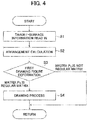
- FIG. 4 is a flowchart illustrating one example of a drawing-calculation process performed by the display controller 31 according to the present embodiment.
- the display controller 31 creates a side surface image (guidance image) illustrating a positional relationship between a target surface and the work device 8 in accordance with the flowchart illustrated in FIG. 4 .
- target-surface information is read in from the storage section 41, and a target-surface figure 48 (illustrated in FIG. 5(a) ) is created.
- the target-surface information is polygon data constituted by line segments and a plane arranged in the global coordinate system, for example.
- the target-surface figure 48 is a line of intersection between the work-implement operation plane (X-Z plane) and the plane constituting the polygon data, and is defined in a local coordinate system on the work-implement operation plane (X-Z plane).
- the work-implement operation plane (X-Z plane) is calculated from the positions of the antennas 23a and 23b obtained at the global-position calculating section 40a, and the first to third link pins 20 to 22 relative to the antenna 23a and 23b included in the machine-body dimensional parameter in the storage section 41, and the target-surface figure 48 is updated successively when the hydraulic excavator 1 moves or rotates relative to the target surface indicated by the target-surface information as a result of travel operation, swing operation and the like.
- Step S2 the target-surface figure 48 obtained from Step S1, and the work-device position obtained from the work-device-position calculating section 40c are used, and arranged in a coordinate system on an image.
- a scale Ksc and an offset OP1 are determined for arranging the entire work device 8 and at least one line segment constituting the target-surface figure 48 such that the entire work device 8 and the at least one line segment are included in the screen.
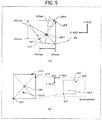
- FIG. 5 illustrates an outline of a method of arranging a drawing figure of the hydraulic breaker 8a and the target-surface figure 48 in the coordinate system on the image on the basis of the positions of the first monitor point MP1, the third link pin 22, the third cylinder pin 44 and the target-surface figure 48 on the work-implement operation plane (X-Z plane).
- a point positioned at the tip of the hydraulic breaker 8a (a point positioned on the contour of hydraulic breaker 8a projected onto the work-implement operation plane (X-Z plane)) is defined as the first monitor point MP1
- a point at which the central axis of the third link pin 22 crosses the working-implement operation plane (X-Z plane) (hereinafter, referred to as a "third-link-pin central point” as appropriate) is defined as a point LP3
- a point at which the central axis of the third cylinder pin 44 crosses the working-implement operation plane (X-Z plane) (hereinafter, referred to as a "third-cylinder-pin central point” as appropriate) is defined as a point CP3.
- the distance between the point MP1 and each of all line segments constituting the target-surface figure 48 is calculated, the line segment closest to the target-surface figure 48 is defined as a nearest line segment TL1, and a first nearest target-surface point TP1 included in the nearest line segment is acquired.
- the maximum value and minimum value, PXmax and PXmin, and the maximum value and minimum value, PZmax and PZmin, on the work-implement operation plane (X-Z plane) along the X axis and the Z axis, respectively, are acquired from the four points which are the point MP1, the point LP3, the point CP3 and the point TP1.
- the scale Ksc1 is obtained from the minimum value of the quotients of the maximum values [pxmax, pymax] of the size of the screen divided by the differences between the maximum values and the minimum values of the four points on the work-implement operation plane (X-Z plane).
- min is an operator for selecting the minimum value from arguments
- ⁇ sc1 is a positive real number
- X-Z plane work-implement operation plane
- the coordinate system of a screen typically has its origin at the upper left of the screen, and has an x axis whose positive direction is the right direction, and a y axis whose positive direction is the downward direction.
- a point Pn on the work-implement operation plane (X-Z plane) (local coordinate system) is converted into a point pn in the coordinate system on the image according to the following formula.
- pn px max / 2 py max / 2 ⁇ Ksc 1 ⁇ Pn ⁇ OP 1
- the point MP1, the point LP3, the point CP3 and the point TP1 of the work-device position and the target-surface figure 48 on the work-implement operation plane (X-Z plane) are converted into a point mp1, a point lp3, a point cp3 and a point tp1, respectively, in the coordinate system on the image according to Formula (3).
- Step S3 the three points which are the point mp1, the point lp3 and the point cp3 indicating the work-device position in the coordinate system on the image calculated at Step S2 are used to perform a process of deforming the drawing figure included in the work-device drawing information which is associated with that the work-device-type information set through the operation section 37 of the display device 19 is about the hydraulic breaker 8a.
- the work-device drawing information which is associated with that the work-device-type information is about the hydraulic breaker 8a includes image information on a first drawing figure 49 (illustrated in FIG. 6(a) ) including the first monitor point MP1, the third-link-pin central point (first coupling point) LP3 and the third-cylinder-pin central point (second coupling point) CP3 of the hydraulic breaker 8a, and the coordinate values of the point mp1a, the point lp3a and the point cp3a indicating the positions of the first monitor point MP1, the third-link-pin central point LP3 and the third-cylinder-pin central point CP3, respectively, in a coordinate system on the first drawing figure 49.
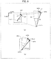
- FIG. 6 illustrates one example of a method of deforming the first drawing figure 49 representing the hydraulic breaker 8a on the basis of work-device dimensional information on the actually attached hydraulic breaker 8a and work-device drawing information indicating the hydraulic breaker 8a.
- Linear mapping is used as a technique for a process of deforming the first drawing figure 49.
- the image deformation matrix A used for linear mapping to deform the first drawing figure 49 can be obtained from the work-device dimensional information on the hydraulic breaker 8a, and information on coordinates on an image plane.
- a vector u1 originating at the point lp3 and terminating at the point cp3 is defined as [u1x, u1y]
- a vector u2 originating at the point lp3 and terminating at the point mp1 is defined as [u2x, u2y]
- a vector v1 originating at the point lp3a and terminating at the point cp3a is defined as [v1x, vly]
- a vector v2 originating at the point lp3a and terminating at the point mp1a is defined as [v2x, v2y].
- Matrixes P1 and Q1 created from the vectors v1 and v2 and the vectors u1 and u2, respectively, are represented by the following formulae.
- P 1 v 1 x v 2 x v 1 y v 2 y
- Q 1 u 1 x u 2 x u 1 y u 2 y
- the case where there is the inverse matrix P1 -1 of the matrix P1 is the case where the matrix P1 is a regular matrix, and in a case where the determinant of the matrix P1 is 0 as an exemplary case where the matrix P1 is decided as not a regular matrix, the process does not proceed to Step S4, but the calculation of the drawing calculating section 40d ends.
- the image deformation matrix A obtained according to Formula (8) is used to deform the first drawing figure 49 of the hydraulic breaker 8a, and create a first post-deformation drawing figure 49a (illustrated in FIG. 6(b) ), and the process proceeds to Step S4.
- Step S4 a drawing image is created on the screen of the display section 38 on the basis of the first post-deformation drawing figure 49a of the hydraulic breaker 8a obtained at Step S3, and the arrangement of the work device 8 and the target-surface figure 48 on a drawing screen obtained from Step S2.
- the first post-deformation drawing figure 49a of the hydraulic breaker 8a is arranged in the drawing image with the three points which are the point mp1a, the point lp3a and the point cp3a (illustrated in FIG. 6(b) ) included in the image being arranged correspondingly to the corresponding three points which are the point mp1, the point lp3 and the point cp3 (illustrated in FIG. 6(a) ) of the work-device position included in the drawing image.
- Formula (3) is applied sequentially to line segments that are included in the target-surface figure 48 in an order starting from the ones adjacent to the nearest line segment TL1, and a range of the target-surface figure 48 in the coordinate system on the image that fits in the screen is drawn.
- the construction machine 1 includes: the work implement 3 having the work device 8 attached pivotably via the first coupling pin 22 and the second coupling pin 44; the display controller 31 that creates a drawing figure representing a side surface of the work device 8 on the basis of drawing information and dimensional information on the work device 8, and creates a target-surface figure representing a target surface on the basis of target-surface information; and the display device 19 that displays the drawing figure and the target-surface figure.
- the dimensional information on the work device 8 includes: positional information on the first coupling point LP3 positioned on the central axis of the first coupling pin 22; positional information on the second coupling point CP3 positioned on the central axis of the second coupling pin 44; and positional information on the first monitor point MP1 positioned on the contour of the work device 8 projected onto an operation plane of the work implement 3.
- the drawing information on the work device 8 includes image information on the first drawing figure 49 representing at least part of the work device 8 including the first coupling point LP3, the second coupling point CP3 and the first monitor point MP1.
- the display controller 31 includes: the posture calculating section 40b that calculates the posture of the work implement 3; the work-device-position calculating section 40c that calculates the coordinate values of each of the first coupling point LP3, the second coupling point CP3 and the first monitor point MP1 in a coordinate system on an image on the display device 19 on the basis of the postural information on the work implement 3 and the dimensional information on the work device 8; and the drawing calculating section 40d that deforms the first drawing figure 49 to create the first post-deformation drawing figure 49a such that a triangle having vertexes at the first coupling point LP3, the second coupling point CP3 and the first monitor point MP1 in the first drawing figure 49 becomes congruent with a triangle having vertexes at the first coupling point LP3, the second coupling point CP3 and the first monitor point MP1 in the coordinate system on the image on the display device 19, the drawing calculating section 40d arranging the first post-deformation drawing figure 49a on a screen of the display device 19 such that
- the first post-deformation drawing figure 49a is created such that the triangle having vertexes at the first coupling point lp3a, the second coupling point cp3a and the first monitor point mp1a in the first drawing figure 49 representing the hydraulic breaker 8a becomes congruent with the triangle having vertexes at the first coupling point 1p3, the second coupling point cp3 and the first monitor point mp1 in the coordinate system on the image on the display device 19, and the first post-deformation drawing figure 49a is arranged on the screen of the display device 19 such that the first coupling point lp3a, the second coupling point cp3a and the first monitor point mp1a in the first post-deformation drawing figure 49a are arranged correspondingly to the first coupling point lp3, the second coupling point cp3 and the first monitor point mp1, respectively, in the coordinate system on the image on the display device 19.
- the hydraulic breaker 8a is illustrated as an example of the work device 8 in the present embodiment, the work device 8 is not limited as long as the work device 8 includes a first monitor point MP1, a third link pin 22 and a third cylinder pin 44, and the hydraulic breaker 8a may be replaced with a single-claw ripper and the like.
- the hydraulic excavator 1 according to a second embodiment of the present invention is explained by using FIG. 7 to FIG. 10 .
- the hydraulic excavator 1 according to the present embodiment includes a bucket as the work device 8.
- Differences from the first embodiment are as follows: as illustrated in FIG. 8(a) , there is at least one monitor point other than the first monitor point MP1 inside a bucket 8b as the work device 8; there is one feature point in terms of the structure of the work device 8; and there are at least two drawing figures to be used in drawing the work device 8.
- the work-device-position calculating section 40c (illustrated in FIG. 3 ) further calculates the positions of second and third monitor points MP2 and MP3 which are in the work device 8 and are points of interest in terms of a work other than the first monitor point MP1, and a feature point in terms of the structure of the work device 8 (hereinafter, referred to as a "first feature point") FP1, the positions being calculated in terms of the work-implement operation plane (X-Z plane) and in terms of the global coordinate system.
- first feature point FP1
- the drawing calculating section 40d creates a guidance image, and outputs the guidance image to the display section 38.
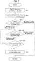
- FIG. 7 is a flowchart illustrating one example of a drawing-calculation process performed by the display controller 31 according to the present embodiment.
- the display controller 31 creates a side surface image (guidance image) illustrating a positional relationship between a target surface and the work device 8 in accordance with the flowchart illustrated in FIG. 7 .
- Step S11 in a similar manner to Step S1 in the first embodiment, the target-surface information is read in from the storage section 41.
- Step S12 the target-surface figure 48 obtained from Step S11, and the work-device position obtained from the work-device-position calculating section 40c are used, and arranged in a coordinate system on an image.
- the scale Ksc1 and the offset OP1 are determined for arranging the entire work device 8 and at least one line segment constituting the target-surface figure 48 such that the entire work device 8 and the at least one line segment are included in the screen.
- FIG. 8 illustrates the outline of a method of arranging a drawing figure of the bucket 8b and the target-surface figure 48 in the coordinate system on the image on the basis of the positions of the first monitor point MP1, the second and third monitor points MP2 and MP3, the first feature point FP1, the third-link-pin central point LP3, the third-cylinder-pin central point CP3 and the target-surface figure 48 on the work-implement operation plane (X-Z plane).
- a point positioned at the tip of the bucket 8b (a point positioned on the contour of the bucket 8b projected onto the work-implement operation plane (X-Z plane)) is defined as the first monitor point MP1
- points positioned on the rear surface of the bucket 8b are defined as the second and third monitor points MP2 and MP3.
- an end point of a joint between a member for attaching the bucket 8b to the arm 7 and to the third cylinder 11 and a member to serve as a rear plate of the bucket 8b is defined as the first feature point FP1.
- the distance between the point MP1 and each of all line segments constituting the target-surface figure 48 is calculated, the line segment closest to the target-surface figure 48 is defined as the nearest line segment TL1, and the first nearest target-surface point TP1 included in the nearest line segment is acquired.
- the maximum value and minimum value, PXmax and PXmin, and the maximum value and minimum value, PZmax and PZmin, on the work-implement operation plane (X-Z plane) along the X axis and the Z axis, respectively, are acquired from the seven points which are the point MP1, the point MP2, the point MP3, the point FP1, the point LP3, the point CP3 and the point TP1.
- the offset OP1 is calculated according to Formula (1) such that the center of the acquired maximum values and minimum values of the seven points is located at the origin.
- the scale Ksc1 is obtained from the minimum value of the quotients of the maximum values [pxmax, pymax] of the size of the screen divided by the differences between the maximum values and the minimum values of the seven points on the work-implement operation plane (X-Z plane).
- the scale Ksc1 is calculated according to Formula (2).
- the point MP1, the point MP2, the point MP3, the point FP1, the point LP3, the point CP3 and the point TP1 of the work-device position and the target-surface figure 48 on the work-implement operation plane (X-Z plane) (local coordinate system) are converted into the point mp1, the point mp2, the point mp3, the point fp1, the point lp3, the point cp3 and the point tp1, respectively, in the coordinate system on the image according to Formula (3).
- the three points which are the point mp1, the point lp3 and the point cp3 indicating the work-device position in the coordinate system on the image calculated at Step S12 are used to perform a process of deforming a first drawing figure 53 included in the work-device drawing information which is associated with that the work-device-type information set through the operation section 37 of the display device 19 is about the bucket 8b.
- the work-device drawing information which is associated with that the work-device-type information is about the bucket 8b includes image information on the first drawing figure 53 including the first monitor point MP1, the third-link-pin central point LP3 and the third-cylinder-pin central point CP3 of the bucket 8b, and the coordinate values of the point mp1a, the point lp3a and the point cp3a indicating the positions of the first monitor point MP1, the third-link-pin central point LP3 and the third-cylinder-pin central point CP3, respectively, in a coordinate system on the first drawing figure 53.
- FIG. 9 illustrates one example of a method of deforming the first drawing figure 53 of the bucket 8b on the basis of work-device dimensional information on the actually attached bucket 8b and work-device drawing information indicating the bucket 8b.
- linear mapping is used as a technique for a process of deforming the first drawing figure 53.
- Linear mapping is represented by Formula (4).
- the image deformation matrix A1 used for linear mapping to convert the first drawing figure 53 can be obtained from the work-device dimensional information on the bucket 8b, and information on positions at coordinates of the first drawing figure 53.
- a vector u1 originating at the point lp3 and terminating at the point cp3 is defined as [u1x, u1y]
- a vector u2 originating at the point lp3 and terminating at the point mp1 is defined as [u2x, u2y]
- a vector v1 originating at the point lp3a and terminating at the point cp3a is defined as [v1x, v1y]
- a vector v2 originating at the point lp3a and terminating at the point mp1a is defined as [v2x, v2y].
- the image deformation matrix A1 is represented by Formulae (5) to (8) .
- the case where there is the inverse matrix P1 -1 of the matrix P1 is the case where the matrix P1 is a regular matrix, and in a case where the determinant of the matrix P1 is 0 as an exemplary case where the matrix P1 is decided as not a regular matrix, the process does not proceed to Step S14, but the calculation of the drawing calculating section 40d ends.
- the image deformation matrix A1 obtained according to Formula (8) is used to deform the first drawing figure 53 of the bucket 8b, and create a first post-deformation drawing figure 53a (illustrated in FIG. 9(b) or FIG. 10 ), and the process proceeds to Step S14.
- the point mp(k), the point mp(k + 1) and the point fp1 indicating the work-device position in the coordinate system on the image that are calculated at Step S12, that is, the three points which are mp1, the point mp2 and the point fp1 since the number of times of loop k is 1, are used to perform a process of deforming a second drawing figure 54 included in the work-device drawing information which is associated with that the work-device-type information set through the operation section 37 of the display device 19 is about the bucket 8b.
- the work-device drawing information which is associated with that the work-device-type information is about the bucket 8b includes image information on the second drawing figure 54 which is a triangle having vertexes at the first monitor point MP1, the second monitor point MP2 and the first feature point FP1 of the bucket 8b, and the coordinate values of the point mp1b, the point mp2b and the point fp1b indicating the positions of the first monitor point MP1, the second monitor point MP2 and the first feature point FP1, respectively, in a coordinate system on the second drawing figure 54.
- the second drawing figure 54 is deformed such that a triangle linking the point mp1, the point mp2 and the point fp1 becomes congruent with a triangle which is the second drawing figure 54 to create a second post-deformation drawing figure 54a (illustrated in FIG. 10 ), and the process proceeds to Step S15.
- the point mp(k), the point mp(k + 1) and the point fp1 indicating the work-device position in the coordinate system on the image that are calculated at Step S12, that is, the three points which are the point mp2, the point mp3 and the point fp1 since the number of times of loop k is 2, are used to perform a process of deforming a third drawing figure 55 included in the work-device drawing information which is associated with that the work-device-type information set through the operation section 37 of the display device 19 is about the bucket 8b.
- the work-device drawing information which is associated with that the work-device-type information is about the bucket 8b includes image information on the third drawing figure 55 which is a triangle having vertexes at the second monitor point MP2, the third monitor point MP3 and the first feature point FP1 of the bucket 8b, and the coordinate values of the point mp2c, the point mp3c and the point fp1c indicating the positions of the second monitor point MP2, the third monitor point MP3 and the first feature point FP1, respectively, in a coordinate system on the third drawing figure 55.
- the case where there is a triangle is the case where all of the point mp2c, the point mp3c and the point fp1c which are three points constituting the triangle are not collinear, and in a case where the three points are collinear, the process does not proceed to Step S15, but the calculation of the drawing calculating section 40d ends.
- the three points are not collinear, as a process of deforming the third drawing figure 55, the third drawing figure 55 is deformed such that a triangle linking the point mp2, the point mp3 and the point fp1 becomes congruent with a triangle which is the third drawing figure 55 to create a third post-deformation drawing figure 55a (illustrated in FIG. 10 ), and the process proceeds to Step S17.
- Step S17 a continuation decision about the loop continuing from Step S14 is made.
- the loop processing ends, and the process proceeds to Step S18.
- Step S18 a drawing image is created on the screen of the display section 38 on the basis of the first to third post-deformation drawing figures 53a to 55a of the bucket 8b obtained at Steps S13, S14 and S16, and the arrangement of the work device 8 and the target-surface figure 48 on a drawing screen obtained from Step S12.
- FIG. 10 illustrates a state where the first to third post-deformation drawing figures 53a to 55a representing the bucket 8b are arranged in the drawing image.
- the first post-deformation drawing figure 53a of the bucket 8b is arranged in the drawing image with the three points which are the point mp1a, the point lp3a and the point cp3a included in the image being arranged correspondingly to the corresponding three points which are the point mp1, the point lp3 and the point cp3 of the work-device position included in the drawing image.
- the second post-deformation drawing figure 54a of the bucket 8b is arranged in the drawing image with the three points which are the point mp1b, the point mp2b and the point fp1b included in the image being arranged correspondingly to the corresponding three points which are the point mp1, the point mp2 and the point fp1 of the work-device position included in the drawing image.
- the third post-deformation drawing figure 55a of the bucket 8b is arranged in the drawing image with the three points which are the point mp2c, the point mp3c and the point fp1c included in the image being arranged correspondingly to the corresponding three points which are the point mp2, the point mp3 and the point fp1 of the work-device position included in the drawing image.
- a range of the image of the target-surface figure 48 that fits in the screen is drawn, in a similar manner to the first embodiment.
- the work device 8 is a bucket
- the first monitor point MP1 is positioned at the tip of the bucket 8
- the dimensional information on the work device 8 further includes positional information on the first monitor point MP1, the second monitor point MP2 at a position on the rear surface of the bucket 8, and the first feature point FP1 at another position on the rear surface of the bucket 8.
- the drawing information on the work device 8 further includes image information on the second drawing figure 54 representing part of the work device 8 including the first monitor point MP1, the second monitor point MP2 and the first feature point FP1.
- the work-device-position calculating section 40c calculates the coordinate values of each of the second monitor point MP2 and the first feature point FP1 on the basis of the dimensional information on the work device 8, and the drawing calculating section 40d deforms the second drawing figure 54 to create the second post-deformation drawing figure 54a such that a triangle having vertexes at the first monitor point MP1, the second monitor point MP2 and the first feature point FP1 in the second drawing figure 54 becomes congruent with a triangle having vertexes at the first monitor point MP1, the second monitor point MP2 and the first feature point FP1 in the coordinate system on the image on the display device 19, and arranges the second post-deformation drawing figure 54a on the screen of the display device 19 such that the positions of the first monitor point MP1, the second monitor point MP2 and the first feature point FP1 in the second drawing figure 54 are arranged correspondingly to the positions of the first monitor point MP1, the second monitor point MP2 and the first feature point FP1, respectively, in the coordinate system on the image on the display device
- the dimensional information on the work device 8 further includes positional information on the second monitor point MP2, the first feature point FP1 and the third monitor point MP3 at a position on the rear surface of the bucket 8
- the drawing information on the work device 8 further includes image information on the third drawing figure 55 representing part of the work device 8 including the second monitor point MP2, the third monitor point MP3 and the first feature point FP1
- the work-device-position calculating section 40c calculates the coordinate values of the third monitor point MP3 on the basis of the dimensional information on the work device 8, and the drawing calculating section 40d deforms the third drawing figure 55 to create the third post-deformation drawing figure 55a such that a triangle having vertexes at the second monitor point MP2, the third monitor point MP3 and the first feature point FP1 in the third drawing figure 55 becomes congruent with a triangle having vertexes at the second monitor point MP2, the third monitor point MP3 and the first feature point FP1 in the coordinate system on the image on the display device 19, and arranges the third post-deformation
- the work device 8 is not limited as long as the work device 8 includes a plurality of monitor points, a third link pin 22 and a third cylinder pin 44, and the bucket 8b may be replaced with a magnet and the like.
- the number of monitor points is three in the case illustrated as an example in the present embodiment, the number of monitor points may be any number as long as it is two or larger, and the number is not limited.
- linear mapping may be used in a similar manner to the first drawing figure 53.
- Step S18 represent the image with smooth lines like the bottom surface 56 (a section indicated by broken lines) of the bucket 8b illustrated in FIG. 10 by using a spline curve passing through points including any monitor point and the first feature point FP1, and filling regions between the spline curve and the second and third drawing figures 54 and 55 with paint.
- the hydraulic excavator 1 according to a third embodiment of the present invention is explained by using FIG. 11 to FIG. 14 .
- the hydraulic excavator 1 according to the present embodiment includes a secondary crusher as the work device 8.
- a secondary crusher 8c as the work device 8 has a work-device frame (base portion) 57 and a work-device arm (first driven portion) 58, the work-device frame 57 includes therein the first monitor point MP1, and the work-device arm 58 includes therein the second monitor point MP2; the second monitor point MP2 exhibits a rotational movement about the first feature point FP1 in terms of the structure included in the work-device frame 57; and two drawing figures of the work device 8 are included.
- the work-device arm 58 is pivotably connected to the work-device frame 57 via a fourth link pin (third coupling pin) 59, and is driven by a fourth cylinder 63. That is, the first feature point FP1 is a point on the central axis of the fourth link pin 59.
- a fourth rotation-angle sensor 64 is attached to the work-device arm 58.
- the fourth rotation-angle sensor 64 is an IMU, for example, which is attached to the work-device arm 58, senses the angle around the fourth link pin 59 formed between the work-device arm 58 and the vertical (gravity) direction, and outputs the angle of the work-device arm 58 relative to the work-device frame 57.
- the posture calculating section 40b calculates an angle ⁇ 4 around the fourth link pin 59 of the work-device arm 58 relative to the work-device frame 57.
- the work-device-position calculating section 40c (illustrated in FIG. 3 ) further calculates the positions of the second monitor point MP2 included in the work-device arm 58, and the first feature point FP1 in terms of the structure included in the work-device frame 57, the positions being calculated in terms of the work-implement operation plane (X-Z plane) and in terms of the global coordinate system.
- the drawing calculating section 40d creates a guidance image.
- FIG. 11 is a flowchart illustrating one example of a drawing-calculation process performed by the display controller 31 according to the present embodiment.
- the display controller 31 creates a side surface image (guidance image) illustrating a positional relationship between a target surface and the work device 8 in accordance with the flowchart illustrated in FIG. 11 .
- Step S21 in a similar manner to Step S1 in the first embodiment, the target-surface information is read in from the storage section 41.
- Step S22 the target-surface figure 48 obtained from Step S21, and the work-device position obtained from the work-device-position calculating section 40c are used, and arranged in a coordinate system on an image.
- the scale Ksc1 and the offset OP1 are determined for arranging the entire work device 8 and at least one line segment constituting the target-surface figure 48 such that the entire work device 8 and the at least one line segment are included in the screen.
- FIG. 12 illustrates the outline of a method of arranging a drawing figure of the secondary crusher 8c and the target-surface figure 48 in the coordinate system on the image on the basis of the positions of the first monitor point MP1, the second monitor point MP2, the first feature point FP1, the third-link-pin central point LP3, the third-cylinder-pin central point CP3 and the target-surface figure 48 on the work-implement operation plane (X-Z plane).
- a point positioned at the tip of the work-device frame 57 (a point positioned on the contour of the work-device frame 57 projected onto the work-implement operation plane (X-Z plane)) is defined as the first monitor point MP1
- a point positioned at the tip of the work-device arm 58 (a point positioned on the contour of the work-device arm 58 projected onto the work-implement operation plane (X-Z plane)) is defined as the second monitor point MP2
- a point at which the central axis of the fourth link pin 59 pivotably coupling the work-device arm 58 to the work-device frame 57 crosses the working-implement operation plane (X-Z plane) is defined as the first feature point FP1.
- the distance between the point MP1 and each of all line segments constituting the target-surface figure 48 is calculated, the line segment closest to the target-surface figure 48 is defined as the nearest line segment TL1, and the first nearest target-surface point TP1 included in the nearest line segment is acquired.
- the maximum value and minimum value, PXmax and PXmin, and the maximum value and minimum value, PZmax and PZmin, on the work-implement operation plane (X-Z plane) along the X axis and the Z axis, respectively, are acquired from the six points which are the point MP1, the point MP2, the point FP1, the point LP3, the point CP3 and the point TP1.
- the offset OP1 is calculated according to Formula (1) such that the center of the acquired maximum values and minimum values of the six points is located at the origin.
- the scale Kscl is obtained from the minimum value of the quotients of the maximum values [pxmax, pymax] of the size of the screen divided by the differences between the maximum values and the minimum values of the six points on the work-implement operation plane (X-Z plane).
- the scale Ksc1 is calculated according to Formula (2).
- the point MP1, the point MP2, the point FP1, the point LP3, the point CP3 and the point TP1 of the work-device position and the target-surface figure 48 on the work-implement operation plane (X-Z plane) (local coordinate system) are converted into the point mp1, the point mp2, the point fp1, the point lp3, the point cp3 and the point tp1 in the coordinate system on the image according to Formula (3).
- the three points which are the point mp1, the point lp3 and the point cp3 indicating the work-device position in the coordinate system on the image calculated at Step S22 are used to perform a process of deforming a first drawing figure 65 included in the work-device drawing information which is associated with that the work-device-type information set through the operation section 37 of the display device 19 is about the secondary crusher 8c.
- the work-device drawing information which is associated with that the work-device-type information is about the secondary crusher 8c includes image information on the first drawing figure 65 including the three points which are the first monitor point MP1, the third-link-pin central point LP3 and the third-cylinder-pin central point CP3 of the secondary crusher 8c, and the coordinate values of the point mp1a, the point lp3a and the point cp3a indicating the positions of the first monitor point MP1, the third-link-pin central point LP3 and the third-cylinder-pin central point CP3, respectively, in a coordinate system on the first drawing figure 65.
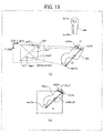
- FIG. 13 illustrates one example of a method of deforming the first drawing figure 65 representing part (the work-device frame 57) of the secondary crusher 8c on the basis of work-device dimensional information on the actually attached secondary crusher 8c and work-device drawing information indicating the secondary crusher 8c.
- linear mapping is used as a technique for a process of deforming the first drawing figure 65.
- Linear mapping is represented by Formula (4).
- the image deformation matrix A1 used for linear mapping to convert the first drawing figure 65 can be obtained from the work-device dimensional information on the secondary crusher 8c, and information on positions at coordinates of the first drawing figure 65.
- a vector u1 originating at the point lp3 and terminating at the point cp3 is defined as [u1x, u1y]
- a vector u2 originating at the point lp3 and terminating at the point mp1 is defined as [u2x, u2y]
- a vector v1 originating at the point lp3a and terminating at the point cp3a is defined as [v1x, v1y]
- a vector v2 originating at the point lp3a and terminating at the point mp1a is defined as [v2x, v2y].
- the image deformation matrix A1 is represented by Formulae (5) to (8) .
- the case where there is the inverse matrix P1 -1 of the matrix P1 is the case where the matrix P1 is a regular matrix, and in a case where the determinant of the matrix P1 is 0 as an exemplary case where the matrix P1 is decided as not a regular matrix, the process does not proceed to Step S24, but the calculation of the drawing calculating section 40d ends.
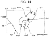
- the image deformation matrix A1 obtained according to Formula (8) is used to deform the first drawing figure 65 of the secondary crusher 8c, and create a first post-deformation drawing figure 65a (illustrated in FIG. 13(b) or FIG. 14 ), and the process proceeds to Step S24.
- Step S24 the two points which are the point mp2 and the point fp1 indicating the work-device position in the coordinate system on the image calculated at Step S22 are used to perform a process of deforming a second drawing figure 66 included in the work-device drawing information which is associated with that the work-device-type information set through the operation section 37 of the display device 19 is about the secondary crusher 8c.
- the work-device drawing information which is associated with that the work-device-type information is about the secondary crusher 8c includes image information on the second drawing figure 66 including the two points which are the second monitor point MP2 and the first feature point FP1 of the secondary crusher 8c, and the coordinate values of the point mp2b and the point fp1b indicating the positions of the second monitor point MP2 and the first feature point FP1, respectively, in a coordinate system on the second drawing figure 66.
- the length of a line segment linking the point mp2b and the point fp1b is divided by the length of a line segment linking the point mp2 and the point fp1, and the quotient is used for reducing or increasing the size of the second drawing figure 66 such that the aspect ratio of the second drawing figure 66 remains unchanged to create a second post-deformation drawing figure 66a (illustrated in FIG. 14 ).
- Step S25 a drawing image is created on the screen of the display section 38 on the basis of the first and second post-deformation drawing figures 65a and 66a of the secondary crusher 8c obtained at Steps S23 and S24, and the arrangement of the work device 8 and the target-surface figure 48 on a drawing screen obtained from Step S22.
- FIG. 14 illustrates a state where the first and second post-deformation drawing figures 65a and 66a representing the secondary crusher 8c are arranged in the drawing image.
- the first post-deformation drawing figure 65a of the secondary crusher 8c is arranged in the drawing image with the three points which are the point mp1a, the point lp3a and the point cp3a included in the image being arranged correspondingly to the corresponding three points which are the point mp1, the point lp3 and the point cp3 of the work-device position included in the drawing image.
- the second post-deformation drawing figure 66a of the secondary crusher 8c is arranged in the drawing image with the two points which are the point mp2b and the point fp1b included in the image being arranged correspondingly to the corresponding two points which are the point mp2 and the point fp1 of the work-device position included in the drawing image.
- a range of the image of the target-surface figure 48 that fits in the screen is drawn, in a similar manner to the first embodiment.
- the work device 8 has the base portion 57 including the first coupling point LP3, the second coupling point CP3 and the first monitor point MP1, and the first driven portion 58 attached pivotably to the base portion 57 via the third coupling pin 59
- the construction machine 1 further includes the first posture sensor 64 that senses the posture of the first driven portion 58
- the dimensional information on the work device 8 further includes positional information on the first feature point FP1 positioned on the central axis of the third coupling pin 59 and the second monitor point MP2 positioned at the tip of the first driven portion 58
- the drawing information on the work device 8 further includes image information on the second drawing figure 66 representing the first driven portion 58 including the first feature point FP1 and the second monitor point MP2
- the work-device-position calculating section 40c calculates the coordinate values of each of the first feature point FP1 and the second monitor point MP2 on the basis of the dimensional information on the work device 8 and the posture of the first driven portion 58 sensed by the first posture sensor
- the secondary crusher 8c is illustrated as an example of the work device 8 in the present embodiment, the work device 8 is not limited as long as the work device 8 includes: a base portion including the third link pin 22, the third cylinder pin 44 and at least one monitor point; a driven portion that includes at least one monitor point, and pivots about one certain point, and a drive portion for the driven portion; and the secondary crusher 8c may be replaced with a hydraulic pressure cutter and the like with the same structure.
- first drawing figure 65 which is an image of the base portion including the third link pin 22, the third cylinder pin 44 and at least one monitor point of the work device 8
- second drawing figure 66 which is an image of a driven portion that includes at least one monitor point and pivots about one certain point
- a drive portion such as a hydraulic cylinder may be drawn further, for example.
- the hydraulic excavator 1 according to a fourth embodiment of the present invention is explained by using FIG. 15 to FIG. 18 .
- the hydraulic excavator 1 according to the present embodiment includes a primary crusher as the work device 8.
- a primary crusher 8d as the work device 8 has one work-device frame (base portion) 67 and a pair of first and second work-device arms (first and second driven portions) 68 and 69, the work-device frame 67 includes therein the first monitor point MP1, and the first and second work-device arms 68 and 69 include the second and third monitor points MP2 and MP3, respectively; the second monitor point MP2 exhibits a rotational movement about the first feature point FP1 in terms of the structure included in the work-device frame 67, and the third monitor point MP3 exhibits a rotational movement about a second feature point FP2 in terms of the structure included in the work-device frame 67; and three drawing figures to be used in drawing the work device 8 are included.
- the first work-device arm 68 is pivotably connected to the work-device frame 67 via a fourth link pin 75, and is driven by a fourth cylinder 76.
- the second work-device arm 69 is pivotably connected to the work-device frame 67 via a fifth link pin (fourth coupling pin) 77, and is driven by a fifth cylinder 78. That is, the first feature point FP1 is a point on the central axis of the fourth link pin 75, and the second feature point FP2 is a point on the central axis of the fifth link pin 77.
- fourth and fifth rotation-angle sensors 79 and 80 are attached to the first and second work-device arms 68 and 69.
- the fourth and fifth rotation-angle sensors 79 and 80 are IMUs, for example, which are attached to the first and second work-device arms 68 and 69, respectively, sense the angle around the fourth link pin 75 formed between the first work-device arm 68 and the vertical (gravity) direction, and the angle around the fifth link pin 77 formed between the second work-device arm 69 and the vertical (gravity) direction, and output the angle of the first work-device arm 68 relative to the work-device frame 67, and the angle of the second work-device arm 69 relative to the work-device frame 67, respectively.
- the posture calculating section 40b calculates angles ⁇ 4 and ⁇ 5 around the fourth and fifth link pins 75 and 77 of the first and second work-device arms 68 and 69 relative to the work-device frame 67.
- the work-device-position calculating section 40c (illustrated in FIG. 3 ) further calculates the positions of the second and third monitor points MP2 and MP3 included in the first and second work-device arms 68 and 69, and the first and second feature points FP1 and FP2 in terms of the structure included in the work-device frame 67, the positions being calculated in terms of the work-implement operation plane (X-Z plane) and in terms of the global coordinate system.
- the drawing calculating section 40d creates a guidance image.
- FIG. 15 is a flowchart illustrating one example of a drawing-calculation process performed by the display controller 31 according to the present embodiment.
- the display controller 31 creates a side surface image (guidance image) illustrating a positional relationship between a target surface and the work device 8 in accordance with the flowchart illustrated in FIG. 15 .
- Step S31 in a similar manner to Step S1 in the first embodiment, the target-surface information is read in from the storage section 41.
- Step S32 the target-surface figure 48 obtained from Step S31, and the work-device position obtained from the work-device-position calculating section 40c are used and arranged in a coordinate system on an image.
- the scale Ksc1 and the offset OP1 are determined for arranging the entire work device 8 and at least one line segment constituting the target-surface figure 48 such that the entire work device 8 and the at least one line segment are included in the screen.
- FIG. 16 illustrates the outline of a method of arranging a drawing figure of the primary crusher 8d and the target-surface figure 48 in the coordinate system on the image on the basis of the positions of the first to third monitor points MP1 to MP3, the first and second feature points FP1 and FP2, the third-link-pin central point LP3, the third-cylinder-pin central point CP3 and the target-surface figure 48 on the work-implement operation plane (X-Z plane).
- a point positioned at the tip of the work-device frame 67 (a point positioned on the contour of the work-device frame 67 projected onto the work-implement operation plane (X-Z plane)) is defined as the first monitor point MP1
- points positioned at the tips of the first and second work-device arms 68 and 69, respectively are defined as the second and third monitor points MP2 and MP3, respectively
- a point at which the central axis of the fourth link pin 75 pivotably coupling the first work-device arm 68 to the work-device frame 67 crosses the working-implement operation plane (X-Z plane) is defined as the first feature point FP1
- the distance between each of the point MP1, the point MP2 and the point MP3, and each of all line segments constituting the target-surface figure 48 is calculated, the line segment closest to the target-surface figure 48 is defined as the nearest line segment TL1, and the first nearest target-surface point TP1 included in the nearest line segment is acquired.
- the maximum value and minimum value, PXmax and PXmin, and the maximum value and minimum value, PZmax and PZmin, on the work-implement operation plane (X-Z plane) along the X axis and the Z axis, respectively, are acquired from the eight points which are the point MP1, the point MP2, the point MP3, the point FP1, the point FP2, the point LP3, the point CP3 and the point TP1.
- the offset OP1 is calculated according to Formula (1) such that the center of the acquired maximum values and minimum values of the eight points is located at the origin.
- the scale Ksc1 is obtained from the minimum value of the quotients of the maximum values [pxmax, pymax] of the size of the screen divided by the differences between the maximum values and the minimum values of the eight points on the work-implement operation plane (X-Z plane).
- the scale Ksc1 is calculated according to Formula (2).
- the point MP1, the point MP2, the point MP3, the point FP1, the point FP2, the point LP3, the point CP3 and the point TP1 of the work-device position and the target-surface figure 48 on the work-implement operation plane (X-Z plane) (local coordinate system) are converted into the point mp1, the point mp2, the point mp3, the point fp1, the point fp2, the point lp3, the point cp3 and the point tp1, respectively, in the coordinate system on the image according to Formula (3).
- Step S33 the three points which are the point mp1, the point lp3 and the point cp3 indicating the work-device position in the coordinate system on the image calculated at Step S32 are used to perform a process of deforming a first drawing figure 81 included in the work-device drawing information which is associated with that the work-device-type information set through the operation section 37 of the display device 19 is about the primary crusher 8d.
- the work-device drawing information which is associated with that the work-device-type information is about the primary crusher 8d includes image information on the first drawing figure 81 including the first monitor point MP1, the third-link-pin central point LP3 and the third-cylinder-pin central point CP3, and representing part of the primary crusher 8d, and the coordinate values of the point mp1a, the point lp3a and the point cp3a indicating the positions of the first monitor point MP1, the third-link-pin central point LP3 and the third-cylinder-pin central point CP3, respectively, in a coordinate system on the first drawing figure 81.
- FIG. 17 illustrates one example of a method of deforming the first drawing figure 81 representing part (the work-device frame 67) of the primary crusher 8d on the basis of work-device dimensional information on the actually attached primary crusher 8d and work-device drawing information indicating the primary crusher 8d.
- linear mapping is used as a technique for a process of deforming the first drawing figure 81.
- Linear mapping is represented by Formula (4).
- the image deformation matrix A1 used for linear mapping to convert the first drawing figure 81 can be obtained from the work-device dimensional information on the primary crusher 8d, and information on positions at coordinates of the first drawing figure 81.
- a vector u1 originating at the point lp3 and terminating at the point cp3 is defined as [u1x, u1y]
- a vector u2 originating at the point lp3 and terminating at the point mp1 is defined as [u2x, u2y]
- a vector v1 originating at the point lp3a and terminating at the point cp3a is defined as [v1x, vly]
- a vector v2 originating at the point lp3a and terminating at the point mp1a is defined as [v2x, v2y].
- the image deformation matrix A1 is represented by Formulae (5) to (8).
- the case where there is the inverse matrix P1 -1 of the matrix P1 is the case where the matrix P1 is a regular matrix, and in a case where the determinant of the matrix P1 is 0 as an exemplary case where the matrix P1 is decided as not a regular matrix, the process does not proceed to Step S34, but the calculation of the drawing calculating section 40d ends.
- the image deformation matrix A1 obtained according to Formula (8) is used to deform the first drawing figure 81 of the primary crusher 8d, and create a first post-deformation drawing figure 81a (illustrated in FIG. 17(b) or FIG. 18 ), and the process proceeds to Step S34.
- Step S34 the two points which are the point mp2 and the point fp1 indicating the work-device position in the coordinate system on the image calculated at Step S32 are used to perform a process of deforming a second drawing figure 82 included in the work-device drawing information which is associated with that the work-device-type information set through the operation section 37 of the display device 19 is about the primary crusher 8d.
- the work-device drawing information which is associated with that the work-device-type information is about the primary crusher 8d includes image information on the second drawing figure 82 including the two points which are the second monitor point MP2 and the first feature point FP1 of the primary crusher 8d, and the coordinate values of the point mp2b and the point fp1b indicating the positions of the second monitor point MP2 and the first feature point FP1, respectively, in a coordinate system on the second drawing figure 82.
- the length of a line segment linking the point mp2b and the point fp1b is divided by the length of a line segment linking the point mp2 and the point fp1, and the quotient is used for reducing or increasing the size of the second drawing figure 82 such that the aspect ratio of the second drawing figure 82 remains unchanged.
- Step S35 the two points which are the point mp3 and the point fp2 indicating the work-device position in the coordinate system on the image calculated at Step S32 are used to perform a process of deforming a third drawing figure 83 included in the work-device drawing information which is associated with that the work-device-type information set through the operation section 37 of the display device 19 is about the primary crusher 8d.
- the work-device drawing information which is associated with that the work-device-type information is about the primary crusher 8d includes image information on the third drawing figure 83 including the two points which are the third monitor point MP3 and the second feature point FP2 of the primary crusher 8d, and the coordinate values of the point mp3c and the point fp2c indicating the positions of the third monitor point MP3 and the second feature point FP2, respectively, in a coordinate system on the third drawing figure 83.
- the length of a line segment linking the point mp3c and the point fp2c is divided by the length of a line segment linking the point mp3 and the point fp2, and the quotient is used for reducing or increasing the size of the third drawing figure 83 such that the aspect ratio of the third drawing figure 83 remains unchanged.
- Step S36 a drawing image is created on the screen of the display section 38 on the basis of the first to third post-deformation drawing figures 81a to 83a of the primary crusher 8d obtained at Steps S33, S34 and S35, and the arrangement of the work device 8 and the target-surface figure 48 on a drawing screen obtained from Step S32.
- FIG. 18 illustrates a state where the first to third post-deformation drawing figures 81a to 83a representing the primary crusher 8d are arranged in the drawing image.
- the first post-deformation drawing figure 81a of the primary crusher 8d is arranged in the drawing image with the three points which are the point mp1a, the point lp3a and the point cp3a (illustrated in FIG. 17(a) ) included in the image being arranged correspondingly to the corresponding three points which are the point mp1, the point lp3 and the point cp3 (illustrated in FIG. 17(a) ) of the work-device position included in the drawing image.
- the second post-deformation drawing figure 82a of the primary crusher 8d is arranged in the drawing image with the two points which are the point mp2b and the point fp1b included in the drawing figure being arranged correspondingly to the corresponding two points which are the point mp2 and the point fp1 of the work-device position included in the drawing image.
- the third post-deformation drawing figure 83a of the primary crusher 8d is arranged in the drawing image with the two points which are the point mp3c and the point fp2c included in the drawing figure being arranged correspondingly to the corresponding two points which are the point mp3 and the point fp2 of the work-device position included in the drawing image.
- a range of the image of the target-surface figure 48 that fits in the screen is drawn, in a similar manner to the first embodiment.
- the work device 8 further has the second driven portion 69 attached pivotably to the base portion 67 via the fourth coupling pin 77
- the construction machine 1 further includes the second posture sensor 80 that senses the posture of the second driven portion 69
- the dimensional information on the work device 8 further includes positional information on the second feature point FP2 positioned on the central axis of the fourth coupling pin 77 and the third monitor point MP3 positioned at the tip of the second driven portion 69
- the drawing information on the work device 8 further includes image information on the third drawing figure 83 representing the second driven portion 69 including the second feature point FP2 and the third monitor point MP3
- the work-device-position calculating section 40c calculates the coordinate values of each of the first feature point FP1 and the third monitor point MP3 on the basis of the dimensional information on the work device 8 and the posture of the second driven portion 69 sensed by the second posture sensor 80
- the drawing calculating section 40d deforms the third drawing figure 83 to create the third post-deformation drawing figure
- the primary crusher 8d is illustrated as an example of the work device 8 in the present embodiment, the work device 8 is not limited as long as the work device 8 includes a base portion including the third link pin 22, the third cylinder pin 44 and at least one monitor point, two driven portions each of which includes at least one monitor point, and pivots about one certain point, and a drive portion for the driven portion, and the primary crusher 8d may be replaced with a grapple and the like.
- first drawing figure 81 which is an image of the base portion including the third link pin 22, the third cylinder pin 44 and at least one monitor point of the work device 8
- second and third drawing figures 82 and 83 which are images of two driven portions that include at least one monitor point and pivots about one certain point
- a drive portion such as a hydraulic cylinder may be drawn, for example.
- the hydraulic excavator 1 according to a fifth embodiment of the present invention is explained by using FIG. 19 to FIG. 21 .
- the hydraulic excavator 1 according to the present embodiment includes a bucket as the work device 8 in a similar manner to the second embodiment.
- FIG. 19 is a block diagram illustrating the configuration of the calculating section 40 of the display controller 31 according to the present embodiment.
- the calculating section 40 of the display controller 31 further has a monitor-point-setting calculating section 40e.
- the monitor-point-setting calculating section 40e sets information on the dimension of at least one monitor point other than the first monitor point MP1.
- FIG. 20 is a flowchart illustrating one example of a monitor-point-setting-calculation process performed by the display controller 31 according to the present embodiment.
- the display controller 31 sets the unset dimensional information on the monitor points in accordance with the flowchart illustrated in FIG. 20 .
- Step S41 in response to reception of a signal to start a setting-calculation process for a monitor point from the operation section 37, it is displayed on the display section 38 that the first monitor point MP1 should be caused to touch a fixed mark 86 that does not move even if the fixed mark 86 is contacted by the work device 8.
- Step S42 in response to reception of a signal, from the operation section 37, the signal indicating that an operator has checked that the first monitor point MP1 and the mark 86 are in contact with each other, the work-device-position calculating section 40c calculates the position of the first monitor point MP1 on the work-implement operation plane (X-Z plane), stores, in the storage section 41, a position [Xmpla, Zmp1a] of the mark 86 in contact with the first monitor point MP1, and displays, on the display section 38, a warning that nothing other than the work implement 3 should be moved during the subsequent operation until the setting-calculation process for the monitor point ends, in order for the positional relationship between the mark 86 and the center of the first link pin 20, which is the origin, to remain unchanged.
- X-Z plane work-implement operation plane
- Step S43 a setting process for at least one monitor point other than the first monitor point MP1, a k-th monitor point (the initial value of k is 2) is started.
- Monitoring by the operation-amount sensing section of the machine-body operation device 18 is started, and in a case where operation to drive the swing motor 13 or the travel motor 16a or 16b is sensed, the process ends without setting a monitor point.
- the set monitor point is stored in the storage section 41, and the process ends.
- Step S44 it is displayed on the display section 38 that a k-th monitor point, here a point inside the work device 8 that is to be set as the second monitor point MP2, should be caused to touch the mark 86.
- Step S45 in response to reception of a signal, from the operation section 37, the signal indicating that the operator has checked that the second monitor point MP2 and the mark 86 are in contact with each other, the work-device-position calculating section 40c calculates the positions of the third-link-pin central point LP3 and the first monitor point MP1 on the work-implement operation plane (X-Z plane), and stores, in the storage section 41, the position [Xlp3b, Zlp3b] of the third-link-pin central point LP3, and the position [Xmplb, Zmplb] of the first monitor point MP1.
- Step S46 on the basis of the position of the mark 86 stored at Step S42, and the positions of the third link pin LP3 and the first monitor point MP1 stored at Step S45, the position of the second monitor point MP2 inside the work device 8 is calculated.
- the work device 8 in a case where the position of the first monitor point MP1 is aligned with the position of the fixed mark 86 is indicated by broken lines, and the work device 8 in a case where the position of the second monitor point MP2 is aligned with the position of the mark 86 is indicated by solid lines.
- the vector originating at the third-link-pin central point LP3 and terminating at the first monitor point MP1 is defined as w1
- the vector originating at the third-link-pin central point CP3 and terminating at the second monitor point MP2 is defined as w2
- the monitor-point-setting calculating section 40e calculates the position of the second monitor point MP2 inside the work device 8 as a length Lmp2 of the vector w2, and an angle ⁇ mp2 formed between the vectors w1 and w2.
- Step S47 it is displayed on the display section 38 that a signal indicating that setting of a monitor point is to be further performed or setting of monitor points has been completed should be input through the operation section 37, and an input through the operation section 37 is waited for.
- the numerical value of k is increased by 1.
- a signal indicating that setting of a monitor point is to be further performed is input.
- a setting process for the third monitor point MP3 is also performed in a similar manner to the setting process for the second monitor point MP2.
- Step S45 in response to reception of a signal, from the operation section 37, the signal indicating that the operator has checked that the third monitor point MP3 and the mark 86 are in contact with each other, the work-device-position calculating section 40c calculates the positions of the third link pin 22 and the first monitor point MP1 on the work-implement operation plane (X-Z plane), and stores, in the storage section 41, the position [Xlp3c, Zlp3c] of the third-link-pin central point LP3, and the position [Xmplc, Zmp1c] of the first monitor point MP1.
- X-Z plane work-implement operation plane
- Step S46 on the basis of the position of the mark 86 stored at Step S42, and the positions of the third-link-pin central point LP3 and the first monitor point MP1 stored at Step S45 in the setting process for the third monitor point MP3, the position of the third monitor point MP3 inside the work device 8 is calculated.
- the vector originating at the third-link-pin central point LP3 and terminating at the first monitor point MP1 is defined as w1
- the vector originating at the third-link-pin central point LP3 and terminating at the third monitor point MP3 is defined as w3
- the monitor-point-setting calculating section 40e calculates the position of the third monitor point MP3 inside the work device 8 as a length Lmp3 of the vector w3, and an angle ⁇ mp3 formed between the vectors w1 and w3.
- angle ⁇ mp3 formed between the vector w1 and w3 is represented by the following formula using the inner product.
- Step S47 a signal indicating that setting of the monitor point has been completed is input after the setting of the third monitor point MP3 has been completed, and the setting process ends.
- the work-device-position calculating section 40c calculates the coordinate values of the fixed mark 86 in a state where the position of the first monitor point MP1 for which dimensional information is set is aligned with the position of the fixed mark 86.
- the display controller 31 further has the monitor-point-setting calculating section 40e that calculates the angle formed between the first vector w1 originating at the first coupling point LP3 and terminating at the first monitor point MP1 and each of the second vectors w2 and w3 originating at the first coupling point LP3 and terminating at the fixed mark 86, and the lengths of the second vectors w2 and w3 in a state where the position of the unset monitor point MP2 or MP3 which are on the work device 8 and for which dimensional information is not set is aligned with the position of the fixed mark 86, and sets the angles and the lengths of the second vectors w2 and w3 as the dimensional information on the unset monitor points MP2 and MP3.
- the monitor-point-setting calculating section 40e that calculates the angle formed between the first vector w1 originating at the first coupling point LP3 and terminating at the first monitor point MP1 and each of the second vectors w2 and w3 originating at the first coupling
- the thus-configured hydraulic excavator 1 it is possible to: calculate the coordinate values of the fixed mark 86 in a state where the position of the first monitor point MP1 for which dimensional information is set is aligned with the position of the fixed mark 86; and calculate the angle formed between the vector w1 (first vector) originating at the third-link-pin central point (first coupling point) LP3 and terminating at the first monitor point MP1 and each of the vectors w2 and w3 (second vector) originating at the third-link-pin central point LP3 and terminating at the fixed mark 86, and the lengths of the vectors w2 and w3 in a state where the position of the second or third monitor point MP2 or MP3 (unset monitor point) for which dimensional information is not set is aligned with the position of the fixed mark 86, and it is possible thereby to set the dimensional information on the second and third monitor points MP2 and MP3.
- the work-device-position calculating section 40c calculates positions on the work-implement operation plane (X-Z plane), and a warning that nothing other than the work implement 3 should be moved until the setting-calculation process for monitor points ends is displayed on the display section 38, in order for the positional relationship between the mark 86 and the center of the first link pin 20, which is the origin, to remain unchanged; however, in a case of the hydraulic excavator 1 including the correction information receiving section 36 and the antennas 23a and 23b, it is possible to know also a movement of the position of the center of the first link pin 20, which is the origin, by the monitor-point-setting calculating section 40e using positions in the global coordinate system calculated by the work-device-position calculating section 40c, and so the setting-calculation process for monitor points can be performed even if operation of a structure other than the work implement 3 is performed.
- X-Z plane work-implement operation plane
- the present invention is not limited to the embodiments explained above, but includes various variants.
- rotation angles of the boom 6, the arm 7 and the work device 8 are sensed by IMUs in the embodiments explained above, for example, linear encoders to measure cylinder-stroke lengths may be mounted on the first to third cylinders 9 to 11, and rotation angles of the boom 6, the arm 7 and the work device 8 may be obtained by link computation using the lengths of extension or retraction of the cylinders and machine-body dimensional parameters stored in the storage section 41.
Landscapes
- Engineering & Computer Science (AREA)
- Structural Engineering (AREA)
- Mining & Mineral Resources (AREA)
- Civil Engineering (AREA)
- General Engineering & Computer Science (AREA)
- Mechanical Engineering (AREA)
- Component Parts Of Construction Machinery (AREA)
- Operation Control Of Excavators (AREA)
Abstract
Description
- The present invention relates to a construction machine such as a hydraulic excavator.
- Typically, when construction machines such as hydraulic excavators perform construction such as excavation of grounds which are work targets, an operator operates an operation lever to thereby drive a work implement including a bucket. Construction by construction machines is performed on the basis of design drawings. In order to perform construction in accordance with a design drawing, it is necessary to accurately know the positional relationship between a construction target surface and a work device, but it is difficult for an operator to do so visually. In view of this, a technique of displaying the positional relationship between a construction target surface and a work device as seen from a side surface of a work implement has been proposed (e.g. Patent Document 1).
-
Patent Document 1 discloses a display system for a work machine having a work implement to which a bucket is attached, the display system including: a generating section that uses information on the shape and dimensions of the bucket to generate drawing information for drawing an image of the bucket in a side view; and a display section that displays the image of the bucket in the side view on the basis of the drawing information generated by the generating section, and an image illustrating a cross-section of a terrain. In the display system, the information on the shape and dimensions of the bucket includes: in a side view of the bucket, a distance between a blade tip of the bucket and a bucket pin used to attach the bucket to the work implement; an angle formed between a straight line linking the blade tip and the bucket pin and a straight line indicating the bottom surface of the bucket; a position of the blade tip; a position of the bucket pin; and at least one position of an external surface of the bucket, the one position being located between a portion that couples the bucket to the work implement and the blade tip (the paragraph [0006]). - Patent Document 1: Japanese Patent No.
6080983 - According to the work-machine display system described in
Patent Document 1, a sense of discomfort felt by an operator can be reduced by making the shape of the bucket displayed on the display section correspond to the shape of a newly attached bucket in a case where the type of the bucket attached to the work implement is changed from one to another. - Meanwhile, the work devices of a construction machine include, other than a bucket used in excavation work, a hydraulic breaker used in fracturing work, a ripper and the like (a work device having a acute tip shape), a secondary breaker used in dismantling work, and a grapple and the like (a work device that has a movable section, and perform crushing and gripping). However, the work-machine display system described in
Patent Document 1 is not suited for a construction machine used also for work other than excavation work since the work-machine display system does not support work devices other than the bucket. - The present invention has been made in view of the problem explained above, and an object thereof is to provide a construction machine that can display various work devices including a bucket on a display device without causing a sense of discomfort.
- In order to achieve the object explained above, the present invention provides a construction machine including: a work implement having a work device attached thereto pivotably via a first coupling pin and a second coupling pin; a display controller that creates a drawing figure representing a side surface of the work device on a basis of drawing information and dimensional information on the work device, and creates a target-surface figure representing a target surface on a basis of target-surface information; and a display device that displays the drawing figure and the target-surface figure. In the construction machine, the dimensional information on the work device includes positional information on a first coupling point positioned on a central axis of the first coupling pin, a second coupling point positioned on a central axis of the second coupling pin, and a first monitor point positioned on a contour of the work device, the contour being projected onto the operation plane, and the drawing information on the work device includes image information on a first drawing figure representing at least part of the work device, the part including the first coupling point, the second coupling point and the first monitor point. Further the display controller: calculates a posture of the work implement; calculates a coordinate value of each of the first coupling point, the second coupling point and the first monitor point in a coordinate system on an image on the display device on a basis of the postural information on the work implement and the dimensional information on the work device; deforms the first drawing figure to create a first post-deformation drawing figure such that a triangle having vertexes at the first coupling point, the second coupling point and the first monitor point in the first drawing figure becomes congruent with a triangle having vertexes at the first coupling point, the second coupling point and the first monitor point in the coordinate system on the image on the display device; and arranges the first post-deformation drawing figure on a screen of the display device such that positions of the first coupling point, the second coupling point and the first monitor point in the first post-deformation drawing figure are arranged correspondingly to positions of the first coupling point, the second coupling point and the first monitor point, respectively, in the coordinate system on the image on the display device.
- According to the thus-configured present invention, the first post-deformation drawing figure is created such that the triangle having vertexes at the first coupling point, the second coupling point and the first monitor point in the first drawing figure representing at least part of the work device becomes congruent with the triangle having vertexes at the first coupling point, the second coupling point and the first monitor point in the coordinate system on the image on the display device, and the first post-deformation drawing figure is arranged on the screen of the display device such that the positions of the first coupling point, the second coupling point and the first monitor point in the first post-deformation drawing figure are arranged correspondingly to the positions of the first coupling point, the second coupling point and the first monitor point, respectively, in the coordinate system on the image on the display device. Thereby, it becomes possible to display various work devices on the display device without causing a sense of discomfort.
- A construction machine according to the present invention can display various work devices including a bucket on a display device without causing a sense of discomfort.
-
-
FIG. 1 is a side view illustrating a hydraulic excavator as one example of a construction machine according to an embodiment of the present invention. -
FIG. 2 is a block diagram illustrating the configurations of a machine-body control system and a display system mounted on the hydraulic excavator illustrated inFIG. 1 . -
FIG. 3 is a block diagram illustrating a configuration of a calculating section of the display controller illustrated inFIG. 2 . -
FIG. 4 is a flowchart illustrating one example of a drawing-calculation process performed by the display controller according to a first embodiment of the present invention. -
FIG. 5 is a figure illustrating an outline of a method of arranging a drawing figure of a hydraulic breaker and a target-surface figure in a coordinate system on an image according to the first embodiment of the present invention. -
FIG. 6 is a figure illustrating one example of a method of deforming a first drawing figure representing the hydraulic breaker according to the first embodiment of the present invention. -
FIG. 7 is a flowchart illustrating one example of a drawing-calculation process performed by a display controller according to a second embodiment of the present invention. -
FIG. 8 is a figure illustrating an outline of a method of arranging a drawing figure of a bucket and a target-surface figure in a coordinate system on an image according to the second embodiment of the present invention. -
FIG. 9 is a figure illustrating one example of a method of deforming a first drawing figure representing part of the bucket according to the second embodiment of the present invention. -
FIG. 10 is a figure illustrating a state where first to third post-deformation drawing figures representing the bucket are arranged in a drawing image according to the second embodiment of the present invention. -
FIG. 11 is a flowchart illustrating one example of a drawing-calculation process performed by a display controller according to a third embodiment of the present invention. -
FIG. 12 is a figure illustrating an outline of a method of arranging a drawing figure of a secondary crusher and a target-surface figure in a coordinate system on an image according to the third embodiment of the present invention. -
FIG. 13 is a figure illustrating one example of a method of deforming a first drawing figure representing part (work-device frame) of the secondary crusher according to the third embodiment of the present invention. -
FIG. 14 is a figure illustrating a state where first and second post-deformation drawing figures representing the secondary crusher are arranged in a drawing image according to the third embodiment of the present invention. -
FIG. 15 is a flowchart illustrating one example of a drawing-calculation process performed by a display controller according to a fourth embodiment of the present invention. -
FIG. 16 is a figure illustrating an outline of a method of arranging a drawing figure of a primary crusher and a target-surface figure in a coordinate system on an image according to the fourth embodiment of the present invention. -
FIG. 17 is a figure illustrating one example of a method of deforming a first drawing figure representing part (work-device frame) of the primary crusher according to the fourth embodiment of the present invention. -
FIG. 18 is a figure illustrating a state where first to third post-deformation drawing figures representing the primary crusher are arranged in a drawing image according to the fourth embodiment of the present invention. -
FIG. 19 is a block diagram illustrating a configuration of the calculating section of a display controller according to a fifth embodiment of the present invention. -
FIG. 20 is a flowchart illustrating one example of a monitor-point-setting-calculation process performed by the display controller according to the fifth embodiment of the present invention. -
FIG. 21 is a figure illustrating a state where the positions of first and second monitor points of a bucket are aligned with the position of a fixed mark according to the fifth embodiment of the present invention. - Hereinafter, as an example of a construction machine according to embodiments of the present invention, a hydraulic excavator is explained with reference to the drawings. Note that in the drawings, members equivalent to each other are given the same characters, and overlapping explanations are omitted as appropriate.
-
FIG. 1 is a side view illustrating a hydraulic excavator according to an embodiment of the present invention. - In
FIG. 1 , thehydraulic excavator 1 includes alower track structure 5, anupper swing structure 4 and a work implement 3. Theupper swing structure 4 and thelower track structure 5 constitute a vehiclemain body 2. - The
lower track structure 5 hascrawlers travel motors crawlers hydraulic excavator 1 travels. - The
upper swing structure 4 is connected pivotably to thelower track structure 5 via aslewing ring 17, and is driven by being rotated by aswing motor 13 by means of a hydraulic pressure. Theupper swing structure 4 has acab 12, theswing motor 13, an engine and a hydraulic pump which are not illustrated, and a hydraulic controller 14 (illustrated inFIG. 2 ) constituted by hydraulic control valves and the like. A machine-body operation device 18 and adisplay device 19 that are mentioned below are installed in thecab 12. A machine-body inclination-angle sensor 32 that senses an inclination of the machine body is attached to theupper swing structure 4.Antennas upper swing structure 4. Theantennas hydraulic excavator 1 on the earth. - The work implement 3 has a boom 6, an
arm 7, a work device 8 (abucket 8b in the example illustrated inFIG. 1 ), afirst cylinder 9, asecond cylinder 10 and athird cylinder 11. The boom 6 is attached pivotably to theupper swing structure 4 via afirst link pin 20. Thearm 7 is attached pivotably to a tip portion of the boom 6 via asecond link pin 21. Thework device 8 is attached pivotably to a tip portion of thearm 7 via a third link pin (first coupling pin) 22. Thefirst cylinder 9 is attached pivotably to the boom 6 via afirst cylinder pin 42, thesecond cylinder 10 is attached pivotably to thearm 7 via asecond cylinder pin 43, and thethird cylinder 11 is attached pivotably to thework device 8 via a third cylinder pin (second coupling pin) 44. Thefirst cylinder 9, thesecond cylinder 10 and thethird cylinder 11 extend and retract by means of hydraulic pressures to drive the boom 6, thearm 7 and thework device 8, respectively. First to third rotation-angle sensors 33 to 35 that sense the postures of the boom 6, thearm 7 and thework device 8 are attached to the boom 6, thearm 7 and thework device 8, respectively. -
FIG. 2 is a block diagram illustrating the configurations of a machine-body control system 24 and adisplay system 25 mounted on thehydraulic excavator 1. - As illustrated in
FIG. 2 , the machine-body control system 24 has thefirst cylinder 9, thesecond cylinder 10, thethird cylinder 11, theswing motor 13, thetravel motors hydraulic controller 14, the machine-body operation device 18 and a machine-body controller 26. - The
hydraulic controller 14 distributes and supplies a hydraulic operating fluid delivered from the hydraulic pump to a plurality of hydraulic actuators including thefirst cylinder 9, thesecond cylinder 10, thethird cylinder 11, theswing motor 13 and thetravel motors - The machine-
body operation device 18 has anoperation member 27 and an operation-amount sensing section 28. - The
operation member 27 is a member (e.g. a work lever) for an operator in thecab 12, for instruction of driving of thefirst cylinder 9, thesecond cylinder 10, thethird cylinder 11, theswing motor 13 and thetravel motors amount sensing section 28 senses an operation amount of theoperation member 27, and sends a sensing signal to the machine-body controller 26. - The machine-
body controller 26 has an input/output section 29 such as an A/D converting section, a D/A converting section and a digital input/output device, and a calculatingsection 30 such as a CPU. - The input/
output section 29 of the machine-body controller 26 sends, to the calculatingsection 30, signals input from the machine-body operation device 18 and thehydraulic controller 14, and sends a result of calculation performed by the calculatingsection 30 to thehydraulic controller 14. - The calculating
section 30 of the machine-body controller 26 calculates a command value to thehydraulic controller 14 on the basis of an operation amount indicated by a signal sent from the operation-amount sensing section 28 and a state quantity of thehydraulic controller 14. - The
display system 25 has the machine-body inclination-angle sensor 32, the first to third rotation-angle sensors 33 to 35, a correctioninformation receiving section 36, theantennas display device 19 and adisplay controller 31. - The machine-body inclination-
angle sensor 32 is an inertial measurement unit (IMU), for example, and typically is a sensor formed by combining an angular velocity sensor and an acceleration sensor. The machine-body inclination-angle sensor 32 is attached to theupper swing structure 4, and is used for sensing the angle formed between a front-rear direction of theupper swing structure 4 and the vertical (gravity) direction, when it is defined that the horizontal direction on the operation plane of the work implement 3 is the front-rear direction and the direction perpendicular to the operation plane of the work implement 3 is the left-right direction. - The first to third rotation-
angle sensors 33 to 35 are IMUs, for example, which are attached to the boom 6, thearm 7, and thework device 8, respectively, sense the angle around thefirst link pin 20 formed between the boom 6 and the vertical (gravity) direction, the angle around thesecond link pin 21 formed between thearm 7 and the vertical (gravity) direction, and the angle around thethird link pin 22 formed between thework device 8 and the vertical (gravity) direction, and output the angle of the boom 6 relative to theupper swing structure 4, the angle of thearm 7 relative to the boom 6, and the angle of thework device 8 relative to thearm 7, respectively. - The correction
information receiving section 36 is a wireless communication section, for example, and receives correction information that is transmitted wirelessly from a correction information transmitting section not illustrated and located outside thehydraulic excavator 1, and that is for use in calculation of a global position. - The
display device 19 has anoperation section 37, and adisplay section 38. - The
operation section 37 of thedisplay device 19 is a switch, for example. Theoperation section 37 is operated by an operator to switch display information, and add or change settings of coordinate information on a target surface, and drawing information like the type and dimensions of thework device 8 stored in astorage section 41 of thedisplay controller 31 mentioned below. - The
display section 38 of thedisplay device 19 is a liquid crystal display and a speaker, for example, and displays drawing information calculated by a calculatingsection 40 of thedisplay controller 31 for an operator to check work contents. - The
display device 19 may be one like a touch panel formed by integrating theoperation section 37 and thedisplay section 38, for example. - The
display controller 31 has an input/output section 39 such as an A/D converting section, a D/A converting section or a digital input/output device, the calculatingsection 40 such as a CPU and astorage section 41 such as a ROM or a RAM. - The input/
output section 39 of thedisplay controller 31 sends, to the calculatingsection 40, angle signals input from the machine-body inclination-angle sensor 32 and the first to third rotation-angle sensors 33 to 35, sensing signals of theantennas operation section 37 of thedisplay device 19, and sends a result of calculation performed by the calculatingsection 40 to thedisplay section 38 of thedisplay device 19. - The input/
output section 39 of thedisplay controller 31 further has an external connection terminal (e.g. a USB (Universal Serial Bus) terminal) that can be connected with an external storage device (e.g. a USB memory) 90, and can store, in thestorage section 41, target-surface information and work-device drawing information that are stored in theexternal storage device 90 and edited in another electronic device. - In this manner, in the present embodiment, the
display controller 31 has thestorage section 41 that stores drawing information and dimensional information on thework device 8, and the input/output section 39 that can be connected with theexternal storage device 90, and thedisplay controller 31 can store, in thestorage section 41, drawing information and dimensional information on thework device 8 stored in theexternal storage device 90, via the input/output section 39. -
FIG. 3 is a block diagram illustrating the configuration of the calculatingsection 40 of thedisplay controller 31. - As illustrated in
FIG. 3 , the calculatingsection 40 of thedisplay controller 31 has a global-position calculating section 40a, aposture calculating section 40b, a work-device-position calculating section 40c and adrawing calculating section 40d. - The
storage section 41 of thedisplay controller 31 stores a machine-body dimensional parameter, an angle conversion parameter, target-surface information and work-device drawing information. The machine-body dimensional parameter includes, for example, dimensions of the boom 6, thearm 7 and thework device 8, and relative positions between theantennas hydraulic excavator 1. - The work-device drawing information includes image information on a drawing figure of the
work device 8, and coordinate values on an image associated with the drawing figure. - On the basis of sensing signals of the
antennas information receiving section 36, the global-position calculating section 40a uses an RTK-GNSS (RealTime Kinematic-Global Navigation Satellite System; GNSS stands for the Global Navigation Satellite System) to calculate the current positions of theantenna - On the basis of a sensing signal of the machine-body inclination-
angle sensor 32, angle signals of the first to third rotation-angle sensors 33 to 35 and the angle conversion parameter in thestorage section 41, theposture calculating section 40b calculates a left-right inclination angle θ0x of theupper swing structure 4, a front-rear inclination angle θ0y of theupper swing structure 4, an angle θ1 around thefirst link pin 20 of the boom 6 relative to the machine body, an angle θ2 around thesecond link pin 21 of thearm 7 relative to the boom 6, and an angle θ3 around thethird link pin 22 of thework device 8 relative to thearm 7. - On the basis of the angles θ1 to θ3 which are a result of calculation performed by the
posture calculating section 40b, and the machine-body dimensional parameter in thestorage section 41, the work-device-position calculating section 40c defines a work-implement operation plane (X-Z plane) as a two-dimensional coordinate system. The work-implement operation plane (X-Z plane) has its origin at the center of thefirst link pin 20, passes through the origin, and the centers of the second and third link pins 21 and 22, and is formed by a Z axis and an X axis. The positive direction of the Z axis is the upward direction relative to the direction of gravity. The X axis is perpendicular to the Z axis, and the positive direction of the X axis is the direction of extension of the work implement 3. The work-device-position calculating section 40c calculates the coordinate, on the work-implement operation plane (X-Z plane), of a first monitor point MP1 which is located in thework device 8 and is a point of interest in terms of work, the coordinate of the central axis of thethird link pin 22, and the coordinate of the central axis of thethird cylinder pin 44. - On the basis of the angles θ0x and θ0y, which are a result of calculation performed by the
posture calculating section 40b, a result of calculation performed by the global-position calculating section 40a, and the machine-body dimensional parameter in thestorage section 41, the work-device-position calculating section 40c further calculates the first monitor point MP1, the coordinates of the central axis of thethird link pin 22, and the coordinates of the central axis of thethird cylinder pin 44 in the global (earth) coordinate system. - On the basis of information on the type and dimensions of the
work device 8 that are set through theoperation section 37 of thedisplay device 19, a result of calculation performed by the work-device-position calculating section 40c, and the target-surface information and work-device drawing information in thestorage section 41, thedrawing calculating section 40d creates a guidance image, and outputs the guidance image to thedisplay section 38. - The
hydraulic excavator 1 according to a first embodiment of the present invention is explained by usingFIG. 4 to FIG. 6 . Thehydraulic excavator 1 according to the present embodiment includes a hydraulic breaker as thework device 8. -
FIG. 4 is a flowchart illustrating one example of a drawing-calculation process performed by thedisplay controller 31 according to the present embodiment. In a case where thework device 8 attached to thehydraulic excavator 1 is a work device having one monitor point (e.g. ahydraulic breaker 8a), thedisplay controller 31 creates a side surface image (guidance image) illustrating a positional relationship between a target surface and thework device 8 in accordance with the flowchart illustrated inFIG. 4 . - At Step S1, target-surface information is read in from the
storage section 41, and a target-surface figure 48 (illustrated inFIG. 5(a) ) is created. The target-surface information is polygon data constituted by line segments and a plane arranged in the global coordinate system, for example. The target-surface figure 48 is a line of intersection between the work-implement operation plane (X-Z plane) and the plane constituting the polygon data, and is defined in a local coordinate system on the work-implement operation plane (X-Z plane). - The work-implement operation plane (X-Z plane) is calculated from the positions of the
antennas position calculating section 40a, and the first to third link pins 20 to 22 relative to theantenna storage section 41, and the target-surface figure 48 is updated successively when thehydraulic excavator 1 moves or rotates relative to the target surface indicated by the target-surface information as a result of travel operation, swing operation and the like. - At Step S2, the target-surface figure 48 obtained from Step S1, and the work-device position obtained from the work-device-
position calculating section 40c are used, and arranged in a coordinate system on an image. - Since the coordinate system on the image has the maximum values [pxmax, pymax] in the longitudinal direction and the lateral direction that are defined by the size of a screen of the
display section 38, a scale Ksc and an offset OP1 are determined for arranging theentire work device 8 and at least one line segment constituting the target-surface figure 48 such that theentire work device 8 and the at least one line segment are included in the screen. -
FIG. 5 illustrates an outline of a method of arranging a drawing figure of thehydraulic breaker 8a and the target-surface figure 48 in the coordinate system on the image on the basis of the positions of the first monitor point MP1, thethird link pin 22, thethird cylinder pin 44 and the target-surface figure 48 on the work-implement operation plane (X-Z plane). - As illustrated in
FIG. 5(a) , a point positioned at the tip of thehydraulic breaker 8a (a point positioned on the contour ofhydraulic breaker 8a projected onto the work-implement operation plane (X-Z plane)) is defined as the first monitor point MP1, a point at which the central axis of thethird link pin 22 crosses the working-implement operation plane (X-Z plane) (hereinafter, referred to as a "third-link-pin central point" as appropriate) is defined as a point LP3, and a point at which the central axis of thethird cylinder pin 44 crosses the working-implement operation plane (X-Z plane) (hereinafter, referred to as a "third-cylinder-pin central point" as appropriate) is defined as a point CP3. - In order to extract at least one line segment for drawing from the target-surface figure 48, the distance between the point MP1 and each of all line segments constituting the target-surface figure 48 is calculated, the line segment closest to the target-surface figure 48 is defined as a nearest line segment TL1, and a first nearest target-surface point TP1 included in the nearest line segment is acquired.
- Next, the maximum value and minimum value, PXmax and PXmin, and the maximum value and minimum value, PZmax and PZmin, on the work-implement operation plane (X-Z plane) along the X axis and the Z axis, respectively, are acquired from the four points which are the point MP1, the point LP3, the point CP3 and the point TP1.
- As illustrated in
FIG. 5(b) , the offset OP1 is calculated according to the following formula such that the center of the acquired maximum values and minimum values of the four points is located at the origin.
[Equation 1]
- The scale Ksc1 is obtained from the minimum value of the quotients of the maximum values [pxmax, pymax] of the size of the screen divided by the differences between the maximum values and the minimum values of the four points on the work-implement operation plane (X-Z plane). The scale Ksc1 is calculated according to the following formula.
[Equation 2]
- In the formula, min is an operator for selecting the minimum value from arguments, and αsc1 is a positive real number, and is a coefficient for displaying the four points on the work-implement operation plane (X-Z plane) inside the screen end.
- The coordinate system of a screen typically has its origin at the upper left of the screen, and has an x axis whose positive direction is the right direction, and a y axis whose positive direction is the downward direction. In a case where a side view of the
work device 8 as seen from the left is to be created, a point Pn on the work-implement operation plane (X-Z plane) (local coordinate system) is converted into a point pn in the coordinate system on the image according to the following formula.
[Equation 3]
- The point MP1, the point LP3, the point CP3 and the point TP1 of the work-device position and the target-surface figure 48 on the work-implement operation plane (X-Z plane) are converted into a point mp1, a point lp3, a point cp3 and a point tp1, respectively, in the coordinate system on the image according to Formula (3).
- At Step S3, the three points which are the point mp1, the point lp3 and the point cp3 indicating the work-device position in the coordinate system on the image calculated at Step S2 are used to perform a process of deforming the drawing figure included in the work-device drawing information which is associated with that the work-device-type information set through the
operation section 37 of thedisplay device 19 is about thehydraulic breaker 8a. - The work-device drawing information which is associated with that the work-device-type information is about the
hydraulic breaker 8a includes image information on a first drawing figure 49 (illustrated inFIG. 6(a) ) including the first monitor point MP1, the third-link-pin central point (first coupling point) LP3 and the third-cylinder-pin central point (second coupling point) CP3 of thehydraulic breaker 8a, and the coordinate values of the point mp1a, the point lp3a and the point cp3a indicating the positions of the first monitor point MP1, the third-link-pin central point LP3 and the third-cylinder-pin central point CP3, respectively, in a coordinate system on the first drawing figure 49. -
FIG. 6 illustrates one example of a method of deforming the first drawing figure 49 representing thehydraulic breaker 8a on the basis of work-device dimensional information on the actually attachedhydraulic breaker 8a and work-device drawing information indicating thehydraulic breaker 8a. - Linear mapping is used as a technique for a process of deforming the first drawing figure 49. Linear mapping deforms an image by using an image deformation matrix A to move pixel information included in coordinates pi = [pxi, pyi] on an image to other coordinates qi = [qxi, qyi]. Linear mapping is represented by the following formula.
[Equation 4]
- The image deformation matrix A used for linear mapping to deform the first drawing figure 49 can be obtained from the work-device dimensional information on the
hydraulic breaker 8a, and information on coordinates on an image plane. - A vector u1 originating at the point lp3 and terminating at the point cp3 is defined as [u1x, u1y], a vector u2 originating at the point lp3 and terminating at the point mp1 is defined as [u2x, u2y], a vector v1 originating at the point lp3a and terminating at the point cp3a is defined as [v1x, vly], and a vector v2 originating at the point lp3a and terminating at the point mp1a is defined as [v2x, v2y]. Matrixes P1 and Q1 created from the vectors v1 and v2 and the vectors u1 and u2, respectively, are represented by the following formulae.
[Equation 5]
[Equation 6]
- Since the vectors v1 and u1 are vectors corresponding to each other on the
hydraulic breaker 8a actually attached to thehydraulic excavator 1 as thework device 8 and on thehydraulic breaker 8a on the image, respectively, and the vectors v2 and u2 are vectors corresponding to each other on thehydraulic breaker 8a actually attached to thehydraulic excavator 1 as thework device 8 and on thehydraulic breaker 8a on the image, respectively, a method of converting the matrix P1 into the matrix Q1 by using the image deformation matrix A1 according to Formulae (4) to (6) is represented by the following formula.
[Equation 7]
- Therefore, the image deformation matrix A1 is represented by the following formula by using the matrix Q1 and an inverse matrix P1-1 of the matrix P1.
[Equation 8]
- It should be noted, however, that the case where there is the inverse matrix P1-1 of the matrix P1 is the case where the matrix P1 is a regular matrix, and in a case where the determinant of the matrix P1 is 0 as an exemplary case where the matrix P1 is decided as not a regular matrix, the process does not proceed to Step S4, but the calculation of the
drawing calculating section 40d ends. - In a case where the matrix P is a regular matrix, and there is the inverse matrix P1-1 of the matrix P1, the image deformation matrix A obtained according to Formula (8) is used to deform the first drawing figure 49 of the
hydraulic breaker 8a, and create a first post-deformation drawing figure 49a (illustrated inFIG. 6(b) ), and the process proceeds to Step S4. - At Step S4, a drawing image is created on the screen of the
display section 38 on the basis of the first post-deformation drawing figure 49a of thehydraulic breaker 8a obtained at Step S3, and the arrangement of thework device 8 and the target-surface figure 48 on a drawing screen obtained from Step S2. - The first post-deformation drawing figure 49a of the
hydraulic breaker 8a is arranged in the drawing image with the three points which are the point mp1a, the point lp3a and the point cp3a (illustrated inFIG. 6(b) ) included in the image being arranged correspondingly to the corresponding three points which are the point mp1, the point lp3 and the point cp3 (illustrated inFIG. 6(a) ) of the work-device position included in the drawing image. - For the image of the target-surface figure 48, a straight line passing through the point tp1 and having the same inclination as the nearest line segment TL1 is drawn to extend from the point tp1 toward both sides of the point tp1.
- In a case where the coordinates of the position of an end point of the line segment TL1 obtained by conversion into the coordinate system on the image according to Formula (3) are located before the maximum values [pxmax, pymax] or located beyond the minimum values [0, 0], the line segment is drawn to the end point.
- On the other hand, in a case where the coordinates of the position of an end point of the line segment TL1 obtained by conversion into the coordinate system on the image according to Formula (3) are located beyond the maximum values [pxmax, pymax], a temporary end point of a new line segment is created at an intersection between the line segment and an outer circumferential section of the screen, and the line segment is drawn to the temporary end point.
- Similarly, Formula (3) is applied sequentially to line segments that are included in the target-surface figure 48 in an order starting from the ones adjacent to the nearest line segment TL1, and a range of the target-surface figure 48 in the coordinate system on the image that fits in the screen is drawn.
- In this manner, in the present embodiment, the
construction machine 1 includes: the work implement 3 having thework device 8 attached pivotably via thefirst coupling pin 22 and thesecond coupling pin 44; thedisplay controller 31 that creates a drawing figure representing a side surface of thework device 8 on the basis of drawing information and dimensional information on thework device 8, and creates a target-surface figure representing a target surface on the basis of target-surface information; and thedisplay device 19 that displays the drawing figure and the target-surface figure. In theconstruction machine 1, the dimensional information on thework device 8 includes: positional information on the first coupling point LP3 positioned on the central axis of thefirst coupling pin 22; positional information on the second coupling point CP3 positioned on the central axis of thesecond coupling pin 44; and positional information on the first monitor point MP1 positioned on the contour of thework device 8 projected onto an operation plane of the work implement 3. Further, the drawing information on thework device 8 includes image information on the first drawing figure 49 representing at least part of thework device 8 including the first coupling point LP3, the second coupling point CP3 and the first monitor point MP1. Furthermore, the display controller 31 includes: the posture calculating section 40b that calculates the posture of the work implement 3; the work-device-position calculating section 40c that calculates the coordinate values of each of the first coupling point LP3, the second coupling point CP3 and the first monitor point MP1 in a coordinate system on an image on the display device 19 on the basis of the postural information on the work implement 3 and the dimensional information on the work device 8; and the drawing calculating section 40d that deforms the first drawing figure 49 to create the first post-deformation drawing figure 49a such that a triangle having vertexes at the first coupling point LP3, the second coupling point CP3 and the first monitor point MP1 in the first drawing figure 49 becomes congruent with a triangle having vertexes at the first coupling point LP3, the second coupling point CP3 and the first monitor point MP1 in the coordinate system on the image on the display device 19, the drawing calculating section 40d arranging the first post-deformation drawing figure 49a on a screen of the display device 19 such that the positions of the first coupling point LP3, the second coupling point CP3 and the first monitor point MP1 in the first post-deformation drawing figure 49a are arranged correspondingly to the positions of the first coupling point LP3, the second coupling point CP3 and the first monitor point MP1, respectively in the coordinate system on the image on the display device 19. - According to the thus-configured
hydraulic excavator 1 according to the present embodiment, the first post-deformation drawing figure 49a is created such that the triangle having vertexes at the first coupling point lp3a, the second coupling point cp3a and the first monitor point mp1a in the first drawing figure 49 representing thehydraulic breaker 8a becomes congruent with the triangle having vertexes at the first coupling point 1p3, the second coupling point cp3 and the first monitor point mp1 in the coordinate system on the image on thedisplay device 19, and the first post-deformation drawing figure 49a is arranged on the screen of thedisplay device 19 such that the first coupling point lp3a, the second coupling point cp3a and the first monitor point mp1a in the first post-deformation drawing figure 49a are arranged correspondingly to the first coupling point lp3, the second coupling point cp3 and the first monitor point mp1, respectively, in the coordinate system on the image on thedisplay device 19. Thereby, it becomes possible to displayhydraulic breakers 8a with different dimensions and/or shapes on thedisplay device 19 without causing a sense of discomfort. - Note that although the
hydraulic breaker 8a is illustrated as an example of thework device 8 in the present embodiment, thework device 8 is not limited as long as thework device 8 includes a first monitor point MP1, athird link pin 22 and athird cylinder pin 44, and thehydraulic breaker 8a may be replaced with a single-claw ripper and the like. - The
hydraulic excavator 1 according to a second embodiment of the present invention is explained by usingFIG. 7 to FIG. 10 . Thehydraulic excavator 1 according to the present embodiment includes a bucket as thework device 8. - Differences from the first embodiment are as follows: as illustrated in
FIG. 8(a) , there is at least one monitor point other than the first monitor point MP1 inside abucket 8b as thework device 8; there is one feature point in terms of the structure of thework device 8; and there are at least two drawing figures to be used in drawing thework device 8. - In addition to the calculation in the first embodiment, the work-device-
position calculating section 40c (illustrated inFIG. 3 ) further calculates the positions of second and third monitor points MP2 and MP3 which are in thework device 8 and are points of interest in terms of a work other than the first monitor point MP1, and a feature point in terms of the structure of the work device 8 (hereinafter, referred to as a "first feature point") FP1, the positions being calculated in terms of the work-implement operation plane (X-Z plane) and in terms of the global coordinate system. - In a similar manner to the first embodiment, on the basis of information on the type and dimensions of the work device that are set through the
operation section 37 of thedisplay device 19, a result of calculation performed by the work-device-position calculating section 40c, and the target-surface information and work-device drawing information in thestorage section 41, thedrawing calculating section 40d (illustrated inFIG. 3 ) creates a guidance image, and outputs the guidance image to thedisplay section 38. -
FIG. 7 is a flowchart illustrating one example of a drawing-calculation process performed by thedisplay controller 31 according to the present embodiment. In a case where thework device 8 attached to thehydraulic excavator 1 is a work device having at least two monitor points (e.g. thebucket 8b), thedisplay controller 31 creates a side surface image (guidance image) illustrating a positional relationship between a target surface and thework device 8 in accordance with the flowchart illustrated inFIG. 7 . - At Step S11, in a similar manner to Step S1 in the first embodiment, the target-surface information is read in from the
storage section 41. - At Step S12, the target-surface figure 48 obtained from Step S11, and the work-device position obtained from the work-device-
position calculating section 40c are used, and arranged in a coordinate system on an image. - Since the coordinate system on the image has the maximum values [pxmax, pymax] in the longitudinal direction and the lateral direction that are defined by the size of a screen of the
display section 38, the scale Ksc1 and the offset OP1 are determined for arranging theentire work device 8 and at least one line segment constituting the target-surface figure 48 such that theentire work device 8 and the at least one line segment are included in the screen. -
FIG. 8 illustrates the outline of a method of arranging a drawing figure of thebucket 8b and the target-surface figure 48 in the coordinate system on the image on the basis of the positions of the first monitor point MP1, the second and third monitor points MP2 and MP3, the first feature point FP1, the third-link-pin central point LP3, the third-cylinder-pin central point CP3 and the target-surface figure 48 on the work-implement operation plane (X-Z plane). - As illustrated in
FIG. 8(a) , a point positioned at the tip of thebucket 8b (a point positioned on the contour of thebucket 8b projected onto the work-implement operation plane (X-Z plane)) is defined as the first monitor point MP1, and points positioned on the rear surface of thebucket 8b (points positioned on the contour of thebucket 8b projected onto the work-implement operation plane (X-Z plane)) are defined as the second and third monitor points MP2 and MP3. In addition, an end point of a joint between a member for attaching thebucket 8b to thearm 7 and to thethird cylinder 11 and a member to serve as a rear plate of thebucket 8b (a point positioned on the contour of thebucket 8b projected onto the work-implement operation plane (X-Z plane)) is defined as the first feature point FP1. - In order to extract at least one line segment for drawing from the target-surface figure 48, the distance between the point MP1 and each of all line segments constituting the target-surface figure 48 is calculated, the line segment closest to the target-surface figure 48 is defined as the nearest line segment TL1, and the first nearest target-surface point TP1 included in the nearest line segment is acquired.
- Next, the maximum value and minimum value, PXmax and PXmin, and the maximum value and minimum value, PZmax and PZmin, on the work-implement operation plane (X-Z plane) along the X axis and the Z axis, respectively, are acquired from the seven points which are the point MP1, the point MP2, the point MP3, the point FP1, the point LP3, the point CP3 and the point TP1.
- As illustrated in
FIG. 8(b) , the offset OP1 is calculated according to Formula (1) such that the center of the acquired maximum values and minimum values of the seven points is located at the origin. - The scale Ksc1 is obtained from the minimum value of the quotients of the maximum values [pxmax, pymax] of the size of the screen divided by the differences between the maximum values and the minimum values of the seven points on the work-implement operation plane (X-Z plane). The scale Ksc1 is calculated according to Formula (2).
- The point MP1, the point MP2, the point MP3, the point FP1, the point LP3, the point CP3 and the point TP1 of the work-device position and the target-surface figure 48 on the work-implement operation plane (X-Z plane) (local coordinate system) are converted into the point mp1, the point mp2, the point mp3, the point fp1, the point lp3, the point cp3 and the point tp1, respectively, in the coordinate system on the image according to Formula (3).
- At Step S13, the three points which are the point mp1, the point lp3 and the point cp3 indicating the work-device position in the coordinate system on the image calculated at Step S12 are used to perform a process of deforming a first drawing figure 53 included in the work-device drawing information which is associated with that the work-device-type information set through the
operation section 37 of thedisplay device 19 is about thebucket 8b. - The work-device drawing information which is associated with that the work-device-type information is about the
bucket 8b includes image information on the first drawing figure 53 including the first monitor point MP1, the third-link-pin central point LP3 and the third-cylinder-pin central point CP3 of thebucket 8b, and the coordinate values of the point mp1a, the point lp3a and the point cp3a indicating the positions of the first monitor point MP1, the third-link-pin central point LP3 and the third-cylinder-pin central point CP3, respectively, in a coordinate system on the first drawing figure 53. -
FIG. 9 illustrates one example of a method of deforming the first drawing figure 53 of thebucket 8b on the basis of work-device dimensional information on the actually attachedbucket 8b and work-device drawing information indicating thebucket 8b. - In a similar manner to the first embodiment, linear mapping is used as a technique for a process of deforming the first drawing figure 53. Linear mapping is represented by Formula (4).
- The image deformation matrix A1 used for linear mapping to convert the first drawing figure 53 can be obtained from the work-device dimensional information on the
bucket 8b, and information on positions at coordinates of the first drawing figure 53. - A vector u1 originating at the point lp3 and terminating at the point cp3 is defined as [u1x, u1y], a vector u2 originating at the point lp3 and terminating at the point mp1 is defined as [u2x, u2y], a vector v1 originating at the point lp3a and terminating at the point cp3a is defined as [v1x, v1y], and a vector v2 originating at the point lp3a and terminating at the point mp1a is defined as [v2x, v2y]. According to these definitions, the image deformation matrix A1 is represented by Formulae (5) to (8) .
- It should be noted, however, that the case where there is the inverse matrix P1-1 of the matrix P1 is the case where the matrix P1 is a regular matrix, and in a case where the determinant of the matrix P1 is 0 as an exemplary case where the matrix P1 is decided as not a regular matrix, the process does not proceed to Step S14, but the calculation of the
drawing calculating section 40d ends. - In a case where the matrix P1 is a regular matrix, and there is the inverse matrix P1-1 of the matrix P1, the image deformation matrix A1 obtained according to Formula (8) is used to deform the first drawing figure 53 of the
bucket 8b, and create a first post-deformation drawing figure 53a (illustrated inFIG. 9(b) orFIG. 10 ), and the process proceeds to Step S14. - At Step S14, loop processing is performed N times which is the same as the number of monitor points other than the first monitor point MP1. Since the number of monitor points other than the first monitor point MP1 is two in the present embodiment, N = 2.
- The point mp(k), the point mp(k + 1) and the point fp1 indicating the work-device position in the coordinate system on the image that are calculated at Step S12, that is, the three points which are mp1, the point mp2 and the point fp1 since the number of times of loop k is 1, are used to perform a process of deforming a second drawing figure 54 included in the work-device drawing information which is associated with that the work-device-type information set through the
operation section 37 of thedisplay device 19 is about thebucket 8b. - The work-device drawing information which is associated with that the work-device-type information is about the
bucket 8b includes image information on the second drawing figure 54 which is a triangle having vertexes at the first monitor point MP1, the second monitor point MP2 and the first feature point FP1 of thebucket 8b, and the coordinate values of the point mp1b, the point mp2b and the point fp1b indicating the positions of the first monitor point MP1, the second monitor point MP2 and the first feature point FP1, respectively, in a coordinate system on the second drawing figure 54. - It should be noted, however, that the case where there is a triangle is the case where all of the point mp1b, the point mp2b and the point fp1b which are three points constituting the triangle are not collinear, and in a case where the three points are collinear, the process does not proceed to Step S15, but the calculation of the
drawing calculating section 40d ends. - When the three points are not collinear, as a process of deforming the second drawing figure 54, the second drawing figure 54 is deformed such that a triangle linking the point mp1, the point mp2 and the point fp1 becomes congruent with a triangle which is the second drawing figure 54 to create a second post-deformation drawing figure 54a (illustrated in
FIG. 10 ), and the process proceeds to Step S15. - At Step S15, a loop continuation decision is made. At this time, since the number of times of loop k = 1, and k < N = 2, the value of k is increased, and the process returns to the loop processing.
- At Step S16, the point mp(k), the point mp(k + 1) and the point fp1 indicating the work-device position in the coordinate system on the image that are calculated at Step S12, that is, the three points which are the point mp2, the point mp3 and the point fp1 since the number of times of loop k is 2, are used to perform a process of deforming a third drawing figure 55 included in the work-device drawing information which is associated with that the work-device-type information set through the
operation section 37 of thedisplay device 19 is about thebucket 8b. - The work-device drawing information which is associated with that the work-device-type information is about the
bucket 8b includes image information on the third drawing figure 55 which is a triangle having vertexes at the second monitor point MP2, the third monitor point MP3 and the first feature point FP1 of thebucket 8b, and the coordinate values of the point mp2c, the point mp3c and the point fp1c indicating the positions of the second monitor point MP2, the third monitor point MP3 and the first feature point FP1, respectively, in a coordinate system on the third drawing figure 55. - It should be noted, however, that the case where there is a triangle is the case where all of the point mp2c, the point mp3c and the point fp1c which are three points constituting the triangle are not collinear, and in a case where the three points are collinear, the process does not proceed to Step S15, but the calculation of the
drawing calculating section 40d ends. When the three points are not collinear, as a process of deforming the third drawing figure 55, the third drawing figure 55 is deformed such that a triangle linking the point mp2, the point mp3 and the point fp1 becomes congruent with a triangle which is the third drawing figure 55 to create a third post-deformation drawing figure 55a (illustrated inFIG. 10 ), and the process proceeds to Step S17. - At Step S17, a continuation decision about the loop continuing from Step S14 is made. At this time, since the number of times of loop k = 2 = N, the loop processing ends, and the process proceeds to Step S18.
- At Step S18, a drawing image is created on the screen of the
display section 38 on the basis of the first to third post-deformation drawing figures 53a to 55a of thebucket 8b obtained at Steps S13, S14 and S16, and the arrangement of thework device 8 and the target-surface figure 48 on a drawing screen obtained from Step S12. -
FIG. 10 illustrates a state where the first to third post-deformation drawing figures 53a to 55a representing thebucket 8b are arranged in the drawing image. - The first post-deformation drawing figure 53a of the
bucket 8b is arranged in the drawing image with the three points which are the point mp1a, the point lp3a and the point cp3a included in the image being arranged correspondingly to the corresponding three points which are the point mp1, the point lp3 and the point cp3 of the work-device position included in the drawing image. - The second post-deformation drawing figure 54a of the
bucket 8b is arranged in the drawing image with the three points which are the point mp1b, the point mp2b and the point fp1b included in the image being arranged correspondingly to the corresponding three points which are the point mp1, the point mp2 and the point fp1 of the work-device position included in the drawing image. - The third post-deformation drawing figure 55a of the
bucket 8b is arranged in the drawing image with the three points which are the point mp2c, the point mp3c and the point fp1c included in the image being arranged correspondingly to the corresponding three points which are the point mp2, the point mp3 and the point fp1 of the work-device position included in the drawing image. - A range of the image of the target-surface figure 48 that fits in the screen is drawn, in a similar manner to the first embodiment.
- In this manner, in the present embodiment, the
work device 8 is a bucket, the first monitor point MP1 is positioned at the tip of thebucket 8, the dimensional information on thework device 8 further includes positional information on the first monitor point MP1, the second monitor point MP2 at a position on the rear surface of thebucket 8, and the first feature point FP1 at another position on the rear surface of thebucket 8. Further, the drawing information on thework device 8 further includes image information on the second drawing figure 54 representing part of thework device 8 including the first monitor point MP1, the second monitor point MP2 and the first feature point FP1. Furthermore, the work-device-position calculating section 40c calculates the coordinate values of each of the second monitor point MP2 and the first feature point FP1 on the basis of the dimensional information on thework device 8, and thedrawing calculating section 40d deforms the second drawing figure 54 to create the second post-deformation drawing figure 54a such that a triangle having vertexes at the first monitor point MP1, the second monitor point MP2 and the first feature point FP1 in the second drawing figure 54 becomes congruent with a triangle having vertexes at the first monitor point MP1, the second monitor point MP2 and the first feature point FP1 in the coordinate system on the image on thedisplay device 19, and arranges the second post-deformation drawing figure 54a on the screen of thedisplay device 19 such that the positions of the first monitor point MP1, the second monitor point MP2 and the first feature point FP1 in the second drawing figure 54 are arranged correspondingly to the positions of the first monitor point MP1, the second monitor point MP2 and the first feature point FP1, respectively, in the coordinate system on the image on thedisplay device 19. - In addition, the dimensional information on the work device 8 further includes positional information on the second monitor point MP2, the first feature point FP1 and the third monitor point MP3 at a position on the rear surface of the bucket 8, the drawing information on the work device 8 further includes image information on the third drawing figure 55 representing part of the work device 8 including the second monitor point MP2, the third monitor point MP3 and the first feature point FP1, the work-device-position calculating section 40c calculates the coordinate values of the third monitor point MP3 on the basis of the dimensional information on the work device 8, and the drawing calculating section 40d deforms the third drawing figure 55 to create the third post-deformation drawing figure 55a such that a triangle having vertexes at the second monitor point MP2, the third monitor point MP3 and the first feature point FP1 in the third drawing figure 55 becomes congruent with a triangle having vertexes at the second monitor point MP2, the third monitor point MP3 and the first feature point FP1 in the coordinate system on the image on the display device 19, and arranges the third post-deformation drawing figure 55a on the screen of the display device 19 such that the positions of the second monitor point MP2, the third monitor point MP3 and the first feature point FP1 in the third post-deformation drawing figure 55a are arranged correspondingly to the positions of the second monitor point MP2, the third monitor point MP3 and the first feature point FP1, respectively, in the coordinate system on the image on the display device 19.
- According to the thus-configured
hydraulic excavator 1 according to the present embodiment, it becomes possible to displaybuckets 8b with different dimensions and/or shapes on thedisplay device 19 without causing a sense of discomfort. - Note that although the
bucket 8b is illustrated as an example of thework device 8 in the present embodiment, thework device 8 is not limited as long as thework device 8 includes a plurality of monitor points, athird link pin 22 and athird cylinder pin 44, and thebucket 8b may be replaced with a magnet and the like. - In addition, although the number of monitor points is three in the case illustrated as an example in the present embodiment, the number of monitor points may be any number as long as it is two or larger, and the number is not limited.
- In addition, although deformation of the second and third drawing figures 54 and 55 is executed such that the triangles become congruent in the present embodiment, linear mapping may be used in a similar manner to the first drawing figure 53.
- In addition, although an image of the
bucket 8b to be drawn is angular at monitor points since deformation of the second and third drawing figures 54 and 55 is executed such that the triangles become congruent in the present embodiment, it is also possible at Step S18 to represent the image with smooth lines like the bottom surface 56 (a section indicated by broken lines) of thebucket 8b illustrated inFIG. 10 by using a spline curve passing through points including any monitor point and the first feature point FP1, and filling regions between the spline curve and the second and third drawing figures 54 and 55 with paint. - The
hydraulic excavator 1 according to a third embodiment of the present invention is explained by usingFIG. 11 to FIG. 14 . Thehydraulic excavator 1 according to the present embodiment includes a secondary crusher as thework device 8. - Differences from the first embodiment are as follows: as illustrated in
FIG. 12(a) , asecondary crusher 8c as thework device 8 has a work-device frame (base portion) 57 and a work-device arm (first driven portion) 58, the work-device frame 57 includes therein the first monitor point MP1, and the work-device arm 58 includes therein the second monitor point MP2; the second monitor point MP2 exhibits a rotational movement about the first feature point FP1 in terms of the structure included in the work-device frame 57; and two drawing figures of thework device 8 are included. - The work-
device arm 58 is pivotably connected to the work-device frame 57 via a fourth link pin (third coupling pin) 59, and is driven by a fourth cylinder 63. That is, the first feature point FP1 is a point on the central axis of thefourth link pin 59. As a first posture sensor to sense the posture of the work-device arm 58, a fourth rotation-angle sensor 64 is attached to the work-device arm 58. The fourth rotation-angle sensor 64 is an IMU, for example, which is attached to the work-device arm 58, senses the angle around thefourth link pin 59 formed between the work-device arm 58 and the vertical (gravity) direction, and outputs the angle of the work-device arm 58 relative to the work-device frame 57. - In addition to the calculation in the first embodiment, further on the basis of an angle signal of the fourth rotation-
angle sensor 64, and the angle conversion parameter in thestorage section 41, theposture calculating section 40b (illustrated inFIG. 3 ) calculates an angle θ4 around thefourth link pin 59 of the work-device arm 58 relative to the work-device frame 57. - In addition to the calculation in the first embodiment, on the basis of the angle θ4 calculated at the
posture calculating section 40b, the work-device-position calculating section 40c (illustrated inFIG. 3 ) further calculates the positions of the second monitor point MP2 included in the work-device arm 58, and the first feature point FP1 in terms of the structure included in the work-device frame 57, the positions being calculated in terms of the work-implement operation plane (X-Z plane) and in terms of the global coordinate system. - In a similar manner to the first embodiment, on the basis of information on the type and dimensions of the work device that are set through the
operation section 37 of thedisplay device 19, a result of calculation performed by the work-device-position calculating section 40c, and the target-surface information and work-device drawing information in thestorage section 41, thedrawing calculating section 40d (illustrated inFIG. 3 ) creates a guidance image. -
FIG. 11 is a flowchart illustrating one example of a drawing-calculation process performed by thedisplay controller 31 according to the present embodiment. In a case where thework device 8 attached to thehydraulic excavator 1 is a work device which has two monitor points whose distance to each other changes (e.g. thesecondary crusher 8c), thedisplay controller 31 creates a side surface image (guidance image) illustrating a positional relationship between a target surface and thework device 8 in accordance with the flowchart illustrated inFIG. 11 . - At Step S21, in a similar manner to Step S1 in the first embodiment, the target-surface information is read in from the
storage section 41. - At Step S22, the target-surface figure 48 obtained from Step S21, and the work-device position obtained from the work-device-
position calculating section 40c are used, and arranged in a coordinate system on an image. - Since the coordinate system on the image has the maximum values [pxmax, pymax] in the longitudinal direction and the lateral direction that are defined by the size of a screen of the
display section 38, the scale Ksc1 and the offset OP1 are determined for arranging theentire work device 8 and at least one line segment constituting the target-surface figure 48 such that theentire work device 8 and the at least one line segment are included in the screen. -
FIG. 12 illustrates the outline of a method of arranging a drawing figure of thesecondary crusher 8c and the target-surface figure 48 in the coordinate system on the image on the basis of the positions of the first monitor point MP1, the second monitor point MP2, the first feature point FP1, the third-link-pin central point LP3, the third-cylinder-pin central point CP3 and the target-surface figure 48 on the work-implement operation plane (X-Z plane). - As illustrated in
FIG. 12(a) , a point positioned at the tip of the work-device frame 57 (a point positioned on the contour of the work-device frame 57 projected onto the work-implement operation plane (X-Z plane)) is defined as the first monitor point MP1, a point positioned at the tip of the work-device arm 58 (a point positioned on the contour of the work-device arm 58 projected onto the work-implement operation plane (X-Z plane)) is defined as the second monitor point MP2, and a point at which the central axis of thefourth link pin 59 pivotably coupling the work-device arm 58 to the work-device frame 57 crosses the working-implement operation plane (X-Z plane) is defined as the first feature point FP1. - In order to extract at least one line segment for drawing from the target-surface figure 48, the distance between the point MP1 and each of all line segments constituting the target-surface figure 48 is calculated, the line segment closest to the target-surface figure 48 is defined as the nearest line segment TL1, and the first nearest target-surface point TP1 included in the nearest line segment is acquired.
- Next, the maximum value and minimum value, PXmax and PXmin, and the maximum value and minimum value, PZmax and PZmin, on the work-implement operation plane (X-Z plane) along the X axis and the Z axis, respectively, are acquired from the six points which are the point MP1, the point MP2, the point FP1, the point LP3, the point CP3 and the point TP1.
- As illustrated in
FIG. 12(b) , the offset OP1 is calculated according to Formula (1) such that the center of the acquired maximum values and minimum values of the six points is located at the origin. - The scale Kscl is obtained from the minimum value of the quotients of the maximum values [pxmax, pymax] of the size of the screen divided by the differences between the maximum values and the minimum values of the six points on the work-implement operation plane (X-Z plane). The scale Ksc1 is calculated according to Formula (2).
- The point MP1, the point MP2, the point FP1, the point LP3, the point CP3 and the point TP1 of the work-device position and the target-surface figure 48 on the work-implement operation plane (X-Z plane) (local coordinate system) are converted into the point mp1, the point mp2, the point fp1, the point lp3, the point cp3 and the point tp1 in the coordinate system on the image according to Formula (3).
- At Step S23, the three points which are the point mp1, the point lp3 and the point cp3 indicating the work-device position in the coordinate system on the image calculated at Step S22 are used to perform a process of deforming a first drawing figure 65 included in the work-device drawing information which is associated with that the work-device-type information set through the
operation section 37 of thedisplay device 19 is about thesecondary crusher 8c. - The work-device drawing information which is associated with that the work-device-type information is about the
secondary crusher 8c includes image information on the first drawing figure 65 including the three points which are the first monitor point MP1, the third-link-pin central point LP3 and the third-cylinder-pin central point CP3 of thesecondary crusher 8c, and the coordinate values of the point mp1a, the point lp3a and the point cp3a indicating the positions of the first monitor point MP1, the third-link-pin central point LP3 and the third-cylinder-pin central point CP3, respectively, in a coordinate system on the first drawing figure 65. -
FIG. 13 illustrates one example of a method of deforming the first drawing figure 65 representing part (the work-device frame 57) of thesecondary crusher 8c on the basis of work-device dimensional information on the actually attachedsecondary crusher 8c and work-device drawing information indicating thesecondary crusher 8c. - In a similar manner to the first embodiment, linear mapping is used as a technique for a process of deforming the first drawing figure 65. Linear mapping is represented by Formula (4).
- The image deformation matrix A1 used for linear mapping to convert the first drawing figure 65 can be obtained from the work-device dimensional information on the
secondary crusher 8c, and information on positions at coordinates of the first drawing figure 65. - A vector u1 originating at the point lp3 and terminating at the point cp3 is defined as [u1x, u1y], a vector u2 originating at the point lp3 and terminating at the point mp1 is defined as [u2x, u2y], a vector v1 originating at the point lp3a and terminating at the point cp3a is defined as [v1x, v1y], and a vector v2 originating at the point lp3a and terminating at the point mp1a is defined as [v2x, v2y]. According to these definitions, the image deformation matrix A1 is represented by Formulae (5) to (8) .
- It should be noted, however, that the case where there is the inverse matrix P1-1 of the matrix P1 is the case where the matrix P1 is a regular matrix, and in a case where the determinant of the matrix P1 is 0 as an exemplary case where the matrix P1 is decided as not a regular matrix, the process does not proceed to Step S24, but the calculation of the
drawing calculating section 40d ends. - In a case where the matrix P1 is a regular matrix, and there is the inverse matrix P1-1 of the matrix P1, the image deformation matrix A1 obtained according to Formula (8) is used to deform the first drawing figure 65 of the
secondary crusher 8c, and create a first post-deformation drawing figure 65a (illustrated inFIG. 13(b) orFIG. 14 ), and the process proceeds to Step S24. - At Step S24, the two points which are the point mp2 and the point fp1 indicating the work-device position in the coordinate system on the image calculated at Step S22 are used to perform a process of deforming a second drawing figure 66 included in the work-device drawing information which is associated with that the work-device-type information set through the
operation section 37 of thedisplay device 19 is about thesecondary crusher 8c. - The work-device drawing information which is associated with that the work-device-type information is about the
secondary crusher 8c includes image information on the second drawing figure 66 including the two points which are the second monitor point MP2 and the first feature point FP1 of thesecondary crusher 8c, and the coordinate values of the point mp2b and the point fp1b indicating the positions of the second monitor point MP2 and the first feature point FP1, respectively, in a coordinate system on the second drawing figure 66. - In the process of deforming the second drawing figure 66, the length of a line segment linking the point mp2b and the point fp1b is divided by the length of a line segment linking the point mp2 and the point fp1, and the quotient is used for reducing or increasing the size of the second drawing figure 66 such that the aspect ratio of the second drawing figure 66 remains unchanged to create a second post-deformation drawing figure 66a (illustrated in
FIG. 14 ). - At Step S25, a drawing image is created on the screen of the
display section 38 on the basis of the first and second post-deformation drawing figures 65a and 66a of thesecondary crusher 8c obtained at Steps S23 and S24, and the arrangement of thework device 8 and the target-surface figure 48 on a drawing screen obtained from Step S22. -
FIG. 14 illustrates a state where the first and second post-deformation drawing figures 65a and 66a representing thesecondary crusher 8c are arranged in the drawing image. - The first post-deformation drawing figure 65a of the
secondary crusher 8c is arranged in the drawing image with the three points which are the point mp1a, the point lp3a and the point cp3a included in the image being arranged correspondingly to the corresponding three points which are the point mp1, the point lp3 and the point cp3 of the work-device position included in the drawing image. - The second post-deformation drawing figure 66a of the
secondary crusher 8c is arranged in the drawing image with the two points which are the point mp2b and the point fp1b included in the image being arranged correspondingly to the corresponding two points which are the point mp2 and the point fp1 of the work-device position included in the drawing image. - A range of the image of the target-surface figure 48 that fits in the screen is drawn, in a similar manner to the first embodiment.
- In this manner, in the present embodiment, the work device 8 has the base portion 57 including the first coupling point LP3, the second coupling point CP3 and the first monitor point MP1, and the first driven portion 58 attached pivotably to the base portion 57 via the third coupling pin 59, the construction machine 1 further includes the first posture sensor 64 that senses the posture of the first driven portion 58, the dimensional information on the work device 8 further includes positional information on the first feature point FP1 positioned on the central axis of the third coupling pin 59 and the second monitor point MP2 positioned at the tip of the first driven portion 58, the drawing information on the work device 8 further includes image information on the second drawing figure 66 representing the first driven portion 58 including the first feature point FP1 and the second monitor point MP2, the work-device-position calculating section 40c calculates the coordinate values of each of the first feature point FP1 and the second monitor point MP2 on the basis of the dimensional information on the work device 8 and the posture of the first driven portion 58 sensed by the first posture sensor 64, and the drawing calculating section 40d deforms the second drawing figure 66 to create the second post-deformation drawing figure 66a such that the length of a line segment linking the first feature point FP1 and the second monitor point MP2 in the second drawing figure 66 matches the length of a line segment linking the first feature point FP1 and the second monitor point MP2 in the coordinate system on the image on the display device 19, and arranges the second post-deformation drawing figure 66a on the screen of the display device 19 such that the positions of the first feature point FP1 and the second monitor point MP2 in the second post-deformation drawing figure 66a are arranged correspondingly to the positions of the first feature point FP1 and the second monitor point MP2, respectively, in the coordinate system on the image.
- According to the thus-configured
hydraulic excavator 1 according to the present embodiment, it becomes possible to display awork device 8 having one driven portion (e.g. thesecondary crusher 8c) on thedisplay device 19 without causing a sense of discomfort. - Note that although the
secondary crusher 8c is illustrated as an example of thework device 8 in the present embodiment, thework device 8 is not limited as long as thework device 8 includes: a base portion including thethird link pin 22, thethird cylinder pin 44 and at least one monitor point; a driven portion that includes at least one monitor point, and pivots about one certain point, and a drive portion for the driven portion; and thesecondary crusher 8c may be replaced with a hydraulic pressure cutter and the like with the same structure. - In addition, although the first drawing figure 65 which is an image of the base portion including the
third link pin 22, thethird cylinder pin 44 and at least one monitor point of thework device 8, and the second drawing figure 66 which is an image of a driven portion that includes at least one monitor point and pivots about one certain point are drawn in the present embodiment, a drive portion such as a hydraulic cylinder may be drawn further, for example. - The
hydraulic excavator 1 according to a fourth embodiment of the present invention is explained by usingFIG. 15 to FIG. 18 . Thehydraulic excavator 1 according to the present embodiment includes a primary crusher as thework device 8. - Differences from the first embodiment are as follows: as illustrated in
FIG. 16(a) , aprimary crusher 8d as thework device 8 has one work-device frame (base portion) 67 and a pair of first and second work-device arms (first and second driven portions) 68 and 69, the work-device frame 67 includes therein the first monitor point MP1, and the first and second work-device arms device frame 67, and the third monitor point MP3 exhibits a rotational movement about a second feature point FP2 in terms of the structure included in the work-device frame 67; and three drawing figures to be used in drawing thework device 8 are included. - The first work-
device arm 68 is pivotably connected to the work-device frame 67 via afourth link pin 75, and is driven by afourth cylinder 76. Similarly, the second work-device arm 69 is pivotably connected to the work-device frame 67 via a fifth link pin (fourth coupling pin) 77, and is driven by afifth cylinder 78. That is, the first feature point FP1 is a point on the central axis of thefourth link pin 75, and the second feature point FP2 is a point on the central axis of thefifth link pin 77. As first and second posture sensors to sense the postures of the first and second work-device arms angle sensors device arms angle sensors device arms fourth link pin 75 formed between the first work-device arm 68 and the vertical (gravity) direction, and the angle around thefifth link pin 77 formed between the second work-device arm 69 and the vertical (gravity) direction, and output the angle of the first work-device arm 68 relative to the work-device frame 67, and the angle of the second work-device arm 69 relative to the work-device frame 67, respectively. - In addition to the calculation in the first embodiment, further on the basis of angle signals of the fourth and fifth rotation-
angle sensors storage section 41, theposture calculating section 40b (illustrated inFIG. 3 ) calculates angles θ4 and θ5 around the fourth and fifth link pins 75 and 77 of the first and second work-device arms device frame 67. - In addition to the calculation in the first embodiment, on the basis of the angles θ4 and θ5 calculated at the
posture calculating section 40b, the work-device-position calculating section 40c (illustrated inFIG. 3 ) further calculates the positions of the second and third monitor points MP2 and MP3 included in the first and second work-device arms device frame 67, the positions being calculated in terms of the work-implement operation plane (X-Z plane) and in terms of the global coordinate system. - In a similar manner to the first embodiment, on the basis of information on the type and dimensions of the work device that are set through the
operation section 37 of thedisplay device 19, a result of calculation performed by the work-device-position calculating section 40c, and the target-surface information and work-device drawing information in thestorage section 41, thedrawing calculating section 40d (illustrated inFIG. 3 ) creates a guidance image. -
FIG. 15 is a flowchart illustrating one example of a drawing-calculation process performed by thedisplay controller 31 according to the present embodiment. In a case where thework device 8 attached to thehydraulic excavator 1 is a work device which has three monitor points whose distances to each other change (e.g. theprimary crusher 8d), thedisplay controller 31 creates a side surface image (guidance image) illustrating a positional relationship between a target surface and thework device 8 in accordance with the flowchart illustrated inFIG. 15 . - At Step S31, in a similar manner to Step S1 in the first embodiment, the target-surface information is read in from the
storage section 41. - At Step S32, the target-surface figure 48 obtained from Step S31, and the work-device position obtained from the work-device-
position calculating section 40c are used and arranged in a coordinate system on an image. - Since the coordinate system on the image has the maximum values [pxmax, pymax] in the longitudinal direction and the lateral direction that are defined by the size of a screen of the
display section 38, the scale Ksc1 and the offset OP1 are determined for arranging theentire work device 8 and at least one line segment constituting the target-surface figure 48 such that theentire work device 8 and the at least one line segment are included in the screen. -
FIG. 16 illustrates the outline of a method of arranging a drawing figure of theprimary crusher 8d and the target-surface figure 48 in the coordinate system on the image on the basis of the positions of the first to third monitor points MP1 to MP3, the first and second feature points FP1 and FP2, the third-link-pin central point LP3, the third-cylinder-pin central point CP3 and the target-surface figure 48 on the work-implement operation plane (X-Z plane). - As illustrated in
FIG. 16(a) , a point positioned at the tip of the work-device frame 67 (a point positioned on the contour of the work-device frame 67 projected onto the work-implement operation plane (X-Z plane)) is defined as the first monitor point MP1, points positioned at the tips of the first and second work-device arms device arms fourth link pin 75 pivotably coupling the first work-device arm 68 to the work-device frame 67 crosses the working-implement operation plane (X-Z plane) is defined as the first feature point FP1, and a point at which the central axis of thefifth link pin 77 pivotably coupling the second work-device arm 69 to the work-device frame 67 crosses the working-implement operation plane (X-Z plane) is defined as the second feature point FP2. - In order to extract at least one line segment for drawing from the target-surface figure 48, the distance between each of the point MP1, the point MP2 and the point MP3, and each of all line segments constituting the target-surface figure 48 is calculated, the line segment closest to the target-surface figure 48 is defined as the nearest line segment TL1, and the first nearest target-surface point TP1 included in the nearest line segment is acquired.
- Next, the maximum value and minimum value, PXmax and PXmin, and the maximum value and minimum value, PZmax and PZmin, on the work-implement operation plane (X-Z plane) along the X axis and the Z axis, respectively, are acquired from the eight points which are the point MP1, the point MP2, the point MP3, the point FP1, the point FP2, the point LP3, the point CP3 and the point TP1.
- As illustrated in
FIG. 16(b) , the offset OP1 is calculated according to Formula (1) such that the center of the acquired maximum values and minimum values of the eight points is located at the origin. - The scale Ksc1 is obtained from the minimum value of the quotients of the maximum values [pxmax, pymax] of the size of the screen divided by the differences between the maximum values and the minimum values of the eight points on the work-implement operation plane (X-Z plane). The scale Ksc1 is calculated according to Formula (2).
- The point MP1, the point MP2, the point MP3, the point FP1, the point FP2, the point LP3, the point CP3 and the point TP1 of the work-device position and the target-surface figure 48 on the work-implement operation plane (X-Z plane) (local coordinate system) are converted into the point mp1, the point mp2, the point mp3, the point fp1, the point fp2, the point lp3, the point cp3 and the point tp1, respectively, in the coordinate system on the image according to Formula (3).
- At Step S33, the three points which are the point mp1, the point lp3 and the point cp3 indicating the work-device position in the coordinate system on the image calculated at Step S32 are used to perform a process of deforming a first drawing figure 81 included in the work-device drawing information which is associated with that the work-device-type information set through the
operation section 37 of thedisplay device 19 is about theprimary crusher 8d. - The work-device drawing information which is associated with that the work-device-type information is about the
primary crusher 8d includes image information on the first drawing figure 81 including the first monitor point MP1, the third-link-pin central point LP3 and the third-cylinder-pin central point CP3, and representing part of theprimary crusher 8d, and the coordinate values of the point mp1a, the point lp3a and the point cp3a indicating the positions of the first monitor point MP1, the third-link-pin central point LP3 and the third-cylinder-pin central point CP3, respectively, in a coordinate system on the first drawing figure 81. -
FIG. 17 illustrates one example of a method of deforming the first drawing figure 81 representing part (the work-device frame 67) of theprimary crusher 8d on the basis of work-device dimensional information on the actually attachedprimary crusher 8d and work-device drawing information indicating theprimary crusher 8d. - In a similar manner to the first embodiment, linear mapping is used as a technique for a process of deforming the first drawing figure 81. Linear mapping is represented by Formula (4).
- The image deformation matrix A1 used for linear mapping to convert the first drawing figure 81 can be obtained from the work-device dimensional information on the
primary crusher 8d, and information on positions at coordinates of the first drawing figure 81. - A vector u1 originating at the point lp3 and terminating at the point cp3 is defined as [u1x, u1y], a vector u2 originating at the point lp3 and terminating at the point mp1 is defined as [u2x, u2y], a vector v1 originating at the point lp3a and terminating at the point cp3a is defined as [v1x, vly], and a vector v2 originating at the point lp3a and terminating at the point mp1a is defined as [v2x, v2y]. According to these definitions, the image deformation matrix A1 is represented by Formulae (5) to (8).
- It should be noted, however, that the case where there is the inverse matrix P1-1 of the matrix P1 is the case where the matrix P1 is a regular matrix, and in a case where the determinant of the matrix P1 is 0 as an exemplary case where the matrix P1 is decided as not a regular matrix, the process does not proceed to Step S34, but the calculation of the
drawing calculating section 40d ends. - In a case where the matrix P1 is a regular matrix, and there is the inverse matrix P1-1 of the matrix P1, the image deformation matrix A1 obtained according to Formula (8) is used to deform the first drawing figure 81 of the
primary crusher 8d, and create a first post-deformation drawing figure 81a (illustrated inFIG. 17(b) orFIG. 18 ), and the process proceeds to Step S34. - At Step S34, the two points which are the point mp2 and the point fp1 indicating the work-device position in the coordinate system on the image calculated at Step S32 are used to perform a process of deforming a second drawing figure 82 included in the work-device drawing information which is associated with that the work-device-type information set through the
operation section 37 of thedisplay device 19 is about theprimary crusher 8d. - The work-device drawing information which is associated with that the work-device-type information is about the
primary crusher 8d includes image information on the second drawing figure 82 including the two points which are the second monitor point MP2 and the first feature point FP1 of theprimary crusher 8d, and the coordinate values of the point mp2b and the point fp1b indicating the positions of the second monitor point MP2 and the first feature point FP1, respectively, in a coordinate system on the second drawing figure 82. - In the process of deforming the second drawing figure 82, the length of a line segment linking the point mp2b and the point fp1b is divided by the length of a line segment linking the point mp2 and the point fp1, and the quotient is used for reducing or increasing the size of the second drawing figure 82 such that the aspect ratio of the second drawing figure 82 remains unchanged.
- At Step S35, the two points which are the point mp3 and the point fp2 indicating the work-device position in the coordinate system on the image calculated at Step S32 are used to perform a process of deforming a third drawing figure 83 included in the work-device drawing information which is associated with that the work-device-type information set through the
operation section 37 of thedisplay device 19 is about theprimary crusher 8d. - The work-device drawing information which is associated with that the work-device-type information is about the
primary crusher 8d includes image information on the third drawing figure 83 including the two points which are the third monitor point MP3 and the second feature point FP2 of theprimary crusher 8d, and the coordinate values of the point mp3c and the point fp2c indicating the positions of the third monitor point MP3 and the second feature point FP2, respectively, in a coordinate system on the third drawing figure 83. - In the process of deforming the third drawing figure 83, the length of a line segment linking the point mp3c and the point fp2c is divided by the length of a line segment linking the point mp3 and the point fp2, and the quotient is used for reducing or increasing the size of the third drawing figure 83 such that the aspect ratio of the third drawing figure 83 remains unchanged.
- At Step S36, a drawing image is created on the screen of the
display section 38 on the basis of the first to third post-deformation drawing figures 81a to 83a of theprimary crusher 8d obtained at Steps S33, S34 and S35, and the arrangement of thework device 8 and the target-surface figure 48 on a drawing screen obtained from Step S32. -
FIG. 18 illustrates a state where the first to third post-deformation drawing figures 81a to 83a representing theprimary crusher 8d are arranged in the drawing image. - The first post-deformation drawing figure 81a of the
primary crusher 8d is arranged in the drawing image with the three points which are the point mp1a, the point lp3a and the point cp3a (illustrated inFIG. 17(a) ) included in the image being arranged correspondingly to the corresponding three points which are the point mp1, the point lp3 and the point cp3 (illustrated inFIG. 17(a) ) of the work-device position included in the drawing image. - The second post-deformation drawing figure 82a of the
primary crusher 8d is arranged in the drawing image with the two points which are the point mp2b and the point fp1b included in the drawing figure being arranged correspondingly to the corresponding two points which are the point mp2 and the point fp1 of the work-device position included in the drawing image. - The third post-deformation drawing figure 83a of the
primary crusher 8d is arranged in the drawing image with the two points which are the point mp3c and the point fp2c included in the drawing figure being arranged correspondingly to the corresponding two points which are the point mp3 and the point fp2 of the work-device position included in the drawing image. - A range of the image of the target-surface figure 48 that fits in the screen is drawn, in a similar manner to the first embodiment.
- In this manner, in the present embodiment, the work device 8 further has the second driven portion 69 attached pivotably to the base portion 67 via the fourth coupling pin 77, the construction machine 1 further includes the second posture sensor 80 that senses the posture of the second driven portion 69, the dimensional information on the work device 8 further includes positional information on the second feature point FP2 positioned on the central axis of the fourth coupling pin 77 and the third monitor point MP3 positioned at the tip of the second driven portion 69, the drawing information on the work device 8 further includes image information on the third drawing figure 83 representing the second driven portion 69 including the second feature point FP2 and the third monitor point MP3, the work-device-position calculating section 40c calculates the coordinate values of each of the first feature point FP1 and the third monitor point MP3 on the basis of the dimensional information on the work device 8 and the posture of the second driven portion 69 sensed by the second posture sensor 80, and the drawing calculating section 40d deforms the third drawing figure 83 to create the third post-deformation drawing figure 83a such that the length of a line segment linking the second feature point FP2 and the third monitor point MP3 in the drawing figure matches the length of a line segment linking the second feature point FP2 and the third monitor point MP3 in the coordinate system on the image on the display device 19, and the drawing calculating section 40d arranges the third post-deformation drawing figure 83a on the screen of the display device 19 such that the positions of the second feature point FP2 and the third monitor point MP3 in the third post-deformation drawing figure 83a are arranged correspondingly to the positions of the second feature point FP2 and the third monitor point MP3, respectively, in the coordinate system on the image.
- According to the thus-configured
hydraulic excavator 1 according to the present embodiment, it becomes possible to display awork device 8 having two driven portions (e.g. theprimary crusher 8d) on thedisplay device 19 without causing a sense of discomfort. - Note that although the
primary crusher 8d is illustrated as an example of thework device 8 in the present embodiment, thework device 8 is not limited as long as thework device 8 includes a base portion including thethird link pin 22, thethird cylinder pin 44 and at least one monitor point, two driven portions each of which includes at least one monitor point, and pivots about one certain point, and a drive portion for the driven portion, and theprimary crusher 8d may be replaced with a grapple and the like. - In addition, although the first drawing figure 81 which is an image of the base portion including the
third link pin 22, thethird cylinder pin 44 and at least one monitor point of thework device 8, and the second and third drawing figures 82 and 83 which are images of two driven portions that include at least one monitor point and pivots about one certain point are drawn in the present embodiment, a drive portion such as a hydraulic cylinder may be drawn, for example. - The
hydraulic excavator 1 according to a fifth embodiment of the present invention is explained by usingFIG. 19 to FIG. 21 . Thehydraulic excavator 1 according to the present embodiment includes a bucket as thework device 8 in a similar manner to the second embodiment. - Although a method of setting at least one monitor point other than the first monitor point MP1 inside the
work device 8 is omitted in the second embodiment, an easy method of setting at least one monitor point other than the first monitor point MP1 is explained in the present embodiment. -
FIG. 19 is a block diagram illustrating the configuration of the calculatingsection 40 of thedisplay controller 31 according to the present embodiment. - As illustrated in
FIG. 19 , the calculatingsection 40 of thedisplay controller 31 further has a monitor-point-settingcalculating section 40e. - On the basis of the type of a work device set through the
operation section 37 of thedisplay device 19, information on the dimensions of the boom 6, thearm 7 and thework device 8 related to the first monitor point MP1, the length Lmp1 from the third-link-pin central point LP3 to the first monitor point MP1 and the like, and furthermore a result of calculation performed by the work-device-position calculating section 40c, the monitor-point-settingcalculating section 40e sets information on the dimension of at least one monitor point other than the first monitor point MP1. -
FIG. 20 is a flowchart illustrating one example of a monitor-point-setting-calculation process performed by thedisplay controller 31 according to the present embodiment. In a case where thework device 8 attached to thehydraulic excavator 1 has a plurality of monitor points, and dimensional information on one monitor point (first monitor point MP1) of the plurality of monitor points has already been set, and dimensional information on the other monitor points has not been set yet, thedisplay controller 31 sets the unset dimensional information on the monitor points in accordance with the flowchart illustrated inFIG. 20 . - At Step S41, in response to reception of a signal to start a setting-calculation process for a monitor point from the
operation section 37, it is displayed on thedisplay section 38 that the first monitor point MP1 should be caused to touch a fixedmark 86 that does not move even if the fixedmark 86 is contacted by thework device 8. - At Step S42, in response to reception of a signal, from the
operation section 37, the signal indicating that an operator has checked that the first monitor point MP1 and themark 86 are in contact with each other, the work-device-position calculating section 40c calculates the position of the first monitor point MP1 on the work-implement operation plane (X-Z plane), stores, in thestorage section 41, a position [Xmpla, Zmp1a] of themark 86 in contact with the first monitor point MP1, and displays, on thedisplay section 38, a warning that nothing other than the work implement 3 should be moved during the subsequent operation until the setting-calculation process for the monitor point ends, in order for the positional relationship between themark 86 and the center of thefirst link pin 20, which is the origin, to remain unchanged. - At Step S43, a setting process for at least one monitor point other than the first monitor point MP1, a k-th monitor point (the initial value of k is 2) is started.
- Monitoring by the operation-amount sensing section of the machine-
body operation device 18 is started, and in a case where operation to drive theswing motor 13 or thetravel motor - In a case where a signal indicating that setting of the monitor point has been completed is received from the
operation section 37, the set monitor point is stored in thestorage section 41, and the process ends. - In other cases than the cases explained above, the process is continued.
- At Step S44, it is displayed on the
display section 38 that a k-th monitor point, here a point inside thework device 8 that is to be set as the second monitor point MP2, should be caused to touch themark 86. - At Step S45, in response to reception of a signal, from the
operation section 37, the signal indicating that the operator has checked that the second monitor point MP2 and themark 86 are in contact with each other, the work-device-position calculating section 40c calculates the positions of the third-link-pin central point LP3 and the first monitor point MP1 on the work-implement operation plane (X-Z plane), and stores, in thestorage section 41, the position [Xlp3b, Zlp3b] of the third-link-pin central point LP3, and the position [Xmplb, Zmplb] of the first monitor point MP1. - At Step S46, on the basis of the position of the
mark 86 stored at Step S42, and the positions of the third link pin LP3 and the first monitor point MP1 stored at Step S45, the position of the second monitor point MP2 inside thework device 8 is calculated. - In
FIG. 21 , thework device 8 in a case where the position of the first monitor point MP1 is aligned with the position of the fixedmark 86 is indicated by broken lines, and thework device 8 in a case where the position of the second monitor point MP2 is aligned with the position of themark 86 is indicated by solid lines. - The vector originating at the third-link-pin central point LP3 and terminating at the first monitor point MP1 is defined as w1, the vector originating at the third-link-pin central point CP3 and terminating at the second monitor point MP2 is defined as w2, and the monitor-point-setting
calculating section 40e calculates the position of the second monitor point MP2 inside thework device 8 as a length Lmp2 of the vector w2, and an angle θmp2 formed between the vectors w1 and w2. - The length Lmp2 of the vector w2 is represented by the following formula.
[Equation 9]
- In addition, the angle θmp2 formed between the vector w1 and w2 is represented by the following formula using the inner product.
[Equation 10]
- At Step S47, it is displayed on the
display section 38 that a signal indicating that setting of a monitor point is to be further performed or setting of monitor points has been completed should be input through theoperation section 37, and an input through theoperation section 37 is waited for. In a case where a monitor point is set further, the numerical value of k is increased by 1. - In the present embodiment, in order to set the third monitor point MP3, here, a signal indicating that setting of a monitor point is to be further performed is input.
- A setting process for the third monitor point MP3 is also performed in a similar manner to the setting process for the second monitor point MP2.
- At Step S45, in response to reception of a signal, from the
operation section 37, the signal indicating that the operator has checked that the third monitor point MP3 and themark 86 are in contact with each other, the work-device-position calculating section 40c calculates the positions of thethird link pin 22 and the first monitor point MP1 on the work-implement operation plane (X-Z plane), and stores, in thestorage section 41, the position [Xlp3c, Zlp3c] of the third-link-pin central point LP3, and the position [Xmplc, Zmp1c] of the first monitor point MP1. - At Step S46, on the basis of the position of the
mark 86 stored at Step S42, and the positions of the third-link-pin central point LP3 and the first monitor point MP1 stored at Step S45 in the setting process for the third monitor point MP3, the position of the third monitor point MP3 inside thework device 8 is calculated. - The vector originating at the third-link-pin central point LP3 and terminating at the first monitor point MP1 is defined as w1, the vector originating at the third-link-pin central point LP3 and terminating at the third monitor point MP3 is defined as w3, and the monitor-point-setting
calculating section 40e calculates the position of the third monitor point MP3 inside thework device 8 as a length Lmp3 of the vector w3, and an angle θmp3 formed between the vectors w1 and w3. - The length Lmp3 of the vector w3 is represented by the following formula.
[Equation 11]
- In addition, the angle θmp3 formed between the vector w1 and w3 is represented by the following formula using the inner product.
[Equation 12]
- At Step S47, a signal indicating that setting of the monitor point has been completed is input after the setting of the third monitor point MP3 has been completed, and the setting process ends.
- In this manner, in the present embodiment, the work-device-
position calculating section 40c calculates the coordinate values of the fixedmark 86 in a state where the position of the first monitor point MP1 for which dimensional information is set is aligned with the position of the fixedmark 86. In addition, thedisplay controller 31 further has the monitor-point-settingcalculating section 40e that calculates the angle formed between the first vector w1 originating at the first coupling point LP3 and terminating at the first monitor point MP1 and each of the second vectors w2 and w3 originating at the first coupling point LP3 and terminating at the fixedmark 86, and the lengths of the second vectors w2 and w3 in a state where the position of the unset monitor point MP2 or MP3 which are on thework device 8 and for which dimensional information is not set is aligned with the position of the fixedmark 86, and sets the angles and the lengths of the second vectors w2 and w3 as the dimensional information on the unset monitor points MP2 and MP3. - According to the thus-configured
hydraulic excavator 1 according to the present embodiment, it is possible to: calculate the coordinate values of the fixedmark 86 in a state where the position of the first monitor point MP1 for which dimensional information is set is aligned with the position of the fixedmark 86; and calculate the angle formed between the vector w1 (first vector) originating at the third-link-pin central point (first coupling point) LP3 and terminating at the first monitor point MP1 and each of the vectors w2 and w3 (second vector) originating at the third-link-pin central point LP3 and terminating at the fixedmark 86, and the lengths of the vectors w2 and w3 in a state where the position of the second or third monitor point MP2 or MP3 (unset monitor point) for which dimensional information is not set is aligned with the position of the fixedmark 86, and it is possible thereby to set the dimensional information on the second and third monitor points MP2 and MP3. - Note that in the present embodiment, the work-device-
position calculating section 40c calculates positions on the work-implement operation plane (X-Z plane), and a warning that nothing other than the work implement 3 should be moved until the setting-calculation process for monitor points ends is displayed on thedisplay section 38, in order for the positional relationship between themark 86 and the center of thefirst link pin 20, which is the origin, to remain unchanged; however, in a case of thehydraulic excavator 1 including the correctioninformation receiving section 36 and theantennas first link pin 20, which is the origin, by the monitor-point-settingcalculating section 40e using positions in the global coordinate system calculated by the work-device-position calculating section 40c, and so the setting-calculation process for monitor points can be performed even if operation of a structure other than the work implement 3 is performed. - Although embodiments of the present invention are mentioned in detail thus far, the present invention is not limited to the embodiments explained above, but includes various variants. For example, although rotation angles of the boom 6, the
arm 7 and thework device 8 are sensed by IMUs in the embodiments explained above, for example, linear encoders to measure cylinder-stroke lengths may be mounted on the first tothird cylinders 9 to 11, and rotation angles of the boom 6, thearm 7 and thework device 8 may be obtained by link computation using the lengths of extension or retraction of the cylinders and machine-body dimensional parameters stored in thestorage section 41. - In addition, the embodiments explained above are explained in detail in order to explain the present invention in an easy-to-understand manner, and the present invention is not necessarily limited to embodiments including all the explained configurations. Furthermore, it is also possible to add configurations of an embodiment to configurations of another embodiment, and it is also possible to delete some of configurations of an embodiment or to replace some of configurations of an embodiment with some of configurations of another embodiment.
-
- 1: Hydraulic excavator (construction machine)
- 2: Vehicle main body
- 3: Work implement
- 4: Upper swing structure
- 5: Lower track structure
- 6: Boom
- 7: Arm
- 8: Work device
- 8a: Hydraulic breaker
- 8b: Bucket
- 8c: Secondary crusher
- 8d: Primary crusher
- 9: First cylinder
- 10: Second cylinder
- 11: Third cylinder
- 12: Cab
- 13: Swing motor
- 14: Hydraulic controller
- 15a: Crawler
- 15b: Crawler
- 15c: Display control section
- 16a: Travel motor
- 16b: Travel motor
- 17: Slewing ring
- 18: Machine-body operation device
- 19: Display device
- 20: First link pin
- 21: Second link pin
- 22: Third link pin (first coupling pin)
- 23: Antenna
- 23a, 23b: Antenna
- 24: Machine-body control system
- 25: Display system
- 26: Machine-body controller
- 27: Operation member
- 28: Operation-amount sensing section
- 29: Input/output section
- 30: Calculating section
- 31: Display controller
- 32: Machine-body inclination-angle sensor
- 33: First rotation-angle sensor
- 34: Second rotation-angle sensor
- 35: Third rotation-angle sensor
- 36: Correction information receiving section
- 37: Operation section
- 38: Display section
- 39: Input/output section
- 40: Calculating section
- 40a: Global-position calculating section
- 40b: Posture calculating section
- 40c: Work-device-position calculating section
- 40d: Drawing calculating section
- 41: Storage section
- 42: First cylinder pin
- 43: Second cylinder pin
- 44: Third cylinder pin (second coupling pin)
- 48: Target-surface figure
- 49: First drawing figure
- 49a: First post-deformation drawing figure
- 53: First drawing figure
- 53a: First post-deformation drawing figure
- 54: Second drawing figure
- 54a: Second post-deformation drawing figure
- 55: Third drawing figure
- 55a: Third post-deformation drawing figure
- 56: Bottom surface
- 57: Work-device frame (base portion)
- 58: Work-device arm
- 59: Fourth link pin (third coupling pin)
- 63: Fourth cylinder
- 64: Fourth rotation-angle sensor (first posture sensor)
- 65: First drawing figure
- 65a: First post-deformation drawing figure
- 66: Second drawing figure
- 66a: Second post-deformation drawing figure
- 67: Work-device frame (base portion)
- 68: First work-device arm (first driven portion)
- 69: Second work-device arm (second driven portion)
- 75: Fourth link pin (third coupling pin)
- 76: Fourth cylinder
- 77: Fifth link pin (fourth coupling pin)
- 78: Fifth cylinder
- 79: Fourth rotation-angle sensor (first posture sensor)
- 80: Fifth rotation-angle sensor (second posture sensor)
- 81: First drawing figure
- 81a: First post-deformation drawing figure
- 82: Second drawing figure
- 82a: Second post-deformation drawing figure
- 83: Third drawing figure
- 83a: Third post-deformation drawing figure
- 86: Mark
- 90: External storage device
- CP3: Third-cylinder-pin central point (second coupling point)
- FP1: First feature point
- FP2: Second feature point
- LP3: Third-link-pin central point (first coupling point)
- MP1: First monitor point
- MP2: Second monitor point (unset monitor point)
- MP3: Third monitor point (unset monitor point)
- OP1: Offset
- w1: First vector
- w2, w3: Second vector
Claims (7)
- A construction machine comprising:a work implement having a work device attached thereto pivotably via a first coupling pin and a second coupling pin;a display controller that creates a drawing figure representing a side surface of the work device on a basis of drawing information and dimensional information on the work device, and creates a target-surface figure representing a target surface on a basis of target-surface information; anda display device that displays the drawing figure and the target-surface figure, whereinthe dimensional information on the work device includes positional information on a first coupling point positioned on a central axis of the first coupling pin, a second coupling point positioned on a central axis of the second coupling pin, and a first monitor point positioned on a contour of the work device, the contour being projected onto an operation plane of the work implement,the drawing information on the work device includes image information on a first drawing figure representing at least part of the work device, the part including the first coupling point, the second coupling point and the first monitor point,the display controller is configured tocalculate a posture of the work implement,calculate a coordinate value of each of the first coupling point, the second coupling point and the first monitor point in a coordinate system on an image on the display device on the basis of the postural information on the work implement and the dimensional information on the work device,deform the first drawing figure to create a first post-deformation drawing figure such that a triangle having vertexes at the first coupling point, the second coupling point and the first monitor point in the first drawing figure becomes congruent with a triangle having vertexes at the first coupling point, the second coupling point and the first monitor point in the coordinate system on the image on the display device, andarrange the first post-deformation drawing figure on a screen of the display device such that positions of the first coupling point, the second coupling point and the first monitor point in the first post-deformation drawing figure are arranged correspondingly to positions of the first coupling point, the second coupling point and the first monitor point, respectively, in the coordinate system on the image on the display device.
- The construction machine according to claim 1, wherein
the work device is a bucket,
the first monitor point is positioned at a tip of the bucket,
the dimensional information on the work device further includes positional information on the first monitor point, a second monitor point at a position on a rear surface of the bucket, and a first feature point at another position on the rear surface of the bucket,
the drawing information on the work device further includes image information on a second drawing figure representing part of the work device, the part including the first monitor point, the second monitor point and the first feature point, and
the display controller is configured tocalculate a coordinate value of each of the second monitor point and the first feature point on the basis of the dimensional information on the work device,deform the second drawing figure to create a second post-deformation drawing figure such that a triangle having vertexes at the first monitor point, the second monitor point and the first feature point in the second drawing figure becomes congruent with a triangle having vertexes at the first monitor point, the second monitor point and the first feature point in the coordinate system on the image on the display device, andarrange the second post-deformation drawing figure on the screen of the display device such that positions of the first monitor point, the second monitor point and the first feature point in the second drawing figure are arranged correspondingly to positions of the first monitor point, the second monitor point and the first feature point, respectively, in the coordinate system on the image on the display device. - The construction machine according to claim 2, wherein
the dimensional information on the work device further includes positional information on the second monitor point, the first feature point and a third monitor point at a position on the rear surface of the bucket,
the drawing information on the work device further includes image information on a third drawing figure representing part of the work device, the part including the second monitor point, the third monitor point and the first feature point, and
the display controller is configured tocalculate a coordinate value of the third monitor point on the basis of the dimensional information on the work device,deform the third drawing figure to create a third post-deformation drawing figure such that a triangle having vertexes at the second monitor point, the third monitor point and the first feature point in the third drawing figure becomes congruent with a triangle having vertexes at the second monitor point, the third monitor point and the first feature point in the coordinate system on the image on the display device, andarrange the third post-deformation drawing figure on the screen of the display device such that positions of the second monitor point, the third monitor point and the first feature point in the third post-deformation drawing figure are arranged correspondingly to positions of the second monitor point, the third monitor point and the first feature point, respectively, in the coordinate system on the image on the display device. - The construction machine according to claim 1, wherein
the work device has a base portion including the first coupling point, the second coupling point and the first monitor point, and a first driven portion attached pivotably to the base portion via a third coupling pin,
a first posture sensor that senses a posture of the first driven portion is further provided,
the dimensional information on the work device further includes positional information on a first feature point positioned on a central axis of the third coupling pin, and a second monitor point positioned at a tip of the first driven portion,
the drawing information on the work device further includes image information on a second drawing figure representing the first driven portion including the first feature point and the second monitor point, and
the display controller is configured tocalculate a coordinate value of each of the first feature point and the second monitor point on a basis of the dimensional information on the work device and the posture of the first driven portion, the posture being sensed by the first posture sensor,deform the second drawing figure to create a second post-deformation drawing figure such that a length of a line segment linking the first feature point and the second monitor point in the second drawing figure matches a length of a line segment linking the first feature point and the second monitor point in the coordinate system on the image on the display device, andarrange the second post-deformation drawing figure on the screen of the display device such that positions of the first feature point and the second monitor point in the second post-deformation drawing figure are arranged correspondingly to positions of the first feature point and the second monitor point, respectively, in the coordinate system on the image. - The construction machine according to claim 4, wherein
the work device further has a second driven portion attached pivotably to the base portion via a fourth coupling pin,
a second posture sensor that senses a posture of the second driven portion is further provided,
the dimensional information on the work device further includes positional information on a second feature point positioned on a central axis of the fourth coupling pin, and a third monitor point positioned at a tip of the second driven portion,
the drawing information on the work device further includes image information on a third drawing figure representing the second driven portion including the second feature point and the third monitor point, and
the display controller is configured tocalculate a coordinate value of each of the first feature point and the third monitor point on a basis of the dimensional information on the work device and the posture of the second driven portion, the posture being sensed by the second posture sensor,deform the third drawing figure to create a third post-deformation drawing figure such that a length of a line segment linking the second feature point and the third monitor point in the drawing figure matches a length of a line segment linking the second feature point and the third monitor point in the coordinate system on the image on the display device, andarrange the third post-deformation drawing figure on the screen of the display device such that positions of the second feature point and the third monitor point in the third post-deformation drawing figure are arranged correspondingly to positions of the second feature point and the third monitor point, respectively, in the coordinate system on the image. - The construction machine according to claim 1, wherein
the display controller is configured tocalculate a coordinate value of a fixed mark in a state where the position of the first monitor point for which dimensional information is set is aligned with a position of the fixed mark, andcalculate an angle formed between a first vector originating at the first coupling point and terminating at the first monitor point and a second vector originating at the first coupling point and terminating at the fixed mark, and a length of the second vector in a state in which a position of an unset monitor point for which dimensional information on the work device is not set is aligned with the position of the fixed mark, and sets the angle and the length of the second vector as the dimensional information on the unset monitor point. - The construction machine according to claim 1, wherein
the display controllercan be connected with an external storage device, andcan store therein the drawing information and the dimensional information on the work device, the information being stored in the external storage device.
Applications Claiming Priority (2)
| Application Number | Priority Date | Filing Date | Title |
|---|---|---|---|
| JP2018048642A JP6854255B2 (en) | 2018-03-15 | 2018-03-15 | Construction machinery |
| PCT/JP2018/046416 WO2019176208A1 (en) | 2018-03-15 | 2018-12-17 | Construction machine |
Publications (3)
| Publication Number | Publication Date |
|---|---|
| EP3767042A1 true EP3767042A1 (en) | 2021-01-20 |
| EP3767042A4 EP3767042A4 (en) | 2021-12-15 |
| EP3767042B1 EP3767042B1 (en) | 2023-04-26 |
Family
ID=67907619
Family Applications (1)
| Application Number | Title | Priority Date | Filing Date |
|---|---|---|---|
| EP18910095.1A Active EP3767042B1 (en) | 2018-03-15 | 2018-12-17 | Construction machine |
Country Status (6)
| Country | Link |
|---|---|
| US (1) | US11505923B2 (en) |
| EP (1) | EP3767042B1 (en) |
| JP (1) | JP6854255B2 (en) |
| KR (1) | KR102388110B1 (en) |
| CN (1) | CN111032971B (en) |
| WO (1) | WO2019176208A1 (en) |
Cited By (1)
| Publication number | Priority date | Publication date | Assignee | Title |
|---|---|---|---|---|
| US20210047805A1 (en) * | 2018-03-15 | 2021-02-18 | Hitachi Construction Machinery Co., Ltd. | Construction machine |
Families Citing this family (6)
| Publication number | Priority date | Publication date | Assignee | Title |
|---|---|---|---|---|
| WO2021157645A1 (en) * | 2020-02-05 | 2021-08-12 | 株式会社タダノ | Performance information server, work machine display operation application, machine type information provision method, machine type information acquisition method, and machine type information acquisition system |
| WO2021225361A1 (en) * | 2020-05-07 | 2021-11-11 | 두산인프라코어 주식회사 | Excavator and control method therefor |
| CN113821884B (en) * | 2021-08-31 | 2024-01-26 | 郑州恒达智控科技股份有限公司 | Digital twin method and system based on hydraulic support multidimensional attitude monitoring |
| WO2023100533A1 (en) * | 2021-12-03 | 2023-06-08 | コベルコ建機株式会社 | Image display system, remote operation assistance system, and image display method |
| JP2025037124A (en) * | 2023-09-05 | 2025-03-17 | コベルコ建機株式会社 | Work support system and work support method |
| SE2451106A1 (en) * | 2024-11-06 | 2026-05-07 | Brokk Ab | Demolition robot and method for operating a demolition robot |
Family Cites Families (17)
| Publication number | Priority date | Publication date | Assignee | Title |
|---|---|---|---|---|
| JP2002140731A (en) | 2000-11-01 | 2002-05-17 | Esuroku:Kk | Picture processor, picture processing system and recording medium |
| US20070010925A1 (en) * | 2003-09-02 | 2007-01-11 | Komatsu Ltd. | Construction target indicator device |
| JP2010253049A (en) * | 2009-04-24 | 2010-11-11 | Toshiba Corp | Radiotherapy apparatus and radioscopy apparatus |
| JP5367665B2 (en) * | 2010-09-17 | 2013-12-11 | 日立建機株式会社 | Work machine display system |
| KR101735116B1 (en) * | 2011-01-24 | 2017-05-15 | 두산인프라코어 주식회사 | an Drive Information Recording Apparatus for a Construction Heavy Equipment |
| JP5054832B2 (en) * | 2011-02-22 | 2012-10-24 | 株式会社小松製作所 | Hydraulic excavator display system and control method thereof |
| JP5624101B2 (en) * | 2012-10-05 | 2014-11-12 | 株式会社小松製作所 | Excavator display system, excavator and computer program for excavator display |
| DE112014000077B4 (en) * | 2014-06-02 | 2018-04-05 | Komatsu Ltd. | Control system for a construction machine, construction machine and method for controlling a construction machine |
| WO2015030266A1 (en) * | 2014-09-09 | 2015-03-05 | 株式会社小松製作所 | Display system for excavating equipment, excavating equipment, and image display method |
| JP6324288B2 (en) * | 2014-10-08 | 2018-05-16 | 化研テック株式会社 | Conductive paste and electromagnetic shielding member |
| JP6777375B2 (en) * | 2015-03-05 | 2020-10-28 | 株式会社小松製作所 | Work machine image display system, work machine remote control system and work machine |
| JP6316770B2 (en) * | 2015-04-15 | 2018-04-25 | 日立建機株式会社 | Construction machinery |
| WO2016056674A1 (en) * | 2015-10-23 | 2016-04-14 | 株式会社小松製作所 | Display system for work machine, work machine, and image display method |
| US9689145B1 (en) | 2015-12-09 | 2017-06-27 | Komatsu Ltd. | Work vehicle and method for obtaining tilt angle |
| JP2017115370A (en) | 2015-12-22 | 2017-06-29 | コベルコ建機株式会社 | Shape data creation method for attachment of construction machine |
| JP6854255B2 (en) * | 2018-03-15 | 2021-04-07 | 日立建機株式会社 | Construction machinery |
| JP6942671B2 (en) * | 2018-04-26 | 2021-09-29 | 株式会社小松製作所 | Dimensioning device and dimensioning method |
-
2018
- 2018-03-15 JP JP2018048642A patent/JP6854255B2/en active Active
- 2018-12-17 EP EP18910095.1A patent/EP3767042B1/en active Active
- 2018-12-17 US US16/644,309 patent/US11505923B2/en active Active
- 2018-12-17 CN CN201880054028.XA patent/CN111032971B/en active Active
- 2018-12-17 KR KR1020207004665A patent/KR102388110B1/en active Active
- 2018-12-17 WO PCT/JP2018/046416 patent/WO2019176208A1/en not_active Ceased
Cited By (2)
| Publication number | Priority date | Publication date | Assignee | Title |
|---|---|---|---|---|
| US20210047805A1 (en) * | 2018-03-15 | 2021-02-18 | Hitachi Construction Machinery Co., Ltd. | Construction machine |
| US11505923B2 (en) * | 2018-03-15 | 2022-11-22 | Hitachi Construction Machinery Co., Ltd. | Construction machine |
Also Published As
| Publication number | Publication date |
|---|---|
| CN111032971B (en) | 2022-02-25 |
| EP3767042B1 (en) | 2023-04-26 |
| EP3767042A4 (en) | 2021-12-15 |
| JP6854255B2 (en) | 2021-04-07 |
| US20210047805A1 (en) | 2021-02-18 |
| WO2019176208A1 (en) | 2019-09-19 |
| KR102388110B1 (en) | 2022-04-19 |
| CN111032971A (en) | 2020-04-17 |
| JP2019157569A (en) | 2019-09-19 |
| US11505923B2 (en) | 2022-11-22 |
| KR20200033894A (en) | 2020-03-30 |
Similar Documents
| Publication | Publication Date | Title |
|---|---|---|
| EP3767042B1 (en) | Construction machine | |
| CN103080427B (en) | Calibration device for hydraulic excavator and calibration method for hydraulic excavator | |
| CN105745381B (en) | Working machine and working device parameter correction method for working machine | |
| KR101678759B1 (en) | Display system for excavation machine, and excavation machine | |
| CN103097614B (en) | Hydraulic shovel calibration device and hydraulic shovel calibration method | |
| CN110300827B (en) | Construction machine | |
| CN103080433B (en) | Excavator display system and control method thereof | |
| JP5841300B1 (en) | Work machine calibration apparatus and work machine parameter calibration method | |
| CN105339560B (en) | The control system and excavating machinery of excavating machinery | |
| KR101762044B1 (en) | Display system for excavating equipment, excavating equipment, and image display method | |
| EP3543409B1 (en) | Construction machinery | |
| KR20010080537A (en) | Target excavation surface setting device for excavation machine, recording medium therefor and display unit | |
| CN103080426A (en) | Calibration system and calibration method of hydraulic excavator | |
| CN103080432A (en) | Display system and control method of hydraulic excavator | |
| US20240368856A1 (en) | Control system, control method, and control program | |
| CN115087781B (en) | Display system, storage medium and display control method | |
| JP7423391B2 (en) | Display system, program and display system control method | |
| JP7401696B2 (en) | Work machine condition management device | |
| AU2021354304B2 (en) | Display control device and display method | |
| JP7739072B2 (en) | Work machinery | |
| WO2025204383A1 (en) | Work machine display system |
Legal Events
| Date | Code | Title | Description |
|---|---|---|---|
| STAA | Information on the status of an ep patent application or granted ep patent |
Free format text: STATUS: THE INTERNATIONAL PUBLICATION HAS BEEN MADE |
|
| PUAI | Public reference made under article 153(3) epc to a published international application that has entered the european phase |
Free format text: ORIGINAL CODE: 0009012 |
|
| STAA | Information on the status of an ep patent application or granted ep patent |
Free format text: STATUS: REQUEST FOR EXAMINATION WAS MADE |
|
| 17P | Request for examination filed |
Effective date: 20201015 |
|
| AK | Designated contracting states |
Kind code of ref document: A1 Designated state(s): AL AT BE BG CH CY CZ DE DK EE ES FI FR GB GR HR HU IE IS IT LI LT LU LV MC MK MT NL NO PL PT RO RS SE SI SK SM TR |
|
| AX | Request for extension of the european patent |
Extension state: BA ME |
|
| DAV | Request for validation of the european patent (deleted) | ||
| DAX | Request for extension of the european patent (deleted) | ||
| A4 | Supplementary search report drawn up and despatched |
Effective date: 20211116 |
|
| RIC1 | Information provided on ipc code assigned before grant |
Ipc: E02F 3/96 20060101ALI20211110BHEP Ipc: G06T 1/20 20060101ALI20211110BHEP Ipc: E02F 9/26 20060101AFI20211110BHEP |
|
| GRAP | Despatch of communication of intention to grant a patent |
Free format text: ORIGINAL CODE: EPIDOSNIGR1 |
|
| STAA | Information on the status of an ep patent application or granted ep patent |
Free format text: STATUS: GRANT OF PATENT IS INTENDED |
|
| INTG | Intention to grant announced |
Effective date: 20230201 |
|
| GRAS | Grant fee paid |
Free format text: ORIGINAL CODE: EPIDOSNIGR3 |
|
| GRAA | (expected) grant |
Free format text: ORIGINAL CODE: 0009210 |
|
| STAA | Information on the status of an ep patent application or granted ep patent |
Free format text: STATUS: THE PATENT HAS BEEN GRANTED |
|
| AK | Designated contracting states |
Kind code of ref document: B1 Designated state(s): AL AT BE BG CH CY CZ DE DK EE ES FI FR GB GR HR HU IE IS IT LI LT LU LV MC MK MT NL NO PL PT RO RS SE SI SK SM TR |
|
| REG | Reference to a national code |
Ref country code: GB Ref legal event code: FG4D |
|
| REG | Reference to a national code |
Ref country code: CH Ref legal event code: EP |
|
| REG | Reference to a national code |
Ref country code: DE Ref legal event code: R096 Ref document number: 602018049055 Country of ref document: DE |
|
| REG | Reference to a national code |
Ref country code: AT Ref legal event code: REF Ref document number: 1562897 Country of ref document: AT Kind code of ref document: T Effective date: 20230515 |
|
| REG | Reference to a national code |
Ref country code: IE Ref legal event code: FG4D |
|
| REG | Reference to a national code |
Ref country code: LT Ref legal event code: MG9D |
|
| REG | Reference to a national code |
Ref country code: NL Ref legal event code: MP Effective date: 20230426 |
|
| REG | Reference to a national code |
Ref country code: AT Ref legal event code: MK05 Ref document number: 1562897 Country of ref document: AT Kind code of ref document: T Effective date: 20230426 |
|
| PG25 | Lapsed in a contracting state [announced via postgrant information from national office to epo] |
Ref country code: NL Free format text: LAPSE BECAUSE OF FAILURE TO SUBMIT A TRANSLATION OF THE DESCRIPTION OR TO PAY THE FEE WITHIN THE PRESCRIBED TIME-LIMIT Effective date: 20230426 |
|
| PG25 | Lapsed in a contracting state [announced via postgrant information from national office to epo] |
Ref country code: SE Free format text: LAPSE BECAUSE OF FAILURE TO SUBMIT A TRANSLATION OF THE DESCRIPTION OR TO PAY THE FEE WITHIN THE PRESCRIBED TIME-LIMIT Effective date: 20230426 Ref country code: PT Free format text: LAPSE BECAUSE OF FAILURE TO SUBMIT A TRANSLATION OF THE DESCRIPTION OR TO PAY THE FEE WITHIN THE PRESCRIBED TIME-LIMIT Effective date: 20230828 Ref country code: NO Free format text: LAPSE BECAUSE OF FAILURE TO SUBMIT A TRANSLATION OF THE DESCRIPTION OR TO PAY THE FEE WITHIN THE PRESCRIBED TIME-LIMIT Effective date: 20230726 Ref country code: ES Free format text: LAPSE BECAUSE OF FAILURE TO SUBMIT A TRANSLATION OF THE DESCRIPTION OR TO PAY THE FEE WITHIN THE PRESCRIBED TIME-LIMIT Effective date: 20230426 Ref country code: AT Free format text: LAPSE BECAUSE OF FAILURE TO SUBMIT A TRANSLATION OF THE DESCRIPTION OR TO PAY THE FEE WITHIN THE PRESCRIBED TIME-LIMIT Effective date: 20230426 |
|
| PG25 | Lapsed in a contracting state [announced via postgrant information from national office to epo] |
Ref country code: RS Free format text: LAPSE BECAUSE OF FAILURE TO SUBMIT A TRANSLATION OF THE DESCRIPTION OR TO PAY THE FEE WITHIN THE PRESCRIBED TIME-LIMIT Effective date: 20230426 Ref country code: PL Free format text: LAPSE BECAUSE OF FAILURE TO SUBMIT A TRANSLATION OF THE DESCRIPTION OR TO PAY THE FEE WITHIN THE PRESCRIBED TIME-LIMIT Effective date: 20230426 Ref country code: LV Free format text: LAPSE BECAUSE OF FAILURE TO SUBMIT A TRANSLATION OF THE DESCRIPTION OR TO PAY THE FEE WITHIN THE PRESCRIBED TIME-LIMIT Effective date: 20230426 Ref country code: LT Free format text: LAPSE BECAUSE OF FAILURE TO SUBMIT A TRANSLATION OF THE DESCRIPTION OR TO PAY THE FEE WITHIN THE PRESCRIBED TIME-LIMIT Effective date: 20230426 Ref country code: IS Free format text: LAPSE BECAUSE OF FAILURE TO SUBMIT A TRANSLATION OF THE DESCRIPTION OR TO PAY THE FEE WITHIN THE PRESCRIBED TIME-LIMIT Effective date: 20230826 Ref country code: HR Free format text: LAPSE BECAUSE OF FAILURE TO SUBMIT A TRANSLATION OF THE DESCRIPTION OR TO PAY THE FEE WITHIN THE PRESCRIBED TIME-LIMIT Effective date: 20230426 Ref country code: GR Free format text: LAPSE BECAUSE OF FAILURE TO SUBMIT A TRANSLATION OF THE DESCRIPTION OR TO PAY THE FEE WITHIN THE PRESCRIBED TIME-LIMIT Effective date: 20230727 |
|
| PG25 | Lapsed in a contracting state [announced via postgrant information from national office to epo] |
Ref country code: FI Free format text: LAPSE BECAUSE OF FAILURE TO SUBMIT A TRANSLATION OF THE DESCRIPTION OR TO PAY THE FEE WITHIN THE PRESCRIBED TIME-LIMIT Effective date: 20230426 |
|
| PG25 | Lapsed in a contracting state [announced via postgrant information from national office to epo] |
Ref country code: SK Free format text: LAPSE BECAUSE OF FAILURE TO SUBMIT A TRANSLATION OF THE DESCRIPTION OR TO PAY THE FEE WITHIN THE PRESCRIBED TIME-LIMIT Effective date: 20230426 |
|
| REG | Reference to a national code |
Ref country code: DE Ref legal event code: R097 Ref document number: 602018049055 Country of ref document: DE |
|
| PG25 | Lapsed in a contracting state [announced via postgrant information from national office to epo] |
Ref country code: SM Free format text: LAPSE BECAUSE OF FAILURE TO SUBMIT A TRANSLATION OF THE DESCRIPTION OR TO PAY THE FEE WITHIN THE PRESCRIBED TIME-LIMIT Effective date: 20230426 Ref country code: SK Free format text: LAPSE BECAUSE OF FAILURE TO SUBMIT A TRANSLATION OF THE DESCRIPTION OR TO PAY THE FEE WITHIN THE PRESCRIBED TIME-LIMIT Effective date: 20230426 Ref country code: RO Free format text: LAPSE BECAUSE OF FAILURE TO SUBMIT A TRANSLATION OF THE DESCRIPTION OR TO PAY THE FEE WITHIN THE PRESCRIBED TIME-LIMIT Effective date: 20230426 Ref country code: EE Free format text: LAPSE BECAUSE OF FAILURE TO SUBMIT A TRANSLATION OF THE DESCRIPTION OR TO PAY THE FEE WITHIN THE PRESCRIBED TIME-LIMIT Effective date: 20230426 Ref country code: DK Free format text: LAPSE BECAUSE OF FAILURE TO SUBMIT A TRANSLATION OF THE DESCRIPTION OR TO PAY THE FEE WITHIN THE PRESCRIBED TIME-LIMIT Effective date: 20230426 Ref country code: CZ Free format text: LAPSE BECAUSE OF FAILURE TO SUBMIT A TRANSLATION OF THE DESCRIPTION OR TO PAY THE FEE WITHIN THE PRESCRIBED TIME-LIMIT Effective date: 20230426 |
|
| PLBE | No opposition filed within time limit |
Free format text: ORIGINAL CODE: 0009261 |
|
| STAA | Information on the status of an ep patent application or granted ep patent |
Free format text: STATUS: NO OPPOSITION FILED WITHIN TIME LIMIT |
|
| 26N | No opposition filed |
Effective date: 20240129 |
|
| PG25 | Lapsed in a contracting state [announced via postgrant information from national office to epo] |
Ref country code: SI Free format text: LAPSE BECAUSE OF FAILURE TO SUBMIT A TRANSLATION OF THE DESCRIPTION OR TO PAY THE FEE WITHIN THE PRESCRIBED TIME-LIMIT Effective date: 20230426 |
|
| PG25 | Lapsed in a contracting state [announced via postgrant information from national office to epo] |
Ref country code: SI Free format text: LAPSE BECAUSE OF FAILURE TO SUBMIT A TRANSLATION OF THE DESCRIPTION OR TO PAY THE FEE WITHIN THE PRESCRIBED TIME-LIMIT Effective date: 20230426 Ref country code: IT Free format text: LAPSE BECAUSE OF FAILURE TO SUBMIT A TRANSLATION OF THE DESCRIPTION OR TO PAY THE FEE WITHIN THE PRESCRIBED TIME-LIMIT Effective date: 20230426 |
|
| REG | Reference to a national code |
Ref country code: CH Ref legal event code: PL |
|
| PG25 | Lapsed in a contracting state [announced via postgrant information from national office to epo] |
Ref country code: LU Free format text: LAPSE BECAUSE OF NON-PAYMENT OF DUE FEES Effective date: 20231217 |
|
| PG25 | Lapsed in a contracting state [announced via postgrant information from national office to epo] |
Ref country code: MC Free format text: LAPSE BECAUSE OF FAILURE TO SUBMIT A TRANSLATION OF THE DESCRIPTION OR TO PAY THE FEE WITHIN THE PRESCRIBED TIME-LIMIT Effective date: 20230426 |
|
| GBPC | Gb: european patent ceased through non-payment of renewal fee |
Effective date: 20231217 |
|
| REG | Reference to a national code |
Ref country code: BE Ref legal event code: MM Effective date: 20231231 |
|
| PG25 | Lapsed in a contracting state [announced via postgrant information from national office to epo] |
Ref country code: MC Free format text: LAPSE BECAUSE OF FAILURE TO SUBMIT A TRANSLATION OF THE DESCRIPTION OR TO PAY THE FEE WITHIN THE PRESCRIBED TIME-LIMIT Effective date: 20230426 Ref country code: LU Free format text: LAPSE BECAUSE OF NON-PAYMENT OF DUE FEES Effective date: 20231217 |
|
| REG | Reference to a national code |
Ref country code: IE Ref legal event code: MM4A |
|
| PG25 | Lapsed in a contracting state [announced via postgrant information from national office to epo] |
Ref country code: IE Free format text: LAPSE BECAUSE OF NON-PAYMENT OF DUE FEES Effective date: 20231217 |
|
| PG25 | Lapsed in a contracting state [announced via postgrant information from national office to epo] |
Ref country code: GB Free format text: LAPSE BECAUSE OF NON-PAYMENT OF DUE FEES Effective date: 20231217 |
|
| PG25 | Lapsed in a contracting state [announced via postgrant information from national office to epo] |
Ref country code: BE Free format text: LAPSE BECAUSE OF NON-PAYMENT OF DUE FEES Effective date: 20231231 |
|
| PG25 | Lapsed in a contracting state [announced via postgrant information from national office to epo] |
Ref country code: FR Free format text: LAPSE BECAUSE OF NON-PAYMENT OF DUE FEES Effective date: 20231231 |
|
| PG25 | Lapsed in a contracting state [announced via postgrant information from national office to epo] |
Ref country code: CH Free format text: LAPSE BECAUSE OF NON-PAYMENT OF DUE FEES Effective date: 20231231 |
|
| PG25 | Lapsed in a contracting state [announced via postgrant information from national office to epo] |
Ref country code: IE Free format text: LAPSE BECAUSE OF NON-PAYMENT OF DUE FEES Effective date: 20231217 Ref country code: GB Free format text: LAPSE BECAUSE OF NON-PAYMENT OF DUE FEES Effective date: 20231217 Ref country code: FR Free format text: LAPSE BECAUSE OF NON-PAYMENT OF DUE FEES Effective date: 20231231 Ref country code: CH Free format text: LAPSE BECAUSE OF NON-PAYMENT OF DUE FEES Effective date: 20231231 Ref country code: BE Free format text: LAPSE BECAUSE OF NON-PAYMENT OF DUE FEES Effective date: 20231231 |
|
| PG25 | Lapsed in a contracting state [announced via postgrant information from national office to epo] |
Ref country code: BG Free format text: LAPSE BECAUSE OF FAILURE TO SUBMIT A TRANSLATION OF THE DESCRIPTION OR TO PAY THE FEE WITHIN THE PRESCRIBED TIME-LIMIT Effective date: 20230426 |
|
| PG25 | Lapsed in a contracting state [announced via postgrant information from national office to epo] |
Ref country code: BG Free format text: LAPSE BECAUSE OF FAILURE TO SUBMIT A TRANSLATION OF THE DESCRIPTION OR TO PAY THE FEE WITHIN THE PRESCRIBED TIME-LIMIT Effective date: 20230426 |
|
| PG25 | Lapsed in a contracting state [announced via postgrant information from national office to epo] |
Ref country code: CY Free format text: LAPSE BECAUSE OF FAILURE TO SUBMIT A TRANSLATION OF THE DESCRIPTION OR TO PAY THE FEE WITHIN THE PRESCRIBED TIME-LIMIT; INVALID AB INITIO Effective date: 20181217 |
|
| PG25 | Lapsed in a contracting state [announced via postgrant information from national office to epo] |
Ref country code: HU Free format text: LAPSE BECAUSE OF FAILURE TO SUBMIT A TRANSLATION OF THE DESCRIPTION OR TO PAY THE FEE WITHIN THE PRESCRIBED TIME-LIMIT; INVALID AB INITIO Effective date: 20181217 |
|
| PG25 | Lapsed in a contracting state [announced via postgrant information from national office to epo] |
Ref country code: TR Free format text: LAPSE BECAUSE OF FAILURE TO SUBMIT A TRANSLATION OF THE DESCRIPTION OR TO PAY THE FEE WITHIN THE PRESCRIBED TIME-LIMIT Effective date: 20230426 |
|
| PGFP | Annual fee paid to national office [announced via postgrant information from national office to epo] |
Ref country code: DE Payment date: 20251028 Year of fee payment: 8 |