EP3766533B1 - Ausfahrmechanismus für kanüle - Google Patents
Ausfahrmechanismus für kanüle Download PDFInfo
- Publication number
- EP3766533B1 EP3766533B1 EP20194170.5A EP20194170A EP3766533B1 EP 3766533 B1 EP3766533 B1 EP 3766533B1 EP 20194170 A EP20194170 A EP 20194170A EP 3766533 B1 EP3766533 B1 EP 3766533B1
- Authority
- EP
- European Patent Office
- Prior art keywords
- catheter
- carriage
- needle
- pump
- patch pump
- Prior art date
- Legal status (The legal status is an assumption and is not a legal conclusion. Google has not performed a legal analysis and makes no representation as to the accuracy of the status listed.)
- Active
Links
Images


Classifications
-
- A—HUMAN NECESSITIES
- A61—MEDICAL OR VETERINARY SCIENCE; HYGIENE
- A61M—DEVICES FOR INTRODUCING MEDIA INTO, OR ONTO, THE BODY; DEVICES FOR TRANSDUCING BODY MEDIA OR FOR TAKING MEDIA FROM THE BODY; DEVICES FOR PRODUCING OR ENDING SLEEP OR STUPOR
- A61M5/00—Devices for bringing media into the body in a subcutaneous, intra-vascular or intramuscular way; Accessories therefor, e.g. filling or cleaning devices, arm-rests
- A61M5/14—Infusion devices, e.g. infusing by gravity; Blood infusion; Accessories therefor
- A61M5/158—Needles for infusions; Accessories therefor, e.g. for inserting infusion needles, or for holding them on the body
-
- A—HUMAN NECESSITIES
- A61—MEDICAL OR VETERINARY SCIENCE; HYGIENE
- A61M—DEVICES FOR INTRODUCING MEDIA INTO, OR ONTO, THE BODY; DEVICES FOR TRANSDUCING BODY MEDIA OR FOR TAKING MEDIA FROM THE BODY; DEVICES FOR PRODUCING OR ENDING SLEEP OR STUPOR
- A61M5/00—Devices for bringing media into the body in a subcutaneous, intra-vascular or intramuscular way; Accessories therefor, e.g. filling or cleaning devices, arm-rests
- A61M5/14—Infusion devices, e.g. infusing by gravity; Blood infusion; Accessories therefor
- A61M5/142—Pressure infusion, e.g. using pumps
- A61M5/14244—Pressure infusion, e.g. using pumps adapted to be carried by the patient, e.g. portable on the body
- A61M5/14248—Pressure infusion, e.g. using pumps adapted to be carried by the patient, e.g. portable on the body of the skin patch type
- A61M2005/14252—Pressure infusion, e.g. using pumps adapted to be carried by the patient, e.g. portable on the body of the skin patch type with needle insertion means
-
- A—HUMAN NECESSITIES
- A61—MEDICAL OR VETERINARY SCIENCE; HYGIENE
- A61M—DEVICES FOR INTRODUCING MEDIA INTO, OR ONTO, THE BODY; DEVICES FOR TRANSDUCING BODY MEDIA OR FOR TAKING MEDIA FROM THE BODY; DEVICES FOR PRODUCING OR ENDING SLEEP OR STUPOR
- A61M5/00—Devices for bringing media into the body in a subcutaneous, intra-vascular or intramuscular way; Accessories therefor, e.g. filling or cleaning devices, arm-rests
- A61M5/14—Infusion devices, e.g. infusing by gravity; Blood infusion; Accessories therefor
- A61M5/158—Needles for infusions; Accessories therefor, e.g. for inserting infusion needles, or for holding them on the body
- A61M2005/1585—Needle inserters
Definitions
- the present invention relates generally to a cannula deployment mechanism. More particularly, the present invention relates to a catheter deployment mechanism for an insulin patch pump.
- Diabetes is a group of diseases characterized by high levels of blood glucose resulting from the inability of diabetic patients to maintain proper levels of insulin production when required. Persons with diabetes will require some form of daily insulin therapy to maintain control of their glucose levels. Diabetes can be dangerous to the affected patient if it is not treated, and it can lead to serious health complications and premature death. However, such complications can be minimized by utilizing one or more treatment options to help control the diabetes and reduce the risk of complications.
- the treatment options for diabetic patients include specialized diets, oral medications and/or insulin therapy.
- the main goal of diabetes treatment is to control the diabetic patient's blood glucose or sugar level.
- maintaining proper diabetes management may be complicated because it has to be balanced with the activities of the diabetic patient.
- the syringes and insulin pens that are used to inject insulin are relatively simple to use and cost effective.
- the insulin pump can provide continuous infusion of insulin to a diabetic patient at varying rates in order to more closely match the functions and behavior of a properly operating pancreas of a non-diabetic person that produces the required insulin, and the insulin pump can help the diabetic patient maintain his/her blood glucose level within target ranges based on the diabetic patient's individual needs.
- insulin doses are typically administered at a basal rate and in a bolus dose.
- insulin is delivered continuously over 24 hours in order to maintain the diabetic patient's blood glucose levels in a consistent range between meals and rest, typically at nighttime.
- Insulin pumps may also be capable of programming the basal rate of insulin to vary according to the different times of the day and night.
- a bolus dose is typically administered when a diabetic patient consumes a meal, and generally provides a single additional insulin injection to balance the consumed carbohydrates.
- Insulin pumps may be configured to enable the diabetic patient to program the volume of the bolus dose in accordance with the size or type of the meal that is consumed by the diabetic patient.
- insulin pumps may also be configured to enable the diabetic patient to infuse a correctional or supplemental bolus dose of insulin to compensate for a low blood glucose level at the time when the diabetic patient is calculating the bolus dose for a particular meal that is to be consumed.
- Insulin pumps advantageously deliver insulin over time rather than in single injections, typically resulting in less variation within the blood glucose range that is recommended.
- insulin pumps may reduce the number of needle sticks which the diabetic patient must endure, and improve diabetes management to enhance the diabetic patient's quality of life.
- the infusion set consists of a pump connector, a length of tubing, and a hub or base from which a cannula, in the form of a hollow metal infusion needle or flexible plastic catheter extends.
- the base typically has an adhesive that retains the base on the skin surface during use.
- the cannula can be inserted onto the skin manually or with the aid of a manual or automatic insertion device.
- the insertion device may be a separate unit required by the user.
- a patch pump is an integrated device that combines most or all of the fluidic components, including the fluid reservoir, a pumping mechanism and a mechanism for automatically inserting the cannula, in a single housing which is adhesively attached to an infusion site on the patient's skin, and does not require the use of a separate infusion or tubing set.
- a patch pump containing insulin adheres to the skin and delivers the insulin over a period of time via an integrated subcutaneous cannula.
- Some patch pumps may wirelessly communicate with a separate controller device (as in one device sold by Insulet Corporation under the brand name OmniPod ® ), while others are completely self-contained. Such devices are replaced on a frequent basis, such as every three days, when the insulin reservoir is exhausted.
- a patch pump As a patch pump is designed to be a self-contained unit that is worn by the diabetic patient, it is preferable to be as small as possible so that it does not interfere with the activities of the user. Thus, in order to minimize discomfort to the user, it would be preferable to minimize the overall thickness of the patch pump. However, in order to minimize the thickness of the patch pump, its constituent parts should be reduced in size as much as possible. One such part is the insertion mechanism for automatically inserting the cannula into the user's skin.
- some conventional insertion mechanisms are configured to insert the cannula at an acute angle from the surface of the skin, e.g. 30-45 degrees.
- the minimum length of cannula With the minimum length of cannula being inserted into the user's skin, the user can experience greater comfort and fewer complications, such as premature kinking of the cannula.
- one problem with configuring the insertion mechanism to insert the cannula perpendicular to the surface of the skin is that this may increase the overall height of the insertion mechanism, and therefore of the patch pump, itself.
- WO 2004/006982 and WO 2014/049886 disclose a patch pump according to the state of the art.
- An object of the present invention is to substantially address the above and other concerns and provide a cannula deployment mechanism that is suitable for use in a confined or limited space, such as in an insulin patch pump.
- Another object of the present invention is to provide an insertion device for inserting a cannula, in the form of an introducer needle and catheter, into an infusion site and retracting only the introducer needle while the catheter remains attached at the infusion site.
- Another object of the present invention is to provide an insertion device with a reduced height for incorporation into a patch pump having a reduced overall height.
- Another object of the present invention is to provide an inserter device that can insert an introducer needle and catheter into a user's skin substantially perpendicular to the surface of the user's skin.
- Another object of the present invention is to provide an insertion device that requires relatively few components but is effective in inserting and retracting the introducer needle.
- Another object of the present invention is to provide an insertion device that is cost-effective and reliable.
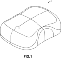
- Fig. 1 is an external perspective view of an exemplary embodiment of a patch pump 1.
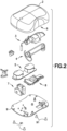
- Fig. 2 is an exploded view of the various components of the patch pump 1 of Fig. 1 .
- the components of the patch pump 1 include a reservoir 4 for storing insulin; a pump 3 for pumping insulin out of the reservoir 4; a power source 5 in the form of one or more batteries; an insertion mechanism 7 for inserting an introducer needle with a catheter into a user's skin; control electronics 8 in the form of a circuit board with optional communications capabilities to outside devices such as a remote controller, computer, or a smart phone; a dose button 6 on the cover 2 for actuating an insulin dose, including a bolus dose; and a base 9 to which various components above may be attached via fasteners 91.
- the patch pump 1 also includes various fluid connector lines that transfer insulin pumped out of the reservoir 4 to the infusion site.
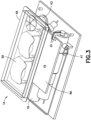
- Fig. 3 is a perspective view of an alternative design for a patch pump 1A having a flexible reservoir 4A, and is illustrated without a cover. Such arrangement may further reduce the external dimensions of the patch pump 1A, with the flexible reservoir 4A filling voids within the patch pump 1A.
- the patch pump 1A is illustrated with a cannula insertion device 7A that inserts the cannula, typically at an acute angle, less than 90 degrees, into the surface of a user's skin.
- the patch pump 1A further comprises a power source 5A in the form of batteries; a metering sub-system 41 that monitors the volume of insulin and includes a low volume detecting ability; control electronics 8A for controlling the components of the device; and a reservoir fill port 43 for receiving a fill syringe 45 to fill the reservoir 4A.
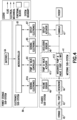
- Fig. 4 is a fluidic architecture and metering sub-system diagram of the patch pump 1A of Fig. 3 .
- the power storage sub-system for the patch pump 1A includes batteries 5A.
- the control electronics 8A of the patch pump 1A may include a microcontroller 81, sensing electronics 81A, pump and valve controller 83, sensing electronics 85 and deployment electronics 87, that control the operation of the patch pump 1A.
- the patch pump 1A includes a fluidics sub-system that comprises a reservoir 4A, a volume sensor 48 for the reservoir 4A, and a reservoir fill port 43 for receiving a fill syringe 45 to fill the reservoir 4A.
- the fluidics sub-system may include a metering system comprising a pump and valve actuator 411 and an integrated pump and valve mechanism 413.
- the fluidics sub-system may further include an occlusion sensor 49, a deploy actuator or cannula insertion device 7, as well as the cannula 47 for insertion into an infusion site on the user's skin.
- the architecture for the patch pump 1 of Figs. 1 and 2 can be the same or similar to that which is illustrated in Fig. 4 .
- Fig. 5 is a perspective view of an exemplary embodiment of the cannula insertion device 7, which can be used as the cannula insertion device for the patch pump 1 and 1A.
- the purpose of the cannula insertion device 7 is to insert a catheter 66 into the skin of a user.
- a hollow introducer needle 70 (illustrated in Fig. 6 ) attached to a needle carriage 10 is slid into the catheter 66 which is attached to a catheter carriage 60.
- Fig. 5 illustrates the device with the metal torsion spring 30 that has been tensioned around a linkage 20 and locked in place by a pin 90 (illustrated in Figs. 19-21 ).
- the tension in the tensioned torsion spring 30 is released to cause the cannula insertion device 7 to be actuated to the insert the introducer needle 70 and the catheter 66 into a user's skin or infusion site and to retract only the introducer needle 70 from the user's skin, such that only the catheter 66 remains in the user's skin.
- the catheter deployment mechanism or cannula insertion device 7 is configured for use in an insulin patch pump, but it is conceivable that the design or variations thereof can be used for any similar purpose in which a needle is inserted and retracted, with or without a catheter.
- the cannula insertion device 7 Upon activation, the cannula insertion device 7 inserts a soft plastic catheter 66 and an introducer needle 70 perpendicularly or substantially perpendicularly to the surface of a user's skin to a preferred depth of about 5.3 mm, and automatically retracts the introducer needle 70, by using an adaptation of a Scotch yoke.
- a button press (not shown) on the patch pump 1 or 1A or an internal electrical actuator (not shown) can initiate the cannula insertion by removing the pin 90.
- the button on the patch pump 1 or 1A can operate mechanically or electrically.
- a remote control device (not shown) can also actuate the cannula insertion device 7.
- the metal torsion spring 30 that powers the Scotch yoke is loaded or rotatively tensioned in the pre-activation state.
- the torsion spring 30 is mounted on the axle post 12 (see Fig. 6 ) of the needle carriage 10.
- a linkage 20 connects the needle carriage 10 to a yoke 54.
- the linkage 20 and yoke 54 converts the rotational motion (approximately 300 degrees) of the metal spring 30 into a vertical descending motion of the needle carriage 10 which in turn pushes on the catheter carriage 60 to push the introducer needle 70 and the catheter 66 into the skin of the user, followed by a vertical ascending of only the needle carriage 10 which withdraws the introducer needle 70 without retracting the catheter 66 from the user's skin.
- the relatively large spring rotation angle (approximately 300 degrees) allows for a smaller linkage 20, which can reduce the overall height of the cannula insertion device 7 that is needed to achieve the required travel distance for the needle carriage 10.
- Such height reduction can permit a patch pump profile to be as low as 12.3 mm. The manner in which this is accomplished will be described in detail below.
- Fig. 6 is a perspective view of a subassembly of the cannula insertion device 7 of Fig. 5 .
- the needle carriage 10 includes a cylindrical axle post 12 that is affixed to and extends outwardly from its main body.
- the linkage 20 includes a main flanged portion 24. Toward one end of the main flanged portion 24 extends a first post 22 with a hole 221 for rotatively receiving the axle post 12 of the needle carriage 10.
- the hole 221 may extend through the main flange portion 24, as illustrated in Fig. 6 .
- Toward another end of the main flanged portion 24 extends, away from the first post 22, a second post 26.
- a mandrel 28 extends from the second post 26.
- the torsion spring 30 is positioned around the first post 22 of the linkage 20, and comprises a straight leg 34 and a bent leg 32.
- the bent leg 32 is attached to the main flanged portion 24 by being inserted into a hole 241 that may extend through the second post 26 and mandrel 28 (as illustrated in Fig. 15 ).
- Fig. 7 is a perspective view of the cannula insertion device 7 of Fig. 5 , illustrated with components of Fig. 6 shown in relation with a base floor 59 on which first and second base uprights 56, 58 and the yoke 54 are attached.
- the needle carriage 10 is illustrated at its uppermost position between the uprights 56, 58 and the straight leg 34 of the tensioned torsion spring 30 that has been wound around the first post 22 of the linkage 20, is abutted to or secured against a notch 52, illustrated in this embodiment as being part of the second base upright 58, and the second post 26 of the linkage 20 is positioned in a first channel 546 of the yoke 54.
- the pin 90 acts as locking mechanism that prevents the release of tension by the metal torsion spring 30, such that when the pin 90 is removed, tension on the torsion spring 30 is released which initiates the movements of the cannula insertion device 7.
- the tension on the tension spring 30 is released, the first post 22 of linkage 20 rotates around the axle post 12 of the needle carriage 10 and the second post 26 of the linkage 20 slides left and right in the first channel 546 of the yoke 54, according to direction "A", and the rotation of the linkage 20 in direction "B", clockwise as is illustrated in Fig. 7 , results in a vertical oscillation of the needle carriage 10 according to direction "C".
- Such movements of the cannula insertion device 7 will further be controlled by other components of the cannula insertion device 7, as described below.
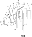
- Fig. 8 is a perspective view of the cannula insertion device 7 of Fig. 5 , illustrated from an opposing view of Fig. 5 , with the needle carriage 10 and the catheter carriage 60 in their uppermost positions (while being positioned between the rails 82, 84, 86, 88), prior to the torsion spring 30 being released.
- the base uprights 56, 58 include metal rails 82, 84, 86, 88 for the needle carriage 10 and catheter carriage 60 to slide on.
- One or more of the rails 82, 84, 86, 88 can also be described as a rail device.
- the catheter carriage 60 includes a main body with a pair of slides 62, 64 that slide on the rails of the base uprights 56, 58, as illustrated in Fig.
- Rails 84 and 86 include resilient metal tabs 841 and 861, respectively, and the tabs 841 and 861 pivot slightly inwardly toward opposing rails, 82 and 88 respectively. In other words, the tabs 841, 861 are bent into the slide track of the catheter carriage 60 formed by the rails 82, 84, 86, 88. The tabs 841 and 861 will restrict the sliding movement of the catheter carriage 60, as described below.
- Fig. 9 is a perspective view of the cannula insertion device 7 of Fig. 8 , illustrated with the needle carriage 10 travelling downward together with the catheter carriage 60, the needle carriage 10 and catheter carriage 60 being nested together as illustrated, shortly after the torsion spring 30 has been released.
- the needle carriage 10 travels downwardly in the carriage slide track formed by the rails 82, 84, 86, 88, according to direction "D"
- the needle carriage 10 slides past the slides 62, 64 of the catheter carriage 60 and presses on the catheter carriage 60, and both the needle carriage 10 and catheter carriage ride in rails 82, 84, 86, 88 in the first and second uprights 56, 58.
- the motion transferred to the needle carriage 10 from the spring 30 and linkage 20 slides the needle carriage 10 downwards along direction "D", and as the needle carriage 10 slides downward, it pushes the catheter carriage 60 downwardly as well.
- the components of the cannula insertion device 7 can be made of various suitable materials, including plastics, metals and polymers that are well-known in the art.
- the rails 82, 84, 86, 88 is preferably metal as noted, but they can alternatively be made of Teflon ® coated plastic or metal to reduce frictional resistance against the needle carriage 10 and the catheter carriage 60 sliding thereon.
- Fig. 10 is a perspective view of the cannula insertion device 7 of Fig. 9 , similar to that of Fig. 9 but illustrated without the needle carriage 10 for clarity.
- the resilient tabs 841, 861 bend out of the way, permitting both the needle carriage 10 and the catheter carriage 60 to slide downward, along the rails 82, 84, 86, 88, without being hindered by the presence of the resilient tabs 841, 861, as illustrated in Figs. 10 and 11 .
- Fig. 10 is a perspective view of the cannula insertion device 7 of Fig. 9 , similar to that of Fig. 9 but illustrated without the needle carriage 10 for clarity.
- the upper end of the introducer needle 70 is connected to a connector 16 of the flexible fluid line 14 and is in fluid communication with a reservoir and pump (not shown) so that the introducer needle 70 can deliver insulin to the infusion site.
- the introducer needle 70 is typically a hypodermic needle, a hollow metal tube with a sharp end 71 at an open end thereof.
- Fig. 11 is a perspective view of the insertion device of Fig. 10 , illustrated with the needle carriage 10 and the catheter carriage 60 resting on the base floor 59, with the introducer needle 70 and catheter 66 fully extending through the exit hole 591 (as illustrated in Fig. 10 ) of the base floor 59.
- the slides 62, 64 of the catheter carriage 60 are positioned below the resilient tabs 841, 861 of the rails 84, 86 and in this position, the resilient tabs 841, 861 have returned to their bent positions (as in Fig. 8 ) in which the resilient tabs 841, 861 extend or pivot toward opposing rails.
- FIG. 11 illustrates the introducer needle 70 positioned through the catheter 66, that is fully inserted into a user's skin (not shown), along with the catheter 66.
- Fig. 12 is a perspective view of the cannula insertion device 7 of Fig. 11 , illustrated with the needle carriage 10 returning to its uppermost position (as in Fig. 8 ) to retract the introducer needle 70 back through the exit hole 591 of the base floor 59, while the catheter carriage 60 remains locked at or near the base floor 59 of the base 50 by the resilient tabs 861, 841 swinging back or returning to their original form, which prevents the catheter carriage 60 from being retracted upward in the direction of "E".
- Fig. 12 illustrates the upward movement of the needle carriage 10, to extract the introducer needle 70 from the user's skin while the catheter 66 remains lodged into the user's skin.
- Fig. 12 A is a cross-sectional view of the catheter carriage 60, illustrating the sharp end 71 of the introducer needle 70 penetrating a septum 68, so that insulin pumped out of the sharp end 71 of the introducer needle 70, via the fluid line 14 and connector 16, is in fluid communication with the infusion site via the catheter 66 without leakage.
- the septum 68 prevents backflow of insulin via the catheter 66 from the infusion site.
- the cannula insertion device 7, illustrated in Figs. 5-12 is that it can be smaller than existing devices, which can allow for a smaller overall patch pump.
- Another advantage of the cannula insertion device 7 is that the insertion of the introducer needle 70 can be perpendicular or substantially perpendicular to the surface of the user's skin, which allows a shorter insertion wound and a reduction in scar tissue in comparison with other devices that insert a cannula (metal cannula or plastic catheter) at an acute angle from the surface of the skin.
- Yet another advantage is that the insertion of both the introducer needle 70 and the catheter 66 into a user's skin and the retraction of the introducer needle 70 are accomplished by using a single spring device, which can reduce the overall number of parts, complexity and cost.
- An important aspect when developing an insulin patch pump is its overall size. In other words, the smaller the footprint and the lower the profile of the patch pump, it is more likely that a user would be willing to wear it. Hence it is important to minimize the size of the patch pump. In order to do so, it is necessary to reduce one or more components of the path pump.
- a patch pump that incorporates the cannula insertion device 7 can be reduced in its overall size and footprint.
- the linkage 20 and yoke 54 can be further reduced in size.
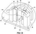
- FIG. 13 is perspective view of a sub-assembly of the cannula insertion device 7 of Fig. 5 , illustrating a base floor 59 with a through-hole 591, rails 82, 84, 86, 88 connected to base uprights 56, 58, and a yoke 54.
- a base floor 59 with a through-hole 591, rails 82, 84, 86, 88 connected to base uprights 56, 58, and a yoke 54.
- One or more of the components above can be made separately and assembled to form the base 50 or integrally molded together for ease of manufacture.
- the cannula insertion device 7 would still be functional.
- a single base upright 56 can be used with its rails 82, 84.
- the yoke 54 is illustrated as being spaced apart from base uprights 56, 58, but it is conceivable that they are integrally formed together.
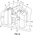
- Fig. 14 is perspective view of the sub-assembly of Fig. 13 , illustrated with the first slide 62 of the catheter carriage 60 being positioned between the rails 82, 84 of the first base upright 56 and the second slide 64 of the catheter carriage 60 being positioned between the rails 86, 88 of the second base uprights 58.
- the catheter carriage 60 is at its highest position between the rails 82, 84, 86, 88.
- the catheter 66 is attached to the catheter carriage and is guided in or above the exit hole 591 of the base floor 59. In this position, the slides 62, 68 of the catheter carriage 60 are positioned above the resilient tabs 841 and 861 of the rails 84 and 86.
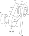
- Fig. 15 is a perspective view of the sub-assembly of linkage 20 and the torsion spring 30 of the cannula insertion device 7 of Fig. 5 .
- the spring 30 is illustrated as being assembled around the first post 22 of the linkage 20, with a bent leg 32 of the spring 20 being inserted into the hole 241 at one side of the main flanged portion 24 of the linkage 20, and the other end of the spring 30 being a straight leg 34.
- a through-hole 243 extends through the main flanged portion 24 of the linkage 20 for receiving the pin 90 (illustrated in Figs. 19-21 ).
- the post 22 includes a hole 221 for receiving the axle post 12 of the needle carriage 10.
- a second post 26 extends outwardly from another side of the main flanged portion 24 and distant from the first post 22.
- a mandrel 28 having a larger diameter than the post 26 extends from the post 26.
- Fig. 16 is a front view of a sub-assembly of the cannula insertion device 7 of Fig. 14 , illustrated with the mandrel 28 of the linkage 20 being inserted into a large opening 542 of the yoke 54, the large opening 542 having a diameter slightly larger than that of the mandrel 28 for receiving the mandrel 28 therethrough.
- the second post 26 of the linkage 20 is slidable into both the elongated slots 546,548 of the yoke 54, while the mandrel 28 is only slidable through the large opening 542.
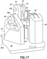
- Fig. 17 is a perspective view of a sub-assembly of the cannula insertion device 7 of Fig. 16 , illustrated with the second post 26 moved along the second elongated slot 548 to the uppermost position thereof. Hence, the mandrel 28 of the linkage 20 is also positioned at its uppermost position.
- the catheter carriage 60 is illustrated in Fig. 17 with its slides 62, 64 at their uppermost positions between the rails 82, 84, 86, 88 of the base uprights 56, 58.
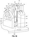
- Fig. 18 is a perspective view of a sub-assembly of the cannula insertion device 7 of Fig.17 , illustrated with the axle post 12 of the needle carriage 10 received in the hole 221 of the linkage 20, the introducer needle 70 of the needle carriage 10 positioned above the catheter 66 of the catheter carriage 60 that has been slid downwards along the rails 82, 84, 86, 88.
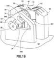
- Fig. 19 is a perspective view of a sub-assembly of the cannula insertion device 7 of Fig.18 .
- the needle carriage 10 is slid onto the rails 82, 84, 86, 88, which pushes the second post 26 downwards along the second elongated slot 548, past the large opening 542 and into the first elongated slot 546 until hole 243 of the linkage and hole 549 of the yoke 54 align.
- the pin 90 is then placed into the aligned holes 243, 549 to lock the linkage 20 to the other components of the cannula insertion device 7.
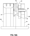
- Fig. 19A is a partial cutout view that illustrates with the needle 90 that is inserted into the yoke and linkage to lock the tensioned spring 30, prior to activation.
- Fig. 20 is a perspective view of the cannula insertion device 7 of Fig. 20 , illustrated with the free leg 34 of the torsion spring 30 being rotated around the axle post 12 of the needle carriage 10, shown in the clockwise direction "F" to tension the torsion spring 30 to store potential energy.
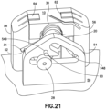
- Fig. 21 is a perspective view of the cannula insertion device 7 of Fig. 19 , illustrated with the straight leg 34 of the tensioned torsion spring 30 abutting against a notch 52 on the second base upright 58 and the cannula insertion device 7 is now prepared or loaded for activation.
- a release button (not shown) on the patch pump 1, 1A
- the pin 90 is pulled out of the hole 243 of the linkage 20, which causes the release of the tensioned torsion spring 30, causing the stored potential energy in the tensioned torsion spring 30 to be translated into linear motions of the needle carriage 10 and catheter carriage 60, via the Scotch-yoke mechanism, as described above.
- the pin 90 is in mechanical connection with the release button on the patch pump 1, 1A such that upon actuation of the release button by a user, the pin 90 is retracted from the linkage 20, to release the tension on the torsion spring 30 to activate the cannula insertion device 7 and thereby insert the introducer needle 70 and catheter 66 into the insertion site and then retract only the introducer needle 70, as described above.
- an electrical actuator can be used to withdraw the pin 90 from the linkage 20 in response to the user's operation of an electrical switch, electrical push button or other type of electrical input device located on the body of the patch pump 1, 1A or on a remote control device.
- the device could be locked and released by an obstruction under the needle carriage 10 or catheter carriage 60 instead of the pull pin 90.
- the pull pin 90 which acts as a locking device as the torsion spring 30 is wound, and as an activation device when the pull pin 90 is then removed.
- the locking device and the activation device can be separate units.
- orientational descriptors are intended to facilitate the description of the exemplary embodiments of the present invention, and are intended to limit the structure of the exemplary embodiments of the present invention to any particular position or orientation.
Landscapes
- Health & Medical Sciences (AREA)
- Vascular Medicine (AREA)
- Engineering & Computer Science (AREA)
- Anesthesiology (AREA)
- Biomedical Technology (AREA)
- Heart & Thoracic Surgery (AREA)
- Hematology (AREA)
- Life Sciences & Earth Sciences (AREA)
- Animal Behavior & Ethology (AREA)
- General Health & Medical Sciences (AREA)
- Public Health (AREA)
- Veterinary Medicine (AREA)
- Dermatology (AREA)
- Infusion, Injection, And Reservoir Apparatuses (AREA)
Claims (9)
- Patch-Pumpe mit:einem Reservoir (4);einer Pumpe (3);einer Kanüleneinführvorrichtung (7);einem Nadelschlitten (10);einem Katheterschlitten (60);einer Schienenvorrichtung (82, 84, 86, 88), auf welcher der Nadelschlitten (10) und/oder der Katheterschlitten (60) gleitend verschiebbar ist;wobei die Kanüleneinführvorrichtung (7) einen von einer Torsionsfeder (30) angetriebenen Kurbeltrieb (54) zum Einführen einer Einführnadel (70) und eines Katheters (70) in eine Infusionsstelle und zum Zurückziehen nur der Einführnadel (70) aufweist, wobei der Katheter (66) in die Infusionsstelle eingeführt verbleibt;wobei die Torsionsfeder (30) an einem Achsschenkel (12) des Nadelschlittens (10) angebracht ist;wobei ein Gestänge (20) den Nadelschlitten (10) mit dem Kurbeltrieb (54) verbindet;wobei der Kurbeltrieb die Drehbewegung der Torsionsfeder (30) in eine lineare Abwärtsbewegung des Nadelschlittens (10) umwandelt, welcher seinerseits gegen den Katheterschlitten (60) drückt, um die Einführnadel (70) und den Katheter (66) zu schieben, wodurch die Einführnadel (70) und der Katheter (66) in die Einführstelle eingeführt werden, gefolgt von einer linearen Aufwärtsbewegung nur des Nadelschlittens (10), welche nur die Einführnadel (70) zurückzieht, ohne den Katheter (66) zurückzuziehen;wobei die Schienenvorrichtung (82, 84, 86, 88) einen gebogenen elastischen Verriegelungsansatz (841, 861) aufweist, der nachgibt, wenn der Katheterschlitten (60) unter den elastischen Ansatz (841, 861) gleitet, und sich, nachdem der Katheterschlitten (60) an dem elastischen Ansatz (841, 861) vorbei geglitten ist, zurückstellt, um ein Gleiten des Katheterschlittens (60) über den elastischen Ansatz (841, 861) hinaus zu verhindern; undwobei Infusionslösung aus dem Reservoir (4) von der Pumpe (3) in die Infusionsstelle gepumpt wird, nachdem der Katheter (66) in die Infusionsstelle eingeführt wurde.
- Patch-Pumpe nach Anspruch 1, bei welcher die Einführnadel und der Katheter im Wesentlichen senkrecht zu der Infusionsstelle eingeführt werden.
- Patch-Pumpe nach Anspruch 1, ferner mit einem Schalter zum Betätigen des Einführens des Katheters in die Infusionsstelle.
- Patch-Pumpe nach Anspruch 1, ferner mit einem Dosiersystem zum Dosieren der Menge der Infusionslösung, welche von der Pumpe aus dem Reservoir gepumpt wird.
- Patch-Pumpe nach Anspruch 4, ferner mit einer Steuerung zum Stern der Abgabe gewählter Infusionslösungsdosen in die Infusionsstelle.
- Patch-Pumpe nach Anspruch 1, ferner mit einer Stromquelle zum Bestromen der Pumpe und/oder des Dosiersystems und/oder der Steuerung.
- Patch-Pumpe nach Anspruch 1, ferner mit einer Abdeckung zum Aufnehmen der Kanüleneinführvorrichtung, des Reservoirs, der Pumpe, des Dosiersystems und der Steuerung.
- Patch-Pumpe nach Anspruch 1, ferner mit einer Austrittsöffnung, durch welche die Einführnadel und der Katheter in die Infusionsstelle eingeführt werden und durch welche die Einführnadel nach dem Einführen des Katheters in die Infusionsstelle zurückgezogen wird.
- Patch-Pumpe nach einem der Ansprüche 1-8, bei welcher die Einführnadel hohl ist und geeignet ist, die Infusionslösung dem Katheter zuzuführen.
Applications Claiming Priority (3)
| Application Number | Priority Date | Filing Date | Title |
|---|---|---|---|
| US14/261,386 US10195342B2 (en) | 2014-04-24 | 2014-04-24 | Cannula deployment mechanism |
| PCT/US2015/027358 WO2015164645A1 (en) | 2014-04-24 | 2015-04-23 | Cannula deployment mechanism |
| EP15782482.2A EP3134155B1 (de) | 2014-04-24 | 2015-04-23 | Ausfahrmechanismus für kanüle |
Related Parent Applications (2)
| Application Number | Title | Priority Date | Filing Date |
|---|---|---|---|
| EP15782482.2A Division-Into EP3134155B1 (de) | 2014-04-24 | 2015-04-23 | Ausfahrmechanismus für kanüle |
| EP15782482.2A Division EP3134155B1 (de) | 2014-04-24 | 2015-04-23 | Ausfahrmechanismus für kanüle |
Publications (3)
| Publication Number | Publication Date |
|---|---|
| EP3766533A1 EP3766533A1 (de) | 2021-01-20 |
| EP3766533B1 true EP3766533B1 (de) | 2024-08-07 |
| EP3766533C0 EP3766533C0 (de) | 2024-08-07 |
Family
ID=54333208
Family Applications (2)
| Application Number | Title | Priority Date | Filing Date |
|---|---|---|---|
| EP20194170.5A Active EP3766533B1 (de) | 2014-04-24 | 2015-04-23 | Ausfahrmechanismus für kanüle |
| EP15782482.2A Active EP3134155B1 (de) | 2014-04-24 | 2015-04-23 | Ausfahrmechanismus für kanüle |
Family Applications After (1)
| Application Number | Title | Priority Date | Filing Date |
|---|---|---|---|
| EP15782482.2A Active EP3134155B1 (de) | 2014-04-24 | 2015-04-23 | Ausfahrmechanismus für kanüle |
Country Status (7)
| Country | Link |
|---|---|
| US (4) | US10195342B2 (de) |
| EP (2) | EP3766533B1 (de) |
| JP (1) | JP6553642B2 (de) |
| CN (1) | CN206822918U (de) |
| CA (2) | CA2944799C (de) |
| ES (1) | ES2851774T3 (de) |
| WO (1) | WO2015164645A1 (de) |
Families Citing this family (81)
| Publication number | Priority date | Publication date | Assignee | Title |
|---|---|---|---|---|
| PT1762259E (pt) | 2005-09-12 | 2010-12-10 | Unomedical As | Insersor para um conjunto de infusão com uma primeira e uma segunda unidades de mola |
| CA2792138A1 (en) | 2010-03-30 | 2011-10-06 | Unomedical A/S | Medical device |
| WO2012123274A1 (en) | 2011-03-14 | 2012-09-20 | Unomedical A/S | Inserter system with transport protection |
| US11197689B2 (en) | 2011-10-05 | 2021-12-14 | Unomedical A/S | Inserter for simultaneous insertion of multiple transcutaneous parts |
| EP2583715A1 (de) | 2011-10-19 | 2013-04-24 | Unomedical A/S | Infusionsschlauchsystem und Herstellungsverfahren |
| EP2832390A1 (de) * | 2013-07-30 | 2015-02-04 | Sensile Pat AG | Arzneimittelabgabevorrichtung mit Nadelbetätigungsmechanismus |
| WO2015032743A1 (en) * | 2013-09-05 | 2015-03-12 | Sanofi-Aventis Deutschland Gmbh | Drive mechanism for a needle insertion arrangement |
| CN106488782B (zh) | 2014-06-03 | 2021-03-09 | 安姆根有限公司 | 用于辅助药物递送装置的用户的装置和方法 |
| JP2017538512A (ja) | 2014-12-19 | 2017-12-28 | アムジエン・インコーポレーテツド | ライブボタンまたはユーザインタフェースフィールドを含む薬物送達装置 |
| US10799630B2 (en) | 2014-12-19 | 2020-10-13 | Amgen Inc. | Drug delivery device with proximity sensor |
| US10625018B2 (en) * | 2015-02-10 | 2020-04-21 | Amgen Inc. | Rotationally biased insertion mechanism for a drug delivery pump |
| EA036104B1 (ru) | 2015-03-09 | 2020-09-29 | Эмджен Инк. | Приводные механизмы для помп подачи лекарства |
| EP3268078B1 (de) | 2015-03-10 | 2020-11-04 | Regeneron Pharmaceuticals, Inc. | Aseptisches durchstechsystem |
| USD794770S1 (en) * | 2015-06-26 | 2017-08-15 | Unitract Syringe Pty Ltd | Drug delivery pump |
| USD794771S1 (en) | 2015-07-10 | 2017-08-15 | Unitract Syringe Pty Ltd. | Drug delivery pump |
| US10576207B2 (en) | 2015-10-09 | 2020-03-03 | West Pharma. Services IL, Ltd. | Angled syringe patch injector |
| USD776253S1 (en) * | 2015-11-18 | 2017-01-10 | Medtrum Technologies Inc. | Disposable tubeless insulin pump |
| USD801346S1 (en) * | 2015-12-04 | 2017-10-31 | Hand Held Products, Inc. | Wearable module |
| WO2017125817A1 (en) | 2016-01-19 | 2017-07-27 | Unomedical A/S | Cannula and infusion devices |
| CN113041432B (zh) | 2016-01-21 | 2023-04-07 | 西医药服务以色列有限公司 | 包括视觉指示物的药剂输送装置 |
| USD805631S1 (en) * | 2016-01-21 | 2017-12-19 | Becton, Dickinson And Company | Drug delivery device with insertion mechanism button safety |
| AU366963S (en) * | 2016-01-21 | 2016-02-09 | Cpie Pharmacy Services R & D Pty Ltd | Infusion pump |
| USD829889S1 (en) * | 2016-01-21 | 2018-10-02 | Becton, Dickinson And Company | Wearable drug delivery device with adhesive |
| USD806232S1 (en) * | 2016-01-21 | 2017-12-26 | Becton, Dickinson And Company | Drug delivery device with insertion mechanism |
| USD857191S1 (en) | 2016-01-21 | 2019-08-20 | Becton, Dickinson And Company | Wearable drug delivery device |
| USD830537S1 (en) * | 2016-01-21 | 2018-10-09 | Becton, Dickinson And Company | Wearable drug delivery device with adhesive and liner |
| USD835261S1 (en) * | 2016-01-22 | 2018-12-04 | ViCentra, B.V. | Pump and cartridge set for portable patient infusion system |
| USD826396S1 (en) | 2016-02-10 | 2018-08-21 | Amgen Inc. | On-body injector for drug delivery |
| USD822197S1 (en) | 2016-02-10 | 2018-07-03 | Amgen Inc. | On-body injector for drug delivery |
| USD821571S1 (en) * | 2016-02-10 | 2018-06-26 | Amgen Inc. | On-body injector for drug delivery |
| TWI746569B (zh) | 2016-06-08 | 2021-11-21 | 瑞士商瑞健醫療股份有限公司 | 計量器具、注射裝置、及其應用 |
| USD813380S1 (en) | 2016-08-05 | 2018-03-20 | Amgen Inc. | On-body injector |
| USD838359S1 (en) * | 2016-09-21 | 2019-01-15 | Amgen Inc. | On-body injector |
| USD878556S1 (en) | 2016-10-26 | 2020-03-17 | West Pharmaceutical Services, Inc. | Injector device |
| USD806863S1 (en) * | 2016-10-26 | 2018-01-02 | West Pharmaceutical Services, Inc. | Injector device |
| USD805632S1 (en) * | 2016-10-26 | 2017-12-19 | West Pharmaceutical Services, Inc. | Injector device |
| USD878555S1 (en) | 2016-10-26 | 2020-03-17 | West Pharmaceutical Services, Inc. | Injector device |
| USD882765S1 (en) | 2016-10-26 | 2020-04-28 | West Pharmaceutical Services, Inc. | Injector device |
| USD806234S1 (en) * | 2016-10-26 | 2017-12-26 | West Pharmaceutical Services, Inc. | Injector device |
| USD807499S1 (en) * | 2016-10-26 | 2018-01-09 | West Pharmaceutical Services, Inc. | Injector device |
| USD878557S1 (en) | 2016-10-26 | 2020-03-17 | West Pharmaceutical Services, Inc. | Injector device |
| USD806235S1 (en) * | 2016-10-26 | 2017-12-26 | West Pharmaceutical Services, Inc. | Injector device |
| USD805633S1 (en) * | 2016-10-26 | 2017-12-19 | West Pharmaceutical Services, Inc. | Injector device |
| USD808011S1 (en) * | 2016-10-26 | 2018-01-16 | West Pharmaceutical Services, Inc. | Injector device |
| ES2985905T3 (es) | 2016-11-22 | 2024-11-07 | Lts Device Tech Ltd | Aparato para suministrar una sustancia terapéutica |
| WO2018096149A1 (de) | 2016-11-28 | 2018-05-31 | Idorsia Pharmaceuticals Ltd | Vorrichtung zur abgabe einer substanz |
| USD839416S1 (en) * | 2016-12-15 | 2019-01-29 | Novartis Ag | Auto-injector |
| USD812739S1 (en) * | 2017-02-24 | 2018-03-13 | Abbvie Inc. | Wearable injector device |
| USD812738S1 (en) * | 2017-02-24 | 2018-03-13 | Abbvie Inc. | Wearable injector device |
| IL268386B2 (en) * | 2017-03-09 | 2023-11-01 | Amgen Inc | Insertion mechanism for a drug delivery device |
| EA201992189A1 (ru) | 2017-05-05 | 2020-03-06 | Ридженерон Фармасьютикалз, Инк. | Автоматический медицинский шприц |
| CN111093735B (zh) | 2017-07-07 | 2021-04-27 | 纽罗德姆有限公司 | 用于流体药物的皮下输送的设备 |
| US20230123806A1 (en) | 2017-07-07 | 2023-04-20 | Neuroderm, Ltd. | Device for subcutaneous delivery of fluid medicament |
| WO2019014014A1 (en) * | 2017-07-14 | 2019-01-17 | Amgen Inc. | NEEDLE INSERTION-RETRACTING SYSTEM HAVING DOUBLE TORSION SPRING SYSTEM |
| US11471593B2 (en) * | 2018-03-08 | 2022-10-18 | Flex Ltd. | Angled integrated soft cannula |
| US11554213B2 (en) * | 2018-09-22 | 2023-01-17 | Shl Medical Ag | Injector needle insertion retraction assembly |
| ES2986346T3 (es) | 2018-10-05 | 2024-11-11 | Lts Device Tech Ltd | Secuencia de activación |
| CA3126999A1 (en) | 2019-02-22 | 2020-08-27 | Deka Products Limited Partnership | Infusion set and inserter assembly systems and methods |
| FR3093437B1 (fr) | 2019-03-07 | 2024-05-24 | Nemera La Verpilliere | Dispositif d’insertion d’une aiguille pour la distribution d’un produit dans un site |
| BR112021023304A2 (pt) | 2019-05-20 | 2022-02-01 | Unomedical As | Dispositivo de infusão rotativo e métodos do mesmo |
| WO2020255105A1 (en) * | 2019-06-21 | 2020-12-24 | Preci Health Sa | Medical injection system and method |
| EP4003459A4 (de) * | 2019-07-24 | 2023-08-30 | Enable Injections, Inc. | Vorrichtungen und verfahren zur injektion und übertragung von medizinischen flüssigkeiten |
| USD950713S1 (en) * | 2019-10-31 | 2022-05-03 | Eoflow Co., Ltd. | Medicine injector |
| FR3103388B1 (fr) | 2019-11-26 | 2021-10-29 | Nemera La Verpilliere | Dispositif d’injection d’un produit |
| FR3109888B1 (fr) | 2020-05-07 | 2022-04-15 | Nemera La Verpilliere | Dispositif d’insertion d’une aiguille pour la distribution d’un produit dans un site |
| FR3112961B1 (fr) | 2020-07-28 | 2022-12-02 | Nemera La Verpilliere | Dispositif d’insertion d’une aiguille pour la distribution d’un produit dans un site |
| CN112156281B (zh) * | 2020-10-12 | 2022-02-11 | 普昂(杭州)医疗科技股份有限公司 | 一种锁针结构、针管长度调节方法及针装置 |
| FR3115211B1 (fr) | 2020-10-15 | 2022-10-07 | Nemera La Verpilliere | Dispositif d’insertion d’une aiguille pour la distribution d’un produit dans un site |
| US12447269B2 (en) * | 2020-11-11 | 2025-10-21 | Medtronic Minimed, Inc. | Torsional insertion devices |
| US11951281B2 (en) | 2020-11-11 | 2024-04-09 | Medtronic Minimed, Inc. | Fluid conduit insertion devices |
| US11806505B2 (en) | 2020-12-02 | 2023-11-07 | Medtronic Minimed, Inc. | Single-site insertion of multiple medical devices |
| US11738140B2 (en) | 2021-01-15 | 2023-08-29 | Medtronic Minimed, Inc. | Insertion device with linkage assembly |
| US11944786B2 (en) | 2021-01-18 | 2024-04-02 | Medtronic Minimed, Inc. | Infusion device |
| US11607505B1 (en) | 2021-02-19 | 2023-03-21 | Fresenius Kabi Deutschland Gmbh | Wearable injector with sterility sensors |
| US11426523B1 (en) | 2021-02-19 | 2022-08-30 | Fresenius Kabi Deutschland Gmbh | Drug delivery assembly including a removable cartridge |
| US11633537B1 (en) | 2021-02-19 | 2023-04-25 | Fresenius Kabi Deutschland Gmbh | Drug delivery assembly including a pre-filled cartridge |
| US11419976B1 (en) | 2021-04-30 | 2022-08-23 | Fresenius Kabi Deutschland Gmbh | Wearable drug delivery device with pressurized fluid dispensing |
| US11504470B1 (en) | 2021-04-30 | 2022-11-22 | Fresenius Kabi Deutschland Gmbh | Deformable drug reservoir for wearable drug delivery device |
| USD1007676S1 (en) | 2021-11-16 | 2023-12-12 | Regeneron Pharmaceuticals, Inc. | Wearable autoinjector |
| EP4461330A4 (de) * | 2022-01-04 | 2025-04-16 | Eoflow Co., Ltd. | Nadelanordnung und flüssigmedikamentinjektionsvorrichtung damit |
| EP4637554A1 (de) * | 2022-12-21 | 2025-10-29 | Insulet Corporation | Eingrenzung, aktivierung, entfaltung und integrierte funktionen von flexiblen, schlanken elementen |
Family Cites Families (21)
| Publication number | Priority date | Publication date | Assignee | Title |
|---|---|---|---|---|
| US6607509B2 (en) | 1997-12-31 | 2003-08-19 | Medtronic Minimed, Inc. | Insertion device for an insertion set and method of using the same |
| AU2001288575B2 (en) | 2000-09-08 | 2006-06-01 | Insulet Corporation | Devices, systems and methods for patient infusion |
| US6830562B2 (en) | 2001-09-27 | 2004-12-14 | Unomedical A/S | Injector device for placing a subcutaneous infusion set |
| US6960192B1 (en) * | 2002-04-23 | 2005-11-01 | Insulet Corporation | Transcutaneous fluid delivery system |
| US20040010207A1 (en) | 2002-07-15 | 2004-01-15 | Flaherty J. Christopher | Self-contained, automatic transcutaneous physiologic sensing system |
| ES2293273T3 (es) | 2003-06-12 | 2008-03-16 | Disetronic Licensing Ag | Dispositivo de insercion para equipos de infusion. |
| ES2683845T3 (es) * | 2003-08-12 | 2018-09-28 | Becton, Dickinson And Company | Dispositivo de infusión a modo de parche con miembro de protección |
| US8167841B2 (en) * | 2005-01-24 | 2012-05-01 | Novo Nordisk A/S | Transcutaneous device assembly |
| MX343851B (es) | 2006-02-09 | 2016-11-24 | Deka Products Ltd Partnership * | Sistemas y métodos de suministro de fluido de bombeo que usan un montaje de aplicación de fuerza. |
| US20070282269A1 (en) | 2006-05-31 | 2007-12-06 | Seattle Medical Technologies | Cannula delivery apparatus and method for a disposable infusion device |
| US7771412B2 (en) | 2006-10-18 | 2010-08-10 | Insulet Corporation | Environmental seal for fluid delivery device |
| JP5277242B2 (ja) * | 2007-04-30 | 2013-08-28 | メドトロニック ミニメド インコーポレイテッド | 注入媒質送達システム用の針挿入および流体流通接続 |
| US8002752B2 (en) | 2007-06-25 | 2011-08-23 | Medingo, Ltd. | Protector apparatus |
| TWI394765B (zh) | 2008-12-12 | 2013-05-01 | Ind Tech Res Inst | 難燃水性聚胺基甲酸酯分散液 |
| US10092691B2 (en) | 2009-09-02 | 2018-10-09 | Becton, Dickinson And Company | Flexible and conformal patch pump |
| ATE553800T1 (de) | 2009-11-26 | 2012-05-15 | Hoffmann La Roche | Extern auslösbare kanülenanordnung |
| US8905972B2 (en) | 2010-11-20 | 2014-12-09 | Perqflo, Llc | Infusion pumps |
| US9522229B2 (en) | 2011-02-09 | 2016-12-20 | Becton, Dickinson And Company | Infusion device with automatic insertion and introducer needle retraction |
| CN203898932U (zh) | 2011-02-09 | 2014-10-29 | 贝克顿·迪金森公司 | 皮下注入器械 |
| US9463280B2 (en) * | 2012-03-26 | 2016-10-11 | Medimop Medical Projects Ltd. | Motion activated septum puncturing drug delivery device |
| WO2014049886A1 (ja) | 2012-09-28 | 2014-04-03 | テルモ株式会社 | 穿刺装置及び薬液投与装置 |
-
2014
- 2014-04-24 US US14/261,386 patent/US10195342B2/en active Active
-
2015
- 2015-04-23 WO PCT/US2015/027358 patent/WO2015164645A1/en not_active Ceased
- 2015-04-23 JP JP2016563978A patent/JP6553642B2/ja active Active
- 2015-04-23 EP EP20194170.5A patent/EP3766533B1/de active Active
- 2015-04-23 CA CA2944799A patent/CA2944799C/en active Active
- 2015-04-23 CN CN201590000456.6U patent/CN206822918U/zh not_active Expired - Lifetime
- 2015-04-23 ES ES15782482T patent/ES2851774T3/es active Active
- 2015-04-23 CA CA3106718A patent/CA3106718C/en active Active
- 2015-04-23 EP EP15782482.2A patent/EP3134155B1/de active Active
-
2018
- 2018-11-20 US US16/196,536 patent/US10722646B2/en active Active
- 2018-12-21 US US16/229,166 patent/US10987467B2/en active Active
-
2021
- 2021-03-29 US US17/216,117 patent/US11904135B2/en active Active
Also Published As
| Publication number | Publication date |
|---|---|
| ES2851774T3 (es) | 2021-09-08 |
| EP3134155A1 (de) | 2017-03-01 |
| US20210213194A1 (en) | 2021-07-15 |
| CA2944799C (en) | 2021-03-09 |
| EP3134155B1 (de) | 2020-11-25 |
| US11904135B2 (en) | 2024-02-20 |
| CA2944799A1 (en) | 2015-10-29 |
| JP6553642B2 (ja) | 2019-07-31 |
| US10987467B2 (en) | 2021-04-27 |
| US10195342B2 (en) | 2019-02-05 |
| CA3106718C (en) | 2023-12-19 |
| US20150306307A1 (en) | 2015-10-29 |
| US20190117885A1 (en) | 2019-04-25 |
| JP2017517296A (ja) | 2017-06-29 |
| CN206822918U (zh) | 2018-01-02 |
| EP3766533A1 (de) | 2021-01-20 |
| EP3134155A4 (de) | 2017-11-15 |
| US20190083704A1 (en) | 2019-03-21 |
| CA3106718A1 (en) | 2015-10-29 |
| WO2015164645A1 (en) | 2015-10-29 |
| EP3766533C0 (de) | 2024-08-07 |
| US10722646B2 (en) | 2020-07-28 |
Similar Documents
| Publication | Publication Date | Title |
|---|---|---|
| US11904135B2 (en) | Cannula deployment mechanism | |
| US12458779B2 (en) | Catheter insertion mechanism for a patch pump | |
| US10265466B2 (en) | Fluid infusion device | |
| JP6960981B2 (ja) | カテーテル挿入デバイス | |
| US20240269433A1 (en) | Catheter insertion device and method of inserting a catheter | |
| EP4661939A2 (de) | Kathetereinführvorrichtung und verfahren zum einführen eines katheters |
Legal Events
| Date | Code | Title | Description |
|---|---|---|---|
| PUAI | Public reference made under article 153(3) epc to a published international application that has entered the european phase |
Free format text: ORIGINAL CODE: 0009012 |
|
| STAA | Information on the status of an ep patent application or granted ep patent |
Free format text: STATUS: THE APPLICATION HAS BEEN PUBLISHED |
|
| AC | Divisional application: reference to earlier application |
Ref document number: 3134155 Country of ref document: EP Kind code of ref document: P |
|
| AK | Designated contracting states |
Kind code of ref document: A1 Designated state(s): AL AT BE BG CH CY CZ DE DK EE ES FI FR GB GR HR HU IE IS IT LI LT LU LV MC MK MT NL NO PL PT RO RS SE SI SK SM TR |
|
| STAA | Information on the status of an ep patent application or granted ep patent |
Free format text: STATUS: REQUEST FOR EXAMINATION WAS MADE |
|
| 17P | Request for examination filed |
Effective date: 20210211 |
|
| RBV | Designated contracting states (corrected) |
Designated state(s): AL AT BE BG CH CY CZ DE DK EE ES FI FR GB GR HR HU IE IS IT LI LT LU LV MC MK MT NL NO PL PT RO RS SE SI SK SM TR |
|
| STAA | Information on the status of an ep patent application or granted ep patent |
Free format text: STATUS: EXAMINATION IS IN PROGRESS |
|
| 17Q | First examination report despatched |
Effective date: 20220609 |
|
| GRAP | Despatch of communication of intention to grant a patent |
Free format text: ORIGINAL CODE: EPIDOSNIGR1 |
|
| STAA | Information on the status of an ep patent application or granted ep patent |
Free format text: STATUS: GRANT OF PATENT IS INTENDED |
|
| RIN1 | Information on inventor provided before grant (corrected) |
Inventor name: JACKSON, ALYSSA Inventor name: COLE, RUSSEL |
|
| INTG | Intention to grant announced |
Effective date: 20240318 |
|
| GRAS | Grant fee paid |
Free format text: ORIGINAL CODE: EPIDOSNIGR3 |
|
| GRAA | (expected) grant |
Free format text: ORIGINAL CODE: 0009210 |
|
| STAA | Information on the status of an ep patent application or granted ep patent |
Free format text: STATUS: THE PATENT HAS BEEN GRANTED |
|
| AC | Divisional application: reference to earlier application |
Ref document number: 3134155 Country of ref document: EP Kind code of ref document: P |
|
| AK | Designated contracting states |
Kind code of ref document: B1 Designated state(s): AL AT BE BG CH CY CZ DE DK EE ES FI FR GB GR HR HU IE IS IT LI LT LU LV MC MK MT NL NO PL PT RO RS SE SI SK SM TR |
|
| REG | Reference to a national code |
Ref country code: GB Ref legal event code: FG4D |
|
| REG | Reference to a national code |
Ref country code: CH Ref legal event code: EP |
|
| REG | Reference to a national code |
Ref country code: IE Ref legal event code: FG4D |
|
| REG | Reference to a national code |
Ref country code: DE Ref legal event code: R096 Ref document number: 602015089501 Country of ref document: DE |
|
| U01 | Request for unitary effect filed |
Effective date: 20240909 |
|
| U07 | Unitary effect registered |
Designated state(s): AT BE BG DE DK EE FI FR IT LT LU LV MT NL PT RO SE SI Effective date: 20240923 |
|
| PG25 | Lapsed in a contracting state [announced via postgrant information from national office to epo] |
Ref country code: NO Free format text: LAPSE BECAUSE OF FAILURE TO SUBMIT A TRANSLATION OF THE DESCRIPTION OR TO PAY THE FEE WITHIN THE PRESCRIBED TIME-LIMIT Effective date: 20241107 |
|
| PG25 | Lapsed in a contracting state [announced via postgrant information from national office to epo] |
Ref country code: PL Free format text: LAPSE BECAUSE OF FAILURE TO SUBMIT A TRANSLATION OF THE DESCRIPTION OR TO PAY THE FEE WITHIN THE PRESCRIBED TIME-LIMIT Effective date: 20240807 Ref country code: GR Free format text: LAPSE BECAUSE OF FAILURE TO SUBMIT A TRANSLATION OF THE DESCRIPTION OR TO PAY THE FEE WITHIN THE PRESCRIBED TIME-LIMIT Effective date: 20241108 |
|
| PG25 | Lapsed in a contracting state [announced via postgrant information from national office to epo] |
Ref country code: IS Free format text: LAPSE BECAUSE OF FAILURE TO SUBMIT A TRANSLATION OF THE DESCRIPTION OR TO PAY THE FEE WITHIN THE PRESCRIBED TIME-LIMIT Effective date: 20241207 |
|
| PG25 | Lapsed in a contracting state [announced via postgrant information from national office to epo] |
Ref country code: HR Free format text: LAPSE BECAUSE OF FAILURE TO SUBMIT A TRANSLATION OF THE DESCRIPTION OR TO PAY THE FEE WITHIN THE PRESCRIBED TIME-LIMIT Effective date: 20240807 |
|
| PG25 | Lapsed in a contracting state [announced via postgrant information from national office to epo] |
Ref country code: RS Free format text: LAPSE BECAUSE OF FAILURE TO SUBMIT A TRANSLATION OF THE DESCRIPTION OR TO PAY THE FEE WITHIN THE PRESCRIBED TIME-LIMIT Effective date: 20241107 Ref country code: ES Free format text: LAPSE BECAUSE OF FAILURE TO SUBMIT A TRANSLATION OF THE DESCRIPTION OR TO PAY THE FEE WITHIN THE PRESCRIBED TIME-LIMIT Effective date: 20240807 |
|
| PG25 | Lapsed in a contracting state [announced via postgrant information from national office to epo] |
Ref country code: RS Free format text: LAPSE BECAUSE OF FAILURE TO SUBMIT A TRANSLATION OF THE DESCRIPTION OR TO PAY THE FEE WITHIN THE PRESCRIBED TIME-LIMIT Effective date: 20241107 Ref country code: PL Free format text: LAPSE BECAUSE OF FAILURE TO SUBMIT A TRANSLATION OF THE DESCRIPTION OR TO PAY THE FEE WITHIN THE PRESCRIBED TIME-LIMIT Effective date: 20240807 Ref country code: NO Free format text: LAPSE BECAUSE OF FAILURE TO SUBMIT A TRANSLATION OF THE DESCRIPTION OR TO PAY THE FEE WITHIN THE PRESCRIBED TIME-LIMIT Effective date: 20241107 Ref country code: IS Free format text: LAPSE BECAUSE OF FAILURE TO SUBMIT A TRANSLATION OF THE DESCRIPTION OR TO PAY THE FEE WITHIN THE PRESCRIBED TIME-LIMIT Effective date: 20241207 Ref country code: HR Free format text: LAPSE BECAUSE OF FAILURE TO SUBMIT A TRANSLATION OF THE DESCRIPTION OR TO PAY THE FEE WITHIN THE PRESCRIBED TIME-LIMIT Effective date: 20240807 Ref country code: GR Free format text: LAPSE BECAUSE OF FAILURE TO SUBMIT A TRANSLATION OF THE DESCRIPTION OR TO PAY THE FEE WITHIN THE PRESCRIBED TIME-LIMIT Effective date: 20241108 Ref country code: ES Free format text: LAPSE BECAUSE OF FAILURE TO SUBMIT A TRANSLATION OF THE DESCRIPTION OR TO PAY THE FEE WITHIN THE PRESCRIBED TIME-LIMIT Effective date: 20240807 |
|
| PG25 | Lapsed in a contracting state [announced via postgrant information from national office to epo] |
Ref country code: SM Free format text: LAPSE BECAUSE OF FAILURE TO SUBMIT A TRANSLATION OF THE DESCRIPTION OR TO PAY THE FEE WITHIN THE PRESCRIBED TIME-LIMIT Effective date: 20240807 |
|
| U20 | Renewal fee for the european patent with unitary effect paid |
Year of fee payment: 11 Effective date: 20250319 |
|
| PG25 | Lapsed in a contracting state [announced via postgrant information from national office to epo] |
Ref country code: CZ Free format text: LAPSE BECAUSE OF FAILURE TO SUBMIT A TRANSLATION OF THE DESCRIPTION OR TO PAY THE FEE WITHIN THE PRESCRIBED TIME-LIMIT Effective date: 20240807 |
|
| PG25 | Lapsed in a contracting state [announced via postgrant information from national office to epo] |
Ref country code: SK Free format text: LAPSE BECAUSE OF FAILURE TO SUBMIT A TRANSLATION OF THE DESCRIPTION OR TO PAY THE FEE WITHIN THE PRESCRIBED TIME-LIMIT Effective date: 20240807 |
|
| PGFP | Annual fee paid to national office [announced via postgrant information from national office to epo] |
Ref country code: GB Payment date: 20250319 Year of fee payment: 11 |
|
| PLBE | No opposition filed within time limit |
Free format text: ORIGINAL CODE: 0009261 |
|
| STAA | Information on the status of an ep patent application or granted ep patent |
Free format text: STATUS: NO OPPOSITION FILED WITHIN TIME LIMIT |
|
| 26N | No opposition filed |
Effective date: 20250508 |
|
| REG | Reference to a national code |
Ref country code: CH Ref legal event code: H13 Free format text: ST27 STATUS EVENT CODE: U-0-0-H10-H13 (AS PROVIDED BY THE NATIONAL OFFICE) Effective date: 20251125 |