EP3766409A1 - Electronic device, estimation system, estimation method, and estimation program - Google Patents
Electronic device, estimation system, estimation method, and estimation program Download PDFInfo
- Publication number
- EP3766409A1 EP3766409A1 EP19767305.6A EP19767305A EP3766409A1 EP 3766409 A1 EP3766409 A1 EP 3766409A1 EP 19767305 A EP19767305 A EP 19767305A EP 3766409 A1 EP3766409 A1 EP 3766409A1
- Authority
- EP
- European Patent Office
- Prior art keywords
- pulse wave
- subject
- electronic device
- estimation
- rate
- Prior art date
- Legal status (The legal status is an assumption and is not a legal conclusion. Google has not performed a legal analysis and makes no representation as to the accuracy of the status listed.)
- Pending
Links
- 238000000034 method Methods 0.000 title claims description 29
- 210000004369 blood Anatomy 0.000 claims abstract description 113
- 239000008280 blood Substances 0.000 claims abstract description 113
- WQZGKKKJIJFFOK-GASJEMHNSA-N Glucose Natural products OC[C@H]1OC(O)[C@H](O)[C@@H](O)[C@@H]1O WQZGKKKJIJFFOK-GASJEMHNSA-N 0.000 claims abstract description 89
- 239000008103 glucose Substances 0.000 claims abstract description 89
- 230000008859 change Effects 0.000 claims abstract description 47
- 230000001747 exhibiting effect Effects 0.000 claims abstract description 17
- 230000000291 postprandial effect Effects 0.000 claims description 67
- 150000002632 lipids Chemical class 0.000 claims description 43
- 235000012054 meals Nutrition 0.000 claims description 41
- 238000000611 regression analysis Methods 0.000 claims description 39
- 238000013528 artificial neural network Methods 0.000 claims description 20
- 230000010365 information processing Effects 0.000 claims description 20
- 238000004458 analytical method Methods 0.000 claims description 14
- 238000010238 partial least squares regression Methods 0.000 claims description 8
- 230000003187 abdominal effect Effects 0.000 claims description 3
- 238000005259 measurement Methods 0.000 description 54
- 210000000707 wrist Anatomy 0.000 description 46
- 210000002321 radial artery Anatomy 0.000 description 32
- 238000009795 derivation Methods 0.000 description 27
- 230000010349 pulsation Effects 0.000 description 23
- 230000000630 rising effect Effects 0.000 description 22
- 230000001133 acceleration Effects 0.000 description 15
- 238000004891 communication Methods 0.000 description 15
- 239000000306 component Substances 0.000 description 12
- 210000004204 blood vessel Anatomy 0.000 description 10
- 238000006073 displacement reaction Methods 0.000 description 10
- 230000036541 health Effects 0.000 description 10
- 230000000694 effects Effects 0.000 description 7
- 238000004364 calculation method Methods 0.000 description 6
- 230000033001 locomotion Effects 0.000 description 6
- 230000007246 mechanism Effects 0.000 description 6
- 210000002569 neuron Anatomy 0.000 description 6
- 230000009467 reduction Effects 0.000 description 5
- 210000002559 ulnar artery Anatomy 0.000 description 5
- 210000001367 artery Anatomy 0.000 description 4
- 230000004153 glucose metabolism Effects 0.000 description 4
- NOESYZHRGYRDHS-UHFFFAOYSA-N insulin Chemical compound N1C(=O)C(NC(=O)C(CCC(N)=O)NC(=O)C(CCC(O)=O)NC(=O)C(C(C)C)NC(=O)C(NC(=O)CN)C(C)CC)CSSCC(C(NC(CO)C(=O)NC(CC(C)C)C(=O)NC(CC=2C=CC(O)=CC=2)C(=O)NC(CCC(N)=O)C(=O)NC(CC(C)C)C(=O)NC(CCC(O)=O)C(=O)NC(CC(N)=O)C(=O)NC(CC=2C=CC(O)=CC=2)C(=O)NC(CSSCC(NC(=O)C(C(C)C)NC(=O)C(CC(C)C)NC(=O)C(CC=2C=CC(O)=CC=2)NC(=O)C(CC(C)C)NC(=O)C(C)NC(=O)C(CCC(O)=O)NC(=O)C(C(C)C)NC(=O)C(CC(C)C)NC(=O)C(CC=2NC=NC=2)NC(=O)C(CO)NC(=O)CNC2=O)C(=O)NCC(=O)NC(CCC(O)=O)C(=O)NC(CCCNC(N)=N)C(=O)NCC(=O)NC(CC=3C=CC=CC=3)C(=O)NC(CC=3C=CC=CC=3)C(=O)NC(CC=3C=CC(O)=CC=3)C(=O)NC(C(C)O)C(=O)N3C(CCC3)C(=O)NC(CCCCN)C(=O)NC(C)C(O)=O)C(=O)NC(CC(N)=O)C(O)=O)=O)NC(=O)C(C(C)CC)NC(=O)C(CO)NC(=O)C(C(C)O)NC(=O)C1CSSCC2NC(=O)C(CC(C)C)NC(=O)C(NC(=O)C(CCC(N)=O)NC(=O)C(CC(N)=O)NC(=O)C(NC(=O)C(N)CC=1C=CC=CC=1)C(C)C)CC1=CN=CN1 NOESYZHRGYRDHS-UHFFFAOYSA-N 0.000 description 4
- 230000003287 optical effect Effects 0.000 description 4
- 230000036760 body temperature Effects 0.000 description 3
- 210000001715 carotid artery Anatomy 0.000 description 3
- 210000004027 cell Anatomy 0.000 description 3
- 230000010339 dilation Effects 0.000 description 3
- 230000006870 function Effects 0.000 description 3
- 230000008569 process Effects 0.000 description 3
- 230000028327 secretion Effects 0.000 description 3
- 238000012795 verification Methods 0.000 description 3
- 102000004877 Insulin Human genes 0.000 description 2
- 108090001061 Insulin Proteins 0.000 description 2
- HBBGRARXTFLTSG-UHFFFAOYSA-N Lithium ion Chemical compound [Li+] HBBGRARXTFLTSG-UHFFFAOYSA-N 0.000 description 2
- 230000007423 decrease Effects 0.000 description 2
- 238000010586 diagram Methods 0.000 description 2
- 238000005401 electroluminescence Methods 0.000 description 2
- 230000000004 hemodynamic effect Effects 0.000 description 2
- 238000003384 imaging method Methods 0.000 description 2
- 230000002401 inhibitory effect Effects 0.000 description 2
- 229940125396 insulin Drugs 0.000 description 2
- 230000037356 lipid metabolism Effects 0.000 description 2
- 229910001416 lithium ion Inorganic materials 0.000 description 2
- 239000000463 material Substances 0.000 description 2
- 238000012545 processing Methods 0.000 description 2
- 239000011347 resin Substances 0.000 description 2
- 229920005989 resin Polymers 0.000 description 2
- 230000002123 temporal effect Effects 0.000 description 2
- 210000003813 thumb Anatomy 0.000 description 2
- 230000002792 vascular Effects 0.000 description 2
- 108010023302 HDL Cholesterol Proteins 0.000 description 1
- 108010028554 LDL Cholesterol Proteins 0.000 description 1
- 238000008214 LDL Cholesterol Methods 0.000 description 1
- 238000010521 absorption reaction Methods 0.000 description 1
- 210000003423 ankle Anatomy 0.000 description 1
- 210000000702 aorta abdominal Anatomy 0.000 description 1
- 230000003416 augmentation Effects 0.000 description 1
- 239000011324 bead Substances 0.000 description 1
- 230000008901 benefit Effects 0.000 description 1
- 230000005540 biological transmission Effects 0.000 description 1
- 239000012503 blood component Substances 0.000 description 1
- 230000036772 blood pressure Effects 0.000 description 1
- 238000010241 blood sampling Methods 0.000 description 1
- 210000005242 cardiac chamber Anatomy 0.000 description 1
- 238000010411 cooking Methods 0.000 description 1
- 230000029087 digestion Effects 0.000 description 1
- 230000001079 digestive effect Effects 0.000 description 1
- 230000008034 disappearance Effects 0.000 description 1
- 238000007599 discharging Methods 0.000 description 1
- 210000003743 erythrocyte Anatomy 0.000 description 1
- 210000003414 extremity Anatomy 0.000 description 1
- 239000004744 fabric Substances 0.000 description 1
- 235000013305 food Nutrition 0.000 description 1
- 230000003862 health status Effects 0.000 description 1
- 229940088597 hormone Drugs 0.000 description 1
- 239000005556 hormone Substances 0.000 description 1
- 238000010191 image analysis Methods 0.000 description 1
- 239000004615 ingredient Substances 0.000 description 1
- 230000010354 integration Effects 0.000 description 1
- 239000004973 liquid crystal related substance Substances 0.000 description 1
- 239000011159 matrix material Substances 0.000 description 1
- 238000012986 modification Methods 0.000 description 1
- 230000004048 modification Effects 0.000 description 1
- 210000003739 neck Anatomy 0.000 description 1
- 230000007935 neutral effect Effects 0.000 description 1
- 235000012149 noodles Nutrition 0.000 description 1
- 210000002381 plasma Anatomy 0.000 description 1
- 230000004044 response Effects 0.000 description 1
- 239000004065 semiconductor Substances 0.000 description 1
- 230000000087 stabilizing effect Effects 0.000 description 1
- 210000000689 upper leg Anatomy 0.000 description 1
- 230000003936 working memory Effects 0.000 description 1
Images


Classifications
-
- A—HUMAN NECESSITIES
- A61—MEDICAL OR VETERINARY SCIENCE; HYGIENE
- A61B—DIAGNOSIS; SURGERY; IDENTIFICATION
- A61B5/00—Measuring for diagnostic purposes; Identification of persons
- A61B5/02—Detecting, measuring or recording pulse, heart rate, blood pressure or blood flow; Combined pulse/heart-rate/blood pressure determination; Evaluating a cardiovascular condition not otherwise provided for, e.g. using combinations of techniques provided for in this group with electrocardiography or electroauscultation; Heart catheters for measuring blood pressure
- A61B5/021—Measuring pressure in heart or blood vessels
- A61B5/02108—Measuring pressure in heart or blood vessels from analysis of pulse wave characteristics
-
- A—HUMAN NECESSITIES
- A61—MEDICAL OR VETERINARY SCIENCE; HYGIENE
- A61B—DIAGNOSIS; SURGERY; IDENTIFICATION
- A61B5/00—Measuring for diagnostic purposes; Identification of persons
- A61B5/145—Measuring characteristics of blood in vivo, e.g. gas concentration, pH value; Measuring characteristics of body fluids or tissues, e.g. interstitial fluid, cerebral tissue
- A61B5/14532—Measuring characteristics of blood in vivo, e.g. gas concentration, pH value; Measuring characteristics of body fluids or tissues, e.g. interstitial fluid, cerebral tissue for measuring glucose, e.g. by tissue impedance measurement
-
- A—HUMAN NECESSITIES
- A61—MEDICAL OR VETERINARY SCIENCE; HYGIENE
- A61B—DIAGNOSIS; SURGERY; IDENTIFICATION
- A61B5/00—Measuring for diagnostic purposes; Identification of persons
- A61B5/145—Measuring characteristics of blood in vivo, e.g. gas concentration, pH value; Measuring characteristics of body fluids or tissues, e.g. interstitial fluid, cerebral tissue
- A61B5/14546—Measuring characteristics of blood in vivo, e.g. gas concentration, pH value; Measuring characteristics of body fluids or tissues, e.g. interstitial fluid, cerebral tissue for measuring analytes not otherwise provided for, e.g. ions, cytochromes
-
- A—HUMAN NECESSITIES
- A61—MEDICAL OR VETERINARY SCIENCE; HYGIENE
- A61B—DIAGNOSIS; SURGERY; IDENTIFICATION
- A61B5/00—Measuring for diagnostic purposes; Identification of persons
- A61B5/68—Arrangements of detecting, measuring or recording means, e.g. sensors, in relation to patient
- A61B5/6801—Arrangements of detecting, measuring or recording means, e.g. sensors, in relation to patient specially adapted to be attached to or worn on the body surface
- A61B5/6813—Specially adapted to be attached to a specific body part
- A61B5/6824—Arm or wrist
-
- A—HUMAN NECESSITIES
- A61—MEDICAL OR VETERINARY SCIENCE; HYGIENE
- A61B—DIAGNOSIS; SURGERY; IDENTIFICATION
- A61B5/00—Measuring for diagnostic purposes; Identification of persons
- A61B5/72—Signal processing specially adapted for physiological signals or for diagnostic purposes
- A61B5/7235—Details of waveform analysis
- A61B5/7264—Classification of physiological signals or data, e.g. using neural networks, statistical classifiers, expert systems or fuzzy systems
- A61B5/7267—Classification of physiological signals or data, e.g. using neural networks, statistical classifiers, expert systems or fuzzy systems involving training the classification device
-
- A—HUMAN NECESSITIES
- A61—MEDICAL OR VETERINARY SCIENCE; HYGIENE
- A61B—DIAGNOSIS; SURGERY; IDENTIFICATION
- A61B5/00—Measuring for diagnostic purposes; Identification of persons
- A61B5/68—Arrangements of detecting, measuring or recording means, e.g. sensors, in relation to patient
- A61B5/6801—Arrangements of detecting, measuring or recording means, e.g. sensors, in relation to patient specially adapted to be attached to or worn on the body surface
- A61B5/6802—Sensor mounted on worn items
- A61B5/681—Wristwatch-type devices
-
- A—HUMAN NECESSITIES
- A61—MEDICAL OR VETERINARY SCIENCE; HYGIENE
- A61B—DIAGNOSIS; SURGERY; IDENTIFICATION
- A61B5/00—Measuring for diagnostic purposes; Identification of persons
- A61B5/72—Signal processing specially adapted for physiological signals or for diagnostic purposes
- A61B5/7235—Details of waveform analysis
Landscapes
- Health & Medical Sciences (AREA)
- Life Sciences & Earth Sciences (AREA)
- Physics & Mathematics (AREA)
- Engineering & Computer Science (AREA)
- Animal Behavior & Ethology (AREA)
- Veterinary Medicine (AREA)
- Biophysics (AREA)
- Pathology (AREA)
- Public Health (AREA)
- Biomedical Technology (AREA)
- Heart & Thoracic Surgery (AREA)
- Medical Informatics (AREA)
- Molecular Biology (AREA)
- Surgery (AREA)
- General Health & Medical Sciences (AREA)
- Cardiology (AREA)
- Physiology (AREA)
- Artificial Intelligence (AREA)
- Optics & Photonics (AREA)
- Computer Vision & Pattern Recognition (AREA)
- Emergency Medicine (AREA)
- Vascular Medicine (AREA)
- Psychiatry (AREA)
- Signal Processing (AREA)
- Evolutionary Computation (AREA)
- Fuzzy Systems (AREA)
- Mathematical Physics (AREA)
- Measuring Pulse, Heart Rate, Blood Pressure Or Blood Flow (AREA)
- Measurement Of The Respiration, Hearing Ability, Form, And Blood Characteristics Of Living Organisms (AREA)
Abstract
Description
- The present application claims priority to and the benefit of Japanese Patent Application No.
2018-044750 filed March 12, 2018 - The present disclosure relates to an electronic device, an estimation system, an estimation method, and an estimation program that estimate a subject's state of health from measured biological information.
- Conventionally, a subject's (user's) state of health has been estimated by measuring a blood component or measuring the blood fluidity. These measurements are made using a blood sample collected from the subject. An electronic device that measures biological information from the wrist or other measured part of a subject is also known. For example, the electronic device disclosed in patent literature (PTL) 1 measures a subject's pulse rate by being attached to the subject's wrist.
- PTL 1:
JP2002-360530A - An electronic device according to an embodiment includes a sensor configured to acquire a pulse wave of a subject, and a controller configured to analyze, based on the pulse wave of the subject acquired by the sensor, a rate of change in the pulse wave at a predetermined time after a point in time exhibiting a peak of the pulse wave and to estimate a blood glucose level of the subject based on the rate of change.
- An electronic device according to another embodiment includes a sensor configured to acquire a pulse wave of a subject, and a controller configured to analyze, based on the pulse wave of the subject acquired by the sensor, a rate of change in the pulse wave at a predetermined time after a point in time exhibiting a peak of the pulse wave and to estimate a lipid level of the subject based on the rate of change.
- An estimation system according to an embodiment includes an electronic device and an information processing apparatus connected communicably with each other. The electronic device includes a sensor configured to acquire a pulse wave of a subject. The information processing apparatus includes a controller configured to analyze, based on the pulse wave of the subject acquired by the sensor, a rate of change in the pulse wave at a predetermined time after a point in time exhibiting a peak of the pulse wave and to estimate a blood glucose level of the subject based on the rate of change.
- An estimation system according to an embodiment includes an electronic device and an information processing apparatus connected communicably with each other. The electronic device includes a sensor configured to acquire a pulse wave of a subject. The information processing apparatus includes a controller configured to analyze, based on the pulse wave of the subject acquired by the sensor, a rate of change in the pulse wave at a predetermined time after a point in time exhibiting a peak of the pulse wave and to estimate a lipid level of the subject based on the rate of change.
- An estimation method according to an embodiment is an estimation method to be executed by an electronic device. The estimation method includes acquiring a pulse wave of a subject; analyzing, based on the pulse wave of the subject, a rate of change in the pulse wave at a predetermined time after a point in time exhibiting a peak of the pulse wave; and estimating a blood glucose level of the subject based on the rate of change.
- An estimation method according to an embodiment is an estimation method to be executed by an electronic device. The estimation method includes acquiring a pulse wave of a subject; analyzing, based on the pulse wave of the subject, a rate of change in the pulse wave at a predetermined time after a point in time exhibiting a peak of the pulse wave; and estimating a lipid level of the subject based on the rate of change.
- An estimation program according to an embodiment is for causing an electronic device to execute the steps of acquiring a pulse wave of a subject; analyzing, based on the pulse wave of the subject, a rate of change in the pulse wave at a predetermined time after a point in time exhibiting a peak of the pulse wave; and estimating a blood glucose level of the subject based on the rate of change.
- An estimation program according to an embodiment is for causing an electronic device to execute the steps of acquiring a pulse wave of a subject; analyzing, based on the pulse wave of the subject, a rate of change in the pulse wave at a predetermined time after a point in time exhibiting a peak of the pulse wave; and estimating a lipid level of the subject based on the rate of change.
- In the accompanying drawings:
-
FIG. 1 illustrates the schematic configuration of an example of an electronic device according to an embodiment; -
FIG. 2 is a cross-section schematically illustrating the configuration of the electronic device ofFIG. 1 ; -
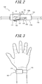
FIG. 3 illustrates an example of a usage state of the electronic device inFIG. 1 ; -
FIG. 4 is an external perspective view schematically illustrating an example of an electronic device according to an embodiment; -
FIG. 5 schematically illustrates a state in which the electronic device ofFIG. 4 is worn; -
FIG. 6 schematically illustrates an exterior portion and a sensor in a front view of the electronic device ofFIG. 4 ; -
FIG. 7 schematically illustrates the positional relationship between the wrist of the subject and a first arm of the sensor in a front view; -
FIG. 8A schematically illustrates the positional relationship between the wrist of the subject, the first arm of the sensor, and the exterior portion of the measurement unit in a front view; -
FIG. 8B schematically illustrates the positional relationship between the wrist of the subject, the first arm of the sensor, and the exterior portion of the measurement unit in a front view; -
FIG. 9 is a functional block diagram of an electronic device; -
FIG. 10 illustrates an example of an estimation method based on pulse waves in an electronic device; -
FIG. 11 illustrates an example of the acceleration pulse wave; -
FIG. 12 illustrates an example of pulse waves acquired by a sensor; -
FIG. 13A illustrates an example of an estimation method, based on a change in pulse waves, in an electronic device; -
FIG. 13B illustrates another example of an estimation method, based on a change in pulse waves, in an electronic device; -
FIG. 14 is a flowchart for deriving an estimation formula used by the electronic device ofFIG. 1 ; -
FIG. 15 illustrates an example pulse wave; -
FIG. 16 illustrates an example of the acceleration pulse wave; -
FIG. 17 illustrates an example pulse wave; -
FIG. 18A is a graph illustrating the preprandial pulse waveform in the present embodiment; -
FIG. 18B is a graph illustrating the postprandial pulse waveform in the present embodiment; -
FIG. 19 illustrates an example of neural network regression analysis; -
FIG. 20 illustrates an example of neural network regression analysis; -
FIG. 21A is a graph illustrating learning data for neural network regression analysis; -
FIG. 21B is a graph illustrating verification data for neural network regression analysis; -
FIG. 22 is a flowchart for estimating a subject's postprandial blood glucose level using an estimation formula; -
FIG. 23 is a flowchart for estimating a subject's postprandial blood glucose level using a plurality of estimation formulas; -
FIG. 24 is a flowchart for deriving an estimation formula used by an electronic device according to a second embodiment; -
FIG. 25 is a flowchart for estimating a subject's postprandial lipid level using the estimation formula derived with the flowchart inFIG. 24 ; -
FIG. 26 schematically illustrates the configuration of a system according to an embodiment; and -
FIG. 27 illustrates an example pulse wave. - The pain involved in collecting a blood sample prevents subjects from estimating their own state of health routinely. Furthermore, an electronic device that only measures pulse is unable to measure the subject's state of health apart from the pulse. The present disclosure therefore provides an electronic device, an estimation system, an estimation method, and an estimation program that can easily estimate a subject's state of health.
- Embodiments are described below in detail with reference to the drawings.
-
FIG. 1 illustrates the schematic configuration of a first example of an electronic device according to an embodiment. Anelectronic device 100 of the first example illustrated inFIG. 1 includes a wearingportion 110 and ameasurement unit 120.FIG. 1 is a view of theelectronic device 100 of the first example from aback face 120a that comes into contact with the measured part. - The
electronic device 100 measures the subject's biological information while theelectronic device 100 is worn by the subject. The biological information measured by theelectronic device 100 includes the subject's pulse wave. In an embodiment, theelectronic device 100 of the first example may acquire the pulse wave while being worn on the subject's wrist. - In an embodiment, the wearing
portion 110 is a straight, elongated band. The pulse wave is, for example, measured in a state in which the subject has wrapped the wearingportion 110 of theelectronic device 100 around the wrist. In greater detail, the subject wraps the wearingportion 110 around the wrist so that theback face 120a of themeasurement unit 120 is in contact with the measured part and then measures the pulse wave. Theelectronic device 100 measures the pulse wave of blood flowing through the ulnar artery or the radial artery of the subject. -
FIG. 2 is a cross-section of theelectronic device 100 of the first example.FIG. 2 illustrates themeasurement unit 120 and the wearingportion 110 around themeasurement unit 120. - The
measurement unit 120 includes theback face 120a in contact with the subject's wrist while worn and afront face 120b opposite theback face 120a. Themeasurement unit 120 includes anopening 111 on theback face 120a side. Asensor 130 includes a first end that touches the subject's wrist when theelectronic device 100 of the first example is worn and a second end in contact with themeasurement unit 120. In a state in which anelastic body 140 is not pressed, the first end of thesensor 130 protrudes from theopening 111 at theback face 120a. The first end of thesensor 130 includes apulse pad 132. The first end of thesensor 130 is displaceable in a direction substantially perpendicular to the plane of theback face 120a. The second end of thesensor 130 is in contact with themeasurement unit 120 via ashaft 133. - The first end of the
sensor 130 is in contact with themeasurement unit 120 via theelastic body 140. The first end of thesensor 130 is displaceable relative to themeasurement unit 120. Theelastic body 140 includes a spring, for example. Theelastic body 140 is not limited to being a spring and can be any other elastic body, such as resin or a sponge. Instead of or along with theelastic body 140, a biasing mechanism such as a torsion coil spring may be provided on therotation shaft 133 of thesensor 130, and thepulse pad 132 of thesensor 130 may be placed in contact with the measured part that is subjected to measurement of the pulse wave of the subject's blood. - A controller, storage, communication interface, power source, notification interface, circuits for causing these components to operate, cables for connecting these components, and the like may be disposed in the
measurement unit 120. - The
sensor 130 includes anangular velocity sensor 131 that detects displacement of thesensor 130. Theangular velocity sensor 131 detects the angular displacement of thesensor 130. The type of sensor provided in thesensor 130 is not limited to theangular velocity sensor 131 and may, for example, be an acceleration sensor, an angle sensor, another motion sensor, or a plurality of these sensors. - The
electronic device 100 of the first example includes aninput interface 141 on thefront face 120b of themeasurement unit 120. Theinput interface 141 receives operation input from the subject and may be configured, for example, using operation buttons (operation keys). Theinput interface 141 may, for example, be configured by a touchscreen. -
FIG. 3 illustrates an example of a usage state of theelectronic device 100 of the first example by the subject. The subject wraps theelectronic device 100 of the first example around the wrist for use. Theelectronic device 100 of the first example is worn in a state such that theback face 120a of themeasurement unit 120 is in contact with the wrist. With theelectronic device 100 of the first example wrapped around the wrist, the position of themeasurement unit 120 can be adjusted so that thepulse pad 132 is in contact with the position of the ulnar artery or the radial artery. - In
FIG. 3 , while theelectronic device 100 of the first example is worn, the first end of thesensor 130 is in contact with the skin above the radial artery, which is the artery on the thumb side of the subject's left hand. The first end of thesensor 130 is in contact with the skin above the subject's radial artery as a result of the elastic force of theelastic body 140 arranged between themeasurement unit 120 and thesensor 130. Thesensor 130 is displaced in accordance with the movement of the subject's radial artery, i.e. pulsation. Theangular velocity sensor 131 detects displacement of thesensor 130 and acquires the pulse wave. The pulse wave refers to a waveform representation of the temporal change, acquired from the body surface, in volume of a blood vessel due to inflow of blood. - Referring again to
FIG. 2 , in a state in which anelastic body 140 is not pressed, the first end of thesensor 130 protrudes from theopening 111. When theelectronic device 100 of the first example is worn by the subject, the first end of thesensor 130 is in contact with the skin above the subject's radial artery, and in accordance with pulsation, theelastic body 140 expands and contracts, displacing the first end of thesensor 130. A component with an appropriate elastic modulus is used for theelastic body 140 so as to expand and contract in accordance with pulsation without inhibiting pulsation. The opening width W of theopening 111 is greater than the vessel diameter, i.e. the radial artery diameter in an embodiment. By theopening 111 being provided in themeasurement unit 120, theback face 120a of themeasurement unit 120 does not compress the radial artery when theelectronic device 100 of the first example is worn. Therefore, theelectronic device 100 of the first example can acquire a pulse wave with little noise, improving measurement accuracy. -
FIG. 3 illustrates an example in which theelectronic device 100 of the first example is worn on the wrist and acquires the pulse wave at the radial artery, but theelectronic device 100 of the first example may, for example, acquire the pulse wave of blood flowing through a carotid artery at the subject's neck. In greater detail, the subject may press thepulse pad 132 lightly against the position of the carotid artery to measure the pulse wave. The subject may also wrap theelectronic device 100 of the first example around the neck so that thepulse pad 132 is at the position of the carotid artery. -
FIG. 4 is an external perspective view schematically illustrating a second example of an electronic device according to an embodiment. Anelectronic device 100 of the second example illustrated inFIG. 4 includes a wearingportion 210, abase 211, and a fixingportion 212 andmeasurement unit 220 attached to thebase 211. - In the present embodiment, the
base 211 is a substantially rectangular flat plate. In the present disclosure, the direction of the short sides of the flat plate-shapedbase 211 is considered the x-axis direction, the direction of the long sides of the flat plate-shapedbase 211 is considered the y-axis direction, and the orthogonal direction of the flat plate-shapedbase 211 is considered the z-axis direction, as illustrated inFIG. 4 . A portion of theelectronic device 100 of the second example is configured to be moveable, as described in the present disclosure. When describing the direction with regard to theelectronic device 100 of the second example in the present disclosure, the x, y, and z-axis directions in the state inFIG. 4 are implied, unless otherwise noted. In the present disclosure, the positive z-axis direction is referred to as up, the negative z-axis direction as down, and the positive x-axis direction as the front of theelectronic device 100 of the second example. - The
electronic device 100 of the second example measures the subject's biological information while the subject wears theelectronic device 100 of the second example using the wearingportion 210. The biological information measured by theelectronic device 100 of the second example is the subject's pulse wave, which is measurable by themeasurement unit 220. As one example, theelectronic device 100 of the second example is described below as being worn on the subject's wrist and acquiring a pulse wave. -
FIG. 5 schematically illustrates a state in which a subject is wearing theelectronic device 100 of the second example inFIG. 4 . The subject can wear theelectronic device 100 as illustrated inFIG. 5 by inserting a wrist into the space formed by the wearingportion 210, thebase 211, and themeasurement unit 220 and fixing the wrist in place with the wearingportion 210. In the example illustrated inFIGS. 4 and5 , the subject wears theelectronic device 100 of the second example by inserting the wrist along the x-axis in the positive x-axis direction through the space formed by the wearingportion 210, thebase 211, and themeasurement unit 220. The subject wears theelectronic device 100 of the second example so that, for example, thepulse pad 132 of themeasurement unit 220, described below, is in contact with the position of the ulnar artery or the radial artery. Theelectronic device 100 of the second example measures the pulse wave of blood flowing through the ulnar artery or the radial artery at the subject's wrist. - The
measurement unit 220 includes abody 221, anexterior portion 222, and asensor 130. Thesensor 130 is attached to thebody 221. Themeasurement unit 220 is attached to thebase 211 via a connectingportion 223. - The connecting
portion 223 may be attached to the base 211 in a rotatable manner along the surface of thebase 211. In other words, in the example inFIG. 4 , the connectingportion 223 may be attached to the base 211 in a rotatable manner in the xy plane relative to thebase 211, as indicated by the arrow A. In this case, theentire measurement unit 220 attached to thebase 211 via the connectingportion 223 is rotatable in the xy plane relative to thebase 211. - The
exterior portion 222 is connected to the connectingportion 223 along a shaft S1 that passes through the connectingportion 223. The shaft S1 is a shaft extending in the x-axis direction. By theexterior portion 222 being connected to the connectingportion 223 in this way, theexterior portion 222 is displaceable relative to the connectingportion 223 along a plane intersecting the xy plane along which thebase 211 extends. In other words, theexterior portion 222 can be inclined about the shaft S1 at a predetermined angle to the xy plane along which thebase 211 extends. Theexterior portion 222 can, for example, be displaced while positioned on a plane having a predetermined inclination relative to the xy plane, such as the yz plane. In the present embodiment, theexterior portion 222 can be connected to the connectingportion 223 in a rotatable manner, in the yz plane orthogonal to the xy plane, about the shaft S1 as indicated by the arrow B inFIG. 4 . - The
exterior portion 222 includes acontact surface 222a that comes in contact with the subject's wrist when theelectronic device 100 of the second example is worn. Theexterior portion 222 may include anopening 225 on thecontact surface 222a side. Theexterior portion 222 may be configured to cover thebody 221. - The
exterior portion 222 may include ashaft 224, extending in the z-axis direction, in an interior space. Thebody 221 includes a hole through which theshaft 224 is passed. Thebody 221 is attached in the interior space of theexterior portion 222 with theshaft 224 passed through the hole. In other words, thebody 221 is attached to theexterior portion 222 in a rotatable manner, in the xy plane, about theshaft 224 relative to theexterior portion 222, as indicated by the arrow C inFIG. 4 . Thebody 221 is thus attached to theexterior portion 222 in a rotatable manner along the xy plane, which is the surface of thebase 211, relative to theexterior portion 222. Thebody 221 is also attached to theexterior portion 222 in a displaceable manner in the up-down direction relative to theexterior portion 222, along theshaft 224, i.e. along the z-axis direction, as indicated by the arrow D inFIG. 4 . - The
sensor 130 is attached to thebody 221. Details of thesensor 130 are described with reference toFIG. 6 , which schematically illustrates theexterior portion 222 and thesensor 130 in a front view of theelectronic device 100 of the second example. InFIG. 6 , the portions of thesensor 130 that overlap with theexterior portion 222 in the front view are indicated by dashed lines. - The
sensor 130 includes afirst arm 134 and asecond arm 135. Thesecond arm 135 is fixed to thebody 221. Anend 135a of thesecond arm 135 at the lower side is connected to anend 134a of thefirst arm 134. Thefirst arm 134 is connected to thesecond arm 135 so that theother end 134b is rotatable in the yz plane with theend 134a as the axis of rotation, as indicated by the arrow E inFIG. 6 . - The
other end 134b of thefirst arm 134 is connected to theother end 135b of thesecond arm 135 at the upper side via theelastic body 140. Thefirst arm 134 is supported by thesecond arm 135 in a state such that thefirst arm 134 is not being pressed by theelastic body 140, and theother side 134b of thesensor 130 is protruding from theopening 225 of theexterior portion 222 towards thecontact surface 222a side. Theelastic body 140 is, for example, a spring. Theelastic body 140 is not limited to being a spring, however, and can be any other elastic body, such as resin or a sponge. Instead of or along with theelastic body 140, a biasing mechanism such as a torsion coil spring may be provided on a rotation shaft S2 of thefirst arm 134, and thepulse pad 132 of thefirst arm 134 may be placed in contact with the measured part that is subjected to measurement of the pulse wave of the subject's blood. - The
pulse pad 132 is connected to theother end 134b of thefirst arm 134. Thepulse pad 132 is the portion placed in contact with the measured part targeted for measurement of the pulse wave of the subject's blood when theelectronic device 100 of the second example is worn. In the present embodiment, thepulse pad 132 is, for example, in contact with the position of the ulnar artery or the radial artery. Thepulse pad 132 may be configured by a material that does not easily absorb changes in body surface due to the subject's pulse. Thepulse pad 132 may be configured by a material that is not painful for the user in a state of contact. For example, thepulse pad 132 may be formed by a cloth bag filled with beads. Thepulse pad 132 may, for example, be configured to be detachable from thefirst arm 134. The subject may, for example, attach onepulse pad 132 to thefirst arm 134 from among a plurality of sizes and/or shapes ofpulse pads 132 in accordance with the size and/or shape of the subject's wrist. This enables the subject to use thepulse pad 132 in accordance with the size and/or shape of the subject's wrist. - The
sensor 130 includes anangular velocity sensor 131 that detects displacement of thefirst arm 134. It suffices for theangular velocity sensor 131 to be capable of detecting the angular displacement of thefirst arm 134. The type of sensor provided in thesensor 130 is not limited to theangular velocity sensor 131 and may, for example, be an acceleration sensor, an angle sensor, another motion sensor, or a plurality of these sensors. - While the
electronic device 100 of the second example is worn in the present embodiment, thepulse pad 132 is in contact with the skin above the radial artery, which is the artery on the thumb side of the subject's right hand, as illustrated inFIG. 5 . The elastic force of theelastic body 140 disposed between thesecond arm 135 and thefirst arm 134 places thepulse pad 132 disposed at theother end 134b of thefirst arm 134 in contact with the skin above the radial artery of the subject. Thefirst arm 134 is displaced in accordance with the movement of the subject's radial artery, i.e. pulsation. Theangular velocity sensor 131 acquires the pulse wave by detecting displacement of thefirst arm 134. The pulse wave refers to a waveform representation of the temporal change in volume of a blood vessel due to inflow of blood, acquired from the body surface. - As illustrated in
FIG. 6 , theother end 134b of thefirst arm 134 protrudes from theopening 225 while theelastic body 140 is not being pressed. When the subject wears theelectronic device 100, thepulse pad 132 connected to thefirst arm 134 comes into contact with the skin above the radial artery of the subject. Theelastic body 140 expands and contracts in accordance with pulsation, and thepulse pad 132 is displaced. A component with an appropriate elastic modulus is used for theelastic body 140 so as to expand and contract in accordance with pulsation without inhibiting pulsation. The opening width W of theopening 225 is sufficiently greater than the vessel diameter, i.e. the radial artery diameter in the present embodiment. By theopening 225 being provided in theexterior portion 222, thecontact surface 222a of theexterior portion 222 does not compress the radial artery when theelectronic device 100 of the second example is worn. Therefore, theelectronic device 100 of the second example can acquire a pulse wave with little noise, improving measurement accuracy. - The fixing
portion 212 is fixed to thebase 211. The fixingportion 212 may include a fixing mechanism for fixing the wearingportion 210. Each functional component used for theelectronic device 100 of the second example to measure the pulse wave may be included inside the wearingportion 210. For example, the fixingportion 212 may include the below-described input interface, controller, power source, storage, communication interface, notification interface, circuits for causing these components to operate, cables for connecting these components, and the like. - The wearing
portion 210 is a mechanism used for fixing the subject's wrist to theelectronic device 100 of the second example. In the example illustrated inFIG. 4 , the wearingportion 210 is a straight, elongated band. The wearingportion 210 in the example illustrated inFIG. 4 is arranged so that oneend 210a is connected to the upper end of themeasurement unit 220, the wearingportion 210 passes through the inside of thebase 211, and anotherend 210b is located in the positive direction of the y-axis. For example, the subject inserts his right wrist into the space formed by the wearingportion 210, thebase 211, and themeasurement unit 220 and pulls theother end 210b of the wearingportion 210 in the positive direction of the y-axis with the left hand while making adjustments so that thepulse pad 132 comes into contact with the skin above the radial artery of the right wrist. The subject pulls theother end 210b enough for the right wrist to be fixed to theelectronic device 100 of the second example and fixes the wearingportion 210 in this state with the fixing mechanism of the fixingportion 212. In this way, the subject can put on theelectronic device 100 of the second example with one hand (the left hand in the present embodiment). The subject can also use the wearingportion 210 to fix the wrist to theelectronic device 100 of the second example, thereby stabilizing the wearing state of theelectronic device 100 of the second example. Consequently, the positional relationship between the wrist and theelectronic device 100 of the second example is less likely to change during measurement. This enables stable measurement of the pulse wave and improves measurement accuracy. - Next, movement of the moveable portion of the
electronic device 100 of the second example at the time of wearing of theelectronic device 100 of the second example is described. - To wear the
electronic device 100 of the second example, the subject inserts the wrist along the x-axis direction into the space formed by the wearingportion 210, thebase 211, and themeasurement unit 220, as described above. Themeasurement unit 220 is configured to be rotatable in the direction of the arrow A ofFIG. 4 relative to thebase 211. At this time, the subject can therefore insert the wrist while rotating themeasurement unit 220 in the direction indicated by the arrow A ofFIG. 4 . By themeasurement unit 220 being configured in this way to be rotatable, the subject can insert the wrist while appropriately changing the direction of themeasurement unit 220 in accordance with the positional relationship between the subject and theelectronic device 100 of the second example. This makes it easier for the subject to wear theelectronic device 100 of the second example. - After inserting the wrist into the space formed by the wearing
portion 210, thebase 211, and themeasurement unit 220, the subject places thepulse pad 132 in contact with the skin above the radial artery of the wrist. Thebody 221 is configured to be displaceable in the direction of the arrow D ofFIG. 4 . Thefirst arm 134 of thesensor 130 connected to thebody 221 is therefore also displaceable in the direction of the arrow D, which is the z-axis direction, as illustrated inFIG. 7 . Therefore, the subject can displace thefirst arm 134 in the direction of the arrow D in accordance with the size, thickness, and the like of the subject's wrist so that thepulse pad 132 comes into contact with the skin above the radial artery. The subject can fix thebody 221 at the position of displacement. Theelectronic device 100 of the second example thus facilitates adjustment of the position of thesensor 130 to a suitable position for measurement. Theelectronic device 100 of the second example thereby improves measurement accuracy. Thebody 221 has been described as displaceable in the z-axis direction in the example inFIG. 4 , but thebody 221 is not necessarily configured to be displaceable in the z-axis direction. It suffices for thebody 221 to be configured to be capable of adjusting the position in accordance with the size, thickness, and the like of the wrist, for example. Thebody 221 may, for example, be configured to be displaceable in a direction intersecting the xy plane, which is the surface of thebase 211. - When the
pulse pad 132 is in contact with the skin above the radial artery in a direction orthogonal to the skin surface, the pulsation transmitted to thefirst arm 134 increases. In other words, when the displacement direction of the pulse pad 132 (the direction indicated by the arrow E ofFIG. 6 ) is a direction orthogonal to the skin surface, the pulsation transmitted to thefirst arm 134 increases, and the accuracy with which pulsation is acquired can increase. In theelectronic device 100 of the second example, thebody 221 and thesensor 130 connected to thebody 221 are configured to be rotatable about theshaft 224 with respect to theexterior portion 222, as indicated by the arrow C ofFIG. 4 . The subject can thereby adjust the direction of thesensor 130 so that the displacement direction of thepulse pad 132 is a direction orthogonal to the skin surface. In other words, theelectronic device 100 of the second example enables adjustment of the direction of thesensor 130 so that the displacement direction of thepulse pad 132 is a direction orthogonal to the skin surface. Theelectronic device 100 of the second example thereby enables adjustment of the direction of thesensor 130 in accordance with the shape of the subject's wrist. This facilitates transmission of a change in the pulsation of the subject to thefirst arm 134. Theelectronic device 100 of the second example thereby improves measurement accuracy. - The subject places the
pulse pad 132 in contact with the skin above the radial artery of the wrist, as illustrated inFIG. 8A , and then pulls theother end 210b of the wearingportion 210 to fix the wrist to theelectronic device 100 of the second example. Theexterior portion 222 is configured to be rotatable in the direction of the arrow B inFIG. 4 . Therefore, when the subject pulls the wearingportion 210, theexterior portion 222 rotates about the shaft S1, and the upper end is displaced in the negative direction of the y-axis. In other words, the upper end of theexterior portion 222 is displaced in the negative direction of the y-axis, as illustrated inFIG. 8B . Thefirst arm 134 is connected to thesecond arm 135 via theelastic body 140. Therefore, when the upper end of theexterior portion 222 is displaced in the negative direction of the y-axis, thepulse pad 132 is biased towards the radial artery by the elastic force of theelastic body 140. Consequently, thepulse pad 132 can more reliably capture changes in the pulse. Theelectronic device 100 of the second example thereby improves measurement accuracy. - The rotation direction of the exterior portion 222 (the direction indicated by arrow B) and the rotation direction of the first arm 134 (the direction indicated by the arrow E) may be substantially parallel. As the rotation direction of the
exterior portion 222 and the rotation direction of thefirst arm 134 are closer to being parallel, the elastic force of theelastic body 140 acts more efficiently on thefirst arm 134 when the upper end of theexterior portion 222 is displaced in the negative direction of the y-axis. The range over which the rotation direction of theexterior portion 222 and the rotation direction of thefirst arm 134 are substantially parallel includes the range over which the elastic force of theelastic body 140 acts on thefirst arm 134 when the upper end of theexterior portion 222 is displaced in the negative direction of the y-axis. - Here, the
surface 222b on the front side of theexterior portion 222 illustrated inFIG. 8A is substantially rectangular, with the long sides in the up-down direction. Thesurface 222b includes anotch 222c at the upper end on the side in the negative direction of the y-axis. Thenotch 222c makes thesurface 222b less likely to contact the skin above the radial artery when the upper end of theexterior portion 222 is displaced in the negative direction of the y-axis, as illustrated inFIG. 8B . This helps to prevent pulsation of the radial artery from being hindered by contact with thesurface 222b. - Furthermore, when the upper end of the
exterior portion 222 is displaced in the negative direction of the y-axis as illustrated inFIG. 8B , theend 222d at the lower side of thenotch 222c contacts the wrist at a different position than the radial artery. When theend 222d comes into contact with the wrist, theexterior portion 222 is no longer displaced in the negative direction of the y-axis beyond the contact position. Theend 222d can therefore prevent theexterior portion 222 from being displaced beyond a predetermined position. If theexterior portion 222 were displaced in the negative direction of the y-axis beyond a predetermined position, thefirst arm 134 would be strongly pressed towards the radial artery by the elastic force of theelastic body 140. Pulsation of the radial artery would therefore tend to be hindered. Since theexterior portion 222 includes theend 222d, theelectronic device 100 of the second example can prevent an excessive pressure from acting on the radial artery from thefirst arm 134, making the pulsation of the radial artery less likely to be hindered. In this way, theend 222d functions as a stopper that restricts the range over which theexterior portion 222 is displaceable. - In the present embodiment, the rotation shaft S2 of the
first arm 134 may be disposed at a position away from the side of thesurface 222b in the negative direction of the y-axis, as illustrated inFIG. 8A . When the rotation shaft S2 is disposed near the side of thesurface 222b in the negative direction of the y-axis, the changes in pulsation of the radial artery might not be captured accurately due to thefirst arm 134 touching the subject's wrist. The position of the rotation shaft S2 away from the side of thesurface 222b in the negative direction of the y-axis can reduce the probability of thefirst arm 134 touching the wrist, thereby making it easier for thefirst arm 134 to capture changes in pulsation more accurately. - The subject pulls the
other end 210b of the wearingportion 210 and fixes the wearingportion 210 with the fixing mechanism of the fixingportion 212 to wear theelectronic device 100 of the second example on the wrist. Once worn on the wrist in this way, theelectronic device 100 of the second example measures the subject's pulse wave by thefirst arm 134 changing in the direction indicated by the arrow E together with changes in pulsation. - The above-described first and second examples of the
electronic device 100 merely illustrate example configurations of theelectronic device 100. Theelectronic device 100 is therefore not limited to the configurations illustrated by the first and second examples. It suffices for theelectronic device 100 to include a configuration capable of measuring the subject's pulse wave. -
FIG. 9 is a functional block diagram of theelectronic device 100 of the first or second example. Theelectronic device 100 includes thesensor 130, theinput interface 141, acontroller 143, apower source 144, a storage 145, acommunication interface 146, and anotification interface 147. In theelectronic device 100 of the first example, thecontroller 143,power source 144, storage 145,communication interface 146, andnotification interface 147 may be included inside themeasurement unit 120 or the wearingportion 110. In theelectronic device 100 of the second example, thecontroller 143,power source 144, storage 145,communication interface 146, andnotification interface 147 may be included inside the fixingportion 212. - The
sensor 130 includes theangular velocity sensor 131, detects pulsation from the measured part, and acquires the pulse wave. - The
controller 143 is a processor that, starting with the functional blocks of theelectronic device 100, controls and manages theelectronic device 100 overall. Furthermore, thecontroller 143 is a processor that, using the acquired pulse wave, estimates the blood glucose level of the subject. Thecontroller 143 is configured by a processor, such as a central processing unit (CPU), that executes programs prescribing control procedures and programs for estimating the blood glucose level of the subject. These programs may, for example, be stored on a storage medium such as the storage 145. Based on an index calculated from the pulse wave, thecontroller 143 estimates a state related to the subject's glucose metabolism, lipid metabolism, or the like. Thecontroller 143 may notify thenotification interface 147 of data. - The
power source 144 for example includes a lithium-ion battery and a control circuit for charging and discharging the battery. Thepower source 144 supplies power to theelectronic device 100 overall. Thepower source 144 is not limited to being a secondary cell such as a lithium-ion battery and may, for example, be a primary cell such as a button cell. - The storage 145 stores programs and data. The storage 145 may include a non-transitory storage medium, such as a semiconductor storage medium or a magnetic storage medium. The storage 145 may also include a plurality of types of storage media. The storage 145 may include a combination of a portable storage medium, such as a memory card, optical disc, or magneto-optical disc, and an apparatus for reading the storage medium. The storage 145 may include a storage device used as a volatile storage area, such as random access memory (RAM). The storage 145 stores a variety of information, programs for causing the
electronic device 100 to operate, and the like and also functions as a working memory. The storage 145 may, for example, store the measurement result of the pulse wave acquired by thesensor 130. - The
communication interface 146 exchanges a variety of data with an external apparatus by wired or wireless communication. For example, thecommunication interface 146 communicates with an external apparatus that stores the biological information of the subject to manage the state of health. Thecommunication interface 146 transmits, to the external apparatus, the measurement result of the pulse wave measured by theelectronic device 100 and the state of health estimated by theelectronic device 100. - The
notification interface 147 provides notification of information by sound, vibration, images, and the like. Thenotification interface 147 may include a speaker, a vibration unit, and a display device. The display device can, for example, be a liquid crystal display (LCD), an organic electro-luminescence display (OELD), an inorganic electro-luminescence display (IELD), or the like. In an embodiment, thenotification interface 147 provides notification of the state of the subject's glucose metabolism or lipid metabolism. - The
electronic device 100 according to an embodiment estimates the state of glucose metabolism. In an embodiment, theelectronic device 100 estimates the blood glucose level as the state of glucose metabolism. - The
electronic device 100 estimates the subject's blood glucose level based on an estimation formula derived by regression analysis, for example. Theelectronic device 100 stores the estimation formula for estimating the blood glucose level based on the pulse wave in the storage 145, for example, in advance. Theelectronic device 100 estimates the blood glucose level using this estimation formula. - Estimation theory related to estimating the blood glucose level based on the pulse wave is now described. As a result of an increase in the blood glucose level after a meal, the blood fluidity reduces (viscosity increases), blood vessels dilate, and the amount of circulating blood increases. Vascular dynamics and hemodynamics are determined so as to balance these states. The reduction in blood fluidity occurs, for example, because of an increase in the viscosity of blood plasma or a reduction in the deformability of red blood cells. Dilation of blood vessels occurs for reasons such as secretion of insulin, secretion of digestive hormones, and a rise in body temperature. When blood vessels dilate, the pulse rate increases to suppress a reduction in blood pressure. Furthermore, the increase in the amount of circulating blood compensates for blood consumption for digestion and absorption. The postprandial vascular dynamics and hemodynamics due to these causes are also reflected in the pulse wave. The
electronic device 100 can therefore estimate the blood glucose level based on the pulse wave. - An estimation formula for estimating the blood glucose level based on the above estimation theory can be derived by performing regression analysis on sample data of postprandial pulse waves and blood glucose levels obtained from a plurality of subjects. By applying the derived estimation formula to the index in accordance with the subject's pulse wave at the time of estimation, the subject's blood glucose level can be estimated. If the estimation formula is derived in particular by performing regression analysis using sample data for which variation in the blood glucose level is close to a normal distribution, the blood glucose level of the subject being tested can be estimated. The estimation formula may, for example, be derived by partial least squares (PLS) regression analysis. In PLS regression analysis, a regression coefficient matrix is calculated by using the covariance of the outcome variable (feature amount of the estimation target) and the explanatory variable (feature amount used for estimation) to perform multiple regression analysis by adding to the variable in order from the component with the highest correlation between the outcome variable and the explanatory variable.
- "Preprandial" as used in the present disclosure refers to before a meal is taken, such as when fasting. "Postprandial" as used in the present disclosure refers to a time after a meal is taken, such as the time when the effects of the meal are reflected in the blood at a predetermined time after the meal is taken. As described in the present embodiment, "postprandial" in the case of the
electronic device 100 estimating the blood glucose level may refer to the time at which the blood glucose level increases (for example, approximately one hour after the start of the meal). -
FIG. 10 illustrates an example pulse wave to illustrate an example of an estimation method based on pulse waves. The estimation formula for estimating blood glucose level is, for example, derived by regression analysis related to age, an index SI indicating the rising of a pulse wave (rising index), an augmentation index (AI), and pulse rate PR. - The rising index SI is derived in accordance with the waveform indicated in the area D1 of
FIG. 10 . In greater detail, the rising index SI is the ratio of the first local minimum to the first local maximum in the acceleration pulse wave yielded by the second derivative of the pulse wave. For example, for the acceleration pulse wave illustrated as an example inFIG. 11 , the rising index SI is expressed as b/a. The rising index SI decreases because of a reduction in fluidity of the blood, secretion of insulin, dilation (relaxation) of blood vessels due to increased body temperature, and the like after a meal. In the acceleration pulse wave b/a, b is negative, and a is positive. In this case, b/a is negative. A smaller value of b/a means that b is growing in the negative direction. - The AI is an index represented by the ratio between the magnitudes of the forward wave and the reflected wave of the pulse wave. A method of deriving AI is described with reference to
FIG. 12 , which illustrates an example of pulse waves acquired at the wrist using theelectronic device 100.FIG. 12 illustrates the case of using theangular velocity sensor 131 as means for detecting the pulsation.FIG. 12 is a time integration of the angular velocity acquired by theangular velocity sensor 131, with the horizontal axis representing time and the vertical axis representing the angle. Since the acquired pulse wave may, for example, include noise that is due to body movement of the subject, the pulse wave may be corrected by a filter that removes the direct current (DC) component, so as to extract only the pulsation component. - Propagation of the pulse wave is a phenomenon in which pulsation due to blood extruded from the heart is transmitted through artery walls or blood. The pulsation due to blood pumped from the heart reaches the peripheries of limbs as a forward wave, a portion of which is reflected at locations such as where a blood vessel branches, or where the diameter of a blood vessel changes, and returns as a reflected wave. AI is the quotient when the magnitude of the reflected wave is divided by the magnitude of the forward wave and is expressed as Ain = (PRn - PSn)/(PFn - PSn). Here, AIn is the AI for each pulse beat. AI may, for example, be calculated by measuring the pulse wave for several seconds and calculating the average AIave of the AIn for each pulse beat (n = an integer from 1 to n). The AI is derived from the waveform indicated in area D2 of
FIG. 10 . The AI reduces because of a reduction in fluidity of the blood, dilation of blood vessels due to increased body temperature, and the like after a meal. - The pulse rate PR is derived from the period TPR of the pulse wave illustrated in
FIG. 10 . The pulse rate PR rises after a meal. - The
electronic device 100 can estimate the blood glucose level using the estimation formula derived from the rising index SI, the AI, and the pulse rate PR. -
FIGS. 13A and 13B illustrate another example of an estimation method based on pulse waves.FIG. 13A illustrates a pulse wave, andFIG. 13B illustrates the result of performing a fast Fourier transform (FFT) on the pulse wave ofFIG. 13A . The estimation formula for estimating the blood glucose level is, for example, derived by regression analysis related to a fundamental and harmonic component (Fourier coefficients) that are derived by an FFT. The peak value in the result of the FFT illustrated inFIG. 13B changes in accordance with change in the waveform of the pulse wave. Therefore, the blood glucose level can be estimated with an estimation formula derived using the Fourier coefficients. - Based on the above-described rising index SI, AI, pulse rate PR, Fourier coefficients, and the like, the
electronic device 100 uses the estimation formula to estimate the blood glucose level of the subject. - Here, a method for deriving an estimation formula for the case of the
electronic device 100 estimating the subject's blood glucose level is described. The estimation formula need not be derived by theelectronic device 100 and may be derived in advance using another computer or the like. In the present disclosure, the device that derives the estimation formula is referred to as an estimation formula derivation apparatus. The derived estimation formula is, for example, stored in the storage 145 in advance, before the subject estimates the blood glucose level with theelectronic device 100. -
FIG. 14 is a flowchart for deriving an estimation formula used by theelectronic device 100. The estimation formula is derived by performing regression analysis based on sample data obtained by measuring a subject's postprandial pulse wave using a pulse wave meter and measuring the subject's postprandial blood glucose level using a blood glucose meter. The acquired sample data are not limited to after a meal. It suffices to use data for time slots with large variation in the blood glucose level. - During derivation of the estimation formula, first, information related to the subject's postprandial pulse wave, as measured by a pulse wave meter, is inputted into the estimation formula derivation apparatus (step S101).
- Information related to the subject's postprandial blood glucose level, as measured by a blood glucose meter, is also inputted into the estimation formula derivation apparatus (step S102). The blood glucose level inputted in step S102 is, for example, measured with a blood glucose meter by taking a blood sample. The age of the subject for each set of sample data may also be inputted in step S101 or step S102.
- The estimation formula derivation apparatus determines whether the number of samples in the sample data inputted in step S101 and step S102 is N or greater, which is an amount sufficient for regression analysis (step S103). The sample number N can be determined appropriately and can be 100, for example. When determining that the number of samples is less than N (No), the estimation formula derivation apparatus repeats step S101 and step S102 until the number of samples becomes N or greater. Conversely, when determining that the number of samples is N or greater (Yes), the estimation formula derivation apparatus proceeds to step S104 and calculates the estimation formula.
- During calculation of the estimation formula, the estimation formula derivation apparatus analyzes the inputted postprandial pulse wave (step S104). For example, the estimation formula derivation apparatus analyzes the rising index SI, the AI, and the pulse rate PR of the postprandial pulse wave. The estimation formula derivation apparatus may analyze the pulse wave by performing FFT analysis.
- The estimation formula derivation apparatus then performs regression analysis (step S105). The outcome variable in the regression analysis is the postprandial blood glucose level. The explanatory variables in the regression analysis are, for example, the age inputted in step S101 or step S102 and the rising index SI, the AI, and the pulse rate PR of the postprandial pulse wave analyzed in step S104. When the estimation formula derivation apparatus performs FFT analysis in step S104, the explanatory variables may, for example, be Fourier coefficients calculated as the result of the FFT analysis.
- The estimation formula derivation apparatus derives an estimation formula for estimating the postprandial blood glucose level based on the result of regression analysis (step S106).
- Depending on the waveform of the pulse wave, the AI may be difficult to detect.
FIG. 15 illustrates an example pulse wave. The pulse wave illustrated inFIG. 15 is greatly affected by the reflected wave, represented by the second peak.FIG. 16 illustrates the acceleration pulse wave of the pulse wave illustrated inFIG. 15 . The effect of the reflected wave also appears in the waveform of the acceleration pulse wave, as illustrated inFIG. 16 , for example. When AI becomes small, AI may be difficult to detect or may disappear and be undetectable. Examples of when AI becomes small are when blood vessels dilate or the blood glucose level is high. - Therefore, instead of or in addition to the AI, the estimation formula may be derived using another index. The use of another index AIt is now described as an example. AIt is the rate of change in the pulse wave at a predetermined time after the peak of the pulse wave.
FIG. 17 illustrates an example pulse wave to illustrate the AIt. The AIt is the ratio of P3 to P1, where P1 is the height of the peak of the pulse wave, and P3 is the height of the pulse wave after a predetermined time Δt from the point in time when P1 appears. In other words, AIt = P3/P1. The predetermined time Δt may be a time before the effect of the reflected wave appears. For example, if the pulse wave velocity is 10 m/sec, and the distance from the heart to the main reflection point inside the body is 1 m round trip, then the time until the reflected wave makes a round trip is 100 msec. The predetermined time Δt may, for example, be 100 msec calculated in this way. In other words, suppose the main reflection point of the reflected wave of AI is the abdominal aortic bifurcation. Also suppose that the round-trip distance between the heart and the abdominal aortic bifurcation is 2L, and the pulse wave velocity is PWV. This yields Δt = 2L/PWV. The pulse wave velocity of the abdominal aorta is generally thought to be 10 m/sec. The value of L is generally 50 cm. Accordingly, Δt = 2L/PWV = 100/1000 = 0.1 sec. - Naturally, the predetermined time Δt may vary depending on individual differences in the round-trip distance 2L and the pulse wave velocity PWV, the measurement time, the state of health, or other factors. For example, the round-trip distance 2L and the pulse wave velocity PWV may vary from the aforementioned example values due to age, sex, health status, or other factors. The predetermined time Δt may therefore vary from 100 msec and may be a numerical value in a certain range. For example, the predetermined time Δt may be 100 msec or less, or 100 msec or more. Setting the predetermined time Δt in this way facilitates accurate calculation of the AIt even when the reflected wave disappears. Depending on the waveform of the pulse wave, the use of AIt as an index related to pulse wave can improve the estimation accuracy of the subject's blood glucose level as compared to when AI is used. The predetermined time Δt is the time around which the reflected wave appears. The effect of the reflected wave is often included in the AIt.
- With reference to
FIGS. 18A and 18B , the change from the preprandial pulse waveform to the postprandial pulse waveform is now described.FIGS. 18A and 18B are graphs illustrating the change from the preprandial pulse waveform to the postprandial pulse waveform in the present embodiment. InFIGS. 18A and 18B , the horizontal axis represents time, and the vertical axis represents the pulse wave.FIG. 18A is the preprandial pulse waveform, andFIG. 18B is the pulse waveform one hour after a meal. Both pulse waveforms are for the pulse wave of the same individual. As illustrated inFIG. 18B , the postprandial AI may become small and difficult to detect. As the blood glucose level increases, AI further decreases or disappears. - The estimation formula derivation apparatus can derive an estimation formula with the flowchart described with reference to
FIG. 14 , using the AIt as one explanatory variable. In the present embodiment, the estimation formula derivation apparatus is described below as deriving an estimation formula with the above-described age, rising index SI, AI, pulse rate PR, and also AIt as explanatory variables. - The estimation formula is not necessarily derived by PLS regression analysis. The estimation formula may be derived using another method. For example, the estimation formula may be derived by neural network regression analysis.
-
FIG. 19 illustrates an example of neural network regression analysis.FIG. 19 schematically illustrates a neural network in which the input layer is five neurons and the output layer is one neuron. The five neurons of the input layer are age, rising index SI, AI, AIt, and pulse rate PR. The neuron of the output layer is the blood glucose level. The neural network illustrated inFIG. 19 includes five intermediate layers between the input layer and the output layer:intermediate layer 1,intermediate layer 2,intermediate layer 3,intermediate layer 4, andintermediate layer 5.Intermediate layer 1 has 5 nodes,intermediate layer 2 has 4 nodes,intermediate layer 3 has 3 nodes,intermediate layer 4 has 2 nodes, andintermediate layer 5 has 1 node. Each node of the intermediate layers receives input of the sum of components of data that are outputted from the preceding layer and weighted. Each node of the intermediate layers outputs a value yielded by performing a predetermined calculation (bias) on the inputted data. During neural network regression analysis, backpropagation is used to compare the estimated output value with the correct output value, and the weighting and bias are adjusted in the network to minimize the difference between these two values. The estimation formula can be derived in this way by neural network regression analysis. - The neural network regression analysis used in the present embodiment is not limited to the case illustrated in
FIG. 19 . For example, the example of neural network regression analysis illustrated inFIG. 20 may be used. InFIG. 20 , the four neurons of the input layer are age, pulse rate PR, AI, and AIt. The neuron of the output layer is the blood glucose level. -
FIGS. 21A and21B illustrate the learning data and verification data used in the neural network regression analysis of the present embodiment illustrated inFIG. 19 .FIG. 21A is a graph illustrating learning data for the neural network regression analysis of the present embodiment, andFIG. 21B is a graph illustrating verification data for neural network regression analysis. - Next, an example process for estimating the subject's blood glucose level using an estimation formula is described.
FIG. 22 is a flowchart for estimating a subject's postprandial blood glucose level using the derived estimation formula. - First, the
electronic device 100 receives input of the subject's age based on operation of theinput interface 141 by the subject (step S201). - After the subject eats a meal, the
electronic device 100 measures the subject's postprandial pulse wave based on operation by the subject (step S202). - The
electronic device 100 then analyzes the measured postprandial pulse wave (step S203). For example, theelectronic device 100 analyzes the rising index SI, the AI, the AIt, and the pulse rate PR related to the measured postprandial pulse wave. - The
electronic device 100 applies the subject's age received as input in step S201 and the rising index SI, the AI, the AIt, and the pulse rate PR analyzed in step S203 to the estimation formula and estimates the subject's postprandial blood glucose level (step S204). The subject is notified of the estimated postprandial blood glucose level by thenotification interface 147 of theelectronic device 100, for example. - In this way, the
electronic device 100 according to the present embodiment uses an estimation formula derived based on the postprandial pulse wave and blood glucose level to estimate the subject's postprandial blood glucose level based on the subject's measured postprandial pulse wave. Theelectronic device 100 can therefore estimate the postprandial blood glucose level rapidly and in a non-invasive manner. Consequently, theelectronic device 100 can easily estimate the subject's state of health. - As an index related to pulse wave, the AIt is not affected by the disappearance of the reflected wave as compared to the AI. Use of the AIt, therefore, can improve the estimation accuracy of the subject's blood glucose level. Even when the reflected wave AI is difficult to detect, the AIt can be detected stably, thereby improving accuracy.
- The
electronic device 100 is not limited to the postprandial blood glucose level and may estimate the subject's blood glucose level at any timing. Theelectronic device 100 can also estimate the blood glucose level at any timing rapidly and in a non-invasive manner. - The method of estimating the postprandial blood glucose level by the
electronic device 100 is not limited to the above-described method. For example, each time theelectronic device 100 estimates the subject's postprandial blood glucose level, theelectronic device 100 may select one estimation formula from among a plurality of estimation formulas and estimate the subject's postprandial blood glucose level using the selected estimation formula. A plurality of estimation formulas are derived in advance in this case. - A plurality of estimation formulas may, for example, be derived in accordance with the content of meals. The content of a meal may, for example, include the quantity and quality of the meal. The quantity of the meal may, for example, include the weight of the meal. The quality of the meal may, for example, include the menu item, ingredients (food), cooking method, or the like.
- The content of the meal may, for example, be classified into a plurality of categories. The content of the meal may, for example, be classified into the categories of noodles, set meals, bowls, or the like. The same number of estimation formulas as the number of categories of the content of a meal may, for example, be derived. In other words, when the content of the meal is classified into three categories, an estimation formula may be derived in association with each category. In this case, the number of derived estimation formulas is three. The
electronic device 100 uses the estimation formula, among the plurality of estimation formulas, corresponding to the content of the subject's meal to estimate the postprandial blood glucose level. - An example process for estimating the subject's blood glucose level using an estimation formula in the case of a plurality of derived estimation formulas is now described.
FIG. 23 is a flowchart for estimating a subject's postprandial blood glucose level using a plurality of derived estimation formulas. - The
electronic device 100 receives input of the subject's age based on operation of theinput interface 141 by the subject (step S301). - The
electronic device 100 receives input of the content of the meal based on operation of theinput interface 141 by the subject (step S302). Theelectronic device 100 can receive input of the content of the meal from the subject by various methods. For example, when theelectronic device 100 includes a display device, theelectronic device 100 may receive input by displaying contents of meals (for example, categories) in a manner selectable by the subject and prompting the subject to select the content of the meal closest to the meal the subject is about to eat. Theelectronic device 100 may, for example, receive input by having the subject list the content of the meal using theinput interface 141. When theelectronic device 100 includes an imaging unit such as a camera, theelectronic device 100 may, for example, receive input by using the imaging unit to capture an image of the meal about to be eaten. In this case, theelectronic device 100 may, for example, estimate the content of the meal by image analysis on the captured image that is received. - The
electronic device 100 measures the subject's postprandial pulse wave based on operation by the subject (step S303). - The
electronic device 100 analyzes the measured pulse wave (step S304). For example, theelectronic device 100 analyzes the rising index SI, the AI, the AIt, and the pulse rate PR related to the measured pulse wave. - The
electronic device 100 selects one estimation formula from among the plurality of estimation formulas based on the meal content received in step S302 (step S305). For example, theelectronic device 100 selects the estimation formula associated with the category closest to the inputted content of the meal. - The
electronic device 100 applies the subject's age received as input in step S301 and the rising index SI, the AI, the AIt, and the pulse rate PR analyzed in step S304 to the estimation formula and estimates the subject's postprandial blood glucose level (step S306). The subject is notified of the estimated postprandial blood glucose level by thenotification interface 147 of theelectronic device 100, for example. - The postprandial blood glucose level may change depending on the content of the meal. Nevertheless, the
electronic device 100 can estimate the blood glucose level more accurately in accordance with the content of the meal by estimating the postprandial blood glucose level using an estimation formula, among a plurality of estimation formulas, that corresponds to the content of the meal. - In the first embodiment, the case of the
electronic device 100 estimating the subject's postprandial blood glucose level has been described. In the second embodiment, an example of theelectronic device 100 estimating the subject's postprandial lipid level is described. Here, the lipid level includes neutral lipids, total cholesterol, HDL cholesterol, LDL cholesterol, and the like. In the description of the present embodiment, a description of points that are similar to the first embodiment is omitted as appropriate. - The
electronic device 100 stores estimation formulas for estimating the lipid level based on the pulse wave in the storage 145, for example, in advance. Theelectronic device 100 estimates the lipid level using these estimation formulas. - The estimation theory related to estimating the lipid level based on pulse wave is similar to the estimation theory for blood glucose level described in the first embodiment. In other words, a change in the lipid level of the blood is also reflected in the waveform of the pulse wave. Therefore, the
electronic device 100 can acquire the pulse wave and estimate the lipid level based on the acquired pulse wave. -
FIG. 24 is a flowchart for deriving an estimation formula used by theelectronic device 100 according to the present embodiment. In the present embodiment as well, the estimation formula is derived by performing regression analysis, such as PLS regression analysis or neural network regression analysis, based on sample data. In the present embodiment, the estimation formula is derived based on the postprandial pulse wave as the sample data. "Postprandial" as used in the present embodiment may refer to a time when the lipid level is higher at a predetermined time after a meal is taken (for example, approximately three hours after the start of a meal). If the estimation formula is derived in particular by performing regression analysis using sample data for which variation in the lipid level is close to a normal distribution, the lipid level at any timing can be estimated for the subject being tested. - During derivation of the estimation formula, first, information related to the subject's postprandial pulse wave, as measured by a pulse wave meter, is inputted into the estimation formula derivation apparatus (step S401).
- Information related to the subject's postprandial lipid level, as measured by a lipid measurement apparatus, is also inputted into the estimation formula derivation apparatus (step S402). The age of the subject for each set of sample data may also be inputted in steps S401 and S402.
- The estimation formula derivation apparatus determines whether the number of samples in the sample data inputted in step S401 and step S402 is N or greater, which is an amount sufficient for regression analysis (step S403). The sample number N can be determined appropriately and can be 100, for example. When determining that the number of samples is less than N (No), the estimation formula derivation apparatus repeats step S401 and step S402 until the number of samples becomes N or greater. Conversely, when determining that the number of samples is N or greater (Yes), the estimation formula derivation apparatus proceeds to step S404 and calculates the estimation formula.
- During calculation of the estimation formula, the estimation formula derivation apparatus analyzes the inputted postprandial pulse wave (step S404). In the present embodiment, the estimation formula derivation apparatus analyzes the rising index SI, the AI, the AIt, and the pulse rate PR of the postprandial pulse wave. The estimation formula derivation apparatus may analyze the pulse wave by performing FFT analysis.
- The estimation formula derivation apparatus then performs regression analysis (step S405). The outcome variable in the regression analysis is the postprandial lipid level. The explanatory variables in the regression analysis are, for example, the age inputted in step S401 or step S402 and the rising index SI, the AI, the AIt, and the pulse rate PR of the postprandial pulse wave analyzed in step S404. When the estimation formula derivation apparatus performs FFT analysis in step S404, the explanatory variables may, for example, be Fourier coefficients calculated as the result of the FFT analysis.
- The estimation formula derivation apparatus derives an estimation formula for estimating the postprandial lipid level based on the result of regression analysis (step S406).
- Next, the process for estimating the subject's lipid level using an estimation formula is described.
FIG. 25 is a flowchart for estimating a subject's postprandial lipid level using the estimation formula derived with the flowchart inFIG. 24 , for example. - First, the
electronic device 100 receives input of the subject's age in response to operation of theinput interface 141 by the subject (step S501). - The
electronic device 100 also measures the subject's postprandial pulse wave based on operation by the subject (step S502). - Next, the
electronic device 100 analyzes the measured pulse wave (step S503). For example, theelectronic device 100 analyzes the rising index SI, the AI, the AIt, and the pulse rate PR related to the measured pulse wave. - The
electronic device 100 estimates the subject's postprandial lipid level by applying the rising index SI, the AI, the AIt, and the pulse rate PR analyzed in step S503 and the subject's age to the estimation formula derived with the flowchart ofFIG. 24 (step S504). The subject is notified of the estimated postprandial lipid level by thenotification interface 147 of theelectronic device 100, for example. - In this way, the
electronic device 100 according to the present embodiment uses an estimation formula derived based on the postprandial pulse wave and lipid level to estimate the subject's postprandial lipid level based on the subject's measured postprandial pulse wave. Theelectronic device 100 can therefore estimate the postprandial lipid level rapidly and in a non-invasive manner. Consequently, theelectronic device 100 can easily estimate the subject's state of health. As an index related to pulse wave, the AIt is less affected than the AI by the reflected wave in the pulse wave. Use of the AIt, therefore, can improve the estimation accuracy of the subject's lipid level. - As described in the example of estimating the blood glucose level, the lipid level may also be estimated by selecting one estimation formula from among a plurality of estimation formulas and using the selected estimation formula to estimate the lipid level.
- In the above embodiments, examples of the
electronic device 100 estimating the blood glucose level and the lipid level have been described, but the blood glucose level and the lipid level are not necessarily estimated by theelectronic device 100. An example of an apparatus other than theelectronic device 100 estimating the blood glucose level and the lipid level is described below. -
FIG. 26 illustrates the schematic configuration of a system according to an embodiment. The system according to the embodiment illustrated inFIG. 26 includes anelectronic device 100, an information processing apparatus (such as a server) 151, amobile terminal 150, and a communication network. As illustrated inFIG. 26 , the pulse wave measured by theelectronic device 100 is transmitted to theinformation processing apparatus 151 over a communication network and is stored on theinformation processing apparatus 151 as personal information of the subject. On theinformation processing apparatus 151, the subject's blood glucose level or lipid level is estimated by comparison with the subject's past acquired information and with a variety of databases. Theinformation processing apparatus 151 may further prepare appropriate advice for the subject. Theinformation processing apparatus 151 replies to themobile terminal 150 in the subject's possession with estimation results and advice. Themobile terminal 150 can construct a system to provide notification, via the display of themobile terminal 150, of the received estimation results and advice. Information from a plurality of users can be collected on theinformation processing apparatus 151 by use of the communication function of theelectronic device 100, thereby further improving the estimation accuracy. Furthermore, since themobile terminal 150 is used as notification means, theelectronic device 100 does not require thenotification interface 147 and can be further reduced in size. The calculation load on thecontroller 143 of theelectronic device 100 can also be reduced, since the subject's blood glucose level or lipid level is estimated on theinformation processing apparatus 151. The subject's past acquired information can also be stored on theinformation processing apparatus 151, thereby reducing the load on the storage 145 of theelectronic device 100. Therefore, theelectronic device 100 can be further reduced in size and complexity. The processing speed for calculation also improves. - In the system according to the present embodiment, the
electronic device 100 and themobile terminal 150 have been illustrated as connected over the communication network via theinformation processing apparatus 151, but a system according to the present disclosure is not limited to this configuration. Theelectronic device 100 and themobile terminal 150 may be connected directly over the communication network without use of theinformation processing apparatus 151. - Characteristic embodiments have been described for a complete and clear disclosure. The appended claims, however, are not limited to the above embodiments and are to be construed as encompassing all of the possible modifications and alternate configurations that a person of ordinary skill in the art could make within the scope of the fundamental features indicated in the present disclosure.
- For example, in the above embodiments, the
sensor 130 has been described as being provided with theangular velocity sensor 131, but theelectronic device 100 according to the present disclosure is not limited to this case. Thesensor 130 may be provided with an optical pulse wave sensor constituted by an optical emitter and an optical detector or may be provided with a pressure sensor. Furthermore, theelectronic device 100 is not limited to being worn on the wrist. It suffices for thesensor 130 to be placed on an artery, such as on the neck, ankle, thigh, ear, or the like. - For example, in the above embodiments, the explanatory variables in the regression analysis, such as PLS regression analysis or neural network regression analysis, have been described as being age, rising index SI, AI, AIt, and pulse rate PR. The explanatory variables need not, however, include all five of these.
- For example, the explanatory variables of regression analysis, such as PLS regression analysis or neural network regression analysis, need not include an index determined based on the acceleration pulse wave. The index determined based on the acceleration pulse wave is, for example, the rising index SI. For example, when the effect of the reflected wave on the pulse wave is large, as described with reference to
FIGS. 15 and 16 , the effect of the reflected wave is also evident in the acceleration pulse wave. The estimation accuracy of the subject's blood glucose level or lipid level may worsen when the effect of the reflected wave is evident in the acceleration pulse wave in this way. An index determined based on the acceleration pulse wave need not be used as an explanatory variable in such a case. When the acceleration pulse wave b/a is not used as an explanatory variable in PLS regression analysis or neural network regression analysis, then age, pulse rate, AI, AIt, and the like can be appropriately selected as explanatory variables. - The explanatory variables may include variables other than these five variables. For example, the explanatory variables may include sex, an index determined based on the velocity pulse wave yielded by the first derivative of the pulse wave, or the like. The explanatory variables may, for example, include an index determined based on pulse. The index based on pulse may, for example, include the ejection time (ET) or the time DWt from heart chamber ejection until a dicrotic wave (DW), examples of which are illustrated in
FIG. 27 . The explanatory variables may, for example, include the fasting blood glucose level (such as the blood glucose level measured by blood sampling or the blood glucose level measured in advance during a physical examination). - The estimation formula has been described in the above embodiments as being derived based on the postprandial pulse wave and the blood glucose level or lipid level. The estimation formula is not, however, necessarily derived based on the postprandial pulse wave and the blood glucose level or lipid level. The estimation formula may, for example, be derived from an appropriate combination of the preprandial and postprandial pulse waves and the preprandial and postprandial blood glucose level or lipid level.
-
- 100
- Electronic device
- 110, 210
- Wearing portion
- 111, 225
- Opening
- 120, 220
- Measurement unit
- 120a
- Back face
- 120b
- Front face
- 130
- Sensor
- 131
- Angular velocity sensor
- 132
- Pulse pad
- 133, 224
- Shaft
- 134
- First arm
- 135
- Second arm
- 140
- Elastic body
- 141
- Input interface
- 143
- Controller
- 144
- Power source
- 145
- Storage
- 146
- Communication interface
- 147
- Notification interface
- 150
- Mobile terminal
- 151
- Information processing apparatus
- 211
- Base
- 212
- Fixing portion
- 221
- Body
- 222
- Exterior portion
- 222a
- Contact surface
- 222b
- Surface
- 222c
- Notch
- 222d
- End
- 223
- Connecting portion
Claims (16)
- An electronic device comprising:a sensor configured to acquire a pulse wave of a subject; anda controller configured to analyze, based on the pulse wave of the subject acquired by the sensor, a rate of change in the pulse wave at a predetermined time after a point in time exhibiting a peak of the pulse wave and to estimate a blood glucose level of the subject based on the rate of change.
- The electronic device of claim 1, wherein the predetermined time is given by Δt = 2L/PWV, where 2L is a round-trip distance between a heart and a reflection point, the reflection point is an abdominal aortic bifurcation, and PWV is a pulse wave velocity.
- The electronic device of claim 1, wherein the predetermined time is substantially 100 msec.
- The electronic device of claim 1, wherein the controller is configured to estimate the blood glucose level of the subject by applying the rate of change to an estimation formula.
- The electronic device of claim 4, wherein the estimation formula is derived based on a postprandial pulse wave and a postprandial blood glucose level.
- The electronic device of claim 4, wherein the controller is configured to estimate the postprandial blood glucose level by using an estimation formula, among a plurality of estimation formulas, corresponding to a content of a meal of the subject.
- The electronic device of claim 6, wherein each estimation formula among the plurality of estimation formulas corresponds to a category of the content of the meal.
- The electronic device of claim 4, wherein the estimation formula is derived by PLS regression analysis or neural network regression analysis.
- The electronic device of claim 4, wherein the controller is configured to estimate the blood glucose level of the subject by applying an index determined based on a velocity pulse wave to the estimation formula.
- An electronic device comprising:a sensor configured to acquire a pulse wave of a subject; anda controller configured to analyze, based on the pulse wave of the subject acquired by the sensor, a rate of change in the pulse wave at a predetermined time after a point in time exhibiting a peak of the pulse wave and to estimate a lipid level of the subject based on the rate of change.
- An estimation system comprising an electronic device and an information processing apparatus connected communicably with each other,
wherein the electronic device comprises a sensor configured to acquire a pulse wave of a subject; and
the information processing apparatus comprises a controller configured to analyze, based on the pulse wave of the subject acquired by the sensor, a rate of change in the pulse wave at a predetermined time after a point in time exhibiting a peak of the pulse wave and to estimate a blood glucose level of the subject based on the rate of change. - An estimation system comprising an electronic device and an information processing apparatus connected communicably with each other,
wherein the electronic device comprises a sensor configured to acquire a pulse wave of a subject; and
the information processing apparatus comprises a controller configured to analyze, based on the pulse wave of the subject acquired by the sensor, a rate of change in the pulse wave at a predetermined time after a point in time exhibiting a peak of the pulse wave and to estimate a lipid level of the subject based on the rate of change. - An estimation method to be executed by an electronic device, the estimation method comprising:acquiring a pulse wave of a subject;analyzing, based on the pulse wave of the subject, a rate of change in the pulse wave at a predetermined time after a point in time exhibiting a peak of the pulse wave; andestimating a blood glucose level of the subject based on the rate of change.
- An estimation method to be executed by an electronic device, the estimation method comprising:acquiring a pulse wave of a subject;analyzing, based on the pulse wave of the subject, a rate of change in the pulse wave at a predetermined time after a point in time exhibiting a peak of the pulse wave; andestimating a lipid level of the subject based on the rate of change.
- An estimation program for causing an electronic device to execute the steps of:acquiring a pulse wave of a subject;analyzing, based on the pulse wave of the subject, a rate of change in the pulse wave at a predetermined time after a point in time exhibiting a peak of the pulse wave; andestimating a blood glucose level of the subject based on the rate of change.
- An estimation program for causing an electronic device to execute the steps of:acquiring a pulse wave of a subject;analyzing, based on the pulse wave of the subject, a rate of change in the pulse wave at a predetermined time after a point in time exhibiting a peak of the pulse wave; andestimating a lipid level of the subject based on the rate of change.
Applications Claiming Priority (2)
| Application Number | Priority Date | Filing Date | Title |
|---|---|---|---|
| JP2018044750A JP6815344B2 (en) | 2018-03-12 | 2018-03-12 | Electronics, estimation systems, estimation methods and estimation programs |
| PCT/JP2019/003709 WO2019176362A1 (en) | 2018-03-12 | 2019-02-01 | Electronic device, estimation system, estimation method, and estimation program |
Publications (2)
| Publication Number | Publication Date |
|---|---|
| EP3766409A1 true EP3766409A1 (en) | 2021-01-20 |
| EP3766409A4 EP3766409A4 (en) | 2021-12-08 |
Family
ID=67906509
Family Applications (1)
| Application Number | Title | Priority Date | Filing Date |
|---|---|---|---|
| EP19767305.6A Pending EP3766409A4 (en) | 2018-03-12 | 2019-02-01 | Electronic device, estimation system, estimation method, and estimation program |
Country Status (5)
| Country | Link |
|---|---|
| US (2) | US11464431B2 (en) |
| EP (1) | EP3766409A4 (en) |
| JP (1) | JP6815344B2 (en) |
| CN (2) | CN117694880A (en) |
| WO (1) | WO2019176362A1 (en) |
Families Citing this family (3)
| Publication number | Priority date | Publication date | Assignee | Title |
|---|---|---|---|---|
| KR102576126B1 (en) * | 2019-09-19 | 2023-09-06 | 삼성전자주식회사 | Apparatus and method for estimating bio-information |
| JP7083195B1 (en) | 2021-03-02 | 2022-06-10 | Ssst株式会社 | Biological information calculation system |
| JP6918394B1 (en) * | 2021-03-02 | 2021-08-11 | Ssst株式会社 | Biological information calculation system |
Family Cites Families (19)
| Publication number | Priority date | Publication date | Assignee | Title |
|---|---|---|---|---|
| US4564018A (en) * | 1982-10-28 | 1986-01-14 | Storz Instrument Company | Ultrasonic system for obtaining ocular measurements |
| JP3763687B2 (en) * | 1998-12-25 | 2006-04-05 | 三井金属鉱業株式会社 | Blood glucose level measuring device |
| JP2001170016A (en) * | 1999-12-16 | 2001-06-26 | Seiko Instruments Inc | Sphygmograph |
| JP2002360530A (en) | 2001-06-11 | 2002-12-17 | Waatekkusu:Kk | Pulse wave sensor and pulse rate detector |
| JP3533406B2 (en) * | 2001-07-02 | 2004-05-31 | コーリンメディカルテクノロジー株式会社 | Atherosclerosis evaluation device |
| US20060224070A1 (en) * | 2005-04-05 | 2006-10-05 | Sharrock Nigel E | System and method for non-invasive cardiovascular assessment from supra-systolic signals obtained with a wideband external pulse transducer in a blood pressure cuff |
| US7651466B2 (en) * | 2005-04-13 | 2010-01-26 | Edwards Lifesciences Corporation | Pulse contour method and apparatus for continuous assessment of a cardiovascular parameter |
| JP5146995B2 (en) * | 2007-10-25 | 2013-02-20 | テルモ株式会社 | Blood pressure measurement device and control method thereof |
| WO2009086455A1 (en) * | 2007-12-28 | 2009-07-09 | Nellcor Puritan Bennett Llc | Airway instability index calculation system and method |
| JP5503234B2 (en) * | 2009-09-18 | 2014-05-28 | シスメックス株式会社 | Postprandial blood glucose estimation device, postprandial blood glucose estimation method, and computer program |
| US20150031964A1 (en) * | 2012-02-22 | 2015-01-29 | Aclaris Medical, Llc | Physiological signal detecting device and system |
| JP6209395B2 (en) * | 2013-02-27 | 2017-10-04 | 株式会社デルタツーリング | Biological state estimation device and computer program |
| CN107405114B (en) * | 2015-03-13 | 2022-12-02 | 国立大学法人信州大学 | Non-invasive blood glucose level measuring method and non-invasive blood glucose level measuring apparatus |
| US10765331B2 (en) * | 2015-04-02 | 2020-09-08 | Microsoft Technology Licensing, Llc | Wearable pulse sensing device signal quality estimation |
| CN111297332A (en) * | 2015-04-28 | 2020-06-19 | 京瓷株式会社 | Electronic device and system |
| JP2017153875A (en) * | 2016-03-04 | 2017-09-07 | セイコーエプソン株式会社 | Biological information measurement device and biological information measurement method |
| JP6636872B2 (en) * | 2016-06-30 | 2020-01-29 | 京セラ株式会社 | Electronic equipment and estimation system |
| JP6783599B2 (en) | 2016-09-16 | 2020-11-11 | 株式会社東芝 | Arithmetic logic unit for air conditioning control, arithmetic method for air conditioning control, and arithmetic program for air conditioning control |
| KR102498120B1 (en) * | 2017-10-17 | 2023-02-09 | 삼성전자주식회사 | Apparatus and method for correcting error of bio-information sensor, apparatus and method for estimating bio-information |
-
2018
- 2018-03-12 JP JP2018044750A patent/JP6815344B2/en active Active
-
2019
- 2019-02-01 WO PCT/JP2019/003709 patent/WO2019176362A1/en unknown
- 2019-02-01 CN CN202410079819.5A patent/CN117694880A/en active Pending
- 2019-02-01 EP EP19767305.6A patent/EP3766409A4/en active Pending
- 2019-02-01 US US16/970,250 patent/US11464431B2/en active Active
- 2019-02-01 CN CN201980015822.8A patent/CN111787853B/en active Active
-
2022
- 2022-09-07 US US17/930,342 patent/US20230000404A1/en active Pending
Also Published As
| Publication number | Publication date |
|---|---|
| CN117694880A (en) | 2024-03-15 |
| EP3766409A4 (en) | 2021-12-08 |
| US11464431B2 (en) | 2022-10-11 |
| US20230000404A1 (en) | 2023-01-05 |
| US20210137425A1 (en) | 2021-05-13 |
| CN111787853A (en) | 2020-10-16 |
| CN111787853B (en) | 2024-02-02 |
| JP6815344B2 (en) | 2021-01-20 |
| WO2019176362A1 (en) | 2019-09-19 |
| JP2019154736A (en) | 2019-09-19 |
Similar Documents
| Publication | Publication Date | Title |
|---|---|---|
| JP7054710B2 (en) | Electronic devices and systems | |
| US20230000404A1 (en) | Electronic device, estimation system, estimation method, and estimation program | |
| JP6884718B2 (en) | Electronics, estimation systems, estimation methods and estimation programs | |
| EP3756539A1 (en) | Electronic device, estimation system, estimation method, and estimation program | |
| JP6930009B2 (en) | Electronics, estimation systems, estimation methods and estimation programs | |
| JP6873307B2 (en) | Electronics, estimation systems, estimation methods and estimation programs | |
| JP6993261B2 (en) | Electronic devices, estimation systems, estimation methods and estimation programs | |
| JP2023052660A (en) | Electronic equipment, estimation system, estimation method and estimation program |
Legal Events
| Date | Code | Title | Description |
|---|---|---|---|
| STAA | Information on the status of an ep patent application or granted ep patent |
Free format text: STATUS: THE INTERNATIONAL PUBLICATION HAS BEEN MADE |
|
| PUAI | Public reference made under article 153(3) epc to a published international application that has entered the european phase |
Free format text: ORIGINAL CODE: 0009012 |
|
| STAA | Information on the status of an ep patent application or granted ep patent |
Free format text: STATUS: REQUEST FOR EXAMINATION WAS MADE |
|
| 17P | Request for examination filed |
Effective date: 20200824 |
|
| AK | Designated contracting states |
Kind code of ref document: A1 Designated state(s): AL AT BE BG CH CY CZ DE DK EE ES FI FR GB GR HR HU IE IS IT LI LT LU LV MC MK MT NL NO PL PT RO RS SE SI SK SM TR |
|
| AX | Request for extension of the european patent |
Extension state: BA ME |
|
| DAV | Request for validation of the european patent (deleted) | ||
| DAX | Request for extension of the european patent (deleted) | ||
| A4 | Supplementary search report drawn up and despatched |
Effective date: 20211105 |
|
| RIC1 | Information provided on ipc code assigned before grant |
Ipc: A61B 5/145 20060101ALI20211101BHEP Ipc: A61B 5/02 20060101AFI20211101BHEP |
|
| P01 | Opt-out of the competence of the unified patent court (upc) registered |
Effective date: 20230508 |
|
| STAA | Information on the status of an ep patent application or granted ep patent |
Free format text: STATUS: EXAMINATION IS IN PROGRESS |