EP3766321B1 - Work vehicle and deviation amount calculation program - Google Patents
Work vehicle and deviation amount calculation program Download PDFInfo
- Publication number
- EP3766321B1 EP3766321B1 EP19768156.2A EP19768156A EP3766321B1 EP 3766321 B1 EP3766321 B1 EP 3766321B1 EP 19768156 A EP19768156 A EP 19768156A EP 3766321 B1 EP3766321 B1 EP 3766321B1
- Authority
- EP
- European Patent Office
- Prior art keywords
- work vehicle
- target
- rectangle
- crop rows
- crop
- Prior art date
- Legal status (The legal status is an assumption and is not a legal conclusion. Google has not performed a legal analysis and makes no representation as to the accuracy of the status listed.)
- Active
Links
Images


Classifications
-
- G—PHYSICS
- G01—MEASURING; TESTING
- G01C—MEASURING DISTANCES, LEVELS OR BEARINGS; SURVEYING; NAVIGATION; GYROSCOPIC INSTRUMENTS; PHOTOGRAMMETRY OR VIDEOGRAMMETRY
- G01C21/00—Navigation; Navigational instruments not provided for in groups G01C1/00 - G01C19/00
- G01C21/005—Navigation; Navigational instruments not provided for in groups G01C1/00 - G01C19/00 with correlation of navigation data from several sources, e.g. map or contour matching
-
- A—HUMAN NECESSITIES
- A01—AGRICULTURE; FORESTRY; ANIMAL HUSBANDRY; HUNTING; TRAPPING; FISHING
- A01B—SOIL WORKING IN AGRICULTURE OR FORESTRY; PARTS, DETAILS, OR ACCESSORIES OF AGRICULTURAL MACHINES OR IMPLEMENTS, IN GENERAL
- A01B69/00—Steering of agricultural machines or implements; Guiding agricultural machines or implements on a desired track
- A01B69/001—Steering by means of optical assistance, e.g. television cameras
-
- A—HUMAN NECESSITIES
- A01—AGRICULTURE; FORESTRY; ANIMAL HUSBANDRY; HUNTING; TRAPPING; FISHING
- A01B—SOIL WORKING IN AGRICULTURE OR FORESTRY; PARTS, DETAILS, OR ACCESSORIES OF AGRICULTURAL MACHINES OR IMPLEMENTS, IN GENERAL
- A01B69/00—Steering of agricultural machines or implements; Guiding agricultural machines or implements on a desired track
- A01B69/007—Steering or guiding of agricultural vehicles, e.g. steering of the tractor to keep the plough in the furrow
- A01B69/008—Steering or guiding of agricultural vehicles, e.g. steering of the tractor to keep the plough in the furrow automatic
-
- G—PHYSICS
- G01—MEASURING; TESTING
- G01C—MEASURING DISTANCES, LEVELS OR BEARINGS; SURVEYING; NAVIGATION; GYROSCOPIC INSTRUMENTS; PHOTOGRAMMETRY OR VIDEOGRAMMETRY
- G01C21/00—Navigation; Navigational instruments not provided for in groups G01C1/00 - G01C19/00
- G01C21/20—Instruments for performing navigational calculations
-
- G—PHYSICS
- G05—CONTROLLING; REGULATING
- G05D—SYSTEMS FOR CONTROLLING OR REGULATING NON-ELECTRIC VARIABLES
- G05D1/00—Control of position, course, altitude or attitude of land, water, air or space vehicles, e.g. using automatic pilots
- G05D1/20—Control system inputs
- G05D1/24—Arrangements for determining position or orientation
- G05D1/242—Means based on the reflection of waves generated by the vehicle
-
- G—PHYSICS
- G05—CONTROLLING; REGULATING
- G05D—SYSTEMS FOR CONTROLLING OR REGULATING NON-ELECTRIC VARIABLES
- G05D1/00—Control of position, course, altitude or attitude of land, water, air or space vehicles, e.g. using automatic pilots
- G05D1/60—Intended control result
- G05D1/646—Following a predefined trajectory, e.g. a line marked on the floor or a flight path
-
- G—PHYSICS
- G01—MEASURING; TESTING
- G01S—RADIO DIRECTION-FINDING; RADIO NAVIGATION; DETERMINING DISTANCE OR VELOCITY BY USE OF RADIO WAVES; LOCATING OR PRESENCE-DETECTING BY USE OF THE REFLECTION OR RERADIATION OF RADIO WAVES; ANALOGOUS ARRANGEMENTS USING OTHER WAVES
- G01S17/00—Systems using the reflection or reradiation of electromagnetic waves other than radio waves, e.g. lidar systems
- G01S17/88—Lidar systems specially adapted for specific applications
- G01S17/89—Lidar systems specially adapted for specific applications for mapping or imaging
-
- G—PHYSICS
- G01—MEASURING; TESTING
- G01S—RADIO DIRECTION-FINDING; RADIO NAVIGATION; DETERMINING DISTANCE OR VELOCITY BY USE OF RADIO WAVES; LOCATING OR PRESENCE-DETECTING BY USE OF THE REFLECTION OR RERADIATION OF RADIO WAVES; ANALOGOUS ARRANGEMENTS USING OTHER WAVES
- G01S7/00—Details of systems according to groups G01S13/00, G01S15/00, G01S17/00
- G01S7/48—Details of systems according to groups G01S13/00, G01S15/00, G01S17/00 of systems according to group G01S17/00
- G01S7/4802—Details of systems according to groups G01S13/00, G01S15/00, G01S17/00 of systems according to group G01S17/00 using analysis of echo signal for target characterisation; Target signature; Target cross-section
-
- G—PHYSICS
- G05—CONTROLLING; REGULATING
- G05D—SYSTEMS FOR CONTROLLING OR REGULATING NON-ELECTRIC VARIABLES
- G05D2107/00—Specific environments of the controlled vehicles
- G05D2107/20—Land use
- G05D2107/21—Farming, e.g. fields, pastures or barns
-
- G—PHYSICS
- G05—CONTROLLING; REGULATING
- G05D—SYSTEMS FOR CONTROLLING OR REGULATING NON-ELECTRIC VARIABLES
- G05D2109/00—Types of controlled vehicles
- G05D2109/10—Land vehicles
-
- G—PHYSICS
- G05—CONTROLLING; REGULATING
- G05D—SYSTEMS FOR CONTROLLING OR REGULATING NON-ELECTRIC VARIABLES
- G05D2111/00—Details of signals used for control of position, course, altitude or attitude of land, water, air or space vehicles
- G05D2111/10—Optical signals
- G05D2111/17—Coherent light, e.g. laser signals
Definitions
- This invention relates to a work vehicle and a deviation amount calculation program.
- Patent Literature 1 discloses a work machine that travels along a furrow.
- an automatic travel control of the work machine is performed on the basis of the angle of the work machine to a ridge and a position deviation amount of the work machine from the center of the ridge.
- Patent Literature 2 discloses a harvester that performs an automatic travel control when the traveling direction of the machine approaches one side of the right and left crop rows.
- Patent Literature 1 Disclosed in Patent Literature 1 is a technique directed to a field where there are ridges the edges of which can be detected relatively easily. For example, in the case of an orchard without ridges, a trunk is hidden by the leaves and branches of a crop, and thus it may not be possible to accurately detect a crop row. Therefore, it is difficult to apply the travel control such as that in Patent Literature 1 to a field without ridges.
- Patent Literature 2 an image acquired by an imaging means is rotated, an amount of deviation of a work machine from the center position of a ridge is calculated on the basis of this rotated image, and an angle in the traveling direction of the work machine with respect to the ridge is calculated. This is a process on condition that ridges extend straight along the traveling direction of the work machine. Therefore, in Patent Literature 2, when the ridges do not extend straight, it is difficult to identify the position and angle (direction) of the work machine.
- Patent Literature 2 Even in Patent Literature 2, the position and direction of the harvester when each crop row does not extend straight are not considered.
- Documents JP H01 206904 A and US 2010/104194 A1 disclose a work vehicle configured to travel in a field where a plurality of crop rows are planted.
- the work vehicle comprises a distance sensor configured to acquire information on a distance from the work vehicle to each of a plurality of objects present in the field.
- a work vehicle is a work vehicle that is configured to travel in a field where a plurality of crop rows are planted, and that includes a distance sensor configured to acquire information on a distance from the work vehicle to each of a plurality of objects present in the field, a rectangle identification unit configured to estimate the plurality of crop rows on a basis of the distance information and identify a rectangle whose opposite sides are adjacent crop rows of the estimated crop rows, a target setting unit configured to set a target travel route of the work vehicle between the adjacent crop rows on a basis of the rectangle, and a position deviation calculation unit configured to estimate a current position of the work vehicle between the adjacent crop rows on a basis of the rectangle, and calculate a deviation amount of the current position from the target travel route.
- a rectangle whose opposite sides are adjacent crop rows is identified, and the target travel route is set on the basis of the identified rectangle, and at the same time the current position of the work vehicle is estimated. Therefore, for example, when the slopes of adjacent crop rows change in the middle, such as when the adjacent crop rows bend in the middle, a rectangle according to a slope near the work vehicle in the adjacent crop rows is identified. This makes it possible to set a target travel route between adjacent crop rows corresponding to changes in the slopes of these crop rows, and to estimate the position of the work vehicle between the adjacent crop rows. In other words, with this configuration, it is possible to identify the position of the work vehicle itself between the crop rows regardless of the condition of a field such as bending of the crop rows.
- One embodiment of the present invention further includes a position correction unit configured to correct a position of the work vehicle between the crop rows in such a manner that the position approaches the target travel route, on a basis of the deviation amount calculated by the position deviation calculation unit.
- the position of the work vehicle can be corrected so as to approach the target travel route, and thus the work vehicle can be caused to automatically travel along the target travel route.
- One embodiment of the present invention further includes a direction sensor configured to detect a direction of the work vehicle.
- the target setting unit is configured to also set a target direction of the work vehicle.
- the work vehicle further includes a direction deviation calculation unit configured to calculate a deviation amount of a current direction of the work vehicle detected by the direction sensor from the target direction.
- One embodiment of the present invention further includes a direction correction unit configured to correct a direction of the work vehicle between the crop rows in such a manner that the direction approaches the target direction, on a basis of the deviation amount calculated by the direction deviation calculation unit.
- the rectangle identification unit repeatedly identifies the rectangle while the work vehicle travels between the crop rows, the target direction setting unit sets the target direction on a basis of the rectangle each time the rectangle is identified, and the direction deviation calculation unit calculates a deviation amount of a current direction of the work vehicle detected by the direction sensor from the target direction, each time the target direction is set.
- a deviation amount calculation program is a deviation amount calculation program that sets a target travel route of a work vehicle in a field where a plurality of crop rows are planted and calculates a deviation amount of the work vehicle from the target travel route.
- the deviation amount calculation program causes a computer to function as a rectangle identification unit for estimating the plurality of crop rows on a basis of information on a distance from the work vehicle to each of a plurality of objects present in the field and identifying a rectangle whose opposite sides are adjacent crop rows of the estimated crop rows, a target setting unit for setting a target travel route of the work vehicle, between the adjacent crop rows, on a basis of the rectangle, and a position deviation calculation unit for estimating a current position between the adjacent crop rows on a basis of the rectangle and calculate a deviation amount of the current position from the target travel route.
- this deviation amount calculation program it is possible to automatically set a target travel route of a work vehicle between adjacent crop rows and to acquire a deviation amount of the current position of the work vehicle from the target travel route.
- a rectangle whose opposite sides are adjacent crop rows is identified, and the target travel route is set on the basis of the identified rectangle, and at the same time the current position of the work vehicle is estimated. Therefore, for example, when the slopes of adjacent crop rows change in the middle, such as when the adjacent crop rows bend in the middle, a rectangle according to a slope near the work vehicle in the adjacent crop rows is identified. This makes it possible to set a target travel route between adjacent crop rows corresponding to changes in the slopes of these crop rows, and to estimate the position of the work vehicle between the adjacent crop rows. In other words, with this configuration, it is possible to identify its own position of the work vehicle between the crop rows regardless of the condition of a field such as bending of the crop rows.
- FIG. 1 is a side view illustrating a schematic configuration of a work vehicle according to an embodiment of the present invention.
- FIG. 2 is a front view illustrating a schematic configuration of the work vehicle of FIG. 1 .
- a work vehicle 1 is, in this embodiment, a work vehicle for spraying a chemical liquid.
- the work vehicle 1 includes a traveling device 2, a machine body frame 3 supported on the traveling device 2, and a chemical liquid spraying device 4 provided on the machine body frame 3.
- the traveling device 2 is a crawler type, and includes right and left traveling devices 2L and 2R.
- the traveling device 2 may be a wheel type.
- the schematic representation of a vehicle including a wheel type traveling device may be used as a schematic representation of the work vehicle 1.
- An engine 5 as a drive source is disposed at the rear of the machine body frame 3.
- a support frame 6 is provided at the front of the machine body frame 3.
- the support frame 6 includes a pair of right and left masts 6A and 6B supported by the machine body frame 3, a first coupling member 6C that couples the upper ends of these masts 6A and 6B, and a second coupling member 6D that couples a length intermediate portions of these masts 6A and 6B.
- the chemical liquid spraying device 4 includes a chemical liquid tank 7, a nozzle unit 8, and a pump unit 9.
- the chemical liquid tank 7 is disposed in the front-rear central portion on the machine body frame 3.
- the chemical liquid tank 7 stores a chemical liquid.
- the chemical liquid may be any liquid that is sprayed on crops or soil, and includes a pesticide, water, and the like.
- the nozzle unit 8 is attached to a position near the upper end of the support frame 6.
- the nozzle unit 8 is a hollow body that extends in the right-left direction and includes nozzles 8a and 8b for spouting the chemical liquid at both ends.
- the nozzle unit 8 is formed with a chemical liquid inlet (not illustrated).
- a pump 9A (see FIG. 4 ) which is rotationally driven by the power of the engine 5, a clutch mechanism 9B that transmits or shuts off the rotational force of the engine 5 to the pump 9A (see FIG. 4 ), and the like are included.
- the suction port of the pump 9A is connected to the chemical liquid tank 7 via a hose 10.
- the discharge port of the pump 9A is connected to the chemical liquid inlet of the nozzle unit 8 via a hose 11.
- the work vehicle 1 is equipped with a distance sensor 13 for measuring a distance to an object and a direction sensor (posture sensor) 14 (see FIG. 4 ) for detecting a direction (posture) of the work vehicle 1.
- the distance sensor 13 is disposed at a width center position of the front of the work vehicle 1.
- the distance sensor 13 may be any sensor that can measure a distance to an object, and for example, a sensor that measures a distance to an object with the use of laser light, a sensor that measures a distance to an object with the use of a camera, or the like may be used.
- a light, detection and ranging, or laser imaging detection and ranging (LIDAR) that measures a distance from a time it takes for a laser light to be illuminated in a pulse form and to be reflected by an object and return is used.
- LIDAR laser imaging detection and ranging
- a scan sensor LIDAR is used that can detect the direction of an object by scanning a laser light by changing its direction with a movable mirror.
- a gyro sensor, a geomagnetic sensor, an inertial measurement unit (IMU), or the like can be used as the direction sensor (posture sensor) 14.
- IMU inertial measurement unit
- the work vehicle 1 is provided with a crawler control mechanism 15 (see FIG. 4 ) that transmits the driving force of the engine 5 to the right and left traveling devices 2L and 2R to independently control the right and left traveling devices 2L and 2R.
- the crawler control mechanism 15 is a mechanism for driving the right and left traveling devices 2L and 2R independently to thereby move the work vehicle 1 forward, backward, and turn. Specifically, when the right and left traveling devices 2L and 2R are rotationally driven in a same direction and at a same speed by the crawler control mechanism 15, the work vehicle 1 moves forward or backward. Meanwhile, when the right and left traveling devices 2L and 2R are rotationally driven in a same direction at a different speed or the right and left traveling devices 2L and 2R are rotationally driven in an opposite direction by the crawler control mechanism 15, the work vehicle 1 turns.
- the work vehicle 1 automatically travels in a field H where a crop S is planted in a row and sprays a chemical liquid on the crop S.
- the crop S is a fruit tree and the field H is an orchard.
- the row of the crop S is referred to as a crop row L.
- the row of the crop S arranged vertically is the crop row L.
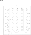
- five crop rows L1 to L5 are laterally planted at intervals. In each crop row L1 to L5, a plurality of crops S are arranged at substantially equal intervals.
- crop rows L1 to L5 are referred to as a first crop row L1, a second crop row L2, a third crop row L3, a fourth crop row L4, and a fifth crop row L5 in order from the left.
- the lower side end of FIG. 3 is called a front side end
- the upper side end of FIG. 3 is called a back side end.
- the work vehicle 1 automatically travels between crop rows toward the back side end while using, for example, a vicinity of the front side end between the first crop row L1 and the second crop row L2, as an automatic travel start position and setting a target travel route between these crop rows.
- the work vehicle 1 reaches the back side end between the crop rows, the work vehicle 1 turns to the right in the traveling direction, and moves to the back side end between the second crop row L2 and the third crop row L3. Then, the work vehicle 1 automatically travels between crop rows toward the front side end while setting the target travel route between the second crop row L2 and the third crop row L3.
- the work vehicle 1 When the work vehicle 1 reaches the front side end between the crop rows L2 and L3, the work vehicle 1 turns to the left toward the traveling direction and moves to the front side end between the third crop row L3 and the fourth crop row L4. Then, the work vehicle 1 automatically travels between crop rows toward the back side end while setting the target travel route between the third crop row L3 and the fourth crop row L4. By the same operation, the work vehicle 1 moves as illustrated by the broken line in FIG. 3 . Then, for example, after the work vehicle 1 reaches the front side end between the fourth crop row L4 and the fifth crop row L5 and turns to the left toward the traveling direction, the automatic traveling is stopped. During automatic traveling, the pump 9A is driven via the clutch mechanism 9B, and the chemical liquid is ejected from the nozzles 8a and 8b.
- the end on the side where the work vehicle 1 starts traveling may be referred to as a traveling start end between the crop rows, and the end on the side opposite to the traveling start end may be called a traveling termination end between the crop rows.
- an interval W between adjacent crop rows may be called a row interval.
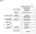
- FIG. 4 is a block diagram illustrating a main electrical configuration of the work vehicle 1.
- the work vehicle 1 includes a control device 30 for controlling the operation of the work vehicle 1.
- the distance sensor 13 Connected to the control device 30 are the distance sensor 13, a direction sensor 14, an engine controller 21, a travel controller 22, a clutch actuator 23, a storage unit 24, and the like.
- the distance sensor 13 detects information on a distance from the work vehicle to each of a plurality of objects present in the field H.
- the main target of the plurality of objects is the crop S.
- the direction sensor 14 is, as described above, for detecting the direction of the work vehicle 1.
- the engine controller 21 controls the number of revolutions of the engine 5, or the like. Specifically, the engine controller 21 controls a common rail device 16 as a fuel injection device provided in the engine 5, thereby controlling the number of revolutions of the engine 5. The engine controller 21 controls the common rail device 16, and thereby can also stop the supply of fuel to the engine 5 and stop the drive of the engine 5.
- the travel controller 22 controls forward, backward, turning, and stopping of the work vehicle 1 by controlling the crawler control mechanism 15.
- the clutch actuator 23 is for fastening and releasing the clutch mechanism 9B in the pump unit 9.
- the storage unit 24 includes a storage device such as a hard disk and a non-volatile memory.
- the control device 30 includes a microcomputer including a central processing unit (CPU) and a memory (read-only memory, or ROM, random-access memory, or RAM, etc.) 31.
- the control device 30 includes an automatic travel control unit 32 for causing the work vehicle 1 to automatically travel along a target travel route while setting the target travel route between adjacent crop rows L in the field H.
- the automatic travel control unit 32 includes a rectangle identification unit 41, a target setting unit 42, a deviation calculation unit 43, and a correction unit 44.
- the rectangle identification unit 41 estimates the plurality of crop rows on the basis of information on a distance from the work vehicle 1 to each of a plurality of objects present in the field H and identifies a rectangle whose opposite sides are adjacent crop rows of the estimated crop rows.
- the information on the distance from the work vehicle 1 to each of the plurality of objects present in the field H is the distance information to each object detected by the distance sensor 13. The operation of the rectangle identification unit 41 will be described in detail below.
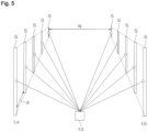
- FIG. 5 is a schematic perspective view illustrating a state where a laser light is emitted from the distance sensor 13 to the crop S included in a crop row.
- FIG. 6 is a schematic plan view of FIG. 5 seen from above.
- FIGs. 5 and 6 illustrate two adjacent crop rows La and Lb.
- a coordinate system in which a laser light output position at the distance sensor 13 is an origin O, a straight line passing through the origin O and parallel to the right-left direction of the work vehicle 1 is an X axis, and a straight line passing through the origin O and parallel to the front-rear direction of the work vehicle 1 is a Y axis is called a sensor coordinate system.
- the laser light is emitted from the distance sensor 13 in a different direction.
- a laser light emitting direction (emission angle) ⁇ is an angle between the +X axis and the laser light, and expressed as an angle counterclockwise around the origin O.
- the combination of the distance r and the emission angle ⁇ (r, ⁇ ) is acquired as distance information for the object.
- the X coordinate value x and the Y coordinate value y of the sensor coordinate system of the object whose distance information is (r, ⁇ ) are expressed by the following formula (1).
- the rectangle identification unit 41 first detects a position (x, y) of each object whose distance from the distance sensor 13 has been detected, on the basis of the aforementioned formula (1).
- the rectangle identification unit 41 detects a plurality of crop rows L on the basis of the position (x, y) of each object.
- the rectangle identification unit 41 selects, as a target crop row pair, for example, a crop row pair that is arranged in such a manner that two adjacent crop rows sandwich a straight line passing through the center of the work vehicle 1 and extending in the front-rear direction of the work vehicle 1.
- the rectangle identification unit 41 identifies the target crop row pair as a rectangle (rectangle or square) whose opposite sides are two crop rows constituting the target crop row pair. In other words, the rectangle identification unit 41 identifies a rectangle that approximates the target crop row pair.
- this process is called a rectangle identification process.
- one of the two adjacent sides of the rectangle is called a first side, and the other side is called a second side.
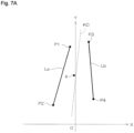
- the rectangle identification unit 41 first calculates a center of gravity g and a slope a of the target crop row pair. Specifically, the rectangle identification unit 41 acquires the coordinates of end points P1 and P2 of the crop row La and the coordinates of end points P3 and P4 of the crop row Lb. Then, the rectangle identification unit 41 calculates the center of gravity of a quadrangle having these four points as vertices as the center of gravity g of the target crop row pair.
- the slope a of the target crop row pair is, for example, the slope of a straight line K0 that passes through almost the center between the two crop rows La and Lb, and can be calculated by, for example, a least-squares method.
- the slope a of the target crop row pair thus calculated may be referred to as a "first slope a1".
- the rectangle identification unit 41 obtains a first straight line K1 passing through an end point (P4 in this example) having the largest X coordinate value among the end points P1 to P4 and having a first slope a1. Then, the rectangle identification unit 41 calculates the distance between the first straight line K1 and an end point (P2 in this example) having the smallest X coordinate value among the end points P1 to P4, as a length q1 of the first side.
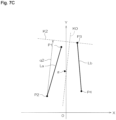
- the rectangle identification unit 41 obtains the slope of a straight line orthogonal to the straight line having the first slope a1 in the XY plane, as a second slope a2. Then, as illustrated in FIG. 7 , the rectangle identification unit 41 obtains a second straight line K2 passing through an end point (P3 in this example) having the largest Y coordinate value among the end points P1 to P4 and having the second slope a2. Then, the rectangle identification unit 41 calculates the distance between the second straight line K2 and an end point (P2 in this example) having the smallest Y coordinate value among the end points P1 to P4, as a length q2 of the second side.
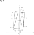
- the rectangle identification unit 41 identifies, as a rectangle that approximates the target crop row pair, a rectangle having the aforementioned center of gravity g as the center of gravity, the first side whose slope is the second slope a2 and whose length is q1, and the second side whose slope is the first slope a1 and whose length is q2.
- a rectangle that approximates this target crop row pair will be as illustrated by R in FIG. 7D .
- the rectangle identification unit 41 may obtain a rectangle that approximates the target crop row pair by a method other than the method described above.
- a method for obtaining the rectangle that approximates the target crop row pair for example, various methods described as background art and various methods described as embodiments of Japanese Unexamined Patent Application Publication No. 2010-108135 can be used.
- the target setting unit 42 sets the target travel route and the target direction of the work vehicle 1 between the two crop rows constituting the selected crop row pair, on the basis of the rectangle identified by the rectangle identification unit 41.
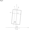
- the target setting unit 42 specifies the interval between the right and left sides of a rectangle R as a row interval W of the target crop row pair, as illustrated in FIG. 8 .
- the target setting unit 42 specifies the straight line that passes through the center of the right and left sides of the rectangle R, as a center line CL of the target crop row pair. Then, the target setting unit 42 sets, as a target travel route T, a straight line deviated to the side of one crop row (the left crop row La in the example of FIG. 8 ) by a predetermined offset amount ⁇ W, and at the same time sets a direction along the target travel route T as the target direction.
- the direction for deviating by the offset amount ⁇ W with respect to the center line CL differs depending on the target crop row pair. For example, when the first crop row L1 and the second crop row L2 in FIG. 3 are the target crop row pair, the direction for deviating by the offset amount ⁇ W with respect to the center line CL is the direction of the first crop row L1 side (left side toward the traveling direction). Meanwhile, when the second crop row L2 and the third crop row L3 in FIG. 3 are the target crop row pair, direction for deviating by the offset amount ⁇ W with respect to the center line CL is the direction of the second crop row L2 side (right side toward the traveling direction).
- the deviation calculation unit 43 calculates a deviation amount from the target travel route T and the deviation amount from the target direction.
- the deviation calculation unit 43 includes a position deviation calculation unit 43A and a direction deviation calculation unit 43B.
- the position deviation calculation unit 43A estimates the current position of the work vehicle 1 between the two crop rows constituting the target crop row pair on the basis of the rectangle R identified by the rectangle identification unit 41, and calculates a deviation amount (position deviation amount) of the current position from the target travel route.
- the direction deviation calculation unit 43B calculates a deviation amount (direction deviation amount) of the current direction of the work vehicle 1 detected by the direction sensor 14, from the target direction.
- the position deviation calculation unit 43A converts the position and direction of the work vehicle 1 in the sensor coordinate system, into the position and direction of the crop row coordinate system in which the target travel route T is a Y' axis and a line that is orthogonal to the Y' axis and passes through the center of gravity of the work vehicle 1 is an X' axis.
- the converted position and direction of the work vehicle 1 correspond to the current position and direction of the work vehicle 1 between the two crop rows constituting the target crop row pair.
- the position deviation calculation unit 43A sets, as a target position Q, a position that has advanced in the traveling direction by a predetermined distance f along the target travel route T from the origin O' of the crop row coordinate system. Then, the position deviation calculation unit 43A calculates an angle ⁇ between the straight line connecting the target position Q and the center of gravity position G of the work vehicle 1 and the Y' axis, as the position deviation amount (position deviation angle) of the work vehicle 1 with respect to the target travel route T. If the distance between the origin O' and the center of gravity position G of the work vehicle 1 is ⁇ x, the position deviation amount ⁇ can be calculated from the following formula (2).
- the direction deviation calculation unit 43B calculates an angle ⁇ formed by the orientation (front-rear direction) of the work vehicle 1 and the target direction (Y' axis) as the direction deviation amount.
- the direction deviation amount ⁇ can be calculated in the same manner as the position deviation amount ⁇ by obtaining a Y' coordinate value of the intersection of the Y' axis and a straight line passing through the center of gravity G of the work vehicle 1 and extending in the front-rear direction of the work vehicle 1
- the correction unit 44 includes a position correction unit 44A and a direction correction unit 44B.
- the position correction unit 46A corrects the position of the work vehicle 1 between the crop rows in such a manner that the position approaches the target travel route T, on the basis of the position deviation amount ⁇ calculated by the position deviation calculation unit 43A.
- the direction correction unit 44B corrects the direction of the work vehicle 1 between the crop rows in such a manner that the direction approaches the target direction, on the basis of the direction deviation amount ⁇ calculated by the direction deviation calculation unit 43B. That is, in this embodiment, the correction unit 44 controls the crawler control mechanism 15 in such a manner that the position deviation amount ⁇ approaches zero and the direction deviation amount ⁇ approaches zero.
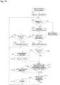
- FIG. 10 is a flowchart illustrating an overall procedure of an automatic travel control process by the automatic travel control unit 32.
- the operation modes of the work vehicle 1 include a search mode and a run mode.
- the search mode refers to a mode for setting the target travel route and target direction, and the like by performing a crop row identification process before entering between crop rows.
- the crop row identification process refers to a process performed by the rectangle identification unit 41, target setting unit 42, and deviation calculation unit 43 to set the target travel route T and target direction and calculate the row interval W, the position deviation amount ⁇ from the target travel route T, the direction deviation amount ⁇ from the target direction, and the like.
- the run mode is a mode in which the work vehicle 1 caused to travel in such a manner that the position deviation amount ⁇ and the direction deviation amount ⁇ approach zero while performing the crop row identification process.
- the user When performing an automatic travel control, the user sets the row interval W and a target number of turns N to the work vehicle 1.
- the target number of turns N is the number of turns of the work vehicle 1 expected to be performed before the work vehicle 1 reaches a position at which automatic operation should be stopped after it is started.
- the row interval W and the target number of turns N set by the user are stored in the memory 31.
- the user moves the work vehicle 1 to the vicinity of the start position of automatic travel by, for example, a remote control. Then, the user starts the automatic travel control by, for example, a remote control.
- the automatic travel control unit 32 sets the operation mode to a search mode (step S1). Then, the automatic travel control unit 32 determines if the number of turns of the work vehicle 1 has reached the target number of turns N.
- step S2 If the number of turns of the work vehicle 1 has not reached the target number of turns N (step S2: NO), the automatic travel control unit 32 performs the crop row identification process described above (step S3).
- the automatic travel control unit 32 determines whether the crop row detection is successful (step S4). Specifically, the automatic travel control unit 32 determines that the crop row detection is successful if a success or failure condition is fulfilled in which the position deviation amount ⁇ calculated by the crop row identification process is within a first predetermined range and the direction deviation amount ⁇ calculated by the crop row identification process is within a second predetermined range. On the other hand, if the target crop row pair is not specified by the crop row identification process, or if the target crop row pair is specified and the success or failure determination condition is not fulfilled, the automatic travel control unit 32 determines that the crop row detection has failed.
- step S4 determines whether the operation mode is the search mode (step S5). If the operation mode is the search mode (step S5: YES), the automatic travel control unit 32 changes the position of the work vehicle 1 and moves the work vehicle 1 again to perform the crop row identification process (step S6).
- the automatic travel control unit 32 may simply retract the work vehicle 1 by a predetermined amount when the target crop row pair is not specified in the crop row identification process of step S3. On the other hand, when the target crop row pair is specified in the crop row identification process of step S3, the automatic travel control unit 32 may move the work vehicle 1 to the center position side between the two crop rows constituting the target crop row pair. When the process of step S6 is completed, the automatic travel control unit 32 returns to step S2.
- step S5 if it is determined that the operation mode is the run mode (step S5: NO), the automatic travel control unit 32 returns to step S2.
- step S4 if it is determined that the crop row detection is successful (step S4: YES), the automatic travel control unit 32 updates the row interval W in the memory 31 (step S7). Specifically, the automatic travel control unit 32 rewrites the row interval W stored in the memory 31 to the row interval W acquired by the crop row identification process of step S3.
- the automatic travel control unit 32 determines whether the operation mode is the search mode (step S8). If the operation mode is the search mode (step S8: YES), the automatic travel control unit 32 sets a reference direction (step S9). Specifically, the automatic travel control unit 32 uses the direction deviation amount ⁇ calculated in step S3 and the direction of the work vehicle 1 currently detected by the direction sensor 14 to convert the target direction set in step S3 into the direction detected by the direction sensor 14. Then, the automatic travel control unit 32 stores the converted direction in the memory 31 as the reference direction. In this way, the difference between the direction of the work vehicle 1 detected by the direction sensor 14 and the reference direction can be detected as the direction deviation amount of the direction of the work vehicle 1 with respect to the target direction.
- the automatic travel control unit 32 sets the operation mode to the run mode (step S10). Then, the automatic travel control unit 32 proceeds to step S11. In the run mode, the correction unit 44 of the automatic travel control unit 32 controls the crawler control mechanism 15 in such a manner that the position deviation amount ⁇ and the direction deviation amount ⁇ approach zero.
- step S8 if it is determined that the operation mode is the run mode (step S8: NO), the automatic travel control unit 32 proceeds to step S11.
- step S11 the automatic travel control unit 32 determines whether the determination result of step S4 is that the crop row detection has succeeded at least a predetermined number of times in succession.
- step S4 determines whether the crop row detection has succeeded at least a predetermined number of times in succession. If the determination result in step S4 is that the crop row detection has succeeded at least a predetermined number of times in succession (step S11: YES), the automatic travel control unit 32 updates the reference direction (step S12). Specifically, the automatic travel control unit 32 uses the direction deviation amount ⁇ set in step S3 and the direction of the work vehicle 1 currently detected by the direction sensor 14 to convert the target direction set in step S3 into the direction detected by the direction sensor 14. Then, the automatic travel control unit 32 rewrites the reference direction stored in the memory 31 to the converted direction. After this, the automatic travel control unit 32 proceeds to step S13.
- step S11 if it is determined that the determination result of step S4 is not that the crop row detection has succeeded at least a predetermined number of times in succession (step S 11: NO), the automatic travel control unit 32 does not update the reference direction, and proceeds to step S13.
- the reference direction is updated only if the determination result of step S4 is that the crop row detection has succeeded at least a predetermined number of times in succession. This is to prevent the reference direction from being updated when the crop row identification process is not performed accurately due to the effect of noise or the like.
- step S13 the automatic travel control unit 32 determines whether the work vehicle 1 has reached the traveling termination end (row end) between the crop rows.
- the automatic travel control unit 32 starts to measure the traveling distance, for example, when the work vehicle 1 reaches a front position by a predetermined distance from the traveling termination end between the target crop row pair, and determines that the work vehicle 1 has reached the traveling termination end between the crop rows when the measured traveling distance reaches the aforementioned predetermined distance.
- the automatic travel control unit 32 may start measuring time when the work vehicle 1 reaches the front position by a predetermined distance from the traveling termination end between the target crop row pair, and may determine that the work vehicle 1 has reached the traveling termination end between the crop rows when a time required for the work vehicle 1 to travel the predetermined distance has elapsed.
- step S13 NO
- the automatic travel control unit 32 returns to step S2.
- step S13 if it is determined that the work vehicle 1 has reached the traveling termination end between the target crop row pair (step S13:YES), the automatic travel control unit 32 turns the work vehicle 1 in order to move the work vehicle 1 to the traveling start end between the next crop rows (step S14). Specifically, the automatic travel control unit 32 controls the crawler control mechanism 15 to turn the work vehicle 1 approximately 180 degrees in a predetermined turning direction. The turning radius is set to 1/2 of the row interval W stored in the memory 31.
- the predetermined turning direction is determined on the basis of the preset turning direction at the first traveling termination end and information on the number of turns as of the current turn. For example, when the turning direction at the first traveling termination end is to the right, if the current turn is an odd number, the turning direction is to the right, and if the current turn is an even number, the turning direction is to the left. On the other hand, when the turning direction at the first traveling termination end is to the left, if the current turn is an odd number the turning direction is to the left, and if the current turn is an even number, the turning direction is to the right.
- step S14 the automatic travel control unit 32 returns to step S2.
- step S2 when it is determined that the number of turns of the work vehicle 1 has reached the target number of turns N (step S2: YES), the automatic travel control unit 32 ends the automatic travel control.
- the automatic travel control unit 32 returns to step S2 after the turning in step S14, but may return to step S1 after the turning in step S14.
- the operation mode is set to the search mode, and thus the work vehicle is temporarily stopped.
- the adjacent crop rows L may not be straight but may be bent in the middle.
- the slopes of the adjacent crop rows L may change in the middle.
- the target direction (reference direction) is updated on the basis of the rectangle identified by the crop row identification process (see step S3) during automatic traveling, the target direction of the work vehicle 1 can be changed in accordance with the change in the slopes of the crop rows.
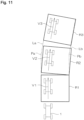
- the description will be given with the use of FIG. 11 .
- the two crop rows La and Lb constituting the target crop row pair are respectively bent to the right near intermediate positions Pa and Pb in the length direction.
- the work vehicle 1 is assumed to automatically travel between the crop rows La and Lb from the lower side to the upper side of the paper surface of FIG. 11 .
- the lower side end between the crop rows in FIG. 11 is the traveling start point and the upper side end between the crop rows is the traveling end point.
- the automatic travel control unit 32 identifies a first rectangle R1 corresponding to the portion from the traveling start point between the crop rows La and Lb to bending points Pa and Pb of the crop rows La and Lb.
- the slope (target direction) of both the right and left sides of the first rectangle R1 is an angle according to the average slope of the portion from the traveling start point in the crop rows La and Lb to the bending points Pa and Pb of the crop rows La and Lb. Therefore, the work vehicle 1 travels as indicated by an arrow V1.
- the automatic travel control unit 32 identifies a second rectangle R2 corresponding to the portion including the bending points Pa and Pb in the crop rows La and Lb in the middle in the length direction.
- the slope (target direction) of both the right and left sides of the second rectangle R2 is an angle according to the average slope of the portion including the bending points Pa and Pb in the crop rows La and Lb in the middle in the length direction. Therefore, the slope of the second rectangle R2 is an angle inclined to the right toward the traveling direction with respect to the slope of the first rectangle R1.
- the target direction reference direction
- the work vehicle 1 travels as indicated by an arrow V2.
- the automatic travel control unit 32 identifies a third rectangle R3 corresponding to a portion further to the traveling termination end side than the bending points Pa and Pb in the crop rows La and Lb.
- the slope (target direction) of both the right and left sides of the third rectangle R3 is an angle according to the average slope of the portion further to the traveling termination end side than the bending points Pa and Pb in the crop rows La and Lb. Therefore, the slope of the third rectangle R3 is an angle further inclined to the right toward the traveling direction with respect to the slope of the second rectangle R2.
- the target direction reference direction
- the work vehicle 1 travels as indicated by an arrow V3. In this way, the work vehicle 1 travels along the target travel route according to the shape of the crop rows La and Lb even when the crop rows La and Lb are bent in the middle.
- a rectangle whose opposite sides are adjacent crop rows is identified, and on the basis of the identified rectangle, the target travel route and the target direction are set, and at the same time the current position of the work vehicle is estimated. Therefore, for example, when the slopes of adjacent crop rows change in the middle, such as when the adjacent crop rows bend in the middle, a rectangle according to a slope near the work vehicle in the adjacent crop rows is identified. This makes it possible to set a target travel route between adjacent crop rows corresponding to changes in the slopes of these crop rows, and to estimate the position of the work vehicle 1 between both crop rows.
- the work vehicle 1 is moved to the automatic travel start position by remote control.
- the work vehicle 1 may be transported to the automatic travel start position by a truck or the like.
- the work vehicle 1 may be manually operated and may be moved to the automatic travel start position by the manual operation.
- the LIDAR is used as the distance sensor 13, but a distance sensor other than LIDAR such as a monocular camera or a stereo camera may be used.
- the work vehicle is a work vehicle for spraying a chemical liquid
- the work vehicle may be a work vehicle for other than spraying a chemical liquid.
Landscapes
- Engineering & Computer Science (AREA)
- Remote Sensing (AREA)
- Radar, Positioning & Navigation (AREA)
- Automation & Control Theory (AREA)
- Physics & Mathematics (AREA)
- General Physics & Mathematics (AREA)
- Life Sciences & Earth Sciences (AREA)
- Aviation & Aerospace Engineering (AREA)
- Mechanical Engineering (AREA)
- Soil Sciences (AREA)
- Environmental Sciences (AREA)
- Guiding Agricultural Machines (AREA)
- Control Of Position, Course, Altitude, Or Attitude Of Moving Bodies (AREA)
- Navigation (AREA)
- Traffic Control Systems (AREA)
Description
- This invention relates to a work vehicle and a deviation amount calculation program.
-
Patent Literature 1 discloses a work machine that travels along a furrow. InPatent Literature 1, an automatic travel control of the work machine is performed on the basis of the angle of the work machine to a ridge and a position deviation amount of the work machine from the center of the ridge. -
Patent Literature 2 discloses a harvester that performs an automatic travel control when the traveling direction of the machine approaches one side of the right and left crop rows. -
- Patent Literature 1:
Japanese Unexamined Patent Application Publication No. 2016-208871 - Patent Literature 2:
Japanese Unexamined Patent Application Publication No. Hei 11-275912 - Disclosed in
Patent Literature 1 is a technique directed to a field where there are ridges the edges of which can be detected relatively easily. For example, in the case of an orchard without ridges, a trunk is hidden by the leaves and branches of a crop, and thus it may not be possible to accurately detect a crop row. Therefore, it is difficult to apply the travel control such as that inPatent Literature 1 to a field without ridges. - In addition, in
Patent Literature 2, an image acquired by an imaging means is rotated, an amount of deviation of a work machine from the center position of a ridge is calculated on the basis of this rotated image, and an angle in the traveling direction of the work machine with respect to the ridge is calculated. This is a process on condition that ridges extend straight along the traveling direction of the work machine. Therefore, inPatent Literature 2, when the ridges do not extend straight, it is difficult to identify the position and angle (direction) of the work machine. - Even in
Patent Literature 2, the position and direction of the harvester when each crop row does not extend straight are not considered. - Documents
JP H01 206904 A US 2010/104194 A1 disclose a work vehicle configured to travel in a field where a plurality of crop rows are planted. The work vehicle comprises a distance sensor configured to acquire information on a distance from the work vehicle to each of a plurality of objects present in the field. - It is an object of the present invention to provide a work vehicle capable of identifying its own position between crop rows regardless of the condition of a field and a deviation amount calculation program capable of the same.
- A work vehicle according to the present invention is a work vehicle that is configured to travel in a field where a plurality of crop rows are planted, and that includes a distance sensor configured to acquire information on a distance from the work vehicle to each of a plurality of objects present in the field, a rectangle identification unit configured to estimate the plurality of crop rows on a basis of the distance information and identify a rectangle whose opposite sides are adjacent crop rows of the estimated crop rows, a target setting unit configured to set a target travel route of the work vehicle between the adjacent crop rows on a basis of the rectangle, and a position deviation calculation unit configured to estimate a current position of the work vehicle between the adjacent crop rows on a basis of the rectangle, and calculate a deviation amount of the current position from the target travel route.
- With this configuration, it is possible to achieve a work vehicle that can automatically set a target travel route of a work vehicle between adjacent crop rows and can acquire a deviation amount of the current position of the work vehicle from the target travel route.
- In addition, with this configuration, a rectangle whose opposite sides are adjacent crop rows is identified, and the target travel route is set on the basis of the identified rectangle, and at the same time the current position of the work vehicle is estimated. Therefore, for example, when the slopes of adjacent crop rows change in the middle, such as when the adjacent crop rows bend in the middle, a rectangle according to a slope near the work vehicle in the adjacent crop rows is identified. This makes it possible to set a target travel route between adjacent crop rows corresponding to changes in the slopes of these crop rows, and to estimate the position of the work vehicle between the adjacent crop rows. In other words, with this configuration, it is possible to identify the position of the work vehicle itself between the crop rows regardless of the condition of a field such as bending of the crop rows.
- One embodiment of the present invention further includes a position correction unit configured to correct a position of the work vehicle between the crop rows in such a manner that the position approaches the target travel route, on a basis of the deviation amount calculated by the position deviation calculation unit.
- With this configuration, the position of the work vehicle can be corrected so as to approach the target travel route, and thus the work vehicle can be caused to automatically travel along the target travel route.
- One embodiment of the present invention further includes a direction sensor configured to detect a direction of the work vehicle. The target setting unit is configured to also set a target direction of the work vehicle. The work vehicle further includes a direction deviation calculation unit configured to calculate a deviation amount of a current direction of the work vehicle detected by the direction sensor from the target direction.
- With this configuration, it is possible to acquire a deviation amount of the current direction of the work vehicle from the target direction.
- One embodiment of the present invention further includes a direction correction unit configured to correct a direction of the work vehicle between the crop rows in such a manner that the direction approaches the target direction, on a basis of the deviation amount calculated by the direction deviation calculation unit.
- With this configuration, it is possible to cause the work vehicle to automatically travel in such a manner that the direction of the work vehicle approaches the target direction.
- In one embodiment of the present invention, the rectangle identification unit repeatedly identifies the rectangle while the work vehicle travels between the crop rows, the target direction setting unit sets the target direction on a basis of the rectangle each time the rectangle is identified, and the direction deviation calculation unit calculates a deviation amount of a current direction of the work vehicle detected by the direction sensor from the target direction, each time the target direction is set.
- With this configuration, for example, when the slopes of adjacent crop rows change in the middle, such as when the adjacent crop rows bend in the middle, a rectangle according to a slope near the work vehicle in the adjacent crop rows is identified. This makes it possible to set a target direction corresponding to changes in the slopes of the adjacent crop rows, and to acquire a deviation amount of the current direction of the work vehicle from the target direction.
- A deviation amount calculation program according to the present invention is a deviation amount calculation program that sets a target travel route of a work vehicle in a field where a plurality of crop rows are planted and calculates a deviation amount of the work vehicle from the target travel route. The deviation amount calculation program causes a computer to function as a rectangle identification unit for estimating the plurality of crop rows on a basis of information on a distance from the work vehicle to each of a plurality of objects present in the field and identifying a rectangle whose opposite sides are adjacent crop rows of the estimated crop rows, a target setting unit for setting a target travel route of the work vehicle, between the adjacent crop rows, on a basis of the rectangle, and a position deviation calculation unit for estimating a current position between the adjacent crop rows on a basis of the rectangle and calculate a deviation amount of the current position from the target travel route.
- With this deviation amount calculation program, it is possible to automatically set a target travel route of a work vehicle between adjacent crop rows and to acquire a deviation amount of the current position of the work vehicle from the target travel route.
- In addition, with this deviation amount calculation program, a rectangle whose opposite sides are adjacent crop rows is identified, and the target travel route is set on the basis of the identified rectangle, and at the same time the current position of the work vehicle is estimated. Therefore, for example, when the slopes of adjacent crop rows change in the middle, such as when the adjacent crop rows bend in the middle, a rectangle according to a slope near the work vehicle in the adjacent crop rows is identified. This makes it possible to set a target travel route between adjacent crop rows corresponding to changes in the slopes of these crop rows, and to estimate the position of the work vehicle between the adjacent crop rows. In other words, with this configuration, it is possible to identify its own position of the work vehicle between the crop rows regardless of the condition of a field such as bending of the crop rows.
- The above and/or other objects, features and effects of the present invention will be made clear by the description of the embodiment below with reference to the accompanying drawings.
-
-
FIG. 1 is a side view illustrating a schematic configuration of a work vehicle according to an embodiment of the present invention. -
FIG. 2 is a front view illustrating a schematic configuration of the work vehicle ofFIG. 1 . -
FIG. 3 is a schematic diagram illustrating how the work vehicle automatically travels in a field. -
FIG. 4 is a block diagram illustrating a main electrical configuration of the work vehicle. -
FIG. 5 is a schematic perspective view illustrating a state where a laser light is emitted from a distance sensor to a crop included in a crop row. -
FIG. 6 is a schematic plan view ofFIG. 5 seen from above. -
FIG. 7A is a schematic diagram for explaining a procedure of a rectangle identification process. -
FIG. 7B is a schematic diagram for explaining the next procedure ofFIG. 7A . -
FIG. 7C is a schematic diagram for explaining the next procedure ofFIG. 7B . -
FIG. 7D is a schematic diagram for explaining the next procedure ofFIG. 7C . -
FIG. 8 is a schematic diagram for explaining the operation of a target setting unit. -
FIG. 9 is a schematic diagram for explaining the operation of a deviation calculation unit. -
FIG. 10 is a flowchart illustrating an overall procedure of an automatic travel control process by an automatic travel control unit. -
FIG. 11 is a schematic diagram for explaining that a target direction can be corrected in accordance with a change in the slope of a crop row even when the slopes of adjacent crop rows change in the middle. -
FIG. 1 is a side view illustrating a schematic configuration of a work vehicle according to an embodiment of the present invention.FIG. 2 is a front view illustrating a schematic configuration of the work vehicle ofFIG. 1 . - A
work vehicle 1 is, in this embodiment, a work vehicle for spraying a chemical liquid. Thework vehicle 1 includes a travelingdevice 2, amachine body frame 3 supported on the travelingdevice 2, and a chemicalliquid spraying device 4 provided on themachine body frame 3. In this embodiment, the travelingdevice 2 is a crawler type, and includes right and left travelingdevices device 2 may be a wheel type. Hereinafter, the schematic representation of a vehicle including a wheel type traveling device may be used as a schematic representation of thework vehicle 1. - An
engine 5 as a drive source is disposed at the rear of themachine body frame 3. Asupport frame 6 is provided at the front of themachine body frame 3. Thesupport frame 6 includes a pair of right andleft masts machine body frame 3, afirst coupling member 6C that couples the upper ends of thesemasts second coupling member 6D that couples a length intermediate portions of thesemasts - The chemical
liquid spraying device 4 includes achemical liquid tank 7, anozzle unit 8, and apump unit 9. Thechemical liquid tank 7 is disposed in the front-rear central portion on themachine body frame 3. Thechemical liquid tank 7 stores a chemical liquid. The chemical liquid may be any liquid that is sprayed on crops or soil, and includes a pesticide, water, and the like. Thenozzle unit 8 is attached to a position near the upper end of thesupport frame 6. Thenozzle unit 8 is a hollow body that extends in the right-left direction and includesnozzles nozzle unit 8 is formed with a chemical liquid inlet (not illustrated). - Although the
pump unit 9 is not illustrated inFIGs. 1 and2 , in this embodiment, apump 9A (seeFIG. 4 ) which is rotationally driven by the power of theengine 5, aclutch mechanism 9B that transmits or shuts off the rotational force of theengine 5 to thepump 9A (seeFIG. 4 ), and the like are included. The suction port of thepump 9A is connected to thechemical liquid tank 7 via ahose 10. The discharge port of thepump 9A is connected to the chemical liquid inlet of thenozzle unit 8 via ahose 11. When thepump 9A is rotationally driven, the chemical liquid in thechemical liquid tank 7 is supplied to thenozzle unit 8 via thepump 9A, and the chemical liquid is spouted from thenozzles - The
work vehicle 1 is equipped with adistance sensor 13 for measuring a distance to an object and a direction sensor (posture sensor) 14 (seeFIG. 4 ) for detecting a direction (posture) of thework vehicle 1. Thedistance sensor 13 is disposed at a width center position of the front of thework vehicle 1. - The
distance sensor 13 may be any sensor that can measure a distance to an object, and for example, a sensor that measures a distance to an object with the use of laser light, a sensor that measures a distance to an object with the use of a camera, or the like may be used. In this embodiment, as thedistance sensor 13, for example, a light, detection and ranging, or laser imaging detection and ranging (LIDAR) that measures a distance from a time it takes for a laser light to be illuminated in a pulse form and to be reflected by an object and return is used. In particular, in this embodiment, as thedistance sensor 13, a scan sensor LIDAR is used that can detect the direction of an object by scanning a laser light by changing its direction with a movable mirror. - A gyro sensor, a geomagnetic sensor, an inertial measurement unit (IMU), or the like can be used as the direction sensor (posture sensor) 14.
- Although not illustrated in
FIGs. 1 and2 , thework vehicle 1 is provided with a crawler control mechanism 15 (seeFIG. 4 ) that transmits the driving force of theengine 5 to the right and left travelingdevices devices crawler control mechanism 15 is a mechanism for driving the right and left travelingdevices work vehicle 1 forward, backward, and turn. Specifically, when the right and left travelingdevices crawler control mechanism 15, thework vehicle 1 moves forward or backward. Meanwhile, when the right and left travelingdevices devices crawler control mechanism 15, thework vehicle 1 turns. - In this embodiment, as illustrated in
FIG. 3 , thework vehicle 1 automatically travels in a field H where a crop S is planted in a row and sprays a chemical liquid on the crop S. In this embodiment, the crop S is a fruit tree and the field H is an orchard. In this description, the row of the crop S is referred to as a crop row L. In the example ofFIG. 3 , the row of the crop S arranged vertically is the crop row L. In the field H, five crop rows L1 to L5 are laterally planted at intervals. In each crop row L1 to L5, a plurality of crops S are arranged at substantially equal intervals. These crop rows L1 to L5 are referred to as a first crop row L1, a second crop row L2, a third crop row L3, a fourth crop row L4, and a fifth crop row L5 in order from the left. In addition, of the spaces between adjacent crop rows, the lower side end ofFIG. 3 is called a front side end, and the upper side end ofFIG. 3 is called a back side end. - For example, the
work vehicle 1 automatically travels between crop rows toward the back side end while using, for example, a vicinity of the front side end between the first crop row L1 and the second crop row L2, as an automatic travel start position and setting a target travel route between these crop rows. When thework vehicle 1 reaches the back side end between the crop rows, thework vehicle 1 turns to the right in the traveling direction, and moves to the back side end between the second crop row L2 and the third crop row L3. Then, thework vehicle 1 automatically travels between crop rows toward the front side end while setting the target travel route between the second crop row L2 and the third crop row L3. - When the
work vehicle 1 reaches the front side end between the crop rows L2 and L3, thework vehicle 1 turns to the left toward the traveling direction and moves to the front side end between the third crop row L3 and the fourth crop row L4. Then, thework vehicle 1 automatically travels between crop rows toward the back side end while setting the target travel route between the third crop row L3 and the fourth crop row L4. By the same operation, thework vehicle 1 moves as illustrated by the broken line inFIG. 3 . Then, for example, after thework vehicle 1 reaches the front side end between the fourth crop row L4 and the fifth crop row L5 and turns to the left toward the traveling direction, the automatic traveling is stopped. During automatic traveling, thepump 9A is driven via theclutch mechanism 9B, and the chemical liquid is ejected from thenozzles - In the following, between certain adjacent crop rows, of the front side end and the back side end between the crop rows, the end on the side where the
work vehicle 1 starts traveling may be referred to as a traveling start end between the crop rows, and the end on the side opposite to the traveling start end may be called a traveling termination end between the crop rows. In addition, an interval W between adjacent crop rows may be called a row interval. - It is possible for a user or the like to remotely control the
work vehicle 1 by operating a remote control device (not illustrated), but such remote control technique is well known. Thus, the description of the specific configuration for performing a remote control is omitted. -
FIG. 4 is a block diagram illustrating a main electrical configuration of thework vehicle 1. - The
work vehicle 1 includes acontrol device 30 for controlling the operation of thework vehicle 1. - Connected to the
control device 30 are thedistance sensor 13, adirection sensor 14, anengine controller 21, atravel controller 22, aclutch actuator 23, astorage unit 24, and the like. - As described above, the
distance sensor 13 detects information on a distance from the work vehicle to each of a plurality of objects present in the field H. The main target of the plurality of objects is the crop S. Thedirection sensor 14 is, as described above, for detecting the direction of thework vehicle 1. - The
engine controller 21 controls the number of revolutions of theengine 5, or the like. Specifically, theengine controller 21 controls acommon rail device 16 as a fuel injection device provided in theengine 5, thereby controlling the number of revolutions of theengine 5. Theengine controller 21 controls thecommon rail device 16, and thereby can also stop the supply of fuel to theengine 5 and stop the drive of theengine 5. - The
travel controller 22 controls forward, backward, turning, and stopping of thework vehicle 1 by controlling thecrawler control mechanism 15. Theclutch actuator 23 is for fastening and releasing theclutch mechanism 9B in thepump unit 9. Thestorage unit 24 includes a storage device such as a hard disk and a non-volatile memory. - The
control device 30 includes a microcomputer including a central processing unit (CPU) and a memory (read-only memory, or ROM, random-access memory, or RAM, etc.) 31. Thecontrol device 30 includes an automatictravel control unit 32 for causing thework vehicle 1 to automatically travel along a target travel route while setting the target travel route between adjacent crop rows L in the field H. The automatictravel control unit 32 includes arectangle identification unit 41, atarget setting unit 42, adeviation calculation unit 43, and acorrection unit 44. - The
rectangle identification unit 41 estimates the plurality of crop rows on the basis of information on a distance from thework vehicle 1 to each of a plurality of objects present in the field H and identifies a rectangle whose opposite sides are adjacent crop rows of the estimated crop rows. The information on the distance from thework vehicle 1 to each of the plurality of objects present in the field H is the distance information to each object detected by thedistance sensor 13. The operation of therectangle identification unit 41 will be described in detail below. -
FIG. 5 is a schematic perspective view illustrating a state where a laser light is emitted from thedistance sensor 13 to the crop S included in a crop row.FIG. 6 is a schematic plan view ofFIG. 5 seen from above.FIGs. 5 and6 illustrate two adjacent crop rows La and Lb. - Referring to
FIG. 6 , a coordinate system in which a laser light output position at thedistance sensor 13 is an origin O, a straight line passing through the origin O and parallel to the right-left direction of thework vehicle 1 is an X axis, and a straight line passing through the origin O and parallel to the front-rear direction of thework vehicle 1 is a Y axis is called a sensor coordinate system. - The laser light is emitted from the
distance sensor 13 in a different direction. A laser light emitting direction (emission angle) θ is an angle between the +X axis and the laser light, and expressed as an angle counterclockwise around the origin O. When the laser light is output at the emission angle θ and a distance r to a certain object is detected, the combination of the distance r and the emission angle θ (r, θ) is acquired as distance information for the object. The X coordinate value x and the Y coordinate value y of the sensor coordinate system of the object whose distance information is (r, θ) are expressed by the following formula (1).

rectangle identification unit 41 first detects a position (x, y) of each object whose distance from thedistance sensor 13 has been detected, on the basis of the aforementioned formula (1). - Next, the
rectangle identification unit 41 detects a plurality of crop rows L on the basis of the position (x, y) of each object. - Next, the
rectangle identification unit 41 selects, as a target crop row pair, for example, a crop row pair that is arranged in such a manner that two adjacent crop rows sandwich a straight line passing through the center of thework vehicle 1 and extending in the front-rear direction of thework vehicle 1. - Next, the
rectangle identification unit 41 identifies the target crop row pair as a rectangle (rectangle or square) whose opposite sides are two crop rows constituting the target crop row pair. In other words, therectangle identification unit 41 identifies a rectangle that approximates the target crop row pair. Hereinafter, this process is called a rectangle identification process. In the following, one of the two adjacent sides of the rectangle is called a first side, and the other side is called a second side. - An example of the rectangle identification process will be described below with reference to
FIGs. 7A to 7D . - For example, two crop rows La and Lb are selected as the target crop row pair as illustrated in
FIG. 7A . Therectangle identification unit 41 first calculates a center of gravity g and a slope a of the target crop row pair. Specifically, therectangle identification unit 41 acquires the coordinates of end points P1 and P2 of the crop row La and the coordinates of end points P3 and P4 of the crop row Lb. Then, therectangle identification unit 41 calculates the center of gravity of a quadrangle having these four points as vertices as the center of gravity g of the target crop row pair. The slope a of the target crop row pair is, for example, the slope of a straight line K0 that passes through almost the center between the two crop rows La and Lb, and can be calculated by, for example, a least-squares method. In the following, the slope a of the target crop row pair thus calculated may be referred to as a "first slope a1". - Next, as illustrated in
FIG. 7B , therectangle identification unit 41 obtains a first straight line K1 passing through an end point (P4 in this example) having the largest X coordinate value among the end points P1 to P4 and having a first slope a1. Then, therectangle identification unit 41 calculates the distance between the first straight line K1 and an end point (P2 in this example) having the smallest X coordinate value among the end points P1 to P4, as a length q1 of the first side. - Next, the
rectangle identification unit 41 obtains the slope of a straight line orthogonal to the straight line having the first slope a1 in the XY plane, as a second slope a2. Then, as illustrated inFIG. 7 , therectangle identification unit 41 obtains a second straight line K2 passing through an end point (P3 in this example) having the largest Y coordinate value among the end points P1 to P4 and having the second slope a2. Then, therectangle identification unit 41 calculates the distance between the second straight line K2 and an end point (P2 in this example) having the smallest Y coordinate value among the end points P1 to P4, as a length q2 of the second side. - Finally, the
rectangle identification unit 41 identifies, as a rectangle that approximates the target crop row pair, a rectangle having the aforementioned center of gravity g as the center of gravity, the first side whose slope is the second slope a2 and whose length is q1, and the second side whose slope is the first slope a1 and whose length is q2. In the case of the target crop row pair inFIG. 7A , a rectangle that approximates this target crop row pair will be as illustrated by R inFIG. 7D . - The
rectangle identification unit 41 may obtain a rectangle that approximates the target crop row pair by a method other than the method described above. As a method for obtaining the rectangle that approximates the target crop row pair, for example, various methods described as background art and various methods described as embodiments ofJapanese Unexamined Patent Application Publication No. 2010-108135 - Referring back to
FIG. 4 , thetarget setting unit 42 sets the target travel route and the target direction of thework vehicle 1 between the two crop rows constituting the selected crop row pair, on the basis of the rectangle identified by therectangle identification unit 41. - Specifically, the
target setting unit 42 specifies the interval between the right and left sides of a rectangle R as a row interval W of the target crop row pair, as illustrated inFIG. 8 . In addition, thetarget setting unit 42 specifies the straight line that passes through the center of the right and left sides of the rectangle R, as a center line CL of the target crop row pair. Then, thetarget setting unit 42 sets, as a target travel route T, a straight line deviated to the side of one crop row (the left crop row La in the example ofFIG. 8 ) by a predetermined offset amount ΔW, and at the same time sets a direction along the target travel route T as the target direction. - The direction for deviating by the offset amount ΔW with respect to the center line CL differs depending on the target crop row pair. For example, when the first crop row L1 and the second crop row L2 in
FIG. 3 are the target crop row pair, the direction for deviating by the offset amount ΔW with respect to the center line CL is the direction of the first crop row L1 side (left side toward the traveling direction). Meanwhile, when the second crop row L2 and the third crop row L3 inFIG. 3 are the target crop row pair, direction for deviating by the offset amount ΔW with respect to the center line CL is the direction of the second crop row L2 side (right side toward the traveling direction). - Referring back to
FIG. 4 , thedeviation calculation unit 43 calculates a deviation amount from the target travel route T and the deviation amount from the target direction. Thedeviation calculation unit 43 includes a positiondeviation calculation unit 43A and a directiondeviation calculation unit 43B. The positiondeviation calculation unit 43A estimates the current position of thework vehicle 1 between the two crop rows constituting the target crop row pair on the basis of the rectangle R identified by therectangle identification unit 41, and calculates a deviation amount (position deviation amount) of the current position from the target travel route. The directiondeviation calculation unit 43B calculates a deviation amount (direction deviation amount) of the current direction of thework vehicle 1 detected by thedirection sensor 14, from the target direction. - Specifically, as illustrated in
FIG. 9 , the positiondeviation calculation unit 43A converts the position and direction of thework vehicle 1 in the sensor coordinate system, into the position and direction of the crop row coordinate system in which the target travel route T is a Y' axis and a line that is orthogonal to the Y' axis and passes through the center of gravity of thework vehicle 1 is an X' axis. The converted position and direction of thework vehicle 1 correspond to the current position and direction of thework vehicle 1 between the two crop rows constituting the target crop row pair. - Next, as illustrated in
FIG. 9 , the positiondeviation calculation unit 43A sets, as a target position Q, a position that has advanced in the traveling direction by a predetermined distance f along the target travel route T from the origin O' of the crop row coordinate system. Then, the positiondeviation calculation unit 43A calculates an angle η between the straight line connecting the target position Q and the center of gravity position G of thework vehicle 1 and the Y' axis, as the position deviation amount (position deviation angle) of thework vehicle 1 with respect to the target travel route T. If the distance between the origin O' and the center of gravity position G of thework vehicle 1 is Δx, the position deviation amount η can be calculated from the following formula (2).
deviation calculation unit 43B calculates an angle δ formed by the orientation (front-rear direction) of thework vehicle 1 and the target direction (Y' axis) as the direction deviation amount. The direction deviation amount δ can be calculated in the same manner as the position deviation amount η by obtaining a Y' coordinate value of the intersection of the Y' axis and a straight line passing through the center of gravity G of thework vehicle 1 and extending in the front-rear direction of thework vehicle 1 - Referring back to
FIG. 4 , thecorrection unit 44 includes a position correction unit 44A and adirection correction unit 44B. The position correction unit 46A corrects the position of thework vehicle 1 between the crop rows in such a manner that the position approaches the target travel route T, on the basis of the position deviation amount η calculated by the positiondeviation calculation unit 43A. Thedirection correction unit 44B corrects the direction of thework vehicle 1 between the crop rows in such a manner that the direction approaches the target direction, on the basis of the direction deviation amount δ calculated by the directiondeviation calculation unit 43B. That is, in this embodiment, thecorrection unit 44 controls thecrawler control mechanism 15 in such a manner that the position deviation amount η approaches zero and the direction deviation amount δ approaches zero. -
FIG. 10 is a flowchart illustrating an overall procedure of an automatic travel control process by the automatictravel control unit 32. - The operation modes of the
work vehicle 1 include a search mode and a run mode. The search mode refers to a mode for setting the target travel route and target direction, and the like by performing a crop row identification process before entering between crop rows. The crop row identification process refers to a process performed by therectangle identification unit 41,target setting unit 42, anddeviation calculation unit 43 to set the target travel route T and target direction and calculate the row interval W, the position deviation amount η from the target travel route T, the direction deviation amount δ from the target direction, and the like. - The run mode is a mode in which the
work vehicle 1 caused to travel in such a manner that the position deviation amount η and the direction deviation amount δ approach zero while performing the crop row identification process. - When performing an automatic travel control, the user sets the row interval W and a target number of turns N to the
work vehicle 1. The target number of turns N is the number of turns of thework vehicle 1 expected to be performed before thework vehicle 1 reaches a position at which automatic operation should be stopped after it is started. The row interval W and the target number of turns N set by the user are stored in thememory 31. In addition, the user moves thework vehicle 1 to the vicinity of the start position of automatic travel by, for example, a remote control. Then, the user starts the automatic travel control by, for example, a remote control. - When the automatic travel control is started, the automatic
travel control unit 32 sets the operation mode to a search mode (step S1). Then, the automatictravel control unit 32 determines if the number of turns of thework vehicle 1 has reached the target number of turns N. - If the number of turns of the
work vehicle 1 has not reached the target number of turns N (step S2: NO), the automatictravel control unit 32 performs the crop row identification process described above (step S3). - Next, the automatic
travel control unit 32 determines whether the crop row detection is successful (step S4). Specifically, the automatictravel control unit 32 determines that the crop row detection is successful if a success or failure condition is fulfilled in which the position deviation amount η calculated by the crop row identification process is within a first predetermined range and the direction deviation amount δ calculated by the crop row identification process is within a second predetermined range. On the other hand, if the target crop row pair is not specified by the crop row identification process, or if the target crop row pair is specified and the success or failure determination condition is not fulfilled, the automatictravel control unit 32 determines that the crop row detection has failed. - When it is determined that the crop row detection has failed (step S4: NO), the automatic
travel control unit 32 determines whether the operation mode is the search mode (step S5). If the operation mode is the search mode (step S5: YES), the automatictravel control unit 32 changes the position of thework vehicle 1 and moves thework vehicle 1 again to perform the crop row identification process (step S6). - Specifically, the automatic
travel control unit 32 may simply retract thework vehicle 1 by a predetermined amount when the target crop row pair is not specified in the crop row identification process of step S3. On the other hand, when the target crop row pair is specified in the crop row identification process of step S3, the automatictravel control unit 32 may move thework vehicle 1 to the center position side between the two crop rows constituting the target crop row pair. When the process of step S6 is completed, the automatictravel control unit 32 returns to step S2. - In step S5, if it is determined that the operation mode is the run mode (step S5: NO), the automatic
travel control unit 32 returns to step S2. - In step S4, if it is determined that the crop row detection is successful (step S4: YES), the automatic
travel control unit 32 updates the row interval W in the memory 31 (step S7). Specifically, the automatictravel control unit 32 rewrites the row interval W stored in thememory 31 to the row interval W acquired by the crop row identification process of step S3. - Next, the automatic
travel control unit 32 determines whether the operation mode is the search mode (step S8). If the operation mode is the search mode (step S8: YES), the automatictravel control unit 32 sets a reference direction (step S9). Specifically, the automatictravel control unit 32 uses the direction deviation amount δ calculated in step S3 and the direction of thework vehicle 1 currently detected by thedirection sensor 14 to convert the target direction set in step S3 into the direction detected by thedirection sensor 14. Then, the automatictravel control unit 32 stores the converted direction in thememory 31 as the reference direction. In this way, the difference between the direction of thework vehicle 1 detected by thedirection sensor 14 and the reference direction can be detected as the direction deviation amount of the direction of thework vehicle 1 with respect to the target direction. - Next, the automatic
travel control unit 32 sets the operation mode to the run mode (step S10). Then, the automatictravel control unit 32 proceeds to step S11. In the run mode, thecorrection unit 44 of the automatictravel control unit 32 controls thecrawler control mechanism 15 in such a manner that the position deviation amount η and the direction deviation amount δ approach zero. - In step S8, if it is determined that the operation mode is the run mode (step S8: NO), the automatic
travel control unit 32 proceeds to step S11. In step S11, the automatictravel control unit 32 determines whether the determination result of step S4 is that the crop row detection has succeeded at least a predetermined number of times in succession. - If the determination result in step S4 is that the crop row detection has succeeded at least a predetermined number of times in succession (step S11: YES), the automatic
travel control unit 32 updates the reference direction (step S12). Specifically, the automatictravel control unit 32 uses the direction deviation amount δ set in step S3 and the direction of thework vehicle 1 currently detected by thedirection sensor 14 to convert the target direction set in step S3 into the direction detected by thedirection sensor 14. Then, the automatictravel control unit 32 rewrites the reference direction stored in thememory 31 to the converted direction. After this, the automatictravel control unit 32 proceeds to step S13. - In step S11, if it is determined that the determination result of step S4 is not that the crop row detection has succeeded at least a predetermined number of times in succession (step S 11: NO), the automatic
travel control unit 32 does not update the reference direction, and proceeds to step S13. The reference direction is updated only if the determination result of step S4 is that the crop row detection has succeeded at least a predetermined number of times in succession. This is to prevent the reference direction from being updated when the crop row identification process is not performed accurately due to the effect of noise or the like. - In step S13, the automatic
travel control unit 32 determines whether thework vehicle 1 has reached the traveling termination end (row end) between the crop rows. The automatictravel control unit 32 starts to measure the traveling distance, for example, when thework vehicle 1 reaches a front position by a predetermined distance from the traveling termination end between the target crop row pair, and determines that thework vehicle 1 has reached the traveling termination end between the crop rows when the measured traveling distance reaches the aforementioned predetermined distance. The automatictravel control unit 32 may start measuring time when thework vehicle 1 reaches the front position by a predetermined distance from the traveling termination end between the target crop row pair, and may determine that thework vehicle 1 has reached the traveling termination end between the crop rows when a time required for thework vehicle 1 to travel the predetermined distance has elapsed. - If the
work vehicle 1 has not reached the traveling termination end between the target crop row pair (step S13: NO), the automatictravel control unit 32 returns to step S2. - In step S13, if it is determined that the
work vehicle 1 has reached the traveling termination end between the target crop row pair (step S13:YES), the automatictravel control unit 32 turns thework vehicle 1 in order to move thework vehicle 1 to the traveling start end between the next crop rows (step S14). Specifically, the automatictravel control unit 32 controls thecrawler control mechanism 15 to turn thework vehicle 1 approximately 180 degrees in a predetermined turning direction. The turning radius is set to 1/2 of the row interval W stored in thememory 31. - The predetermined turning direction is determined on the basis of the preset turning direction at the first traveling termination end and information on the number of turns as of the current turn. For example, when the turning direction at the first traveling termination end is to the right, if the current turn is an odd number, the turning direction is to the right, and if the current turn is an even number, the turning direction is to the left. On the other hand, when the turning direction at the first traveling termination end is to the left, if the current turn is an odd number the turning direction is to the left, and if the current turn is an even number, the turning direction is to the right.
- When the process of step S14 is completed, the automatic
travel control unit 32 returns to step S2. - In step S2, when it is determined that the number of turns of the
work vehicle 1 has reached the target number of turns N (step S2: YES), the automatictravel control unit 32 ends the automatic travel control. - In the flowchart of
FIG. 10 , the automatictravel control unit 32 returns to step S2 after the turning in step S14, but may return to step S1 after the turning in step S14. In this case, after the turning in step S14, the operation mode is set to the search mode, and thus the work vehicle is temporarily stopped. - Depending on the field H, the adjacent crop rows L may not be straight but may be bent in the middle. In other words, the slopes of the adjacent crop rows L may change in the middle. In such a case, it is necessary to change the direction (target direction) of the target travel route of the
work vehicle 1 in accordance with the change in the slopes of the adjacent crop rows L. In the aforementioned embodiment, since the target direction (reference direction) is updated on the basis of the rectangle identified by the crop row identification process (see step S3) during automatic traveling, the target direction of thework vehicle 1 can be changed in accordance with the change in the slopes of the crop rows. In this respect, the description will be given with the use ofFIG. 11 . - In
FIG. 11 , the two crop rows La and Lb constituting the target crop row pair are respectively bent to the right near intermediate positions Pa and Pb in the length direction. Thework vehicle 1 is assumed to automatically travel between the crop rows La and Lb from the lower side to the upper side of the paper surface ofFIG. 11 . For convenience of explanation, it is assumed that the lower side end between the crop rows inFIG. 11 is the traveling start point and the upper side end between the crop rows is the traveling end point. - First, the automatic
travel control unit 32 identifies a first rectangle R1 corresponding to the portion from the traveling start point between the crop rows La and Lb to bending points Pa and Pb of the crop rows La and Lb. The slope (target direction) of both the right and left sides of the first rectangle R1 is an angle according to the average slope of the portion from the traveling start point in the crop rows La and Lb to the bending points Pa and Pb of the crop rows La and Lb. Therefore, thework vehicle 1 travels as indicated by an arrow V1. - When the
work vehicle 1 approaches the bending points Pa and Pb of the crop rows La and Lb, the automatictravel control unit 32 identifies a second rectangle R2 corresponding to the portion including the bending points Pa and Pb in the crop rows La and Lb in the middle in the length direction. The slope (target direction) of both the right and left sides of the second rectangle R2 is an angle according to the average slope of the portion including the bending points Pa and Pb in the crop rows La and Lb in the middle in the length direction. Therefore, the slope of the second rectangle R2 is an angle inclined to the right toward the traveling direction with respect to the slope of the first rectangle R1. As a result, the target direction (reference direction) is corrected to the right side toward the traveling direction. Therefore, thework vehicle 1 travels as indicated by an arrow V2. - When the
work vehicle 1 passes through the bending points Pa and Pb of the crop rows La and Lb, the automatictravel control unit 32 identifies a third rectangle R3 corresponding to a portion further to the traveling termination end side than the bending points Pa and Pb in the crop rows La and Lb. The slope (target direction) of both the right and left sides of the third rectangle R3 is an angle according to the average slope of the portion further to the traveling termination end side than the bending points Pa and Pb in the crop rows La and Lb. Therefore, the slope of the third rectangle R3 is an angle further inclined to the right toward the traveling direction with respect to the slope of the second rectangle R2. As a result, the target direction (reference direction) is corrected to the right side toward the traveling direction. Therefore, thework vehicle 1 travels as indicated by an arrow V3. In this way, thework vehicle 1 travels along the target travel route according to the shape of the crop rows La and Lb even when the crop rows La and Lb are bent in the middle. - That is, in the aforementioned embodiment, a rectangle whose opposite sides are adjacent crop rows is identified, and on the basis of the identified rectangle, the target travel route and the target direction are set, and at the same time the current position of the work vehicle is estimated. Therefore, for example, when the slopes of adjacent crop rows change in the middle, such as when the adjacent crop rows bend in the middle, a rectangle according to a slope near the work vehicle in the adjacent crop rows is identified. This makes it possible to set a target travel route between adjacent crop rows corresponding to changes in the slopes of these crop rows, and to estimate the position of the
work vehicle 1 between both crop rows. - While the embodiment of the present invention has been described above, the present invention can be implemented in other forms. For example, in the aforementioned embodiment, the
work vehicle 1 is moved to the automatic travel start position by remote control. However, thework vehicle 1 may be transported to the automatic travel start position by a truck or the like. In addition, thework vehicle 1 may be manually operated and may be moved to the automatic travel start position by the manual operation. - In addition, in the aforementioned embodiment, the LIDAR is used as the
distance sensor 13, but a distance sensor other than LIDAR such as a monocular camera or a stereo camera may be used. - Furthermore, in the aforementioned embodiment, the case where the work vehicle is a work vehicle for spraying a chemical liquid has been described, but the work vehicle may be a work vehicle for other than spraying a chemical liquid.
- While the embodiment of the present invention has been described in detail, that is merely a specific example used for clarifying the technical content of the present invention, and the present invention should not be construed as limited to the specific example, but the scope of the invention is limited only by the appended claims.
-
- 1 work vehicle
- 13 distance sensor
- 14 direction sensor
- 15 crawler control mechanism
- 16 common rail device
- 21 engine controller
- 22 travel controller
- 30 control device
- 31 memory
- 32 automatic travel control unit
- 41 rectangle identification unit
- 42 target setting unit
- 43 deviation calculation unit
- 43A position deviation calculation unit
- 43B direction deviation calculation unit
- 44 correction unit
- 44A position correction unit
- 44B direction correction unit
Claims (6)
- A work vehicle configured to travel in a field where a plurality of crop rows are planted, the work vehicle comprising:a distance sensor configured to acquire information on a distance from the work vehicle to each of a plurality of objects present in the field;characterised bya rectangle identification unit configured to estimate the plurality of crop rows on a basis of the distance information and identify a rectangle whose opposite sides are adjacent crop rows of the estimated crop rows;a target setting unit configured to set a target travel route of the work vehicle between the adjacent crop rows on a basis of the rectangle; anda position deviation calculation unit configured to estimate a current position of the work vehicle between the adjacent crop rows on a basis of the rectangle and calculate a deviation amount of the current position from the target travel route.
- The work vehicle according to claim 1, further comprising a position correction unit configured to correct a position of the work vehicle between the crop rows in such a manner that the position approaches the target travel route, on a basis of the deviation amount calculated by the position deviation calculation unit.
- The work vehicle according to claim 1 or 2, further comprising a direction sensor configured to detect a direction of the work vehicle,wherein the target setting unit is configured to also set a target direction of the work vehicle, andwherein the work vehicle further includes a direction deviation calculation unit configured to calculate a deviation amount of a current direction of the work vehicle detected by the direction sensor, from the target direction.
- The work vehicle according to claim 3, further comprising a direction correction unit configured to correct a direction of the work vehicle between the crop rows in such a manner that the direction approaches the target direction, on a basis of the deviation amount calculated by the direction deviation calculation unit.
- The work vehicle according to claim 3 or 4,wherein the rectangle identification unit repeatedly identifies the rectangle while the work vehicle travels between the crop rows,wherein the target direction setting unit sets the target direction on a basis of the rectangle each time the rectangle is identified, andwherein the direction deviation calculation unit calculates a deviation amount of a current direction of the work vehicle, detected by the direction sensor, from the target direction, each time the target direction is set.
- A deviation amount calculation program that sets a target travel route of a work vehicle in a field where a plurality of crop rows are planted and calculates a deviation amount of the work vehicle from the target travel route, the deviation amount calculation program causing a computer to function as:a rectangle identification unit for estimating the plurality of crop rows on a basis of information on a distance from the work vehicle to each of a plurality of objects present in the field and identifying a rectangle whose opposite sides are adjacent crop rows of the estimated crop rows;a target setting unit for setting a target travel route of the work vehicle between the adjacent crop rows on a basis of the rectangle; anda position deviation calculation unit for estimating a current position between the adjacent crop rows on a basis of the rectangle and calculate a deviation amount of the current position from the target travel route.
Applications Claiming Priority (2)
| Application Number | Priority Date | Filing Date | Title |
|---|---|---|---|
| JP2018048450A JP6735301B2 (en) | 2018-03-15 | 2018-03-15 | Work vehicle and deviation calculation program |
| PCT/JP2019/009638 WO2019176842A1 (en) | 2018-03-15 | 2019-03-11 | Work vehicle and deviation amount calculation program |
Publications (3)
| Publication Number | Publication Date |
|---|---|
| EP3766321A1 EP3766321A1 (en) | 2021-01-20 |
| EP3766321A4 EP3766321A4 (en) | 2021-12-15 |
| EP3766321B1 true EP3766321B1 (en) | 2023-05-03 |
Family
ID=67906682
Family Applications (1)
| Application Number | Title | Priority Date | Filing Date |
|---|---|---|---|
| EP19768156.2A Active EP3766321B1 (en) | 2018-03-15 | 2019-03-11 | Work vehicle and deviation amount calculation program |
Country Status (3)
| Country | Link |
|---|---|
| EP (1) | EP3766321B1 (en) |
| JP (1) | JP6735301B2 (en) |
| WO (1) | WO2019176842A1 (en) |
Families Citing this family (10)
| Publication number | Priority date | Publication date | Assignee | Title |
|---|---|---|---|---|
| AT523999A1 (en) * | 2020-06-19 | 2022-01-15 | Ideas Gmbh & Co Kg | Device on agricultural machines for scanning contours and method for controlling the agricultural machine |
| JP7688045B2 (en) | 2020-11-18 | 2025-06-03 | 株式会社クボタ | MOBILE BODY, CONTROL UNIT, DATA GENERATION UNIT, METHOD FOR CONTROLLING OPERATION OF MOBILE BODY, AND METHOD FOR GENERATING DATA |
| JP7648650B2 (en) | 2020-11-18 | 2025-03-18 | 株式会社クボタ | MOBILE BODY, CONTROL UNIT, AND METHOD FOR CONTROLLING OPERATION OF MOBILE BODY |
| WO2022107587A1 (en) | 2020-11-18 | 2022-05-27 | 株式会社クボタ | Moving body, data generating unit, and method for generating data |
| EP4256363A4 (en) * | 2020-12-01 | 2024-08-28 | Hachidori Robotics Private Limited | System and method for determining an instantaneous absolute position and orientation of an entity in a navigation space |
| KR102691520B1 (en) * | 2021-12-07 | 2024-08-05 | 대한민국 | Electronic device capable of lidar-based fruit tree recognition and operator tracking, autonomous driving agricultural machinery including the same, and autonomous driving control method therefor |
| JP2024037296A (en) * | 2022-09-07 | 2024-03-19 | ヤンマーホールディングス株式会社 | Automatic driving method, automatic driving system, and automatic driving program |
| JP7837923B2 (en) * | 2023-03-10 | 2026-03-31 | ヤンマーホールディングス株式会社 | Automated driving method, automated driving program, automated driving system, and work vehicle |
| CN116424327B (en) * | 2023-04-25 | 2025-07-22 | 九曜智能科技(浙江)有限公司 | Tractor, docking method of towed target and electronic equipment |
| JP7568794B1 (en) | 2023-07-21 | 2024-10-16 | 裕太 水藤 | Unmanned Operation System |
Family Cites Families (5)
| Publication number | Priority date | Publication date | Assignee | Title |
|---|---|---|---|---|
| JPH0787725B2 (en) * | 1988-02-10 | 1995-09-27 | 株式会社クボタ | Steering control information detector for work vehicle |
| JPH11275912A (en) | 1998-03-26 | 1999-10-12 | Iseki & Co Ltd | Harvester |
| JP4738469B2 (en) * | 2008-10-29 | 2011-08-03 | 株式会社東芝 | Image processing apparatus, image processing program, and image processing method |
| JP6418604B2 (en) | 2015-04-30 | 2018-11-07 | 国立大学法人 鹿児島大学 | Working machine and control method thereof |
| JP6872767B2 (en) | 2016-09-20 | 2021-05-19 | 株式会社杉孝グループホールディングス | Support structure, support method and construction method of suspended scaffolding |
-
2018
- 2018-03-15 JP JP2018048450A patent/JP6735301B2/en active Active
-
2019
- 2019-03-11 EP EP19768156.2A patent/EP3766321B1/en active Active
- 2019-03-11 WO PCT/JP2019/009638 patent/WO2019176842A1/en not_active Ceased
Also Published As
| Publication number | Publication date |
|---|---|
| EP3766321A4 (en) | 2021-12-15 |
| WO2019176842A1 (en) | 2019-09-19 |
| JP2019154377A (en) | 2019-09-19 |
| JP6735301B2 (en) | 2020-08-05 |
| EP3766321A1 (en) | 2021-01-20 |
Similar Documents
| Publication | Publication Date | Title |
|---|---|---|
| EP3766321B1 (en) | Work vehicle and deviation amount calculation program | |
| EP3766320B1 (en) | Work vehicle and crop row recognition program | |
| EP3766322B1 (en) | Work vehicle and crop row identification program | |
| EP4011185A1 (en) | Automatic travel system for work vehicle | |
| JP6975668B2 (en) | Automatic driving system for work vehicles | |
| US20180156622A1 (en) | Method and robot system for autonomous control of a vehicle | |
| KR20170091110A (en) | Work vehicle | |
| JP5328427B2 (en) | Travel control device | |
| JP7433362B2 (en) | Travel route generation system | |
| CN106660629A (en) | Remote-control device | |
| JP6626668B2 (en) | Agricultural work machine guidance system | |
| JP6991050B2 (en) | Traveling work machine | |
| KR20220106313A (en) | User Designating Line Tracking Autonomous Driving Sprayer | |
| JP2016187305A (en) | Mobile agricultural machine | |
| JP6851589B2 (en) | Work platform | |
| JP6989886B2 (en) | Work platform | |
| US11090991B2 (en) | Human machine interface for vehicle alignment in an acceptable hitch zone | |
| JP6740116B2 (en) | Moving vehicle | |
| WO2022149408A1 (en) | Travel assistance system for agricultural machine | |
| JP6884339B2 (en) | Work platform | |
| JP7318764B2 (en) | work vehicle | |
| JP3674775B2 (en) | Autonomous rectilinear device | |
| JP7576266B2 (en) | Vehicle control system and vehicle control method | |
| JP7070905B2 (en) | Travel control device for traveling vehicles | |
| JP2017136012A (en) | Work machine and work system |
Legal Events
| Date | Code | Title | Description |
|---|---|---|---|
| STAA | Information on the status of an ep patent application or granted ep patent |
Free format text: STATUS: THE INTERNATIONAL PUBLICATION HAS BEEN MADE |
|
| PUAI | Public reference made under article 153(3) epc to a published international application that has entered the european phase |
Free format text: ORIGINAL CODE: 0009012 |
|
| STAA | Information on the status of an ep patent application or granted ep patent |
Free format text: STATUS: REQUEST FOR EXAMINATION WAS MADE |
|
| 17P | Request for examination filed |
Effective date: 20201001 |
|
| AK | Designated contracting states |
Kind code of ref document: A1 Designated state(s): AL AT BE BG CH CY CZ DE DK EE ES FI FR GB GR HR HU IE IS IT LI LT LU LV MC MK MT NL NO PL PT RO RS SE SI SK SM TR |
|
| AX | Request for extension of the european patent |
Extension state: BA ME |
|
| DAV | Request for validation of the european patent (deleted) | ||
| DAX | Request for extension of the european patent (deleted) | ||
| A4 | Supplementary search report drawn up and despatched |
Effective date: 20211115 |
|
| RIC1 | Information provided on ipc code assigned before grant |
Ipc: G01S 17/89 20200101ALI20211109BHEP Ipc: G01S 7/48 20060101ALI20211109BHEP Ipc: G01C 21/20 20060101ALI20211109BHEP Ipc: G01C 21/00 20060101ALI20211109BHEP Ipc: A01B 69/04 20060101ALI20211109BHEP Ipc: A01B 69/00 20060101AFI20211109BHEP |
|
| GRAP | Despatch of communication of intention to grant a patent |
Free format text: ORIGINAL CODE: EPIDOSNIGR1 |
|
| STAA | Information on the status of an ep patent application or granted ep patent |
Free format text: STATUS: GRANT OF PATENT IS INTENDED |
|
| INTG | Intention to grant announced |
Effective date: 20221205 |
|
| GRAS | Grant fee paid |
Free format text: ORIGINAL CODE: EPIDOSNIGR3 |
|
| GRAA | (expected) grant |
Free format text: ORIGINAL CODE: 0009210 |
|
| STAA | Information on the status of an ep patent application or granted ep patent |
Free format text: STATUS: THE PATENT HAS BEEN GRANTED |
|
| AK | Designated contracting states |
Kind code of ref document: B1 Designated state(s): AL AT BE BG CH CY CZ DE DK EE ES FI FR GB GR HR HU IE IS IT LI LT LU LV MC MK MT NL NO PL PT RO RS SE SI SK SM TR |
|
| REG | Reference to a national code |
Ref country code: GB Ref legal event code: FG4D |
|
| REG | Reference to a national code |
Ref country code: AT Ref legal event code: REF Ref document number: 1563812 Country of ref document: AT Kind code of ref document: T Effective date: 20230515 Ref country code: CH Ref legal event code: EP |
|
| REG | Reference to a national code |
Ref country code: DE Ref legal event code: R096 Ref document number: 602019028431 Country of ref document: DE |
|
| REG | Reference to a national code |
Ref country code: IE Ref legal event code: FG4D |
|
| REG | Reference to a national code |
Ref country code: LT Ref legal event code: MG9D |
|
| REG | Reference to a national code |
Ref country code: NL Ref legal event code: MP Effective date: 20230503 |
|
| REG | Reference to a national code |
Ref country code: AT Ref legal event code: MK05 Ref document number: 1563812 Country of ref document: AT Kind code of ref document: T Effective date: 20230503 |
|
| PG25 | Lapsed in a contracting state [announced via postgrant information from national office to epo] |
Ref country code: SE Free format text: LAPSE BECAUSE OF FAILURE TO SUBMIT A TRANSLATION OF THE DESCRIPTION OR TO PAY THE FEE WITHIN THE PRESCRIBED TIME-LIMIT Effective date: 20230503 Ref country code: PT Free format text: LAPSE BECAUSE OF FAILURE TO SUBMIT A TRANSLATION OF THE DESCRIPTION OR TO PAY THE FEE WITHIN THE PRESCRIBED TIME-LIMIT Effective date: 20230904 Ref country code: NO Free format text: LAPSE BECAUSE OF FAILURE TO SUBMIT A TRANSLATION OF THE DESCRIPTION OR TO PAY THE FEE WITHIN THE PRESCRIBED TIME-LIMIT Effective date: 20230803 Ref country code: NL Free format text: LAPSE BECAUSE OF FAILURE TO SUBMIT A TRANSLATION OF THE DESCRIPTION OR TO PAY THE FEE WITHIN THE PRESCRIBED TIME-LIMIT Effective date: 20230503 Ref country code: ES Free format text: LAPSE BECAUSE OF FAILURE TO SUBMIT A TRANSLATION OF THE DESCRIPTION OR TO PAY THE FEE WITHIN THE PRESCRIBED TIME-LIMIT Effective date: 20230503 Ref country code: AT Free format text: LAPSE BECAUSE OF FAILURE TO SUBMIT A TRANSLATION OF THE DESCRIPTION OR TO PAY THE FEE WITHIN THE PRESCRIBED TIME-LIMIT Effective date: 20230503 |
|
| PG25 | Lapsed in a contracting state [announced via postgrant information from national office to epo] |
Ref country code: RS Free format text: LAPSE BECAUSE OF FAILURE TO SUBMIT A TRANSLATION OF THE DESCRIPTION OR TO PAY THE FEE WITHIN THE PRESCRIBED TIME-LIMIT Effective date: 20230503 Ref country code: PL Free format text: LAPSE BECAUSE OF FAILURE TO SUBMIT A TRANSLATION OF THE DESCRIPTION OR TO PAY THE FEE WITHIN THE PRESCRIBED TIME-LIMIT Effective date: 20230503 Ref country code: LV Free format text: LAPSE BECAUSE OF FAILURE TO SUBMIT A TRANSLATION OF THE DESCRIPTION OR TO PAY THE FEE WITHIN THE PRESCRIBED TIME-LIMIT Effective date: 20230503 Ref country code: LT Free format text: LAPSE BECAUSE OF FAILURE TO SUBMIT A TRANSLATION OF THE DESCRIPTION OR TO PAY THE FEE WITHIN THE PRESCRIBED TIME-LIMIT Effective date: 20230503 Ref country code: IS Free format text: LAPSE BECAUSE OF FAILURE TO SUBMIT A TRANSLATION OF THE DESCRIPTION OR TO PAY THE FEE WITHIN THE PRESCRIBED TIME-LIMIT Effective date: 20230903 Ref country code: HR Free format text: LAPSE BECAUSE OF FAILURE TO SUBMIT A TRANSLATION OF THE DESCRIPTION OR TO PAY THE FEE WITHIN THE PRESCRIBED TIME-LIMIT Effective date: 20230503 Ref country code: GR Free format text: LAPSE BECAUSE OF FAILURE TO SUBMIT A TRANSLATION OF THE DESCRIPTION OR TO PAY THE FEE WITHIN THE PRESCRIBED TIME-LIMIT Effective date: 20230804 |
|
| PG25 | Lapsed in a contracting state [announced via postgrant information from national office to epo] |
Ref country code: FI Free format text: LAPSE BECAUSE OF FAILURE TO SUBMIT A TRANSLATION OF THE DESCRIPTION OR TO PAY THE FEE WITHIN THE PRESCRIBED TIME-LIMIT Effective date: 20230503 |
|
| PG25 | Lapsed in a contracting state [announced via postgrant information from national office to epo] |
Ref country code: SK Free format text: LAPSE BECAUSE OF FAILURE TO SUBMIT A TRANSLATION OF THE DESCRIPTION OR TO PAY THE FEE WITHIN THE PRESCRIBED TIME-LIMIT Effective date: 20230503 |
|
| PG25 | Lapsed in a contracting state [announced via postgrant information from national office to epo] |
Ref country code: SM Free format text: LAPSE BECAUSE OF FAILURE TO SUBMIT A TRANSLATION OF THE DESCRIPTION OR TO PAY THE FEE WITHIN THE PRESCRIBED TIME-LIMIT Effective date: 20230503 Ref country code: SK Free format text: LAPSE BECAUSE OF FAILURE TO SUBMIT A TRANSLATION OF THE DESCRIPTION OR TO PAY THE FEE WITHIN THE PRESCRIBED TIME-LIMIT Effective date: 20230503 Ref country code: RO Free format text: LAPSE BECAUSE OF FAILURE TO SUBMIT A TRANSLATION OF THE DESCRIPTION OR TO PAY THE FEE WITHIN THE PRESCRIBED TIME-LIMIT Effective date: 20230503 Ref country code: EE Free format text: LAPSE BECAUSE OF FAILURE TO SUBMIT A TRANSLATION OF THE DESCRIPTION OR TO PAY THE FEE WITHIN THE PRESCRIBED TIME-LIMIT Effective date: 20230503 Ref country code: DK Free format text: LAPSE BECAUSE OF FAILURE TO SUBMIT A TRANSLATION OF THE DESCRIPTION OR TO PAY THE FEE WITHIN THE PRESCRIBED TIME-LIMIT Effective date: 20230503 Ref country code: CZ Free format text: LAPSE BECAUSE OF FAILURE TO SUBMIT A TRANSLATION OF THE DESCRIPTION OR TO PAY THE FEE WITHIN THE PRESCRIBED TIME-LIMIT Effective date: 20230503 |
|
| REG | Reference to a national code |
Ref country code: DE Ref legal event code: R097 Ref document number: 602019028431 Country of ref document: DE |
|
| PLBE | No opposition filed within time limit |
Free format text: ORIGINAL CODE: 0009261 |
|
| STAA | Information on the status of an ep patent application or granted ep patent |
Free format text: STATUS: NO OPPOSITION FILED WITHIN TIME LIMIT |
|
| 26N | No opposition filed |
Effective date: 20240206 |
|
| PG25 | Lapsed in a contracting state [announced via postgrant information from national office to epo] |
Ref country code: SI Free format text: LAPSE BECAUSE OF FAILURE TO SUBMIT A TRANSLATION OF THE DESCRIPTION OR TO PAY THE FEE WITHIN THE PRESCRIBED TIME-LIMIT Effective date: 20230503 |
|
| PG25 | Lapsed in a contracting state [announced via postgrant information from national office to epo] |
Ref country code: SI Free format text: LAPSE BECAUSE OF FAILURE TO SUBMIT A TRANSLATION OF THE DESCRIPTION OR TO PAY THE FEE WITHIN THE PRESCRIBED TIME-LIMIT Effective date: 20230503 Ref country code: IT Free format text: LAPSE BECAUSE OF FAILURE TO SUBMIT A TRANSLATION OF THE DESCRIPTION OR TO PAY THE FEE WITHIN THE PRESCRIBED TIME-LIMIT Effective date: 20230503 |
|
| REG | Reference to a national code |
Ref country code: DE Ref legal event code: R119 Ref document number: 602019028431 Country of ref document: DE |
|
| REG | Reference to a national code |
Ref country code: CH Ref legal event code: PL |
|
| PG25 | Lapsed in a contracting state [announced via postgrant information from national office to epo] |
Ref country code: BG Free format text: LAPSE BECAUSE OF FAILURE TO SUBMIT A TRANSLATION OF THE DESCRIPTION OR TO PAY THE FEE WITHIN THE PRESCRIBED TIME-LIMIT Effective date: 20230503 |
|
| PG25 | Lapsed in a contracting state [announced via postgrant information from national office to epo] |
Ref country code: LU Free format text: LAPSE BECAUSE OF NON-PAYMENT OF DUE FEES Effective date: 20240311 |
|
| PG25 | Lapsed in a contracting state [announced via postgrant information from national office to epo] |
Ref country code: MC Free format text: LAPSE BECAUSE OF FAILURE TO SUBMIT A TRANSLATION OF THE DESCRIPTION OR TO PAY THE FEE WITHIN THE PRESCRIBED TIME-LIMIT Effective date: 20230503 |
|
| GBPC | Gb: european patent ceased through non-payment of renewal fee |
Effective date: 20240311 |
|
| PG25 | Lapsed in a contracting state [announced via postgrant information from national office to epo] |
Ref country code: MC Free format text: LAPSE BECAUSE OF FAILURE TO SUBMIT A TRANSLATION OF THE DESCRIPTION OR TO PAY THE FEE WITHIN THE PRESCRIBED TIME-LIMIT Effective date: 20230503 Ref country code: LU Free format text: LAPSE BECAUSE OF NON-PAYMENT OF DUE FEES Effective date: 20240311 Ref country code: BG Free format text: LAPSE BECAUSE OF FAILURE TO SUBMIT A TRANSLATION OF THE DESCRIPTION OR TO PAY THE FEE WITHIN THE PRESCRIBED TIME-LIMIT Effective date: 20230503 |
|
| REG | Reference to a national code |
Ref country code: BE Ref legal event code: MM Effective date: 20240331 |
|
| PG25 | Lapsed in a contracting state [announced via postgrant information from national office to epo] |
Ref country code: DE Free format text: LAPSE BECAUSE OF NON-PAYMENT OF DUE FEES Effective date: 20241001 |
|
| PG25 | Lapsed in a contracting state [announced via postgrant information from national office to epo] |
Ref country code: BE Free format text: LAPSE BECAUSE OF NON-PAYMENT OF DUE FEES Effective date: 20240331 |
|
| PG25 | Lapsed in a contracting state [announced via postgrant information from national office to epo] |
Ref country code: GB Free format text: LAPSE BECAUSE OF NON-PAYMENT OF DUE FEES Effective date: 20240311 |
|
| PG25 | Lapsed in a contracting state [announced via postgrant information from national office to epo] |
Ref country code: FR Free format text: LAPSE BECAUSE OF NON-PAYMENT OF DUE FEES Effective date: 20240331 |
|
| PG25 | Lapsed in a contracting state [announced via postgrant information from national office to epo] |
Ref country code: IE Free format text: LAPSE BECAUSE OF NON-PAYMENT OF DUE FEES Effective date: 20240311 |
|
| PG25 | Lapsed in a contracting state [announced via postgrant information from national office to epo] |
Ref country code: IE Free format text: LAPSE BECAUSE OF NON-PAYMENT OF DUE FEES Effective date: 20240311 Ref country code: GB Free format text: LAPSE BECAUSE OF NON-PAYMENT OF DUE FEES Effective date: 20240311 Ref country code: FR Free format text: LAPSE BECAUSE OF NON-PAYMENT OF DUE FEES Effective date: 20240331 Ref country code: DE Free format text: LAPSE BECAUSE OF NON-PAYMENT OF DUE FEES Effective date: 20241001 Ref country code: BE Free format text: LAPSE BECAUSE OF NON-PAYMENT OF DUE FEES Effective date: 20240331 Ref country code: CH Free format text: LAPSE BECAUSE OF NON-PAYMENT OF DUE FEES Effective date: 20240331 |
|
| PG25 | Lapsed in a contracting state [announced via postgrant information from national office to epo] |
Ref country code: CY Free format text: LAPSE BECAUSE OF FAILURE TO SUBMIT A TRANSLATION OF THE DESCRIPTION OR TO PAY THE FEE WITHIN THE PRESCRIBED TIME-LIMIT; INVALID AB INITIO Effective date: 20190311 |
|
| PG25 | Lapsed in a contracting state [announced via postgrant information from national office to epo] |
Ref country code: HU Free format text: LAPSE BECAUSE OF FAILURE TO SUBMIT A TRANSLATION OF THE DESCRIPTION OR TO PAY THE FEE WITHIN THE PRESCRIBED TIME-LIMIT; INVALID AB INITIO Effective date: 20190311 |
|
| PG25 | Lapsed in a contracting state [announced via postgrant information from national office to epo] |
Ref country code: TR Free format text: LAPSE BECAUSE OF FAILURE TO SUBMIT A TRANSLATION OF THE DESCRIPTION OR TO PAY THE FEE WITHIN THE PRESCRIBED TIME-LIMIT Effective date: 20230503 |